Embed Size (px)
Citation preview

JP EZ Trigger
Installation and Setup Procedurever. 2010.6.16
www.jprifles.com
TM
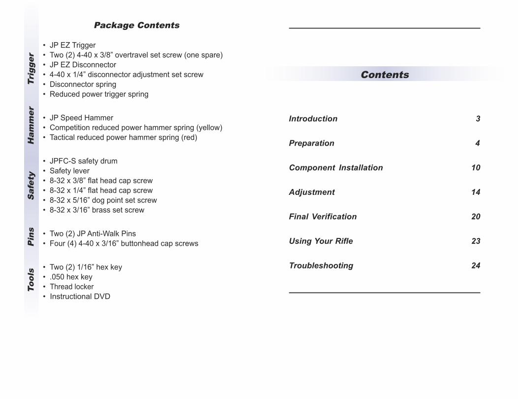
Contents
Introduction 3
Preparation 4
Component Installation 10
Adjustment 14
Final Verification 20
Using Your Rifle 23
Troubleshooting 24
Package Contents
• JP EZ Trigger
• Two (2) 4-40 x 3/8” overtravel set screw (one spare)
• JP EZ Disconnector
• 4-40 x 1/4” disconnector adjustment set screw
• Disconnector spring
• Reduced power trigger spring
• JP Speed Hammer
• Competition reduced power hammer spring (yellow)
• Tactical reduced power hammer spring (red)
• JPFC-S safety drum
• Safety lever
• 8-32 x 3/8” flat head cap screw
• 8-32 x 1/4” flat head cap screw
• 8-32 x 5/16” dog point set screw
• 8-32 x 3/16” brass set screw
• Two (2) JP Anti-Walk Pins
• Four (4) 4-40 x 3/16” buttonhead cap screws
• Two (2) 1/16” hex key
• .050 hex key
• Thread locker
• Instructional DVD
Tool
s
P
ins
S
afet
y
Ham
mer
Tri
gger
- 2 - - 3 -
Introduction
Thank you for purchasing the JP EZ Trigger™ for your gas
gun application. The installation of this fire control system can
be performed by almost anyone, takes only about five
minutes, and avoids any troublesome gunsmith fitting and the
danger of ruining parts. The design intent was to make it
possible for even those with limited tools or mechanical
knowledge to achieve a successful, expert trigger installation.
The JP EZ Trigger™ combines the versatility of our proven
component parts with the convenience of a modular trigger. It
really is the best of all worlds—a superb trigger job on par with
our own professional in-house installation, the speed and
ease of a module and the versatility of a components trigger.
Before beginning the installation, read these instructions
thoroughly and review the instructional DVD video included in
the packaging (and also available on our website at
www.jprifles.com/4.1.php). This video details our professional
in-house installation procedure as a visual aid for the process.
JP high performance firearm components represent the state of the art
in their respective product categories. However, be aware that any
change to the original design of the firearm may yield performance
improvement in one area but usually at the expense of something else.
It is your responsibility to determine if any aftermarket component is
suited to your application. When in doubt, call our technical support line
for guidance: 651-426-9196
All JP Fire Control components are designed and intended for semi-
automatic use only and will not function in a full-auto application.
Attempting to use these components in a full-auto application will place
you in violation of federal law.
NOTICE
No liability is expressed or implied for damage, injury or death resulting
from the improper installation or use/misuse of this product.
Like skydiving or rock climbing, the handling and use of firearms carries
with it certain unavoidable risks. In you are not willing to accept the
responsibility for your own actions, firearm ownership is not for you.
The use of any custom parts or modifications may void the warranty
from the manufacturer of your firearm.
We strongly recommend that a qualified gunsmith check the safety and
function of your modified firearm.
Before performing any work or modification on your firearm, make sure it
is clear. Remove any magazines, open the action and visually check the
chamber to ensure that your firearm is completely unloaded.
- 5 -- 4 -
this, make sure to practice the adjustment steps at least once
before committing to the thread locker. If it sets before you
obtain the correct setting, you will have to apply heat to the set
screw collar to degrade the thread locker and remove the set
screw, then clean the screw and collar for another run. Make
sure also not to apply excess thread locker. If the thread locker
bleeds into the pin bearings or between the trigger and the
receiver, it will lock up the entire mechanism.
Spring Selection
The final pull weight of the JP EZ Trigger™ is determined
primarily by the spring setup and will range from three to five
pounds depending on the choice of hammer spring. For
recreational or competition applications where absolute
reliability is not a necessity, we recommend using the yellow
competition hammer spring, which will yield a final pull of 3-3.5
pounds. Be aware that this spring setup may not yield full
ignition reliability with military primers.
Alternately, the red tactical spring will yield a pull of 3.5-4
pounds and full ignition with all primers. The red tactical
hammer spring must be used if you are installing the JP EZTrigger™ in a .308 rifle, which requires a heavier pull weight
in order to prevent the “finger bounce” doubling effect. Any
rifle that will be used for military/police duty or home defense
must also use this spring to ensure full ignition reliability.
To perform the installation, you will need to provide the
following items:
• padded vice
• plastic mallet
• drift pin / slave pin
• 5/64 hex key
• quality gun grease (such as Rydol®)
• lacquer thinner or acetone
• compressed air
• protective eyewear
Using Thread Locker
The JP EZ Trigger™ and adjustable disconnector include
adjustment set screws in order to optimize function for the
particular receiver. If these adjustments are set properly the
first time, they should not have to be readjusted or tuned. To
complete the final setup, thread locker must be used and will
never loosen once cured unless heat is applied to the screw
collars. Do not use Loctite® 242 (blue) or substitute products
like nail polish.
When using the included thread locker, be aware that you will
have somewhere between a few minutes to an hour of
working time, depending on humidity and heat. Because of
- 7 -- 6 -
Preparation
Terms of orientation in these instructions—such as the right/left
side of the rifle—assume the perspective of the operator
handling the rifle as normal with the muzzle facing away.
1. Remove the magazine from the rifle and verify that thechamber is clear before proceeding
2. Separate the upper and lower receiver assembliesFirst, push out the rear takedown pin until it comes to a
positive stop. Pivot the upper assembly down and away
from the lower assembly. Then, press out the front pivot
pin in the same way as the rear takedown pin. Separate
the assemblies and lay the upper assembly aside.
3. Secure the lower assembly in a padded viceThere are several options for clampable vice blocks that
insert into the magazine well, but you can also clamp the
receiver itself between wooden blocks around the outside
of the magazine well. In either case, be sure you have
access to the top opening in the receiver, the trigger and
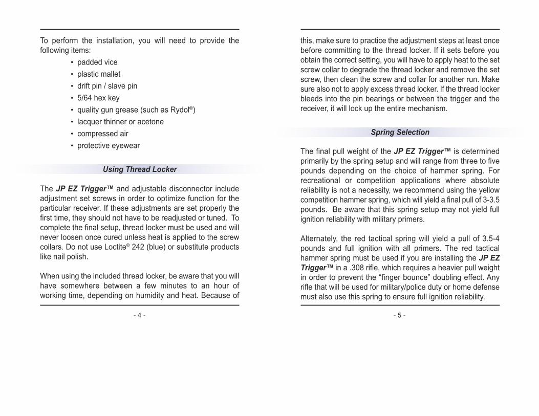
If you wish to achieve a 4.5-lb. trigger for service rifle high-
power competition, use your original trigger return spring and
hammer spring rather than those supplied. Be aware that it
may be necessary to increase the tension on the trigger return
spring to achieve the 4.5-lb. weight due to the minimal
hammer camming effect from our improved sear geometry.
You can do this by bending the two legs of the spring further
down about 20° to 25° (as shown) to apply more return
tension. By “tuning” the trigger return spring and slightly
increasing engagement, you should be
able to accurately tune the finished
trigger weight to meet your
requirement. If you would like an extra
set of springs pre-balanced for the 4.5-
lb. weight, you can order one from JP.
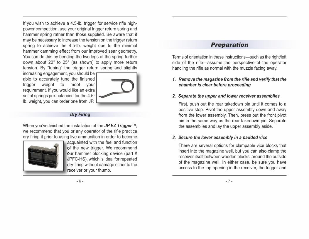
Dry Firing
When you’ve finished the installation of the JP EZ Trigger™,
we recommend that you or any operator of the rifle practice
dry-firing it prior to using live ammunition in order to become
acquainted with the feel and function
of the new trigger. We recommend
our hammer blocking device (part #
JPFC-HS), which is ideal for repeated
dry-firing without damage either to the
receiver or your thumb.
6. Remove the existing fire control componentsUsing the plastic mallet and drift pin, carefully tap the
existing trigger pins out of the lower receiver. First remove
the hammer pin and hammer followed by the trigger pin,
trigger and disconnector.
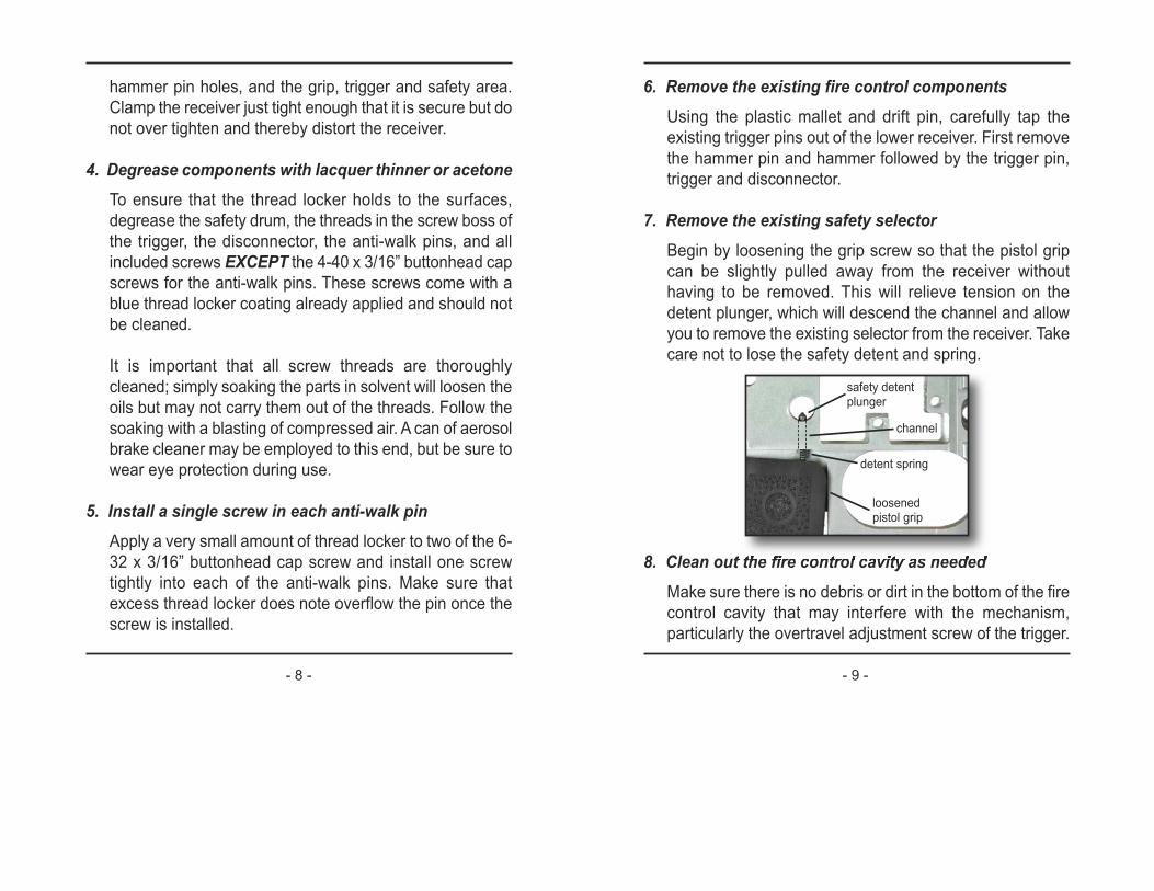
7. Remove the existing safety selectorBegin by loosening the grip screw so that the pistol grip
can be slightly pulled away from the receiver without
having to be removed. This will relieve tension on the
detent plunger, which will descend the channel and allow
you to remove the existing selector from the receiver. Take
care not to lose the safety detent and spring.
8. Clean out the fire control cavity as neededMake sure there is no debris or dirt in the bottom of the fire
control cavity that may interfere with the mechanism,
particularly the overtravel adjustment screw of the trigger.
- 8 - - 9 -
safety detentplunger
detent spring
channel
loosenedpistol grip
hammer pin holes, and the grip, trigger and safety area.
Clamp the receiver just tight enough that it is secure but do
not over tighten and thereby distort the receiver.
4. Degrease components with lacquer thinner or acetoneTo ensure that the thread locker holds to the surfaces,
degrease the safety drum, the threads in the screw boss of
the trigger, the disconnector, the anti-walk pins, and all
included screws EXCEPT the 4-40 x 3/16” buttonhead cap
screws for the anti-walk pins. These screws come with a
blue thread locker coating already applied and should not
be cleaned.
It is important that all screw threads are thoroughly
cleaned; simply soaking the parts in solvent will loosen the
oils but may not carry them out of the threads. Follow the
soaking with a blasting of compressed air. A can of aerosol
brake cleaner may be employed to this end, but be sure to
wear eye protection during use.
5. Install a single screw in each anti-walk pinApply a very small amount of thread locker to two of the 6-
32 x 3/16” buttonhead cap screw and install one screw
tightly into each of the anti-walk pins. Make sure that
excess thread locker does note overflow the pin once the
screw is installed.
- 10 - - 11 -
Component Installation
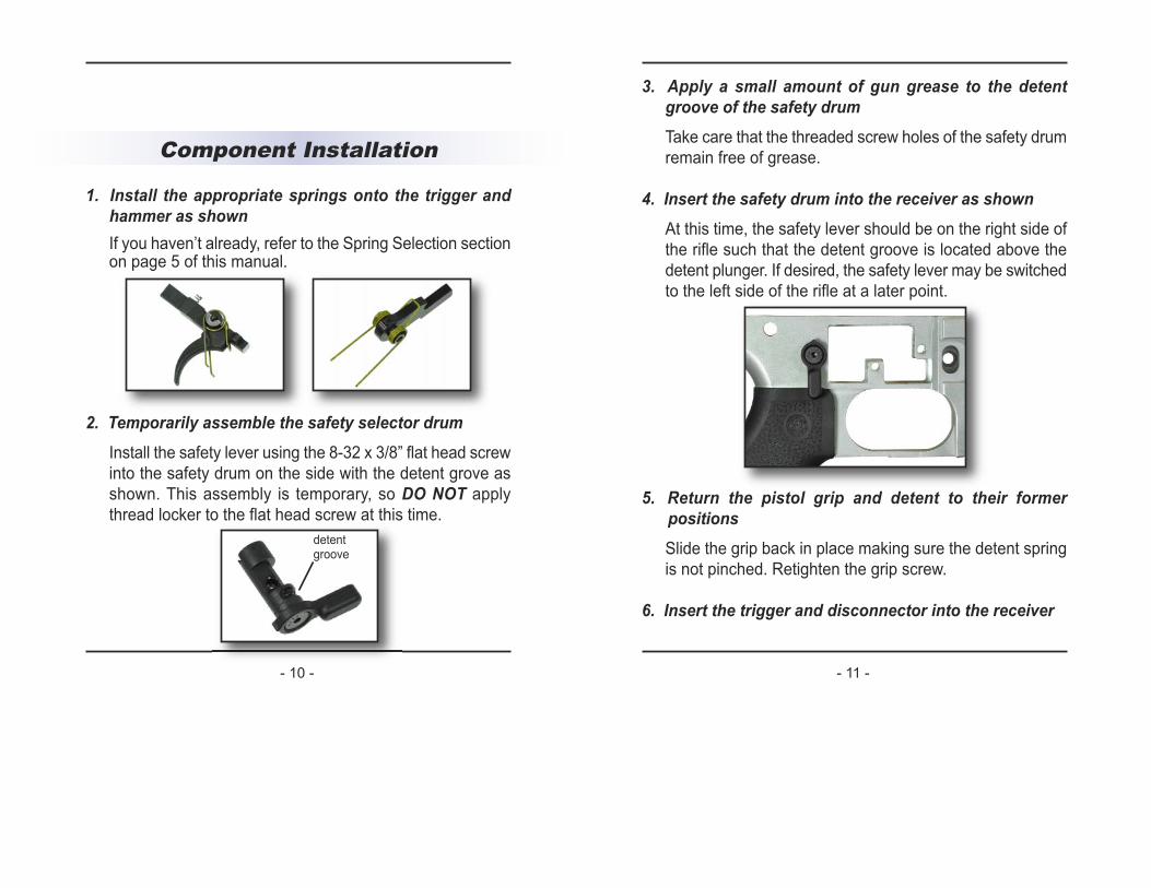
1. Install the appropriate springs onto the trigger andhammer as shownIf you haven’t already, refer to the Spring Selection sectionon page 5 of this manual.
2. Temporarily assemble the safety selector drumInstall the safety lever using the 8-32 x 3/8” flat head screw
into the safety drum on the side with the detent grove as
shown. This assembly is temporary, so DO NOT apply
thread locker to the flat head screw at this time.
detentgroove
3. Apply a small amount of gun grease to the detentgroove of the safety drumTake care that the threaded screw holes of the safety drum
remain free of grease.
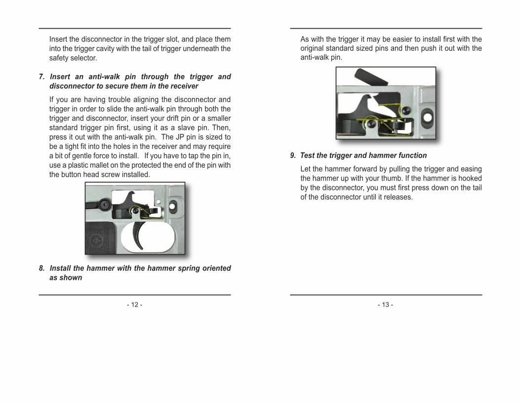
4. Insert the safety drum into the receiver as shownAt this time, the safety lever should be on the right side of
the rifle such that the detent groove is located above the
detent plunger. If desired, the safety lever may be switched
to the left side of the rifle at a later point.
5. Return the pistol grip and detent to their formerpositionsSlide the grip back in place making sure the detent spring
is not pinched. Retighten the grip screw.
6. Insert the trigger and disconnector into the receiver
As with the trigger it may be easier to install first with theoriginal standard sized pins and then push it out with theanti-walk pin.
9. Test the trigger and hammer functionLet the hammer forward by pulling the trigger and easing
the hammer up with your thumb. If the hammer is hooked
by the disconnector, you must first press down on the tail
of the disconnector until it releases.
Insert the disconnector in the trigger slot, and place them
into the trigger cavity with the tail of trigger underneath the
safety selector.
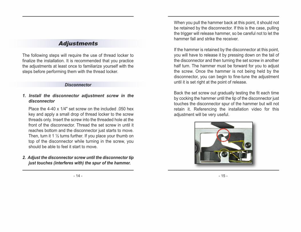
7. Insert an anti-walk pin through the trigger anddisconnector to secure them in the receiverIf you are having trouble aligning the disconnector and
trigger in order to slide the anti-walk pin through both the
trigger and disconnector, insert your drift pin or a smaller
standard trigger pin first, using it as a slave pin. Then,
press it out with the anti-walk pin. The JP pin is sized to
be a tight fit into the holes in the receiver and may require
a bit of gentle force to install. If you have to tap the pin in,
use a plastic mallet on the protected the end of the pin with
the button head screw installed.
8. Install the hammer with the hammer spring orientedas shown
- 12 - - 13 -
When you pull the hammer back at this point, it should not
be retained by the disconnector. If this is the case, pulling
the trigger will release hammer, so be careful not to let the
hammer fall and strike the receiver.
If the hammer is retained by the disconnector at this point,
you will have to release it by pressing down on the tail of
the disconnector and then turning the set screw in another
half turn. The hammer must be forward for you to adjust
the screw. Once the hammer is not being held by the
disconnector, you can begin to fine-tune the adjustment
until it is set right at the point of release.
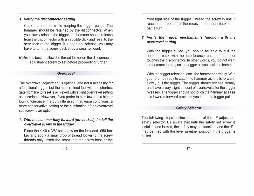
Back the set screw out gradually testing the fit each time
by cocking the hammer until the tip of the disconnector just
touches the disconnector spur of the hammer but will not
retain it. Referencing the installation video for this
adjustment will be very useful.
Adjustments
The following steps will require the use of thread locker to
finalize the installation. It is recommended that you practice
the adjustments at least once to familiarize yourself with the
steps before performing them with the thread locker.
Disconnector
1. Install the disconnector adjustment screw in thedisconnectorPlace the 4-40 x 1/4" set screw on the included .050 hex
key and apply a small drop of thread locker to the screw
threads only. Insert the screw into the threaded hole at the
front of the disconnector. Thread the set screw in until it
reaches bottom and the disconnector just starts to move.
Then, turn it 1 ½ turns further. If you place your thumb on
top of the disconnector while turning in the screw, you
should be able to feel it start to move.
2. Adjust the disconnector screw until the disconnector tipjust touches (interferes with) the spur of the hammer.
- 14 - - 15 -
front right side of the trigger. Thread the screw in until it
reaches the bottom of the receiver, and then back it out
half a turn.
2. Verify the trigger mechanism’s function with theovertravel setting
With the trigger pulled, you should be able to pull the
hammer back with no interference until the hammer
touches the disconnector. In other words, you do not want
the hammer to drag on the trigger as you cock the hammer.
With the trigger released, cock the hammer normally. With
your thumb ready to catch the hammer as it falls forward,
slowly pull the trigger. The trigger should release cleanly
and have a very slight amount of overtravel after the trigger
releases. The trigger should not touch the hammer at all as
it is lowered forward provided you keep the trigger pulled.
Safety Selector
The following steps outline the setup of the JP adjustable
safety selector. Be aware that until the safety set screw is
installed and locked, the safety may not function, and the rifle
may be fired with the lever in either position if the trigger is
pulled.
3. Verify the disconnector settingCock the hammer while keeping the trigger pulled. The
hammer should be retained by the disconnector. When
you slowly release the trigger, the hammer should release
from the disconnector with an audible click and reset to the
sear face of the trigger. If it does not release, you may
have to turn the screw back in by a small amount.
Note: It is best to allow the thread locker on the disconnector
adjustment screw to set before proceeding further.
Overtravel
The overtravel adjustment is optional and not a necessity for
a functional trigger, but the most refined feel with the shortest
gate from fire to reset is achieved with a tight overtravel setting
as described. However, if you prefer to bias towards a higher
fouling tolerance in a duty rifle used in adverse conditions, a
more conservative setting or the elimination of the overtravel
set screw is an option.
1. With the hammer fully forward (un-cocked), install theovertravel screw in the triggerPlace the 4-40 x 3/8" set screw on the included .050 hex
key and apply a small drop of thread locker to the screw
threads only. Insert the screw into the screw boss at the
- 16 - - 17 -
Place the 8-32 x 3/16" brass set screw on your 5/64” hex
key and apply a small drop of thread locker to the screw
threads only. Insert the screw into the threaded hole on the
safety drum. Thread the screw in until it contacts the dog
point set screw and tension it hand-tight.
5. Remove the safety lever and install it as desiredOnce removed from the safety drum, the safety lever and
8-32 x 3/8” flat head screw can be installed into the drum
on the left side (for right-handed shooters) or right side (for
left-handed shooters) with a drop of thread locker on the
threads of the screw.
6. If you do not desire an ambidextrous safety, install theremaining flat head screw in the open side of thesafety drumApply thread locker to the threads of the 8-32 x 1/4” flat
head screw and insert it into the open side of the safety.
If you would prefer an ambidextrous safety, you will need
the extra safety lever available from JP (part # JPFC-SL1),
which can be installed as outlined in step 5 above. Be
aware that if you choose to install the second lever at a
later date, you will need to apply heat with a blow torch to
break the thread locker holding the 8-32 x 1/4” screw
installed in this step.
1. Cock the hammer and then turn the safety lever to theSAFE position
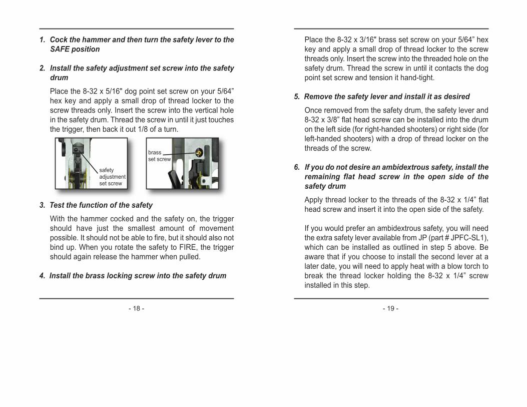
2. Install the safety adjustment set screw into the safetydrumPlace the 8-32 x 5/16" dog point set screw on your 5/64”
hex key and apply a small drop of thread locker to the
screw threads only. Insert the screw into the vertical hole
in the safety drum. Thread the screw in until it just touches
the trigger, then back it out 1/8 of a turn.
3. Test the function of the safetyWith the hammer cocked and the safety on, the trigger
should have just the smallest amount of movement
possible. It should not be able to fire, but it should also not
bind up. When you rotate the safety to FIRE, the trigger
should again release the hammer when pulled.
4. Install the brass locking screw into the safety drum
safety adjustmentset screw
brass set screw
- 18 - - 19 -
- 21 -- 20 -
3. Reassemble the upper and lower receivers
4. Verify function of the trigger mechanism as follows:
1. Turn the safety to FIRE position
2. Cycle the bolt with the charging handle
3. Squeeze the trigger but do not release it
4. Cycle the action again while still holding the trigger back
5. Release the trigger while listening for the click of the hammer reconnecting
6. Repeat this process several times
5. Verify the function of the safety as follows:
1. Turn the safety to the SAFE position
2. Pull the trigger to make sure the hammer does not fall
3. Release the trigger
4. Turn the safety to the FIRE position and verify that the hammer does not fall
5. Repeat this process several times
6. Allow the thread locker to set up for at least 24 hoursprior to firing the rifle
7. Test the tightness of the anti-walk pin screwsAfter the thread locker has set, use the two 1/16” hex keys
Finalization and Verification
If you encounter difficulties installing the JP EZ Trigger™ in
your receiver or cannot verify the success of the installation as
outlined below, call JP Technical Support at 651-426-9196. Do
not attempt to use your rifle with a potentially faulty trigger
mechanism.
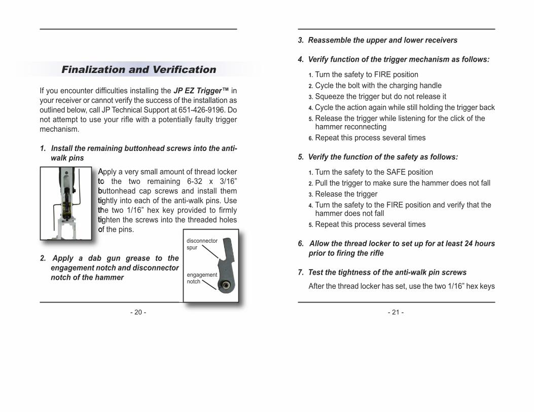
1. Install the remaining buttonhead screws into the anti-walk pins
Apply a very small amount of thread locker
to the two remaining 6-32 x 3/16”
buttonhead cap screws and install them
tightly into each of the anti-walk pins. Use
the two 1/16” hex key provided to firmly
tighten the screws into the threaded holes
of the pins.
2. Apply a dab gun grease to theengagement notch and disconnectornotch of the hammer engagement
notch
disconnectorspur
Using Your Rifle
Before firing or allowing anyone else to fire your rifle, the user
should dry-fire it first to get accustomed to the refined trigger.
(See page 6) While using your firearm, always remember the
following rules:
1. Handle all guns as if they were always loaded. 2. Never sweep yourself or anyone else with the muzzle. 3. Keep your finger out of the trigger guard until ready to fire.4. Be certain of your backstop and your target.
As a firearm operator, you must take responsibility for your
own actions. JP Enterprises will not be responsible for any
injury, death or property damage resulting from the use or
misuse of these parts.
Also, during operation of the rifle, take care never to engage
the safety selector if the hammer is in the FIRE position. This
may cause damage to the hammer/sear interface and
possibly crack the trigger. A properly fitted trigger/safety
selector relationship will not allow the selector to be engaged
(with hammer down) without forcing it.
to verify the tightness of the anti-walk pin screws. With one
wench in each of the screws on either side of the receiver,
apply light counterclockwise force to the screws of each
pin, which should not move. If the thread locker breaks
under light force, remove the screws, degrease the
components, and reinstall with thread locker.
- 22 - - 23 -
What is actually happening is a “fire on release”
situation. Specifically, the weapon fires when the
trigger is pulled and fires again when the trigger is
released because the hammer is released by the
disconnector before the sear is there to receive it.
If the rifle has worked properly for some period of
time and suddenly develops this problem, your
disconnector has probably worn back at the tip and
should be replaced. All M15-type rifles will develop
this problem given enough use. Still, a properly
timed disconnector will last many thousands of
cycles before failure.
The second common cause of doubling is the
“finger bounce” effect. There are even devices on
the market specifically designed to enhance this
effect resulting in mock full-auto fire. This problem
can be caused by a combination of improper trigger
control technique and a trigger release weight that
is too light. As the rifle moves in and out from your
shoulder under the recoil impulse, the trigger is
bouncing against your finger. If the trigger weight is
too light, your finger will trip the sear under the
recoil impulse resulting in multiple shots. This
technique is not appropriate with self-loading rifles.
For a demonstration of proper trigger control
technique as it relates to semi-automatic rifles,
Troubleshooting
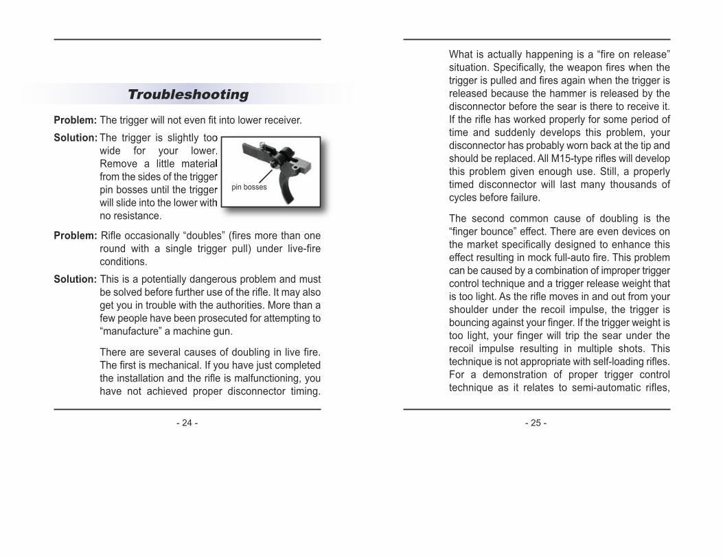
Problem: The trigger will not even fit into lower receiver.
Solution: The trigger is slightly too
wide for your lower.
Remove a little material
from the sides of the trigger
pin bosses until the trigger
will slide into the lower with
no resistance.
Problem: Rifle occasionally “doubles” (fires more than one
round with a single trigger pull) under live-fire
conditions.
Solution: This is a potentially dangerous problem and must
be solved before further use of the rifle. It may also
get you in trouble with the authorities. More than a
few people have been prosecuted for attempting to
“manufacture” a machine gun.
There are several causes of doubling in live fire.
The first is mechanical. If you have just completed
the installation and the rifle is malfunctioning, you
have not achieved proper disconnector timing.
pin bosses
- 24 - - 25 -
trigger reset tension. If you approach 3.5 lbs. and
still experience the problem, you may have some
other problem that needs professional attention,
which we can help to diagnose.
The final cause of firing more than one round per
pull of the trigger is the “slam-fire” effect. This is
caused by the firing pin striking the primer as the
bolt carrier assembly comes forward into battery at
high velocity. The inertia is imparted to the firing pin,
and as the bolt closes, the firing pin continues
forward at speed to strike the primer. You will notice
that, when unloaded, the last round in the chamber
will always show a firing pin witness mark due to
this effect. If the primer is sufficiently sensitive and
the firing pin velocity high enough, you may have a
slam fire. Always use appropriate primers (small
rifle or small rifle magnum) for a semi-auto rifle. Use
of certain operating system components that speed
up the bolt velocity or over-gassed operating
system can exacerbate this problem. If the double
occurs so fast that it is almost indistinguishable,
then it is probably a slam fire. The sure fix for a
constantly slam firing rifle is to switch to a titanium
firing pin. The lower mass of the titanium firing pin
makes it impossible for the pin to transfer enough
kinetic energy to cause ignition.
watch the DVD GasGunBasics™ produced by JP
Enterprise, Inc. It has a wealth of information
regarding all aspects of use, maintenance, loading,
optics selection and proper bench technique
including trigger control.
The doubling effect is also most common when the
finished weight of the trigger is below 3 lbs. Weigh
the trigger with a weight or spring gauge to verify
that your finished trigger weight is at least 3.0 to 3.5
lbs. If it is much below 3 lbs., you should increase
the pull weight. This can be done without redoing
the set screws by increasing the hammer and/or
trigger spring tension, assuming that you have
proper engagement setting in the first place.
People who are accustomed to shooting bolt guns
with very light triggers and use “bench rest”
techniques are particularly prone to experiencing
this condition, as they have a very light grasp of the
rifle and feather the trigger. This is not an
appropriate technique for a self-loader. Additionally,
rifles not equipped with a muzzle brake—short-
barreled carbines in particular—require a heavier
trigger setup to avoid the finger bounce problem.
Remove the JP trigger spring and replace it with
the original. This will add about six ounces to the
pull weight. If that is insufficient, bend the legs
down about 25° (see page 6) to further increase the
- 26 - - 27 -
- 28 -
NotesProblem: Repeated ignition failures are occurring.
Solution: Our custom springs (color-coded yellow) are
balanced to give a 3- to 3.5-lb. pull weight and give
reliable ignition using domestic (US-manufactured)
ammunition and primers for recreational or
competitive shooting use. If your rifle’s intended
use is for military, police or home defense, or if you
intend to use foreign-manufactured ammunition,
you must use a full power Mil-spec hammer spring.
This will solve any ignition problems and give “duty”
ignition reliability, which should be the criterion if
lives may depend on the function of the weapon. If
you are using reloaded ammo, you may also have
high primers. Box the ammo with the case head up
and examine the primers making sure that all
primers are below flush.