Embed Size (px)
Citation preview

Danfoss A/S is not liable or bound by warranty if theseinstructions are not adhered to during installation or service.
The English language is used for the original instructions.Other languages are a translation of the original instructions.(Directive 2006/42/EC)
© Copyright Danfoss A/S
Table of Contents
1 Important information/Safety instructions . . . . . . . . . . . . . . . . . . . . . . . . . . . . . . . . . . . . . . . . . . . . . . . 41.1 General safety precautions . . . . . . . . . . . . . . . . . . . . . . . . . . . . . . . . . . . . . . . . . . . . . . . . . . . . . . . 41.2 Electrical connection . . . . . . . . . . . . . . . . . . . . . . . . . . . . . . . . . . . . . . . . . . . . . . . . . . . . . . . . . . . 4
2 Components and hardware specifications . . . . . . . . . . . . . . . . . . . . . . . . . . . . . . . . . . . . . . . . . . . . . . . 52.1 Mounting the box . . . . . . . . . . . . . . . . . . . . . . . . . . . . . . . . . . . . . . . . . . . . . . . . . . . . . . . . . . . . . 52.2 Components . . . . . . . . . . . . . . . . . . . . . . . . . . . . . . . . . . . . . . . . . . . . . . . . . . . . . . . . . . . . . . . . 62.3 Connecting to accessory bus . . . . . . . . . . . . . . . . . . . . . . . . . . . . . . . . . . . . . . . . . . . . . . . . . . . . . . 72.4 Hardware specifications . . . . . . . . . . . . . . . . . . . . . . . . . . . . . . . . . . . . . . . . . . . . . . . . . . . . . . . . . 8
3 System solutions . . . . . . . . . . . . . . . . . . . . . . . . . . . . . . . . . . . . . . . . . . . . . . . . . . . . . . . . . . . . . . . . . 93.1 Connections . . . . . . . . . . . . . . . . . . . . . . . . . . . . . . . . . . . . . . . . . . . . . . . . . . . . . . . . . . . . . . . . 93.2 Distribution circuit 2-5 . . . . . . . . . . . . . . . . . . . . . . . . . . . . . . . . . . . . . . . . . . . . . . . . . . . . . . . . . . 103.3 TWC/WCS . . . . . . . . . . . . . . . . . . . . . . . . . . . . . . . . . . . . . . . . . . . . . . . . . . . . . . . . . . . . . . . . . . 133.4 Cooling/Cooling2 . . . . . . . . . . . . . . . . . . . . . . . . . . . . . . . . . . . . . . . . . . . . . . . . . . . . . . . . . . . . . 14
4 Configuring the module . . . . . . . . . . . . . . . . . . . . . . . . . . . . . . . . . . . . . . . . . . . . . . . . . . . . . . . . . . . . 154.1 Language selection . . . . . . . . . . . . . . . . . . . . . . . . . . . . . . . . . . . . . . . . . . . . . . . . . . . . . . . . . . . . 154.2 Software selection/Set unit ID . . . . . . . . . . . . . . . . . . . . . . . . . . . . . . . . . . . . . . . . . . . . . . . . . . . . . 16
5 Manual test . . . . . . . . . . . . . . . . . . . . . . . . . . . . . . . . . . . . . . . . . . . . . . . . . . . . . . . . . . . . . . . . . . . . 175.1 Manual test set up . . . . . . . . . . . . . . . . . . . . . . . . . . . . . . . . . . . . . . . . . . . . . . . . . . . . . . . . . . . . . 175.2 Table of functions . . . . . . . . . . . . . . . . . . . . . . . . . . . . . . . . . . . . . . . . . . . . . . . . . . . . . . . . . . . . . 18
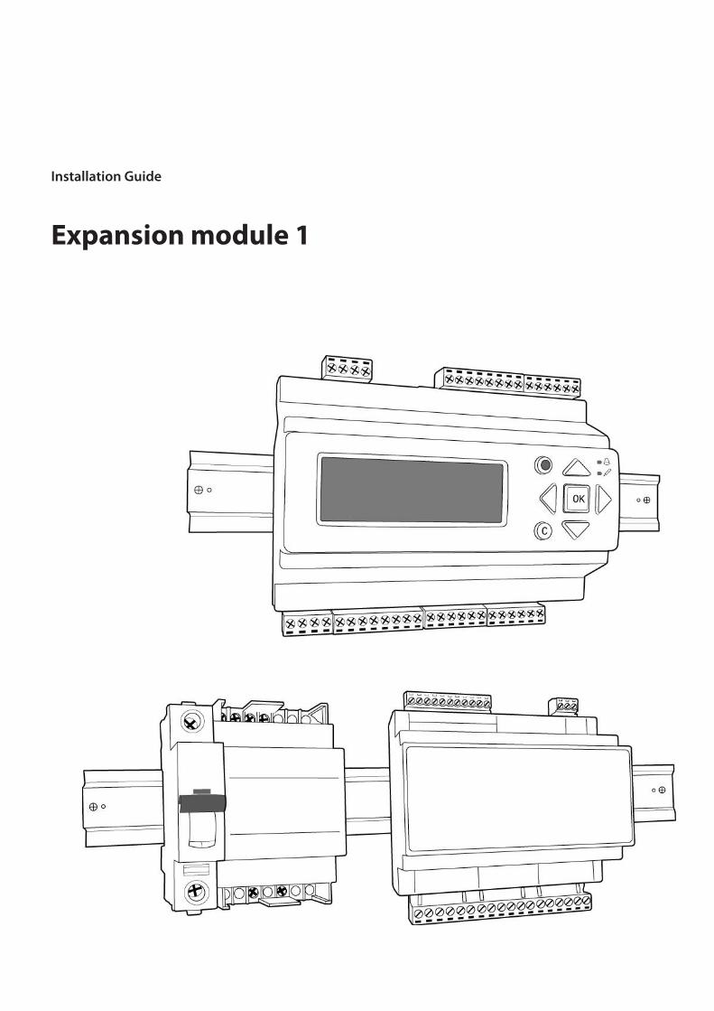
Installation Guide Expansion module 1
VQILV302 3
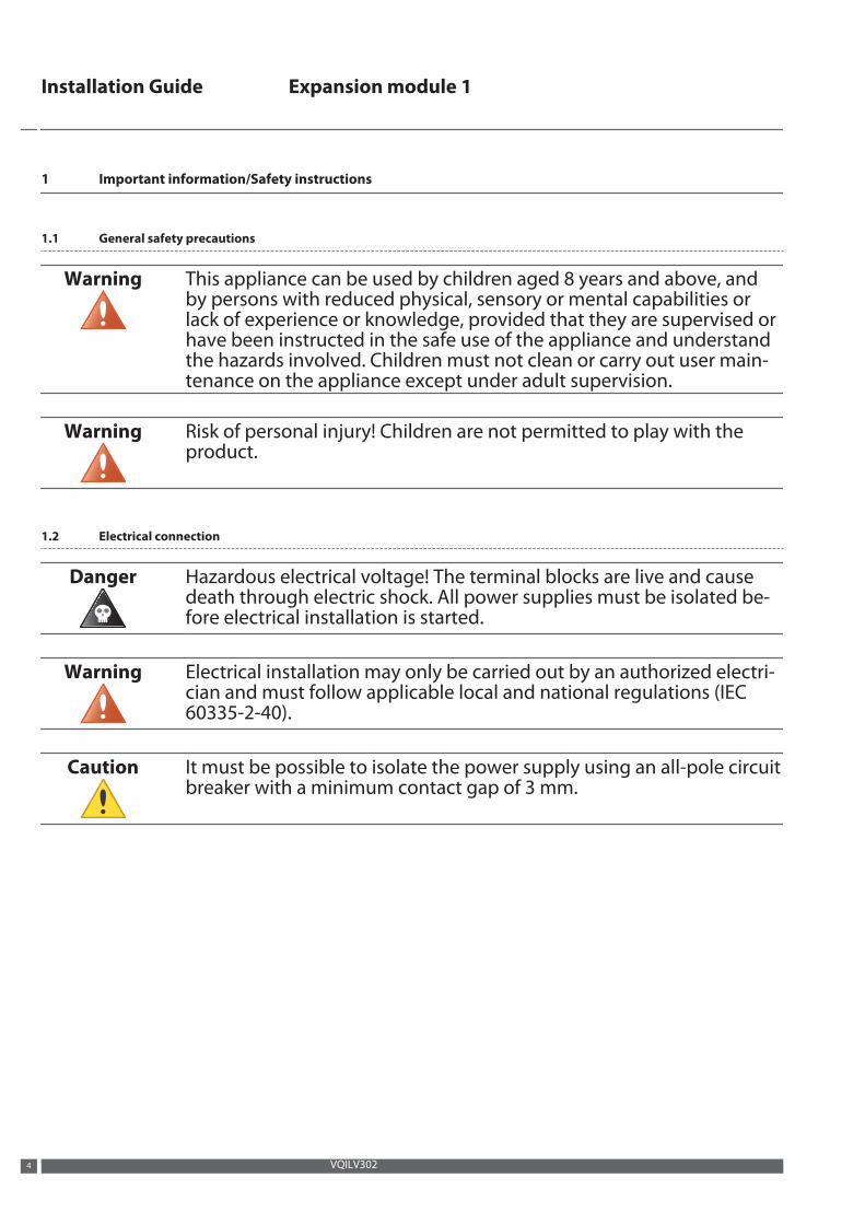
1 Important information/Safety instructions
1.1 General safety precautions
Warning This appliance can be used by children aged 8 years and above, andby persons with reduced physical, sensory or mental capabilities orlack of experience or knowledge, provided that they are supervised orhave been instructed in the safe use of the appliance and understandthe hazards involved. Children must not clean or carry out user main-tenance on the appliance except under adult supervision.
Warning Risk of personal injury! Children are not permitted to play with theproduct.
1.2 Electrical connection
Danger Hazardous electrical voltage! The terminal blocks are live and causedeath through electric shock. All power supplies must be isolated be-fore electrical installation is started.
Warning Electrical installation may only be carried out by an authorized electri-cian and must follow applicable local and national regulations (IEC60335-2-40).
Caution It must be possible to isolate the power supply using an all-pole circuitbreaker with a minimum contact gap of 3 mm.
Installation Guide Expansion module 1
VQILV3024
2 Components and hardware specifications
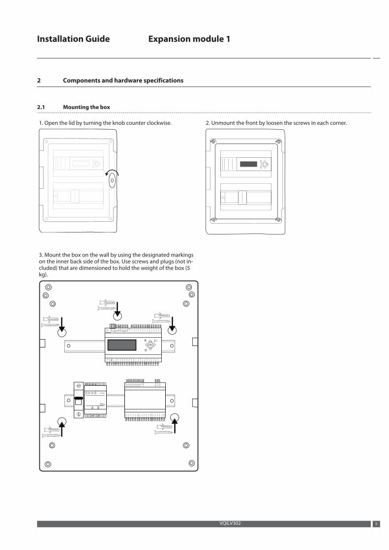
2.1 Mounting the box
1. Open the lid by turning the knob counter clockwise. 2. Unmount the front by loosen the screws in each corner.
3. Mount the box on the wall by using the designated markingson the inner back side of the box. Use screws and plugs (not in-cluded) that are dimensioned to hold the weight of the box (5kg).
P1
RxT
x
P/B
P2
RxT
x
P 1 P 2
B 5
0
A 5
1
N 5
2
E 5
3
B 6
0
A 6
1
N 6
2
E 6
3
Dl1
71
Dl2
72
Dl3
73
Dl4
74
Dl5
75
Dl6
76
Dl7
77
Dl8
78
Ag
nd
90
AO
1 9
1
AO
2 9
2
AO
3 9
3
AO
4 9
4
AO
5 9
5
1 G
+
32 G
0
-
4 +
C
10
GD
O
11
DO
1
12
DO
2
13
DO
3
14
DO
4
15
DO
5
16
DO
6
17
DO
7
31
Al1
30
Ag
nd
32
Al2
34
Al3
35
Al4
33
Ag
nd
41
Ul1
40
Ag
nd
42
Ul2
44
Ul3
45
Ul4
43
Ag
nd
C
OK
Ext.
Disp.
15
NO
16
NC
17
DO
1
18
NO
19
NC
20
DO
2
21
NO
22
NC
23
DO
3
24
NO
25
NC
26
DO
4
27
NO
28
NC
29
DO
5
30
NO
31
NC
32
DO
6
DO
1
C1
/2
DO
2
DO
3
C3
/4
DO
4
DO
5
C5
/6
DO
6
12
24
V~
13
24
V~
14
1 2 3 4 5 6 7 8 9 10
11
0V
1 2 3 4
24V
0V
10 12
230V
IP20
24V/1,67A
Installation Guide Expansion module 1
VQILV302 5
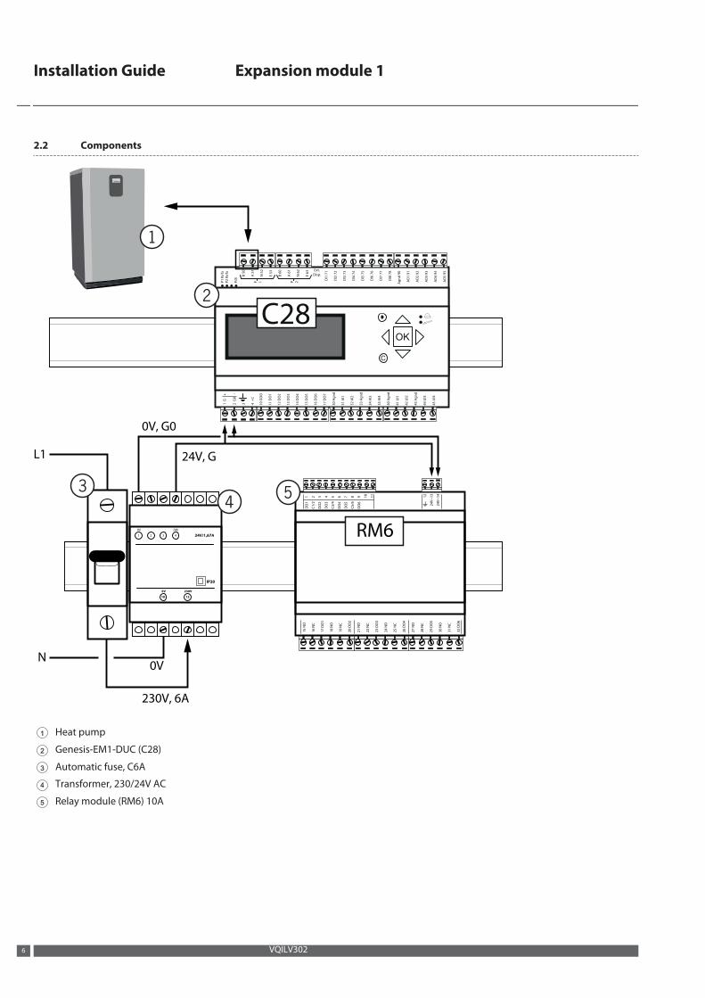
2.2 Components
P1
RxT
x
P/B
P2
RxT
x
P 1 P 2
B 5
0
A 5
1
N 5
2
E 5
3
B 6
0
A 6
1
N 6
2
E 6
3
Dl1
71
Dl2
72
Dl3
73
Dl4
74
Dl5
75
Dl6
76
Dl7
77
Dl8
78
Ag
nd
90
AO
1 9
1
AO
2 9
2
AO
3 9
3
AO
4 9
4
AO
5 9
5
1 G
+
32 G
0
-
4 +
C
10
GD
O
11
DO
1
12
DO
2
13
DO
3
14
DO
4
15
DO
5
16
DO
6
17
DO
7
31
Al1
30
Ag
nd
32
Al2
34
Al3
35
Al4
33
Ag
nd
41
Ul1
40
Ag
nd
42
Ul2
44
Ul3
45
Ul4
43
Ag
nd
C
OK
Ext.
Disp.
15
NO
16
NC
17
DO
1
18
NO
19
NC
20
DO
2
21
NO
22
NC
23
DO
3
24
NO
25
NC
26
DO
4
27
NO
28
NC
29
DO
5
30
NO
31
NC
32
DO
6
DO
1
C1
/2
DO
2
DO
3
C3
/4
DO
4
DO
5
C5
/6
DO
6
12
24
V~
13
24
V~
14
1 2 3 4 5 6 7 8 9 10
11
0V
1 2 3 4
24V
0V
10 12
230V
IP20
24V/1,67A
24V, G
0V, G0
230V, 6A
0V
L1
N
C28
RM6
1 Heat pump
2 Genesis-EM1-DUC (C28)
3 Automatic fuse, C6A
4 Transformer, 230/24V AC
5 Relay module (RM6) 10A
Installation Guide Expansion module 1
VQILV3026
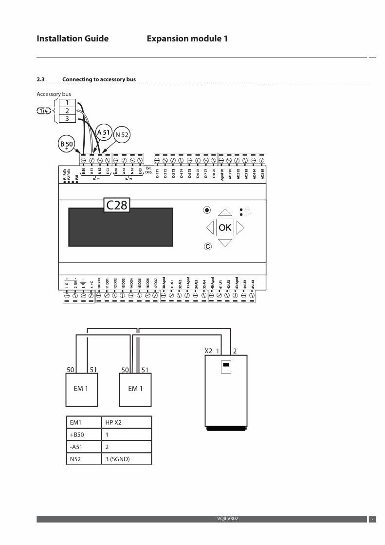
2.3 Connecting to accessory bus
Accessory bus
X2 21
50 51 50 51
EM 1 EM 1
EM1 HP X2
+B50 1
-A51 2
N52 3 (SGND)
B/P
B/P
B/P PPP
xxxTTTx
R 1
Px
R 1
Px
R 1
P 111 PPP 222
05
B0
5 B
05
B
xxxTTTx
R 2
Px
R 2
Px
R 2
P
1
5 A
1
5 A
1
5 A
25
N2
5 N
25
N
35
E3
5 E
35
E
06
B0
6 B
06
B
16
A1
6 A
16
A
26
N2
6 N
26
N
36
E3
6 E
36
E
17
1lD
17
1lD
17
1lD
27
2 lD
27
2 lD
27
2 lD
37
3 lD
37
3 lD
37
3 lD
47
4lD
47
4lD
47
4lD
57
5lD
57
5lD
57
5lD
67
6lD
67
6lD
67
6lD
77
7lD
77
7lD
77
7lD
87
8lD
87
8lD
87
8lD
19
1O
19
1O
19
1O
AAA
09
dn
09
dn
09
dn
gggAAA
29
2O
29
2O
29
2O
AAA
39
3O
39
3O
39
3O
AAA
49
4O
49
4O
49
4O
AAA
59
5O
59
5O
59
5O
AAA
+ G
1+
G 1
+ G
1 333
C+
4C
+ 4
C+
4
0
G 2
0
G 2
0
G 2
- - - OD
G 0
1O
DG
01
OD
G 0
1
1O
D 1
11
OD
11
1O
D 1
1
2O
D 2
12
OD
21
2O
D 2
1
3O
D 3
13
OD
31
3O
D 3
1
4O
D 4
14
OD
41
4O
D 4
1
5O
D 5
15
OD
51
5O
D 5
1
6O
D 6
16
OD
61
6O
D 6
1
7O
D 7
17
OD
71
7O
D 7
1
1lA
13
1lA
13
1lA
13
2lA
23
2lA
23
2lA
23
dn
dn
dn
gggA
03
A 0
3A
03
3lA
43
3lA
43
3lA
43
4lA
53
4lA
53
4lA
53
1lU
14
1lU
14
1lU
14
dn
dn
dn
gggA
33
A 3
3A
33
2 lU
24
2 lU
24
2 lU
24
dn
dn
dn
gggA
04
A 0
4A
04
3lU
44
3lU
44
3lU
44
4lU
54
4lU
54
4lU
54
dn
dn
dn
gggA
34
A 3
4A
34
CCC
KOKOKO
.t.t.txExExE
...psiD psiD psiD
15 A 15 A 15 A 25 N
05 B 05 B 05 B
C28
123
Installation Guide Expansion module 1
VQILV302 7
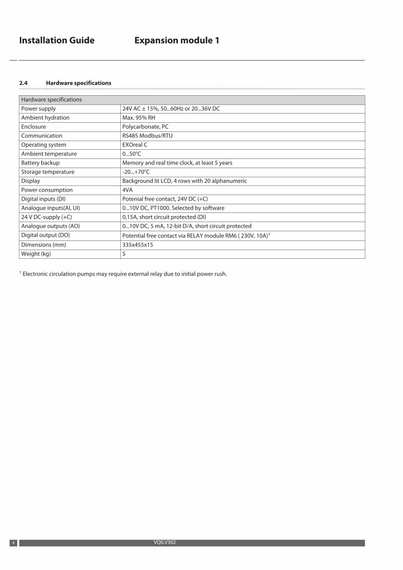
2.4 Hardware specifications
Hardware specificationsPower supply 24V AC ± 15%, 50...60Hz or 20...36V DCAmbient hydration Max. 95% RHEnclosure Polycarbonate, PCCommunication RS485 Modbus/RTUOperating system EXOreal CAmbient temperature 0...50°CBattery backup Memory and real time clock, at least 5 yearsStorage temperature -20...+70°CDisplay Background lit LCD, 4 rows with 20 alphanumericPower consumption 4VADigital inputs (DI) Potenial free contact, 24V DC (+C)Analogue inputs(AI, UI) 0...10V DC, PT1000. Selected by software24 V DC-supply (+C) 0,15A, short circuit protected (DI)Analogue outputs (AO) 0...10V DC, 5 mA, 12-bit D/A, short circuit protectedDigital output (DO) Potential free contact via RELAY module RM6 ( 230V, 10A)1
Dimensions (mm) 335x455x15Weight (kg) 5
1 Electronic circulation pumps may require external relay due to initial power rush.
Installation Guide Expansion module 1
VQILV3028
3 System solutions
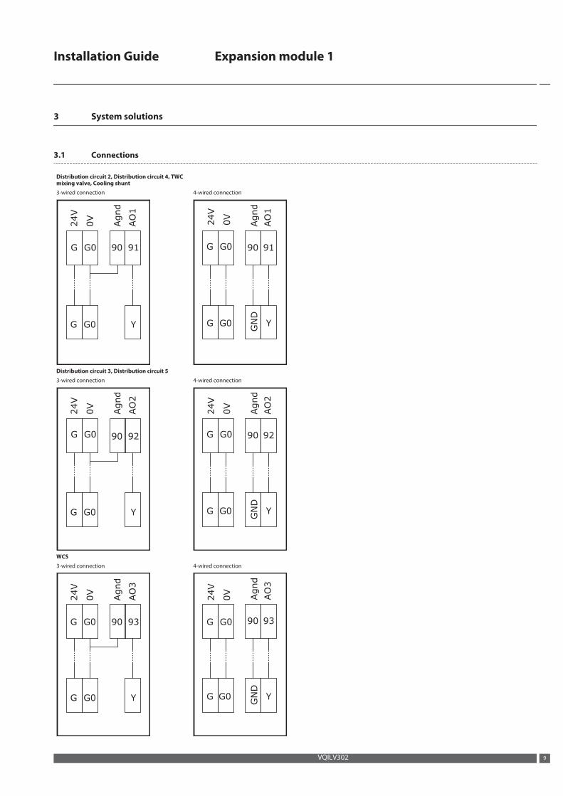
3.1 Connections
Distribution circuit 2, Distribution circuit 4, TWCmixing valve, Cooling shunt
3-wired connection 4-wired connection
9190
YG0G
AO1
Agnd
24V
0V
G0G 9190
Y
GND
G0G
AO1
Agnd
24V
0V
G0G
Distribution circuit 3, Distribution circuit 5
3-wired connection 4-wired connection
9290
YG0G
AO2
Agnd
G0G
24V
0V
9290
Y
GND
G0G
AO2
Agnd
G0G
24V
0V
WCS
3-wired connection 4-wired connection
9390
YG0G
G0G
24V
0V
AO3
Agnd
9390
Y
GND
G0G
G0G
24V
0V
AO3
Agnd
Installation Guide Expansion module 1
VQILV302 9
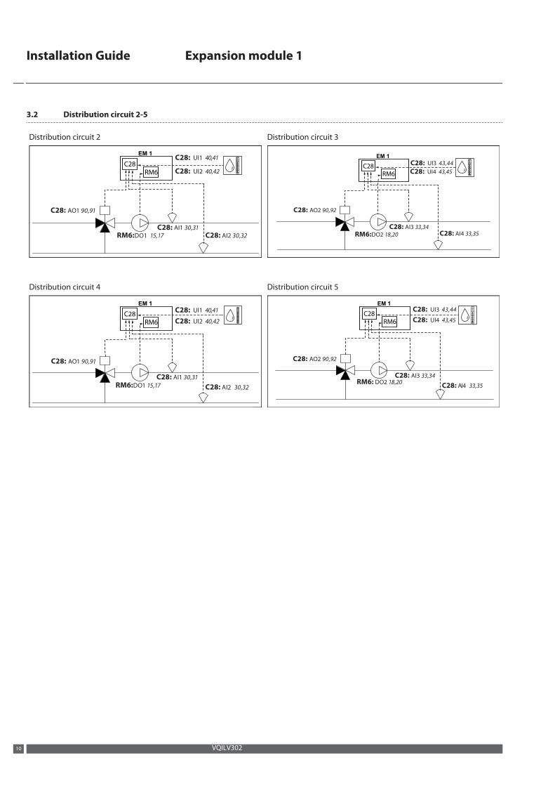
3.2 Distribution circuit 2-5
Distribution circuit 2 Distribution circuit 3
EM 1C28: UI1 40,41
C28: UI2 40,42
RM6: 1 DO 1715,
C28: AI1 30,31
C28: AI2 30,32
C28: AO1 90,91
EM 1
C28: UI3 43,44
C28: UI4 43,45
C28: AI3 33,34
RM6:DO2 18,20 C28: AI4 33,35
C28: AO2 90,92
Distribution circuit 4 Distribution circuit 5
EM 1
C28: UI1 40,41
C28: UI2 40,42
C28: AI1 30,31
RM6:DO1 15,17 C28: AI2 30,32
C28: AO1 90,91
EM 1
C28: UI3 43,44
C28: UI4 43,45
C28: AI3 33,34 RM6: DO2 18,20
C28: AI4 33,35
C28: AO2 90,92
Installation Guide Expansion module 1
VQILV30210
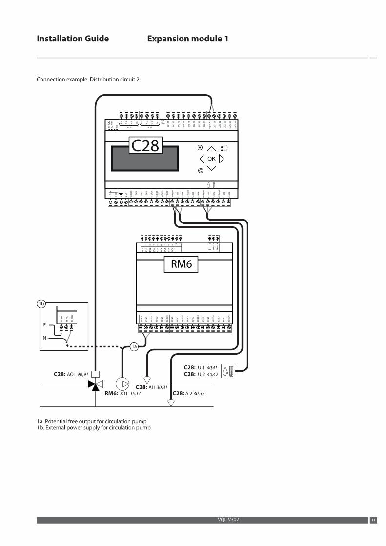
Connection example: Distribution circuit 2
C28: UI1 40,41
C28: UI2 40,42
RM6: 1 DO 1715,
C28: AI1 30,31
C28: AI2 30,32
C28: AO1
N
F
90,91
P1
RxT
x
P/B
P2
RxT
x
P 1 P 2
B 5
0
A 5
1
N 5
2
E 5
3
B 6
0
A 6
1
N 6
2
E 6
3
Dl1
71
Dl2
72
Dl3
73
Dl4
74
Dl5
75
Dl6
76
Dl7
77
Dl8
78
Ag
nd
90
AO
1 9
1
AO
2 9
2
AO
3 9
3
AO
4 9
4
AO
5 9
5
1 G
+
32 G
0
-
4 +
C
10
GD
O
11
DO
1
12
DO
2
13
DO
3
14
DO
4
15
DO
5
16
DO
6
17
DO
7
31
Al1
30
Ag
nd
32
Al2
34
Al3
35
Al4
33
Ag
nd
41
Ul1
40
Ag
nd
42
Ul2
44
Ul3
45
Ul4
43
Ag
nd
C
OK
Ext.
Disp.
15
NO
16
NC
17
DO
1
18
NO
19
NC
20
DO
2
21
NO
22
NC
23
DO
3
24
NO
25
NC
26
DO
4
27
NO
28
NC
29
DO
5
30
NO
31
NC
32
DO
6
DO
1
C1
/2
DO
2
DO
3
C3
/4
DO
4
DO
5
C5
/6
DO
6
12
24
V~
13
24
V~
14
1 2 3 4 5 6 7 8 9 10
11
C28
RM6
15
NO
16
NC
17
DO
1
1a
1b
1a. Potential free output for circulation pump1b. External power supply for circulation pump
Installation Guide Expansion module 1
VQILV302 11
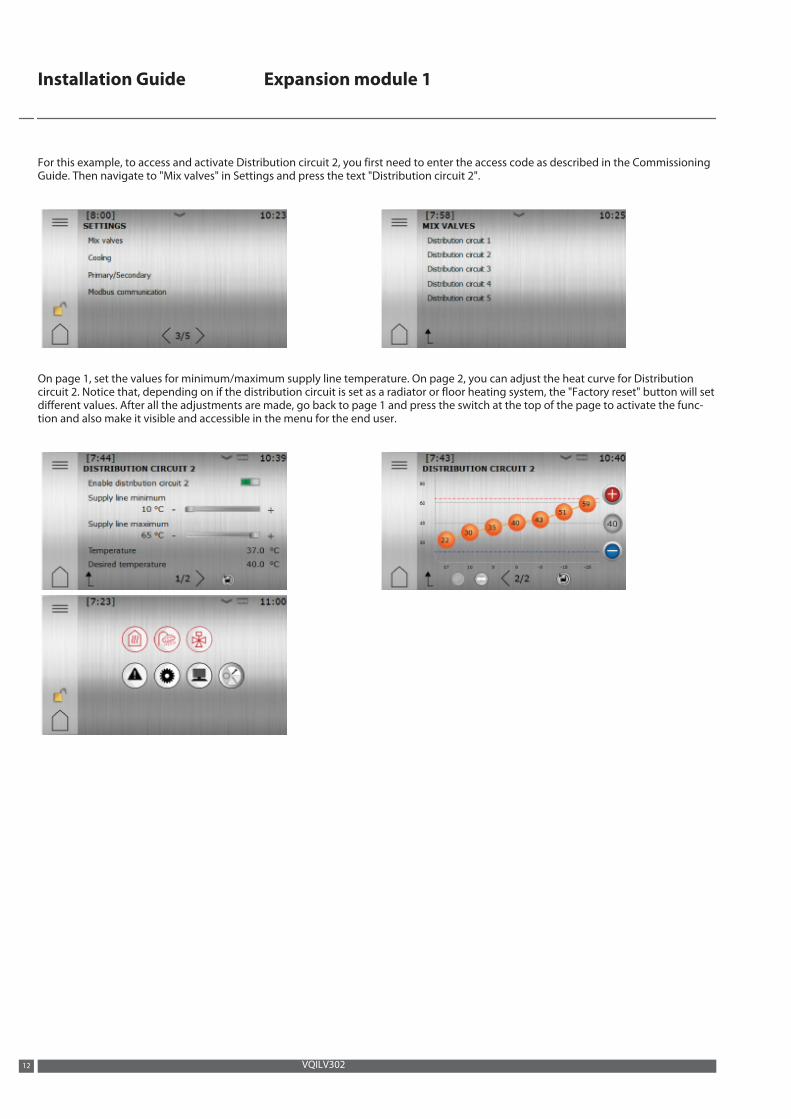
For this example, to access and activate Distribution circuit 2, you first need to enter the access code as described in the CommissioningGuide. Then navigate to "Mix valves" in Settings and press the text "Distribution circuit 2".
On page 1, set the values for minimum/maximum supply line temperature. On page 2, you can adjust the heat curve for Distributioncircuit 2. Notice that, depending on if the distribution circuit is set as a radiator or floor heating system, the "Factory reset" button will setdifferent values. After all the adjustments are made, go back to page 1 and press the switch at the top of the page to activate the func-tion and also make it visible and accessible in the menu for the end user.
Installation Guide Expansion module 1
VQILV30212
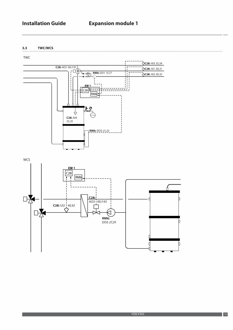
3.3 TWC/WCS
TWC
C28: AO1 90,Y:91
C28: AI3 33,34
C28: AI1 30,31
C28: AI4
33,35
C28: AI2 30,32RM6: DO1 15,17
RM6: DO3 21,23
EM 1
WCS
C28: UI2
C28:
AO3
40,42
RM6:
DO5 27,29
90,Y:93
EM 1
Installation Guide Expansion module 1
VQILV302 13
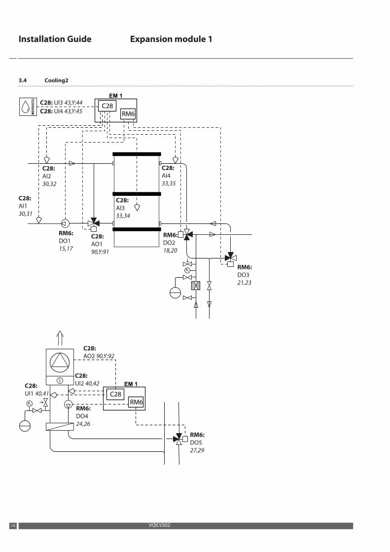
3.4 Cooling2
EM 1
C28: UI3 43,Y:44
C28: UI4 43,Y:45
C28:
AI2
30,32
C28:
AI1
30,31
RM6:
DO1
15,17
C28:
AO1
90,Y:91
C28:
AI3
33,34
C28:
AI4
33,35
RM6:
DO2
18,20
RM6:
DO3
21,23
EM 1
C28:
AO2 90,Y:92
RM6:
DO5
27,29
C28:
UI2 40,42C28:
UI1 40,41
RM6:
DO4
24,26
Installation Guide Expansion module 1
VQILV30214
4 Configuring the module
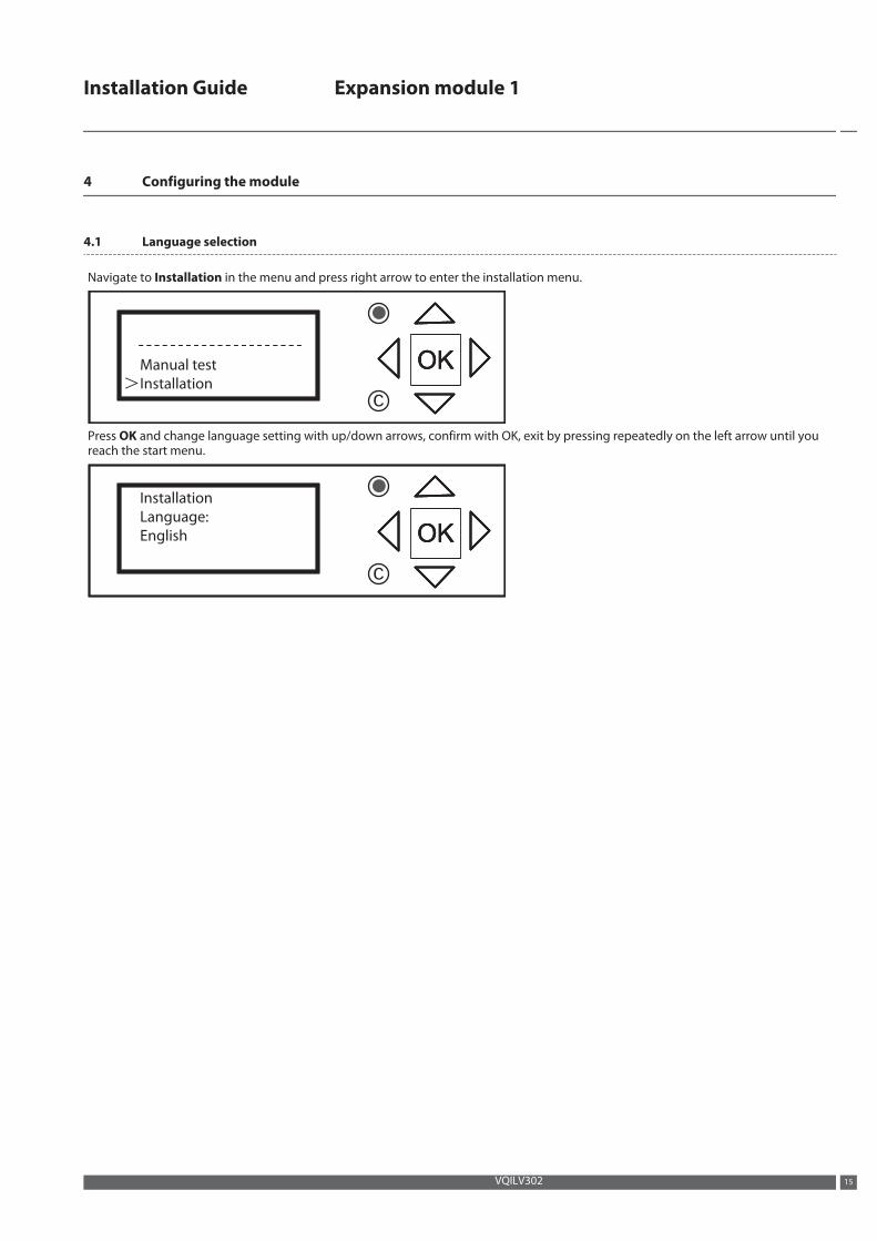
4.1 Language selection
Navigate to Installation in the menu and press right arrow to enter the installation menu.
Manual test
Installation
OKOK>
OK
c
Press OK and change language setting with up/down arrows, confirm with OK, exit by pressing repeatedly on the left arrow until youreach the start menu.
Installation
Language:
English OKOKOK
c
Installation Guide Expansion module 1
VQILV302 15
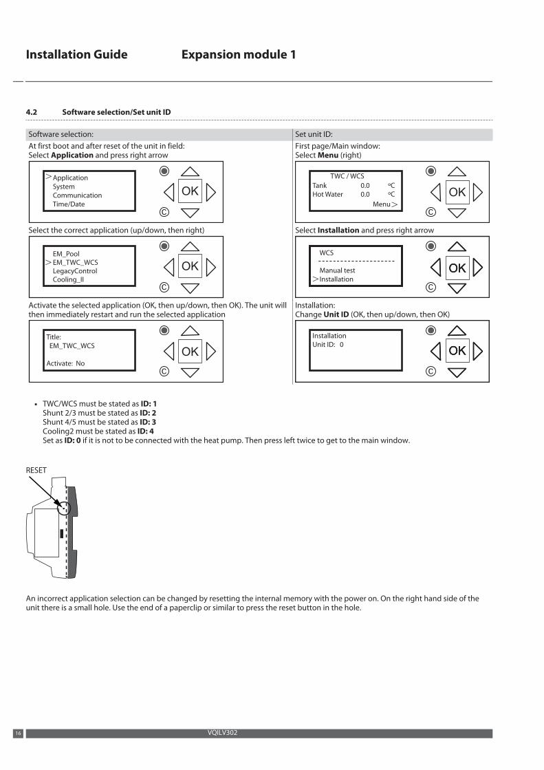
4.2 Software selection/Set unit ID
Software selection: Set unit ID:At first boot and after reset of the unit in field:Select Application and press right arrow
>Application
System
Communication
Time/Date
OK
c
First page/Main window:Select Menu (right)
Tank
Hot Water
TWC / WCS
0.0
0.0
ºC
ºC
Menu>
OK
c
Select the correct application (up/down, then right)
>EM_EM_T
PoolWC_WCS OK
c
LegacyControlCooling_II
Select Installation and press right arrow
WCS
Manual test
Installation
OKOK>
OK
c
Activate the selected application (OK, then up/down, then OK). The unit willthen immediately restart and run the selected application
Title:
EM_TWC_WCS
Activate: No
OK
c
Installation:Change Unit ID (OK, then up/down, then OK)
Installation
Unit ID: 0
OKOKOK
c
▪ TWC/WCS must be stated as ID: 1Shunt 2/3 must be stated as ID: 2Shunt 4/5 must be stated as ID: 3Cooling2 must be stated as ID: 4Set as ID: 0 if it is not to be connected with the heat pump. Then press left twice to get to the main window.
RESET
An incorrect application selection can be changed by resetting the internal memory with the power on. On the right hand side of theunit there is a small hole. Use the end of a paperclip or similar to press the reset button in the hole.
Installation Guide Expansion module 1
VQILV30216
5 Manual test
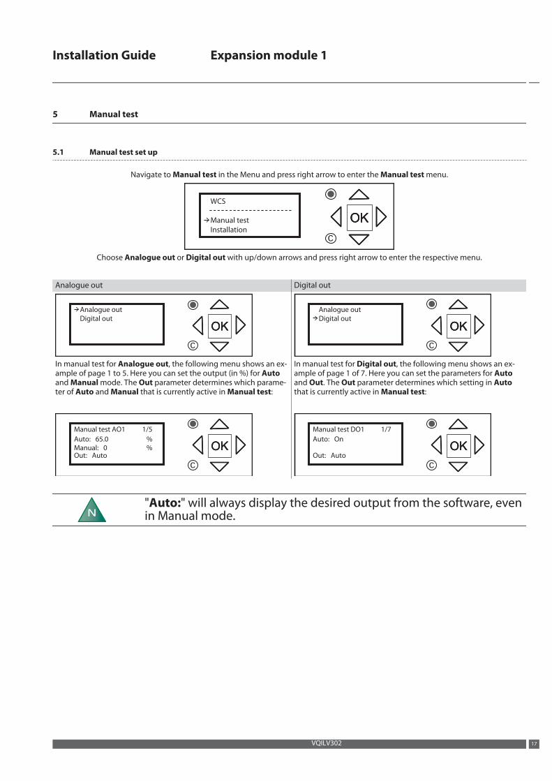
5.1 Manual test set up
Navigate to Manual test in the Menu and press right arrow to enter the Manual test menu.
WCS
Manual test
Installation
OKOKOK
c
Choose Analogue out or Digital out with up/down arrows and press right arrow to enter the respective menu.
Analogue out Digital out
Analogue out
Digital out
OKOKOK
c
Analogue out
Digital out
OKOKOK
c
In manual test for Analogue out, the following menu shows an ex-ample of page 1 to 5. Here you can set the output (in %) for Autoand Manual mode. The Out parameter determines which parame-ter of Auto and Manual that is currently active in Manual test:
Manual test AO1
Auto: 65.0
Manual: 0
Out: Auto
1/5
%
% OKOKOK
c
In manual test for Digital out, the following menu shows an ex-ample of page 1 of 7. Here you can set the parameters for Autoand Out. The Out parameter determines which setting in Autothat is currently active in Manual test:
Manual test DO1
Auto: On
Out: Auto
1/7
OKOKOK
c
N"Auto:" will always display the desired output from the software, evenin Manual mode.
Installation Guide Expansion module 1
VQILV302 17
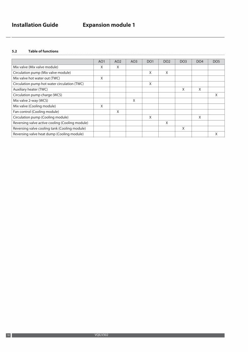
5.2 Table of functions
AO1 AO2 AO3 DO1 DO2 DO3 DO4 DO5Mix valve (Mix valve module) X XCirculation pump (Mix valve module) X XMix valve hot water out (TWC) XCirculation pump hot water circulation (TWC) XAuxiliary heater (TWC) X XCirculation pump charge (WCS) XMix valve 2-way (WCS) XMix valve (Cooling module) XFan control (Cooling module) XCirculation pump (Cooling module) X XReversing valve active cooling (Cooling module) XReversing valve cooling tank (Cooling module) XReversing valve heat dump (Cooling module) X
Installation Guide Expansion module 1
VQILV30218

Installation Guide Expansion module 1
VQILV302 19
Installation Guide Expansion module 1
VQILV302
Danfoss Heat PumpsBox 950SE 671 29 ARVIKAPhone +46 570 81300E-mail: [email protected]: www.heating.danfoss.com
Danfoss can accept no responsibility for possible errors in catalogues, brochures and other printed material. Danfoss reserves the right to alter its products without notice. This also applies to productsalready on order provided that such alterations can be made without subsequential changes being necessary in specifications already agreed. All trademarks in this material are property of the respectivecompanies. Danfoss Heating Solutions and the Danfoss Heating Solutions logotype are trademarks of Danfoss A/S. All rights reserved.
Produced by Danfoss Heating Solutions © 2016