Embed Size (px)
Citation preview
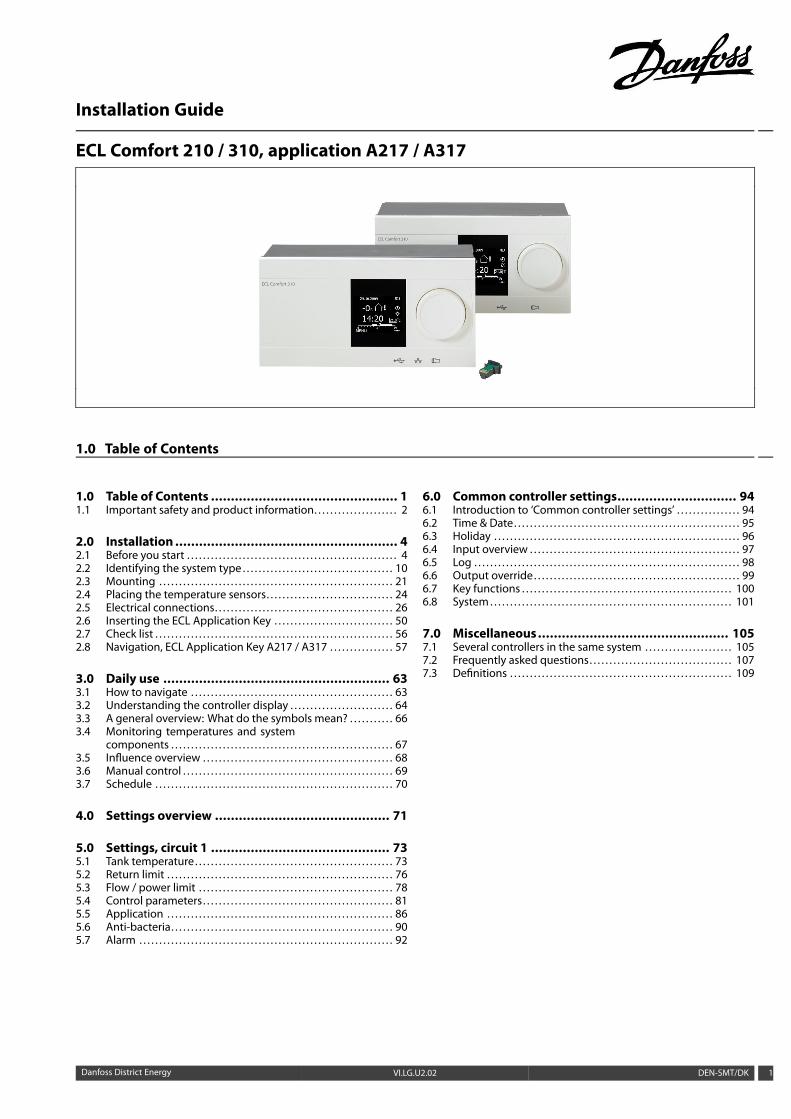
Installation Guide
ECL Comfort 210 / 310, application A217 / A317
1.0 Table of Contents
1.0 Table of Contents ............................................... 11.1 Important safety and product information. . . . . . . . . . . . . . . . . . . . . 2
2.0 Installation ........................................................ 42.1 Before you start . . . . . . . . . . . . . . . . . . . . . . . . . . . . . . . . . . . . . . . . . . . . . . . . . . . . . 42.2 Identifying the system type . . . . . . . . . . . . . . . . . . . . . . . . . . . . . . . . . . . . . . 102.3 Mounting . . . . . . . . . . . . . . . . . . . . . . . . . . . . . . . . . . . . . . . . . . . . . . . . . . . . . . . . . . . 212.4 Placing the temperature sensors. . . . . . . . . . . . . . . . . . . . . . . . . . . . . . . . 242.5 Electrical connections. . . . . . . . . . . . . . . . . . . . . . . . . . . . . . . . . . . . . . . . . . . . . 262.6 Inserting the ECL Application Key . . . . . . . . . . . . . . . . . . . . . . . . . . . . . . 502.7 Check list . . . . . . . . . . . . . . . . . . . . . . . . . . . . . . . . . . . . . . . . . . . . . . . . . . . . . . . . . . . . 562.8 Navigation, ECL Application Key A217 / A317 . . . . . . . . . . . . . . . . 57
3.0 Daily use ......................................................... 633.1 How to navigate . . . . . . . . . . . . . . . . . . . . . . . . . . . . . . . . . . . . . . . . . . . . . . . . . . . 633.2 Understanding the controller display . . . . . . . . . . . . . . . . . . . . . . . . . . 643.3 A general overview: What do the symbols mean? . . . . . . . . . . . 663.4 Monitoring temperatures and system
components . . . . . . . . . . . . . . . . . . . . . . . . . . . . . . . . . . . . . . . . . . . . . . . . . . . . . . . . 673.5 Influence overview . . . . . . . . . . . . . . . . . . . . . . . . . . . . . . . . . . . . . . . . . . . . . . . . 683.6 Manual control . . . . . . . . . . . . . . . . . . . . . . . . . . . . . . . . . . . . . . . . . . . . . . . . . . . . . 693.7 Schedule . . . . . . . . . . . . . . . . . . . . . . . . . . . . . . . . . . . . . . . . . . . . . . . . . . . . . . . . . . . . 70
4.0 Settings overview ............................................ 71
5.0 Settings, circuit 1 ............................................. 735.1 Tank temperature. . . . . . . . . . . . . . . . . . . . . . . . . . . . . . . . . . . . . . . . . . . . . . . . . . 735.2 Return limit . . . . . . . . . . . . . . . . . . . . . . . . . . . . . . . . . . . . . . . . . . . . . . . . . . . . . . . . . 765.3 Flow / power limit . . . . . . . . . . . . . . . . . . . . . . . . . . . . . . . . . . . . . . . . . . . . . . . . . 785.4 Control parameters. . . . . . . . . . . . . . . . . . . . . . . . . . . . . . . . . . . . . . . . . . . . . . . . 815.5 Application . . . . . . . . . . . . . . . . . . . . . . . . . . . . . . . . . . . . . . . . . . . . . . . . . . . . . . . . . 865.6 Anti-bacteria. . . . . . . . . . . . . . . . . . . . . . . . . . . . . . . . . . . . . . . . . . . . . . . . . . . . . . . . 905.7 Alarm . . . . . . . . . . . . . . . . . . . . . . . . . . . . . . . . . . . . . . . . . . . . . . . . . . . . . . . . . . . . . . . . 92
6.0 Common controller settings.............................. 946.1 Introduction to ‘Common controller settings’ . . . . . . . . . . . . . . . . 946.2 Time & Date. . . . . . . . . . . . . . . . . . . . . . . . . . . . . . . . . . . . . . . . . . . . . . . . . . . . . . . . . 956.3 Holiday . . . . . . . . . . . . . . . . . . . . . . . . . . . . . . . . . . . . . . . . . . . . . . . . . . . . . . . . . . . . . . 966.4 Input overview . . . . . . . . . . . . . . . . . . . . . . . . . . . . . . . . . . . . . . . . . . . . . . . . . . . . . 976.5 Log . . . . . . . . . . . . . . . . . . . . . . . . . . . . . . . . . . . . . . . . . . . . . . . . . . . . . . . . . . . . . . . . . . . 986.6 Output override. . . . . . . . . . . . . . . . . . . . . . . . . . . . . . . . . . . . . . . . . . . . . . . . . . . . 996.7 Key functions . . . . . . . . . . . . . . . . . . . . . . . . . . . . . . . . . . . . . . . . . . . . . . . . . . . . . 1006.8 System . . . . . . . . . . . . . . . . . . . . . . . . . . . . . . . . . . . . . . . . . . . . . . . . . . . . . . . . . . . . . 101
7.0 Miscellaneous................................................ 1057.1 Several controllers in the same system . . . . . . . . . . . . . . . . . . . . . . 1057.2 Frequently asked questions. . . . . . . . . . . . . . . . . . . . . . . . . . . . . . . . . . . . 1077.3 Definitions . . . . . . . . . . . . . . . . . . . . . . . . . . . . . . . . . . . . . . . . . . . . . . . . . . . . . . . . 109
Danfoss District Energy VI.LG.U2.02 DEN-SMT/DK 1
Installation Guide ECL Comfort 210 / 310, application A217 / A317
1.1 Important safety and product information
1.1.1 Important safety and product information
This Installation Guide is associated with ECL Application Key A217(order code no. 087H3807).
The A217 Key contains two sets of applications: one set (A217.1 /A217.2 / A217.3) and another set (A317.1 / A317.2).
The functions can be realized in:ECL Comfort 210 (A217) for simple solutions orECL Comfort 310 (A217 / A317) for advanced solutions, e.g. M-bus,Modbus and Ethernet (Internet) communication.
The applications A217 / A317 comply with ECL Comfort controllers210 / 310 as of software version 1.11 (visible at start-up of thecontroller and in ‘Common controller settings’ in ‘System’).
Additional documentation for ECL Comfort 210 and 310, modulesand accessories is available on http://den.danfoss.com/.
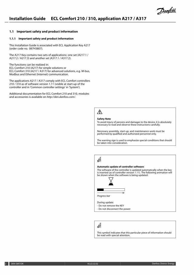
Safety NoteTo avoid injury of persons and damages to the device, it is absolutelynecessary to read and observe these instructions carefully.
Necessary assembly, start-up, and maintenance work must beperformed by qualified and authorized personnel only.
The warning sign is used to emphasize special conditions that shouldbe taken into consideration.
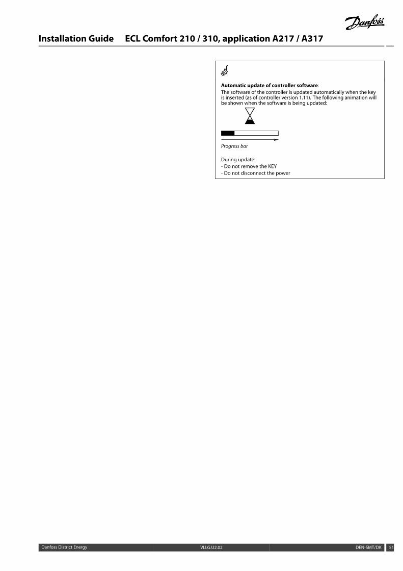
Automatic update of controller software:The software of the controller is updated automatically when the keyis inserted (as of controller version 1.11). The following animation willbe shown when the software is being updated:
Progress bar
During update:- Do not remove the KEY- Do not disconnect the power
This symbol indicates that this particular piece of information shouldbe read with special attention.
2 DEN-SMT/DK VI.LG.U2.02 Danfoss District Energy
Installation Guide ECL Comfort 210 / 310, application A217 / A317
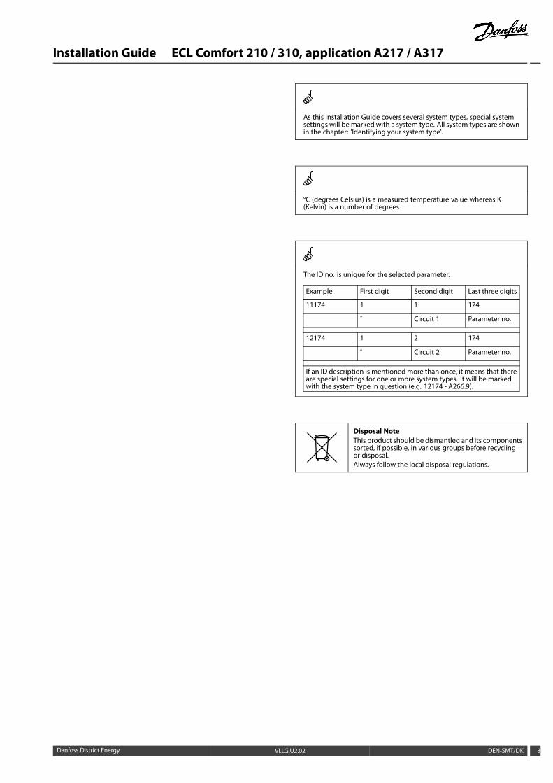
As this Installation Guide covers several system types, special systemsettings will be marked with a system type. All system types are shownin the chapter: 'Identifying your system type'.
°C (degrees Celsius) is a measured temperature value whereas K(Kelvin) is a number of degrees.
The ID no. is unique for the selected parameter.
Example First digit Second digit Last three digits
11174 1 1 174
- Circuit 1 Parameter no.
12174 1 2 174
- Circuit 2 Parameter no.
If an ID description is mentionedmore than once, it means that thereare special settings for one or more system types. It will be markedwith the system type in question (e.g. 12174 - A266.9).
Disposal NoteThis product should be dismantled and its componentssorted, if possible, in various groups before recyclingor disposal.Always follow the local disposal regulations.
Danfoss District Energy VI.LG.U2.02 DEN-SMT/DK 3
Installation Guide ECL Comfort 210 / 310, application A217 / A317
2.0 Installation
2.1 Before you start
The two applications, A217.1 / A317.1 are almost identical.However, A317.1 has some extra functions which are describedseparately.
The applications A217.1 / A317.1 are very flexible. These are thebasic principles:
Domestic Hot Water (DHW):
By means of a week schedule (up to 3 ‘Comfort’ periods / day), theDHW circuit can be in ‘Comfort’ or ‘Saving’ mode (two differenttemperature values for the desired DHW temperature at S6).
The heating / charging temperature sensor S3 is the mostimportant sensor.
If the measured DHW temperature (S6) gets lower than the desiredDHW temperature, the DHW heating / charging pump (P1) isswitched ON.
The motorized control valve (M1) is controlled in order to maintainthe heating / charging temperature at S3. This temperature istypically 5–10 degrees higher than the desired DHW temperature.A max. value can be set.
DHW tank with 1 temperature sensor (S6):If the measured DHW temperature (S6) gets higher than thedesired DHW temperature, the DHW heating / charging pump (P1)is switched OFF. The post-run time can be set.
DHW tank with 2 temperature sensors (S6 and S8):If themeasured DHW temperature (S6) gets higher than the desiredDHW temperature and the lower temperature (at S8) gets higherthan the cut-out temperature, the DHW heating / charging pump(P1) is switched OFF. The post-run time can be set.
In charging applications the DHW circulation can be throughthe DHW tank (connection A) or through the heat-exchanger(connection B).
The solution with connection A results in closing of the motorizedcontrol valve after the DHW tank charging procedure.The solution with connection B is used to compensate for theheat loss in the DHW circulation pipe. Furthermore, after DHWtank charging, the circulation temperature (at S3) is controlledaccording to the desired DHW temperature.
The return temperature (S5) to the district heating supply shouldnot be too high. If so, the desired charging temperature can beadjusted (typically to a lower value), thus resulting in a gradualclosing of the motorized control valve.
In boiler-based heating supply the return temperature should notbe too low (same adjustment procedure as above).
The supply temperature, S2, is used for adjusting the proportionalband (Xp) in order to give a stable temperature control.
An anti-bacteria function is available for activation on selecteddays of the week.
The outdoor temperature sensor S1 is used to protect thecirculation circuit against frost.
The DHW circulation pump (P3) has a week schedule for up to 3ON-periods per day.
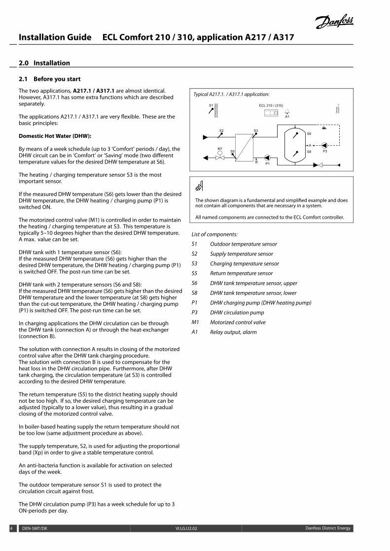
Typical A217.1. / A317.1 application:
S1
Dan
foss
87H
2067
.11ECL 210 / (310)
M1
A1
P1
S3
S5
S6
S8 P3
A
B
S2
The shown diagram is a fundamental and simplified example and doesnot contain all components that are necessary in a system.
All named components are connected to the ECL Comfort controller.
List of components:
S1 Outdoor temperature sensor
S2 Supply temperature sensor
S3 Charging temperature sensor
S5 Return temperature sensor
S6 DHW tank temperature sensor, upper
S8 DHW tank temperature sensor, lower
P1 DHW charging pump (DHW heating pump)
P3 DHW circulation pump
M1 Motorized control valve
A1 Relay output, alarm
4 DEN-SMT/DK VI.LG.U2.02 Danfoss District Energy
Installation Guide ECL Comfort 210 / 310, application A217 / A317
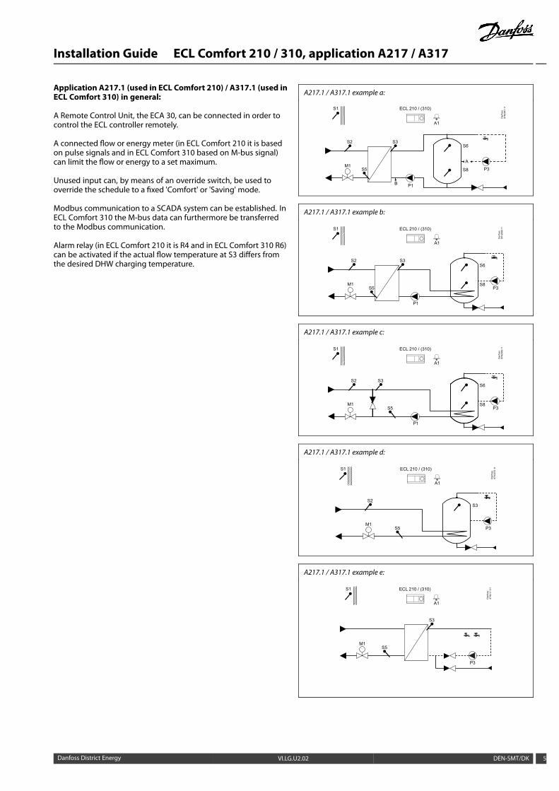
Application A217.1 (used in ECL Comfort 210) / A317.1 (used inECL Comfort 310) in general:
A Remote Control Unit, the ECA 30, can be connected in order tocontrol the ECL controller remotely.
A connected flow or energy meter (in ECL Comfort 210 it is basedon pulse signals and in ECL Comfort 310 based on M-bus signal)can limit the flow or energy to a set maximum.
Unused input can, by means of an override switch, be used tooverride the schedule to a fixed 'Comfort' or 'Saving' mode.
Modbus communication to a SCADA system can be established. InECL Comfort 310 the M-bus data can furthermore be transferredto the Modbus communication.
Alarm relay (in ECL Comfort 210 it is R4 and in ECL Comfort 310 R6)can be activated if the actual flow temperature at S3 differs fromthe desired DHW charging temperature.
A217.1 / A317.1 example a:
S1
Dan
foss
87H
2067
.11ECL 210 / (310)
M1
A1
P1
S3
S5
S6
S8 P3
A
B
S2
A217.1 / A317.1 example b:
S1
Dan
foss
87H
2068
.11ECL 210 / (310)
M1
A1
S3
S5
S6
P3S8
P1
S2
A217.1 / A317.1 example c:
S1
Dan
foss
87H
2069
.11ECL 210 / (310)
M1
A1
S3
S5
S6
P3S8
P1
S2
A217.1 / A317.1 example d:
S1
Dan
foss
87H
2070
.11ECL 210 / (310)
M1
A1
S5
S3
P3
S2
A217.1 / A317.1 example e:
M1
S3
S5
P3
S1
Dan
foss
87H
2111
.11ECL 210 / (310)
A1
Danfoss District Energy VI.LG.U2.02 DEN-SMT/DK 5

Installation Guide ECL Comfort 210 / 310, application A217 / A317
The two applications, A217.2 / A317.2 are almost identical.However, A317.2 has some extra functions which are describedseparately.
The applications A217.2 / A317.2 are very flexible. These are thebasic principles:
Domestic Hot Water (DHW):
By means of a week schedule (up to 3 ‘Comfort’ periods / day), theDHW circuit can be in ‘Comfort’ or ‘Saving’ mode (two differenttemperature values for the desired DHW temperature at S6).
The DHW heating temperature sensor S3 and the chargingtemperature sensor S4 are the most important sensors.
If the measured DHW temperature (S6) gets lower than the desiredDHW temperature, the DHWheating pump (P1) is switched ON. Themotorized control valve (M1) is controlled in order to maintain theDHW heating temperature at S3. The DHW heating temperature isdetermined by the desired DHW charging temperature at S4.
When the DHW heating temperature is reached, the DHW chargingpump P2 is switched ON.
If the DHW charging temperature at S4 can not be reached, theECL controller gradually increases the desired DHW heatingtemperature at S3 in order to obtain the charging temperature.A max. value can be set.
The DHW charging temperature at S4 is typically 5–10 degreeshigher than the desired DHW temperature.
DHW tank with 1 temperature sensor (S6):If themeasured DHW temperature (S6) gets higher than the desiredDHW temperature, the DHW heating pump (P1) and the DHWcharging pump (P2) are switched OFF. The post-run time can be set.
DHW tank with 2 temperature sensors (S6 and S8):If the measured DHW temperature (S6) gets higher than thedesired DHW temperature and the lower temperature (at S8) getshigher than the cut-out temperature, the DHW heating pump (P1)and the DHW charging pump (P2) are switched OFF. The post-runtime can be set.
In charging applications the DHW circulation can be throughthe DHW tank (connection A) or through the heat-exchanger(connection B).The solution with connection A results in closing of the motorizedcontrol valve after the DHW tank charging procedure.The solution with connection B is used to compensate for the heatloss in the DHW circulation pipe.Furthermore, after DHW tank charging, the circulation temperature(at S4) is controlled according to the desired DHW temperature.
Typical A217.2. / A317.2 application:
S1
Dan
foss
87H
2071
.11ECL 210 / (310)
M1
A1
P2
S4
S5
S6
S8 P3
A
B
S2 S3
P1
The shown diagram is a fundamental and simplified example and doesnot contain all components that are necessary in a system.
All named components are connected to the ECL Comfort controller.
List of components:
S1 Outdoor temperature sensor
S2 Supply temperature sensor
S3 DHW heating temperature sensor
S4 DHW charging temperature sensor
S5 Return temperature sensor
S6 DHW tank temperature sensor, upper
S8 DHW tank temperature sensor, lower
P1 DHW heating pump
P2 DHW charging pump
P3 DHW circulation pump
M1 Motorized control valve
A1 Relay output, alarm
6 DEN-SMT/DK VI.LG.U2.02 Danfoss District Energy
Installation Guide ECL Comfort 210 / 310, application A217 / A317
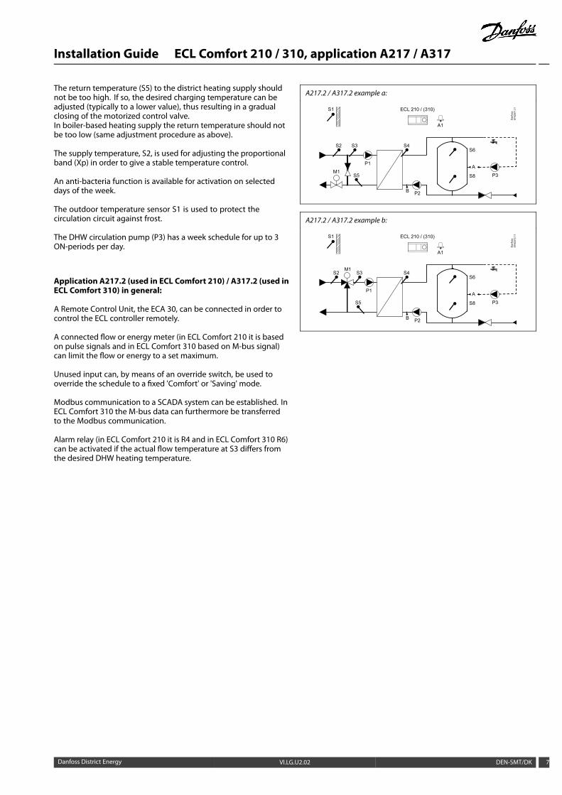
The return temperature (S5) to the district heating supply shouldnot be too high. If so, the desired charging temperature can beadjusted (typically to a lower value), thus resulting in a gradualclosing of the motorized control valve.In boiler-based heating supply the return temperature should notbe too low (same adjustment procedure as above).
The supply temperature, S2, is used for adjusting the proportionalband (Xp) in order to give a stable temperature control.
An anti-bacteria function is available for activation on selecteddays of the week.
The outdoor temperature sensor S1 is used to protect thecirculation circuit against frost.
The DHW circulation pump (P3) has a week schedule for up to 3ON-periods per day.
Application A217.2 (used in ECL Comfort 210) / A317.2 (used inECL Comfort 310) in general:
A Remote Control Unit, the ECA 30, can be connected in order tocontrol the ECL controller remotely.
A connected flow or energy meter (in ECL Comfort 210 it is basedon pulse signals and in ECL Comfort 310 based on M-bus signal)can limit the flow or energy to a set maximum.
Unused input can, by means of an override switch, be used tooverride the schedule to a fixed 'Comfort' or 'Saving' mode.
Modbus communication to a SCADA system can be established. InECL Comfort 310 the M-bus data can furthermore be transferredto the Modbus communication.
Alarm relay (in ECL Comfort 210 it is R4 and in ECL Comfort 310 R6)can be activated if the actual flow temperature at S3 differs fromthe desired DHW heating temperature.
A217.2 / A317.2 example a:
S1
Dan
foss
87H
2071
.11ECL 210 / (310)
M1
A1
P2
S4
S5
S6
S8 P3
A
B
S2 S3
P1
A217.2 / A317.2 example b:
S1
Dan
foss
87H
2072
.11ECL 210 / (310)
M1
A1
P2
S4
S5
S6
S8 P3
A
B
S2 S3
P1
Danfoss District Energy VI.LG.U2.02 DEN-SMT/DK 7
Installation Guide ECL Comfort 210 / 310, application A217 / A317
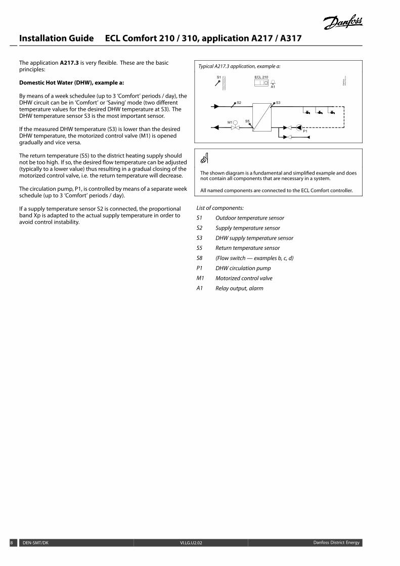
The application A217.3 is very flexible. These are the basicprinciples:
Domestic Hot Water (DHW), example a:
By means of a week schedulee (up to 3 ‘Comfort’ periods / day), theDHW circuit can be in ‘Comfort’ or ‘Saving’ mode (two differenttemperature values for the desired DHW temperature at S3). TheDHW temperature sensor S3 is the most important sensor.
If the measured DHW temperature (S3) is lower than the desiredDHW temperature, the motorized control valve (M1) is openedgradually and vice versa.
The return temperature (S5) to the district heating supply shouldnot be too high. If so, the desired flow temperature can be adjusted(typically to a lower value) thus resulting in a gradual closing of themotorized control valve, i.e. the return temperature will decrease.
The circulation pump, P1, is controlled bymeans of a separate weekschedule (up to 3 ‘Comfort’ periods / day).
If a supply temperature sensor S2 is connected, the proportionalband Xp is adapted to the actual supply temperature in order toavoid control instability.
Typical A217.3 application, example a:
The shown diagram is a fundamental and simplified example and doesnot contain all components that are necessary in a system.
All named components are connected to the ECL Comfort controller.
List of components:
S1 Outdoor temperature sensor
S2 Supply temperature sensor
S3 DHW supply temperature sensor
S5 Return temperature sensor
S8 (Flow switch— examples b, c, d)
P1 DHW circulation pump
M1 Motorized control valve
A1 Relay output, alarm
8 DEN-SMT/DK VI.LG.U2.02 Danfoss District Energy

Installation Guide ECL Comfort 210 / 310, application A217 / A317
Example b:A flow switch signal (S8) can be applied in order to heat the DHWon demand (DHW tapping / DHW draw-off ). An idle temperaturefor the supply temperature (at S2) can be maintained to minimizethe heat-up time for the DHW.
Example c:A flow switch signal (S8) can be applied in order to heat the DHWon demand (DHW tapping / DHW draw-off ). The temperature atS3 is maintained during the comfort times of the circulation pumpP1. An idle temperature for the supply temperature (at S2) can bemaintained to minimize the heat-up time for the DHW.
Example d:The DHW tank is directly heated. The setting of the returntemperature limitation (at S5) can avoid a too high flow in theheating coil. An idle temperature for the supply temperature (atS2) can be maintained to minimize the heat-up time for the DHW.
A217.3 example a:
A217.3 example b:
A217.3 example c:
A217.3 example d:
The controller is pre-programmed with factory settings that are shownin the relevant chapters of this guide.
Danfoss District Energy VI.LG.U2.02 DEN-SMT/DK 9
Installation Guide ECL Comfort 210 / 310, application A217 / A317
2.2 Identifying the system type
Sketch your application
The ECL Comfort controller series is designed for a wide rangeof heating, domestic hot-water (DHW) and cooling systems withdifferent configurations and capacities. If your system differsfrom the diagrams shown here, you may want to make a sketchof the system about to be installed. This makes it easier to usethe Installation Guide, which will guide you step-by-step frominstallation to final adjustments before the end-user takes over.
The ECL Comfort controller is a universal controller that can beused for various systems. Based on the shown standard systems,it is possible to configure additional systems. In this chapter youfind the most frequently used systems. If your system is not quiteas shown below, find the diagram which has the best resemblancewith your system and make your own combinations.
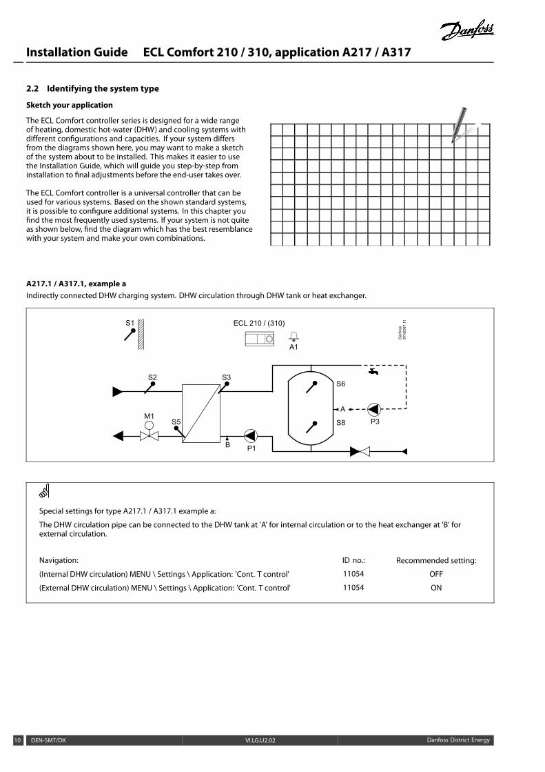
A217.1 / A317.1, example aIndirectly connected DHW charging system. DHW circulation through DHW tank or heat exchanger.
S1
Dan
foss
87H
2067
.11ECL 210 / (310)
M1
A1
P1
S3
S5
S6
S8 P3
A
B
S2
Special settings for type A217.1 / A317.1 example a:
The DHW circulation pipe can be connected to the DHW tank at 'A' for internal circulation or to the heat exchanger at 'B' forexternal circulation.
Navigation: ID no.: Recommended setting:
(Internal DHW circulation) MENU \ Settings \ Application: 'Cont. T control' 11054 OFF
(External DHW circulation) MENU \ Settings \ Application: 'Cont. T control' 11054 ON
10 DEN-SMT/DK VI.LG.U2.02 Danfoss District Energy
Installation Guide ECL Comfort 210 / 310, application A217 / A317
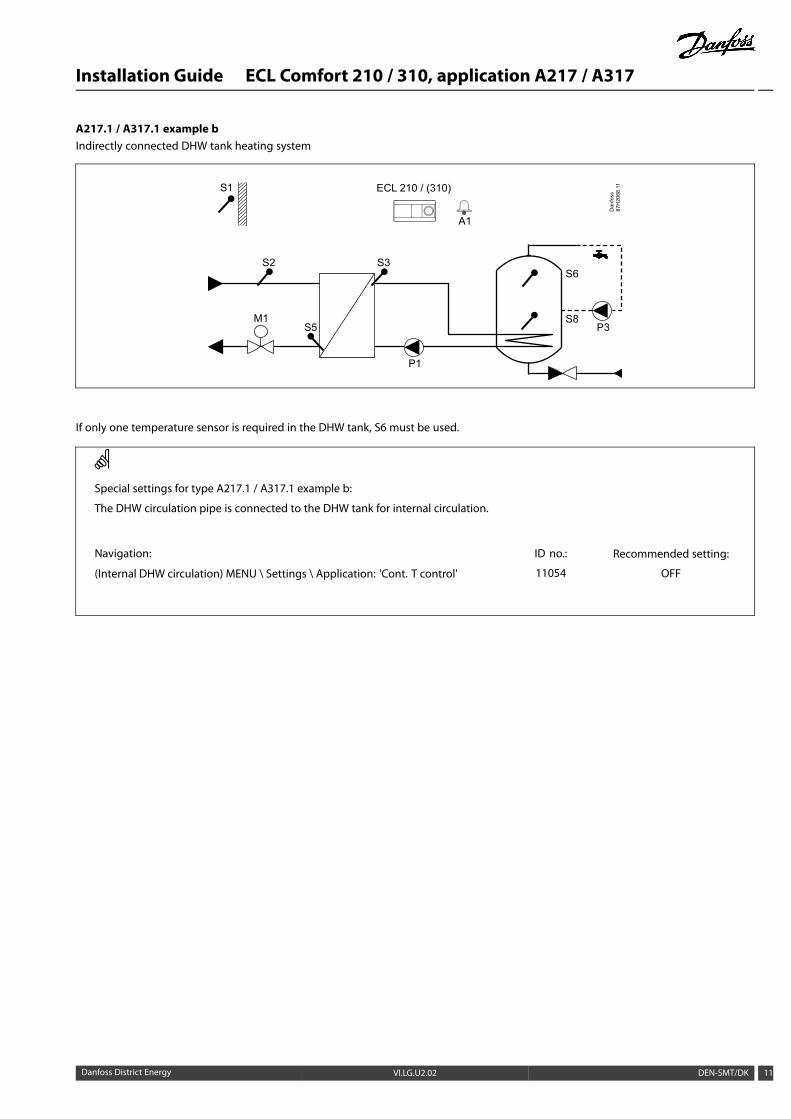
A217.1 / A317.1 example bIndirectly connected DHW tank heating system
S1
Dan
foss
87H
2068
.11ECL 210 / (310)
M1
A1
S3
S5
S6
P3S8
P1
S2
If only one temperature sensor is required in the DHW tank, S6 must be used.
Special settings for type A217.1 / A317.1 example b:
The DHW circulation pipe is connected to the DHW tank for internal circulation.
Navigation: ID no.: Recommended setting:
(Internal DHW circulation) MENU \ Settings \ Application: 'Cont. T control' 11054 OFF
Danfoss District Energy VI.LG.U2.02 DEN-SMT/DK 11
Installation Guide ECL Comfort 210 / 310, application A217 / A317
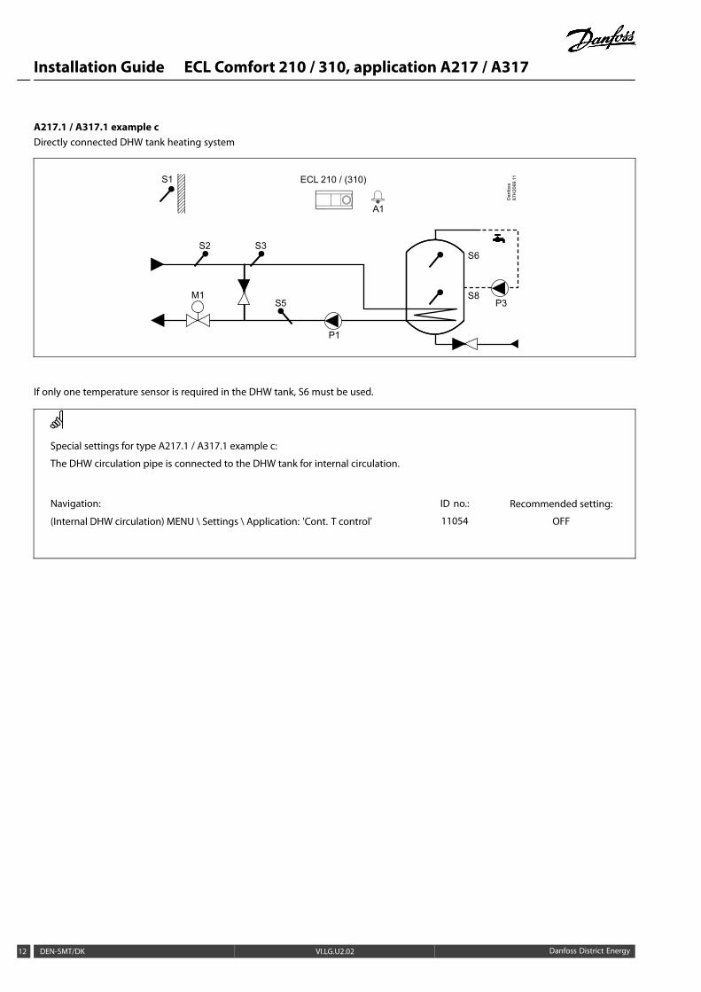
A217.1 / A317.1 example cDirectly connected DHW tank heating system
S1
Dan
foss
87H
2069
.11ECL 210 / (310)
M1
A1
S3
S5
S6
P3S8
P1
S2
If only one temperature sensor is required in the DHW tank, S6 must be used.
Special settings for type A217.1 / A317.1 example c:
The DHW circulation pipe is connected to the DHW tank for internal circulation.
Navigation: ID no.: Recommended setting:
(Internal DHW circulation) MENU \ Settings \ Application: 'Cont. T control' 11054 OFF
12 DEN-SMT/DK VI.LG.U2.02 Danfoss District Energy

Installation Guide ECL Comfort 210 / 310, application A217 / A317
A217.1 / A317.1 example dDirectly connected DHW tank heating system
S1
Dan
foss
87H
2070
.11ECL 210 / (310)
M1
A1
S5
S3
P3
S2
When the circulation pump P3 is in comfort mode, the temperature at S3 can be controlled.
Special settings for type A217.1 / A317.1 example d:
Navigation: ID no.: Recommended setting:
MENU \ Settings \ Application: 'Cont. T control' 11054 ON
Danfoss District Energy VI.LG.U2.02 DEN-SMT/DK 13
Installation Guide ECL Comfort 210 / 310, application A217 / A317
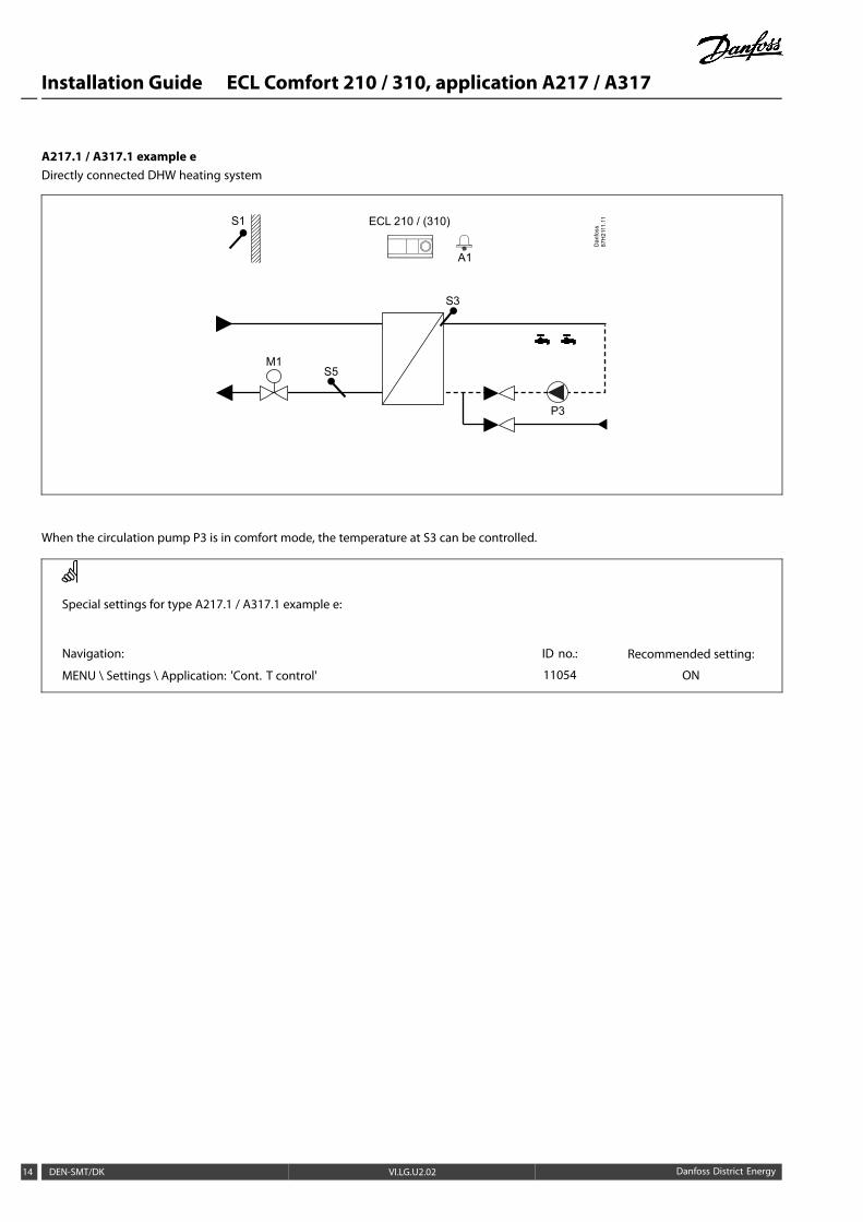
A217.1 / A317.1 example eDirectly connected DHW heating system
M1
S3
S5
P3
S1
Dan
foss
87H
2111
.11ECL 210 / (310)
A1
When the circulation pump P3 is in comfort mode, the temperature at S3 can be controlled.
Special settings for type A217.1 / A317.1 example e:
Navigation: ID no.: Recommended setting:
MENU \ Settings \ Application: 'Cont. T control' 11054 ON
14 DEN-SMT/DK VI.LG.U2.02 Danfoss District Energy
Installation Guide ECL Comfort 210 / 310, application A217 / A317
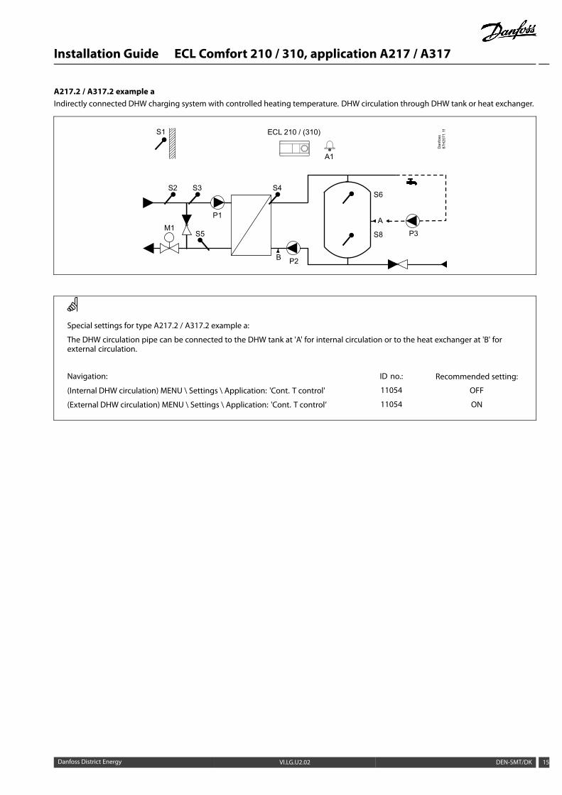
A217.2 / A317.2 example aIndirectly connected DHW charging system with controlled heating temperature. DHW circulation through DHW tank or heat exchanger.
S1
Dan
foss
87H
2071
.11ECL 210 / (310)
M1
A1
P2
S4
S5
S6
S8 P3
A
B
S2 S3
P1
Special settings for type A217.2 / A317.2 example a:
The DHW circulation pipe can be connected to the DHW tank at 'A' for internal circulation or to the heat exchanger at 'B' forexternal circulation.
Navigation: ID no.: Recommended setting:
(Internal DHW circulation) MENU \ Settings \ Application: 'Cont. T control' 11054 OFF
(External DHW circulation) MENU \ Settings \ Application: 'Cont. T control’ 11054 ON
Danfoss District Energy VI.LG.U2.02 DEN-SMT/DK 15

Installation Guide ECL Comfort 210 / 310, application A217 / A317
A217.2 / A317.2 example bIndirectly connected DHW charging system with controlled heating temperature. DHW circulation through DHW tank or heat exchanger.
S1
Dan
foss
87H
2072
.11ECL 210 / (310)
M1
A1
P2
S4
S5
S6
S8 P3
A
B
S2 S3
P1
Special settings for type A217.2 / A317.2 example b:
The DHW circulation pipe can be connected to the DHW tank at 'A' for internal circulation or to the heat exchanger at 'B' forexternal circulation.
Navigation: ID no.: Recommended setting:
(Internal DHW circulation) MENU \ Settings \ Application: 'Cont. T control' 11054 OFF
(External DHW circulation) MENU \ Settings \ Application: 'Cont. T control’ 11054 ON
16 DEN-SMT/DK VI.LG.U2.02 Danfoss District Energy
Installation Guide ECL Comfort 210 / 310, application A217 / A317
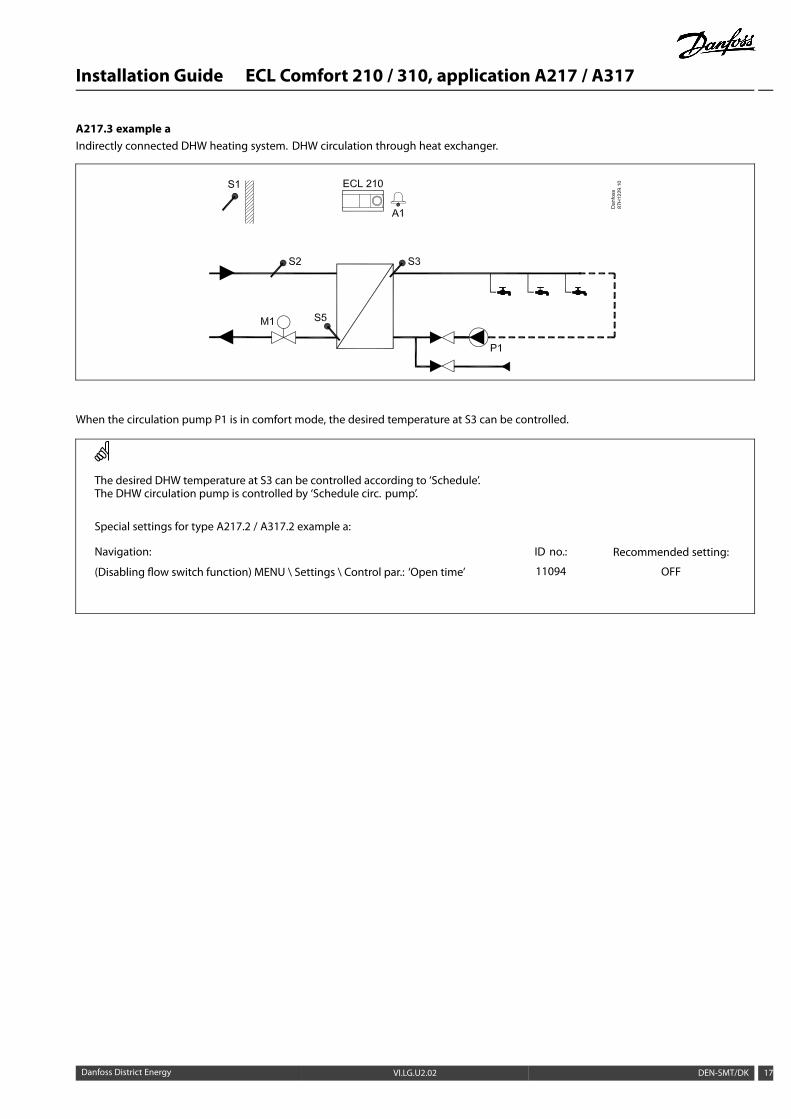
A217.3 example aIndirectly connected DHW heating system. DHW circulation through heat exchanger.
When the circulation pump P1 is in comfort mode, the desired temperature at S3 can be controlled.
The desired DHW temperature at S3 can be controlled according to ‘Schedule’.The DHW circulation pump is controlled by ‘Schedule circ. pump’.
Special settings for type A217.2 / A317.2 example a:
Navigation: ID no.: Recommended setting:
(Disabling flow switch function) MENU \ Settings \ Control par.: ‘Open time’ 11094 OFF
Danfoss District Energy VI.LG.U2.02 DEN-SMT/DK 17
Installation Guide ECL Comfort 210 / 310, application A217 / A317
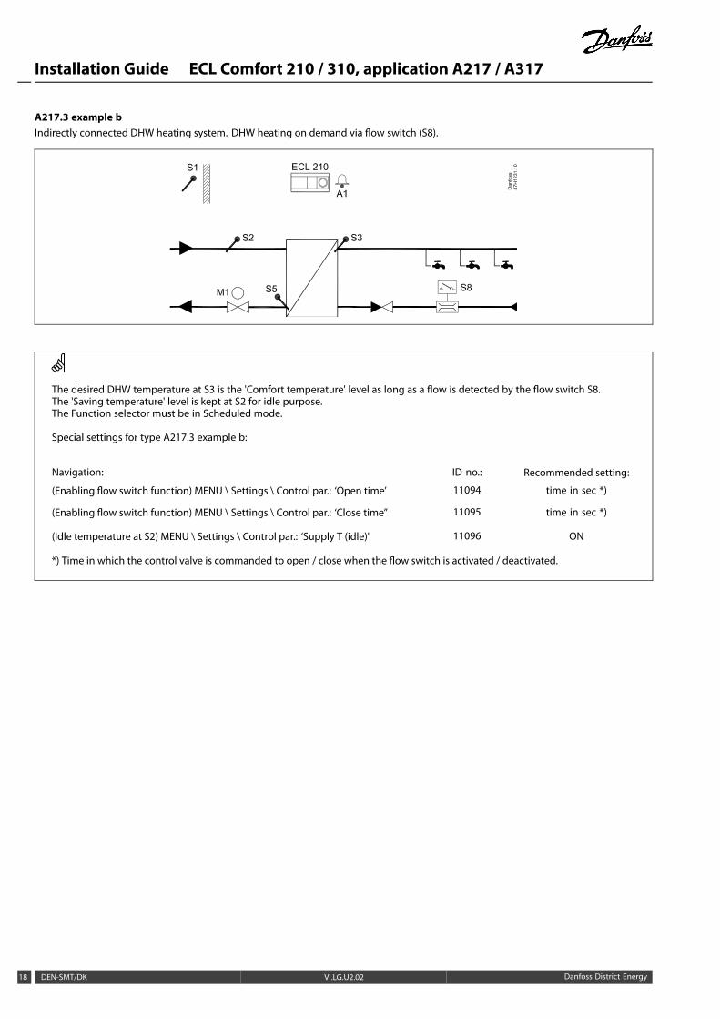
A217.3 example bIndirectly connected DHW heating system. DHW heating on demand via flow switch (S8).
The desired DHW temperature at S3 is the 'Comfort temperature' level as long as a flow is detected by the flow switch S8.The 'Saving temperature' level is kept at S2 for idle purpose.The Function selector must be in Scheduled mode.
Special settings for type A217.3 example b:
Navigation: ID no.: Recommended setting:
(Enabling flow switch function) MENU \ Settings \ Control par.: ‘Open time’ 11094 time in sec *)
(Enabling flow switch function) MENU \ Settings \ Control par.: ‘Close time’’ 11095 time in sec *)
(Idle temperature at S2) MENU \ Settings \ Control par.: ‘Supply T (idle)' 11096 ON
*) Time in which the control valve is commanded to open / close when the flow switch is activated / deactivated.
18 DEN-SMT/DK VI.LG.U2.02 Danfoss District Energy
Installation Guide ECL Comfort 210 / 310, application A217 / A317
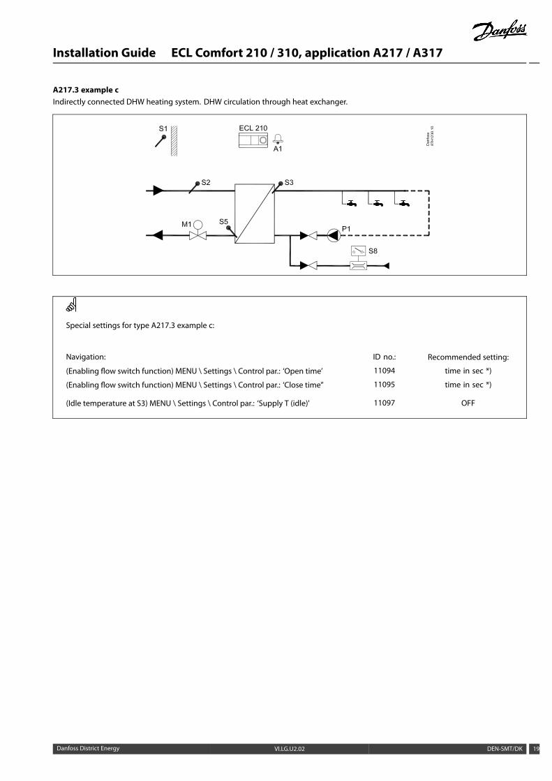
A217.3 example cIndirectly connected DHW heating system. DHW circulation through heat exchanger.
Special settings for type A217.3 example c:
Navigation: ID no.: Recommended setting:
(Enabling flow switch function) MENU \ Settings \ Control par.: ‘Open time’ 11094 time in sec *)
(Enabling flow switch function) MENU \ Settings \ Control par.: ‘Close time’’ 11095 time in sec *)
(Idle temperature at S3) MENU \ Settings \ Control par.: ‘Supply T (idle)' 11097 OFF
Danfoss District Energy VI.LG.U2.02 DEN-SMT/DK 19
Installation Guide ECL Comfort 210 / 310, application A217 / A317
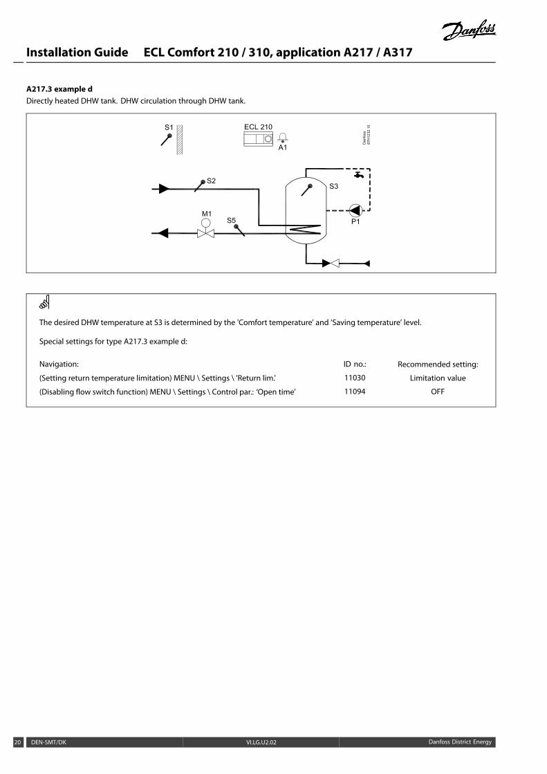
A217.3 example dDirectly heated DHW tank. DHW circulation through DHW tank.
The desired DHW temperature at S3 is determined by the 'Comfort temperature' and ‘Saving temperature’ level.
Special settings for type A217.3 example d:
Navigation: ID no.: Recommended setting:
(Setting return temperature limitation) MENU \ Settings \ 'Return lim.' 11030 Limitation value
(Disabling flow switch function) MENU \ Settings \ Control par.: ‘Open time’ 11094 OFF
20 DEN-SMT/DK VI.LG.U2.02 Danfoss District Energy
Installation Guide ECL Comfort 210 / 310, application A217 / A317
2.3 Mounting
2.3.1 Mounting the ECL Comfort controller
For easy access, you should mount the ECL Comfort controller nearthe system. Select one of the following methods using the samebase part (code no. 087H3230):
• Mounting on a wall
• Mounting on a DIN rail (35 mm)
The ECL Comfort 310 can only be mounted in the ECL Comfort310 base part.
Screws, PG cable glands and rawlplugs are not supplied.
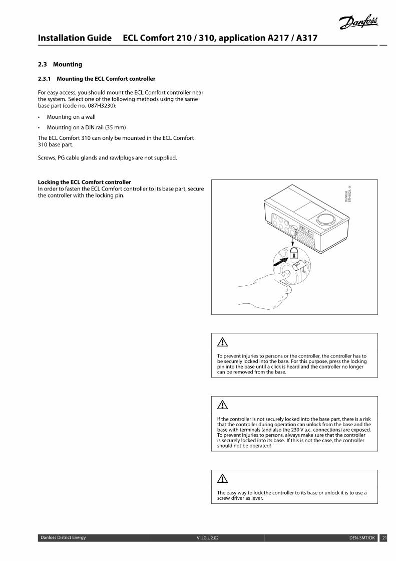
Locking the ECL Comfort controllerIn order to fasten the ECL Comfort controller to its base part, securethe controller with the locking pin.
To prevent injuries to persons or the controller, the controller has tobe securely locked into the base. For this purpose, press the lockingpin into the base until a click is heard and the controller no longercan be removed from the base.
If the controller is not securely locked into the base part, there is a riskthat the controller during operation can unlock from the base and thebase with terminals (and also the 230 V a.c. connections) are exposed.To prevent injuries to persons, always make sure that the controlleris securely locked into its base. If this is not the case, the controllershould not be operated!
The easy way to lock the controller to its base or unlock it is to use ascrew driver as lever.
Danfoss District Energy VI.LG.U2.02 DEN-SMT/DK 21
Installation Guide ECL Comfort 210 / 310, application A217 / A317
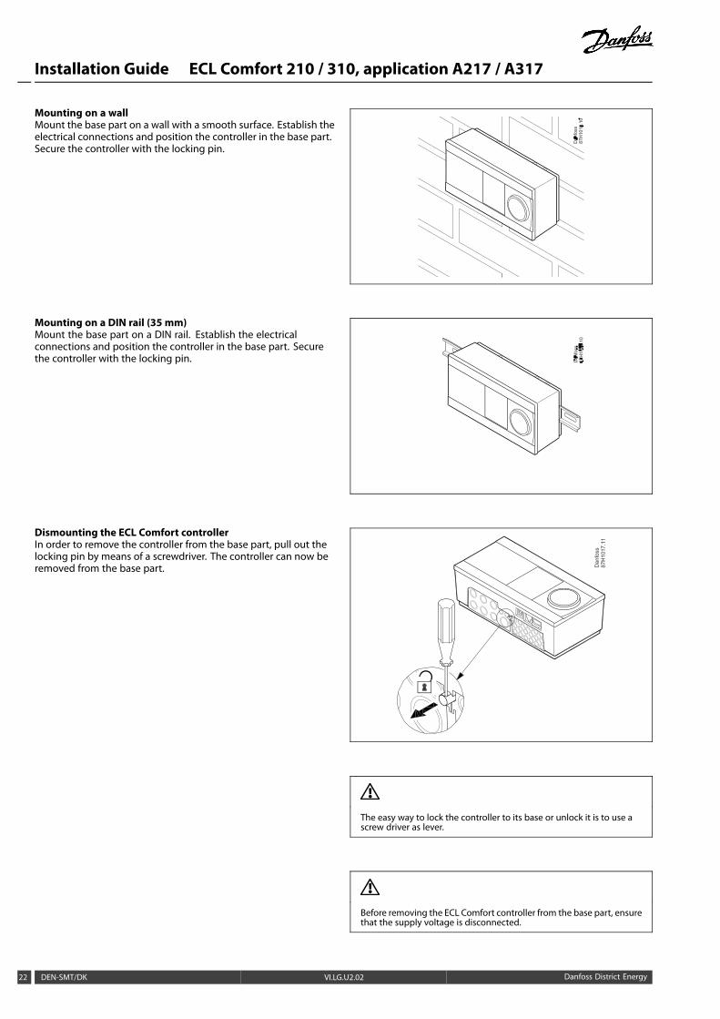
Mounting on a wallMount the base part on a wall with a smooth surface. Establish theelectrical connections and position the controller in the base part.Secure the controller with the locking pin.
Mounting on a DIN rail (35 mm)Mount the base part on a DIN rail. Establish the electricalconnections and position the controller in the base part. Securethe controller with the locking pin.
Dismounting the ECL Comfort controllerIn order to remove the controller from the base part, pull out thelocking pin by means of a screwdriver. The controller can now beremoved from the base part.
The easy way to lock the controller to its base or unlock it is to use ascrew driver as lever.
Before removing the ECL Comfort controller from the base part, ensurethat the supply voltage is disconnected.
22 DEN-SMT/DK VI.LG.U2.02 Danfoss District Energy
Installation Guide ECL Comfort 210 / 310, application A217 / A317
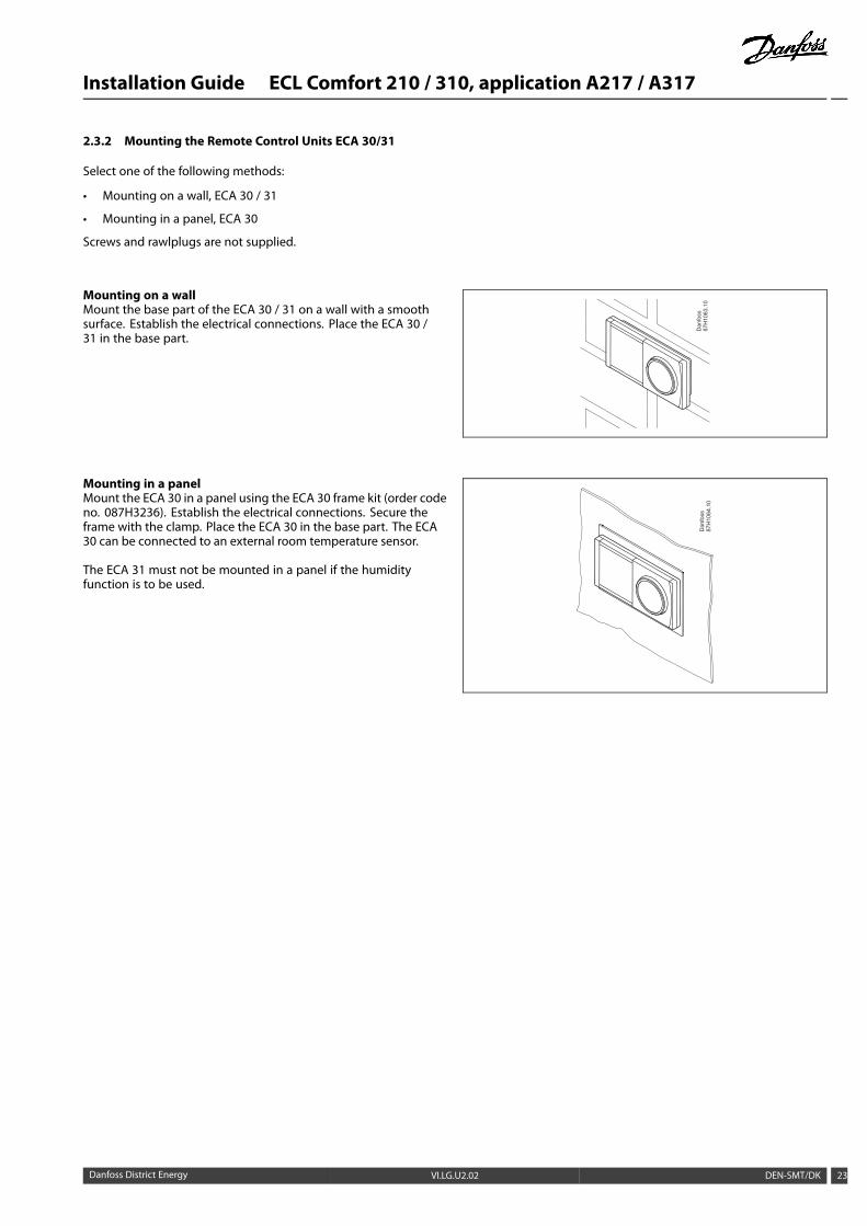
2.3.2 Mounting the Remote Control Units ECA 30/31
Select one of the following methods:
• Mounting on a wall, ECA 30 / 31
• Mounting in a panel, ECA 30
Screws and rawlplugs are not supplied.
Mounting on a wallMount the base part of the ECA 30 / 31 on a wall with a smoothsurface. Establish the electrical connections. Place the ECA 30 /31 in the base part.
Mounting in a panelMount the ECA 30 in a panel using the ECA 30 frame kit (order codeno. 087H3236). Establish the electrical connections. Secure theframe with the clamp. Place the ECA 30 in the base part. The ECA30 can be connected to an external room temperature sensor.
The ECA 31 must not be mounted in a panel if the humidityfunction is to be used.
Danfoss District Energy VI.LG.U2.02 DEN-SMT/DK 23
Installation Guide ECL Comfort 210 / 310, application A217 / A317
2.4 Placing the temperature sensors
2.4.1 Placing the temperature sensors
It is important that the sensors are mounted in the correct positionin your system.
The temperature sensor mentioned below are sensors used forthe ECL Comfort 210 and 310 series which not all will be neededfor your application!
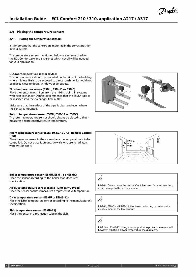
Outdoor temperature sensor (ESMT)The outdoor sensor should bemounted on that side of the buildingwhere it is less likely to be exposed to direct sunshine. It should notbe placed close to doors, windows or air outlets.
Flow temperature sensor (ESMU, ESM-11 or ESMC)Place the sensor max. 15 cm from the mixing point. In systemswith heat exchanger, Danfoss recommends that the ESMU-type tobe inserted into the exchanger flow outlet.
Make sure that the surface of the pipe is clean and even wherethe sensor is mounted.
Return temperature sensor (ESMU, ESM-11 or ESMC)The return temperature sensor should always be placed so that itmeasures a representative return temperature.
Room temperature sensor (ESM-10, ECA 30 / 31 Remote ControlUnit)Place the room sensor in the room where the temperature is to becontrolled. Do not place it on outside walls or close to radiators,windows or doors.
Boiler temperature sensor (ESMU, ESM-11 or ESMC)Place the sensor according to the boiler manufacturer’sspecification.
Air duct temperature sensor (ESMB-12 or ESMU types)Place the sensor so that it measures a representative temperature.
DHW temperature sensor (ESMU or ESMB-12)Place the DHW temperature sensor according to themanufacturer’sspecification.
Slab temperature sensor (ESMB-12)Place the sensor in a protection tube in the slab.
ESM-11: Do not move the sensor after it has been fastened in order toavoid damage to the sensor element.
ESM-11, ESMC and ESMB-12: Use heat conducting paste for quickmeasurement of the temperature.
ESMU and ESMB-12: Using a sensor pocket to protect the sensor will,however, result in a slower temperature measurement.
24 DEN-SMT/DK VI.LG.U2.02 Danfoss District Energy
Installation Guide ECL Comfort 210 / 310, application A217 / A317
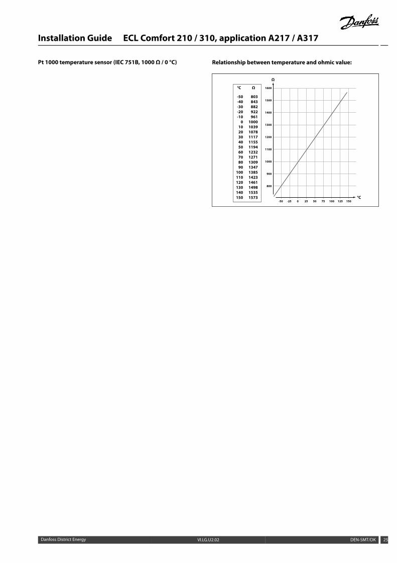
Pt 1000 temperature sensor (IEC 751B, 1000 Ω / 0 °C) Relationship between temperature and ohmic value:
-50
800
900
1000
1100
1200
1300
1400
1500
1600
-25 0 25 50 75 100 125 150°C
Ω
Ω
803843 882922961
1000103910781117115511941232127113091347138514231461149815351573
°C
-50 -40 -30-20-10 0102030405060708090
100110120130140150
Danfoss District Energy VI.LG.U2.02 DEN-SMT/DK 25

Installation Guide ECL Comfort 210 / 310, application A217 / A317
2.5 Electrical connections
2.5.1 Electrical connections 230 V a.c. in general
The common ground terminal is used for connection of relevantcomponents (pumps, motorized control valves).
26 DEN-SMT/DK VI.LG.U2.02 Danfoss District Energy
Installation Guide ECL Comfort 210 / 310, application A217 / A317
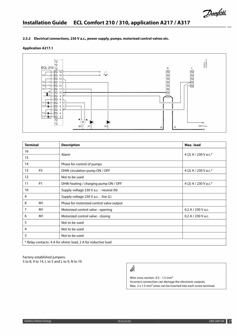
2.5.2 Electrical connections, 230 V a.c., power supply, pumps, motorized control valves etc.
Application A217.1
Dan
foss
87H
2082
.10
Terminal Description Max. load
16
15Alarm 4 (2) A / 230 V a.c.*
14 Phase for control of pumps
13 P3 DHW circulation pump ON / OFF 4 (2) A / 230 V a.c.*
12 Not to be used
11 P1 DHW heating / charging pump ON / OFF 4 (2) A / 230 V a.c.*
10 Supply voltage 230 V a.c. - neutral (N)
9 Supply voltage 230 V a.c. - live (L)
8 M1 Phase for motorized control valve output
7 M1 Motorized control valve - opening 0.2 A / 230 V a.c.
6 M1 Motorized control valve - closing 0.2 A / 230 V a.c.
5 Not to be used
4 Not to be used
3 Not to be used
* Relay contacts: 4 A for ohmic load, 2 A for inductive load
Factory established jumpers:5 to 8, 9 to 14, L to 5 and L to 9, N to 10
Wire cross section: 0.5 - 1.5 mm²Incorrect connection can damage the electronic outputs.Max. 2 x 1.5 mm² wires can be inserted into each screw terminal.
Danfoss District Energy VI.LG.U2.02 DEN-SMT/DK 27
Installation Guide ECL Comfort 210 / 310, application A217 / A317
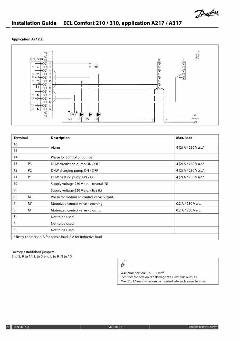
Application A217.2
Dan
foss
87H
2081
.10
Terminal Description Max. load
16
15Alarm 4 (2) A / 230 V a.c.*
14 Phase for control of pumps
13 P3 DHW circulation pump ON / OFF 4 (2) A / 230 V a.c.*
12 P2 DHW charging pump ON / OFF 4 (2) A / 230 V a.c.*
11 P1 DHW heating pump ON / OFF 4 (2) A / 230 V a.c.*
10 Supply voltage 230 V a.c. - neutral (N)
9 Supply voltage 230 V a.c. - live (L)
8 M1 Phase for motorized control valve output
7 M1 Motorized control valve - opening 0.2 A / 230 V a.c.
6 M1 Motorized control valve - closing 0.2 A / 230 V a.c.
5 Not to be used
4 Not to be used
3 Not to be used
* Relay contacts: 4 A for ohmic load, 2 A for inductive load
Factory established jumpers:5 to 8, 9 to 14, L to 5 and L to 9, N to 10
Wire cross section: 0.5 - 1.5 mm²Incorrect connection can damage the electronic outputs.Max. 2 x 1.5 mm² wires can be inserted into each screw terminal.
28 DEN-SMT/DK VI.LG.U2.02 Danfoss District Energy
Installation Guide ECL Comfort 210 / 310, application A217 / A317
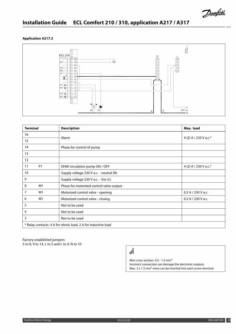
Application A217.3
Terminal Description Max. load
16
15Alarm 4 (2) A / 230 V a.c.*
14 Phase for control of pump
13
12
11 P1 DHW circulation pump ON / OFF 4 (2) A / 230 V a.c.*
10 Supply voltage 230 V a.c. - neutral (N)
9 Supply voltage 230 V a.c. - live (L)
8 M1 Phase for motorized control valve output
7 M1 Motorized control valve - opening 0.2 A / 230 V a.c.
6 M1 Motorized control valve - closing 0.2 A / 230 V a.c.
5 Not to be used
4 Not to be used
3 Not to be used
* Relay contacts: 4 A for ohmic load, 2 A for inductive load
Factory established jumpers:5 to 8, 9 to 14, L to 5 and L to 9, N to 10
Wire cross section: 0.5 - 1.5 mm²Incorrect connection can damage the electronic outputs.Max. 2 x 1.5 mm² wires can be inserted into each screw terminal.
Danfoss District Energy VI.LG.U2.02 DEN-SMT/DK 29
Installation Guide ECL Comfort 210 / 310, application A217 / A317
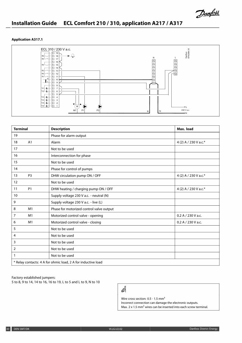
Application A317.1
ECL 310 / 230 V a.c.
Dan
foss
87H
2084
.10
Terminal Description Max. load
19 Phase for alarm output
18 A1 Alarm 4 (2) A / 230 V a.c.*
17 Not to be used
16 Interconnection for phase
15 Not to be used
14 Phase for control of pumps
13 P3 DHW circulation pump ON / OFF 4 (2) A / 230 V a.c.*
12 Not to be used
11 P1 DHW heating / charging pump ON / OFF 4 (2) A / 230 V a.c.*
10 Supply voltage 230 V a.c. - neutral (N)
9 Supply voltage 230 V a.c. - live (L)
8 M1 Phase for motorized control valve output
7 M1 Motorized control valve - opening 0.2 A / 230 V a.c.
6 M1 Motorized control valve - closing 0.2 A / 230 V a.c.
5 Not to be used
4 Not to be used
3 Not to be used
2 Not to be used
1 Not to be used
* Relay contacts: 4 A for ohmic load, 2 A for inductive load
Factory established jumpers:5 to 8, 9 to 14, 14 to 16, 16 to 19, L to 5 and L to 9, N to 10
Wire cross section: 0.5 - 1.5 mm²Incorrect connection can damage the electronic outputs.Max. 2 x 1.5 mm² wires can be inserted into each screw terminal.
30 DEN-SMT/DK VI.LG.U2.02 Danfoss District Energy
Installation Guide ECL Comfort 210 / 310, application A217 / A317
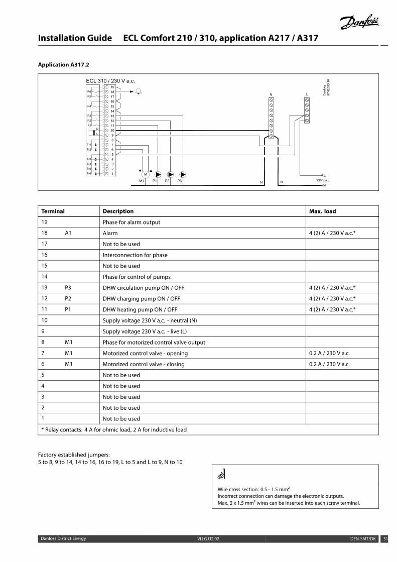
Application A317.2
ECL 310 / 230 V a.c.
Dan
foss
87H
2083
.10
Terminal Description Max. load
19 Phase for alarm output
18 A1 Alarm 4 (2) A / 230 V a.c.*
17 Not to be used
16 Interconnection for phase
15 Not to be used
14 Phase for control of pumps
13 P3 DHW circulation pump ON / OFF 4 (2) A / 230 V a.c.*
12 P2 DHW charging pump ON / OFF 4 (2) A / 230 V a.c.*
11 P1 DHW heating pump ON / OFF 4 (2) A / 230 V a.c.*
10 Supply voltage 230 V a.c. - neutral (N)
9 Supply voltage 230 V a.c. - live (L)
8 M1 Phase for motorized control valve output
7 M1 Motorized control valve - opening 0.2 A / 230 V a.c.
6 M1 Motorized control valve - closing 0.2 A / 230 V a.c.
5 Not to be used
4 Not to be used
3 Not to be used
2 Not to be used
1 Not to be used
* Relay contacts: 4 A for ohmic load, 2 A for inductive load
Factory established jumpers:5 to 8, 9 to 14, 14 to 16, 16 to 19, L to 5 and L to 9, N to 10
Wire cross section: 0.5 - 1.5 mm²Incorrect connection can damage the electronic outputs.Max. 2 x 1.5 mm² wires can be inserted into each screw terminal.
Danfoss District Energy VI.LG.U2.02 DEN-SMT/DK 31
Installation Guide ECL Comfort 210 / 310, application A217 / A317
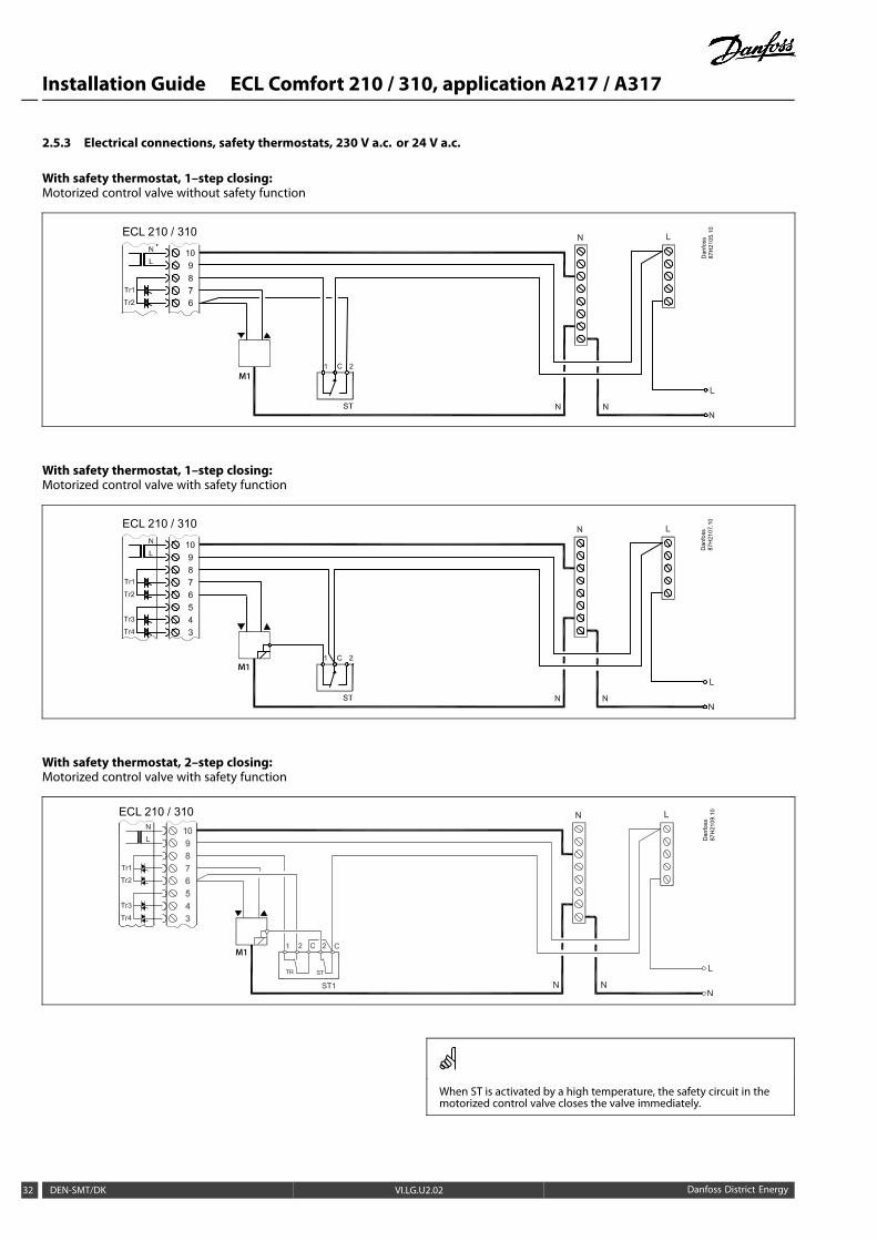
2.5.3 Electrical connections, safety thermostats, 230 V a.c. or 24 V a.c.
With safety thermostat, 1–step closing:Motorized control valve without safety function
Dan
foss
87H
2105
.10ECL 210 / 310
M1
With safety thermostat, 1–step closing:Motorized control valve with safety function
Dan
foss
87H
2107
.10ECL 210 / 310
M1
With safety thermostat, 2–step closing:Motorized control valve with safety function
ECL 210 / 310
Dan
foss
87H
2109
.10
M1
When ST is activated by a high temperature, the safety circuit in themotorized control valve closes the valve immediately.
32 DEN-SMT/DK VI.LG.U2.02 Danfoss District Energy
Installation Guide ECL Comfort 210 / 310, application A217 / A317
When ST1 is activated by a high temperature (the TR temperature), themotorized control valve is closed gradually. At a higher temperature(the ST temperature), the safety circuit in the motorized control valvecloses the valve immediately.
Wire cross section: 0.5 - 1.5 mm²Incorrect connection can damage the electronic outputs.Max. 2 x 1.5 mm² wires can be inserted into each screw terminal.
Danfoss District Energy VI.LG.U2.02 DEN-SMT/DK 33
Installation Guide ECL Comfort 210 / 310, application A217 / A317
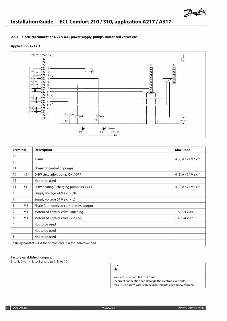
2.5.4 Electrical connections, 24 V a.c., power supply, pumps, motorized valves etc.
Application A217.1
Dan
foss
87H
2086
.10
Terminal Description Max. load
16
15Alarm 4 (2) A / 24 V a.c.*
14 Phase for control of pumps
13 K3 DHW circulation pump ON / OFF 4 (2) A / 24 V a.c.*
12 Not to be used
11 K1 DHW heating / charging pump ON / OFF 4 (2) A / 24 V a.c.*
10 Supply voltage 24 V a.c. - (N)
9 Supply voltage 24 V a.c. - (L)
8 M1 Phase for motorized control valve output
7 M1 Motorized control valve - opening 1 A / 24 V a.c.
6 M1 Motorized control valve - closing 1 A / 24 V a.c.
5 Not to be used
4 Not to be used
3 Not to be used
* Relay contacts: 4 A for ohmic load, 2 A for inductive load
Factory established jumpers:5 to 8, 9 to 14, L to 5 and L to 9, N to 10
Wire cross section: 0.5 - 1.5 mm²Incorrect connection can damage the electronic outputs.Max. 2 x 1.5 mm² wires can be inserted into each screw terminal.
34 DEN-SMT/DK VI.LG.U2.02 Danfoss District Energy

Installation Guide ECL Comfort 210 / 310, application A217 / A317
Do not connect 230 V a.c. powered components to a 24 V a.c. powersupplied controller directly. Use auxilliary relays (K) to separate 230V a.c. from 24 V a.c.
Danfoss District Energy VI.LG.U2.02 DEN-SMT/DK 35
Installation Guide ECL Comfort 210 / 310, application A217 / A317
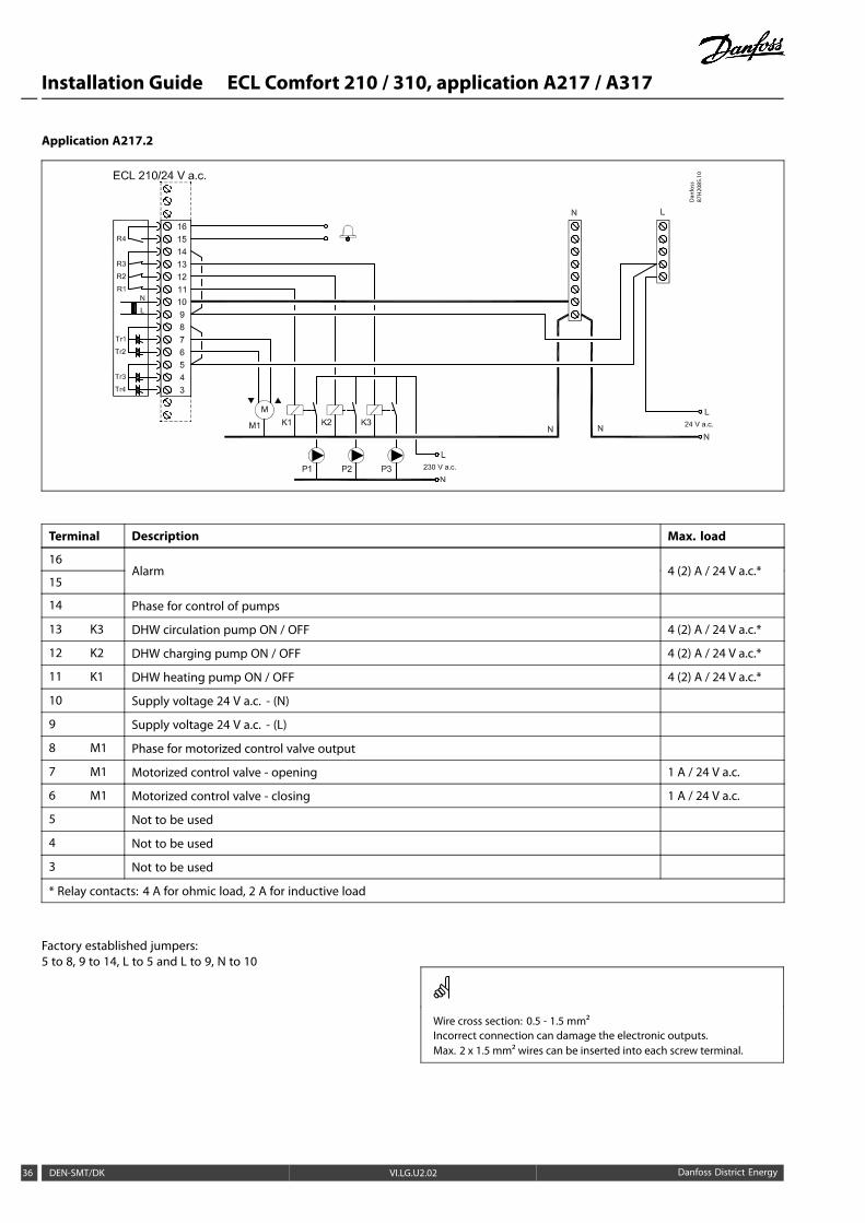
Application A217.2
Dan
foss
87H
2085
.10
Terminal Description Max. load
16
15Alarm 4 (2) A / 24 V a.c.*
14 Phase for control of pumps
13 K3 DHW circulation pump ON / OFF 4 (2) A / 24 V a.c.*
12 K2 DHW charging pump ON / OFF 4 (2) A / 24 V a.c.*
11 K1 DHW heating pump ON / OFF 4 (2) A / 24 V a.c.*
10 Supply voltage 24 V a.c. - (N)
9 Supply voltage 24 V a.c. - (L)
8 M1 Phase for motorized control valve output
7 M1 Motorized control valve - opening 1 A / 24 V a.c.
6 M1 Motorized control valve - closing 1 A / 24 V a.c.
5 Not to be used
4 Not to be used
3 Not to be used
* Relay contacts: 4 A for ohmic load, 2 A for inductive load
Factory established jumpers:5 to 8, 9 to 14, L to 5 and L to 9, N to 10
Wire cross section: 0.5 - 1.5 mm²Incorrect connection can damage the electronic outputs.Max. 2 x 1.5 mm² wires can be inserted into each screw terminal.
36 DEN-SMT/DK VI.LG.U2.02 Danfoss District Energy

Installation Guide ECL Comfort 210 / 310, application A217 / A317
Do not connect 230 V a.c. powered components to a 24 V a.c. powersupplied controller directly. Use auxilliary relays (K) to separate 230V a.c. from 24 V a.c.
Danfoss District Energy VI.LG.U2.02 DEN-SMT/DK 37

Installation Guide ECL Comfort 210 / 310, application A217 / A317
Application A217.3
Terminal Description Max. load
16
15Alarm 4 (2) A / 24 V a.c.*
14 Phase for control of pumps
13
12
11 K1 DHW circulation pump ON / OFF 4 (2) A / 24 V a.c.*
10 Supply voltage 24 V a.c. - (N)
9 Supply voltage 24 V a.c. - (L)
8 M1 Phase for motorized control valve output
7 M1 Motorized control valve - opening 1 A / 24 V a.c.
6 M1 Motorized control valve - closing 1 A / 24 V a.c.
5 Not to be used
4 Not to be used
3 Not to be used
* Relay contacts: 4 A for ohmic load, 2 A for inductive load
Factory established jumpers:5 to 8, 9 to 14, L to 5 and L to 9, N to 10
Wire cross section: 0.5 - 1.5 mm²Incorrect connection can damage the electronic outputs.Max. 2 x 1.5 mm² wires can be inserted into each screw terminal.
38 DEN-SMT/DK VI.LG.U2.02 Danfoss District Energy

Installation Guide ECL Comfort 210 / 310, application A217 / A317
Do not connect 230 V a.c. powered components to a 24 V a.c. powersupplied controller directly. Use auxilliary relays (K) to separate 230V a.c. from 24 V a.c.
Danfoss District Energy VI.LG.U2.02 DEN-SMT/DK 39
Installation Guide ECL Comfort 210 / 310, application A217 / A317
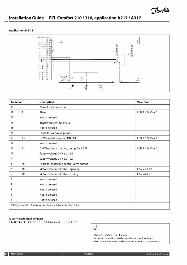
Application A317.1
ECL 310 / 24 V a.c.
Dan
foss
87H
2088
.10
Terminal Description Max. load
19 Phase for alarm output
18 A1 Alarm 4 (2) A / 24 V a.c.*
17 Not to be used
16 Interconnection for phase
15 Not to be used
14 Phase for control of pumps
13 K3 DHW circulation pump ON / OFF 4 (2) A / 24 V a.c.*
12 Not to be used
11 K1 DHW heating / charging pump ON / OFF 4 (2) A / 24 V a.c.*
10 Supply voltage 24 V a.c. - (N)
9 Supply voltage 24 V a.c. - (L)
8 M1 Phase for motorized control valve output
7 M1 Motorized control valve - opening 1 A / 24 V a.c.
6 M1 Motorized control valve - closing 1 A / 24 V a.c.
5 Not to be used
4 Not to be used
3 Not to be used
2 Not to be used
1 Not to be used
* Relay contacts: 4 A for ohmic load, 2 A for inductive load
Factory established jumpers:5 to 8, 9 to 14, 14 to 16, 16 to 19, L to 5 and L to 9, N to 10
Wire cross section: 0.5 - 1.5 mm²Incorrect connection can damage the electronic outputs.Max. 2 x 1.5 mm² wires can be inserted into each screw terminal.
40 DEN-SMT/DK VI.LG.U2.02 Danfoss District Energy

Installation Guide ECL Comfort 210 / 310, application A217 / A317
Do not connect 230 V a.c. powered components to a 24 V a.c. powersupplied controller directly. Use auxilliary relays (K) to separate 230V a.c. from 24 V a.c.
Danfoss District Energy VI.LG.U2.02 DEN-SMT/DK 41
Installation Guide ECL Comfort 210 / 310, application A217 / A317
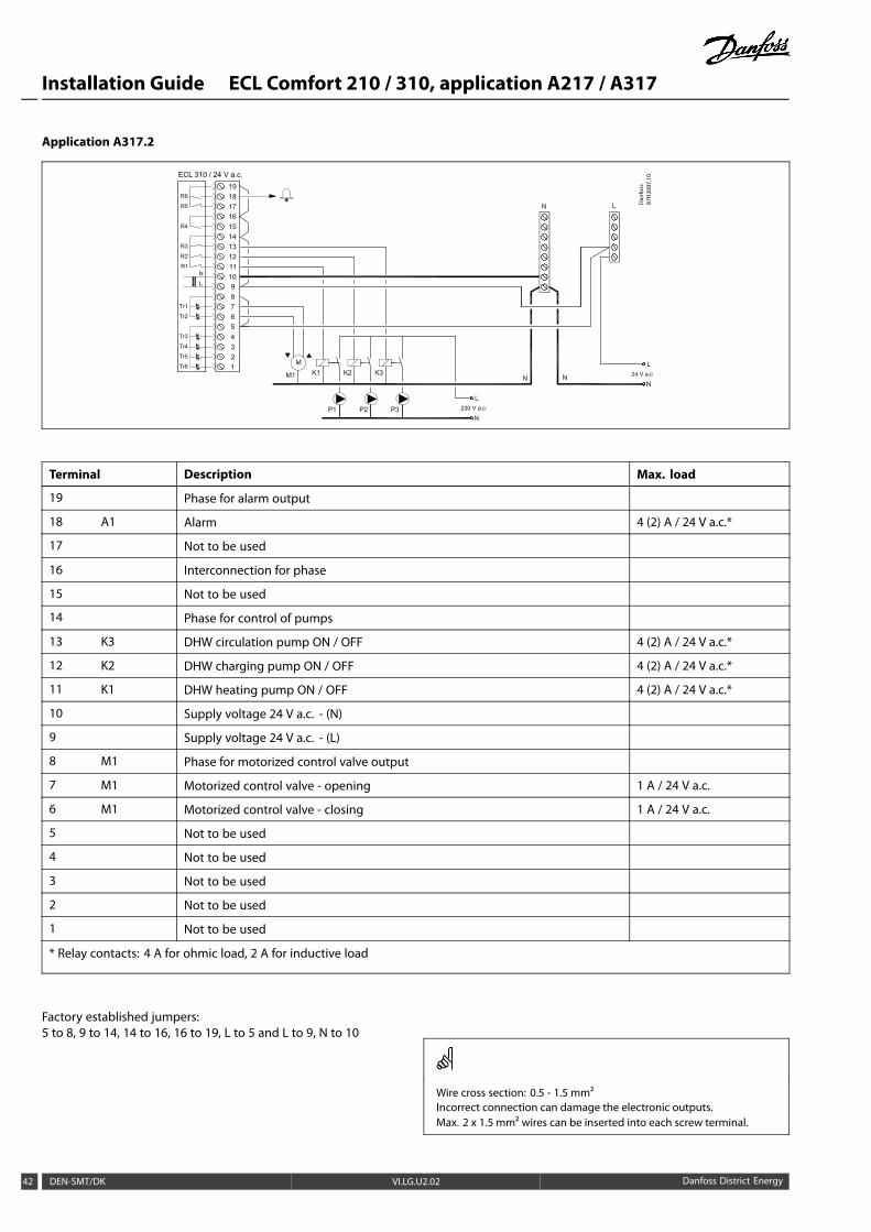
Application A317.2
ECL 310 / 24 V a.c.
Dan
foss
87H
2087
.10
Terminal Description Max. load
19 Phase for alarm output
18 A1 Alarm 4 (2) A / 24 V a.c.*
17 Not to be used
16 Interconnection for phase
15 Not to be used
14 Phase for control of pumps
13 K3 DHW circulation pump ON / OFF 4 (2) A / 24 V a.c.*
12 K2 DHW charging pump ON / OFF 4 (2) A / 24 V a.c.*
11 K1 DHW heating pump ON / OFF 4 (2) A / 24 V a.c.*
10 Supply voltage 24 V a.c. - (N)
9 Supply voltage 24 V a.c. - (L)
8 M1 Phase for motorized control valve output
7 M1 Motorized control valve - opening 1 A / 24 V a.c.
6 M1 Motorized control valve - closing 1 A / 24 V a.c.
5 Not to be used
4 Not to be used
3 Not to be used
2 Not to be used
1 Not to be used
* Relay contacts: 4 A for ohmic load, 2 A for inductive load
Factory established jumpers:5 to 8, 9 to 14, 14 to 16, 16 to 19, L to 5 and L to 9, N to 10
Wire cross section: 0.5 - 1.5 mm²Incorrect connection can damage the electronic outputs.Max. 2 x 1.5 mm² wires can be inserted into each screw terminal.
42 DEN-SMT/DK VI.LG.U2.02 Danfoss District Energy

Installation Guide ECL Comfort 210 / 310, application A217 / A317
Do not connect 230 V a.c. powered components to a 24 V a.c. powersupplied controller directly. Use auxilliary relays (K) to separate 230V a.c. from 24 V a.c.
Danfoss District Energy VI.LG.U2.02 DEN-SMT/DK 43
Installation Guide ECL Comfort 210 / 310, application A217 / A317
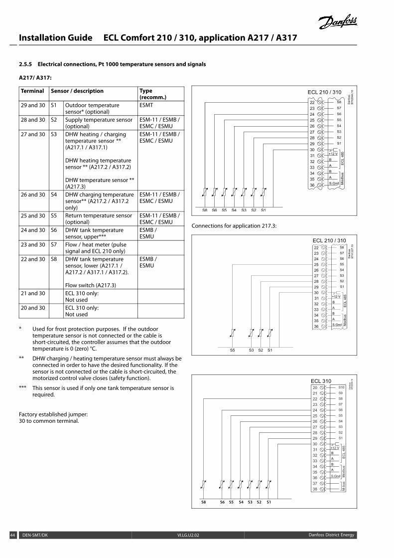
2.5.5 Electrical connections, Pt 1000 temperature sensors and signals
A217/ A317:
Terminal Sensor / description Type(recomm.)
29 and 30 S1 Outdoor temperaturesensor* (optional)
ESMT
28 and 30 S2 Supply temperature sensor(optional)
ESM-11 / ESMB /ESMC / ESMU
27 and 30 S3 DHW heating / chargingtemperature sensor **(A217.1 / A317.1)
DHW heating temperaturesensor ** (A217.2 / A317.2)
DHW temperature sensor **(A217.3)
ESM-11 / ESMB /ESMC / ESMU
26 and 30 S4 DHW charging temperaturesensor** (A217.2 / A317.2only)
ESM-11 / ESMB /ESMC / ESMU
25 and 30 S5 Return temperature sensor(optional)
ESM-11 / ESMB /ESMC / ESMU
24 and 30 S6 DHW tank temperaturesensor, upper***
ESMB /ESMU
23 and 30 S7 Flow / heat meter (pulsesignal and ECL 210 only)
22 and 30 S8 DHW tank temperaturesensor, lower (A217.1 /A217.2 / A317.1 / A317.2).
Flow switch (A217.3)
ESMB /ESMU
21 and 30 ECL 310 only:Not used
20 and 30 ECL 310 only:Not used
* Used for frost protection purposes. If the outdoortemperature sensor is not connected or the cable isshort-circuited, the controller assumes that the outdoortemperature is 0 (zero) °C.
** DHW charging / heating temperature sensor must always beconnected in order to have the desired functionality. If thesensor is not connected or the cable is short-circuited, themotorized control valve closes (safety function).
*** This sensor is used if only one tank temperature sensor isrequired.
Factory established jumper:30 to common terminal.
A
A
B
B
ECL 210 / 310
Dan
foss
87H
2044
.10
Connections for application 217.3:
87H
2065
.10
Dan
foss
A
A
B
B
S8 S6 S5 S4 S3 S2 S1
ECL 310
44 DEN-SMT/DK VI.LG.U2.02 Danfoss District Energy
Installation Guide ECL Comfort 210 / 310, application A217 / A317
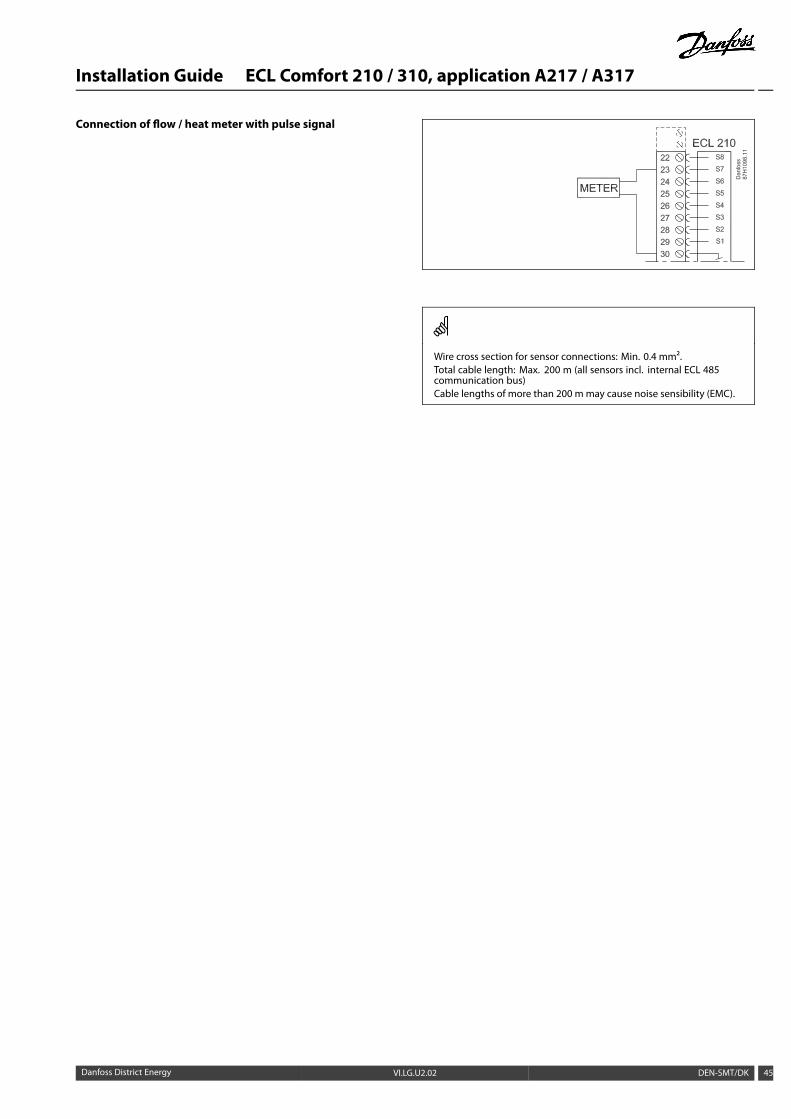
Connection of flow / heat meter with pulse signal
Wire cross section for sensor connections: Min. 0.4 mm².Total cable length: Max. 200 m (all sensors incl. internal ECL 485communication bus)Cable lengths of more than 200 m may cause noise sensibility (EMC).
Danfoss District Energy VI.LG.U2.02 DEN-SMT/DK 45

Installation Guide ECL Comfort 210 / 310, application A217 / A317
Connection of flow switch, S8 (A217.3)
46 DEN-SMT/DK VI.LG.U2.02 Danfoss District Energy
Installation Guide ECL Comfort 210 / 310, application A217 / A317
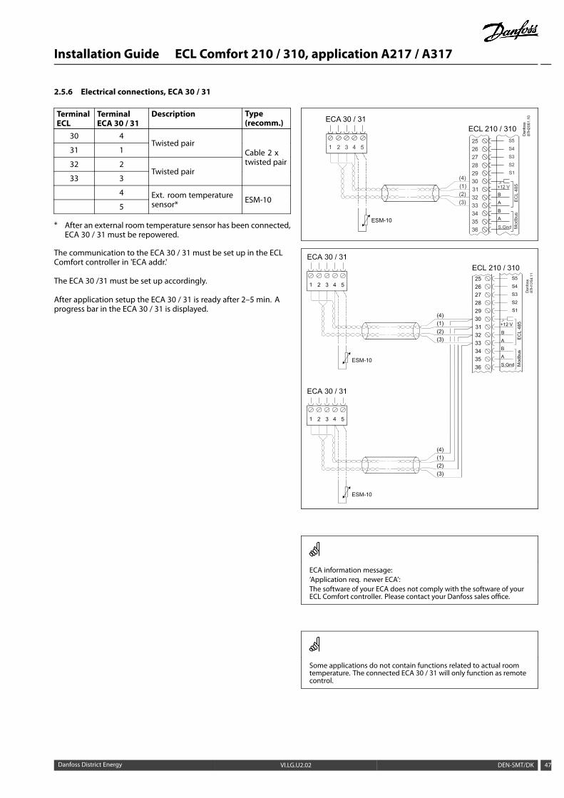
2.5.6 Electrical connections, ECA 30 / 31
TerminalECL
TerminalECA 30 / 31
Description Type(recomm.)
30 4
31 1Twisted pair
32 2
33 3Twisted pair
Cable 2 xtwisted pair
4
5Ext. room temperaturesensor* ESM-10
* After an external room temperature sensor has been connected,ECA 30 / 31 must be repowered.
The communication to the ECA 30 / 31 must be set up in the ECLComfort controller in 'ECA addr.'
The ECA 30 /31 must be set up accordingly.
After application setup the ECA 30 / 31 is ready after 2–5 min. Aprogress bar in the ECA 30 / 31 is displayed.
ECL 210 / 310ECA 30 / 31
A
A
B
B
Dan
foss
87H
2051
.10
ESM-10
ECA information message:‘Application req. newer ECA’:The software of your ECA does not comply with the software of yourECL Comfort controller. Please contact your Danfoss sales office.
Some applications do not contain functions related to actual roomtemperature. The connected ECA 30 / 31 will only function as remotecontrol.
Danfoss District Energy VI.LG.U2.02 DEN-SMT/DK 47
Installation Guide ECL Comfort 210 / 310, application A217 / A317
Total cable length: Max. 200 m (all sensors incl. internal ECL 485communication bus).Cable lengths of more than 200 m may cause noise sensibility (EMC).
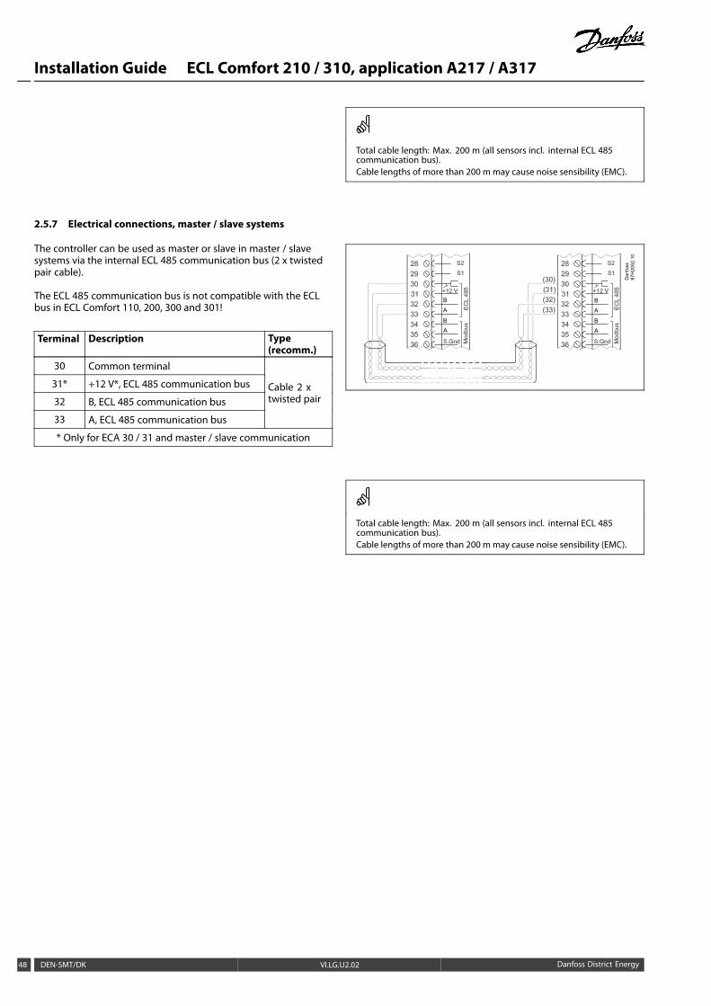
2.5.7 Electrical connections, master / slave systems
The controller can be used as master or slave in master / slavesystems via the internal ECL 485 communication bus (2 x twistedpair cable).
The ECL 485 communication bus is not compatible with the ECLbus in ECL Comfort 110, 200, 300 and 301!
Terminal Description Type(recomm.)
30 Common terminal
31* +12 V*, ECL 485 communication bus
32 B, ECL 485 communication bus
33 A, ECL 485 communication bus
Cable 2 xtwisted pair
* Only for ECA 30 / 31 and master / slave communication
Dan
foss
87H
2052
.10
A
A
B
B
A
A
B
B
Total cable length: Max. 200 m (all sensors incl. internal ECL 485communication bus).Cable lengths of more than 200 m may cause noise sensibility (EMC).
48 DEN-SMT/DK VI.LG.U2.02 Danfoss District Energy
Installation Guide ECL Comfort 210 / 310, application A217 / A317
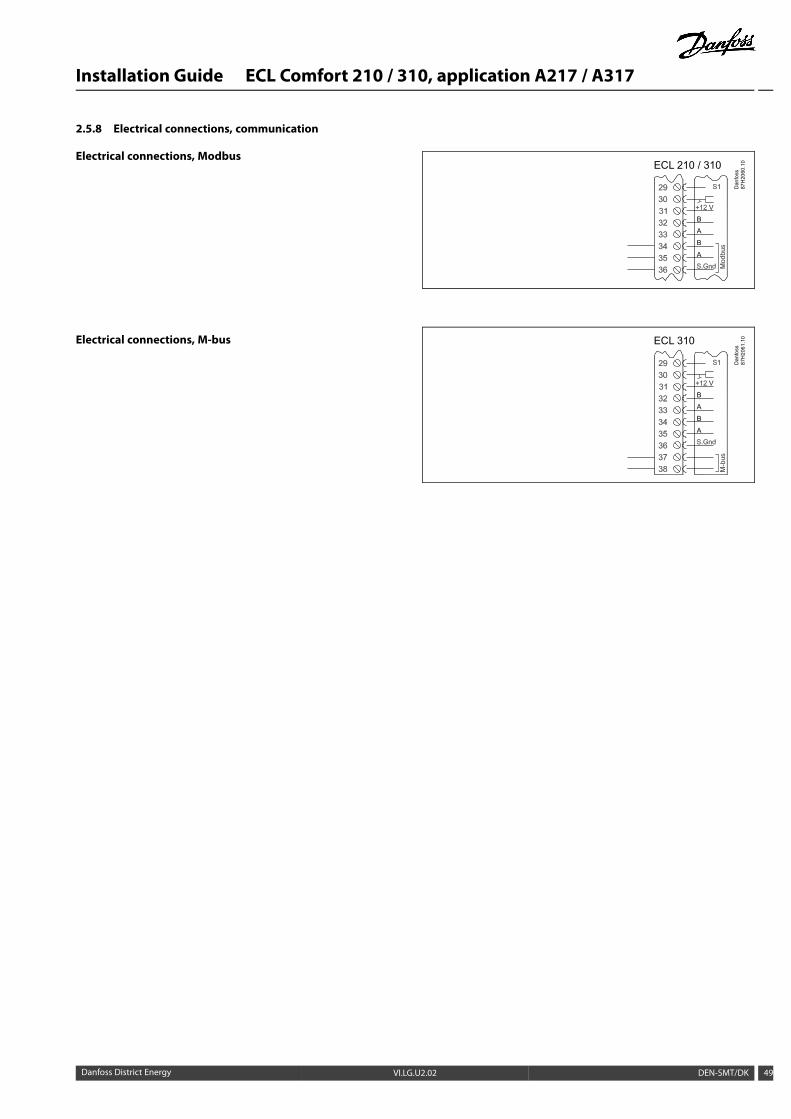
2.5.8 Electrical connections, communication
Electrical connections, Modbus
Electrical connections, M-bus
ECL 210 / 310
Dan
foss
87H
2060
.10
A
A
B
B
ECL 310
Dan
foss
87H
2061
.10
A
A
B
B
Danfoss District Energy VI.LG.U2.02 DEN-SMT/DK 49
Installation Guide ECL Comfort 210 / 310, application A217 / A317
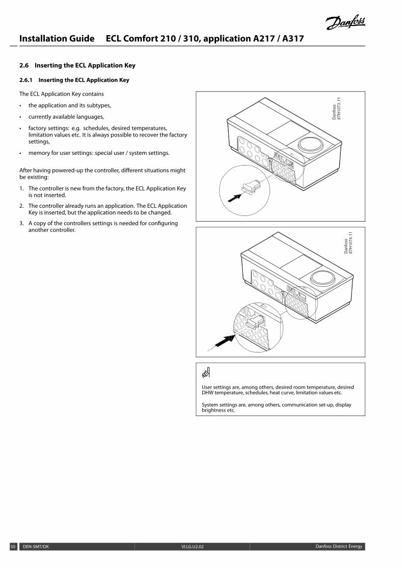
2.6 Inserting the ECL Application Key
2.6.1 Inserting the ECL Application Key
The ECL Application Key contains
• the application and its subtypes,
• currently available languages,
• factory settings: e.g. schedules, desired temperatures,limitation values etc. It is always possible to recover the factorysettings,
• memory for user settings: special user / system settings.
After having powered-up the controller, different situations mightbe existing:
1. The controller is new from the factory, the ECL Application Keyis not inserted.
2. The controller already runs an application. The ECL ApplicationKey is inserted, but the application needs to be changed.
3. A copy of the controllers settings is needed for configuringanother controller.
User settings are, among others, desired room temperature, desiredDHW temperature, schedules, heat curve, limitation values etc.
System settings are, among others, communication set-up, displaybrightness etc.
50 DEN-SMT/DK VI.LG.U2.02 Danfoss District Energy
Installation Guide ECL Comfort 210 / 310, application A217 / A317
Automatic update of controller software:The software of the controller is updated automatically when the keyis inserted (as of controller version 1.11). The following animation willbe shown when the software is being updated:
Progress bar
During update:- Do not remove the KEY- Do not disconnect the power
Danfoss District Energy VI.LG.U2.02 DEN-SMT/DK 51
Installation Guide ECL Comfort 210 / 310, application A217 / A317
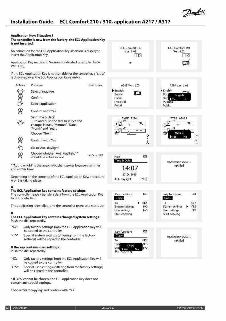
Application Key: Situation 1The controller is new from the factory, the ECL Application Keyis not inserted.
An animation for the ECL Application Key insertion is displayed.Insert the Application Key .
Application Key name and Version is indicated (example: A266Ver. 1.03).
If the ECL Application Key is not suitable for the controller, a "cross"is displayed over the ECL Application Key-symbol.
Action: Purpose: Examples:
Select language
Confirm
Select application
Confirm with ‘Yes’
Set 'Time & Date'Turn and push the dial to select andchange 'Hours', 'Minutes', 'Date','Month' and 'Year'.Choose ''Next'
Confirm with ‘Yes’
Go to ‘Aut. daylight’
Choose whether ‘Aut. daylight´ *should be active or not YES or NO
* ‘Aut. daylight’ is the automatic changeover between summerand winter time.
Depending on the contents of the ECL Application Key, procedureA or B is taking place:
AThe ECL Application key contains factory settings:The controller reads / transfers data from the ECL Application Keyto ECL controller.
The application is installed, and the controller resets and starts up.
BThe ECL Application key contains changed system settings:Push the dial repeatedly.
’NO’: Only factory settings from the ECL Application Key willbe copied to the controller.
’YES*: Special system settings (differing from the factorysettings) will be copied to the controller.
If the key contains user settings:Push the dial repeatedly.
‘NO: Only factory settings from the ECL Application Key willbe copied to the controller.
‘YES*: Special user settings (differing from the factory settings)will be copied to the controller.
* If ‘YES’ cannot be chosen, the ECL Application Key does notcontain any special settings.
Choose ‘Start copying’ and confirm with 'Yes'.
52 DEN-SMT/DK VI.LG.U2.02 Danfoss District Energy
Installation Guide ECL Comfort 210 / 310, application A217 / A317
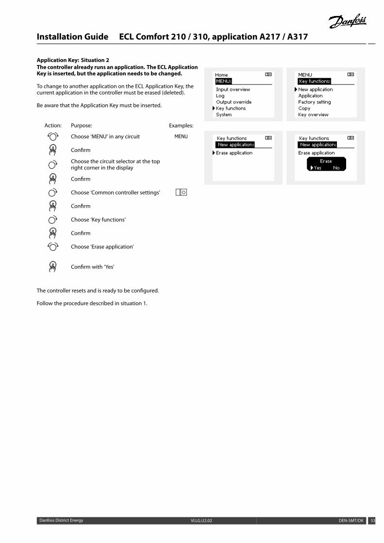
Application Key: Situation 2The controller already runs an application. The ECL ApplicationKey is inserted, but the application needs to be changed.
To change to another application on the ECL Application Key, thecurrent application in the controller must be erased (deleted).
Be aware that the Application Key must be inserted.
Action: Purpose: Examples:
Choose ‘MENU’ in any circuit
Confirm
Choose the circuit selector at the topright corner in the display
Confirm
Choose ‘Common controller settings’
Confirm
Choose ‘Key functions’
Confirm
Choose ‘Erase application’
Confirm with ‘Yes’
The controller resets and is ready to be configured.
Follow the procedure described in situation 1.
Danfoss District Energy VI.LG.U2.02 DEN-SMT/DK 53
Installation Guide ECL Comfort 210 / 310, application A217 / A317
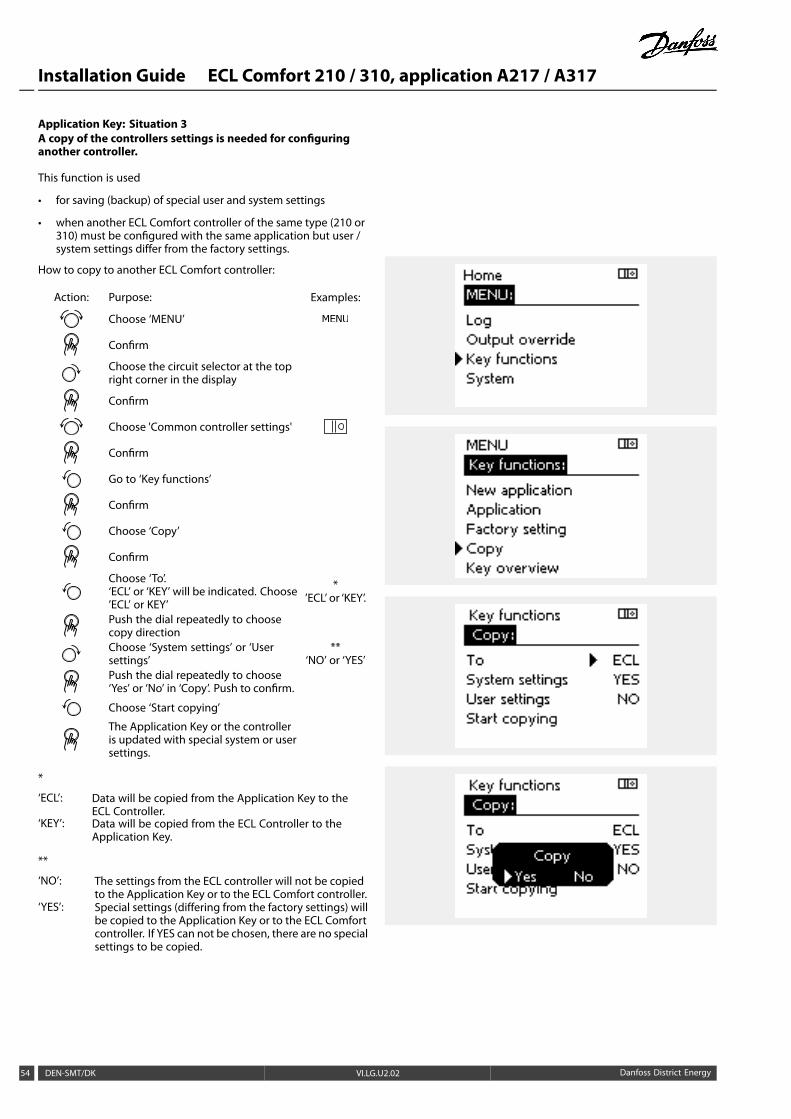
Application Key: Situation 3A copy of the controllers settings is needed for configuringanother controller.
This function is used
• for saving (backup) of special user and system settings
• when another ECL Comfort controller of the same type (210 or310) must be configured with the same application but user /system settings differ from the factory settings.
How to copy to another ECL Comfort controller:
Action: Purpose: Examples:
Choose ‘MENU’
Confirm
Choose the circuit selector at the topright corner in the display
Confirm
Choose 'Common controller settings'
Confirm
Go to ‘Key functions’
Confirm
Choose ‘Copy’
Confirm
Choose ‘To’.‘ECL’ or ‘KEY’ will be indicated. Choose’ECL’ or KEY’
*’ECL’ or ‘KEY’.
Push the dial repeatedly to choosecopy directionChoose ‘System settings’ or ‘Usersettings’
**‘NO’ or ‘YES’
Push the dial repeatedly to choose‘Yes’ or ‘No’ in ‘Copy’. Push to confirm.
Choose ‘Start copying’
The Application Key or the controlleris updated with special system or usersettings.
*
‘ECL’: Data will be copied from the Application Key to theECL Controller.
‘KEY’: Data will be copied from the ECL Controller to theApplication Key.
**
‘NO’: The settings from the ECL controller will not be copiedto the Application Key or to the ECL Comfort controller.
‘YES’: Special settings (differing from the factory settings) willbe copied to the Application Key or to the ECL Comfortcontroller. If YES can not be chosen, there are no specialsettings to be copied.
54 DEN-SMT/DK VI.LG.U2.02 Danfoss District Energy
Installation Guide ECL Comfort 210 / 310, application A217 / A317
2.6.2 ECL Application Key, copying data
General principlesWhen the controller is connected and operating, you can checkand adjust all or some of the basic settings. The new settings canbe stored on the Key.
How to update the ECL Application Key after settings havebeen changed?All new settings can be stored on the ECL Application Key.
How to store factory setting in the controller from theApplication Key?Please read the paragraph concerning Application Key, Situation1: The controller is new from the factory, the ECL Application Keyis not inserted.
How to store personal settings from the controller to the Key?Please read the paragraph concerning Application Key, Situation 3:A copy of the controllers settings is needed for configuring anothercontroller
As a main rule, the ECL Application Key should always remain inthe controller. If the Key is removed, it is not possible to changesettings.
Factory settings can always be restored.
Make a note of new settings in the 'Settings overview' table.
Do not remove the ECL Application Key while copying. The data onthe ECL Application Key can be damaged!
It is possible to copy settings from one ECL Comfort controller toanother controller provided that the two controllers are from the sameseries (210 or 310).
Danfoss District Energy VI.LG.U2.02 DEN-SMT/DK 55
Installation Guide ECL Comfort 210 / 310, application A217 / A317
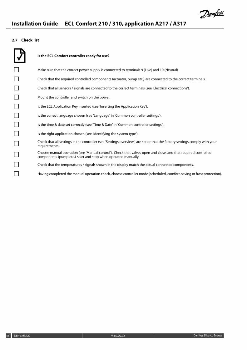
2.7 Check list
Is the ECL Comfort controller ready for use?
Make sure that the correct power supply is connected to terminals 9 (Live) and 10 (Neutral).
Check that the required controlled components (actuator, pump etc.) are connected to the correct terminals.
Check that all sensors / signals are connected to the correct terminals (see 'Electrical connections').
Mount the controller and switch on the power.
Is the ECL Application Key inserted (see 'Inserting the Application Key').
Is the correct language chosen (see 'Language' in 'Common controller settings').
Is the time & date set correctly (see 'Time & Date' in 'Common controller settings').
Is the right application chosen (see 'Identifying the system type').
Check that all settings in the controller (see 'Settings overview') are set or that the factory settings comply with yourrequirements.
Choose manual operation (see 'Manual control'). Check that valves open and close, and that required controlledcomponents (pump etc.) start and stop when operated manually.
Check that the temperatures / signals shown in the display match the actual connected components.
Having completed themanual operation check, choose controller mode (scheduled, comfort, saving or frost protection).
56 DEN-SMT/DK VI.LG.U2.02 Danfoss District Energy

Installation Guide ECL Comfort 210 / 310, application A217 / A317
2.8 Navigation, ECL Application Key A217 / A317
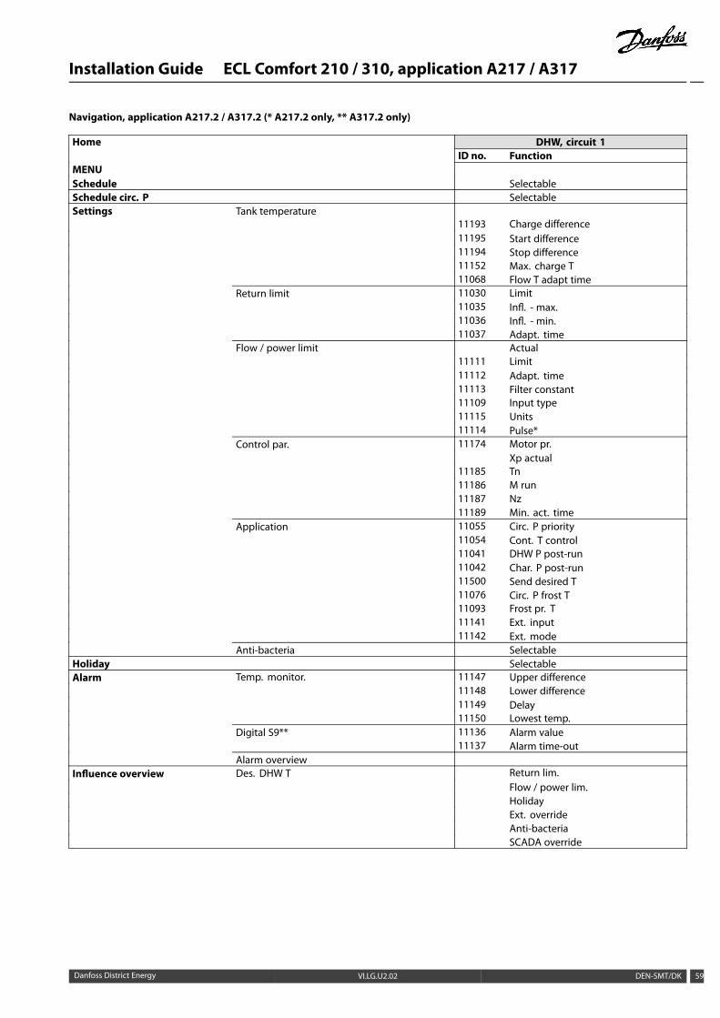
Navigation, application A217.1 / A317.1 (* A217.1 only, ** A317.1 only)
Home DHW, circuit 1ID no. Function
MENUSchedule SelectableSchedule circ. P SelectableSettings Tank temperature 11193 Charge difference
11195 Start difference11194 Stop difference11152 Max. charge T
Return limit 11030 Limit11035 Infl. - max.11036 Infl. - min.11037 Adapt. time
Flow / power limit Actual11111 Limit11112 Adapt. time11113 Filter constant11109 Input type11115 Units11114 Pulse*
Control par. 11174 Motor pr.Xp actual
11185 Tn11186 M run11187 Nz11189 Min. act. time
Application 11055 Circ. P priority11054 Cont. T control11041 DHW P post-run11500 Send desired T11076 Circ. P frost T11093 Frost pr. T11141 Ext. input11142 Ext. mode
Anti-bacteria SelectableHoliday SelectableAlarm Temp. monitor. 11147 Upper difference
11148 Lower difference11149 Delay11150 Lowest temp.
Digital S9** 11636 Alarm value11637 Alarm time-out
Alarm overviewInfluence overview Des. DHW T Return lim.
Flow / power lim.HolidayExt. overrideAnti-bacteriaSCADA override
Danfoss District Energy VI.LG.U2.02 DEN-SMT/DK 57
Installation Guide ECL Comfort 210 / 310, application A217 / A317
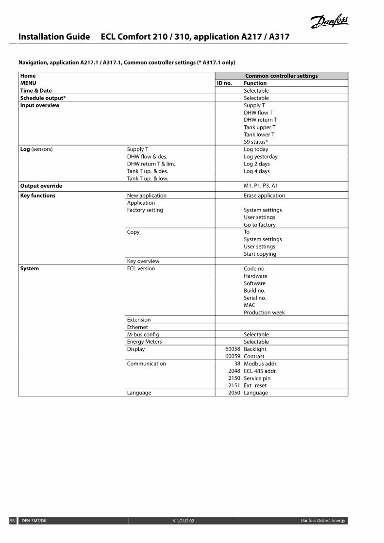
Navigation, application A217.1 / A317.1, Common controller settings (* A317.1 only)
Home Common controller settingsMENU ID no. FunctionTime & Date SelectableSchedule output* SelectableInput overview Supply T
DHW flow TDHW return TTank upper TTank lower TS9 status*
Log (sensors) Supply T Log todayDHW flow & des. Log yesterdayDHW return T & lim. Log 2 daysTank T up. & des. Log 4 daysTank T up. & low.
Output override M1, P1, P3, A1
Key functions New application Erase applicationApplicationFactory setting System settings
User settingsGo to factory
Copy ToSystem settingsUser settingsStart copying
Key overviewSystem ECL version Code no.
HardwareSoftwareBuild no.Serial no.MACProduction week
ExtensionEthernetM-bus config SelectableEnergy Meters SelectableDisplay 60058 Backlight
60059 ContrastCommunication 38 Modbus addr.
2048 ECL 485 addr.2150 Service pin2151 Ext. reset
Language 2050 Language
58 DEN-SMT/DK VI.LG.U2.02 Danfoss District Energy
Installation Guide ECL Comfort 210 / 310, application A217 / A317
Navigation, application A217.2 / A317.2 (* A217.2 only, ** A317.2 only)
Home DHW, circuit 1ID no. Function
MENUSchedule SelectableSchedule circ. P SelectableSettings Tank temperature
11193 Charge difference11195 Start difference11194 Stop difference11152 Max. charge T11068 Flow T adapt time
Return limit 11030 Limit11035 Infl. - max.11036 Infl. - min.11037 Adapt. time
Flow / power limit Actual11111 Limit11112 Adapt. time11113 Filter constant11109 Input type11115 Units11114 Pulse*
Control par. 11174 Motor pr.Xp actual
11185 Tn11186 M run11187 Nz11189 Min. act. time
Application 11055 Circ. P priority11054 Cont. T control11041 DHW P post-run11042 Char. P post-run11500 Send desired T11076 Circ. P frost T11093 Frost pr. T11141 Ext. input11142 Ext. mode
Anti-bacteria SelectableHoliday SelectableAlarm Temp. monitor. 11147 Upper difference
11148 Lower difference11149 Delay11150 Lowest temp.
Digital S9** 11136 Alarm value11137 Alarm time-out
Alarm overviewInfluence overview Des. DHW T Return lim.
Flow / power lim.HolidayExt. overrideAnti-bacteriaSCADA override
Danfoss District Energy VI.LG.U2.02 DEN-SMT/DK 59
Installation Guide ECL Comfort 210 / 310, application A217 / A317
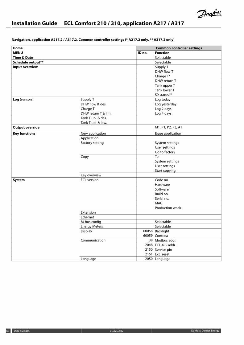
Navigation, application A217.2 / A317.2, Common controller settings (* A217.2 only, ** A317.2 only)
Home Common controller settingsMENU ID no. FunctionTime & Date SelectableSchedule output** SelectableInput overview Supply T
DHW flow TCharge T*DHW return TTank upper TTank lower TS9 status**
Log (sensors) Supply T Log todayDHW flow & des. Log yesterdayCharge T Log 2 daysDHW return T & lim. Log 4 daysTank T up. & des.Tank T up. & low.
Output override M1, P1, P2, P3, A1
Key functions New application Erase applicationApplicationFactory setting System settings
User settingsGo to factory
Copy ToSystem settingsUser settingsStart copying
Key overviewSystem ECL version Code no.
HardwareSoftwareBuild no.Serial no.MACProduction week
ExtensionEthernetM-bus config SelectableEnergy Meters SelectableDisplay 60058 Backlight
60059 ContrastCommunication 38 Modbus addr.
2048 ECL 485 addr.2150 Service pin2151 Ext. reset
Language 2050 Language
60 DEN-SMT/DK VI.LG.U2.02 Danfoss District Energy
Installation Guide ECL Comfort 210 / 310, application A217 / A317
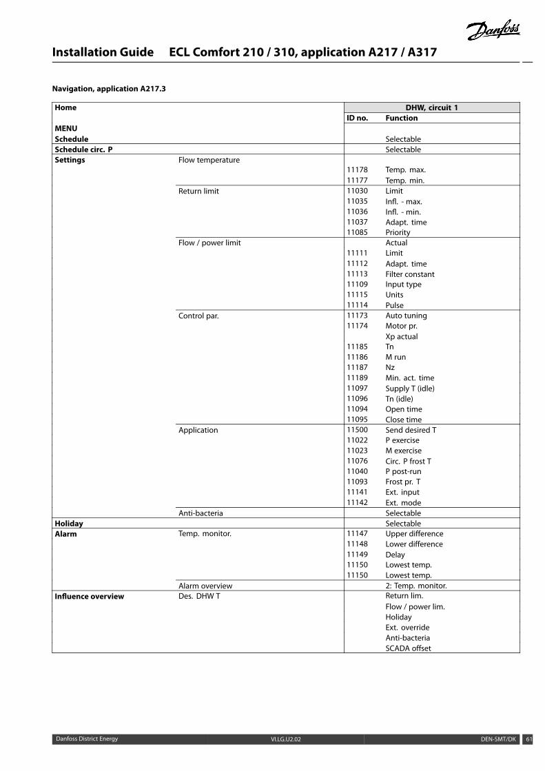
Navigation, application A217.3
Home DHW, circuit 1ID no. Function
MENUSchedule SelectableSchedule circ. P SelectableSettings Flow temperature
11178 Temp. max.11177 Temp. min.
Return limit 11030 Limit11035 Infl. - max.11036 Infl. - min.11037 Adapt. time11085 Priority
Flow / power limit Actual11111 Limit11112 Adapt. time11113 Filter constant11109 Input type11115 Units11114 Pulse
Control par. 11173 Auto tuning11174 Motor pr.
Xp actual11185 Tn11186 M run11187 Nz11189 Min. act. time11097 Supply T (idle)11096 Tn (idle)11094 Open time11095 Close time
Application 11500 Send desired T11022 P exercise11023 M exercise11076 Circ. P frost T11040 P post-run11093 Frost pr. T11141 Ext. input11142 Ext. mode
Anti-bacteria SelectableHoliday SelectableAlarm Temp. monitor. 11147 Upper difference
11148 Lower difference11149 Delay11150 Lowest temp.11150 Lowest temp.
Alarm overview 2: Temp. monitor.Influence overview Des. DHW T Return lim.
Flow / power lim.HolidayExt. overrideAnti-bacteriaSCADA offset
Danfoss District Energy VI.LG.U2.02 DEN-SMT/DK 61
Installation Guide ECL Comfort 210 / 310, application A217 / A317
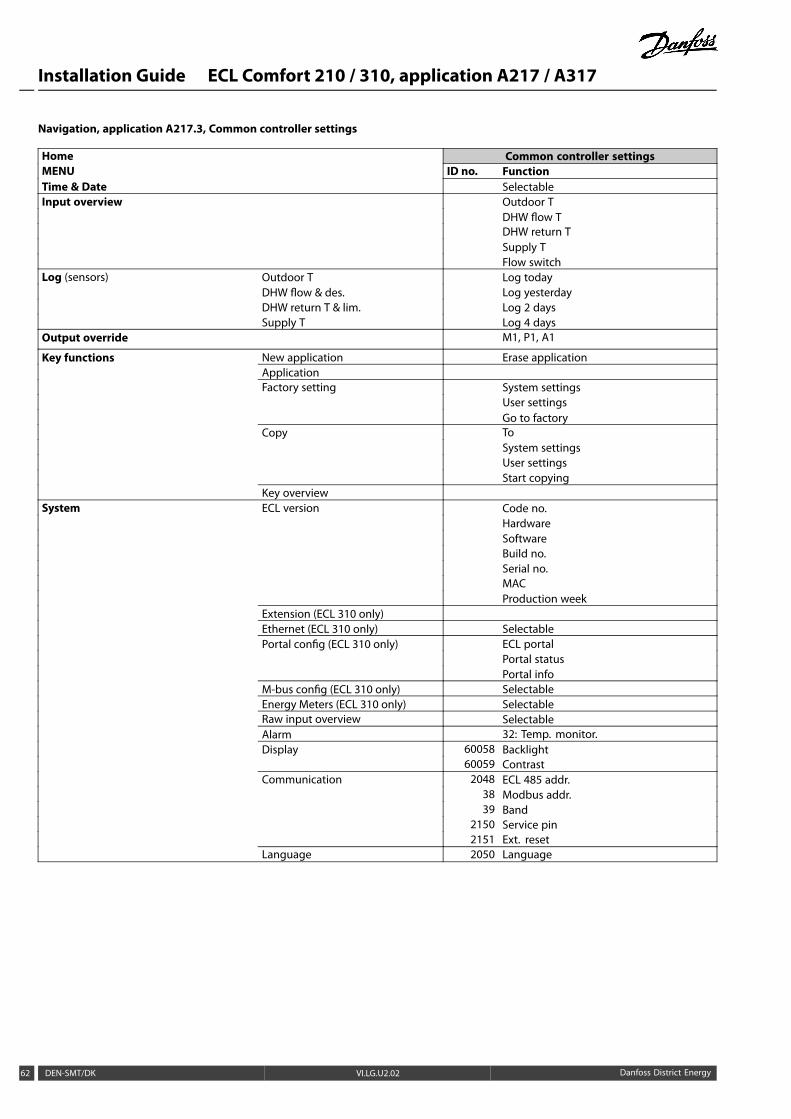
Navigation, application A217.3, Common controller settings
Home Common controller settingsMENU ID no. FunctionTime & Date SelectableInput overview Outdoor T
DHW flow TDHW return TSupply TFlow switch
Log (sensors) Outdoor T Log todayDHW flow & des. Log yesterdayDHW return T & lim. Log 2 daysSupply T Log 4 days
Output override M1, P1, A1
Key functions New application Erase applicationApplicationFactory setting System settings
User settingsGo to factory
Copy ToSystem settingsUser settingsStart copying
Key overviewSystem ECL version Code no.
HardwareSoftwareBuild no.Serial no.MACProduction week
Extension (ECL 310 only)Ethernet (ECL 310 only) SelectablePortal config (ECL 310 only) ECL portal
Portal statusPortal info
M-bus config (ECL 310 only) SelectableEnergy Meters (ECL 310 only) SelectableRaw input overview SelectableAlarm 32: Temp. monitor.Display 60058 Backlight
60059 ContrastCommunication 2048 ECL 485 addr.
38 Modbus addr.39 Band
2150 Service pin2151 Ext. reset
Language 2050 Language
62 DEN-SMT/DK VI.LG.U2.02 Danfoss District Energy
Installation Guide ECL Comfort 210 / 310, application A217 / A317
3.0 Daily use
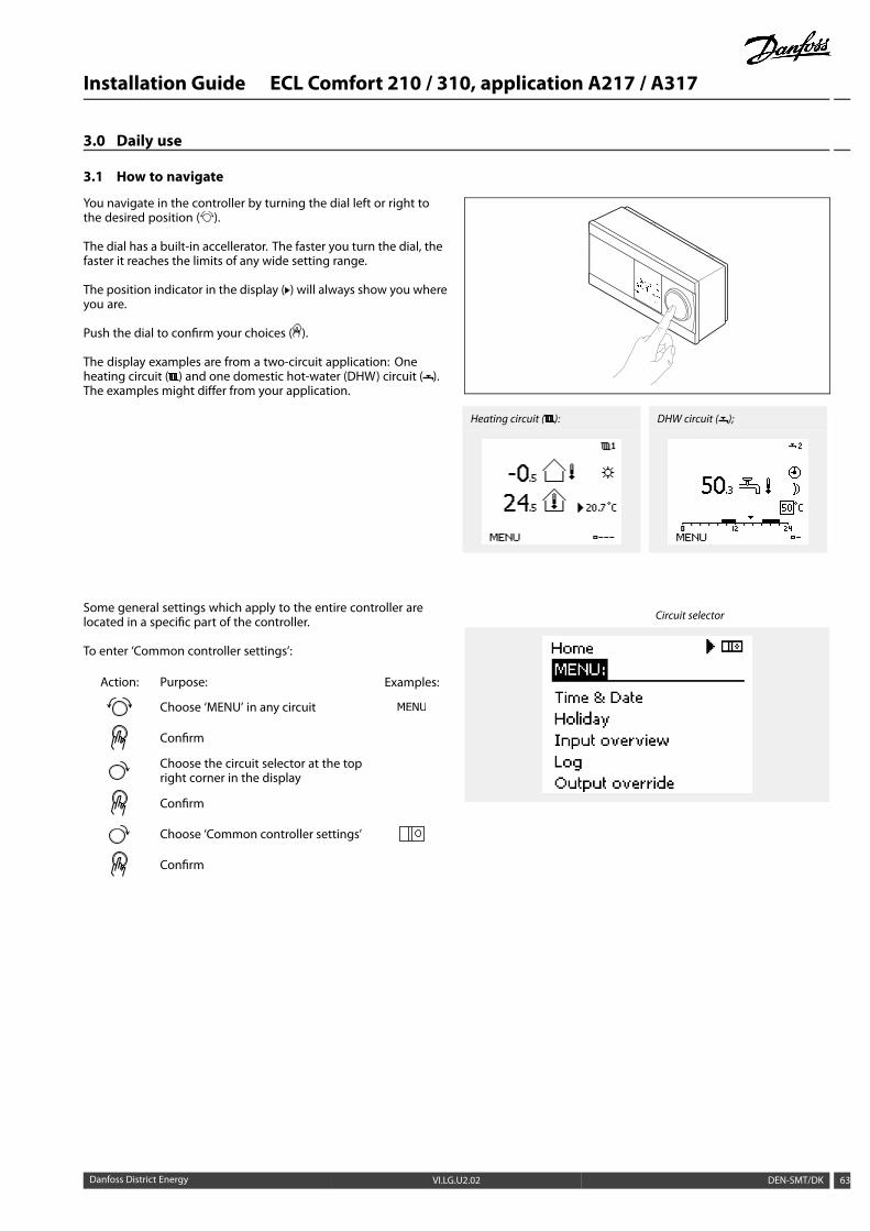
3.1 How to navigate
You navigate in the controller by turning the dial left or right tothe desired position ( ).
The dial has a built-in accellerator. The faster you turn the dial, thefaster it reaches the limits of any wide setting range.
The position indicator in the display ( ) will always show you whereyou are.
Push the dial to confirm your choices ( ).
The display examples are from a two-circuit application: Oneheating circuit ( ) and one domestic hot-water (DHW) circuit ( ).The examples might differ from your application.
Heating circuit ( ): DHW circuit ( );
Some general settings which apply to the entire controller arelocated in a specific part of the controller.
To enter ‘Common controller settings’:
Action: Purpose: Examples:
Choose ‘MENU’ in any circuit
Confirm
Choose the circuit selector at the topright corner in the display
Confirm
Choose ‘Common controller settings’
Confirm
Circuit selector
Danfoss District Energy VI.LG.U2.02 DEN-SMT/DK 63
Installation Guide ECL Comfort 210 / 310, application A217 / A317
3.2 Understanding the controller display
Choosing a favorite displayYour favorite display is the display you have chosen as the defaultdisplay. The favorite display will give you a quick overview of thetemperatures or units that you want to monitor in general.
If the dial has not been activated for 20 min., the controller willrevert to the overview display you have chosen as favorite.
To shift between displays: Turn the dial until you reach the displayselector ( ) at the bottom right side of the display. Push the dial andturn to choose your favorite overview display. Push the dial again.
If the temperature value is displayed as
"- -" the sensor in question is not connected.
"- - -" the sensor connection is short-circuited.
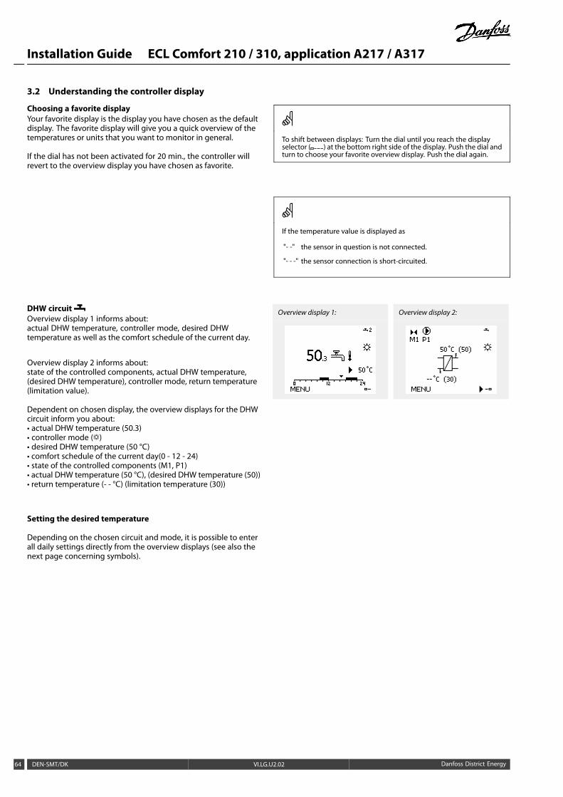
DHW circuitOverview display 1 informs about:actual DHW temperature, controller mode, desired DHWtemperature as well as the comfort schedule of the current day.
Overview display 2 informs about:state of the controlled components, actual DHW temperature,(desired DHW temperature), controller mode, return temperature(limitation value).
Dependent on chosen display, the overview displays for the DHWcircuit inform you about:• actual DHW temperature (50.3)• controller mode ( )• desired DHW temperature (50 °C)• comfort schedule of the current day(0 - 12 - 24)• state of the controlled components (M1, P1)• actual DHW temperature (50 °C), (desired DHW temperature (50))• return temperature (- - °C) (limitation temperature (30))
Overview display 1: Overview display 2:
Setting the desired temperature
Depending on the chosen circuit and mode, it is possible to enterall daily settings directly from the overview displays (see also thenext page concerning symbols).
64 DEN-SMT/DK VI.LG.U2.02 Danfoss District Energy
Installation Guide ECL Comfort 210 / 310, application A217 / A317
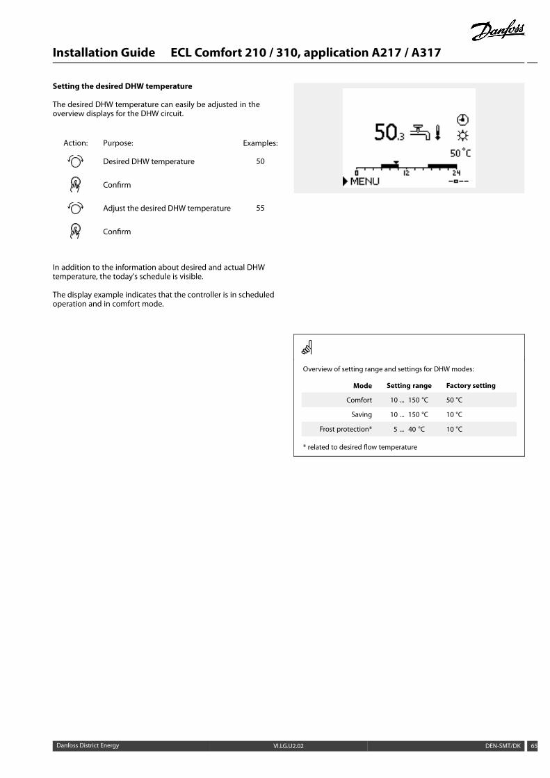
Setting the desired DHW temperature
The desired DHW temperature can easily be adjusted in theoverview displays for the DHW circuit.
Action: Purpose: Examples:
Desired DHW temperature 50
Confirm
Adjust the desired DHW temperature 55
Confirm
In addition to the information about desired and actual DHWtemperature, the today's schedule is visible.
The display example indicates that the controller is in scheduledoperation and in comfort mode.
Overview of setting range and settings for DHW modes:
Mode Setting range Factory setting
Comfort 10 ... 150 °C 50 °C
Saving 10 ... 150 °C 10 °C
Frost protection* 5 ... 40 °C 10 °C
* related to desired flow temperature
Danfoss District Energy VI.LG.U2.02 DEN-SMT/DK 65
Installation Guide ECL Comfort 210 / 310, application A217 / A317
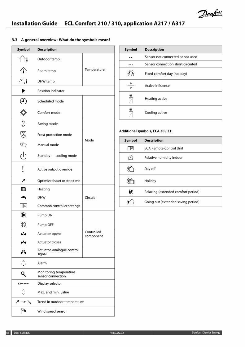
3.3 A general overview: What do the symbols mean?
Symbol Description
Outdoor temp.
Room temp.
DHW temp.
Temperature
Position indicator
Scheduled mode
Comfort mode
Saving mode
Frost protection mode
Manual mode
Standby — cooling mode
! Active output override
Optimized start or stop time
Mode
Heating
DHW
Common controller settings
Circuit
Pump ON
Pump OFF
Actuator opens
Actuator closes
42 Actuator, analogue controlsignal
Controlledcomponent
Alarm
Monitoring temperaturesensor connection
Display selector
Max. and min. value
Trend in outdoor temperature
Wind speed sensor
Symbol Description
Sensor not connected or not used
Sensor connection short-circuited
7-23 Fixed comfort day (holiday)
Active influence
Heating active
Cooling active
Additional symbols, ECA 30 / 31:
Symbol Description
ECA Remote Control Unit
Relative humidity indoor
Day off
Holiday
Relaxing (extended comfort period)
Going out (extended saving period)
66 DEN-SMT/DK VI.LG.U2.02 Danfoss District Energy
Installation Guide ECL Comfort 210 / 310, application A217 / A317
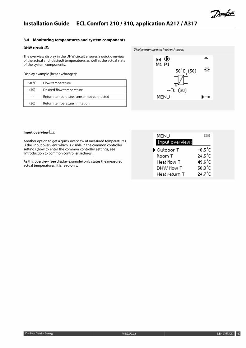
3.4 Monitoring temperatures and system components
DHW circuit
The overview display in the DHW circuit ensures a quick overviewof the actual and (desired) temperatures as well as the actual stateof the system components.
Display example (heat exchanger):
50 °C Flow temperature
(50) Desired flow temperature
- - Return temperature: sensor not connected
(30) Return temperature limitation
Display example with heat exchanger:
Input overview
Another option to get a quick overview of measured temperaturesis the 'Input overview' which is visible in the common controllersettings (how to enter the common controller settings, see‘Introduction to common controller settings’.)
As this overview (see display example) only states the measuredactual temperatures, it is read-only.
Danfoss District Energy VI.LG.U2.02 DEN-SMT/DK 67
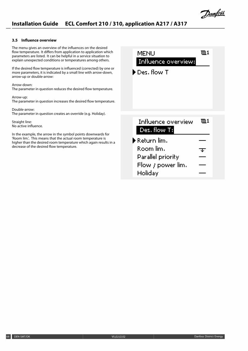
Installation Guide ECL Comfort 210 / 310, application A217 / A317
3.5 Influence overview
The menu gives an overview of the influences on the desiredflow temperature. It differs from application to application whichparameters are listed. It can be helpful in a service situation toexplain unexpected conditions or temperatures among others.
If the desired flow temperature is influenced (corrected) by one ormore parameters, it is indicated by a small line with arrow-down,arrow-up or double-arrow:
Arrow-down:The parameter in question reduces the desired flow temperature.
Arrow-up:The parameter in question increases the desired flow temperature.
Double-arrow:The parameter in question creates an override (e.g. Holiday).
Straight line:No active influence.
In the example, the arrow in the symbol points downwards for'Room lim.'. This means that the actual room temperature ishigher than the desired room temperature which again results in adecrease of the desired flow temperature.
68 DEN-SMT/DK VI.LG.U2.02 Danfoss District Energy
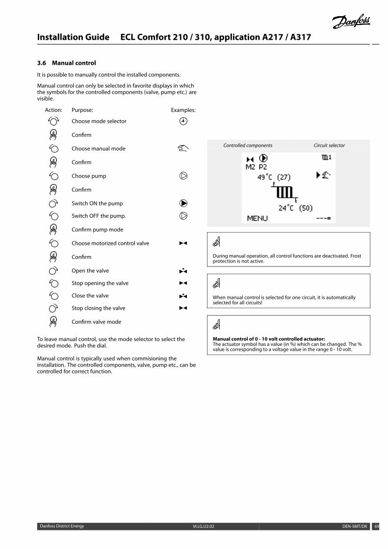
Installation Guide ECL Comfort 210 / 310, application A217 / A317
3.6 Manual control
It is possible to manually control the installed components.
Manual control can only be selected in favorite displays in whichthe symbols for the controlled components (valve, pump etc.) arevisible.
Action: Purpose: Examples:
Choose mode selector
Confirm
Choose manual mode
Confirm
Choose pump
Confirm
Switch ON the pump
Switch OFF the pump.
Confirm pump mode
Choose motorized control valve
Confirm
Open the valve
Stop opening the valve
Close the valve
Stop closing the valve
Confirm valve mode
To leave manual control, use the mode selector to select thedesired mode. Push the dial.
Manual control is typically used when commisioning theinstallation. The controlled components, valve, pump etc., can becontrolled for correct function.
Controlled components Circuit selector
During manual operation, all control functions are deactivated. Frostprotection is not active.
When manual control is selected for one circuit, it is automaticallyselected for all circuits!
Manual control of 0 - 10 volt controlled actuator:The actuator symbol has a value (in %) which can be changed. The %value is corresponding to a voltage value in the range 0 - 10 volt.
Danfoss District Energy VI.LG.U2.02 DEN-SMT/DK 69
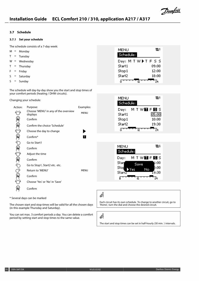
Installation Guide ECL Comfort 210 / 310, application A217 / A317
3.7 Schedule
3.7.1 Set your schedule
The schedule consists of a 7-day week:
M = Monday
T = Tuesday
W = Wednesday
T = Thursday
F = Friday
S = Saturday
S = Sunday
The schedule will day-by-day show you the start and stop times ofyour comfort periods (heating / DHW circuits).
Changing your schedule:
Action: Purpose: Examples:Choose 'MENU' in any of the overviewdisplays
Confirm
Confirm the choice 'Schedule'
Choose the day to change
Confirm* T
Go to Start1
Confirm
Adjust the time
Confirm
Go to Stop1, Start2 etc. etc.
Return to 'MENU'
Confirm
Choose 'Yes' or 'No' in 'Save'
Confirm
* Several days can be marked
The chosen start and stop times will be valid for all the chosen days(in this example Thursday and Saturday).
You can set max. 3 comfort periods a day. You can delete a comfortperiod by setting start and stop times to the same value.
Each circuit has its own schedule. To change to another circuit, go to'Home', turn the dial and choose the desired circuit.
The start and stop times can be set in half-hourly (30 min. ) intervals.
70 DEN-SMT/DK VI.LG.U2.02 Danfoss District Energy
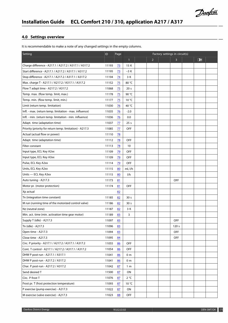
Installation Guide ECL Comfort 210 / 310, application A217 / A317
4.0 Settings overview
It is recommendable to make a note of any changed settings in the empty columns.
Setting ID Page Factory settings in circuit(s)
1 2 3
Charge difference - A217.1 / A217.2 / A317.1 / A317.2 11193 73 15 K
Start difference - A217.1 / A217.2 / A317.1 / A317.2 11195 73 –3 K
Stop difference - A217.1 / A217.2 / A317.1 / A317.2 11194 74 3 K
Max. charge T - A217.1 / A217.2 / A317.1 / A317.2 11152 75 80 °C
Flow T adapt time - A217.2 / A317.2 11068 75 20 s
Temp. max. (flow temp. limit, max.) 11178 75 90 °C
Temp. min. (flow temp. limit, min.) 11177 75 10 °C
Limit (return temp. limitation) 11030 76 40 °C
Infl. - max. (return temp. limitation - max. influence) 11035 76 -2.0
Infl. - min. (return temp. limitation - min. influence) 11036 76 0.0
Adapt. time (adaptation time) 11037 77 25 s
Priority (priority for return temp. limitation) - A217.3 11085 77 OFF
Actual (actual flow or power) 11110 78
Adapt. time (adaptation time) 11112 78 OFF
Filter constant 11113 78 10
Input type, ECL Key A2xx 11109 79 OFF
Input type, ECL Key A3xx 11109 79 OFF
Pulse, ECL Key A2xx 11114 79 OFF
Units, ECL Key A2xx 11115 80 ml, l/h
Units — ECL Key A3xx 11115 80 l/h
Auto tuning - A217.3 11173 81 OFF
Motor pr. (motor protection) 11174 81 OFF
Xp actual 82
Tn (integration time constant) 11185 82 30 s
M run (running time of the motorized control valve) 11186 82 30 s
Nz (neutral zone) 11187 82 3 K
Min. act. time (min. activation time gear motor) 11189 83 3
Supply T (idle) - A217.3 11097 83 OFF
Tn (idle) - A217.3 11096 83 120 s
Open time - A217.3 11094 83 OFF
Close time - A217.3 11095 84 OFF
Circ. P priority - A217.1 / A217.2 / A317.1 / A317.2 11055 86 OFF
Cont. T control - A217.1 / A217.2 / A317.1 / A317.2 11054 86 OFF
DHW P post-run - A217.1 / A317.1 11041 86 0 m
DHW P post-run - A217.2 / A317.2 11041 86 0 m
Char. P post-run - A217.2 / A317.2 11042 87 1 m
Send desired T 11500 87 ON
Circ. P frost T 11076 87 2 °C
Frost pr. T (frost protection temperature) 11093 87 10 °C
P exercise (pump exercise) - A217.3 11022 87 ON
M exercise (valve exercise) - A217.3 11023 88 OFF
Danfoss District Energy VI.LG.U2.02 DEN-SMT/DK 71
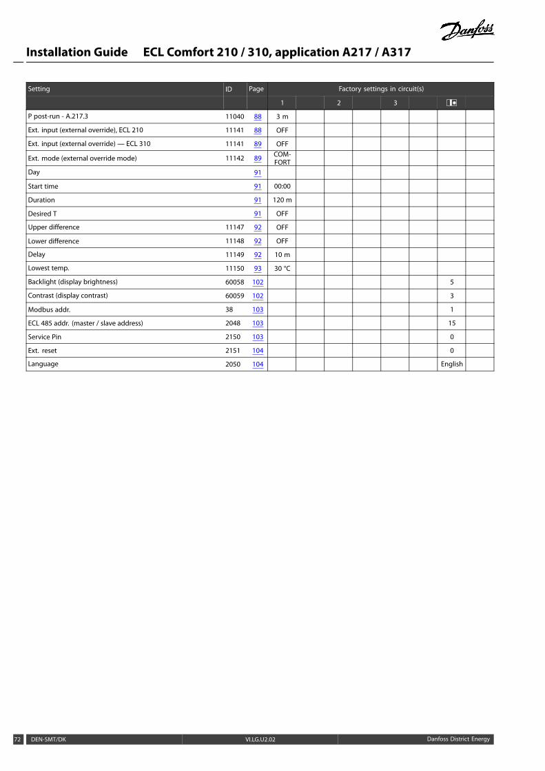
Installation Guide ECL Comfort 210 / 310, application A217 / A317
Setting ID Page Factory settings in circuit(s)
1 2 3
P post-run - A.217.3 11040 88 3 m
Ext. input (external override), ECL 210 11141 88 OFF
Ext. input (external override) — ECL 310 11141 89 OFF
Ext. mode (external override mode) 11142 89 COM-FORT
Day 91
Start time 91 00:00
Duration 91 120 m
Desired T 91 OFF
Upper difference 11147 92 OFF
Lower difference 11148 92 OFF
Delay 11149 92 10 m
Lowest temp. 11150 93 30 °C
Backlight (display brightness) 60058 102 5
Contrast (display contrast) 60059 102 3
Modbus addr. 38 103 1
ECL 485 addr. (master / slave address) 2048 103 15
Service Pin 2150 103 0
Ext. reset 2151 104 0
Language 2050 104 English
72 DEN-SMT/DK VI.LG.U2.02 Danfoss District Energy
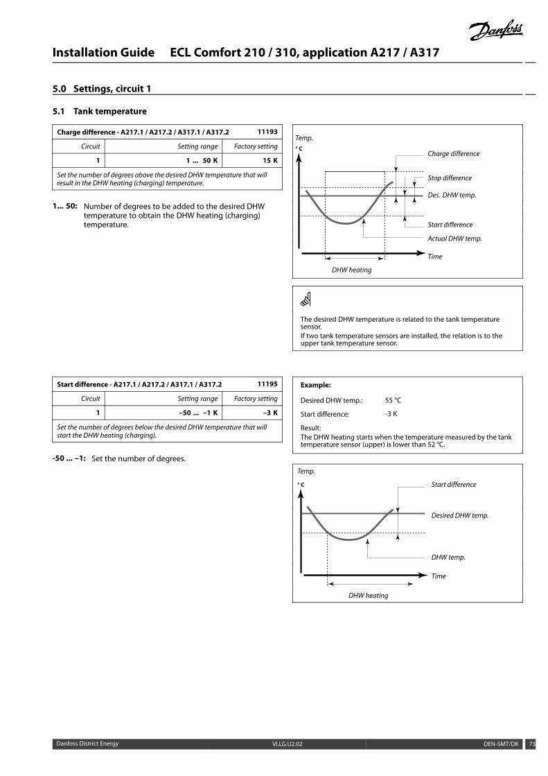
Installation Guide ECL Comfort 210 / 310, application A217 / A317
5.0 Settings, circuit 1
5.1 Tank temperature
Charge difference - A217.1 / A217.2 / A317.1 / A317.2 11193
Circuit Setting range Factory setting
1 1 ... 50 K 15 K
Set the number of degrees above the desired DHW temperature that willresult in the DHW heating (charging) temperature.
1... 50: Number of degrees to be added to the desired DHWtemperature to obtain the DHW heating (charging)temperature.
Temp.
Charge difference
Stop difference
Des. DHW temp.
Start difference
Actual DHW temp.
° C
Time
DHW heating
The desired DHW temperature is related to the tank temperaturesensor.If two tank temperature sensors are installed, the relation is to theupper tank temperature sensor.
Start difference - A217.1 / A217.2 / A317.1 / A317.2 11195
Circuit Setting range Factory setting
1 –50 ... –1 K –3 K
Set the number of degrees below the desired DHW temperature that willstart the DHW heating (charging).
-50 ... –1: Set the number of degrees.
Example:
Desired DHW temp.: 55 °C
Start difference: -3 K
Result:The DHW heating starts when the temperature measured by the tanktemperature sensor (upper) is lower than 52 °C.
Temp.
Start difference
Desired DHW temp.
DHW temp.
° C
Time
DHW heating
Danfoss District Energy VI.LG.U2.02 DEN-SMT/DK 73
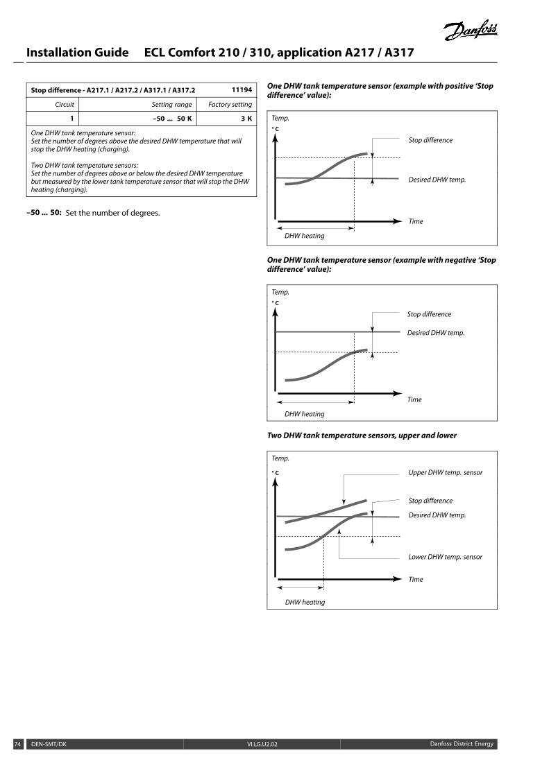
Installation Guide ECL Comfort 210 / 310, application A217 / A317
Stop difference - A217.1 / A217.2 / A317.1 / A317.2 11194
Circuit Setting range Factory setting
1 –50 ... 50 K 3 K
One DHW tank temperature sensor:Set the number of degrees above the desired DHW temperature that willstop the DHW heating (charging).
Two DHW tank temperature sensors:Set the number of degrees above or below the desired DHW temperaturebut measured by the lower tank temperature sensor that will stop the DHWheating (charging).
–50 ... 50: Set the number of degrees.
One DHW tank temperature sensor (example with positive ‘Stopdifference’ value):
Temp.
Stop difference
Desired DHW temp.
° C
Time
DHW heating
OneDHW tank temperature sensor (example with negative ‘Stopdifference’ value):
Temp.
Stop difference
Desired DHW temp.
° C
Time
DHW heating
TwoDHW tank temperature sensors, upper and lower
Temp.
Upper DHW temp. sensor
Stop difference
Desired DHW temp.
Lower DHW temp. sensor
° C
Time
DHW heating
74 DEN-SMT/DK VI.LG.U2.02 Danfoss District Energy
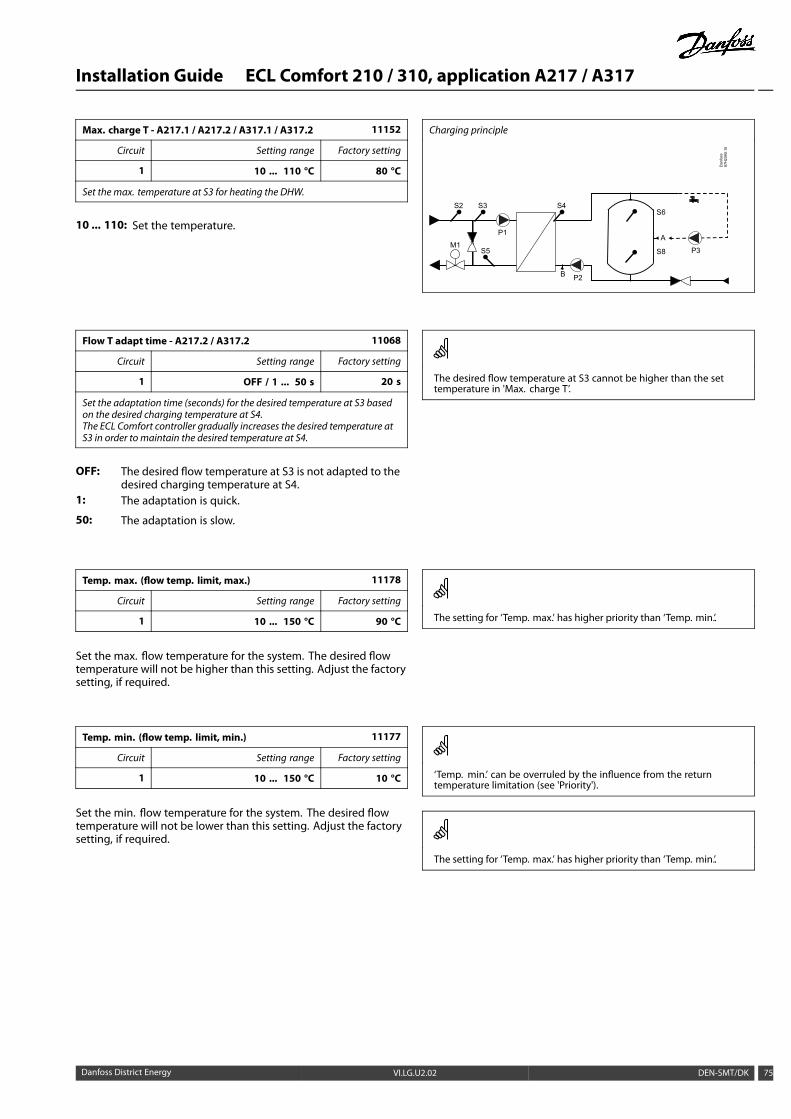
Installation Guide ECL Comfort 210 / 310, application A217 / A317
Max. charge T - A217.1 / A217.2 / A317.1 / A317.2 11152
Circuit Setting range Factory setting
1 10 ... 110 °C 80 °C
Set the max. temperature at S3 for heating the DHW.
10 ... 110: Set the temperature.
Charging principle
Dan
foss
87H
2090
.10
M1
P2
S4
S5
S6
S8 P3
A
B
S2 S3
P1
Flow T adapt time - A217.2 / A317.2 11068
Circuit Setting range Factory setting
1 OFF / 1 ... 50 s 20 s
Set the adaptation time (seconds) for the desired temperature at S3 basedon the desired charging temperature at S4.The ECL Comfort controller gradually increases the desired temperature atS3 in order to maintain the desired temperature at S4.
OFF: The desired flow temperature at S3 is not adapted to thedesired charging temperature at S4.
1: The adaptation is quick.
50: The adaptation is slow.
The desired flow temperature at S3 cannot be higher than the settemperature in 'Max. charge T’.
Temp. max. (flow temp. limit, max.) 11178
Circuit Setting range Factory setting
1 10 ... 150 °C 90 °C
Set the max. flow temperature for the system. The desired flowtemperature will not be higher than this setting. Adjust the factorysetting, if required.
The setting for ‘Temp. max.’ has higher priority than ‘Temp. min.’.
Temp. min. (flow temp. limit, min.) 11177
Circuit Setting range Factory setting
1 10 ... 150 °C 10 °C
Set the min. flow temperature for the system. The desired flowtemperature will not be lower than this setting. Adjust the factorysetting, if required.
‘Temp. min.’ can be overruled by the influence from the returntemperature limitation (see 'Priority').
The setting for ‘Temp. max.’ has higher priority than ‘Temp. min.’.
Danfoss District Energy VI.LG.U2.02 DEN-SMT/DK 75

Installation Guide ECL Comfort 210 / 310, application A217 / A317
5.2 Return limit
The return temperature limitation is based on a constanttemperature value.
The controller automatically changes the desired flow temperatureto obtain an acceptable return temperature when the returntemperature falls below or gets higher than the set limit.
This limitation is based on a PI regulation where P ('Infl.' factor)responds quickly to deviations and I ('Adapt. time') respondsslower and over time removes the small offsets between thedesired and actual values. This is done by changing the desiredflow temperature.
Influence
‘Infl. - min.’ > 0
‘Limit’
‘Infl. - max.’ > 0
Return temperature
‘Infl. - max.’ < 0
‘Infl. - min.’ < 0
If the ‘Infl.’ factor is too high and / or the ‘Adapt. time’ too low, there isa risk of unstable control.
Limit (return temp. limitation) 11030
Circuit Setting range Factory setting
1 10 ... 110 °C 40 °C
Set the return tempeature you accept for the system.
When the return temperature falls below or gets higher than theset value, the controller automatically changes the desired flowtemperature to obtain an acceptable return temperature. Theinfluence is set in 'Infl. - max.' and 'Infl. - min.'.
Infl. - max. (return temp. limitation - max. influence) 11035
Circuit Setting range Factory setting
1 -9.9 ... 9.9 -2.0
Determines howmuch the desired flow temperature will be influenced if thereturn temperature is higher than the calculated limit.
Influence higher than 0:The desired flow temperature is increased, when the returntemperature gets higher than the calculated limit.
Influence lower than 0:The desired flow temperature is decreased, when the returntemperature gets higher than the calculated limit.
ExampleThe return limit is active above 50 °C.The influence is set to -2.0.The actual return temperature is 2 degrees too high.Result:The desired flow temperature is changed by -2.0 x 2 = -4.0 degrees.
Normally, this setting is lower than 0 in district heating systems toavoid a too high return temperature.Typically, this setting is 0 in boiler systems because a higher returntemperature is acceptable (see also 'Infl. - min.').
Infl. - min. (return temp. limitation - min. influence) 11036
Circuit Setting range Factory setting
1 -9.9 ... 9.9 0.0
Determines howmuch the desired flow temperature will be influenced if thereturn temperature is lower than the calculated limit.
Influence higher than 0:The desired flow temperature is increased, when the returntemperature gets below the calculated limit.
Influence lower than 0:The desired flow temperature is decreased, when the returntemperature gets below the calculated limit.
ExampleThe return limit is active below 50 °C.The influence is set to -3.0.The actual return temperature is 2 degrees too low.Result:The desired flow temperature is changed by -3.0 x 2 = -6.0 degrees.
Normally, this setting is 0 in district heating systems because a lowerreturn temperature is acceptable.Typically, this setting is higher than 0 in boiler systems to avoid a toolow return temperature (see also 'Infl. - max.').
76 DEN-SMT/DK VI.LG.U2.02 Danfoss District Energy
Installation Guide ECL Comfort 210 / 310, application A217 / A317
Adapt. time (adaptation time) 11037
Circuit Setting range Factory setting
1 OFF / 1 ... 50 s 25 s
Controls how fast the return temperature adapts to the desired returntemperature limit (I control).
OFF: The control function is not influenced by the ‘Adapt.time’.
1: The desired temperature is adapted quickly.
50: The desired temperature is adapted slowly.
The adaptation function can correct the desired flow temperaturewith max. 8 K.
Priority (priority for return temp. limitation) - A217.3 11085
Circuit Setting range Factory setting
1 OFF / ON OFF
Choose whether the return temperature limitation should overrule the setmin. flow temperature ‘Temp. min.’ .
OFF: The min. flow temperature limit is not overruled.
ON: The min. flow temperature limit is overruled.
Danfoss District Energy VI.LG.U2.02 DEN-SMT/DK 77
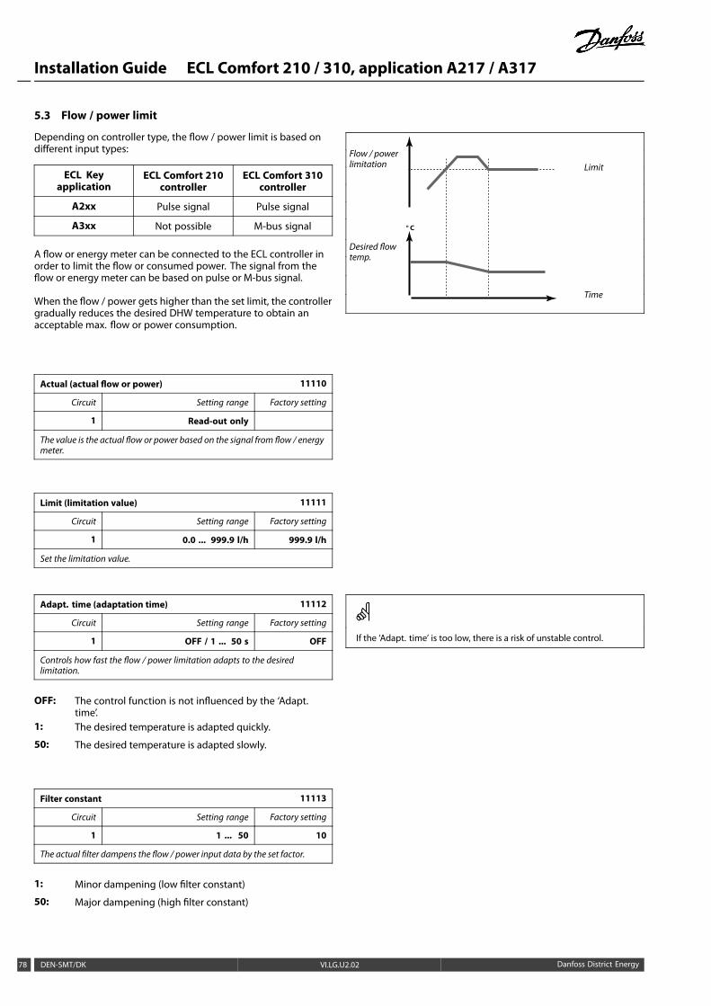
Installation Guide ECL Comfort 210 / 310, application A217 / A317
5.3 Flow / power limit
Depending on controller type, the flow / power limit is based ondifferent input types:
ECL Keyapplication
ECL Comfort 210controller
ECL Comfort 310controller
A2xx Pulse signal Pulse signal
A3xx Not possible M-bus signal
A flow or energy meter can be connected to the ECL controller inorder to limit the flow or consumed power. The signal from theflow or energy meter can be based on pulse or M-bus signal.
When the flow / power gets higher than the set limit, the controllergradually reduces the desired DHW temperature to obtain anacceptable max. flow or power consumption.
Flow / powerlimitation Limit
Desired flowtemp.
° C
Time
Actual (actual flow or power) 11110
Circuit Setting range Factory setting
1 Read-out only
The value is the actual flow or power based on the signal from flow / energymeter.
Limit (limitation value) 11111
Circuit Setting range Factory setting
1 0.0 ... 999.9 l/h 999.9 l/h
Set the limitation value.
Adapt. time (adaptation time) 11112
Circuit Setting range Factory setting
1 OFF / 1 ... 50 s OFF
Controls how fast the flow / power limitation adapts to the desiredlimitation.
OFF: The control function is not influenced by the ‘Adapt.time’.
1: The desired temperature is adapted quickly.
50: The desired temperature is adapted slowly.
If the ‘Adapt. time’ is too low, there is a risk of unstable control.
Filter constant 11113
Circuit Setting range Factory setting
1 1 ... 50 10
The actual filter dampens the flow / power input data by the set factor.
1: Minor dampening (low filter constant)
50: Major dampening (high filter constant)
78 DEN-SMT/DK VI.LG.U2.02 Danfoss District Energy
Installation Guide ECL Comfort 210 / 310, application A217 / A317
Input type, ECL Key A2xx 11109
Circuit Setting range Factory setting
1 OFF / IM1 OFF
Choice of pulse type signal applied to input S7. Possible in ECL Comfort 210as well as ECL Comfort 310 controllers.
OFF: No input.
IM1: Pulse.
Flow or power limitation is based on pulse signals.
Input type, ECL Key A3xx 11109
Circuit Setting range Factory setting
1 OFF / EM1 ... EM5 OFF
Choice of M-bus signal from energy meter number 1 ... 5. Only possiblein ECL Comfort 310.
OFF: No M-bus signal acquired.
EM1 ... EM5: Energy meter number.
Flow or power limitation is based on M-bus signal (ECL Comfort 310controllers only).
Pulse, ECL Key A2xx 11114
Circuit Setting range Factory setting
1 OFF / 1 ... 9999 OFF
Set the value of the pulses from the flow / heat meter.
OFF: No input.
1 ... 9999: Pulse value.
Example :
One pulse can represent a number of litres (from a flow meter)or a number of kWh (from a heat meter).
Danfoss District Energy VI.LG.U2.02 DEN-SMT/DK 79
Installation Guide ECL Comfort 210 / 310, application A217 / A317
Units, ECL Key A2xx 11115
Circuit Setting range Factory setting
1 See the list ml, l/h
Choice of units for measured values. Choose a value in the range 1 ... 9999in ‘Pulse’.
Units to the left: pulse value.Units to the right: actual and limitation values.
The value from the flow meter is expressed as ml or l.The value from the heat meter is expressed as Wh, kWh, MWh orGWh.
The values for the actual flow and the flow limitation are expressedas l/h or m³/h.
The values for the actual power and the power limitation areexpressed as kW, MW or GW.
List for setting range of 'Units':ml, l/hl, l/hml, m³/hl, m³/hWh, kWkWh, kWkWh, MWMWh, MWMWh, GWGWh, GW
Example 1:
'Units' (11115): l, m³/h
'Pulse' (11114): 10
Each pulse represents 10 litres and the flow is expressed as cubicmeters (m³) per hour.
Example 2:
'Units' (11115): kWh, kW (= kilo Watt hour, kilo Watt)
'Pulse' (11114): 1
Each pulse represents 1 kilo Watt hour and the power isexpressed in kilo Watt.
Units — ECL Key A3xx 11115
Circuit Setting range Factory setting
1 See the list l/h
Choice of units for measured values.
Flow values are expressed as l/h or m³/hPower values are expressed as kW, MW or GW.
List for setting range of 'Units':l/hm³/hkWMWGW
80 DEN-SMT/DK VI.LG.U2.02 Danfoss District Energy
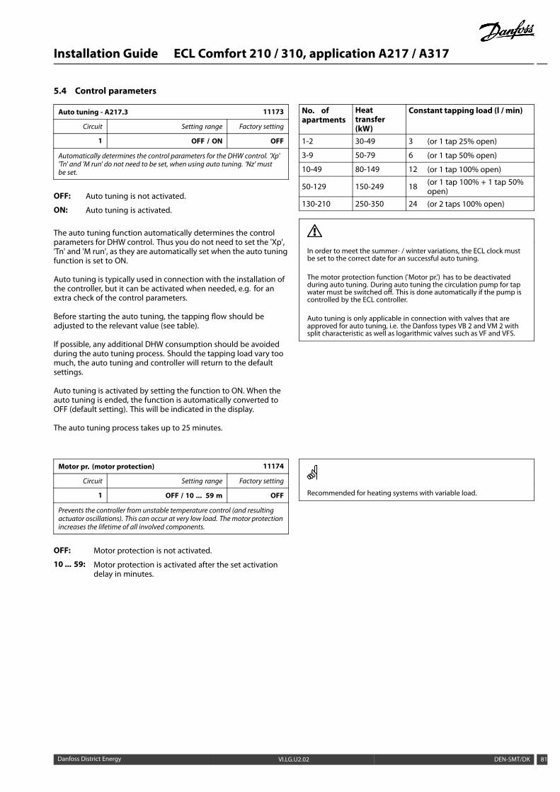
Installation Guide ECL Comfort 210 / 310, application A217 / A317
5.4 Control parameters
Auto tuning - A217.3 11173
Circuit Setting range Factory setting
1 OFF / ON OFF
Automatically determines the control parameters for the DHW control. 'Xp''Tn' and 'M run' do not need to be set, when using auto tuning. 'Nz' mustbe set.
OFF: Auto tuning is not activated.
ON: Auto tuning is activated.
The auto tuning function automatically determines the controlparameters for DHW control. Thus you do not need to set the 'Xp','Tn' and 'M run', as they are automatically set when the auto tuningfunction is set to ON.
Auto tuning is typically used in connection with the installation ofthe controller, but it can be activated when needed, e.g. for anextra check of the control parameters.
Before starting the auto tuning, the tapping flow should beadjusted to the relevant value (see table).
If possible, any additional DHW consumption should be avoidedduring the auto tuning process. Should the tapping load vary toomuch, the auto tuning and controller will return to the defaultsettings.
Auto tuning is activated by setting the function to ON. When theauto tuning is ended, the function is automatically converted toOFF (default setting). This will be indicated in the display.
The auto tuning process takes up to 25 minutes.
No. ofapartments
Heattransfer(kW)
Constant tapping load (l / min)
1-2 30-49 3 (or 1 tap 25% open)
3-9 50-79 6 (or 1 tap 50% open)
10-49 80-149 12 (or 1 tap 100% open)
50-129 150-249 18 (or 1 tap 100% + 1 tap 50%open)
130-210 250-350 24 (or 2 taps 100% open)
In order to meet the summer- / winter variations, the ECL clock mustbe set to the correct date for an successful auto tuning.
The motor protection function ('Motor pr.') has to be deactivatedduring auto tuning. During auto tuning the circulation pump for tapwater must be switched off. This is done automatically if the pump iscontrolled by the ECL controller.
Auto tuning is only applicable in connection with valves that areapproved for auto tuning, i.e. the Danfoss types VB 2 and VM 2 withsplit characteristic as well as logarithmic valves such as VF and VFS.
Motor pr. (motor protection) 11174
Circuit Setting range Factory setting
1 OFF / 10 ... 59 m OFF
Prevents the controller from unstable temperature control (and resultingactuator oscillations). This can occur at very low load. Themotor protectionincreases the lifetime of all involved components.
OFF: Motor protection is not activated.
10 ... 59: Motor protection is activated after the set activationdelay in minutes.
Recommended for heating systems with variable load.
Danfoss District Energy VI.LG.U2.02 DEN-SMT/DK 81
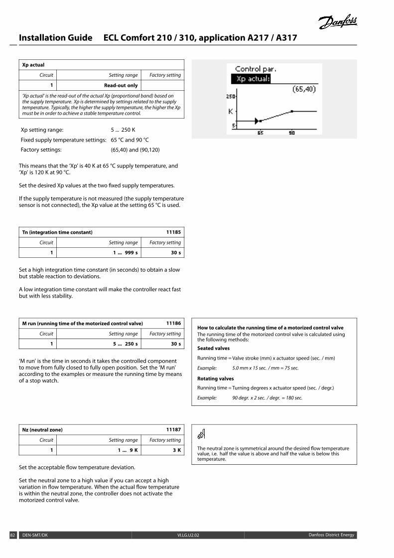
Installation Guide ECL Comfort 210 / 310, application A217 / A317
Xp actual
Circuit Setting range Factory setting
1 Read-out only
‘Xp actual’ is the read-out of the actual Xp (proportional band) based onthe supply temperature. Xp is determined by settings related to the supplytemperature. Typically, the higher the supply temperature, the higher the Xpmust be in order to achieve a stable temperature control.
Xp setting range: 5 ... 250 K
Fixed supply temperature settings: 65 °C and 90 °C
Factory settings: (65,40) and (90,120)
This means that the ‘Xp’ is 40 K at 65 °C supply temperature, and‘Xp’ is 120 K at 90 °C.
Set the desired Xp values at the two fixed supply temperatures.
If the supply temperature is not measured (the supply temperaturesensor is not connected), the Xp value at the setting 65 °C is used.
Tn (integration time constant) 11185
Circuit Setting range Factory setting
1 1 ... 999 s 30 s
Set a high integration time constant (in seconds) to obtain a slowbut stable reaction to deviations.
A low integration time constant will make the controller react fastbut with less stability.
M run (running time of the motorized control valve) 11186
Circuit Setting range Factory setting
1 5 ... 250 s 30 s
‘M run’ is the time in seconds it takes the controlled componentto move from fully closed to fully open position. Set the ‘M run’according to the examples or measure the running time by meansof a stop watch.
How to calculate the running time of a motorized control valveThe running time of the motorized control valve is calculated usingthe following methods:
Seated valves
Running time =Valve stroke (mm) x actuator speed (sec. / mm)
Example: 5.0 mm x 15 sec. / mm = 75 sec.
Rotating valves
Running time =Turning degrees x actuator speed (sec. / degr.)
Example: 90 degr. x 2 sec. / degr. = 180 sec.
Nz (neutral zone) 11187
Circuit Setting range Factory setting
1 1 ... 9 K 3 K
Set the acceptable flow temperature deviation.
Set the neutral zone to a high value if you can accept a highvariation in flow temperature. When the actual flow temperatureis within the neutral zone, the controller does not activate themotorized control valve.
The neutral zone is symmetrical around the desired flow temperaturevalue, i.e. half the value is above and half the value is below thistemperature.
82 DEN-SMT/DK VI.LG.U2.02 Danfoss District Energy
Installation Guide ECL Comfort 210 / 310, application A217 / A317
Min. act. time (min. activation time gear motor) 11189
Circuit Setting range Factory setting
1 2 ... 50 3
The min. pulse period of 20 ms (milliseconds ) for activation of the gearmotor.
Setting example Value x 20 ms
2 40 ms
10 200 ms
50 1000 ms
The setting should be kept as high as acceptable to increase thelifetime of the actuator (gear motor).
Supply T (idle) - A217.3 11097
Circuit Setting range Factory setting
1 OFF / ON OFF
The ‘supply T (idle)’ is the supply temperature when there is no DHW tapping/ DHW draw-off. When DHW tapping / DHW draw-off is not detected (theflow switch is deactivated), the temperature is maintained at a (typical)lower level (saving temperature). Choose which temperature sensor is tomaintain the saving temperature.
OFF: The saving temperature is maintained at the DHW flowtemperature sensor (S3).
ON: The saving temperature is maintained at the supplytemperature sensor (S2).
If the S2 temperature sensor is not connected, the idle supplytemperature will be maintained at S3.The ‘supply T (idle)’ function is only active if a value is chosen in 11094.
Tn (idle) - A217.3 11096
Circuit Setting range Factory setting
3 1 ... 999 s 120 s
Integration time is a constant when no DHW tapping / DHW draw-off isdetected (the flow switch is deactivated), for slowly control of the savingtemperature at either S3 or S2 (see also the setting in 11097).
Set a high integration time constant to obtain a slow control.
Set a low integration time constant for a fast control.
Open time - A217.3 11094
Circuit Setting range Factory setting
1 OFF / 0.1... 25.0 s OFF
Commands the actuator to open the valve for the set period when aDHW tapping / DHW draw-off starts. The DHW tapping / DHW draw-offis detected by the activated flow switch (S8). The ‘open time’ functioncompensates for the delay before the flow temperature sensor measures achange in temperature.
OFF: The flow switch function is disabled.
0.1 .... 25.0 s: Commanded opening time.
Danfoss District Energy VI.LG.U2.02 DEN-SMT/DK 83

Installation Guide ECL Comfort 210 / 310, application A217 / A317
Close time - A217.3 11095
Circuit Setting range Factory setting
1 OFF / 0.1 ... 25.0 s OFF
Commands the actuator to close the valve for the set period when a DHWtapping / DHW draw-off stops. When no DHW tapping / DHW draw-off ispresent, the flow switch (S8) is deactivated.
OFF: Commanded closing time is 0 (zero) sec.
0.1 .... 25.0 s: Commanded closing time.
84 DEN-SMT/DK VI.LG.U2.02 Danfoss District Energy
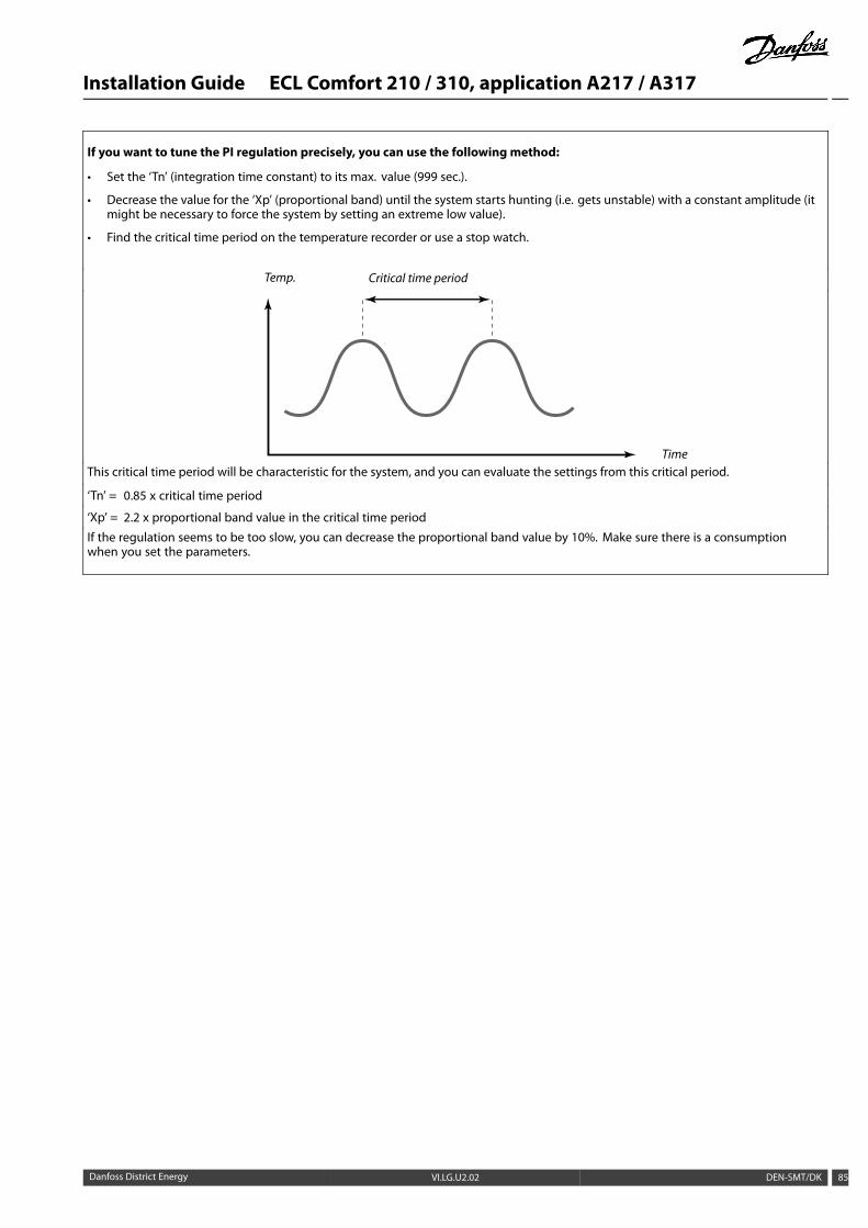
Installation Guide ECL Comfort 210 / 310, application A217 / A317
If you want to tune the PI regulation precisely, you can use the following method:
• Set the ‘Tn’ (integration time constant) to its max. value (999 sec.).
• Decrease the value for the ‘Xp’ (proportional band) until the system starts hunting (i.e. gets unstable) with a constant amplitude (itmight be necessary to force the system by setting an extreme low value).
• Find the critical time period on the temperature recorder or use a stop watch.
Temp. Critical time period
TimeThis critical time period will be characteristic for the system, and you can evaluate the settings from this critical period.
‘Tn’ = 0.85 x critical time period
‘Xp’ = 2.2 x proportional band value in the critical time period
If the regulation seems to be too slow, you can decrease the proportional band value by 10%. Make sure there is a consumptionwhen you set the parameters.
Danfoss District Energy VI.LG.U2.02 DEN-SMT/DK 85
Installation Guide ECL Comfort 210 / 310, application A217 / A317
5.5 Application
Circ. P priority - A217.1 / A217.2 / A317.1 / A317.2 11055
Circuit Setting range Factory setting
1 OFF / ON OFF
Choose whether the DHW circulation pump should be ON during DHWheating.
OFF: The DHW circulation pump is switched OFF during DHWheating.
ON: The DHW circulation pump is not switched OFF duringDHW heating.
When the 'Circ. P priority' is set to OFF, the schedule for the DHWcirculation pump is overruled.
Cont. T control - A217.1 / A217.2 / A317.1 / A317.2 11054
Circuit Setting range Factory setting
1 OFF / ON OFF
Depending on the DHW circulation pipe connection, the desired DHWheating / charging temperature can be lowered when the DHW heatingprocedure has elapsed.
OFF: The desired temperature at S3 or S4 is lowered to 10 °C.Typically, the DHW is circulated through the DHW tank.
ON: The desired temperature at S3 or S4 is lowered tothe desired DHW temperature. Typically, the DHWis circulated through the heat exchanger in order tocompensate for the heat loss in the DHW circulationpipe.
DHW P post-run - A217.1 / A317.1 11041
Circuit Setting range Factory setting
1 0 ... 30 m 0 m
Set the DHW heating / charging pump (P1) post-run time (minutes). Thepump can continue to be switched ON after the DHW heating procedure inorder to utilize the remaining heat in the heat exchanger / boiler.
0 ... 30: Set the number of minutes for the post-run.
DHW P post-run - A217.2 / A317.2 11041
Circuit Setting range Factory setting
1 0 ... 30 m 0 m
Set the DHWheating pump (P1) post-run time (minutes). The DHWheatingpump can continue to be switched ON after the DHW heating procedure inorder to utilize the remaining heat in the heat exchanger / boiler.
0 ... 30: Set the number of minutes for the post-run.
86 DEN-SMT/DK VI.LG.U2.02 Danfoss District Energy
Installation Guide ECL Comfort 210 / 310, application A217 / A317
Char. P post-run - A217.2 / A317.2 11042
Circuit Setting range Factory setting
1 0 ... 30 m 1 m
Set the DHW charging pump (P2) post-run time (minutes). The DHWcharging pump can continue to be switched ON after the DHW heatingprocedure in order to utilize the remaining heat in the heat exchanger.
0 ... 30: Set the number of minutes for the post-run.
Send desired T 11500
Circuit Setting range Factory setting
1 OFF / ON ON
When the controller acts as a slave controller in a master / slave system,information about the desired flow temperature can be sent to the mastercontroller via the ECL 485 bus.
OFF: Information about the desired flow temperature is notsent to the master controller.
ON: Information about the desired flow temperature is sentto the master controller.
In themaster controller, 'Demand offset' must be set to a value in orderto react on a desired flow temperature from a slave controller.
When the controller acts as a slave, its address must be 1, 2, 3 ... 9 inorder to send the desired temperature to the master (see the section‘Miscellaneous’, ‘Several controllers in the same system’).
Circ. P frost T 11076
Circuit Setting range Factory setting
1 OFF / –10 ... 20 °C 2 °C
Set the outdoor temperature value at which the DHW circulation pump is tobe active to protect the DHW circuit against frost.
OFF: The DHW circulation pump is not active.
–10 ... 20: The DHW circulation pump is active when the outdoortemperature is lower than the set value.
Frost pr. T (frost protection temperature) 11093
Circuit Setting range Factory setting
1 5 ... 40 °C 10 °C
Set the desired flow temperature (S3) to protect the system against frost.
5 ... 40: Desired frost protection temperature.
P exercise (pump exercise) - A217.3 11022
Circuit Setting range Factory setting
1 OFF / ON ON
Exercises the pump to avoid blocking in periods without DHW heatingdemand.
OFF: The pump exercise is not active.
ON: The pump is switched ON for 1 minute every third day atnoon (12:14 hours).
Danfoss District Energy VI.LG.U2.02 DEN-SMT/DK 87
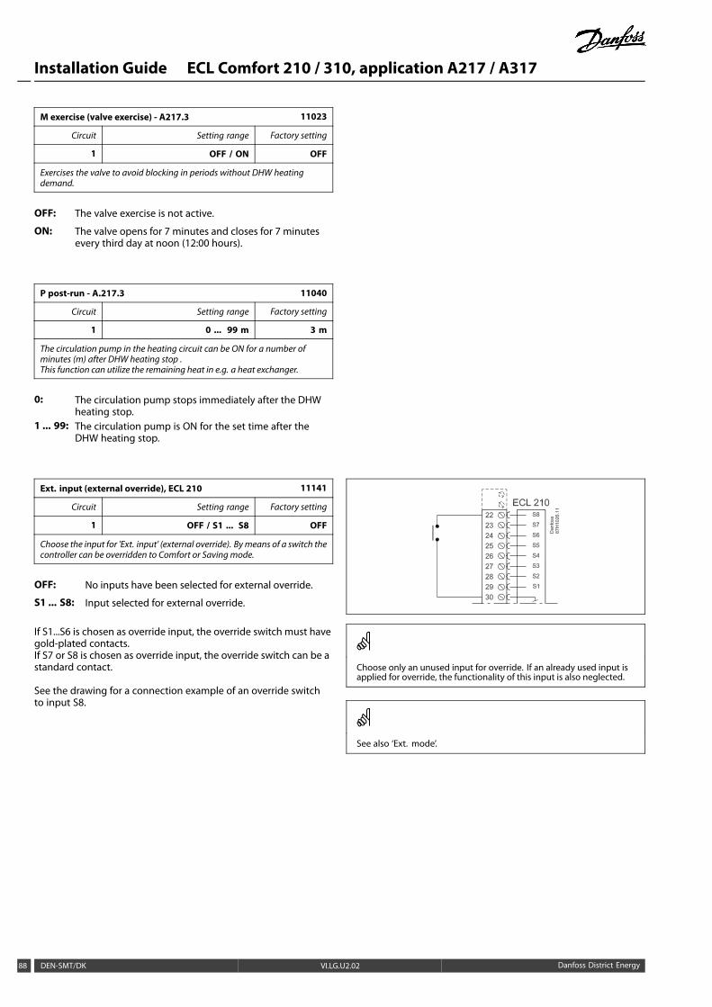
Installation Guide ECL Comfort 210 / 310, application A217 / A317
M exercise (valve exercise) - A217.3 11023
Circuit Setting range Factory setting
1 OFF / ON OFF
Exercises the valve to avoid blocking in periods without DHW heatingdemand.
OFF: The valve exercise is not active.
ON: The valve opens for 7 minutes and closes for 7 minutesevery third day at noon (12:00 hours).
P post-run - A.217.3 11040
Circuit Setting range Factory setting
1 0 ... 99 m 3 m
The circulation pump in the heating circuit can be ON for a number ofminutes (m) after DHW heating stop .This function can utilize the remaining heat in e.g. a heat exchanger.
0: The circulation pump stops immediately after the DHWheating stop.
1 ... 99: The circulation pump is ON for the set time after theDHW heating stop.
Ext. input (external override), ECL 210 11141
Circuit Setting range Factory setting
1 OFF / S1 ... S8 OFF
Choose the input for 'Ext. input' (external override). Bymeans of a switch thecontroller can be overridden to Comfort or Savingmode.
OFF: No inputs have been selected for external override.
S1 ... S8: Input selected for external override.
If S1...S6 is chosen as override input, the override switch must havegold-plated contacts.If S7 or S8 is chosen as override input, the override switch can be astandard contact.
See the drawing for a connection example of an override switchto input S8.
Choose only an unused input for override. If an already used input isapplied for override, the functionality of this input is also neglected.
See also ‘Ext. mode’.
88 DEN-SMT/DK VI.LG.U2.02 Danfoss District Energy
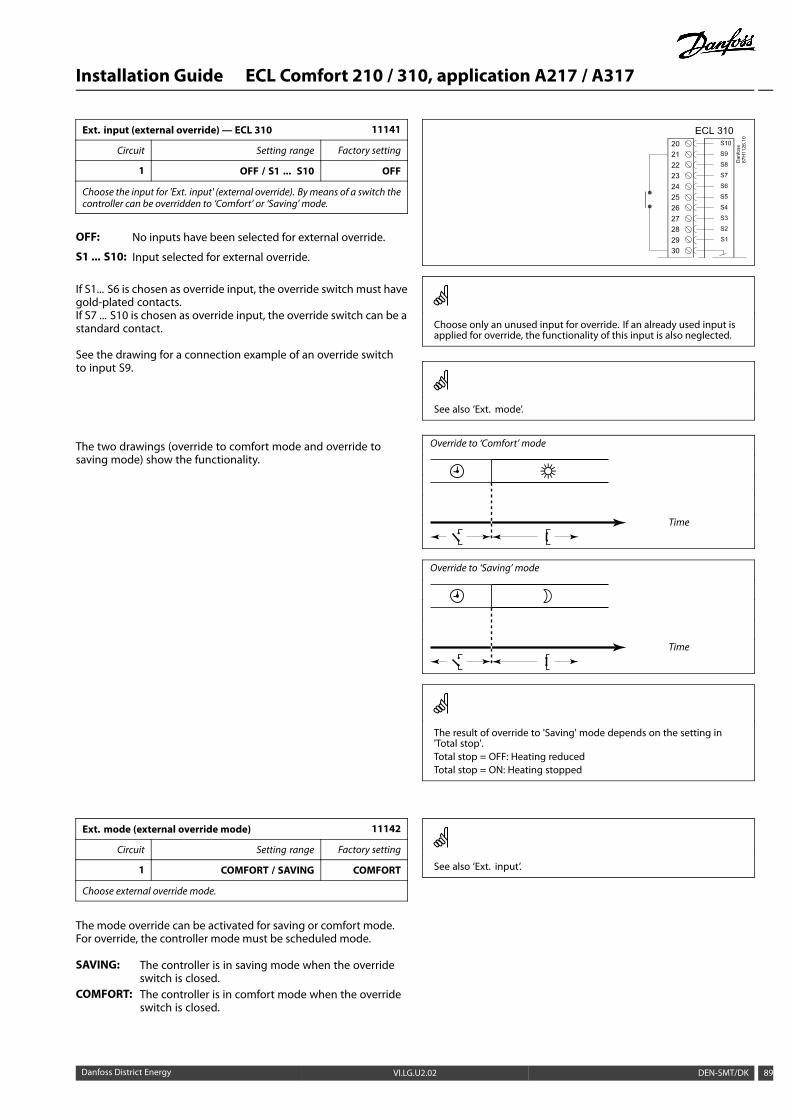
Installation Guide ECL Comfort 210 / 310, application A217 / A317
Ext. input (external override) — ECL 310 11141
Circuit Setting range Factory setting
1 OFF / S1 ... S10 OFF
Choose the input for 'Ext. input' (external override). Bymeans of a switch thecontroller can be overridden to ‘Comfort’ or ‘Saving’ mode.
OFF: No inputs have been selected for external override.
S1 ... S10: Input selected for external override.
If S1... S6 is chosen as override input, the override switch must havegold-plated contacts.If S7 ... S10 is chosen as override input, the override switch can be astandard contact.
See the drawing for a connection example of an override switchto input S9.
The two drawings (override to comfort mode and override tosaving mode) show the functionality.
Choose only an unused input for override. If an already used input isapplied for override, the functionality of this input is also neglected.
See also ‘Ext. mode’.
Override to ‘Comfort’ mode
Time
Override to ‘Saving’ mode
Time
The result of override to 'Saving' mode depends on the setting in'Total stop'.Total stop = OFF: Heating reducedTotal stop = ON: Heating stopped
Ext. mode (external override mode) 11142
Circuit Setting range Factory setting
1 COMFORT / SAVING COMFORT
Choose external override mode.
The mode override can be activated for saving or comfort mode.For override, the controller mode must be scheduled mode.
SAVING: The controller is in saving mode when the overrideswitch is closed.
COMFORT: The controller is in comfort mode when the overrideswitch is closed.
See also ‘Ext. input’.
Danfoss District Energy VI.LG.U2.02 DEN-SMT/DK 89
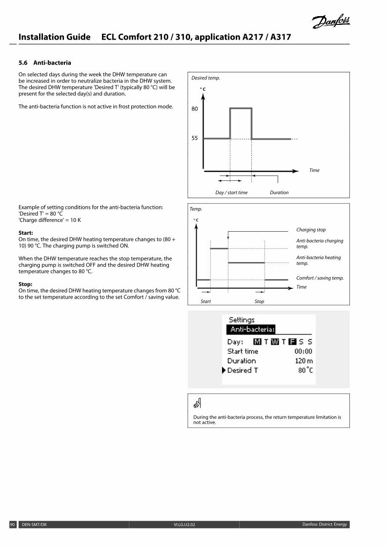
Installation Guide ECL Comfort 210 / 310, application A217 / A317
5.6 Anti-bacteria
On selected days during the week the DHW temperature canbe increased in order to neutralize bacteria in the DHW system.The desired DHW temperature 'Desired T' (typically 80 °C) will bepresent for the selected day(s) and duration.
The anti-bacteria function is not active in frost protection mode.
Example of setting conditions for the anti-bacteria function:'Desired T' = 80 °C'Charge difference' = 10 K
Start:On time, the desired DHW heating temperature changes to (80 +10) 90 °C. The charging pump is switched ON.
When the DHW temperature reaches the stop temperature, thecharging pump is switched OFF and the desired DHW heatingtemperature changes to 80 °C.
Stop:On time, the desired DHW heating temperature changes from 80 °Cto the set temperature according to the set Comfort / saving value.
Desired temp.
° C
80
55
Time
Day / start time Duration
Temp.
Charging stop
Anti-bacteria chargingtemp.
Anti-bacteria heatingtemp.
Comfort / saving temp.
° C
Time
Start Stop
During the anti-bacteria process, the return temperature limitation isnot active.
90 DEN-SMT/DK VI.LG.U2.02 Danfoss District Energy
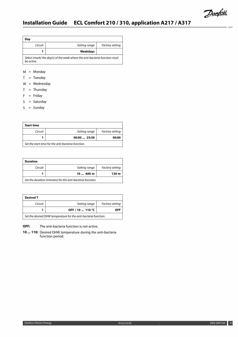
Installation Guide ECL Comfort 210 / 310, application A217 / A317
Day
Circuit Setting range Factory setting
1 Weekdays
Select (mark) the day(s) of the week where the anti-bacteria functionmustbe active.
M = Monday
T = Tuesday
W = Wednesday
T = Thursday
F = Friday
S = Saturday
S = Sunday
Start time
Circuit Setting range Factory setting
1 00:00 ... 23:30 00:00
Set the start time for the anti-bacteria function.
Duration
Circuit Setting range Factory setting
1 10 ... 600 m 120 m
Set the duration (minutes) for the anti-bacteria function.
Desired T
Circuit Setting range Factory setting
1 OFF / 10 ... 110 °C OFF
Set the desired DHW temperature for the anti-bacteria function.
OFF: The anti-bacteria function is not active.
10 ... 110: Desired DHW temperature during the anti-bacteriafunction period.
Danfoss District Energy VI.LG.U2.02 DEN-SMT/DK 91
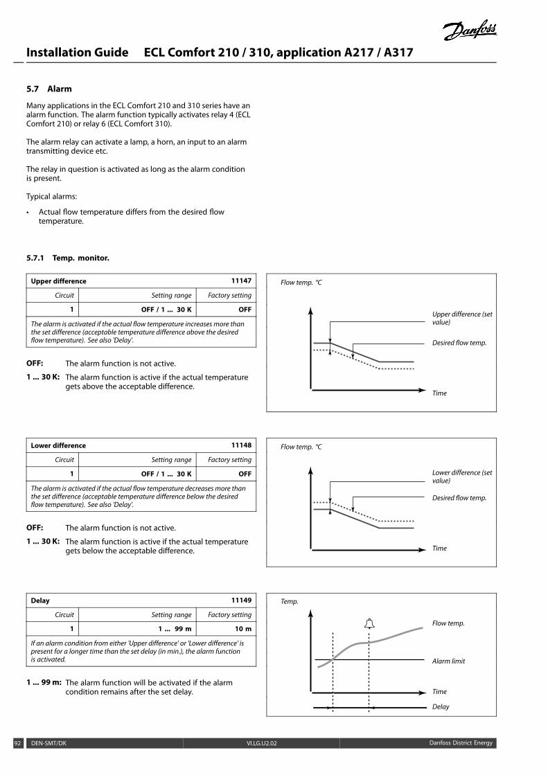
Installation Guide ECL Comfort 210 / 310, application A217 / A317
5.7 Alarm
Many applications in the ECL Comfort 210 and 310 series have analarm function. The alarm function typically activates relay 4 (ECLComfort 210) or relay 6 (ECL Comfort 310).
The alarm relay can activate a lamp, a horn, an input to an alarmtransmitting device etc.
The relay in question is activated as long as the alarm conditionis present.
Typical alarms:
• Actual flow temperature differs from the desired flowtemperature.
5.7.1 Temp. monitor.
Upper difference 11147
Circuit Setting range Factory setting
1 OFF / 1 ... 30 K OFF
The alarm is activated if the actual flow temperature increases more thanthe set difference (acceptable temperature difference above the desiredflow temperature). See also 'Delay'.
OFF: The alarm function is not active.
1 ... 30 K: The alarm function is active if the actual temperaturegets above the acceptable difference.
Flow temp. °C
Upper difference (setvalue)
Desired flow temp.
Time
Lower difference 11148
Circuit Setting range Factory setting
1 OFF / 1 ... 30 K OFF
The alarm is activated if the actual flow temperature decreases more thanthe set difference (acceptable temperature difference below the desiredflow temperature). See also 'Delay'.
OFF: The alarm function is not active.
1 ... 30 K: The alarm function is active if the actual temperaturegets below the acceptable difference.
Flow temp. °C
Lower difference (setvalue)
Desired flow temp.
Time
Delay 11149
Circuit Setting range Factory setting
1 1 ... 99 m 10 m
If an alarm condition from either 'Upper difference' or 'Lower difference' ispresent for a longer time than the set delay (in min.), the alarm functionis activated.
1 ... 99 m: The alarm function will be activated if the alarmcondition remains after the set delay.
Temp.
Flow temp.
Alarm limit
Time
Delay
92 DEN-SMT/DK VI.LG.U2.02 Danfoss District Energy

Installation Guide ECL Comfort 210 / 310, application A217 / A317
Lowest temp. 11150
Circuit Setting range Factory setting
1 10 ... 50 °C 30 °C
The alarm function will not be activated if the desired flow / ducttemperature is lower than the set value.
If the cause of the alarm disappears, the alarm indication and outputalso disappear.
Danfoss District Energy VI.LG.U2.02 DEN-SMT/DK 93
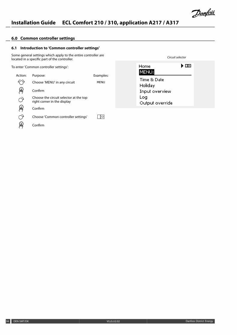
Installation Guide ECL Comfort 210 / 310, application A217 / A317
6.0 Common controller settings
6.1 Introduction to ‘Common controller settings’
Some general settings which apply to the entire controller arelocated in a specific part of the controller.
To enter ‘Common controller settings’:
Action: Purpose: Examples:
Choose ‘MENU’ in any circuit
Confirm
Choose the circuit selector at the topright corner in the display
Confirm
Choose ‘Common controller settings’
Confirm
Circuit selector
94 DEN-SMT/DK VI.LG.U2.02 Danfoss District Energy
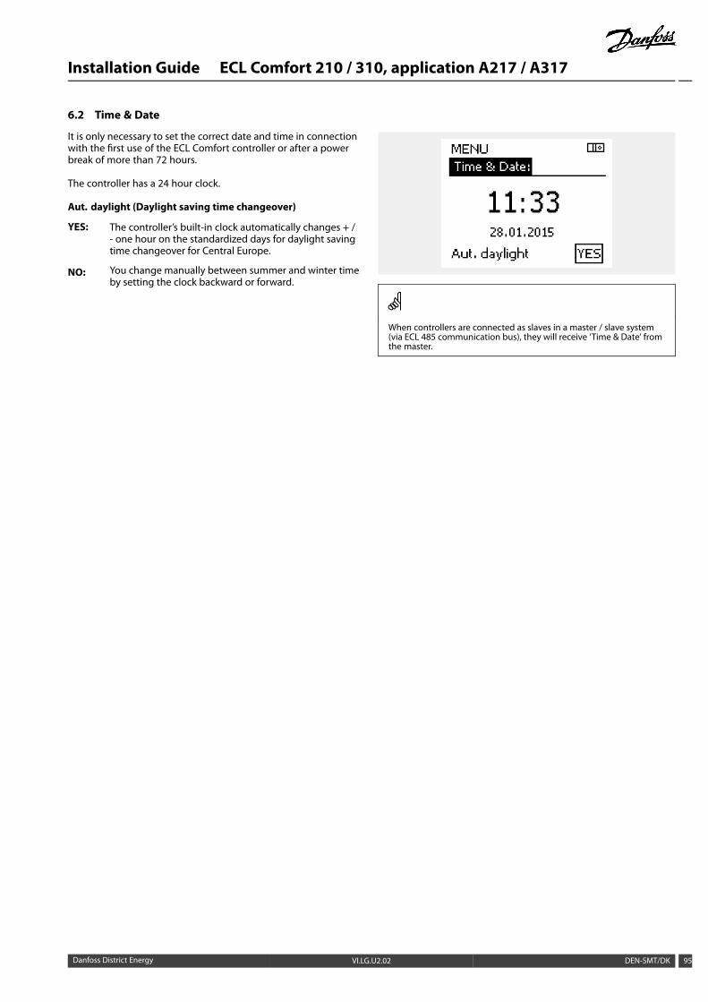
Installation Guide ECL Comfort 210 / 310, application A217 / A317
6.2 Time & Date
It is only necessary to set the correct date and time in connectionwith the first use of the ECL Comfort controller or after a powerbreak of more than 72 hours.
The controller has a 24 hour clock.
Aut. daylight (Daylight saving time changeover)
YES: The controller’s built-in clock automatically changes + /- one hour on the standardized days for daylight savingtime changeover for Central Europe.
NO: You change manually between summer and winter timeby setting the clock backward or forward.
When controllers are connected as slaves in a master / slave system(via ECL 485 communication bus), they will receive ‘Time & Date’ fromthe master.
Danfoss District Energy VI.LG.U2.02 DEN-SMT/DK 95
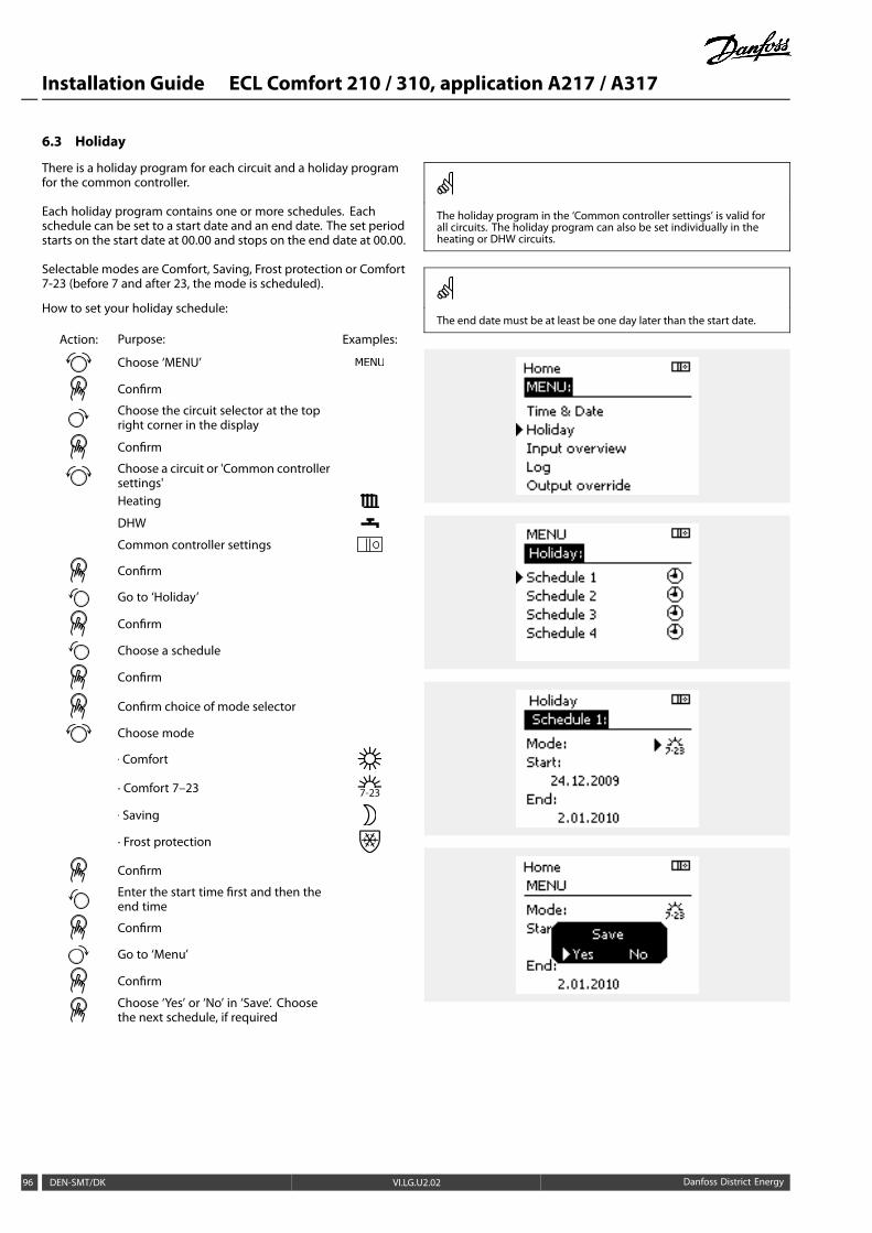
Installation Guide ECL Comfort 210 / 310, application A217 / A317
6.3 Holiday
There is a holiday program for each circuit and a holiday programfor the common controller.
Each holiday program contains one or more schedules. Eachschedule can be set to a start date and an end date. The set periodstarts on the start date at 00.00 and stops on the end date at 00.00.
Selectable modes are Comfort, Saving, Frost protection or Comfort7-23 (before 7 and after 23, the mode is scheduled).
How to set your holiday schedule:
Action: Purpose: Examples:
Choose ‘MENU’
Confirm
Choose the circuit selector at the topright corner in the display
Confirm
Choose a circuit or 'Common controllersettings'Heating
DHW
Common controller settings
Confirm
Go to ‘Holiday’
Confirm
Choose a schedule
Confirm
Confirm choice of mode selector
Choose mode
. Comfort
∙ Comfort 7–23 7-23
. Saving
∙ Frost protection
Confirm
Enter the start time first and then theend time
Confirm
Go to ‘Menu’
Confirm
Choose ‘Yes’ or ‘No’ in ‘Save’. Choosethe next schedule, if required
The holiday program in the ‘Common controller settings’ is valid forall circuits. The holiday program can also be set individually in theheating or DHW circuits.
The end date must be at least be one day later than the start date.
96 DEN-SMT/DK VI.LG.U2.02 Danfoss District Energy
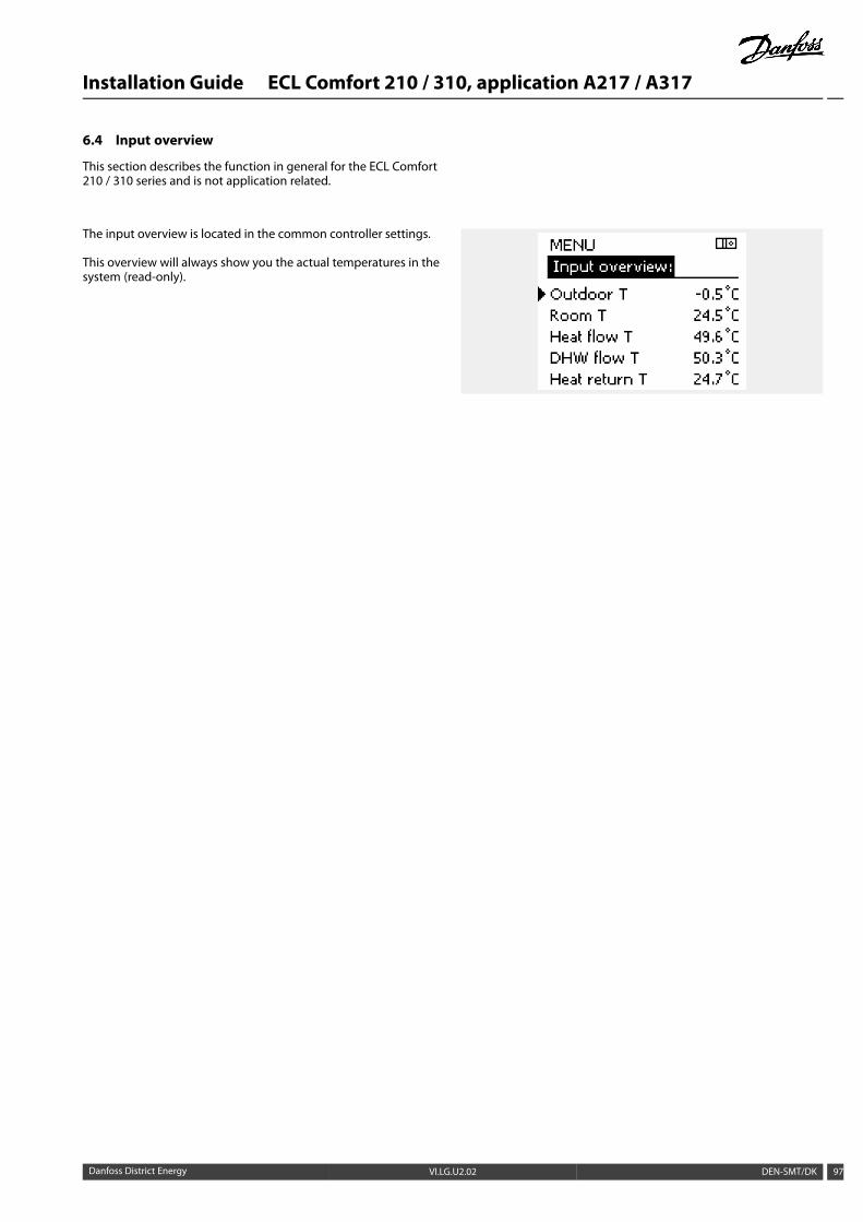
Installation Guide ECL Comfort 210 / 310, application A217 / A317
6.4 Input overview
This section describes the function in general for the ECL Comfort210 / 310 series and is not application related.
The input overview is located in the common controller settings.
This overview will always show you the actual temperatures in thesystem (read-only).
Danfoss District Energy VI.LG.U2.02 DEN-SMT/DK 97
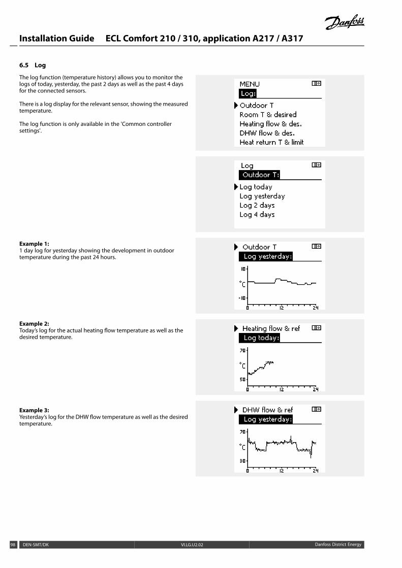
Installation Guide ECL Comfort 210 / 310, application A217 / A317
6.5 Log
The log function (temperature history) allows you to monitor thelogs of today, yesterday, the past 2 days as well as the past 4 daysfor the connected sensors.
There is a log display for the relevant sensor, showing themeasuredtemperature.
The log function is only available in the 'Common controllersettings'.
Example 1:1 day log for yesterday showing the development in outdoortemperature during the past 24 hours.
Example 2:Today’s log for the actual heating flow temperature as well as thedesired temperature.
Example 3:Yesterday’s log for the DHW flow temperature as well as the desiredtemperature.
98 DEN-SMT/DK VI.LG.U2.02 Danfoss District Energy
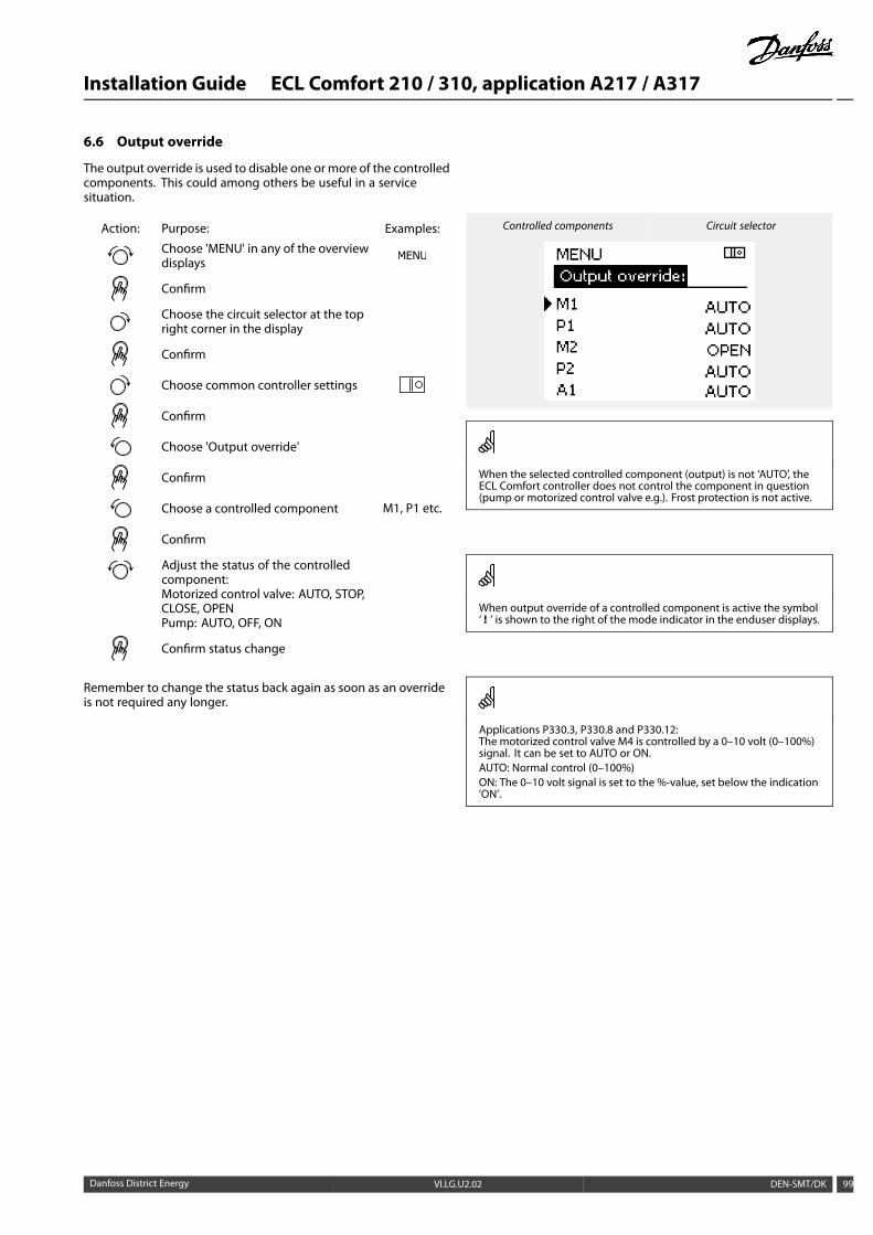
Installation Guide ECL Comfort 210 / 310, application A217 / A317
6.6 Output override
The output override is used to disable one ormore of the controlledcomponents. This could among others be useful in a servicesituation.
Action: Purpose: Examples:
Choose 'MENU' in any of the overviewdisplays
Confirm
Choose the circuit selector at the topright corner in the display
Confirm
Choose common controller settings
Confirm
Choose 'Output override'
Confirm
Choose a controlled component M1, P1 etc.
Confirm
Adjust the status of the controlledcomponent:Motorized control valve: AUTO, STOP,CLOSE, OPENPump: AUTO, OFF, ON
Confirm status change
Remember to change the status back again as soon as an overrideis not required any longer.
Controlled components Circuit selector
When the selected controlled component (output) is not ‘AUTO’, theECL Comfort controller does not control the component in question(pump or motorized control valve e.g.). Frost protection is not active.
When output override of a controlled component is active the symbol‘ ! ’ is shown to the right of the mode indicator in the enduser displays.
Applications P330.3, P330.8 and P330.12:The motorized control valve M4 is controlled by a 0–10 volt (0–100%)signal. It can be set to AUTO or ON.AUTO: Normal control (0–100%)ON: The 0–10 volt signal is set to the %-value, set below the indication'ON'.
Danfoss District Energy VI.LG.U2.02 DEN-SMT/DK 99
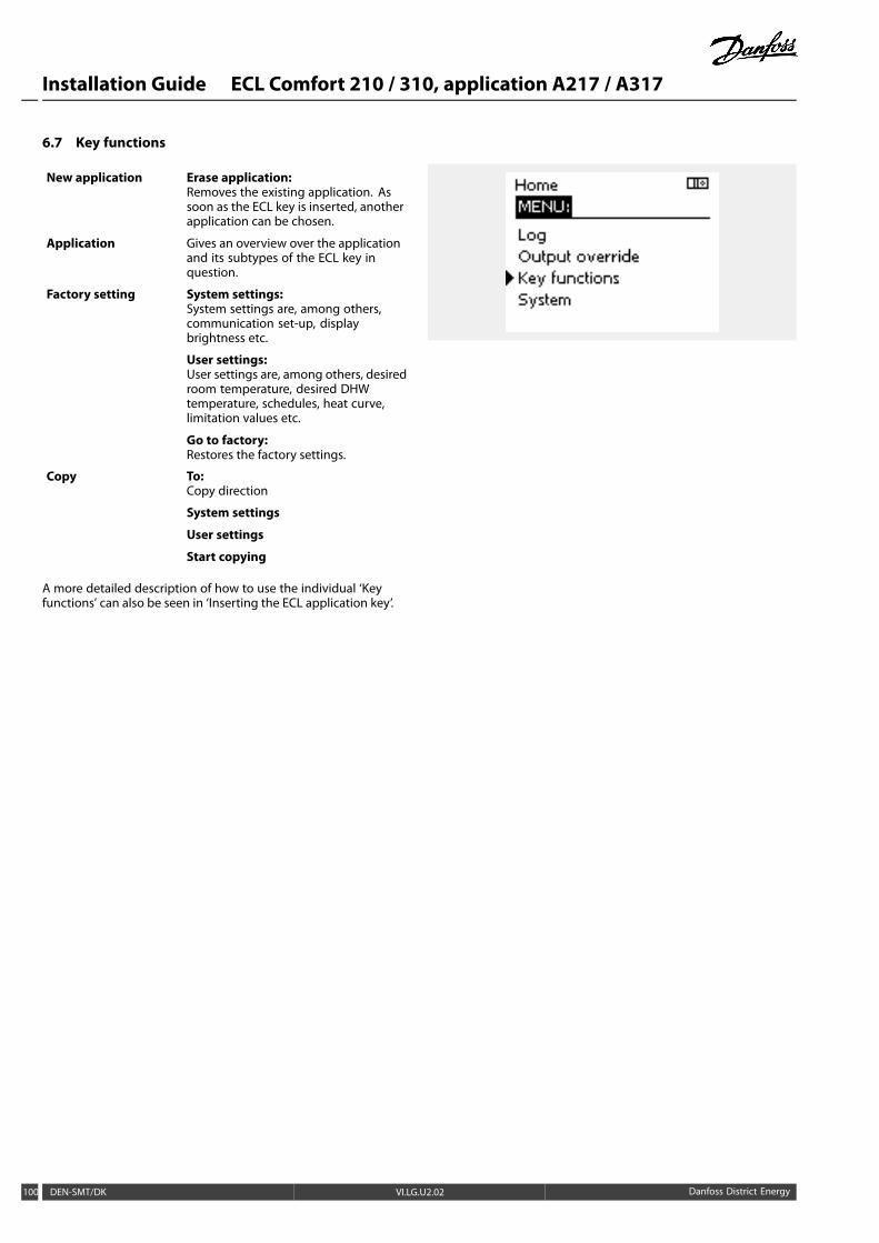
Installation Guide ECL Comfort 210 / 310, application A217 / A317
6.7 Key functions
New application Erase application:Removes the existing application. Assoon as the ECL key is inserted, anotherapplication can be chosen.
Application Gives an overview over the applicationand its subtypes of the ECL key inquestion.
Factory setting System settings:System settings are, among others,communication set-up, displaybrightness etc.
User settings:User settings are, among others, desiredroom temperature, desired DHWtemperature, schedules, heat curve,limitation values etc.
Go to factory:Restores the factory settings.
Copy To:Copy direction
System settings
User settings
Start copying
A more detailed description of how to use the individual ‘Keyfunctions’ can also be seen in ‘Inserting the ECL application key’.
100 DEN-SMT/DK VI.LG.U2.02 Danfoss District Energy
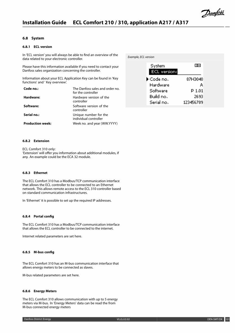
Installation Guide ECL Comfort 210 / 310, application A217 / A317
6.8 System
6.8.1 ECL version
In ‘ECL version’ you will always be able to find an overview of thedata related to your electronic controller.
Please have this information available if you need to contact yourDanfoss sales organization concerning the controller.
Information about your ECL Application Key can be found in ‘Keyfunctions’ and ‘ Key overview’.
Code no.: The Danfoss sales and order no.for the controller
Hardware: Hardware version of thecontroller
Software: Software version of thecontroller
Serial no.: Unique number for theindividual controller
Production week: Week no. and year (WW.YYYY)
Example, ECL version
6.8.2 Extension
ECL Comfort 310 only:‘Extension’ will offer you information about additional modules, ifany. An example could be the ECA 32 module.
6.8.3 Ethernet
The ECL Comfort 310 has a Modbus/TCP communication interfacethat allows the ECL controller to be connected to an Ethernetnetwork. This allows remote access to the ECL 310 controller basedon standard communication infrastructures.
In ‘Ethernet’ it is possible to set up the required IP addresses.
6.8.4 Portal config
The ECL Comfort 310 has a Modbus/TCP communication interfacethat allows the ECL controller to be connected to the internet.
Internet related parameters are set here.
6.8.5 M-bus config
The ECL Comfort 310 has an M-bus communication interface thatallows energy meters to be connected as slaves.
M-bus related parameters are set here.
6.8.6 Energy Meters
The ECL Comfort 310 allows communication with up to 5 energymeters via M-bus. In ‘Energy Meters’ data can be read the fromM-bus connected energy meters
Danfoss District Energy VI.LG.U2.02 DEN-SMT/DK 101
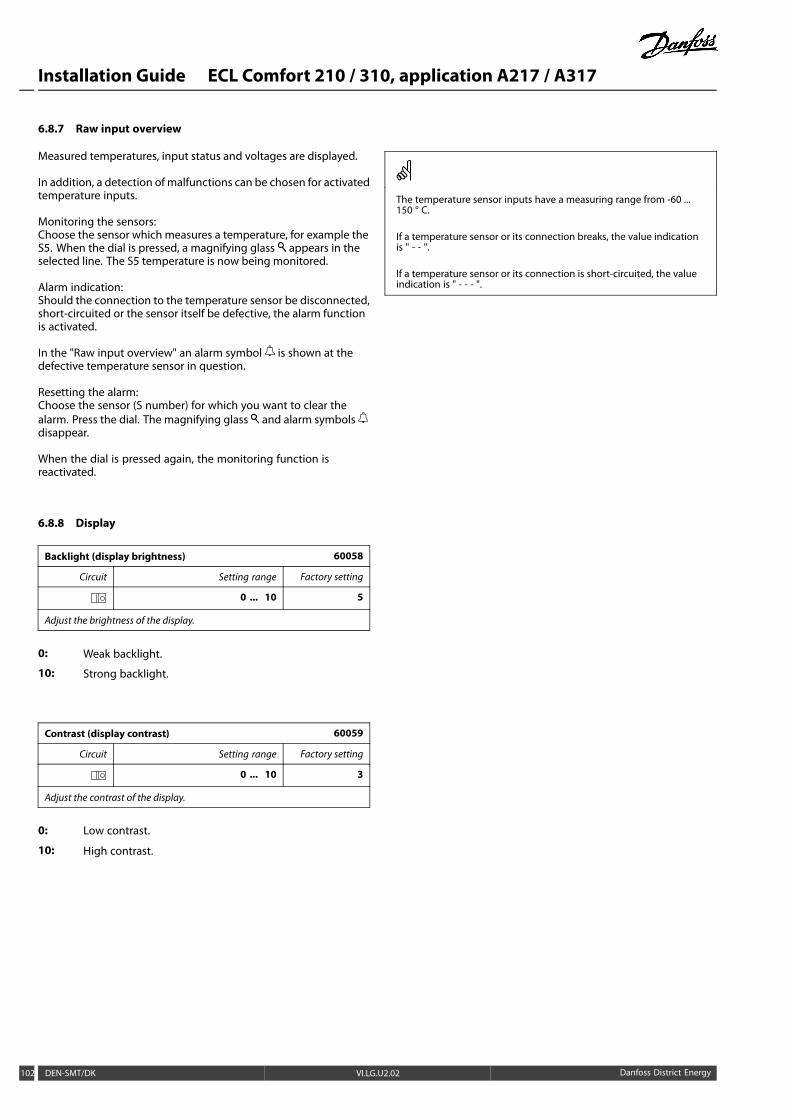
Installation Guide ECL Comfort 210 / 310, application A217 / A317
6.8.7 Raw input overview
Measured temperatures, input status and voltages are displayed.
In addition, a detection of malfunctions can be chosen for activatedtemperature inputs.
Monitoring the sensors:Choose the sensor which measures a temperature, for example theS5. When the dial is pressed, a magnifying glass appears in theselected line. The S5 temperature is now being monitored.
Alarm indication:Should the connection to the temperature sensor be disconnected,short-circuited or the sensor itself be defective, the alarm functionis activated.
In the "Raw input overview" an alarm symbol is shown at thedefective temperature sensor in question.
Resetting the alarm:Choose the sensor (S number) for which you want to clear thealarm. Press the dial. The magnifying glass and alarm symbolsdisappear.
When the dial is pressed again, the monitoring function isreactivated.
The temperature sensor inputs have a measuring range from -60 ...150 ° C.
If a temperature sensor or its connection breaks, the value indicationis " - - ".
If a temperature sensor or its connection is short-circuited, the valueindication is " - - - ".
6.8.8 Display
Backlight (display brightness) 60058
Circuit Setting range Factory setting
0 ... 10 5
Adjust the brightness of the display.
0: Weak backlight.
10: Strong backlight.
Contrast (display contrast) 60059
Circuit Setting range Factory setting
0 ... 10 3
Adjust the contrast of the display.
0: Low contrast.
10: High contrast.
102 DEN-SMT/DK VI.LG.U2.02 Danfoss District Energy

Installation Guide ECL Comfort 210 / 310, application A217 / A317
6.8.9 Communication
Modbus addr. 38
Circuit Setting range Factory setting
1 ... 247 1
Set the Modbus address if the controller is part of a Modbus network.
1 ... 247: Assign the Modbus address within the stated settingrange.
ECL 485 addr. (master / slave address) 2048
Circuit Setting range Factory setting
0 ... 15 15
This settting is relevant if more controllers are working in the same ECLComfort system (connected via the ECL 485 communication bus) and / orRemote Control Units (ECA 30 / 31) are connected.
0: The controller works as slave.The slave receives information about the outdoortemperature (S1), system time, and signal for DHWdemand in the master.
1 ... 9: The controller works as slave.The slave receives information about the outdoortemperature (S1), system time, and signal for DHWdemand in the master. The slave sends informationabout the desired flow temperature to the master.
10 ... 14: Reserved.
15: The ECL 485 communication bus is active.The controller is master. The master sends informationabout the outdoor temperature (S1) and system time.Connected Remote Control Units (ECA 30 / 31) arepowered.
The ECL Comfort controllers can be connected via the ECL 485communication bus to perform a larger system (the ECL 485communication bus can connect to max. 16 devices).
Each slave must be configured with its own address (1 ... 9).
However, more slaves can have the address 0 if they only have toreceive information about outdoor temperature and system time(listeners).
The total cable length of max. 200 m (all devices incl. the internal ECL485 communication bus) should not be exceeded.Cable lengths of more than 200 m may cause noise sensibility (EMC).
Service Pin 2150
Circuit Setting range Factory setting
0 / 1 0
This setting is only used in connection with set-up of Modbuscommunication.
Not applicable for the time being and reserved for future use!
Danfoss District Energy VI.LG.U2.02 DEN-SMT/DK 103
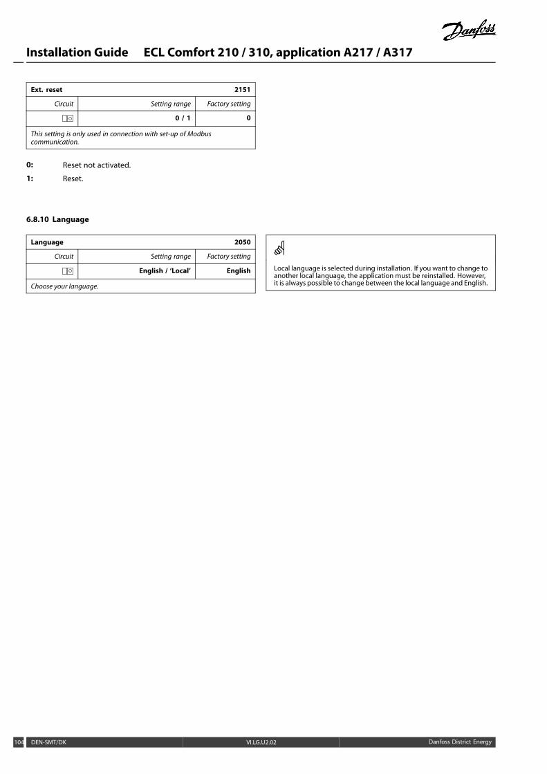
Installation Guide ECL Comfort 210 / 310, application A217 / A317
Ext. reset 2151
Circuit Setting range Factory setting
0 / 1 0
This setting is only used in connection with set-up of Modbuscommunication.
0: Reset not activated.
1: Reset.
6.8.10 Language
Language 2050
Circuit Setting range Factory setting
English / ‘Local’ English
Choose your language.
Local language is selected during installation. If you want to change toanother local language, the application must be reinstalled. However,it is always possible to change between the local language and English.
104 DEN-SMT/DK VI.LG.U2.02 Danfoss District Energy
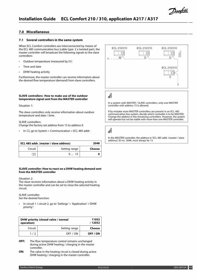
Installation Guide ECL Comfort 210 / 310, application A217 / A317
7.0 Miscellaneous
7.1 Several controllers in the same system
When ECL Comfort controllers are interconnected by means ofthe ECL 485 communication bus (cable type: 2 x twisted pair), themaster controller will broadcast the following signals to the slavecontrollers:
• Outdoor temperature (measured by S1)
• Time and date
• DHW heating activity
Furthermore, the master controller can receive information aboutthe desired flow temperature (demand) from slave controllers.
SLAVE controllers: How to make use of the outdoortemperature signal sent from the MASTER controller
Situation 1:
The slave controllers only receive information about outdoortemperature and date / time.
SLAVE controllers:Change the factory set address from 15 to address 0.
• In , go to System > Communication > ECL 485 addr:
ECL 485 addr. (master / slave address) 2048
Circuit Setting range Choose
0 ... 15 0
SLAVE controller: How to react on a DHWheating demand sentfrom the MASTER controller
Situation 2:The slave receives information about a DHW heating activity inthe master controller and can be set to close the selected heatingcircuit.
SLAVE controller:Set the desired function:
• In circuit 1 / circuit 2, go to ‘Settings’ > ‘Application’ >’DHWpriority’:
DHW priority (closed valve / normaloperation)
11052/ 12052
Circuit Setting range Choose
1 / 2 OFF / ON OFF / ON
OFF: The flow temperature control remains unchangedduring active DHW heating / charging in the mastercontroller.
ON: The valve in the heating circuit is closed during activeDHW heating / charging in the master controller.
In a system with MASTER / SLAVE controllers, only one MASTERcontroller with address 15 is allowed.
If by mistake more MASTER controllers are present in an ECL 485communication bus system, decide which controller is to be MASTER.Change the address in the remaining controllers. However, the systemwill operate but not be stable with more than one MASTER controller.
In the MASTER controller, the address in ‘ECL 485 addr. (master / slaveaddress)’, ID no. 2048, must always be 15.
Danfoss District Energy VI.LG.U2.02 DEN-SMT/DK 105
Installation Guide ECL Comfort 210 / 310, application A217 / A317
SLAVE controller: How tomake use of the outdoor temperaturesignal and send information about the desired flowtemperature back to the MASTER controller
Situation 3:
The slave controller receives information about outdoortemperature and date / time. The master controller receivesinformation about the desired flow temperature from slavecontrollers with an address from 1 ... 9:
SLAVE controller:
• In , go to System > Communication > ECL 485 addr.
• Change the factory set address from 15 to an address (1 ... 9).Each slave must be configured with its own address.
ECL 485 addr. (master / slave address) 2048
Circuit Setting range Choose
0 ... 15 1 ... 9
Furthermore, each slave can send information about the desiredflow temperature (demand) in each circuit back to the mastercontroller.
SLAVE controller:
• In the circuit in question, go to Settings > Application > Senddesired T
• Choose ON or OFF.
Send desired T 11500/ 12500
Circuit Setting range Choose
1 / 2 OFF / ON ON or OFF
OFF: Information about the desired flow temperature is notsent to the master controller.
ON: Information about the desired flow temperature is sentto the master controller.
MASTER controller:
• In the circuit 1, go to Settings > Application > Demand offset
• Change OFF to a value (for example 5 K) which is added to thehighest demand (desired flow temperature) from the slaves.
Demand offset 11017
Circuit Setting range Choose
1 OFF / 1 ... 20 K 1 ... 20 K
In the MASTER controller, the address in ‘ECL 485 addr. (master / slaveaddress)’, ID no. 2048, must always be 15.
106 DEN-SMT/DK VI.LG.U2.02 Danfoss District Energy
Installation Guide ECL Comfort 210 / 310, application A217 / A317
7.2 Frequently asked questions
The definitions apply to the Comfort 210 as well as ECL Comfort310 series. Consequently, you might come across expressionsthat are not mentioned in your guide.
The time shown in the display is one hour off?See ‘Time and Date’.
The time shown in the display is not correct?The internal clock may have been reset, if there has been a powerbreak for more than 72 hours.Go to the 'Common controller settings' and 'Time & Date' to setthe correct time.
The ECL Application Key is lost?Switch the power off and on again to see the system type and thesoftware generation of the controller or go to 'Common controllersettings' >'Key functions' > 'Application'. The system type (e.g.TYPE A266.1) and the system diagram is displayed.Order a replacement from your Danfoss representative (e.g. ECLApplication Key A266).Insert the new ECL Application Key and copy your personalsettings from the controller to the new ECL Application Key, ifrequired.
The room temperature is too low?Make sure that the radiator thermostat does not limit the roomtemperature.If you still cannot obtain the desired room temperature byadjusting the radiator thermostats, the flow temperature is toolow. Increase the desired room temperature (display with desiredroom temperature). If this does not help, adjust the ‘Heat curve’(‘Flow temp.’).
The room temperature is too high during saving periods?Make sure that the min. flow temperature limitation ('Temp. min.')is not too high.
The temperature is unstable?Check that the flow temperature sensor is correctly connectedand in the right place. Adjust the control parameters ('Controlpar.').If the controller has a room temperature signal, see 'Room limit'.
The controller does not operate and the control valve isclosed?Check that the flow temperature sensor is measuring the correctvalue, see 'Daily use' or 'Input overview'.Check the influence from other measured temperatures.
How tomake an extra comfort period in the schedule?You can set an additional comfort period by adding new ‘Start’and ‘Stop’ times in ‘Schedule’.
How to remove a comfort period in the schedule?You can remove a comfort period by setting start and stop timesto the same value.
How to restore your personal settings?Please read the chapter concerning ‘Inserting the ECL ApplicationKey’.
How to restore the factory settings?Please read the chapter concerning ‘Inserting the ECL ApplicationKey’.
Why can’t the settings be changed?The ECL Application Key has been removed.
Danfoss District Energy VI.LG.U2.02 DEN-SMT/DK 107

Installation Guide ECL Comfort 210 / 310, application A217 / A317
How to react on alarms?An alarm indicates that the system is not operating satisfactorily.Please contact your installer.
What does P and PI control mean?P control: Proportional control.By using a P control, the controller will change the flowtemperature proportional to the difference between a desiredand an actual temperature, e.g. a room temperature.A P control will always have an offset which not will disappearover time.
PI control: Proportional and Integrating control.A PI control does the same as a P control, but the offset willdisappear over time.A long ‘Tn’ will give a slow but stable control, and a short ‘Tn’ willresult in a fast control but with a higher risk of unstability.
108 DEN-SMT/DK VI.LG.U2.02 Danfoss District Energy
Installation Guide ECL Comfort 210 / 310, application A217 / A317
7.3 Definitions
The definitions apply to the Comfort 210 as well as ECL Comfort310 series. Consequently, you might come across expressionsthat are not mentioned in your guide.
Air duct temperatureTemperature measured in the air duct where the temperatureis to be controlled.
Alarm functionBased on the alarm settings, the controller can activate an output.
Anti-bacteria functionFor a defined period, the DHW temperature is increased in orderto neutralize dangerous bacteria, e.g. Legionella.
Balance temperatureThis setpoint is the basis for the flow / air duct temperature. Thebalance temperature can be adjusted by the room temperature,the compensation temperature and the return temperature. Thebalance temperature is only active if a room temperature sensoris connected.
Comfort operationNormal temperature in the system controlled by the schedule.During heating the flow temperature in the system is higher tomaintain the desired room temperature. During cooling the flowtemperature in the system is lower to maintain the desired roomtemperature.
Comfort temperatureTemperature maintained in the circuits during comfort periods.Normally during daytime.
Compensation temperatureA measured temperature influencing the flow temperaturereference / balance temperature.
Desired flow temperatureTemperature calculated by the controller on basis of the outdoortemperature and influences from the room and / or returntemperatures. This temperature is used as a reference for thecontrol.
Desired room temperatureTemperature which is set as the desired room temperature. Thetemperature can only be controlled by the ECL Comfort controllerif a room temperature sensor is installed.If a sensor is not installed, the set desired room temperaturehowever still influences the flow temperature.In both cases the room temperature in each room is typicallycontrolled by radiator thermostats / valves.
Desired temperatureTemperature based on a setting or a controller calculation.
Dew point temperatureTemperature at which the humidity in the air condensates.
DHW circuitThe circuit for heating the domestic hot water (DHW).
Factory settingsSettings stored on the ECL Application Key to simplify the set upof your controller the first time.
Flow temperatureTemperature measured in the flow at any time.
Danfoss District Energy VI.LG.U2.02 DEN-SMT/DK 109
Installation Guide ECL Comfort 210 / 310, application A217 / A317
Flow temperature referenceTemperature calculated by the controller on basis of the outdoortemperature and influences from the room and / or returntemperatures. This temperature is used as a reference for thecontrol.
Heat curveA curve showing the relationship between actual outdoortemperature and required flow temperature.
Heating circuitThe circuit for heating the room / building.
Holiday scheduleSelected days can be programmed to be in comfort, saving orfrost protection mode. Besides this, a day schedule with comfortperiod from 07.00 to 23.00 can be selected.
Humidity, relativeThis value (stated in %) refers to the indoor moisture contentcompared to the max. moisture content. The relative humidityis measured by the ECA 31 and is used for the calculation of thedew point temperature.
Limitation temperatureTemperature that influences the desired flow / balancetemperature.
Log functionThe temperature history is displayed.
Master / slaveTwo or more controllers are interconnected on the same bus,the master sends out e.g. time, date and outdoor temperature.The slave receives data from master and sends e.g. desired flowtemperature value.
Pt 1000 sensorAll sensors used with the ECL Comfort controller are based on thePt 1000 type (IEC 751B). The resistance is 1000 ohm at 0 °C and itchanges with 3.9 ohm / degree.
OptimizationThe controller optimizes the start time of the scheduledtemperature periods. Based on the outdoor temperature, thecontroller automatically calculates when to start in order to reachthe comfort temperature at the set time. The lower the outdoortemperature, the earlier the start time.
Outdoor temperature trendThe arrow indicates the tendency, i.e. whether the temperaturerises or falls.
Refill water functionIf the measured pressure in the heating system is too low (e.g.due to a leakage), water can be supplemented.
Return temperatureThe temperature measured in the return influences the desiredflow temperature.
Room temperature sensorTemperature sensor placed in the room (reference room, typicallythe living room) where the temperature is to be controlled.
Room temperatureTemperature measured by the room temperature sensor orthe Remote Control Unit. The room temperature can only becontrolled directly if a sensor is installed. The room temperatureinfluences the desired flow temperature.
ScheduleSchedule for periods with comfort and saving temperatures. Theschedule can be made individually for each week day and mayconsist of up to 3 comfort periods per day.
110 DEN-SMT/DK VI.LG.U2.02 Danfoss District Energy
Installation Guide ECL Comfort 210 / 310, application A217 / A317
Saving temperatureTemperature maintained in the heating / DHW circuit duringsaving temperature periods.
Pump controlOne circulation pump is working and the other is the sparecirculation pump. After a set time, the roles are exchanged.
Weather compensationFlow temperature control based on the outdoor temperature.The control is related to a user-defined heat curve.
2-point controlON / OFF control e.g. circulation pump, change-over valve ordamper control.
3-point controlOpening, closing or no action of the actuator for the motorizedcontrol valve. No action means that the actuator remains in itscurrent position.
Danfoss District Energy VI.LG.U2.02 DEN-SMT/DK 111
Installation Guide ECL Comfort 210 / 310, application A217 / A317
Installer:
By:
Date:
112 DEN-SMT/DK VI.LG.U2.02 Danfoss District Energy
Installation Guide ECL Comfort 210 / 310, application A217 / A317
*087H9038**VILGU202*
Produced by Danfoss A/S © 07/2012