Embed Size (px)
Citation preview
Installation Guide
FibeAir® IP-20E
Part ID: BM-0324-0 | DOC-00051205 Rev A.13
November 2017
© Copyright 2017 by Ceragon Networks Ltd. All rights reserved.

Installation Guide for FibeAir IP-20E
Page 2 of 84
Ceragon Proprietary and Confidential
Notice
This document contains information that is proprietary to Ceragon Networks Ltd. No part of this publication may be reproduced, modified, or distributed without prior written authorization of Ceragon Networks Ltd. This document is provided as is, without warranty of any kind.
Trademarks
Ceragon Networks®, FibeAir® and CeraView® are trademarks of Ceragon Networks Ltd., registered in the United States and other countries.
Ceragon® is a trademark of Ceragon Networks Ltd., registered in various countries.
CeraMap™, PolyView™, EncryptAir™, ConfigAir™, CeraMon™, EtherAir™, CeraBuild™, CeraWeb™, and QuickAir™, are trademarks of Ceragon Networks Ltd.
Other names mentioned in this publication are owned by their respective holders.
Statement of Conditions
The information contained in this document is subject to change without notice. Ceragon Networks Ltd. shall not be liable for errors contained herein or for incidental or consequential damage in connection with the furnishing, performance, or use of this document or equipment supplied with it.
Open Source Statement
The Product may use open source software, among them O/S software released under the GPL or GPL alike license ("Open Source License"). Inasmuch that such software is being used, it is released under the Open Source License, accordingly. The complete list of the software being used in this product including their respective license and the aforementioned public available changes is accessible at:
Network element site: ftp://ne-open-source.license-system.com
NMS site: ftp://nms-open-source.license-system.com/
Information to User
Any changes or modifications of equipment not expressly approved by the manufacturer could void the user’s authority to operate the equipment and the warranty for such equipment.
Intended Use/Limitation
Fixed point-to-point radio links for private networks.
Authorized to Use
Only entities with individual authorization from the National Regulator to operate the mentioned radio equipment.
The equipment can be used in the following EU countries:
Austria (AT) - Belgium (BE) - Bulgaria (BG) - Switzerland/Liechtenstein (CH) - Cyprus (CY) - Czech Republic (CZ) - Germany (DE) – Denmark (DK) - Estonia (EE) - Finland (FI) - France (FR) -Greece (GR) - Hungary (HU) - Ireland (IE) – Iceland (IS) – Italy (IT) – Lithuania (LT) - Luxembourg (LU) – Latvia (LV) - Malta (MT) - Netherlands (NL) - Norway (NO) - Portugal (PT) - Romania (RO) - Sweden (SE) - Slovenia (SI) - Slovak Republic (SK) – United Kingdom (UK) – Spain (SP) – Poland (PL)

Installation Guide for FibeAir IP-20E
Page 3 of 84
Ceragon Proprietary and Confidential
Table of Contents
1. Before You Start........................................................................................................ 8
1.1 Important Notes........................................................................................................................... 8
1.2 Safety Precautions & Declared Material ...................................................................................... 8 1.2.1 General Equipment Precautions .................................................................................................. 8 1.2.2 Précautions générales relatives à l'équipement .......................................................................... 9 1.2.3 Allgemeine Vorsichtsmaßnahmen für die Anlage ...................................................................... 10
1.3 Pre-Installation Instructions ....................................................................................................... 11 1.3.1 Packing ....................................................................................................................................... 11 1.3.2 Transportation and Storage ....................................................................................................... 11 1.3.3 Unpacking .................................................................................................................................. 11 1.3.4 Inspection .................................................................................................................................. 11
2. Product Hardware Description ................................................................................ 12
2.1 IP-20E Hardware Overview ........................................................................................................ 12 2.1.1 IP-20E Interfaces ........................................................................................................................ 13 2.1.2 IP-20E Interfaces – Variant A ..................................................................................................... 13 2.1.3 IP-20E Interfaces – Variant B ..................................................................................................... 14 2.1.4 Common IP-20E Interfaces ........................................................................................................ 15
2.2 PoE Injector ................................................................................................................................ 16 2.2.1 PoE Injector Interfaces ............................................................................................................... 16
2.3 Powering with External DC ........................................................................................................ 17
2.4 System Components .................................................................................................................. 18
2.5 Adaptors and Installation Kits .................................................................................................... 19
2.6 Antenna Connection .................................................................................................................. 19
2.7 Power Specifications .................................................................................................................. 20 2.7.1 Power Input Specifications ........................................................................................................ 20 2.7.2 Power Consumption Specifications ........................................................................................... 20 2.7.3 Power Connection Options ........................................................................................................ 20 2.7.4 PoE Injector Power Input ........................................................................................................... 20 2.7.5 Important Notes! ....................................................................................................................... 21
2.8 Environmental Specifications ..................................................................................................... 21
3. Cable Installation and Grounding ............................................................................. 22
3.1 Minimum and Maximum Cable Diameter ................................................................................. 22
3.2 Cable Grounding ........................................................................................................................ 22 3.2.1 Grounding Procedure ................................................................................................................. 23
3.3 Power Source ............................................................................................................................. 24
3.4 Surge Protection ........................................................................................................................ 24
3.5 Available Cable Options ............................................................................................................. 25 3.5.1 Fiber Optic Cables – Single Mode .............................................................................................. 25 3.5.2 Fiber Optic Cables – Multi Mode ............................................................................................... 26

Installation Guide for FibeAir IP-20E
Page 4 of 84
Ceragon Proprietary and Confidential
3.5.3 DC Cable and Connector ............................................................................................................ 27 3.5.4 Ethernet Cable and Specifications ............................................................................................. 27 3.5.5 Outdoor Ethernet Cable Specifications ...................................................................................... 28 3.5.6 Outdoor DC Cable Specifications ............................................................................................... 29
3.6 Securing the Cables .................................................................................................................... 30
3.7 Special Instructions for use of Glands ........................................................................................ 31 3.7.1 General Installation Procedure .................................................................................................. 32
3.8 Connecting an Optical Fiber Cable and SFP ............................................................................... 39 3.8.1 Types of SFPs .............................................................................................................................. 39 3.8.2 Connecting Optical Fiber to SFPs ............................................................................................... 40
3.9 Connecting a DC Power Cable .................................................................................................... 45
3.10 Connecting the Ethernet Cable .................................................................................................. 47 3.10.1 Preparing the Ethernet Cable and Plug-in Field ......................................................................... 47 3.10.2 Preparing the Ethernet Cable Already Assembled ..................................................................... 50 3.10.3 Connection of Ethernet Cable to IP-20E .................................................................................... 50 3.10.4 Connection of Extension Cable to IP-20E ................................................................................... 54
4. PoE Injector Installation and Connection ................................................................. 56
4.1 PoE Injector Cable Connection ................................................................................................... 56
4.2 PoE Injector Grounding .............................................................................................................. 57
4.3 PoE Injector Wall Mount Installation ......................................................................................... 57
4.4 PoE Injector Pole Mount Installation ......................................................................................... 59
4.5 PoE Injector 19” Rack Installation .............................................................................................. 60
4.6 PoE Injector ETSI Rack Installation ............................................................................................. 62
5. Generic Installation Procedures and Notes .............................................................. 64
5.1 Pole Mount Assembly and Installation ...................................................................................... 64
5.2 Performing Antenna Alignment Using the Integrated Antenna Pole Mount............................. 68 5.2.1 Adjusting the Antenna’s Azimuth .............................................................................................. 68 5.2.1 Adjusting the Antenna’s Elevation ............................................................................................. 69
6. IP-20E Detailed Configurations Description .............................................................. 70
6.1 1+0 Direct Mount Installation .................................................................................................... 70
6.2 1+0 with 43 dBi Flat Antenna ..................................................................................................... 74
6.3 2+0 Single Polarization ............................................................................................................... 79
6.4 2+0 Dual Polarization ................................................................................................................. 83

Installation Guide for FibeAir IP-20E
Page 5 of 84
Ceragon Proprietary and Confidential
List of Figures
Figure 1: IP-20E Rear View (Left) and Front View (Right) ....................................................... 12
Figure 2: Cable Gland Construction ........................................................................................ 12
Figure 3: IP-20E Interfaces – Variant A.................................................................................... 13
Figure 4: IP-20E Interfaces – Variant B .................................................................................... 14
Figure 5: RSL Interface............................................................................................................. 15
Figure 6: Grounding Screw ...................................................................................................... 15
Figure 7: PoE Injector .............................................................................................................. 16
Figure 8: PoE Injector Ports ..................................................................................................... 16
Figure 9: Two-Wire to PoE Port Power Adaptor ..................................................................... 17
Figure 10: IP-20E ..................................................................................................................... 18
Figure 11: Coupler/Splitter ...................................................................................................... 18
Figure 12: OMT ........................................................................................................................ 18
Figure 13: PoE Injector ............................................................................................................ 18
Figure 14: Twist for Coupler/Splitter ...................................................................................... 18
Figure 15: Cable Design ........................................................................................................... 27
Figure 16: Tightening the Front Portion of the Gland ............................................................. 37
Figure 17: Tightening the Rear Portion of the Gland .............................................................. 37
Figure 18: Mount Pole Mount to Pole .................................................................................... 67
Figure 19: Fine Elevation Adjustment ..................................................................................... 69
Figure 20: Horizontal / Vertical Pole ....................................................................................... 71
Figure 21: IP-20E Radio with 43 dBi Flat Antenna –Polarization Labels ................................. 75
Figure 22: V+45° Polarization .................................................................................................. 75
Figure 23: V-45° Polarization ................................................................................................... 75
Figure 24: V+45° Polarization (A on Top) ................................................................................ 77
Figure 25: V-45° Polarization (B on Top) ................................................................................. 77
Figure 26: Vertical Polarization ............................................................................................... 78
Figure 27: Complete Link – V-45° Polarization at Local Site (Left), V+45° Polarization at Remote Site (Right) ................................................................................................................. 78
Figure 28: Horizontal Polarization ........................................................................................... 80
Figure 29: Vertical Polarization ............................................................................................... 80

Installation Guide for FibeAir IP-20E
Page 6 of 84
Ceragon Proprietary and Confidential
List of Tables
Table 1: IP-20E Chassis Marketing Models ............................................................................. 13
Table 2: IP-20E Accessories ..................................................................................................... 19
Table 3: PoE Injector ............................................................................................................... 19
Table 4: Two-Wire to PoE Port Power Adaptor ...................................................................... 19
Table 5: Ethernet Cable Color Code ........................................................................................ 28
Table 6: Outdoor Ethernet Cable Electrical Requirements ..................................................... 28
Table 7: Outdoor Ethernet Cable Mechanical/Environmental Requirements ........................ 28
Table 8: Outdoor DC Cable Electrical Requirements............................................................... 29
Table 9: Outdoor DC Cable Mechanical/Environmental Requirements ................................. 29
Table 10: Cable Clamps ........................................................................................................... 30
Table 11: Glands Kit ................................................................................................................. 31
Table 12: Gland Cap ................................................................................................................ 31
Table 13: CSFP – SFP Compatibility Example .......................................................................... 39
Table 14: SFP Module Recommendations .............................................................................. 39
Table 15: CSFP Module Recommendations ............................................................................ 40
Table 16: SFP Module Recommendations for Third Party Equipment ................................... 40

Installation Guide for FibeAir IP-20E
Page 7 of 84
Ceragon Proprietary and Confidential
About This Guide
This guide describes the FibeAir IP-20E installation procedures and provides additional information concerning system parts and frequency bands.
What You Should Know
For the warranty to be honored, install the unit in accordance with the instructions in this manual.
Target Audience
This guide contains technical information about IP-20E installation, and is intended for use by qualified Ceragon technical personnel at all levels.
Related Documents
• FibeAir IP-20E Technical Description
• FibeAir IP-20C, IP-20S, and IP-20E User Guide
• FibeAir IP-20 Series MIB Reference

Installation Guide for FibeAir IP-20E
Page 8 of 84
Ceragon Proprietary and Confidential
1. Before You Start
1.1 Important Notes
• For the warranty to be honored, install the unit in accordance with the instructions in this manual.
• Any changes or modifications of equipment not expressly approved by the manufacturer could void the user’s authority to operate the equipment and the warranty for such equipment.
• IP-20E is intended for installation in a restricted access location.
• IP-20E must be installed and permanently connected to protective earth by qualified service personnel in accordance with applicable national electrical codes.
1.2 Safety Precautions & Declared Material
1.2.1 General Equipment Precautions
To avoid malfunctioning or personnel injuries, equipment or accessories/kits/plug-in unit installation, requires qualified and trained personnel. Changes or modifications not expressly approved by Ceragon Networks could void the user's authority to operate the equipment.
Where special cables, shields, adapters and grounding kits are supplied or described in this manual, these items must be used, to comply with the FCC regulations.
Use of controls, adjustments, or performing procedures other than those specified herein, may result in hazardous radiation exposure.
When working with an IP-20E, note the following risk of electric shock and energy hazard: Disconnecting one power supply disconnects only one power supply module. To isolate the unit completely, disconnect all power supplies.
Machine noise information order - 3. GPSGV, the highest sound pressure level amounts to 70 dB (A) or less, in accordance with ISO EN 7779.
Installation Guide for FibeAir IP-20E
Page 9 of 84
Ceragon Proprietary and Confidential
Static electricity may cause body harm, as well as harm to electronic components inside the device. Anyone responsible for the installation or maintenance of the IP-20E must use an ESD Wrist Strap. ESD protection measures must be observed when touching the unit. To prevent damage, before touching components inside the device, all electrostatic must be discharged from both personnel and tools.
In Norway and Sweden:
Equipment connected to the protective earthing of the building installation through the mains connection or through other equipment with a connection to protective earthing – and to a cable distribution system using coaxial cable, may in some circumstances create a fire hazard. Connection to a cable distribution system has therefore to be provided through a device providing electrical isolation below a certain frequency range (galvanic isolator, see EN 60728-11).
Utstyr som er koplet til beskyttelsesjord via nettplugg og/eller via annet jordtilkoplet utstyr – og er tilkoplet et kabel-TV nett, kan forårsake brannfare. For å unngå dette skal det ved tilkopling av utstyret til kabel-TV nettet installeres en galvanisk isolator mellom utstyret og kabel- TV nettet.
Utrustning som är kopplad till skyddsjord via jordat vägguttag och/eller via annan utrustning och samtidigt är kopplad till kabel-TV nät kan i vissa fall medfőra risk főr brand. Főr att undvika detta skall vid anslutning av utrustningen till kabel-TV nät galvanisk isolator finnas mellan utrustningen och kabel-TV nätet.
1.2.2 Précautions générales relatives à l'équipement
L’utilisation de commandes ou de réglages ou l'exécution de procédures autres que celles spécifiées dans les présentes peut engendrer une exposition dangereuse aux rayonnements.
L’usage de IP-20E s’accompagne du risque suivant d'électrocution et de danger électrique : le débranchement d'une alimentation électrique ne déconnecte qu'un module d'alimentation électrique. Pour isoler complètement l'unité, il faut débrancher toutes les alimentations électriques.
Bruit de machine d’ordre - 3. GPSGV, le plus haut niveau de pression sonore s'élève à 70 dB (A) au maximum, dans le respect de la norme ISO EN 7779.

Installation Guide for FibeAir IP-20E
Page 10 of 84
Ceragon Proprietary and Confidential
1.2.3 Allgemeine Vorsichtsmaßnahmen für die Anlage
Wenn andere Steuerelemente verwendet, Einstellungen vorgenommen oder Verfahren durchgeführt werden als die hier angegebenen, kann dies gefährliche Strahlung verursachen.
Beachten Sie beim Arbeiten mit IP-20E das folgende Stromschlag- und Gefahrenrisiko: Durch Abtrennen einer Stromquelle wird nur ein
Stromversorgungsmodul abgetrennt. Um die Einheit vollständig zu isolieren, trennen Sie alle Stromversorgungen ab.
Maschinenlärminformations-Verordnung - 3. GPSGV, der höchste Schalldruckpegel beträgt 70 dB(A) oder weniger gemäß EN ISO 7779.
Installation Guide for FibeAir IP-20E
Page 11 of 84
Ceragon Proprietary and Confidential
1.3 Pre-Installation Instructions
1.3.1 Packing
The equipment should be packed and sealed in moisture absorbing bags.
1.3.2 Transportation and Storage
The equipment cases are prepared for shipment by air, truck, railway and sea, suitable for handling by forklift trucks and slings. The cargo must be kept dry during transportation, in accordance with ETS 300 019-1-2, Class 2.3. For sea-transport, deck-side shipment is not permitted. Carrier-owned cargo containers should be used.
It is recommended that the equipment be transported to the installation site in its original packing case.
If intermediate storage is required, the packed equipment must be stored in a dry and cool environment, and out of direct sunlight, in accordance with ETS 300 019-1-1, Class 1.2.
1.3.3 Unpacking
The equipment is packed in sealed plastic bags and moisture absorbing bags are inserted. Any separate sensitive product, i.e. printed boards, are packed in anti-static handling bags. The equipment is further packed in special designed cases.
Marking is done according to standard practice unless otherwise specified by customers. The following details should be marked:
• Customers address
• Contract No
• Site name (if known)
• Case No
1.3.4 Inspection
Check the packing lists and ensure that correct parts numbers quantities of goods have arrived. Inspect for any damage on the cases and equipment. Report any damage or discrepancy to a Ceragon representative, by e-mail or fax.
Installation Guide for FibeAir IP-20E
Page 12 of 84
Ceragon Proprietary and Confidential
2. Product Hardware Description
2.1 IP-20E Hardware Overview
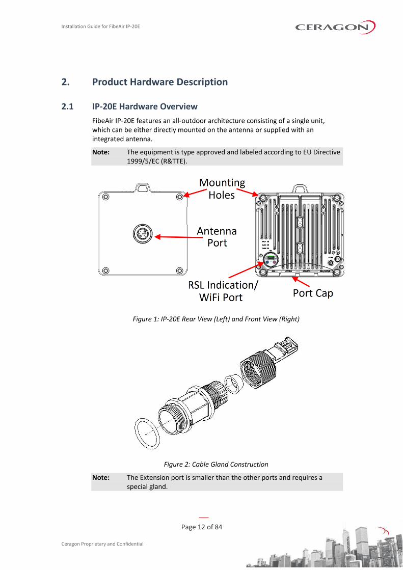
FibeAir IP-20E features an all-outdoor architecture consisting of a single unit, which can be either directly mounted on the antenna or supplied with an integrated antenna.
Note: The equipment is type approved and labeled according to EU Directive 1999/5/EC (R&TTE).
Figure 1: IP-20E Rear View (Left) and Front View (Right)
Figure 2: Cable Gland Construction
Note: The Extension port is smaller than the other ports and requires a special gland.
Installation Guide for FibeAir IP-20E
Page 13 of 84
Ceragon Proprietary and Confidential
2.1.1 IP-20E Interfaces
There are two variants of the IP-20E interface layout:
• Variant A – Two electrical Ethernet interfaces (Data Port 1 and Data Port 3) and one optical SFP cage that supports regular and CSFP standards (Data Port 2).
• Variant B – One electrical Ethernet interface (Data Port 1), an optical SFP cage that supports the regular SFP standard (Data Port 2), and an optical SFP cage that supports regular and CSFP standards (Data Port 3).
Note: Variant B requires CeraOS 9.0 or higher.
The following table provides the marketing models for the IP-20E unit options.
Table 1: IP-20E Chassis Marketing Models
Marketing Model Description
IP-20E-R2-DX0H-H-ESE Two electrical Ethernet ports, one SFP Ethernet port (high
power).
IP-20E-R2-DX0H-L-ESE Two electrical Ethernet ports, one SFP Ethernet port (standard
power).
IP-20E-R2-DX0H-H-ESS Two SFP Ethernet ports, one electrical Ethernet port (high
power).
IP-20E-R2-DX0H-L-ESS Two SFP Ethernet ports, one electrical Ethernet port (standard
power).
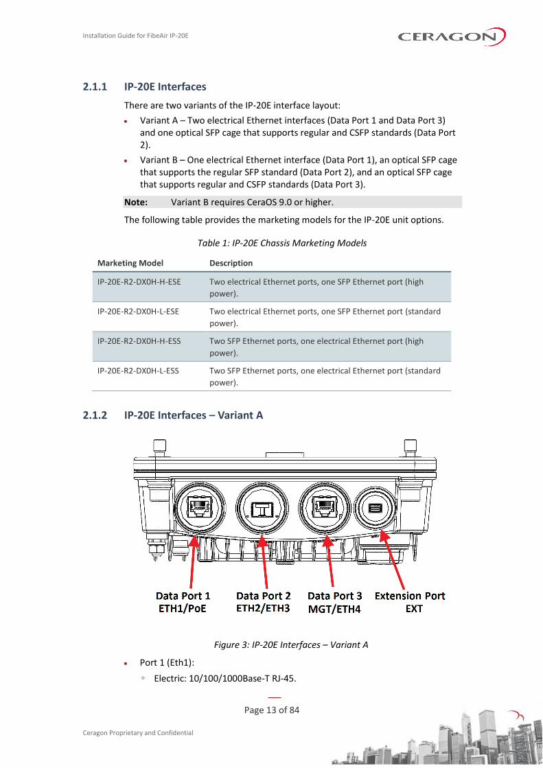
2.1.2 IP-20E Interfaces – Variant A
Figure 3: IP-20E Interfaces – Variant A
• Port 1 (Eth1):
◦ Electric: 10/100/1000Base-T RJ-45.
Installation Guide for FibeAir IP-20E
Page 14 of 84
Ceragon Proprietary and Confidential
◦ Proprietary PoE or external DC support (adapter)
• Port 2
◦ SFP cage which supports – Regular and CSFP standards
◦ Regular SFP provides Eth2
◦ CSFP (Dual BiDi SFP) provides Eth2 and Eth3.
• Port 3 (Eth4):
◦ Electric: 10/100/1000Base-T RJ-45.
◦ Eth traffic
◦ Default management port
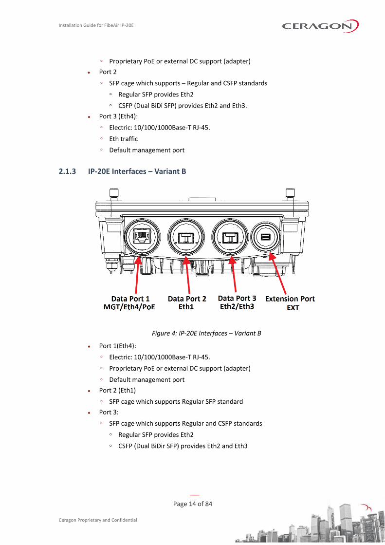
2.1.3 IP-20E Interfaces – Variant B
Figure 4: IP-20E Interfaces – Variant B
• Port 1(Eth4):
◦ Electric: 10/100/1000Base-T RJ-45.
◦ Proprietary PoE or external DC support (adapter)
◦ Default management port
• Port 2 (Eth1)
◦ SFP cage which supports Regular SFP standard
• Port 3:
◦ SFP cage which supports Regular and CSFP standards
◦ Regular SFP provides Eth2
◦ CSFP (Dual BiDir SFP) provides Eth2 and Eth3
Installation Guide for FibeAir IP-20E
Page 15 of 84
Ceragon Proprietary and Confidential
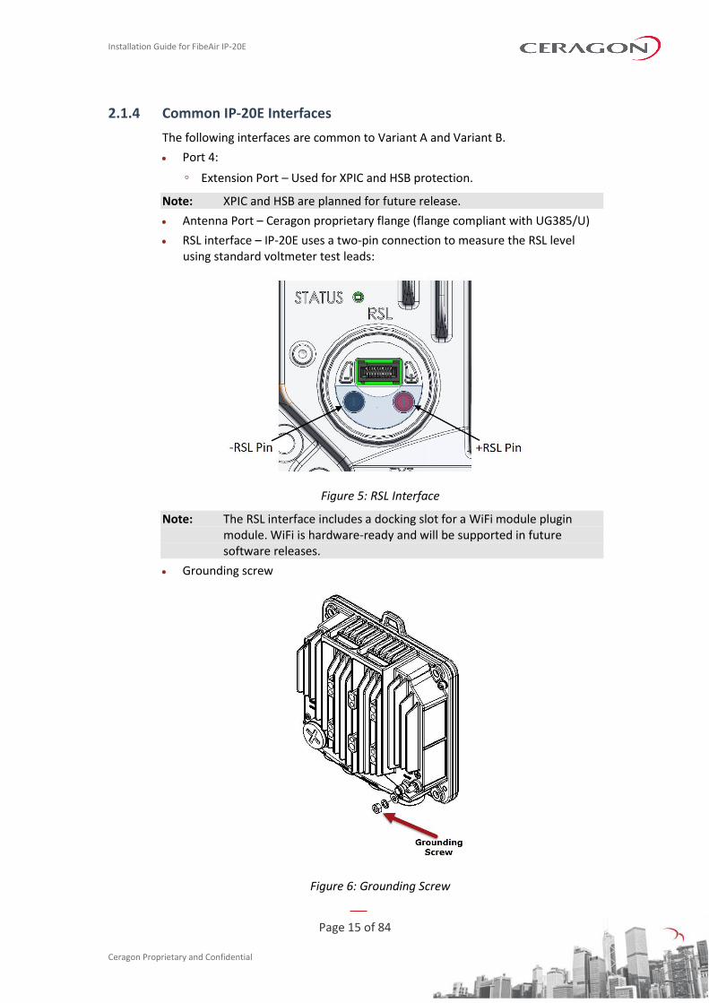
2.1.4 Common IP-20E Interfaces
The following interfaces are common to Variant A and Variant B.
• Port 4:
◦ Extension Port – Used for XPIC and HSB protection.
Note: XPIC and HSB are planned for future release.
• Antenna Port – Ceragon proprietary flange (flange compliant with UG385/U)
• RSL interface – IP-20E uses a two-pin connection to measure the RSL level using standard voltmeter test leads:
Figure 5: RSL Interface
Note: The RSL interface includes a docking slot for a WiFi module plugin module. WiFi is hardware-ready and will be supported in future software releases.
• Grounding screw
Figure 6: Grounding Screw
Installation Guide for FibeAir IP-20E
Page 16 of 84
Ceragon Proprietary and Confidential
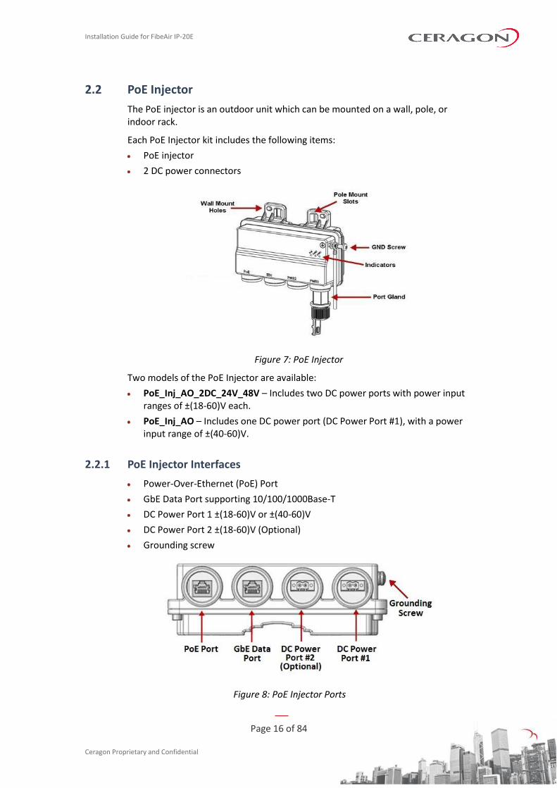
2.2 PoE Injector
The PoE injector is an outdoor unit which can be mounted on a wall, pole, or indoor rack.
Each PoE Injector kit includes the following items:
• PoE injector
• 2 DC power connectors
Figure 7: PoE Injector
Two models of the PoE Injector are available:
• PoE_Inj_AO_2DC_24V_48V – Includes two DC power ports with power input ranges of ±(18-60)V each.
• PoE_Inj_AO – Includes one DC power port (DC Power Port #1), with a power input range of ±(40-60)V.
2.2.1 PoE Injector Interfaces
• Power-Over-Ethernet (PoE) Port
• GbE Data Port supporting 10/100/1000Base-T
• DC Power Port 1 ±(18-60)V or ±(40-60)V
• DC Power Port 2 ±(18-60)V (Optional)
• Grounding screw
Figure 8: PoE Injector Ports
Installation Guide for FibeAir IP-20E
Page 17 of 84
Ceragon Proprietary and Confidential
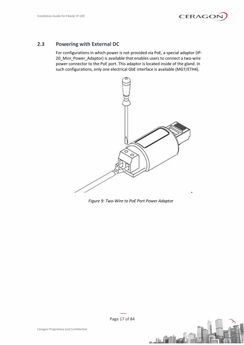
2.3 Powering with External DC
For configurations in which power is not provided via PoE, a special adaptor (IP-20_Mini_Power_Adaptor) is available that enables users to connect a two-wire power connector to the PoE port. This adaptor is located inside of the gland. In such configurations, only one electrical GbE interface is available (MGT/ETH4).
Figure 9: Two-Wire to PoE Port Power Adaptor
Installation Guide for FibeAir IP-20E
Page 18 of 84
Ceragon Proprietary and Confidential
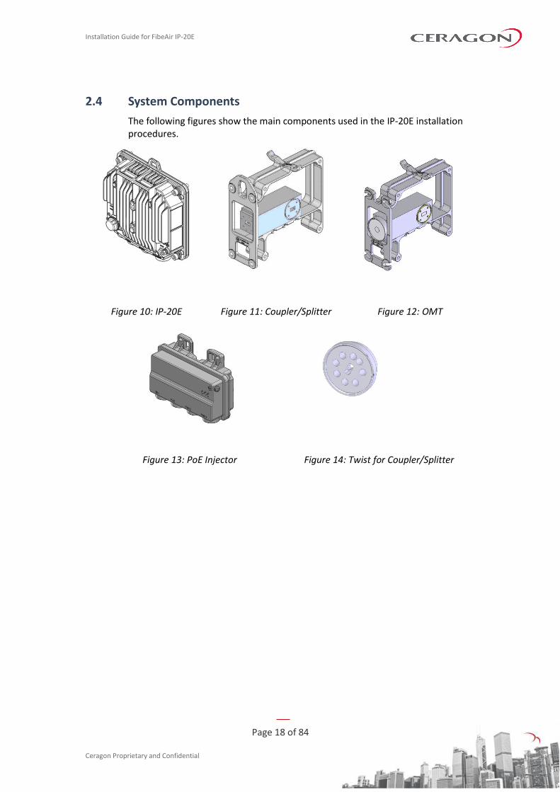
2.4 System Components
The following figures show the main components used in the IP-20E installation procedures.
Figure 10: IP-20E Figure 11: Coupler/Splitter Figure 12: OMT
Figure 13: PoE Injector Figure 14: Twist for Coupler/Splitter
Installation Guide for FibeAir IP-20E
Page 19 of 84
Ceragon Proprietary and Confidential
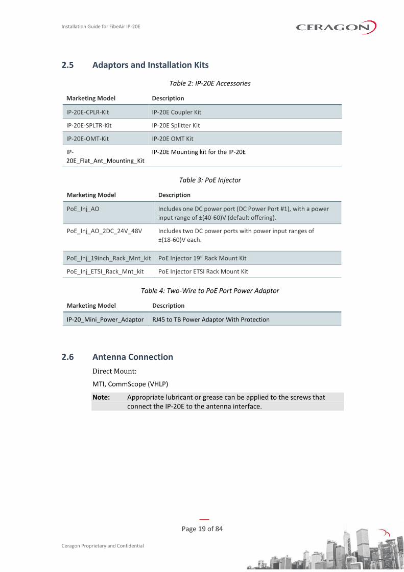
2.5 Adaptors and Installation Kits
Table 2: IP-20E Accessories
Marketing Model Description
IP-20E-CPLR-Kit IP-20E Coupler Kit
IP-20E-SPLTR-Kit IP-20E Splitter Kit
IP-20E-OMT-Kit IP-20E OMT Kit
IP-
20E_Flat_Ant_Mounting_Kit
IP-20E Mounting kit for the IP-20E
Table 3: PoE Injector
Marketing Model Description
PoE_Inj_AO Includes one DC power port (DC Power Port #1), with a power
input range of ±(40-60)V (default offering).
PoE_Inj_AO_2DC_24V_48V Includes two DC power ports with power input ranges of
±(18-60)V each.
PoE_Inj_19inch_Rack_Mnt_kit PoE Injector 19” Rack Mount Kit
PoE_Inj_ETSI_Rack_Mnt_kit PoE Injector ETSI Rack Mount Kit
Table 4: Two-Wire to PoE Port Power Adaptor
Marketing Model Description
IP-20_Mini_Power_Adaptor RJ45 to TB Power Adaptor With Protection
2.6 Antenna Connection
Direct Mount:
MTI, CommScope (VHLP)
Note: Appropriate lubricant or grease can be applied to the screws that connect the IP-20E to the antenna interface.
Installation Guide for FibeAir IP-20E
Page 20 of 84
Ceragon Proprietary and Confidential
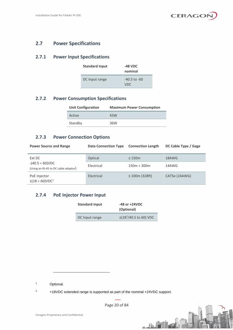
2.7 Power Specifications
2.7.1 Power Input Specifications
Standard Input -48 VDC
nominal
DC Input range -40.5 to -60
VDC
2.7.2 Power Consumption Specifications
Unit Configuration Maximum Power Consumption
Active 43W
Standby 36W
2.7.3 Power Connection Options
Power Source and Range Data Connection Type Connection Length DC Cable Type / Gage
Ext DC
-(40.5 ÷ 60)VDC
(Using an RJ-45 to DC cable adaptor)
Optical ≤ 150m 18AWG
Electrical 150m ÷ 300m 14AWG
PoE Injector
±(18 ÷ 60)VDC1 Electrical ≤ 100m (328ft) CAT5e (24AWG)
2.7.4 PoE Injector Power Input
Standard Input -48 or +24VDC
(Optional)
DC Input range ±(182/40.5 to 60) VDC
1 Optional.
2 +18VDC extended range is supported as part of the nominal +24VDC support.

Installation Guide for FibeAir IP-20E
Page 21 of 84
Ceragon Proprietary and Confidential
2.7.5 Important Notes!
• The unit must only be installed by service personnel.
• The unit must have a permanent connection to protective grounding.
• Data port 2 (ETH2/ETH3) does not provide protection from over-voltages on telecommunication networks for host equipment users.
• The RSL interface connector is intended for technician use only.
• Disconnect device (circuit breaker) in the building installation:
• Shall be readily accessible and incorporated external to the equipment.
• The maximum rating of the overcurrent protection shall be up to 6 Amp.
2.8 Environmental Specifications
Operating: ETSI EN 300 019-1-4 Class 4.1
Temperature range for continuous operating temperature with high reliability: -33°C (-27°F) to +55°C (131°F)
Temperature range for exceptional temperatures; tested successfully, with limited margins: -45°C (-49°F) to +60°C (140°F)
Humidity: 5%RH to 100%RH IEC529 IP66
Storage: ETSI EN 300 019-1-1 Class 1.2
Transportation: ETSI EN 300 019-1-2 Class 2.3
Installation Guide for FibeAir IP-20E
Page 22 of 84
Ceragon Proprietary and Confidential
3. Cable Installation and Grounding
3.1 Minimum and Maximum Cable Diameter
To fit the gland, the outer cable diameter should be between 6-10 mm. This applies to all glands on both the IP-20E unit and the PoE Injector.
To fit the grounding clamp, the outer diameter of CAT5E Ethernet cables must be between 6-7.1mm.
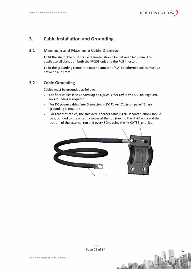
3.2 Cable Grounding
Cables must be grounded as follows:
• For fiber cables (see Connecting an Optical Fiber Cable and SFP on page 39), no grounding is required.
• For DC power cables (see Connecting a DC Power Cable on page 45), no grounding is required.
• For Ethernet cables, the shielded Ethernet cable (SF/UTP construction) should be grounded to the antenna tower at the top (next to the IP-20 unit) and the bottom of the external run and every 50m, using the kit CAT5E_gnd_kit.
Installation Guide for FibeAir IP-20E
Page 23 of 84
Ceragon Proprietary and Confidential
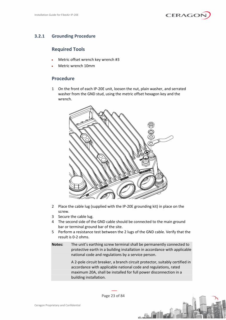
3.2.1 Grounding Procedure
Required Tools
• Metric offset wrench key wrench #3
• Metric wrench 10mm
Procedure
1 On the front of each IP-20E unit, loosen the nut, plain washer, and serrated washer from the GND stud, using the metric offset hexagon key and the wrench.
2 Place the cable lug (supplied with the IP-20E grounding kit) in place on the screw.
3 Secure the cable lug. 4 The second side of the GND cable should be connected to the main ground
bar or terminal ground bar of the site. 5 Perform a resistance test between the 2 lugs of the GND cable. Verify that the
result is 0-2 ohms.
Notes: The unit’s earthing screw terminal shall be permanently connected to protective earth in a building installation in accordance with applicable national code and regulations by a service person.
A 2-pole circuit breaker, a branch circuit protector, suitably certified in accordance with applicable national code and regulations, rated maximum 20A, shall be installed for full power disconnection in a building installation.

Installation Guide for FibeAir IP-20E
Page 24 of 84
Ceragon Proprietary and Confidential
Any outdoor antenna cable shield shall be permanently connected to protective earth in a building installation.
3.3 Power Source
The power cable must be plugged into the unit before turning on the external power.
When selecting a power source, the following must be considered:
Recommended: Availability of a UPS (Uninterrupted Power Source), battery backup, and emergency power generator.
The power supply must have grounding points on the AC and DC sides.
Caution! The user power supply GND must be connected to the positive pole in the IP-20E power supply. Any other connection may cause damage to the system!
Note! For the warranty to be honored, you must install the IP-20E in accordance with the instructions above.
3.4 Surge Protection
IP-20E includes built-in surge protection for its Ethernet and power interfaces. IP-20E’s surge protection implementation complies with surge immunity standard IEC 61000-4-5, level 4, provided the Ethernet cables were prepared according to the instructions in Connecting the Ethernet Cable on page 47.
In areas in which severe lighting conditions are likely to occur, it is strongly recommended to add additional protection by placing lightning protectors on all electrical Ethernet cables, near the connection points with the IP-20E unit.
Installation Guide for FibeAir IP-20E
Page 25 of 84
Ceragon Proprietary and Confidential
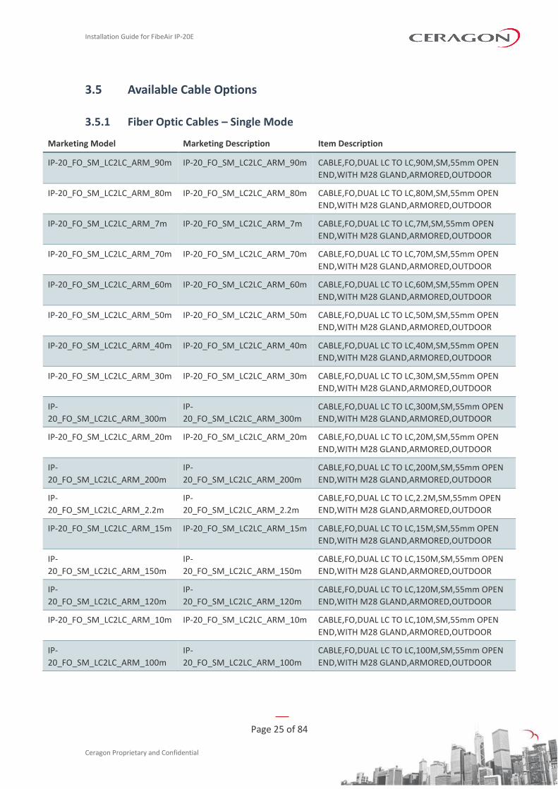
3.5 Available Cable Options
3.5.1 Fiber Optic Cables – Single Mode
Marketing Model Marketing Description Item Description
IP-20_FO_SM_LC2LC_ARM_90m IP-20_FO_SM_LC2LC_ARM_90m CABLE,FO,DUAL LC TO LC,90M,SM,55mm OPEN
END,WITH M28 GLAND,ARMORED,OUTDOOR
IP-20_FO_SM_LC2LC_ARM_80m IP-20_FO_SM_LC2LC_ARM_80m CABLE,FO,DUAL LC TO LC,80M,SM,55mm OPEN
END,WITH M28 GLAND,ARMORED,OUTDOOR
IP-20_FO_SM_LC2LC_ARM_7m IP-20_FO_SM_LC2LC_ARM_7m CABLE,FO,DUAL LC TO LC,7M,SM,55mm OPEN
END,WITH M28 GLAND,ARMORED,OUTDOOR
IP-20_FO_SM_LC2LC_ARM_70m IP-20_FO_SM_LC2LC_ARM_70m CABLE,FO,DUAL LC TO LC,70M,SM,55mm OPEN
END,WITH M28 GLAND,ARMORED,OUTDOOR
IP-20_FO_SM_LC2LC_ARM_60m IP-20_FO_SM_LC2LC_ARM_60m CABLE,FO,DUAL LC TO LC,60M,SM,55mm OPEN
END,WITH M28 GLAND,ARMORED,OUTDOOR
IP-20_FO_SM_LC2LC_ARM_50m IP-20_FO_SM_LC2LC_ARM_50m CABLE,FO,DUAL LC TO LC,50M,SM,55mm OPEN
END,WITH M28 GLAND,ARMORED,OUTDOOR
IP-20_FO_SM_LC2LC_ARM_40m IP-20_FO_SM_LC2LC_ARM_40m CABLE,FO,DUAL LC TO LC,40M,SM,55mm OPEN
END,WITH M28 GLAND,ARMORED,OUTDOOR
IP-20_FO_SM_LC2LC_ARM_30m IP-20_FO_SM_LC2LC_ARM_30m CABLE,FO,DUAL LC TO LC,30M,SM,55mm OPEN
END,WITH M28 GLAND,ARMORED,OUTDOOR
IP-
20_FO_SM_LC2LC_ARM_300m
IP-
20_FO_SM_LC2LC_ARM_300m
CABLE,FO,DUAL LC TO LC,300M,SM,55mm OPEN
END,WITH M28 GLAND,ARMORED,OUTDOOR
IP-20_FO_SM_LC2LC_ARM_20m IP-20_FO_SM_LC2LC_ARM_20m CABLE,FO,DUAL LC TO LC,20M,SM,55mm OPEN
END,WITH M28 GLAND,ARMORED,OUTDOOR
IP-
20_FO_SM_LC2LC_ARM_200m
IP-
20_FO_SM_LC2LC_ARM_200m
CABLE,FO,DUAL LC TO LC,200M,SM,55mm OPEN
END,WITH M28 GLAND,ARMORED,OUTDOOR
IP-
20_FO_SM_LC2LC_ARM_2.2m
IP-
20_FO_SM_LC2LC_ARM_2.2m
CABLE,FO,DUAL LC TO LC,2.2M,SM,55mm OPEN
END,WITH M28 GLAND,ARMORED,OUTDOOR
IP-20_FO_SM_LC2LC_ARM_15m IP-20_FO_SM_LC2LC_ARM_15m CABLE,FO,DUAL LC TO LC,15M,SM,55mm OPEN
END,WITH M28 GLAND,ARMORED,OUTDOOR
IP-
20_FO_SM_LC2LC_ARM_150m
IP-
20_FO_SM_LC2LC_ARM_150m
CABLE,FO,DUAL LC TO LC,150M,SM,55mm OPEN
END,WITH M28 GLAND,ARMORED,OUTDOOR
IP-
20_FO_SM_LC2LC_ARM_120m
IP-
20_FO_SM_LC2LC_ARM_120m
CABLE,FO,DUAL LC TO LC,120M,SM,55mm OPEN
END,WITH M28 GLAND,ARMORED,OUTDOOR
IP-20_FO_SM_LC2LC_ARM_10m IP-20_FO_SM_LC2LC_ARM_10m CABLE,FO,DUAL LC TO LC,10M,SM,55mm OPEN
END,WITH M28 GLAND,ARMORED,OUTDOOR
IP-
20_FO_SM_LC2LC_ARM_100m
IP-
20_FO_SM_LC2LC_ARM_100m
CABLE,FO,DUAL LC TO LC,100M,SM,55mm OPEN
END,WITH M28 GLAND,ARMORED,OUTDOOR
Installation Guide for FibeAir IP-20E
Page 26 of 84
Ceragon Proprietary and Confidential
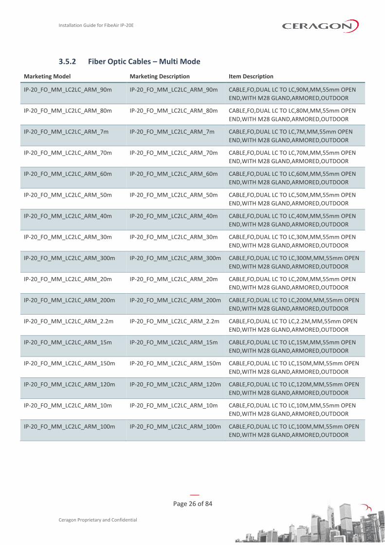
3.5.2 Fiber Optic Cables – Multi Mode
Marketing Model Marketing Description Item Description
IP-20_FO_MM_LC2LC_ARM_90m IP-20_FO_MM_LC2LC_ARM_90m CABLE,FO,DUAL LC TO LC,90M,MM,55mm OPEN
END,WITH M28 GLAND,ARMORED,OUTDOOR
IP-20_FO_MM_LC2LC_ARM_80m IP-20_FO_MM_LC2LC_ARM_80m CABLE,FO,DUAL LC TO LC,80M,MM,55mm OPEN
END,WITH M28 GLAND,ARMORED,OUTDOOR
IP-20_FO_MM_LC2LC_ARM_7m IP-20_FO_MM_LC2LC_ARM_7m CABLE,FO,DUAL LC TO LC,7M,MM,55mm OPEN
END,WITH M28 GLAND,ARMORED,OUTDOOR
IP-20_FO_MM_LC2LC_ARM_70m IP-20_FO_MM_LC2LC_ARM_70m CABLE,FO,DUAL LC TO LC,70M,MM,55mm OPEN
END,WITH M28 GLAND,ARMORED,OUTDOOR
IP-20_FO_MM_LC2LC_ARM_60m IP-20_FO_MM_LC2LC_ARM_60m CABLE,FO,DUAL LC TO LC,60M,MM,55mm OPEN
END,WITH M28 GLAND,ARMORED,OUTDOOR
IP-20_FO_MM_LC2LC_ARM_50m IP-20_FO_MM_LC2LC_ARM_50m CABLE,FO,DUAL LC TO LC,50M,MM,55mm OPEN
END,WITH M28 GLAND,ARMORED,OUTDOOR
IP-20_FO_MM_LC2LC_ARM_40m IP-20_FO_MM_LC2LC_ARM_40m CABLE,FO,DUAL LC TO LC,40M,MM,55mm OPEN
END,WITH M28 GLAND,ARMORED,OUTDOOR
IP-20_FO_MM_LC2LC_ARM_30m IP-20_FO_MM_LC2LC_ARM_30m CABLE,FO,DUAL LC TO LC,30M,MM,55mm OPEN
END,WITH M28 GLAND,ARMORED,OUTDOOR
IP-20_FO_MM_LC2LC_ARM_300m IP-20_FO_MM_LC2LC_ARM_300m CABLE,FO,DUAL LC TO LC,300M,MM,55mm OPEN
END,WITH M28 GLAND,ARMORED,OUTDOOR
IP-20_FO_MM_LC2LC_ARM_20m IP-20_FO_MM_LC2LC_ARM_20m CABLE,FO,DUAL LC TO LC,20M,MM,55mm OPEN
END,WITH M28 GLAND,ARMORED,OUTDOOR
IP-20_FO_MM_LC2LC_ARM_200m IP-20_FO_MM_LC2LC_ARM_200m CABLE,FO,DUAL LC TO LC,200M,MM,55mm OPEN
END,WITH M28 GLAND,ARMORED,OUTDOOR
IP-20_FO_MM_LC2LC_ARM_2.2m IP-20_FO_MM_LC2LC_ARM_2.2m CABLE,FO,DUAL LC TO LC,2.2M,MM,55mm OPEN
END,WITH M28 GLAND,ARMORED,OUTDOOR
IP-20_FO_MM_LC2LC_ARM_15m IP-20_FO_MM_LC2LC_ARM_15m CABLE,FO,DUAL LC TO LC,15M,MM,55mm OPEN
END,WITH M28 GLAND,ARMORED,OUTDOOR
IP-20_FO_MM_LC2LC_ARM_150m IP-20_FO_MM_LC2LC_ARM_150m CABLE,FO,DUAL LC TO LC,150M,MM,55mm OPEN
END,WITH M28 GLAND,ARMORED,OUTDOOR
IP-20_FO_MM_LC2LC_ARM_120m IP-20_FO_MM_LC2LC_ARM_120m CABLE,FO,DUAL LC TO LC,120M,MM,55mm OPEN
END,WITH M28 GLAND,ARMORED,OUTDOOR
IP-20_FO_MM_LC2LC_ARM_10m IP-20_FO_MM_LC2LC_ARM_10m CABLE,FO,DUAL LC TO LC,10M,MM,55mm OPEN
END,WITH M28 GLAND,ARMORED,OUTDOOR
IP-20_FO_MM_LC2LC_ARM_100m IP-20_FO_MM_LC2LC_ARM_100m CABLE,FO,DUAL LC TO LC,100M,MM,55mm OPEN
END,WITH M28 GLAND,ARMORED,OUTDOOR
Installation Guide for FibeAir IP-20E
Page 27 of 84
Ceragon Proprietary and Confidential
3.5.3 DC Cable and Connector
Marketing P/N Description
Outdoor_DC_cbl_2x18AWG_drum CABLE,305M,OUTDOOR_DC_CBL_2X18AWG_DRUM
IP-20_Mini_Power_Adaptor IP-20 Mini Power Adaptor
3.5.4 Ethernet Cable and Specifications
Marketing P/N Description
CAT5E_SFUTP_Outdoor_305m_drum CABLE,MATERIAL,CAT-5E,SFUTP,4X2X24AWG,UV
RESISTANCE,305M
This cable has the following specifications:
• Suitable for:
◦ Fast Ethernet
◦ Gigabit Ethernet
◦ PoE
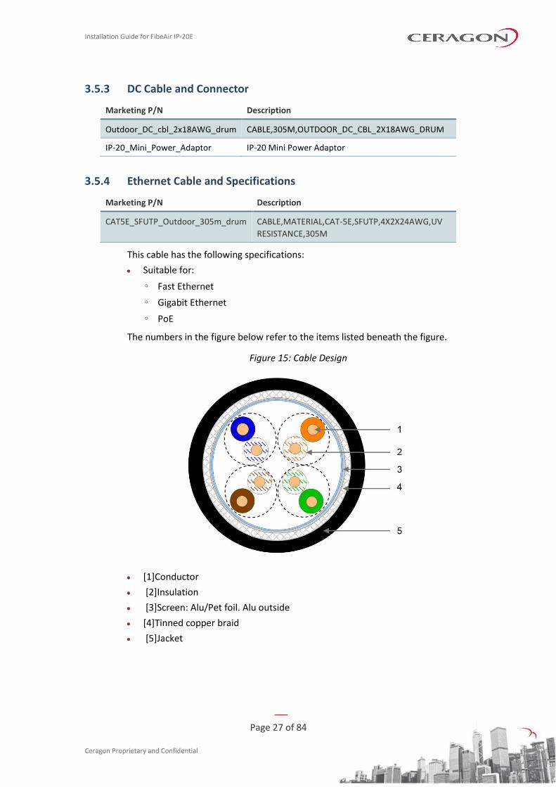
The numbers in the figure below refer to the items listed beneath the figure.
Figure 15: Cable Design
• [1]Conductor
• [2]Insulation
• [3]Screen: Alu/Pet foil. Alu outside
• [4]Tinned copper braid
• [5]Jacket
Installation Guide for FibeAir IP-20E
Page 28 of 84
Ceragon Proprietary and Confidential
Table 5: Ethernet Cable Color Code
Pair Wire A Wire B
1 WHITE-blue BLUE
2 WHITE-orange ORANGE
3 WHITE-green GREEN
4 WHITE-brown BROWN
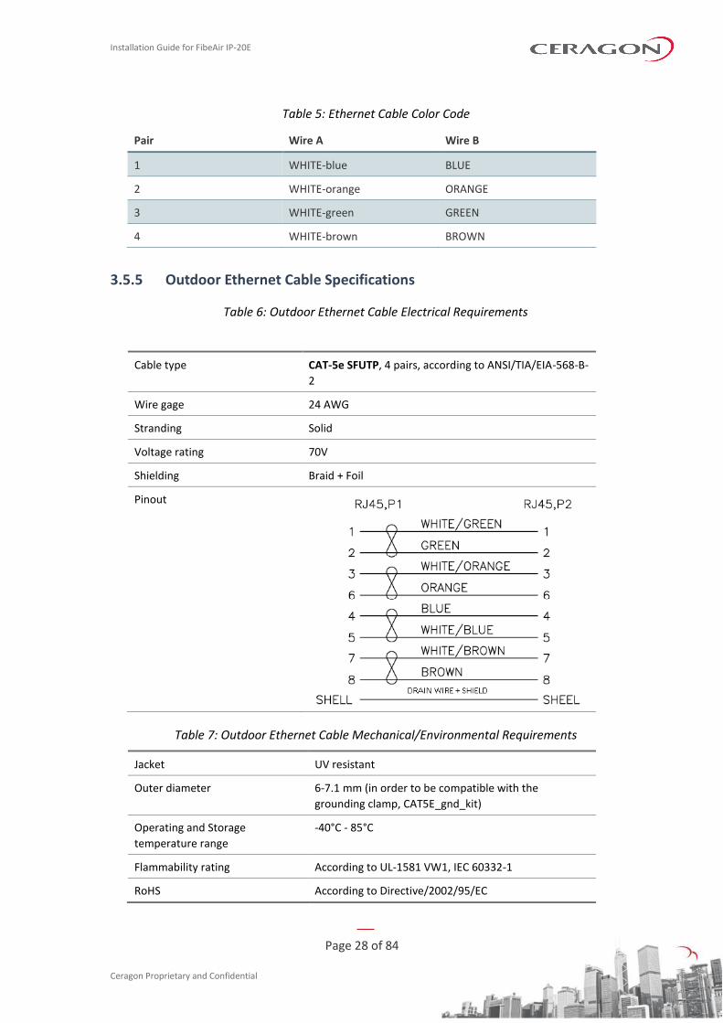
3.5.5 Outdoor Ethernet Cable Specifications
Table 6: Outdoor Ethernet Cable Electrical Requirements
Cable type CAT-5e SFUTP, 4 pairs, according to ANSI/TIA/EIA-568-B-
2
Wire gage 24 AWG
Stranding Solid
Voltage rating 70V
Shielding Braid + Foil
Pinout
Table 7: Outdoor Ethernet Cable Mechanical/Environmental Requirements
Jacket UV resistant
Outer diameter 6-7.1 mm (in order to be compatible with the
grounding clamp, CAT5E_gnd_kit)
Operating and Storage
temperature range
-40°C - 85°C
Flammability rating According to UL-1581 VW1, IEC 60332-1
RoHS According to Directive/2002/95/EC
Installation Guide for FibeAir IP-20E
Page 29 of 84
Ceragon Proprietary and Confidential
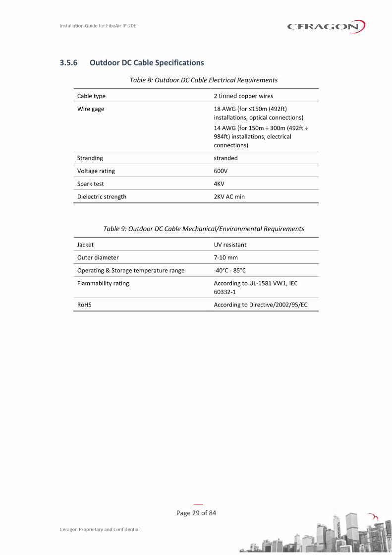
3.5.6 Outdoor DC Cable Specifications
Table 8: Outdoor DC Cable Electrical Requirements
Cable type 2 tinned copper wires
Wire gage 18 AWG (for ≤150m (492ft)
installations, optical connections)
14 AWG (for 150m ÷ 300m (492ft ÷
984ft) installations, electrical
connections)
Stranding stranded
Voltage rating 600V
Spark test 4KV
Dielectric strength 2KV AC min
Table 9: Outdoor DC Cable Mechanical/Environmental Requirements
Jacket UV resistant
Outer diameter 7-10 mm
Operating & Storage temperature range -40°C - 85°C
Flammability rating According to UL-1581 VW1, IEC
60332-1
RoHS According to Directive/2002/95/EC

Installation Guide for FibeAir IP-20E
Page 30 of 84
Ceragon Proprietary and Confidential
3.6 Securing the Cables
All cables should be secured at every meter on-site using either a T-Rups kit, P/N Outdoor Ties (SI-0027-0) or cable clamps. When using the T-Rups kit, take special care to apply the proper amount of force in order to avoid damage to the cable. This is especially important for optical (SFP) cables.
The following cable clamps are available:
Table 10: Cable Clamps
Part Number Marketing Model Item Description
SI-1229-0 Fiber_clamp_2cbl_4.0-7.0mm DUAL FEADER CLAMP FOR 4.0-7.0mm CABLE 2 WAY.
SI-1230-0 Fiber_clamp_4cbl_4.0-7.0mm DUAL FEADER CLAMP FOR 4.0-7.0mm CABLE 4 WAY.
SI-1231-0 Fiber_clamp_6cbl_4.0-7.0mm DUAL FEADER CLAMP FOR 4.0-7.0mm CABLE 6 WAY.
Installation Guide for FibeAir IP-20E
Page 31 of 84
Ceragon Proprietary and Confidential
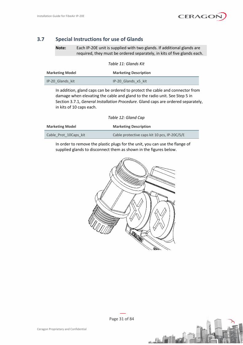
3.7 Special Instructions for use of Glands
Note: Each IP-20E unit is supplied with two glands. If additional glands are required, they must be ordered separately, in kits of five glands each.
Table 11: Glands Kit
Marketing Model Marketing Description
IP-20_Glands_kit IP-20_Glands_x5_kit
In addition, gland caps can be ordered to protect the cable and connector from damage when elevating the cable and gland to the radio unit. See Step 5 in
Section 3.7.1, General Installation Procedure. Gland caps are ordered separately, in kits of 10 caps each.
Table 12: Gland Cap
Marketing Model Marketing Description
Cable_Prot_10Caps_kit Cable protective caps kit 10 pcs, IP-20C/S/E
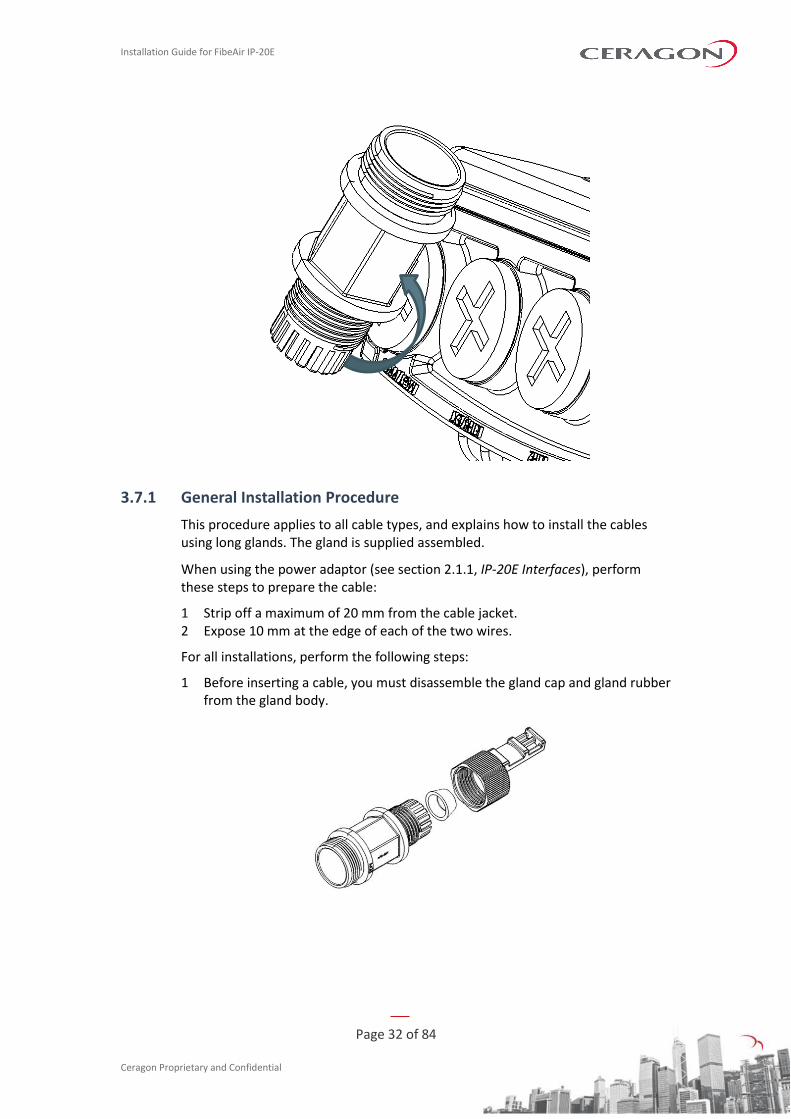
In order to remove the plastic plugs for the unit, you can use the flange of supplied glands to disconnect them as shown in the figures below.
Installation Guide for FibeAir IP-20E
Page 32 of 84
Ceragon Proprietary and Confidential
3.7.1 General Installation Procedure
This procedure applies to all cable types, and explains how to install the cables using long glands. The gland is supplied assembled.
When using the power adaptor (see section 2.1.1, IP-20E Interfaces), perform these steps to prepare the cable:
1 Strip off a maximum of 20 mm from the cable jacket. 2 Expose 10 mm at the edge of each of the two wires.
For all installations, perform the following steps:
1 Before inserting a cable, you must disassemble the gland cap and gland rubber from the gland body.
Installation Guide for FibeAir IP-20E
Page 33 of 84
Ceragon Proprietary and Confidential
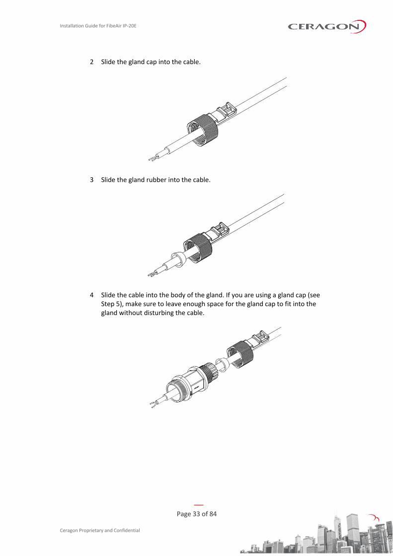
2 Slide the gland cap into the cable.
3 Slide the gland rubber into the cable.
4 Slide the cable into the body of the gland. If you are using a gland cap (see Step 5), make sure to leave enough space for the gland cap to fit into the gland without disturbing the cable.
Installation Guide for FibeAir IP-20E
Page 34 of 84
Ceragon Proprietary and Confidential
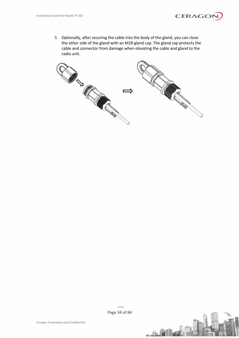
5 Optionally, after securing the cable into the body of the gland, you can close the other side of the gland with an M28 gland cap. The gland cap protects the cable and connector from damage when elevating the cable and gland to the radio unit.
Installation Guide for FibeAir IP-20E
Page 35 of 84
Ceragon Proprietary and Confidential
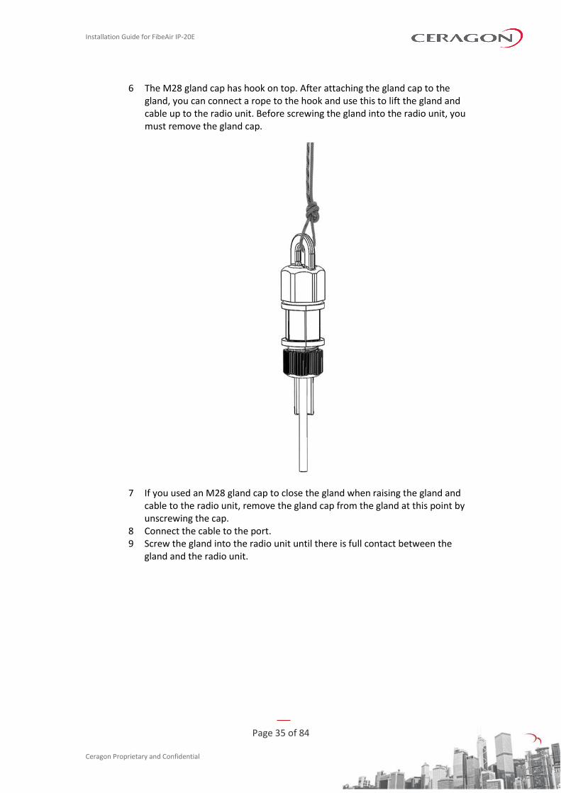
6 The M28 gland cap has hook on top. After attaching the gland cap to the gland, you can connect a rope to the hook and use this to lift the gland and cable up to the radio unit. Before screwing the gland into the radio unit, you must remove the gland cap.
7 If you used an M28 gland cap to close the gland when raising the gland and cable to the radio unit, remove the gland cap from the gland at this point by unscrewing the cap.
8 Connect the cable to the port. 9 Screw the gland into the radio unit until there is full contact between the
gland and the radio unit.
Installation Guide for FibeAir IP-20E
Page 36 of 84
Ceragon Proprietary and Confidential
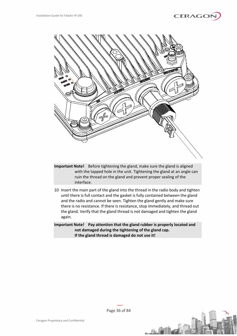
Important Note! Before tightening the gland, make sure the gland is aligned with the tapped hole in the unit. Tightening the gland at an angle can ruin the thread on the gland and prevent proper sealing of the interface.
10 Insert the main part of the gland into the thread in the radio body and tighten until there is full contact and the gasket is fully contained between the gland and the radio and cannot be seen. Tighten the gland gently and make sure there is no resistance. If there is resistance, stop immediately, and thread out the gland. Verify that the gland thread is not damaged and tighten the gland again.
Important Note! Pay attention that the gland rubber is properly located and not damaged during the tightening of the gland cap. If the gland thread is damaged do not use it!
Installation Guide for FibeAir IP-20E
Page 37 of 84
Ceragon Proprietary and Confidential
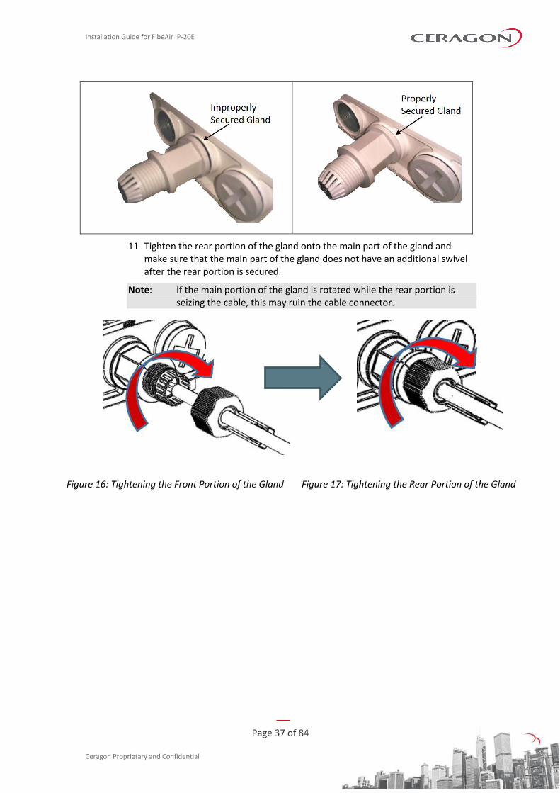
11 Tighten the rear portion of the gland onto the main part of the gland and make sure that the main part of the gland does not have an additional swivel after the rear portion is secured.
Note: If the main portion of the gland is rotated while the rear portion is seizing the cable, this may ruin the cable connector.
Figure 16: Tightening the Front Portion of the Gland Figure 17: Tightening the Rear Portion of the Gland
Installation Guide for FibeAir IP-20E
Page 38 of 84
Ceragon Proprietary and Confidential
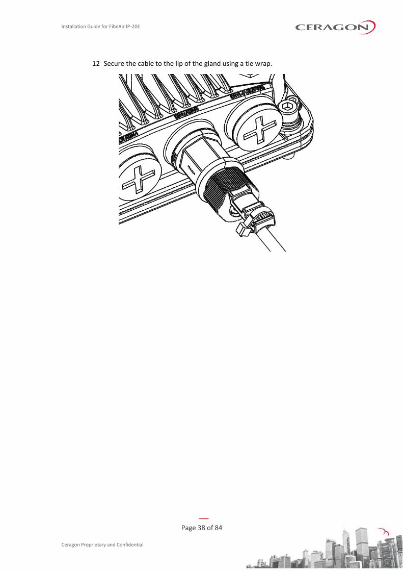
12 Secure the cable to the lip of the gland using a tie wrap.
Installation Guide for FibeAir IP-20E
Page 39 of 84
Ceragon Proprietary and Confidential
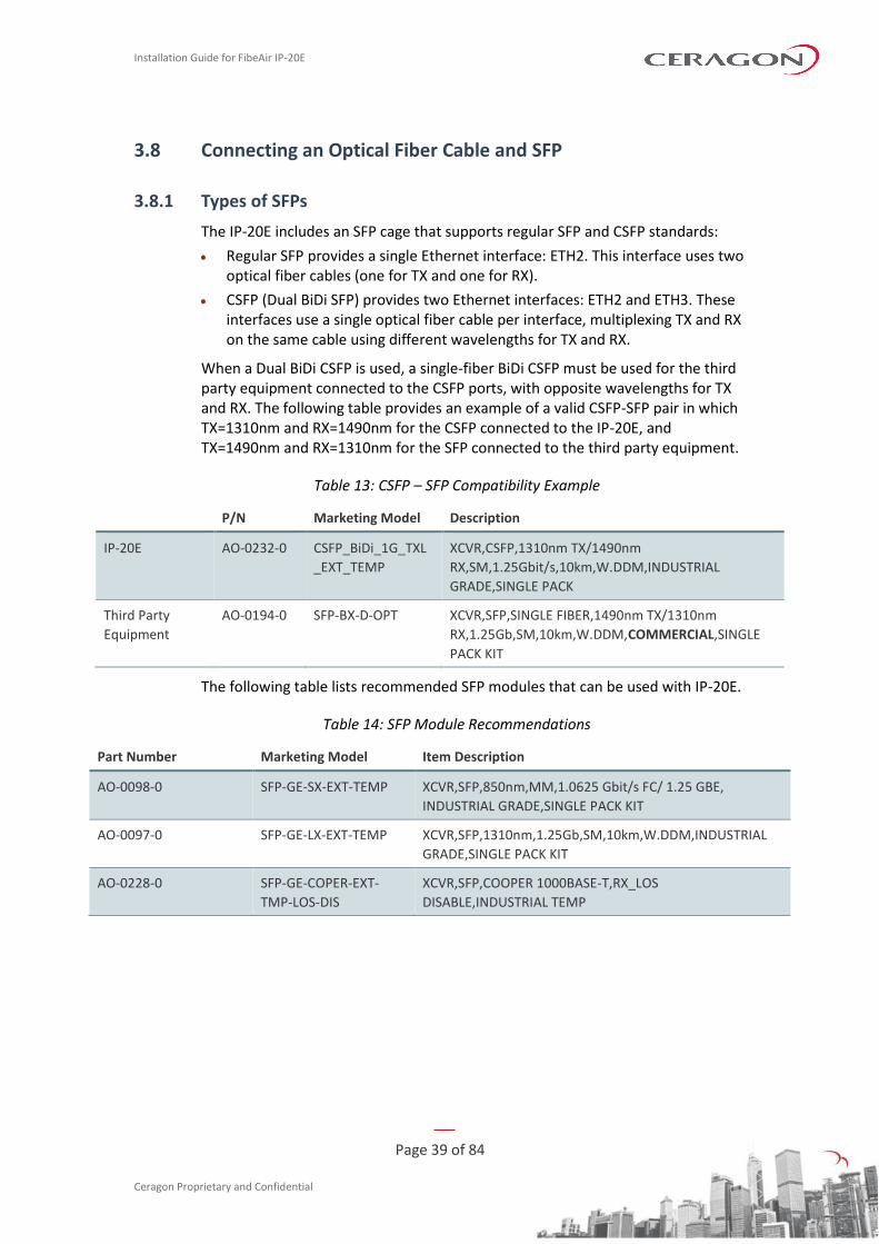
3.8 Connecting an Optical Fiber Cable and SFP
3.8.1 Types of SFPs
The IP-20E includes an SFP cage that supports regular SFP and CSFP standards:
• Regular SFP provides a single Ethernet interface: ETH2. This interface uses two optical fiber cables (one for TX and one for RX).
• CSFP (Dual BiDi SFP) provides two Ethernet interfaces: ETH2 and ETH3. These interfaces use a single optical fiber cable per interface, multiplexing TX and RX on the same cable using different wavelengths for TX and RX.
When a Dual BiDi CSFP is used, a single-fiber BiDi CSFP must be used for the third party equipment connected to the CSFP ports, with opposite wavelengths for TX and RX. The following table provides an example of a valid CSFP-SFP pair in which TX=1310nm and RX=1490nm for the CSFP connected to the IP-20E, and TX=1490nm and RX=1310nm for the SFP connected to the third party equipment.
Table 13: CSFP – SFP Compatibility Example
P/N Marketing Model Description
IP-20E AO-0232-0 CSFP_BiDi_1G_TXL
_EXT_TEMP
XCVR,CSFP,1310nm TX/1490nm
RX,SM,1.25Gbit/s,10km,W.DDM,INDUSTRIAL
GRADE,SINGLE PACK
Third Party
Equipment
AO-0194-0 SFP-BX-D-OPT XCVR,SFP,SINGLE FIBER,1490nm TX/1310nm
RX,1.25Gb,SM,10km,W.DDM,COMMERCIAL,SINGLE
PACK KIT
The following table lists recommended SFP modules that can be used with IP-20E.
Table 14: SFP Module Recommendations
Part Number Marketing Model Item Description
AO-0098-0 SFP-GE-SX-EXT-TEMP XCVR,SFP,850nm,MM,1.0625 Gbit/s FC/ 1.25 GBE,
INDUSTRIAL GRADE,SINGLE PACK KIT
AO-0097-0 SFP-GE-LX-EXT-TEMP XCVR,SFP,1310nm,1.25Gb,SM,10km,W.DDM,INDUSTRIAL
GRADE,SINGLE PACK KIT
AO-0228-0 SFP-GE-COPER-EXT-
TMP-LOS-DIS
XCVR,SFP,COOPER 1000BASE-T,RX_LOS
DISABLE,INDUSTRIAL TEMP
Installation Guide for FibeAir IP-20E
Page 40 of 84
Ceragon Proprietary and Confidential
The following table lists recommended CSFP modules that can be used with IP-20E.
Table 15: CSFP Module Recommendations
Part Number Marketing Model Item Description
AO-0232-0 CSFP_BiDi_1G_TXL_EXT_TEMP XCVR,CSFP,1310nm TX/1490nm
RX,SM,1.25Gbit/s,10km,W.DDM,INDUSTRIAL
GRADE,SINGLE PACK
AO-0231-0 CSFP_BiDi_1G_TXH_EXT_TEMP XCVR,CSFP,1490nm TX/1310nm
RX,SM,1.25Gbit/s,10km,W.DDM,INDUSTRIAL
GRADE,SINGLE PACK
The following table lists recommended SFP modules that can be used with third party equipment connected to a CSFP module on the IP-20E.
Table 16: SFP Module Recommendations for Third Party Equipment
Part Number Marketing Model Item Description
AO-0194-0 SFP-BX-D-OPT XCVR,SFP,SINGLE FIBER,1490nm TX/1310nm
RX,1.25Gb,SM,10km,W.DDM,COMMERCIAL,SINGLE
PACK KIT
AO-0193-0 SFP-BX-U-OPT XCVR,SFP,SINGLE FIBER,1310nm TX/1490nm
RX,1.25Gb,SM,10km,W.DDM,COMMERCIAL,SINGLE
PACK KIT
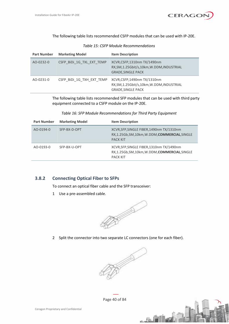
3.8.2 Connecting Optical Fiber to SFPs
To connect an optical fiber cable and the SFP transceiver:
1 Use a pre-assembled cable.
2 Split the connector into two separate LC connectors (one for each fiber).
Installation Guide for FibeAir IP-20E
Page 41 of 84
Ceragon Proprietary and Confidential
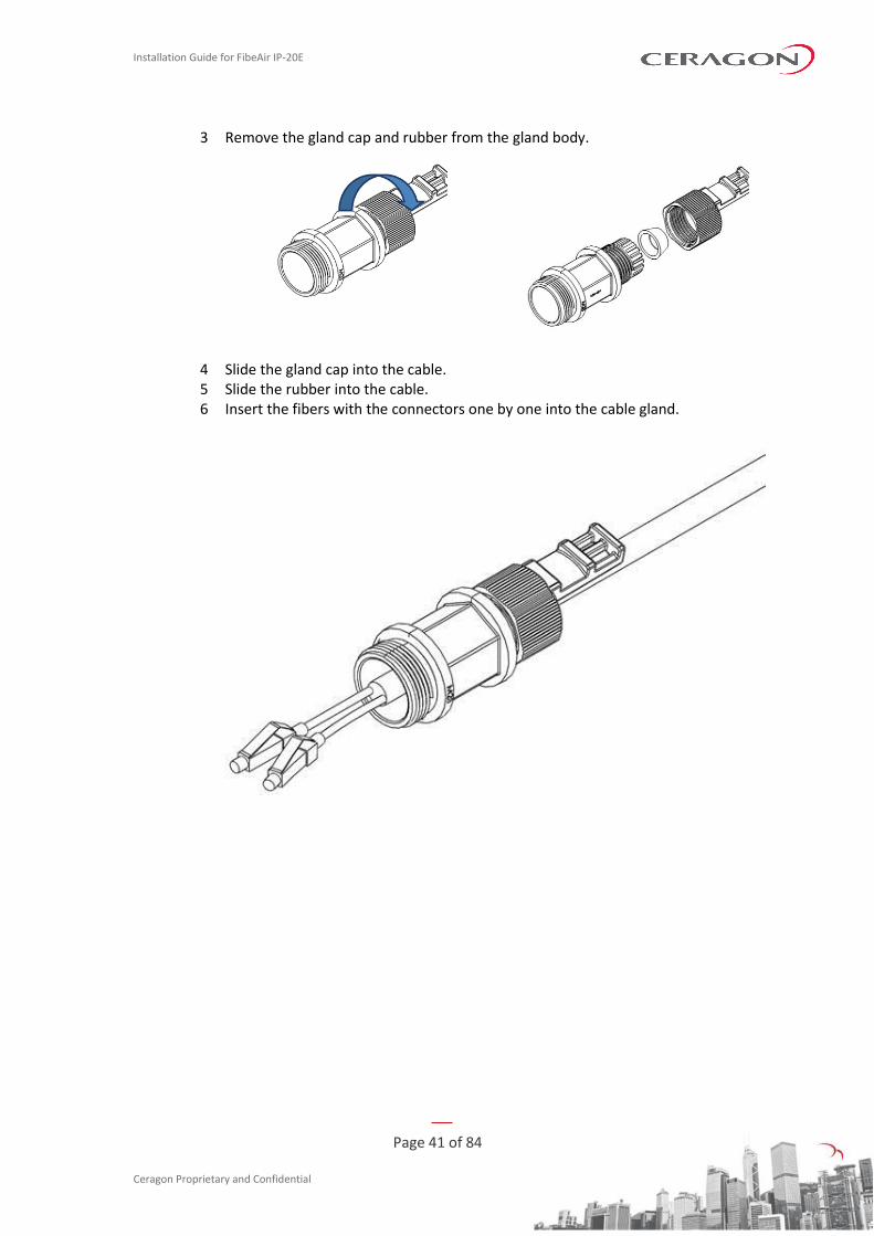
3 Remove the gland cap and rubber from the gland body.
4 Slide the gland cap into the cable. 5 Slide the rubber into the cable. 6 Insert the fibers with the connectors one by one into the cable gland.
Installation Guide for FibeAir IP-20E
Page 42 of 84
Ceragon Proprietary and Confidential
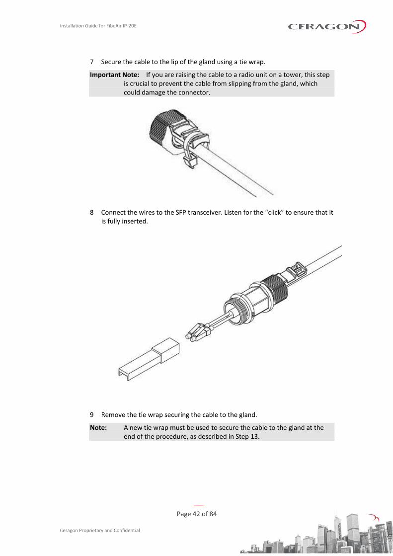
7 Secure the cable to the lip of the gland using a tie wrap.
Important Note: If you are raising the cable to a radio unit on a tower, this step is crucial to prevent the cable from slipping from the gland, which could damage the connector.
8 Connect the wires to the SFP transceiver. Listen for the “click” to ensure that it is fully inserted.
9 Remove the tie wrap securing the cable to the gland.
Note: A new tie wrap must be used to secure the cable to the gland at the end of the procedure, as described in Step 13.
Installation Guide for FibeAir IP-20E
Page 43 of 84
Ceragon Proprietary and Confidential
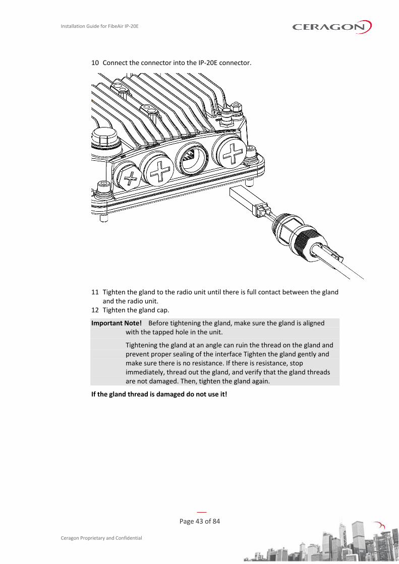
10 Connect the connector into the IP-20E connector.
11 Tighten the gland to the radio unit until there is full contact between the gland and the radio unit.
12 Tighten the gland cap.
Important Note! Before tightening the gland, make sure the gland is aligned with the tapped hole in the unit.
Tightening the gland at an angle can ruin the thread on the gland and prevent proper sealing of the interface Tighten the gland gently and make sure there is no resistance. If there is resistance, stop immediately, thread out the gland, and verify that the gland threads are not damaged. Then, tighten the gland again.
If the gland thread is damaged do not use it!
Installation Guide for FibeAir IP-20E
Page 44 of 84
Ceragon Proprietary and Confidential
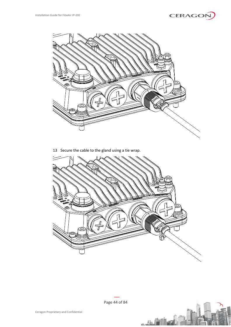
13 Secure the cable to the gland using a tie wrap.
Installation Guide for FibeAir IP-20E
Page 45 of 84
Ceragon Proprietary and Confidential
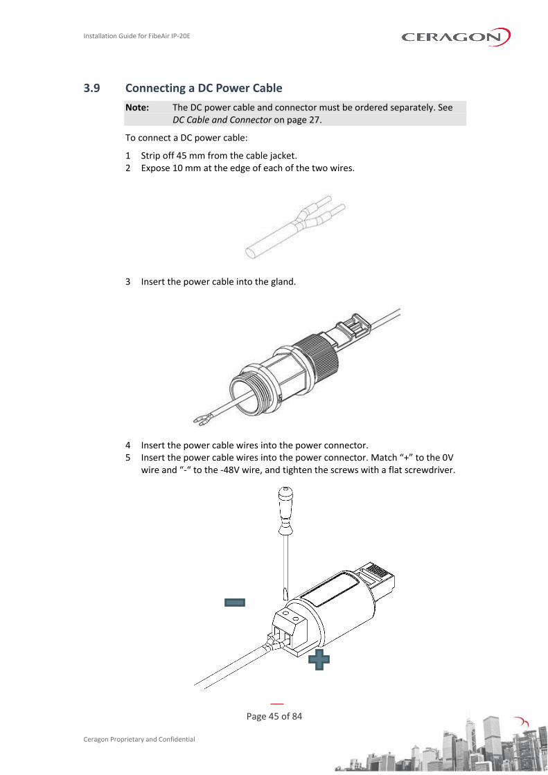
3.9 Connecting a DC Power Cable
Note: The DC power cable and connector must be ordered separately. See DC Cable and Connector on page 27.
To connect a DC power cable:
1 Strip off 45 mm from the cable jacket. 2 Expose 10 mm at the edge of each of the two wires.
3 Insert the power cable into the gland.
4 Insert the power cable wires into the power connector. 5 Insert the power cable wires into the power connector. Match “+” to the 0V
wire and “-“ to the -48V wire, and tighten the screws with a flat screwdriver.
Installation Guide for FibeAir IP-20E
Page 46 of 84
Ceragon Proprietary and Confidential
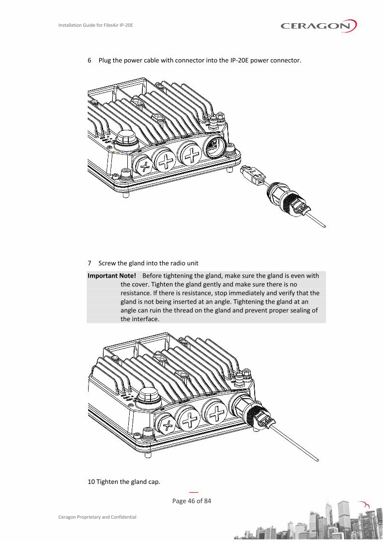
6 Plug the power cable with connector into the IP-20E power connector.
7 Screw the gland into the radio unit
Important Note! Before tightening the gland, make sure the gland is even with the cover. Tighten the gland gently and make sure there is no resistance. If there is resistance, stop immediately and verify that the gland is not being inserted at an angle. Tightening the gland at an angle can ruin the thread on the gland and prevent proper sealing of the interface.
10 Tighten the gland cap.
Installation Guide for FibeAir IP-20E
Page 47 of 84
Ceragon Proprietary and Confidential
11 Secure the cable to the gland with a tie wrap.
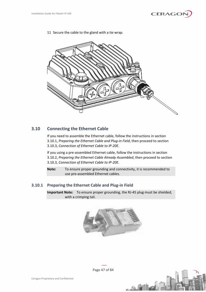
3.10 Connecting the Ethernet Cable
If you need to assemble the Ethernet cable, follow the instructions in section
3.10.1, Preparing the Ethernet Cable and Plug-in Field, then proceed to section
3.10.3, Connection of Ethernet Cable to IP-20E.
If you using a pre-assembled Ethernet cable, follow the instructions in section
3.10.2, Preparing the Ethernet Cable Already Assembled, then proceed to section
3.10.3, Connection of Ethernet Cable to IP-20E.
Note: To ensure proper grounding and connectivity, it is recommended to use pre-assembled Ethernet cables.
3.10.1 Preparing the Ethernet Cable and Plug-in Field
Important Note: To ensure proper grounding, the RJ-45 plug must be shielded, with a crimping tail.
Installation Guide for FibeAir IP-20E
Page 48 of 84
Ceragon Proprietary and Confidential
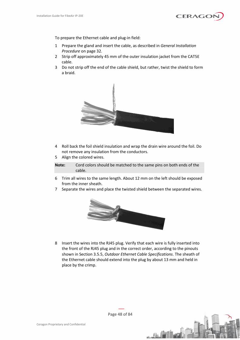
To prepare the Ethernet cable and plug-in field:
1 Prepare the gland and insert the cable, as described in General Installation Procedure on page 32.
2 Strip off approximately 45 mm of the outer insulation jacket from the CAT5E cable.
3 Do not strip off the end of the cable shield, but rather, twist the shield to form a braid.
4 Roll back the foil shield insulation and wrap the drain wire around the foil. Do not remove any insulation from the conductors.
5 Align the colored wires.
Note: Cord colors should be matched to the same pins on both ends of the cable.
6 Trim all wires to the same length. About 12 mm on the left should be exposed from the inner sheath.
7 Separate the wires and place the twisted shield between the separated wires.
8 Insert the wires into the RJ45 plug. Verify that each wire is fully inserted into the front of the RJ45 plug and in the correct order, according to the pinouts
shown in Section 3.5.5, Outdoor Ethernet Cable Specifications. The sheath of the Ethernet cable should extend into the plug by about 13 mm and held in place by the crimp.
Installation Guide for FibeAir IP-20E
Page 49 of 84
Ceragon Proprietary and Confidential
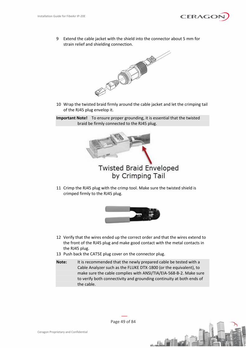
9 Extend the cable jacket with the shield into the connector about 5 mm for strain relief and shielding connection.
10 Wrap the twisted braid firmly around the cable jacket and let the crimping tail of the RJ45 plug envelop it.
Important Note! To ensure proper grounding, it is essential that the twisted braid be firmly connected to the RJ45 plug.
11 Crimp the RJ45 plug with the crimp tool. Make sure the twisted shield is crimped firmly to the RJ45 plug.
12 Verify that the wires ended up the correct order and that the wires extend to the front of the RJ45 plug and make good contact with the metal contacts in the RJ45 plug.
13 Push back the CAT5E plug cover on the connector plug.
Note: It is recommended that the newly prepared cable be tested with a Cable Analyzer such as the FLUKE DTX-1800 (or the equivalent), to make sure the cable complies with ANSI/TIA/EIA-568-B-2. Make sure to verify both connectivity and grounding continuity at both ends of the cable.
Installation Guide for FibeAir IP-20E
Page 50 of 84
Ceragon Proprietary and Confidential
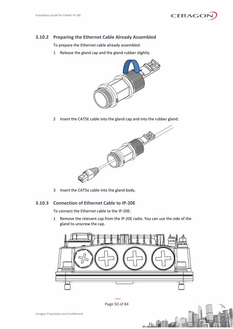
3.10.2 Preparing the Ethernet Cable Already Assembled
To prepare the Ethernet cable already assembled:
1 Release the gland cap and the gland rubber slightly.
2 Insert the CAT5E cable into the gland cap and into the rubber gland.
3 Insert the CAT5e cable into the gland body.
3.10.3 Connection of Ethernet Cable to IP-20E
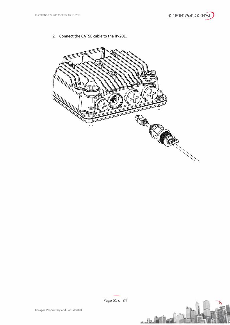
To connect the Ethernet cable to the IP-20E:
1 Remove the relevant cap from the IP-20E radio. You can use the side of the gland to unscrew the cap.
Installation Guide for FibeAir IP-20E
Page 51 of 84
Ceragon Proprietary and Confidential
2 Connect the CAT5E cable to the IP-20E.
Installation Guide for FibeAir IP-20E
Page 52 of 84
Ceragon Proprietary and Confidential
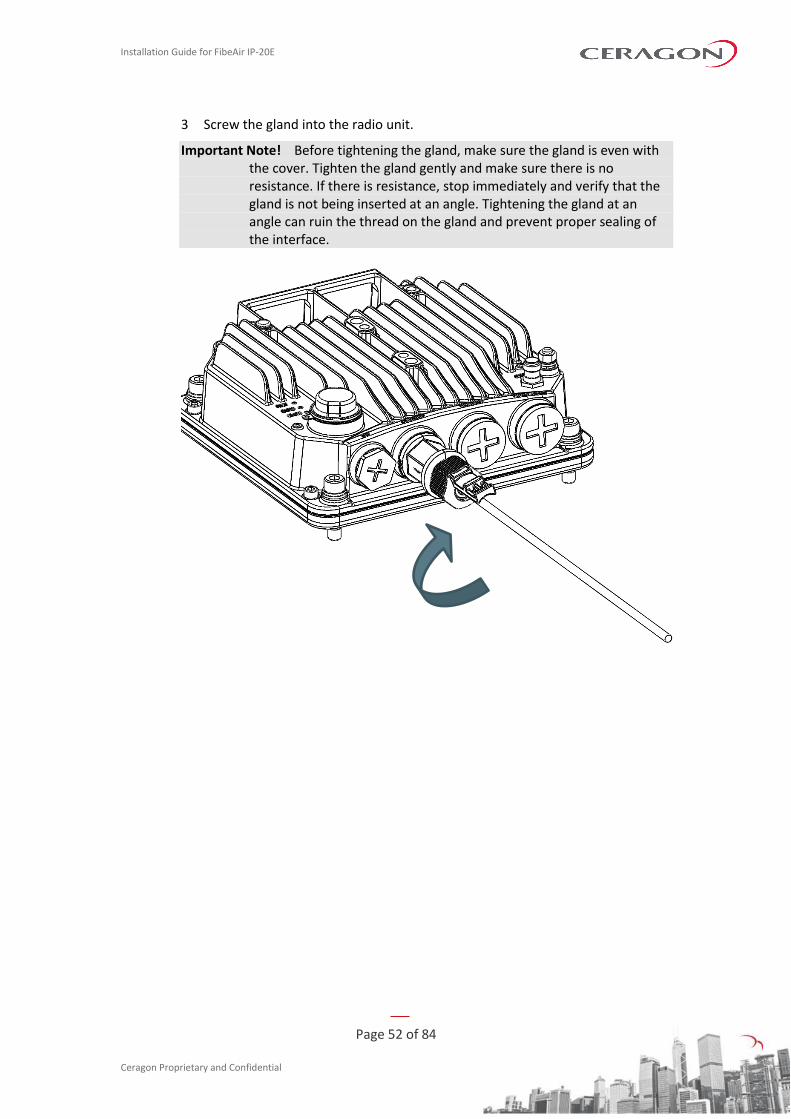
3 Screw the gland into the radio unit.
Important Note! Before tightening the gland, make sure the gland is even with the cover. Tighten the gland gently and make sure there is no resistance. If there is resistance, stop immediately and verify that the gland is not being inserted at an angle. Tightening the gland at an angle can ruin the thread on the gland and prevent proper sealing of the interface.
Installation Guide for FibeAir IP-20E
Page 53 of 84
Ceragon Proprietary and Confidential
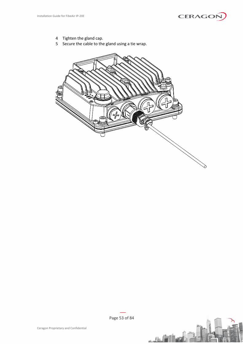
4 Tighten the gland cap. 5 Secure the cable to the gland using a tie wrap.
Installation Guide for FibeAir IP-20E
Page 54 of 84
Ceragon Proprietary and Confidential
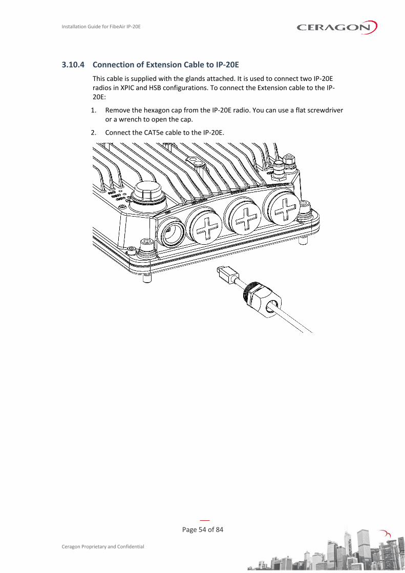
3.10.4 Connection of Extension Cable to IP-20E
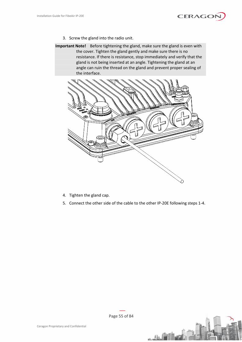
This cable is supplied with the glands attached. It is used to connect two IP-20E radios in XPIC and HSB configurations. To connect the Extension cable to the IP-20E:
1. Remove the hexagon cap from the IP-20E radio. You can use a flat screwdriver or a wrench to open the cap.
2. Connect the CAT5e cable to the IP-20E.
Installation Guide for FibeAir IP-20E
Page 55 of 84
Ceragon Proprietary and Confidential
3. Screw the gland into the radio unit.
Important Note! Before tightening the gland, make sure the gland is even with the cover. Tighten the gland gently and make sure there is no resistance. If there is resistance, stop immediately and verify that the gland is not being inserted at an angle. Tightening the gland at an angle can ruin the thread on the gland and prevent proper sealing of the interface.
4. Tighten the gland cap.
5. Connect the other side of the cable to the other IP-20E following steps 1-4.
Installation Guide for FibeAir IP-20E
Page 56 of 84
Ceragon Proprietary and Confidential
4. PoE Injector Installation and Connection
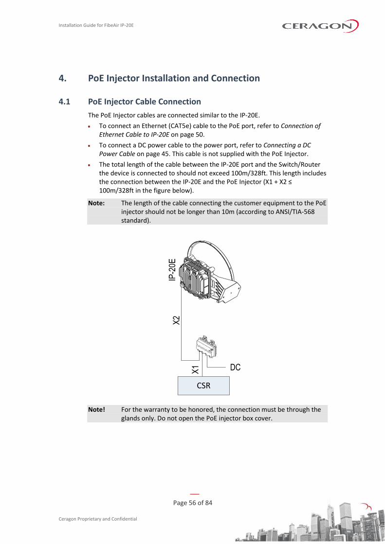
4.1 PoE Injector Cable Connection
The PoE Injector cables are connected similar to the IP-20E.
• To connect an Ethernet (CAT5e) cable to the PoE port, refer to Connection of Ethernet Cable to IP-20E on page 50.
• To connect a DC power cable to the power port, refer to Connecting a DC Power Cable on page 45. This cable is not supplied with the PoE Injector.
• The total length of the cable between the IP-20E port and the Switch/Router the device is connected to should not exceed 100m/328ft. This length includes the connection between the IP-20E and the PoE Injector (X1 + X2 ≤ 100m/328ft in the figure below).
Note: The length of the cable connecting the customer equipment to the PoE injector should not be longer than 10m (according to ANSI/TIA-568 standard).
IP-2
0EX
2
DCX1
CSR
Note! For the warranty to be honored, the connection must be through the glands only. Do not open the PoE injector box cover.
Installation Guide for FibeAir IP-20E
Page 57 of 84
Ceragon Proprietary and Confidential
4.2 PoE Injector Grounding
To ground the PoE Injector:
1 On the right side of each PoE Injector, loosen the screw, plain washer, and serrated washer.
2 Place the cable lug (supplied with the PoE injector kit) between the plain and serrated washer.
3 Tighten the screw. 4 Perform a resistance test between the 2 lugs of the GND cable. Verify that the
result is 0-2 ohms.
4.3 PoE Injector Wall Mount Installation
List of Items
Item Description Quantity Remarks
1 PoE Injector 1
1 Glands Kit 1 For outdoor installations.
Note: Glands are required for outdoor installations. The glands kit (three or five glands) is not supplied with the PoE Injector, and must be ordered separately.
Glands Kit
Marketing Model Marketing Description
IP-20_3xGlands_kit IP-20_3xGlands_kit
IP-20_Glands_kit IP-20_Glands_x5_kit
Required Tools
• Metric offset wrench key wrench set
• Hammer
• Drilling Machine
Procedure
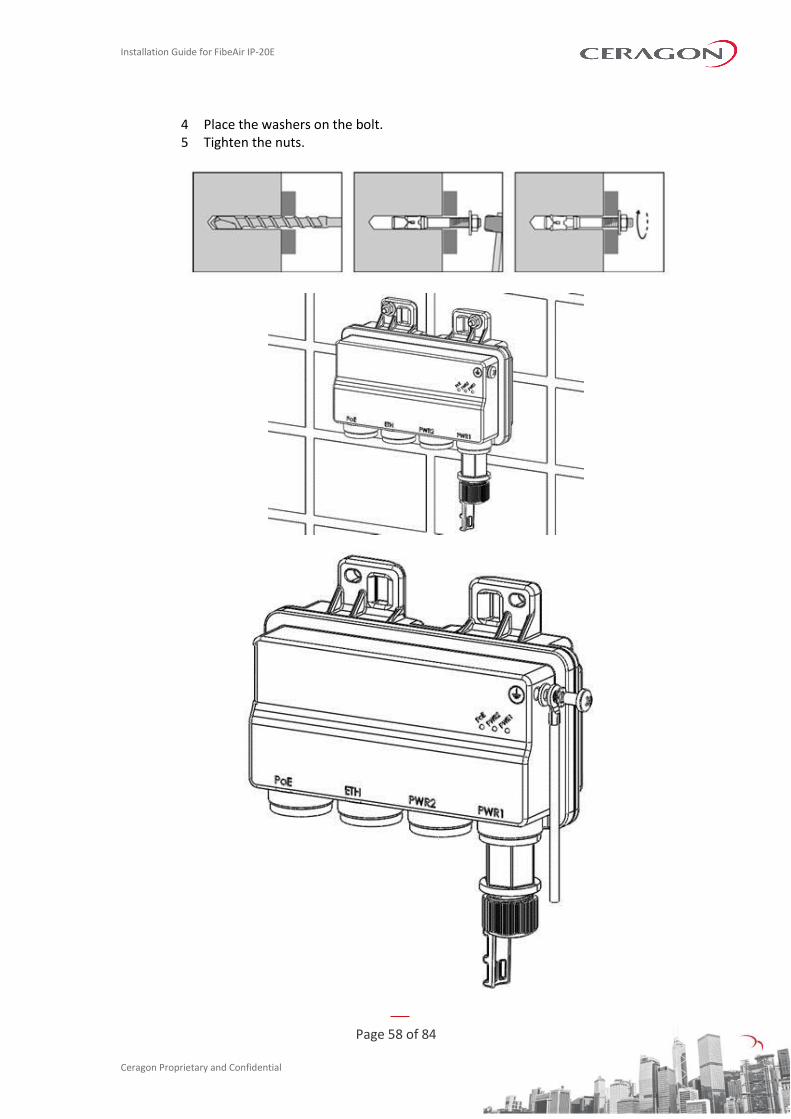
1 Mount and tighten the PoE Injector to a wall using two M6 bolts and anchors. The M6 bolts and anchors must be purchased separately.
Note: Use Anchor Stainless Steel with flanged Hexagonal nut M6X70.
2 Drill two 6mm diameter holes with 100mm distance between the center of the holes.
3 Insert the anchors with the bolts.
Installation Guide for FibeAir IP-20E
Page 58 of 84
Ceragon Proprietary and Confidential
4 Place the washers on the bolt. 5 Tighten the nuts.
Installation Guide for FibeAir IP-20E
Page 59 of 84
Ceragon Proprietary and Confidential
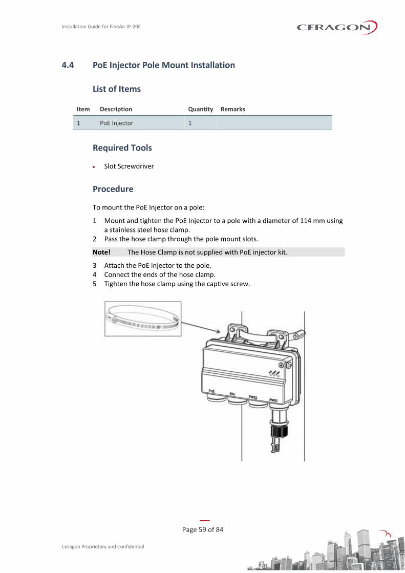
4.4 PoE Injector Pole Mount Installation
List of Items
Item Description Quantity Remarks
1 PoE Injector 1
Required Tools
• Slot Screwdriver
Procedure
To mount the PoE Injector on a pole:
1 Mount and tighten the PoE Injector to a pole with a diameter of 114 mm using a stainless steel hose clamp.
2 Pass the hose clamp through the pole mount slots.
Note! The Hose Clamp is not supplied with PoE injector kit.
3 Attach the PoE injector to the pole. 4 Connect the ends of the hose clamp. 5 Tighten the hose clamp using the captive screw.
Installation Guide for FibeAir IP-20E
Page 60 of 84
Ceragon Proprietary and Confidential
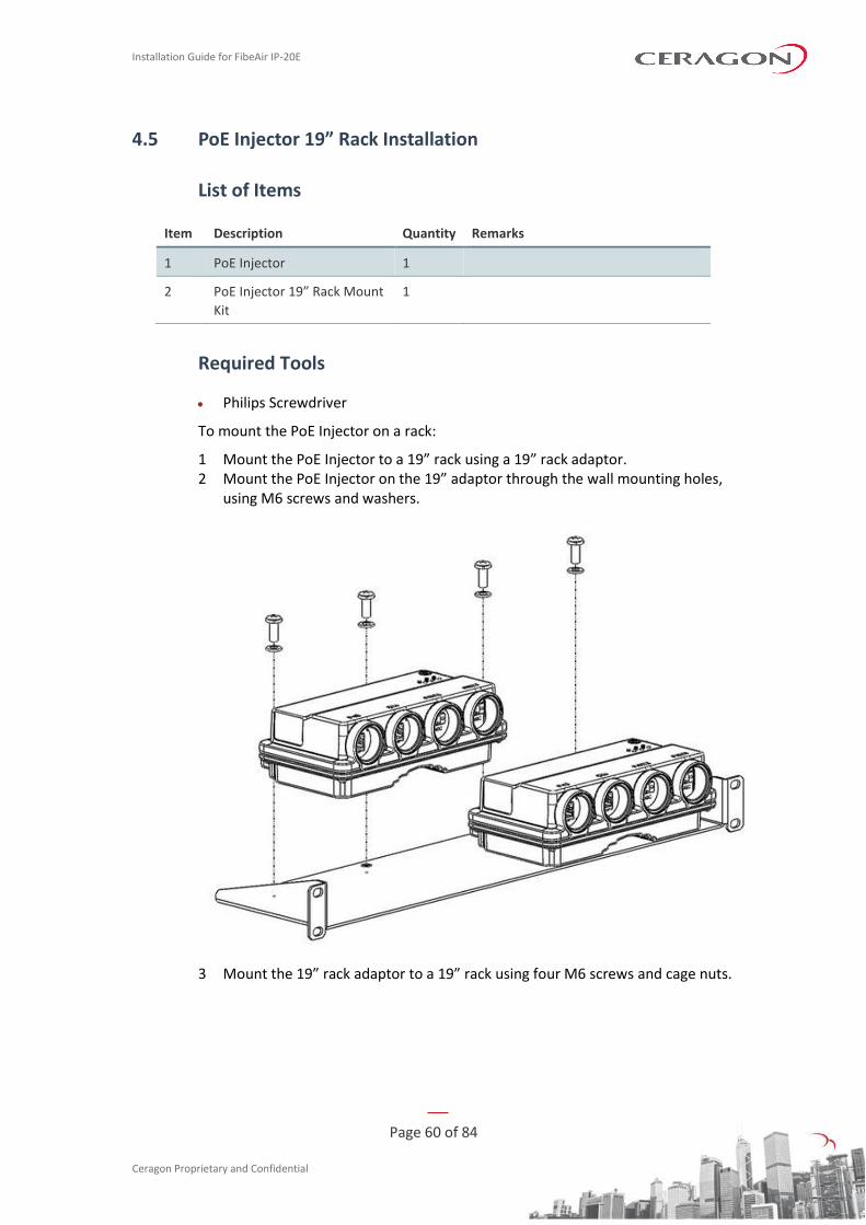
4.5 PoE Injector 19” Rack Installation
List of Items
Item Description Quantity Remarks
1 PoE Injector 1
2 PoE Injector 19” Rack Mount
Kit
1
Required Tools
• Philips Screwdriver
To mount the PoE Injector on a rack:
1 Mount the PoE Injector to a 19” rack using a 19” rack adaptor. 2 Mount the PoE Injector on the 19” adaptor through the wall mounting holes,
using M6 screws and washers.
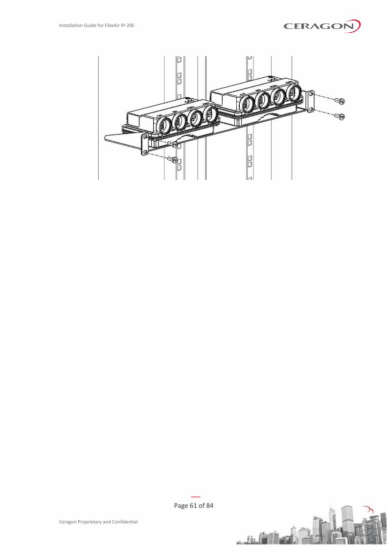
3 Mount the 19” rack adaptor to a 19” rack using four M6 screws and cage nuts.
Installation Guide for FibeAir IP-20E
Page 61 of 84
Ceragon Proprietary and Confidential
Installation Guide for FibeAir IP-20E
Page 62 of 84
Ceragon Proprietary and Confidential
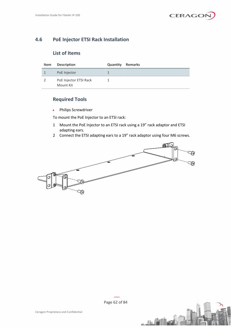
4.6 PoE Injector ETSI Rack Installation
List of Items
Item Description Quantity Remarks
1 PoE Injector 1
2 PoE Injector ETSI Rack
Mount Kit
1
Required Tools
• Philips Screwdriver
To mount the PoE Injector to an ETSI rack:
1 Mount the PoE Injector to an ETSI rack using a 19” rack adaptor and ETSI adapting ears.
2 Connect the ETSI adapting ears to a 19” rack adaptor using four M6 screws.
Installation Guide for FibeAir IP-20E
Page 63 of 84
Ceragon Proprietary and Confidential
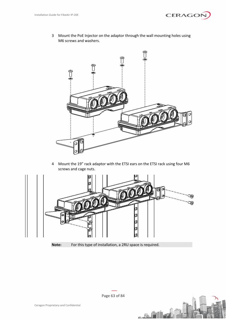
3 Mount the PoE Injector on the adaptor through the wall mounting holes using M6 screws and washers.
4 Mount the 19” rack adaptor with the ETSI ears on the ETSI rack using four M6 screws and cage nuts.
Note: For this type of installation, a 2RU space is required.
Installation Guide for FibeAir IP-20E
Page 64 of 84
Ceragon Proprietary and Confidential
5. Generic Installation Procedures and Notes
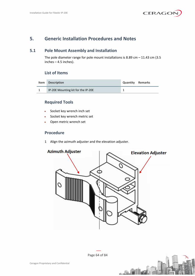
5.1 Pole Mount Assembly and Installation
The pole diameter range for pole mount installations is 8.89 cm – 11.43 cm (3.5 inches – 4.5 inches).
List of Items
Item Description Quantity Remarks
1 IP-20E Mounting kit for the IP-20E 1
Required Tools
• Socket key wrench inch set
• Socket key wrench metric set
• Open metric wrench set
Procedure
1 Align the azimuth adjuster and the elevation adjuster.
Installation Guide for FibeAir IP-20E
Page 65 of 84
Ceragon Proprietary and Confidential
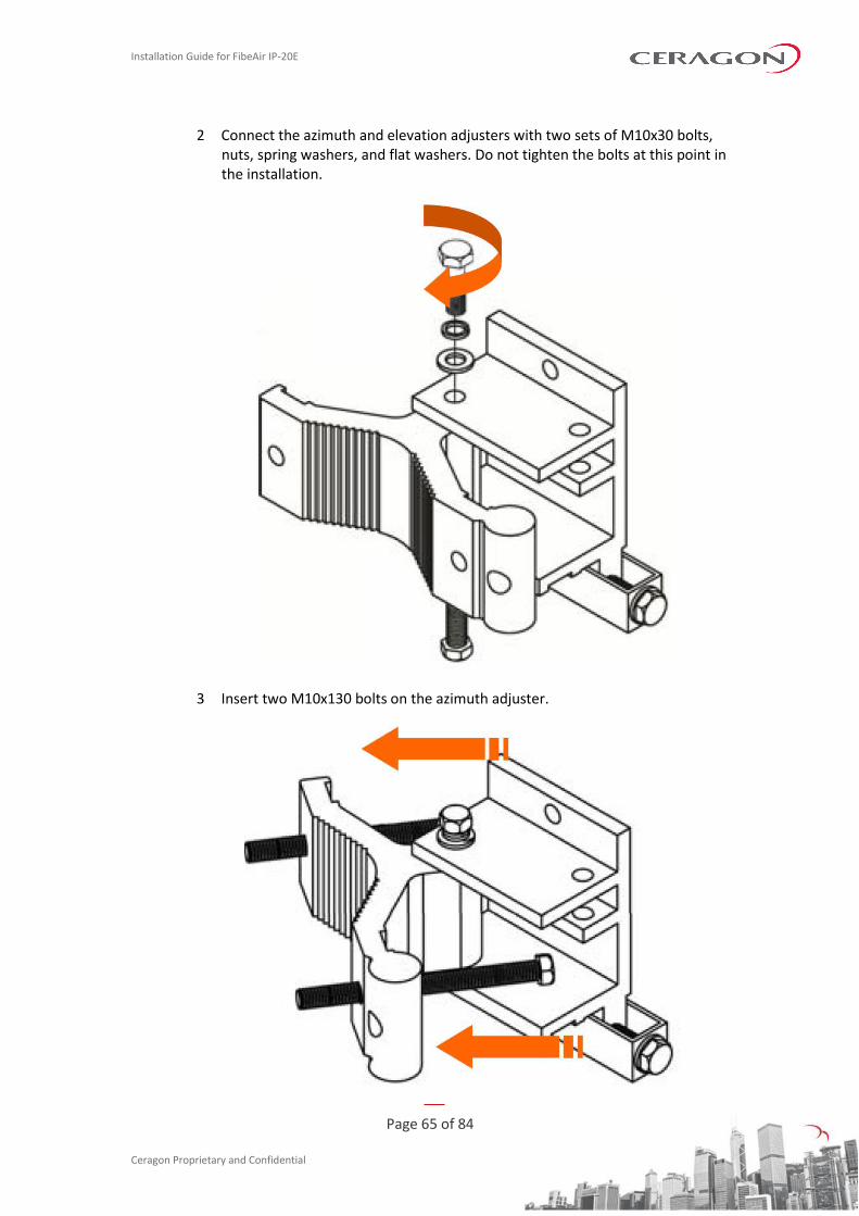
2 Connect the azimuth and elevation adjusters with two sets of M10x30 bolts, nuts, spring washers, and flat washers. Do not tighten the bolts at this point in the installation.
3 Insert two M10x130 bolts on the azimuth adjuster.
Installation Guide for FibeAir IP-20E
Page 66 of 84
Ceragon Proprietary and Confidential
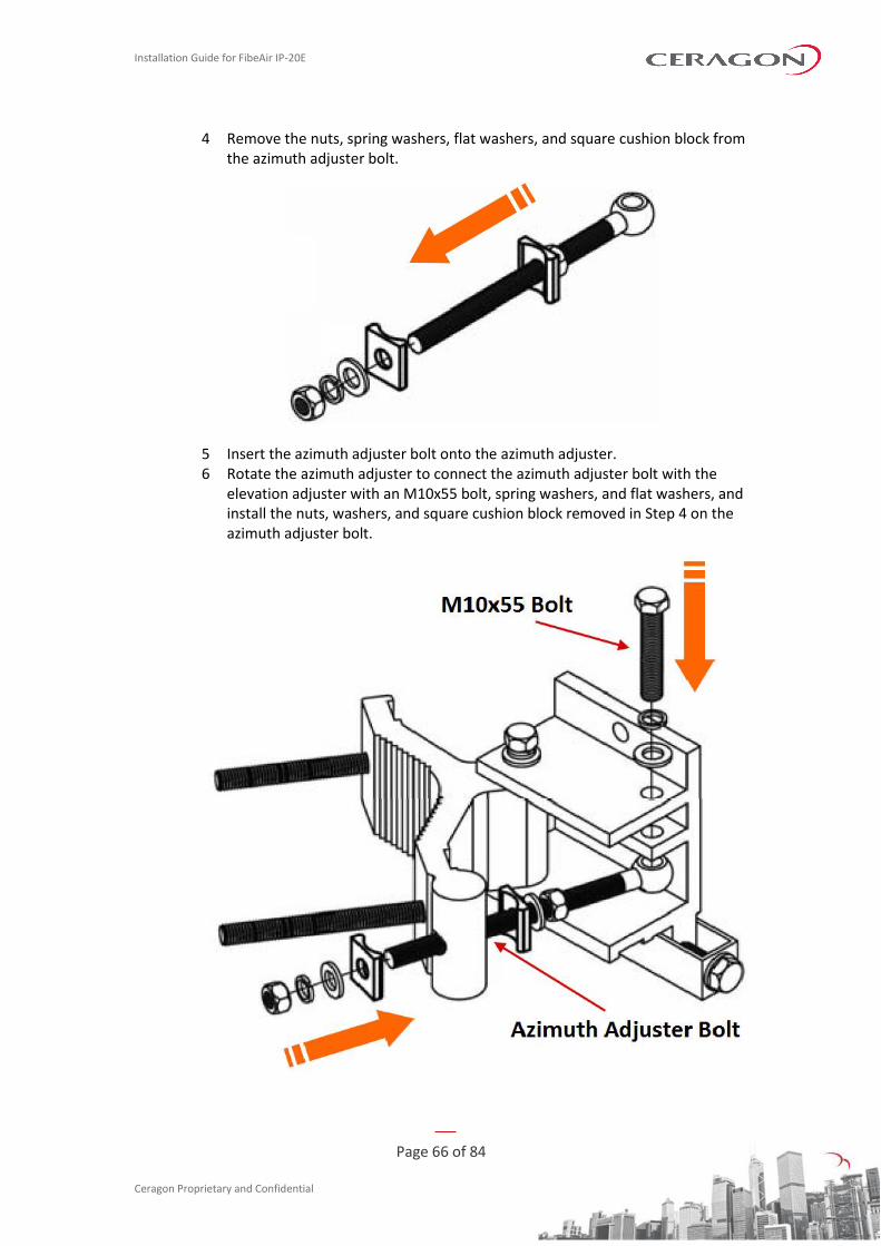
4 Remove the nuts, spring washers, flat washers, and square cushion block from the azimuth adjuster bolt.
5 Insert the azimuth adjuster bolt onto the azimuth adjuster. 6 Rotate the azimuth adjuster to connect the azimuth adjuster bolt with the
elevation adjuster with an M10x55 bolt, spring washers, and flat washers, and install the nuts, washers, and square cushion block removed in Step 4 on the azimuth adjuster bolt.
Installation Guide for FibeAir IP-20E
Page 67 of 84
Ceragon Proprietary and Confidential
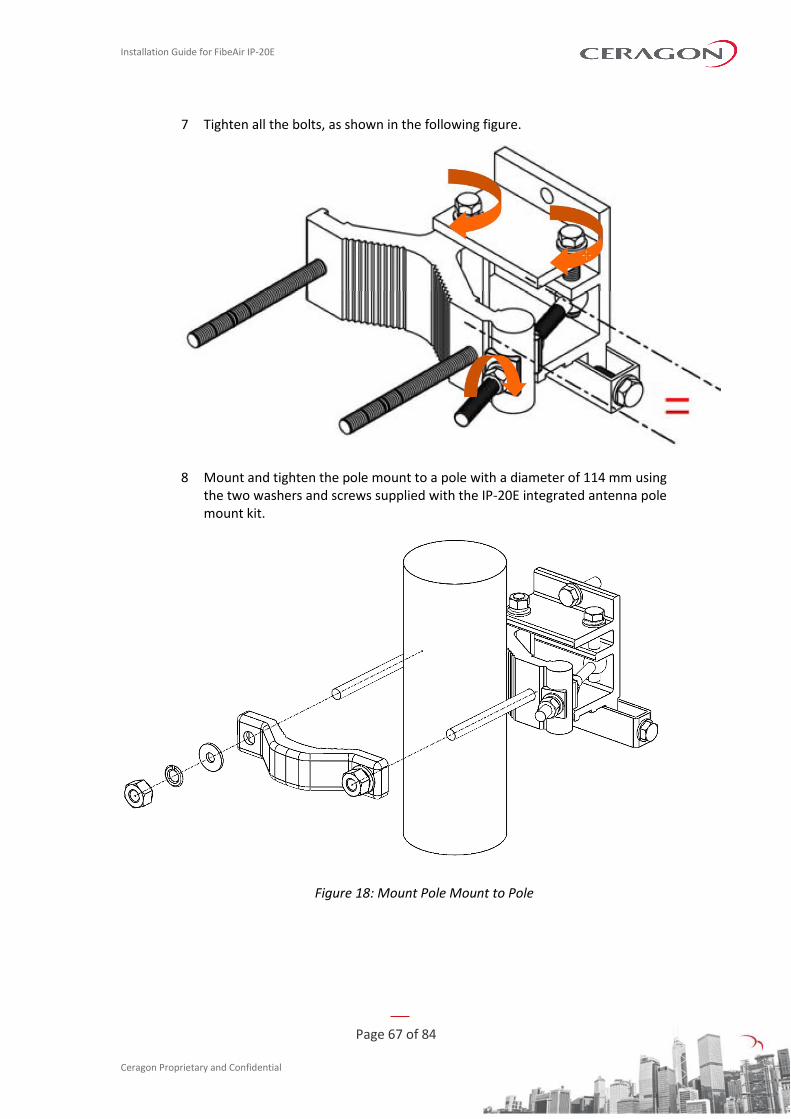
7 Tighten all the bolts, as shown in the following figure.
8 Mount and tighten the pole mount to a pole with a diameter of 114 mm using the two washers and screws supplied with the IP-20E integrated antenna pole mount kit.
Figure 18: Mount Pole Mount to Pole

Installation Guide for FibeAir IP-20E
Page 68 of 84
Ceragon Proprietary and Confidential
5.2 Performing Antenna Alignment Using the Integrated Antenna Pole Mount
You can perform adjustments to the azimuth and elevation of the antenna by turning bolts on the pole mount.
5.2.1 Adjusting the Antenna’s Azimuth
5.2.1.1 Large-Scale Azimuth Adjustment
To perform large-scale azimuth adjustment:
1 Loosen the two nuts ( in the figure above) on the clamp ( in the figure above) on the pole mount.
2 Push the pole mount softly, by hand. The pole mount is adjustable 360° around the pole.
5.2.1.2 Fine Azimuth Adjustment
To perform fine azimuth adjustment:
1 Loosen the top and bottom fixed bolts on the azimuth axis ( in the figure above).
Installation Guide for FibeAir IP-20E
Page 69 of 84
Ceragon Proprietary and Confidential
2 Loosen the two nuts and bolts ( and in the figure above) on the fine adjusting bolt ( in the figure above).
3 Move the adjusting nut ( in the figure above) slowly backwards and forwards to adjust the antenna azimuth within ±15°.
4 Tighten the top and bottom fixed bolts and the nuts and bolts on the fine adjusting bolt.
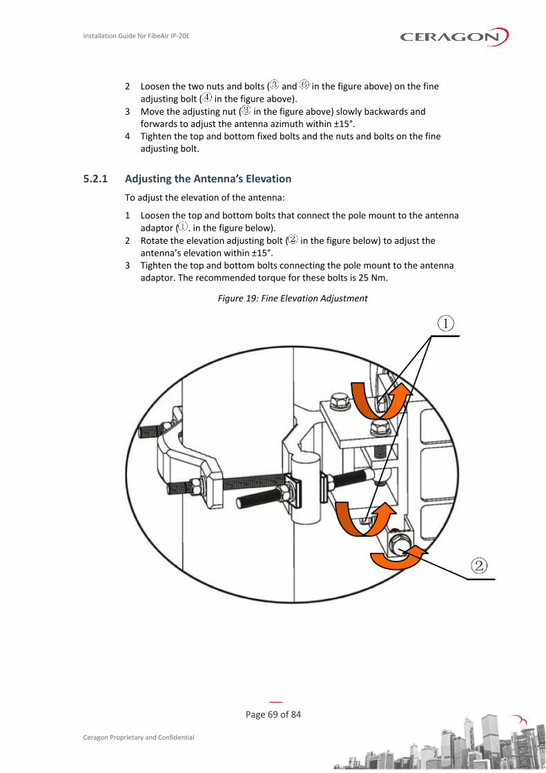
5.2.1 Adjusting the Antenna’s Elevation
To adjust the elevation of the antenna:
1 Loosen the top and bottom bolts that connect the pole mount to the antenna adaptor ( . in the figure below).
2 Rotate the elevation adjusting bolt ( in the figure below) to adjust the antenna’s elevation within ±15°.
3 Tighten the top and bottom bolts connecting the pole mount to the antenna adaptor. The recommended torque for these bolts is 25 Nm.
Figure 19: Fine Elevation Adjustment
Installation Guide for FibeAir IP-20E
Page 70 of 84
Ceragon Proprietary and Confidential
6. IP-20E Detailed Configurations Description
6.1 1+0 Direct Mount Installation
List of Items
Item Description Quantity Remarks
1 IP-20E RADIO 1
Required Tools
The following tools are required for the IP-20E installation:
• Metric offset hexagon key wrench #6
• Phillips #2 screwdriver
Procedure
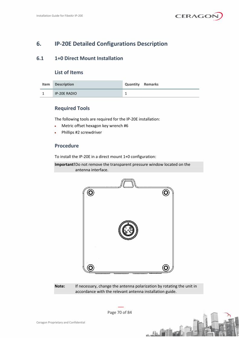
To install the IP-20E in a direct mount 1+0 configuration:
Important! Do not remove the transparent pressure window located on the antenna interface.
Note: If necessary, change the antenna polarization by rotating the unit in accordance with the relevant antenna installation guide.
Installation Guide for FibeAir IP-20E
Page 71 of 84
Ceragon Proprietary and Confidential
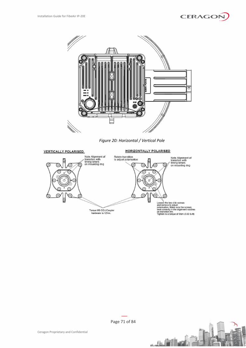
Figure 20: Horizontal / Vertical Pole
Installation Guide for FibeAir IP-20E
Page 72 of 84
Ceragon Proprietary and Confidential
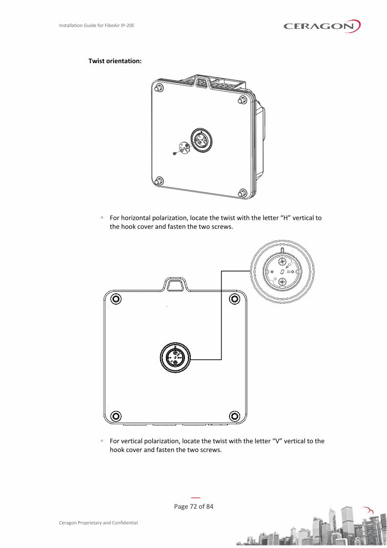
Twist orientation:
◦ For horizontal polarization, locate the twist with the letter “H” vertical to the hook cover and fasten the two screws.
◦ For vertical polarization, locate the twist with the letter “V” vertical to the hook cover and fasten the two screws.

Installation Guide for FibeAir IP-20E
Page 73 of 84
Ceragon Proprietary and Confidential
1 Mount the IP-20E on the antenna using the four M8 captive screws and washers that are supplied, assembled, in the IP-20E, and tighten the screws.
Note: Make sure the polarization mounting direction of the IP-20E is correct.
Installation Guide for FibeAir IP-20E
Page 74 of 84
Ceragon Proprietary and Confidential
6.2 1+0 with 43 dBi Flat Antenna
List of Items
Item Description Quantity Remarks
1 IP-20E RADIO with 43 dBi FLAT
ANTENNA
1
2 IP-20E Mounting kit for the IP-20E 1
Required Tools
The following tools are required for the IP-20E installation:
• Metric wrench #13 and #16
Procedure
When you order an IP-20E with a 43 dBi flat antenna, the radio and antenna are delivered together as a single unit. The polarization is determined by the placement of the radio-antenna unit. To comply with Class 2 RPE pattern, the unit must be installed in a diamond-shaped position, so that the vertical polarization is either 45° to the right (V+45) or 45° to the left (V-45). The letters “A” and “B” are placed on the upper corners of the radio to help the installer to position the unit with the correct polarization.
Installation Guide for FibeAir IP-20E
Page 75 of 84
Ceragon Proprietary and Confidential
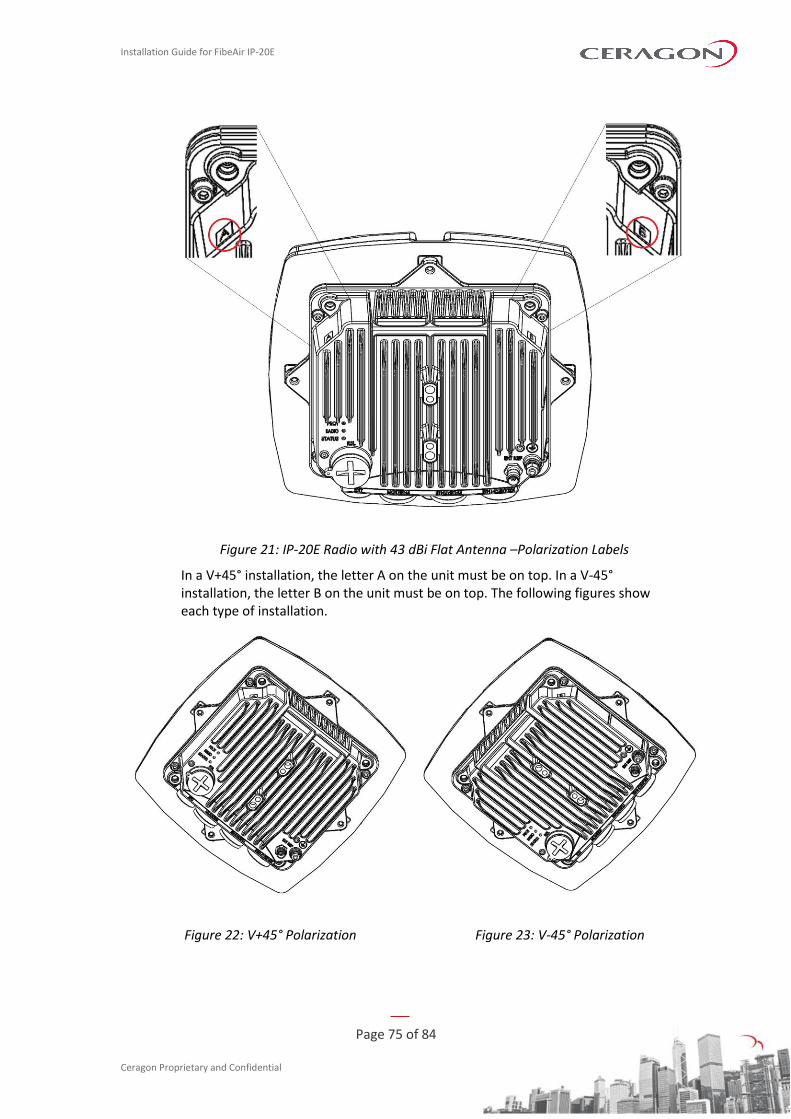
Figure 21: IP-20E Radio with 43 dBi Flat Antenna –Polarization Labels
In a V+45° installation, the letter A on the unit must be on top. In a V-45° installation, the letter B on the unit must be on top. The following figures show each type of installation.
Figure 22: V+45° Polarization Figure 23: V-45° Polarization
Installation Guide for FibeAir IP-20E
Page 76 of 84
Ceragon Proprietary and Confidential
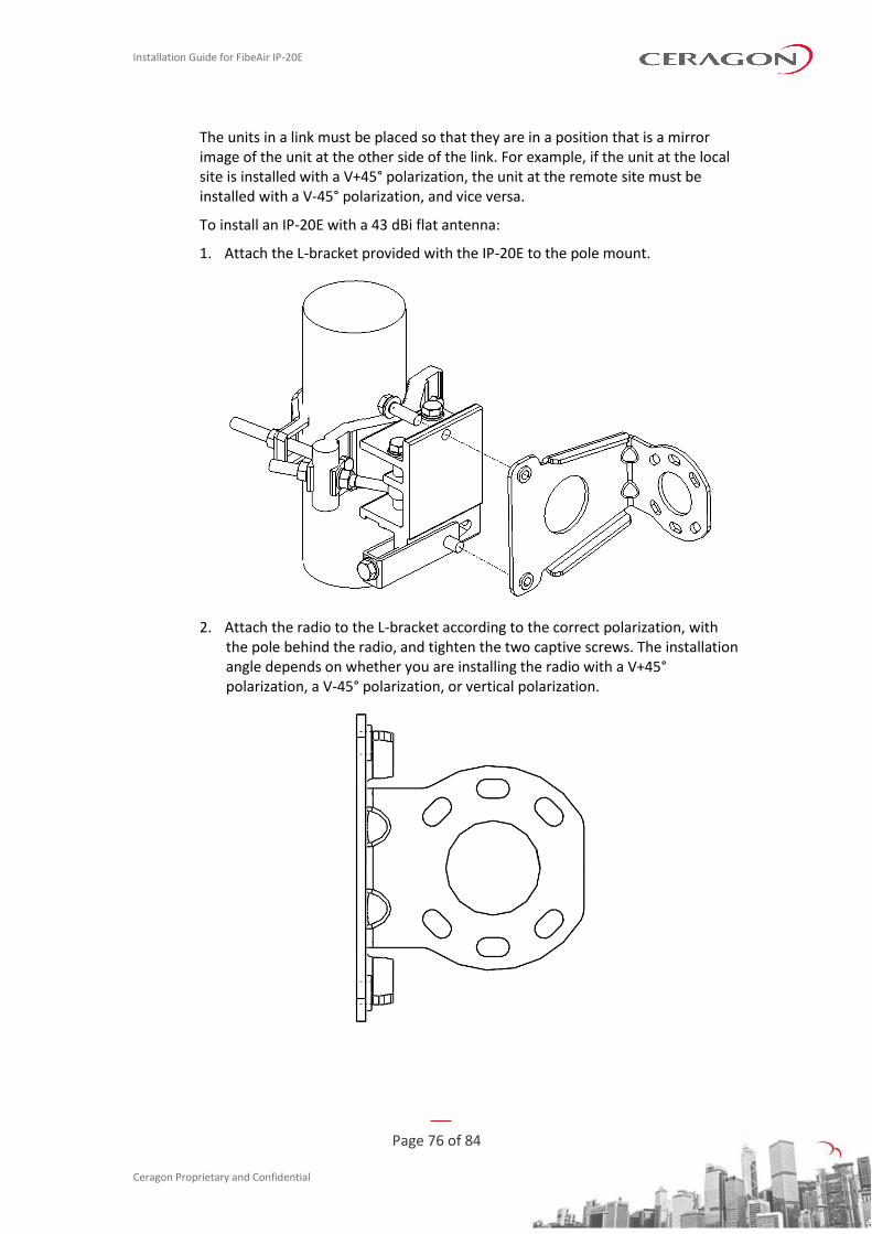
The units in a link must be placed so that they are in a position that is a mirror image of the unit at the other side of the link. For example, if the unit at the local site is installed with a V+45° polarization, the unit at the remote site must be installed with a V-45° polarization, and vice versa.
To install an IP-20E with a 43 dBi flat antenna:
1. Attach the L-bracket provided with the IP-20E to the pole mount.
2. Attach the radio to the L-bracket according to the correct polarization, with the pole behind the radio, and tighten the two captive screws. The installation angle depends on whether you are installing the radio with a V+45° polarization, a V-45° polarization, or vertical polarization.
Installation Guide for FibeAir IP-20E
Page 77 of 84
Ceragon Proprietary and Confidential
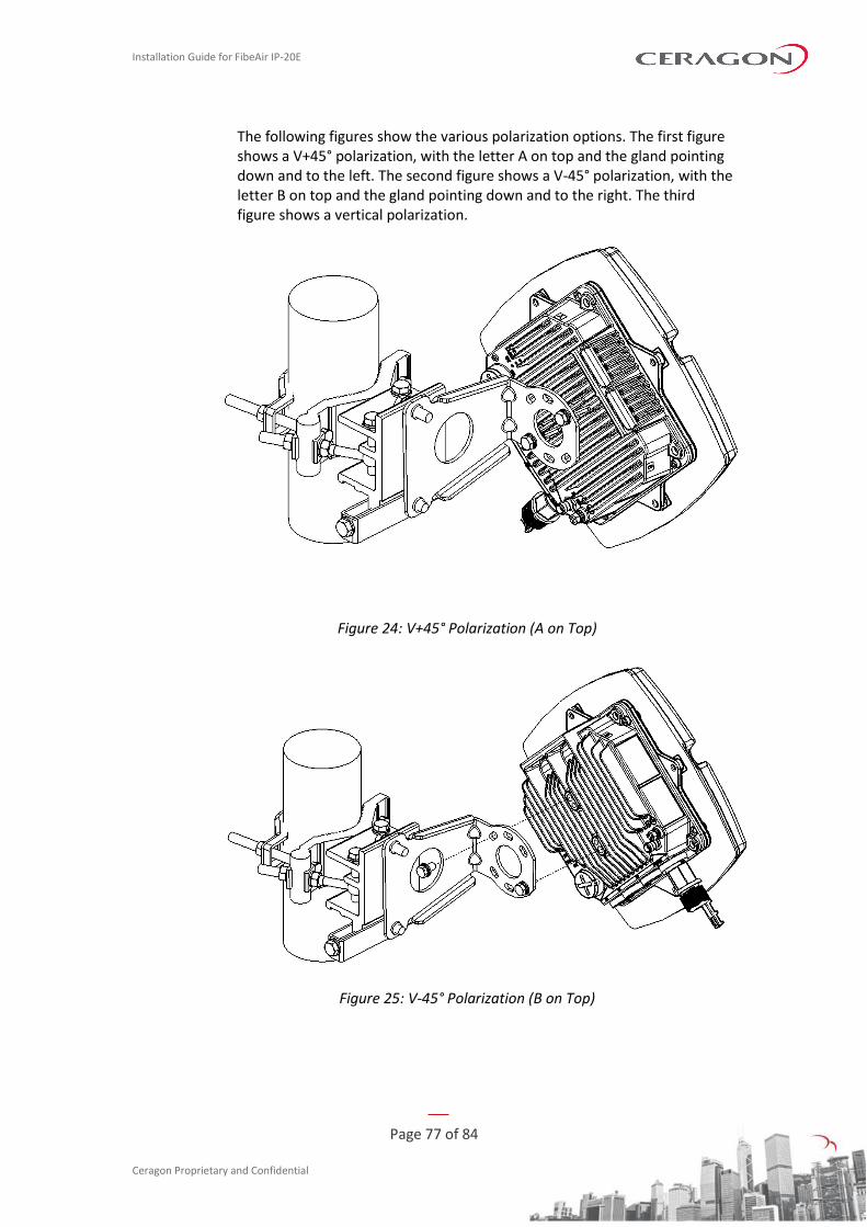
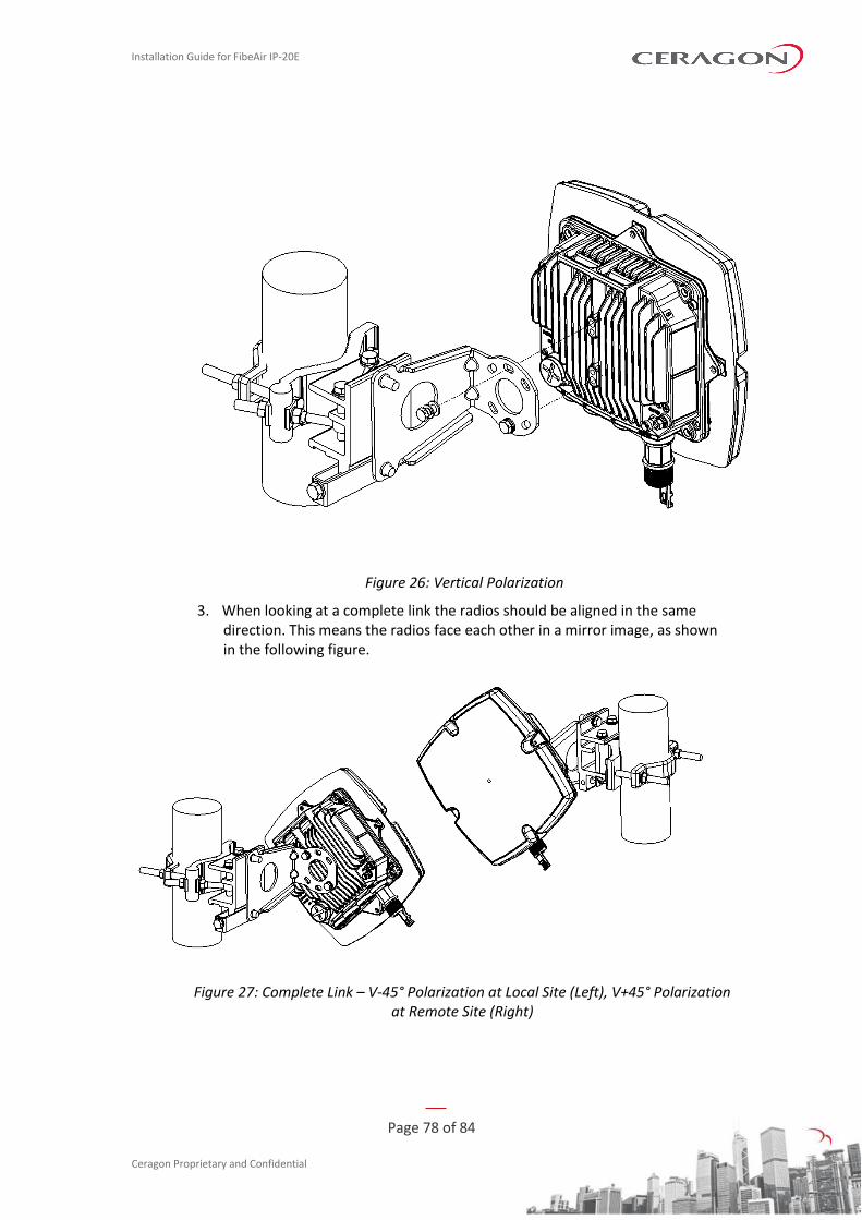
The following figures show the various polarization options. The first figure shows a V+45° polarization, with the letter A on top and the gland pointing down and to the left. The second figure shows a V-45° polarization, with the letter B on top and the gland pointing down and to the right. The third figure shows a vertical polarization.
Figure 24: V+45° Polarization (A on Top)
Figure 25: V-45° Polarization (B on Top)
Installation Guide for FibeAir IP-20E
Page 78 of 84
Ceragon Proprietary and Confidential
Figure 26: Vertical Polarization
3. When looking at a complete link the radios should be aligned in the same direction. This means the radios face each other in a mirror image, as shown in the following figure.
Figure 27: Complete Link – V-45° Polarization at Local Site (Left), V+45° Polarization at Remote Site (Right)
Installation Guide for FibeAir IP-20E
Page 79 of 84
Ceragon Proprietary and Confidential
6.3 2+0 Single Polarization
List of Items
Item Description Quantity Remarks
1 IP-20E Radio 2
2 IP-20E Coupler kit 1 For 2+0 SP configurations, use a
splitter.
3 RFU-C Twist Kit 1
Required Tools
The following tools are required for the installation:
• Metric offset hexagon key wrench #6
• Phillips #2 screwdriver
• Metric offset hexagon key wrench #2.5 and #3
Procedure
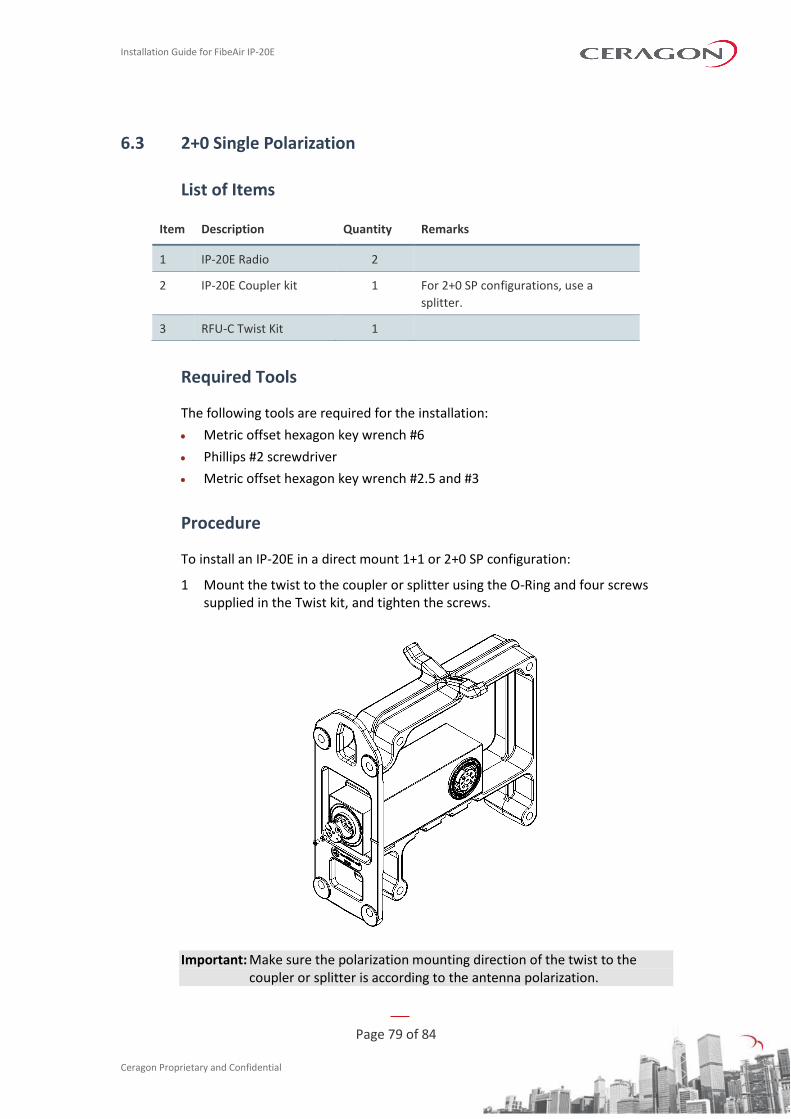
To install an IP-20E in a direct mount 1+1 or 2+0 SP configuration:
1 Mount the twist to the coupler or splitter using the O-Ring and four screws supplied in the Twist kit, and tighten the screws.
Important: Make sure the polarization mounting direction of the twist to the coupler or splitter is according to the antenna polarization.
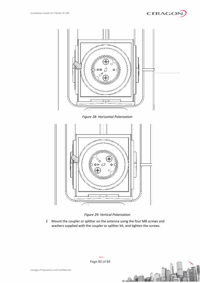
Installation Guide for FibeAir IP-20E
Page 80 of 84
Ceragon Proprietary and Confidential
Figure 28: Horizontal Polarization
Figure 29: Vertical Polarization
2 Mount the coupler or splitter on the antenna using the four M8 screws and washers supplied with the coupler or splitter kit, and tighten the screws.
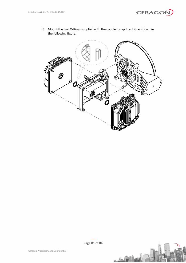
Installation Guide for FibeAir IP-20E
Page 81 of 84
Ceragon Proprietary and Confidential
3 Mount the two O-Rings supplied with the coupler or splitter kit, as shown in the following figure.
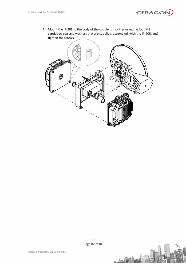
Installation Guide for FibeAir IP-20E
Page 82 of 84
Ceragon Proprietary and Confidential
4 Mount the IP-20E to the body of the coupler or splitter using the four M8 captive screws and washers that are supplied, assembled, with the IP-20E, and tighten the screws.
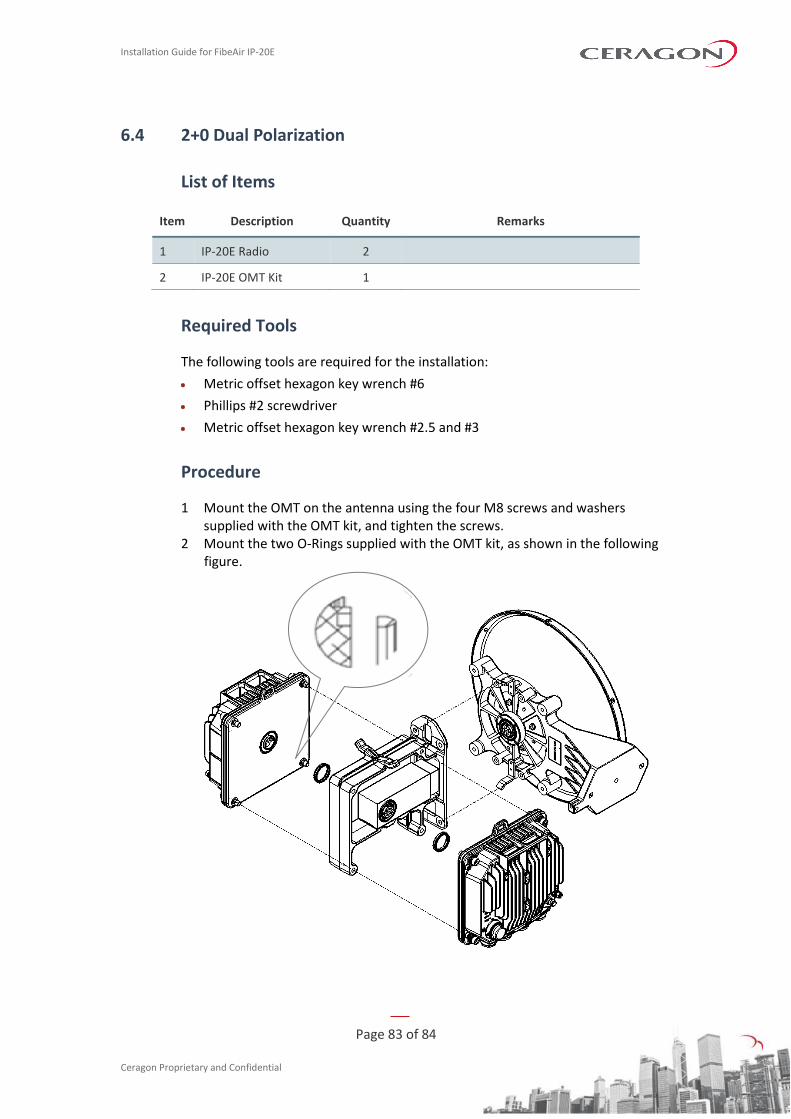
Installation Guide for FibeAir IP-20E
Page 83 of 84
Ceragon Proprietary and Confidential
6.4 2+0 Dual Polarization
List of Items
Item Description Quantity Remarks
1 IP-20E Radio 2
2 IP-20E OMT Kit 1
Required Tools
The following tools are required for the installation:
• Metric offset hexagon key wrench #6
• Phillips #2 screwdriver
• Metric offset hexagon key wrench #2.5 and #3
Procedure
1 Mount the OMT on the antenna using the four M8 screws and washers supplied with the OMT kit, and tighten the screws.
2 Mount the two O-Rings supplied with the OMT kit, as shown in the following figure.
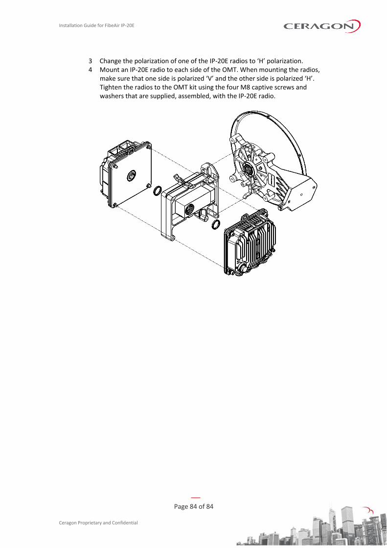
Installation Guide for FibeAir IP-20E
Page 84 of 84
Ceragon Proprietary and Confidential
3 Change the polarization of one of the IP-20E radios to ‘H’ polarization. 4 Mount an IP-20E radio to each side of the OMT. When mounting the radios,
make sure that one side is polarized ‘V’ and the other side is polarized ‘H’. Tighten the radios to the OMT kit using the four M8 captive screws and washers that are supplied, assembled, with the IP-20E radio.