Embed Size (px)
Citation preview

© 2002 American Honda Motor Co., Inc - All Rights Reserved. AII 24046 (0208) 1 of 2008B23-SDA-1000-9A
INSTALLATIONINSTRUCTIONS
Accessory Application Publications No.
Issue Date
AUG 2002
ACCORD4-DOOR
AII 24046in-VEHICLEENTERTAINMENT SYSTEM
(WITH MOONROOF)
Attachment KitP/N 08B23-SDA-100A
i-VES harness
Subharness
DIN Harness
Room light gasket
Template
Monitor bracket
5 Square-neck bolts
5 Flange nuts, 4 mm
16 Wire ties
Wire ties with clip
6 Cushion tapes
Room light harness
2 Washer-screws, 5 x 16 mm
2 Washer-screws, 5 x 25 mm


© 2002 American Honda Motor Co., Inc - All Rights Reserved. AII 24046 (0208) 3 of 20
TOOLS AND SUPPLIES REQUIRED
Phillips screwdriver
Flat-tip screwdriver
10 mm Combination wrench
Ratchet
7 mm, 10 mm and 12 mm Socket
Torque wrench
Utility knife
File
Isopropyl alcohol
Masking tape
Piece of steel wire
Shop towel
Electrical tape
Scissors
Hook tool
Illustration of the components installed on the car
Bus cable(Not used)
2 Latches
6 Flange nuts, 6 mm
2 Washer-bolt, 6 x 16 mm
2 Self-tapping screws, 4 x 8 mm
2 Grommet screws
2 Wire ties
EPT sealer2326010T
ROOM LIGHTHARNESS
MONITORCONSOLE
FMMODULATOR
DVDPLAYER
i-VESHARNESS
DINHARNESS
INSTALLATION
Customer Information: The information in thisinstallation instruction is intended for use only byskilled technicians who have the proper tools,equipment, and training to correctly and safely addequipment to your car. These procedures should notbe attempted by “do-it-yourselfers.”
1. Make sure you have the anti-theft code for theradio, then write down the frequencies for thepreset buttons.
2. Disconnect the negative cable from the battery.
SUBHARNESS

4 of 20 AII 24046 (0208) © 2002 American Honda Motor Co., Inc - All Rights Reserved.
3. Using the Scissors, cut out the marked areasfrom the template along the lines.
4. Position the template on the headliner with theround cutout over the plug and the front edgeagainst the sunroof opening. Tape the template tothe headliner using strips of masking tape.
5. Using the felt-tip pen, mark the headliner alongthe edges of the square cutout in the template.Using the utility knife, cut out the marked areas ofthe headliner.
6. Reaching through the opening you just made inthe headliner, mark the vehicle frame at thecenter line of the template.
8. Using scissors, cut out the marked area from thetemplate, then align the center line of the templatewith the mark you made in step 6. Tape thetemplate to the headliner again.
9. Using the felt-tip pen, mark the headliner aroundthe edges of the template where you just cut.
10. Using the utility knife, cut out the marked area ofthe headliner. Remove the template.
7. Remove the template from the headliner.
2326040T
CENTER LINE(Align with the markmade in step 6.)
TEMPLATE
TEMPLATE
Cut out the area ofthe template.
2326050T
TEMPLATE
Cut out the area. HEADLINER
UTILITYKNIFE
FELT-TIP PEN
2326021T
TEMPLATE
MASKING TAPECut outthe area. UTILITY
KNIFE
FELT-TIPPEN
TEMPLATE
Cut out the areas.
HEADLINER
2326030T
TEMPLATE(Remove.)
VEHICLE FRAME(Mark the frame atthe center line ofthe template.)
FELT-TIP PEN

© 2002 American Honda Motor Co., Inc - All Rights Reserved. AII 24046 (0208) 5 of 20
11. Remove the trim ring.
M/T Model
• Squeeze the plastic clip and pull down on theshift boot. Remove the shift knob by turning itcounterclockwise.
• Gentry pry up on the trim ring to release thesix clips.
• Unplug the two seat heater connectors (ifequipped), and remove the trim ring.
A/T Model
• Gentry pry up on the trim ring to release thesix clips
• Unplug the two seat heater connectors (ifequipped), and remove the trim ring.
12. Remove the dashboard center holder:
• Open the coin pocket lid and remove the coinpocket.
• Remove the two self-tapping screws.
• Gently pull out on the dashboard center holderto release the two retaining clips, unplug thevehicle connector, and remove the centerholder.
2206112K
CLIPS (4)CLIPS (2)
TRIMRING
SEAT HEATERCONNECTOR(If equipped.)
2206061K
COINPOCKET
DASHBOARDCENTERHOLDER
SELF-TAPPINGSCREW(Reuse.)
CLIPS (2)
VEHICLEHARNESS
LID
2206041K
CLIP (4) CLIP (2)
TRIMRING
SEAT HEATERCONNECTOR(If equipped.)
2206031K
SHIFTKNOB
PLASTICCLIP
SHIFTBOOT
TRIMRING

6 of 20 AII 24046 (0208) © 2002 American Honda Motor Co., Inc - All Rights Reserved.
With Ashtray
• Open lid and remove the ashtray.
• Remove the two self-tapping screws.
• Gently pull out on the two retaining clips,unplug the cigarette lighter harness connector,vehicle connector, illumination bulb ,andremove the center holder.
13. Remove the pocket:
• Apply masking tape to the edge of the centerpanel.
• Remove the two self-tapping screws.
• Push in on the bottom of the lid, then pull outon the top by inserting the end of a hook toolbetween the pocket and center panel, andpulling it to out toward you to release the tworetaining clips.
14. Remove the right and left inner covers (one hookand one clip for each cover).
2206073K
RETAININGCLIPS (2)
SELF-TAPPINGSCREW(Reuse.)
HOOK TOOL
CENTER PANEL
LID
Push
MASKINGTAPE
CLIP
LEFT INNERCOVER
HOOK POCKETOPENING
RIGHT INNERCOVER
2226010K
2730010K
SELF-TAPPINGSCREW (Reuse.)
ASHTRAY
DASHBOARDCENTERHOLDER
ILLUMINATIONBULB
CIGARETTELIGHTERHARNESSCONNECTOR
VEHICLECONNECTOR
RETAININGCLIPS (2)

© 2002 American Honda Motor Co., Inc - All Rights Reserved. AII 24046 (0208) 7 of 20
• Using a hook tool, reach inside the vent andlocate the small opening on each side. Gentlypull out on the dash to release the eight clips.
• Remove the center dashboard upper cover byremoving the two vehicle clips and unpluggingthe vehicle connector(s).
16. Remove the center panel (two bolts, three self-tapping screws, and pull the center panel outtoward you to release the five clips).
2506030T
SELF-TAPPINGSCREW
BOLTCLIPS (5)
CENTERPANEL
15. Remove the center dashboard upper cover.
• Carefully insert a flat-tip screwdriver wrappedwith protective tape into the slots on both sidesof the upper cover, then pull out each side ofthe panel back to detach the clips.
• Push the hazard warning switch bottom.Carefully insert a flat-tip screwdriver into theslot at the bottom, then pry up the middleportion of upper panel by releasing the centerclip.
2730030T
CENTER DASHBOARDUPPER COVER
FLAT-TIPSCREWDRIVER
CLIPS (2)
2730040T
FLAT-TIPSCREWDRIVER
CLIPCENTERDASHBOARDUPPER COVER
HAZARDSWITCH
2206083K
CLIPS (8)
CENTERDASHBOARDUPPERCOVER
VEHICLECLIPS (2)
VEHICLECONNECTOR
HOOK TOOL
Pull

8 of 20 AII 24046 (0208) © 2002 American Honda Motor Co., Inc - All Rights Reserved.
17. Remove the driver’s dashboard lower cover.
• Remove one self-tapping screw.
• Release the four clips on the left side first bygently pulling out on the driver’s dashboardlower cover.
• After releasing the four clips, insert the tip ofthe screwdriver between the clip and thedashboard frame. Gently twist the screwdriverto release each clip.
• Unplug the vehicle connector, and remove thelower cover.
19. Pry up on the four retaining tabs that fasten thecap to the left front door sill and remove the cap.
20. Remove the self-tapping screw. Insert the ignitionkey into the key cylinder and turn it clockwise untilit will no longer turn. Using a flat-tip screwdriver,pry up on the key cylinder and remove it from theleft front door sill.
21. Remove the left front door sill (five clips and tworetaining tabs).
2131010T
CLIPS (5)
LEFT FRONTDOOR SILL
FRONT
RETAININGTABS (2)
2131020T
IGNITIONKEY
SELF-TAPPINGSCREW
CAP
RETAININGTABS (4)
KEYCYLINDER
LEFT FRONTDOOR SILL
18. If equipped, remove the driver’s dashboard undercover (release the three retaining clips, one pinand one holder).
2705440T
RETAININGCLIPS (3)
DRIVER’SDASHBOARDUNDER COVER
PIN
HOLDER
2206121K
VEHICLECONNECTOR
SELF-TAPPINGSCREW
CLIPS (7)
DRIVER’SDASHBOARDLOWER COVER
CLIP
CLIP(Releasetheseclips first.)

© 2002 American Honda Motor Co., Inc - All Rights Reserved. AII 24046 (0208) 9 of 20
24. Remove the left center pillar lower anchor bolt.
23. Release the center pillar upper anchor cover(three tabs). Remove the left center pillar upperanchor bolt.
22. Remove the left rear door sill (four clips).
2326060T
LEFT REARDOOR SILL
CLIPS (4)
FRONT
2319030M
LEFT CENTERPILLAR UPPERANCHOR COVER
LEFT CENTERPILLAR UPPERANCHOR BOLT
25. Remove the center pillar weatherstrip. Pull the leftcenter pillar lower trim and left center pillar uppertrim out toward you to release the four clips, andremove the upper and lower trims.
26. Remove the weatherstrip. Pull the left front pillartrim out toward you to release the two clips, andremove the left front pillar trim.
With SRS System Shown
2326070T
CLIPS (4) LEFT CENTERPILLAR UPPER TRIM
FRONT
CENTER PILLARWEATHERSTRIP
CENTER PILLARLOWER ANCHORBOLT
LEFT CENTERPILLAR LOWERTRIM
CENTER PILLARWEATHERSTRIP
2304071M
CLIP(Remove.)
CLIPS (2)
LEFT FRONTPILLAR TRIM
WEATHERSTRIP

10 of 20 AII 24046 (0208) © 2002 American Honda Motor Co., Inc - All Rights Reserved.
27. Remove the left and right lens from roof console(four retaining tabs).
2304010M
ROOFCONSOLE
RIGHT LENS
RETAININGTABS (4)RETAINING
TABS (4)
LEFT LENS
28. Remove the four bolts that fasten the roofconsole. Remove the roof console by pulling it outtoward you, and unplugging the two vehicleconnectors.
29. Remove the cap from the left sunvisor (fourretaining tabs).
30. Remove the left sunvisor (two T25 torx screws,and unplug the connector).
31. Remove the two caps from the left front grab rail,and remove the grab rail (two bolts).
2301011M
VEHICLECONNECTOR
ROOFCONSOLE
BOLT
2326080T
VEHICLECONNECTOR
RETAININGTABS (4)
CAP
LEFTSUNVISOR
TORX SCREW
2326090T
CAP
LEFT FRONTGRAB RAIL
BOLT

© 2002 American Honda Motor Co., Inc - All Rights Reserved. AII 24046 (0208) 11 of 20
2326192T
34. Continue routing the 90° end of the i-VES harnessfrom the dashboard lower cover opening to thepocket opening on the driver’s seat side.
DASHBOARD LOWERCOVER OPENING
i-VESHARNESS
POCKETOPENING
32. Remove the two caps from the left rear grab rail,and remove the grab rail (two bolts).
2326100T
CAP
LEFT REARGRAB RAIL
BOLT
90°TERMINALEND
Routing the i-VES Harness/Monitor Harness andInstalling the Monitor Console
33. Route the 90° end of the i-VES harness from theleft front pillar trim opening to the dashboardlower cover opening.
2326202T
i-VES HARNESS
LEFT FRONTPILLAR TRIMOPENING
i-VESHARNESS
90°TERMINALEND
DASHBOARDLOWER COVEROPENING
35. Remove the sunvisor holders. Using a flat-tipscrewdriver, push the hook, and turn the holder90°, then pull it out.
2326210T
SUNVISORHOLDERS (2)
FLAT-TIPSCREWDRIVER

12 of 20 AII 24046 (0208) © 2002 American Honda Motor Co., Inc - All Rights Reserved.
36. Route the i-VES harness up along the front pillarand under the headliner along side the vehicleharness as shown.
2326221T
VEHICLEHARNESS
HEADLINER
i-VESHARNESS
38. Release the rear interior light.
• Remove the lens (four retaining clips).
• Remove the two screws, lift out the light,unplug the connector, and remove the light.
37. Continue routing the i-VES harness to the rearalong the vehicle harness, and out of headlineropening you made, so that the distance betweenthe headliner opening and i -VES harnessterminal end is 370 mm.
2326231T
VEHICLEHARNESS
HEADLINEROPENING
i-VESHARNESS
370 mm
41. Wrap the end of the steel wire around the roomlight harness connector and secure with anelectrical tape. Pull the room light harness upthrough the rear interior light opening and outthrough the headliner opening.
39. Remove the headliner clip by turning it 90°counterclockwise.
40. Route a piece of steel wire through the hole in therear interior light opening and out through thecutout made in the headliner.
2326250T
REAR INTERIORLIGHT OPENING ELECTRICAL TAPE HEADLINER
OPENING
ROOM LIGHTHARNESS
PIECE OF STEEL WIRE(Wrap the end around theterminal end of the roomlight harness and pull it up.)
BRACKET
2326240T
CLIP(Turn 90°counterclockwiseto remove.)
VEHICLE CONNECTOR
FRONT
INTERIORLIGHT
SCREWLENS

© 2002 American Honda Motor Co., Inc - All Rights Reserved. AII 24046 (0208) 13 of 20
46. Install one collar over each square-neck bolt (usea small piece of masking tape to hold the collars),and install the monitor bracket and the 4 mmflange nuts.
43. Using isopropyl alcohol, thoroughly clean the areawhere the two cushion tapes will attach. Securethe room light harness to the headliner with thetwo cushion tapes in the areas shown.
44. Reinstall the rear room light.
2326260T
VEHICLE 3-PINCONNECTOR
ROOM LIGHTHARNESS 3-PINCONNECTOR
MONITORHARNESS
CUSHIONTAPE
REARINTERIORLIGHT
ROOM LIGHTHARNESS 3-PINCONNECTOR
42. Plug the room light harness 3-pin connectors inbetween the rear interior light and vehicle 3-pinconnectors.
45. Slide the five square-neck bolts into the holes inthe vehicle frame from the top down, Use strips ofmasking tape to hold the bolts in position. Do notremove the clip.
2326270T
SQUARE-NECKBOLTS (5)
VEHICLE FRAME
FRONT
MASKING TAPE
SQUARE-NECK BOLT
CLIP(Do notremovetheclip.)
2326282T
SQUARE-NECKBOLTS (5)
MONITORBRACKET 4 mm FLANGE NUTS (5)
47. Remove the left and the right lenses from themonitor console, then install the monitor gasketon the console.
2326290T
LEFT LENS
RIGHTLENS
MONITORCONSOLE
MONITORGASKET
14 of 20 AII 24046 (0208) © 2002 American Honda Motor Co., Inc - All Rights Reserved.
2326322T
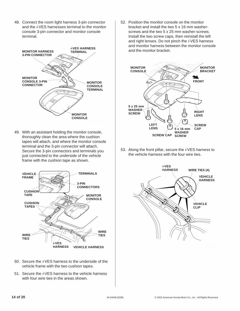
48. Connect the room light harness 3-pin connectorand the i-VES harnesses terminal to the monitorconsole 3-pin connector and monitor consoleterminal.
50. Secure the i-VES harness to the underside of thevehicle frame with the two cushion tapes.
51. Secure the i-VES harness to the vehicle harnesswith four wire ties in the areas shown.
52. Position the monitor console on the monitorbracket and install the two 5 x 16 mm washer-screws and the two 5 x 25 mm washer-screws.Install the two screw caps, then reinstall the leftand right lenses. Do not pinch the i-VES harnessand monitor harness between the monitor consoleand the monitor bracket.
49. With an assistant holding the monitor console,thoroughly clean the area where the cushiontapes will attach, and where the monitor consoleterminal and the 3-pin connector will attach.Secure the 3-pin connectors and terminals youjust connected to the underside of the vehicleframe with the cushion tape as shown.
RIGHTLENS
LEFTLENS
MONITORBRACKET
MONITORCONSOLE
FRONT
5 x 16 mmWASHERSCREW
SCREWCAP
SCREW CAP
5 x 25 mmWASHERSCREW
53. Along the front pillar, secure the i-VES harness tothe vehicle harness with the four wire ties.
2306042M
VEHICLEHARNESS
WIRE TIES (4)i-VESHARNESS
VEHICLECLIP
2326300T
i-VES HARNESSTERMINAL
MONITORCONSOLETERMINAL
MONITOR HARNESS3-PIN CONNECTOR
MONITORCONSOLE 3-PINCONNECTOR
MONITORCONSOLE
2326311T
CUSHIONTAPE MONITOR
CONSOLE
WIRETIES
VEHICLE HARNESS
WIRETIES
i-VESHARNESS
CUSHIONTAPES
VEHICLEFRAME
TERMINALS
3-PINCONNECTORS

© 2002 American Honda Motor Co., Inc - All Rights Reserved. AII 24046 (0208) 15 of 20
55. Continue securing the i-VES harness to thevehicle harness with three wire ties as shown.
2326340T
i-VESHARNESS WIRE TIE
VEHICLEHARNESS
54. Near the fuse box by the dashboard lower coveropening, secure the i-VES harness to the vehicleharness with three wire ties in the areas shown.
2326330T
FUSE BOX
VEHICLEHARNESS
WIRE TIE
i-VESHARNESS
WIRE TIE
VEHICLEHARNESS
With day/night mirror
2306052M
VEHICLEHARNESS
WIRE TIES (4)i-VESHARNESS
i-VESHARNESS
LEFTFRONTPILLAR
DAY/NIGHTMIRRORHARNESS
VEHICLECLIP
VEHICLEHARNESS
Installing the DVD Player
56. Unplug the vehicle 20-pin connector from theaudio unit or the navigation unit. Route the subharness as shown, and plug the subharness 20-pin connector into the vehicle 20-pin connector.
57. Using isopropyl alcohol on a shop towel, clean thearea where the cushion tape will attach. Attachthe cushion tape to the vehicle frame, and securethe connected 20-pin connectors to the vehicleframe with one wire tie.
2326352T
WIRETIE
VEHICLE20-PINCONNECTOR
SUBHARNESS20-PINCONNECTOR
SUBHARNESS
AUDIO UNIT OR NAVIGATION UNIT
SUBHARNESS
CUSHION TAPE
20-PINCONNECTORS
VEHICLE FRAME
VEHICLEHARNESS

16 of 20 AII 24046 (0208) © 2002 American Honda Motor Co., Inc - All Rights Reserved.
59. Remove the vehicle harness clip, and pull it outtoward you.
58. Route the other end of the subharness behindnavigation unit or audio unit, and plug thesubharness 20-pin connector into the rear of thenavigation unit or the audio unit, then reinstall thecenter panel. On navigation equipped vehicle,place the subharness connector between thevehicle bracket and air duct.
With Navigation System
2326361T
SUBHARNESS20-PINCONNECTOR
NAVIGATIONUNIT
CENTER PANEL
2530270T
PLAYERBASE-BRACKET
VEHICLEFRAME
VEHICLEFRAME
6 mmFLANGENUT
VEHICLE HARNESS CLIP(Remove.)
Without Navigation System
2326371T
SUBHARNESS20-PINCONNECTOR
AUDIO UNIT
CENTER PANEL
62. Plug the 90° DIN harness terminal into the FMmodulator (Not the i -VES harness).
60. Install the player base-bracket to the vehicleframe, then install the two 6 mm flange nuts whileholding the bracket firmly against the vehicleframe.
61. Position the FM modulator on the player base-bracket and install the 5 x 8 mm washer-screw.
2326382T
90° DINHARNESSTERMINAL
FMMODULATOR
DIN HARNESS
FMMODULATORANTENNALEAD
5 x 8 mmWASHER-SCREW
PLAYER BASE-BRACKET

© 2002 American Honda Motor Co., Inc - All Rights Reserved. AII 24046 (0208) 17 of 20
2326402T
65. Install the left and right player subbrackets intothe holes in vehicle frame, then install the two 6mm flange nuts while pushing the player sub-bracket upward.
66. Align the end of the i -VES terminal with the endof the DIN harness terminal as shown, and loopthe harnesses, and secure them with two wireties.
67. To protect the center panel, attach the maskingtape to the center panel in the area shown.
2506010T
MASKINGTAPE
CENTER PANEL
63. On the right of the dashboard opening, unplug thevehicle antenna leads and plug into the FMmodulator antenna lead. Plug the FM modulatorantenna lead into the vehicle antenna lead.
WIRE TIE
VEHICLEHARNESS
WIRE TIE
i-VESHARNESS
DIN HARNESS
64. Wrap the FM modulator antenna lead and vehicleharness you removed with one wire tie with clip,and push the wire tie with clip into the hole in theplayer base-bracket.
2326391T
PLAYER BASE-BRACKET
FMMODULATORANTENNALEAD
VEHICLEANTENNALEAD
VEHICLEANTENNALEAD
WIRE TIEWITH CLIP
FMMODULATORANTENNALEAD
DASHBOARDOPENING
ANTENNALEADS
VEHICLE HARNESS
2306021T
LEFT PLAYERSUBBRACKET
RIGHT PLAYERSUBBRACKET
6 mmFLANGE NUT
VEHICLE FRAME
VEHICLEFRAME

18 of 20 AII 24046 (0208) © 2002 American Honda Motor Co., Inc - All Rights Reserved.
2529041T
68. Get the pocket. Using a utility knife, cut the twolugs off from the pocket.
LUG(Cut off.)
LUG
69. Install one latch to each to the left and right playerbrackets.
70. Position the DVD player and pocket on the left andright player brackets, and install four 5 x 8 mmwasher-screws, and the two 4 x 8 mm self-tapping screws.
71. Plug the subharness 4-pin connector, the DINharness terminal and the i-VES harness terminalinto the rear of the DVD player (plug the i-VESharness terminal into the yellow label position).
2306031T
LEFT PLAYERBRACKET
PLAYER
LATCH
5 x 8 mmWASHER-SCREWS (4)
4 x 8 mmSELF-TAPPINGSCREW
RIGHTPLAYERBRACKET
4 x 8 mmSELF-TAPPINGSCREW
LATCH
LATCH
LATCH
1 mm1 mm
2326411T
i-VES HARNESSTERMINAL
DVD PLAYER
DIN HARNESSTERMINALSUB HARNESS 4-PIN
CONNECTOR
YELLOWLABEL
72. Install the DVD player to the brackets using four 6mm flange nuts.
2326420T
LEFT PLAYERSUBBRACKET
RIGHT PLAYERSUBBRACKET
DVDPLAYER
6 mmFLANGENUT PLAYER
BASE-BRACKET

© 2002 American Honda Motor Co., Inc - All Rights Reserved. AII 24046 (0208) 19 of 20
76. Insert the player panel clips into latches, andattach the player panel to the instrument panelwith the two self-tapping screws removed in step13. Remove the masking tape.
73. Measure and cut the EPT sealer as shown.
74. Clean the player panel with isopropyl alcoholwhere the EPT sealers will be attached. Attachthe player panel with the EPT sealer, and cut offthe marked area from the player panel.
2612010T
EPT SEALER(Cut off themarked area.)
PLAYERPANEL
8 mm
EPT SEALER
8 mm
75. Attach the two grommet screws to the playerpanel.
2306131T
GROMMETSCREW
PLAYERPANEL
2306141T
SELF TAPPINGSCREW(reused )
LATCH
PLAYERPANEL
CLIP

20 of 20 AII 24046 (0208) © 2002 American Honda Motor Co., Inc - All Rights Reserved.
77. Check that all wire harnesses are routed properlyand all connectors are plugged in.
78. Reconnect the negative cable to the battery.
79. Enter the customer’s radio anti-theft code, andreset the radio station presets.
80. Set the clock.
81. Check the operation of the in-vehicleentertainment system according to the itsOwner’s Manual.
82. Put the in-vehicle entertainment system Owner’sManual in the glove box.
83. Reinstall all removed parts.
• Tighten the seat belt anchor bolts to thespecified torque: 29.4 to 34.3 N·m(3.0 to 3.5 kgf·m, 21 to 25 lbf·ft)
NOTE: Whenever the battery is disconnected, thedriver’s window AUTO function is disabled.
84. Start the engine. Push down fully on the driver’swindow switch until the window is fully open.
85. Pull up fully on the driver’s window switch to closethe window completely, then hold the switch for 2seconds.
86. Test the window AUTO function.