Embed Size (px)
Citation preview

INSTALLATION INSTRlJCTIONS
INTERAV ALTERNATOR
MODEL NO, 1255A
STeSA 334 SW
Island Enterprises
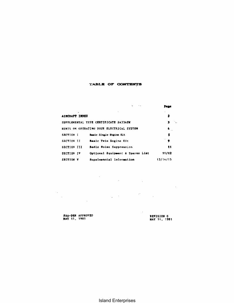
TABLE OF CONTENTS
supn_."HTAL un cUTIfICAT! SAn4SW
HIOTS 0" OPlRA!I"G YOU~ "'CTRICA" SYSHH
sKeTION .... i. Sj~~ """itl< <.it
<ACTIO' " "'de hi" "n,in. '" SECTIO' m ""dlo Ooi •• S"pp •••• !on
SECTIQN " Qptional ~oui_nt • Spar ••
S!OTIO • • 5upplom@"tal 1.!OT_Hon
rAA-&." APPROVlD "AY II, .98.
11 ..
-• , • • • "
11/12
1l/14/1S
REVISION G "AY 11, 1981
Island Enterprises

INDEX
~j AIRCRAFT APPROVED - STC SA334SW - REVISION 16 - JULY 20, 1981
Kit Aircraft Dedgnation
SE B .... ch 23, all s .. ri .. s 5E B .. ech 35, all suies with Continental 0_470/10_470 engines 5£ Beech H35, J35, K35, M35. N3S, 1'35, 35-33, 35_A33, 3S-833. 3S·C]] 5£ Bellanca 14-1 "I, all seriea with Continental 0-470/10-470 engines 5E Ceuna 180, aU "erie~
5E Cessna 182, all "eries SE Ceuna 185, all series
SE Cenna 210, all seri .... SE Ce .. na 210_5, all ~ .. ri .. s SE C .. una 206 Sf: Consolidated Aeronautics Colonial CI, C2. Lake LA-4, all seri .... SE Do",ner (Republic) RC-] SE: H .. lio H2S0 SE Hughe .. 269, all .. e';e~ with belt-driven generato,.. SE Int .. rmountain (C .. llah) A, all .. eries with bell-driv .. n Reneralors SE: Lockh~ed 402_2 SE MeyerB 200, all sedes SE Mooney M20, all "er;e. SE Navion D, E, F. G, and others with 0-470 and 10_470 engines SE Piper PA_I2.. PA_12S, with LJ'cominR 0_290 " .. ,ies .,ngin .. 5£ PiperPA_16 S£ Piper PA-18, all Ber;eS with belt-driven generalOu SE Pip .. , PA_18, all series with belt-driv .. n generators
SE Piper PA-20, all .. eries with belt-driven g .. nerators SE Piper PA-2.Z, all ""ri"5 with b .. lI-driv .. n g .. neutors SE Piper PA-24, 'PA_24_2S0 serle. S£: Pip~r PA_25, all se ..... s SE Pip .. r PA_ZS, all 8eri .. &
SE Piper FA_2B, aU " .. rie .. SE Varga ZI50A, all ... rie .. with wide-d .. ck Lycoming 0-]20 enlllnee
TE c..mair 480 TE Helio 500 TE Pine Air (and) Fie,,' Aiccral1 Ltd. Super-V TE Piper PA_23, all seri .. s TE Pip .. r PA-30
/OJ /~ . FAA Approval Q:7'. .. ~. {fA .... <:("7.A. .. ~_-
~f, "F.nlllln~"ring <, Maflufa~tu,lng BrAnch, ASW-210
Oat.. i l _71,20", •• ,1 __ _ ,
T.C,
!I!!:.-. AICE A_711 lAIS
'" 5 .. 3AJl 3A24
3AZI lA21 A4CE JAJl A-169 lA8 4Hl2 A-158 2AII 3AIB
'M '" A-7BO lAi lAZ AR_7
1M lA6 IA1S
'" 2AIO 2AI] 4AI9
'AZ A2EA 4A29" A IAIO
AlE" .....
Island Enterprises
Report 65-113
...... ,,1bnD '&io 'fIqIartmm If .... patatil. --1rdml g .. sUatalsUlllitll
,5upplcmrntkll 1r~pc Q:mificQtc
!nterAv, In<:. P. O. Iloo< 16714 IOU E. Nakoha
SA334SW
San Antunio, Lexas 782L6
... ,/0~ 4,,/ d... ""'7'" I'A~ {wt- .k"" /~ M<,/-//-",,,'JII'''.t..« ""M /k1.",,/..6~4d ..".....t,,, ......
'i''lh Civil Air
a.~",~/.?e../.,,-/ -. ~}0' r';~""y.'~ .. kv f{.."k ,,' LimitatiDn~ and Conclitiong
,""..I" ,,' Limitations ""' Conditions
j/~/ '" Limitations ,,' Conditions
y:..,.y;.{,;. .. .,..~'9'''''j7n ;'JA .. ,."... InBtallation of lnter/lv Alternator in accordance "ith Report 65-113, Revision G dated S/ll/Sl, Or later FAA or FM DER approved revisions.
See attached Eligibility List dated July 20, 1981, FilII approved, for original type certificate numbers, makes, and mod~l3.
Cmnpatibility of tbis modification "It II othc~ pr~vio""1y approved modification" musl be cl~l~I;lJlin"d by the lllsta11el.
'~~Y-~""" ,."",,a, ~'#'~/'7 d./" "o<i,~ .;, M" 1 ..... ..;,/. W" ,_I d~// "'m_" ,,..,,;../ ""'/,:/~
_,.J,"'-<~n£-< .. ,,,.i~-I,~,,, "'~m_ .. I.-"" L.& .. <.!,,{~_..:.~ ",/.,//",&4/" & .rI"'/'"",.;,/",'/'~.Jd,
Y'~7',.y/'C"':'H Januury 8, 1964
5/~ki.""'nR" Febrllry 3, 1964
, .......... ·' .. '1'"-•• 1
Don P. Watson
10/8/64: 12/8{64; 9/l6/65; 11/14/65; 5/3/66; 10/21{66; 9/15/75; 5/17!79; 5/4/81; 7/20/81
Revision 16
Gh{e-f, Enl!ineerinl! and Nanufacturing Branch
I r,If')
-3-
Island Enterprises

Repor-t 65-113 . ''' ...... - --,
HINTS ON OPERATING YOUR ELECTRICAL SYSTEM
Alternators have different characteristics than DC Generators.Although the InterAv Alternator has several "built-in" safety features to protect its system, no meclumical devices can substitute for Good Operating Practices. To insure that your Alternator system will always render you dependable service, thoroughly familiarize yourself with the warnings listed belOW. See that these warnings are complied with. Failure to comply could result in damage to the electrical system.
DON'T open batterY switch at any time that Alternator is operating.
DON'T operate AlternatOr with battery disconnected at any time
DON'T turn battery switch "ON" when batterY is being charged with battery charger.
DON'T use outside power source to start aircraft unless certain tbat polarity is correct; positive to positive and negative to negative.
DON'T open Alternator circuit breaker at any time when Alternator is operating if manual-type Circuit breaker is used. Leave in "ON" or closed position at all times.
DON'T install battery cables in reverse polarity. Connect positive lead to positive post and negative lead to negative post.
DON'T operate Alternator at any time with Alternator "OUTPUT" lead disconnected.
DON'T ground field terminal at any tiMe Alternator is operating.
NOTE; To .ake Alternator inoperative when checking for radio noise, only the field circuit should be opened. On aircraft that do not have an individual switch for the Alternator field cirCUit (filen.switch), it will be necessary to disconnect the field lead at the Alternator and then run engine. (see Section III)
I
Island Enterprises
6')-113
~tity
1 each
1 each
1 each
1 each
each
2 each
1 each
1 each
1 each
1 each
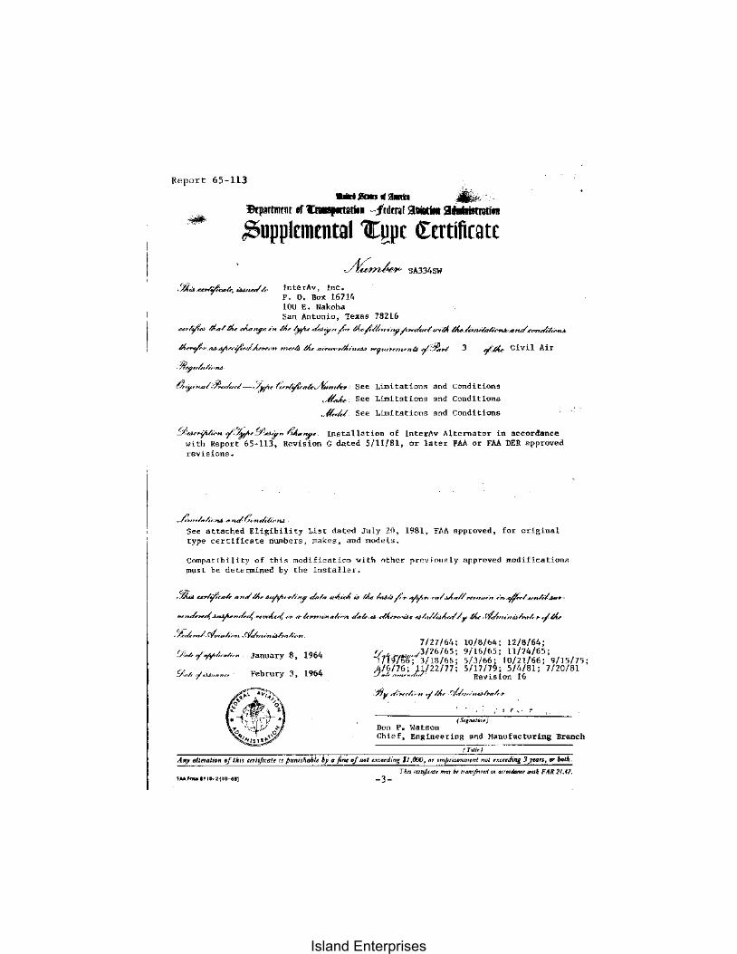
KI1 #SE
SECTION I
ALTERNATOR INSTALLATION BASIC INSTALLATION KIT
Part No_ 015-01236
SLNGLE ENGINE AIRCRAFT
PARTS LIST
Part Reference ",,", Number Description
015-01237 A-IS2A Alternator Assembly
625-61623 A-153D Voltage Regulator
635-62448 OVR-12B Overvoltage Relay
015-01240 A-167D Mounting Bar Assy. Kit
245-23709 A-l78 Spike Guard Capacitor
l65-15041 A-178-2 Clamps
435-42408 A-178-4 Lead Kit
395-37992 A-l7BC Hardware Kit
415-40054 OVR-I2A-6 Placard
R-65-1l3 Installation Instructions
SEE SECTION IV for OPTIONAL EQUlPMENT
Island Enterprises
~~ INTERAV ALTERNATOR INBTALLATYON
KIT eS[
Instructions for Installation I Single E"glne Aircraft
PART J: INSTALLATION OF ALTERNA1l»I. AND REGULATOR
1. Disconnect battery. identify, marl<, and disconn""t origiual wires £rOll Gen. & Reg_
2. Ra.ove Generator and Voltage Regulator.
3. Install Alternatur, Part #{}15-01237, using existing generator mountiJl>( brackets. Install lIounting bar with hardware supplied in kit, Part to15-{}1240. Use AN-97[}-5 wasbers to adjust spacing between generator bracket and bar bracket, If frant hole in bar is utilized, install short AN5H5A bolt with two washers to prevent interference with AN!lhl6A holt.
4. Adjust for proper pulley align.ent and install approved drive belt and adjust belt tension in accordance with st<:lndard procedures. Safety wire bolts together aI> reqtlil"ed and safety AN8H16A bolt around support bar.
5. Inst .. ll Voltage Regulator, Part #625-61623, where origina.l regulator was .ounled. Ched tllat the free end on the bonding strap is well grourtded to the airfrllPll!. Usirut IIardware, clamps and leads, .aunt spike guard capacitor, Part #245-23709 to regulator as shown in the diagraJII.
6. If origiIldl cin,,,il break,n is raled less than 60 allP, rellove and replace with Part 1295-2%94, or equivalent 60 amp circuit breaker. Reconnect wires.
7. Connect the large wire removed from the generator output terminal to the output terminal of the Alternator. AC-43.13-1A, Chapter 11 covers in detail wire size ,·equlfelllents to aec __ udate the 50 amp alternator output.
8. Connect the small wire ra.oved from the generator field terminal to the field ter.inator of the alternator.
9. Install a bonding strap or wire, as large, or larger than, tbe Alternator output wire, fran tbe ground terminal of tbe Alteroator to the eng~ne mount or eogine case. Be sure yo~ have a good ground between the Alternator and the airframe.
10. Justoll au 18 ga. wire from the ground ter.inal of the Alternator to the ground ter.illdl of the Vultage Regulator.
11. Install an 18 gao wire from the Regulotor ten.inal of the Alternator to the Regulator terlllinal of the Volt.agp Regulator.
12. c.onnect t.he original field wire froo the cabin generator field switch to the fi .. ld umain"l uf the Voltage Regulator. Note that this wire was originally attaehed to tlle field t.erlllinal of the old r .. gulator.
13. Splice tbe rellalning two heavy wires which were conoeated to bat. and gen/aOlature tefllinals of the original voltage regulator together using butt or nog type aup ter~ .inals of proper size.
-6-
Island Enterprises
Report 65-113 KIT .,Sf
PART II: INSTALLAT::rON OF OVERVOLTAGE RELAY
1. install Overvoltage Relay, Part No. 61S-62441l. in an area behind instrumf'nt panel which will provide clearance from other electrical component connections and clear of moving parts. Mount to convenient structure using No. 8 SCreWS and nuts.
2. Install a 5 amp trip free circuit breaker such as MS2451O-5 or equivalent.
3. Connect the wire identified as "Red-Pas" from the r!'liIv to the 5 amp circuit breaker.
4. Connect. the wire identified as "Blue--(Jnd" from the relay to a good airframe ground.
5. At the field switch in the aircraft. disconnect the wire ~oin~ to tile AlLernator [ield tprminal and splice onl' of lh" t.wn wirl's idl'ntitied as "Green-fld" to the disconnectt'.d wire.
6. Connect the remaining "Greilll~Fld" wire to the terainal ot the field swilch vacated in Step 5.
7. Install placard, Part No. 415~40054, on instrument panel in view of pilot lIear Alternator field liwitch.
8. Use ring and hutt typ€ t.mnil1'lls and splic{>s such as allIp 32q51 and 321026 for all connections.
9. Insure all wires are properlv secured and work is done in co.pliance with A.C.43.13-1A.
PART III: PREPARATION OF FORM FAA .337
1. Install Alternator in accordance with Suppleillental Type Certiticat(' No. SA334SW. Weight Change: ICompute weight and balance as neces:;,ary). Check size of Wire from Alternator output ter.inal to Aiternato,' drcuit hreaker and from Alternator circuit breaker to buss and s;7.e of AitematOl cireuit breaker with A.C.43.13-1A. (Note: l'nnl;ulle tllili statement. ,,>. appii~ahle. If wire and circuit breaker sizes are satisfactory. lin state. If not 5atisfactorY. statE' win' and/or circuit. breaker size installed to conforlll with A.C.43.13-1A. )
2. Modify dircnl.It e<tuipment list b~ reauval uf generator listed and adding Alternator installation.
WEIGIn': Altcrnator Installation ~~ 11 lbs.
ARM: Refer to Aircraft EquiPilent List.
-7-
Island Enterprises
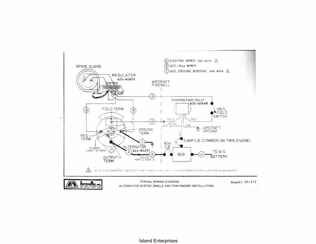
SPIK E GUARD
REG TERM
, L.G.
FIELD TER M ~
@EXISTI NG WIRE S SH NOTE .&. @ADD,18Qo WIRES
© ADD , GRDU ND 80tlDING Sff NOlf .&.
AIRCRll.FT FIREWALL
I
"
ORI G FIELD N IT f'.t-I
A.IRCR AFT GROUND
5 AM PC B (COMMON ON TWIN ENGINE )
BUS TO A/C
.&. AC~J '3 ... Ct1 .... H£~ ;;[( , .1)'1.- ..... 1 ".. ,,"f. '" 11'~'JII~l'WVV""'''1 ~'':B ~O''':.c''-\'POUf~lIr
/t'--.\ I ..... A. ~ .,... u::. .1:M..,-r..f'~ TYPICAL WIRING DI AGRAM
ALTERNATOR SYSTEM, SINGLE AND TWIN ENGINE INSTALLA TION Re port 65- 11 3
Island Enterprises

SECTION II
ALTERNATOR INSTALLATION BASIC INSTALLATION KIT
2 Each .. Part No. 015-01236
TWIN ENGINE AIRCRAFT
PARTS LIST
PM' Reference Quantity Nu..ber NUllber Description
2 each 015·01237 A·l52A Alternator Assembly
2 each 625~61623 A-153D Voltage Regulator
2 each 635-62448 OVR-12B Overvoltage Relay
2 each 015-01240 A-167D Mounting Bar Assy.Kit
2 each 245-23709 A-US Spike Guard Capacitor
4 each 165-15041 A-178-2 Clamps
2 each 435-42408 A-178-4 Lead Kit
2 each 395-37992 A-178C Hardware Kit
each 415-40055 OVR-12A-7 Placard
1 each R-65-113 Installation Instructions
SEE SECTION IV for OPTIONAL EQUIPMENT
Island Enterprises

Report 65-113
PART
ALTERNATOR INSTALLATION
Twin Engine Aircraft
I: INSTALLATION OF ALTERNATOR AND REGULATOR
1. Install Alternato,s and Regulators on each engine in a"cordance with instructions for sin..,;1p pngiop.
2. Remove parallelinA relays and s"curp wire". The Alternator »ystp"' do~s not require paralleling relays.
PART II: INSTALLATION OF OVERVOLTAGE RELAY
1. Tm;ta11 Ovl'rvoltage Relays for each engine in a1:cor<iance with instructions for sltlj1,le .. "gin ...
2. Install placard, rart No. 415-40055, 00 instrument panel in view of pilot near alternator field switch.
PART III: PREPARATION OF FORM FAA337
Install Alternator in accordance with Suppl€lllental Type Certifi~"l .. No.SA334SW. Weight Change: (Coapute weight and balance as necessary. 1 Chl'ck 5izp of wirp from right and left Alternat{]r output tenuina1s to ri>:ht <lnd left Alternator circuit hr"ak"r,; aod from right anri left Alternator circuit breakers to buss and size of right and left ,~lt_ernator circuit breakers with A.C.43.13-1A. jN(JI'E: Continue this statement as applicable. If wire and circuit breaker sizes are satisfactory, so state. H not "atisfactory, state wire and/or circuit hreaker size installed to conform with A.C.43.13-1A.)
WEIGHT: Dual Alternator Installa. wght., 22 Ibs.
ARM: Refer tn Aircraft EqJliPl'"nt List.
K
Island Enterprises
SECTION IXI
RADIO NOISE SUPRESSION TECHNIQUES
The Alternator system has built-in radio noise suppression, and virtually eliminates all noise and interference, on most installations. If additional suppression is required, a qualified Radio Maintenance Technician should be consulted for recommendations.
SECTION IV
OPTIONAL EQUIPMENT AND SPARES LIST
OPTIONAL EQUIPMENT
Req. Po, Part Reference Engine NU/Dber Nur.ber Description
295-2%94 A-l54 Circuit Breaker, 60 SlIp
295-29699 A~200 Circuit Breaker, 5 amp.
015-01246 A-152-3 Fan, Coo lifll/;, fo, opposite rotatiofl eflgine
015-01245 A-179-1 Ara, Bel t Adjust, PA-22
Island Enterprises
REQ.PER ENGINE ******
1
1
1
1
1
1
1
1
2
1
1
1
1
1
2
1
1
1
1
1
1
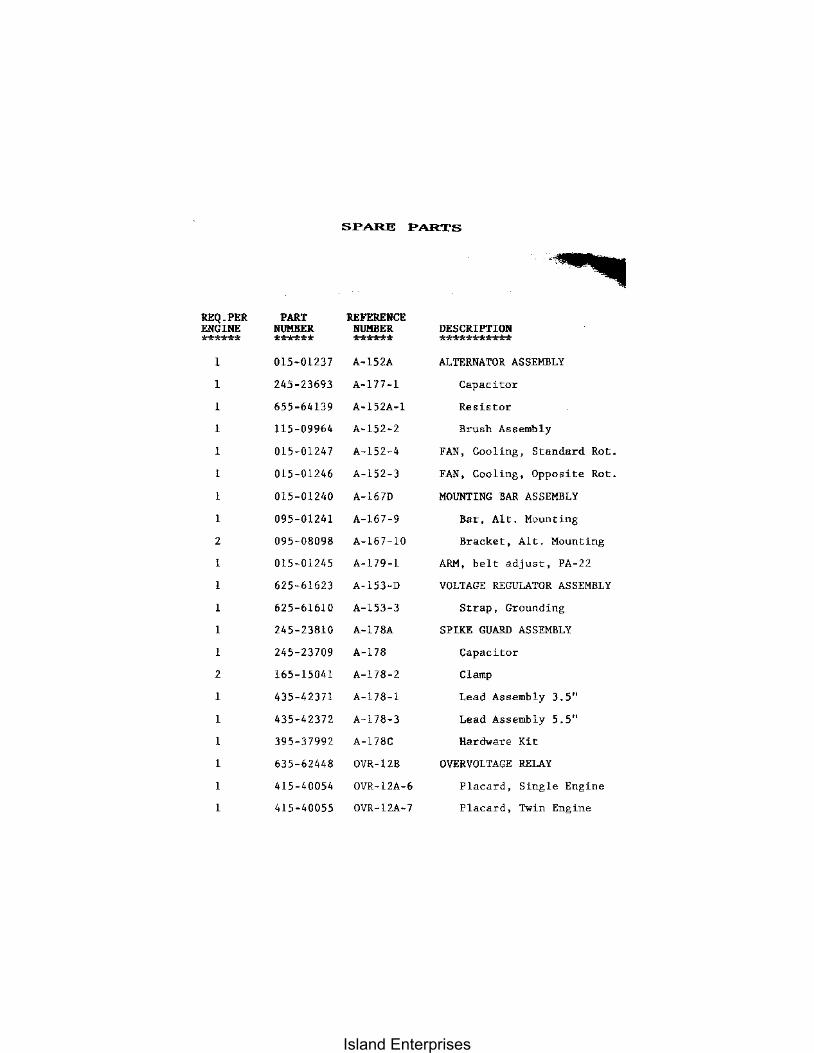
SPARE PARTS
PART REFERENCE NUMBER NUMBER ****** ****** 015-01237 A-lS2A
245-23693 A-177-1
655-64139 A-I52A-l
115-09964 A-152-2
015-01247 A-152-4
015-01246 A-152-3
015-01240 A-167D
095-01241 A-167-9
095-08098 A-167-10
015-01245 A-179-1
625-61623 A-153-D
625-61610 A-153-3
245-23810 A-178A
245-23709 A-178
165-15041 A-178-2
435-42371 A-178-1
435-42372 A-178-3
395-37992 A-178C
635-62448 OVR-12B
415-40054 OVR-12A-6
415-40055 OVR-12A-7
DESCRIPTION *********** ALTERNATOR ASSEMBLY
Capacitor
Resistor
Brush Assembly
FAN, Cooling, Standard Rot.
FAN, Cooling, Opposite Rot.
MOUNTING BAR ASSEMBLY
Bar, Alt. Mounting
Bracket, Alt. Mounting
ARM. belt adjust, PA-22
VOLTAGE REGULATOR ASSEMBLY
Strap, Grounding
SPIKE GUARD ASSEMBLY
Capacitor
Clamp
Lead Assembly 3.5"
Lead Assembly 5.5"
Hardware Kit
OVERVOLTAGE RELAY
Placard, Single Engine
Placard, Twin Engine
Island Enterprises
SECTION V
SUPPLEMENTAL TNFORMATLON
1. Bonanza Aircraft SIN's D4866 through D6162 2. Reverse Rolaling Engines and Fan Rotation 3. Piper PA 24-250 Belt Recommendation$ 4. Lycoming Wide Deck Engines 5. Downer (Republic) RC-3 Seabee, Franklin 6A8-:l15
1. CoJipliance with the following excerpt from Beechcraft Service News Vol. XIII, No.2, Feh. 1950 is recOllOleTlded when an IlIterAv Alternator kit is retrofitted to Bonanza Aircraft.
"SIIOCK ooutfl'm GENERATOR BRACKETS -- A new shock IIOOnted generator bracket "bicb "ill redure vih,·.~tion, th .. _jar causp. of generator aad Ilen~rator hr~"kH failures, has been developed for the C.nnli""ntal O-~70 and 10-470 series eflj{i"e~. The shock ll(Iunted generator brarket is available for installation 011 the Aonanza series o( airplanes, serials D-4866 1I1I0UIVI 1J-6161. In.lallation of this new brackt't "ill b8 .. ad~ at tile factory on ,,11 Moo,,1 33 airc,.aft and 011 Bonanzas, S~rlals D-6162 and aft .. ,.. This impn>YP<i bracket assemhly was d<!Yclopro hy Cnntln~"l"l Motors and is available in Conti!),mtal kit EQ-58~1. Th@ kit coasists at fOllr rulober shock mounts, a new generator bra~e. a n_ .. o"nling brack~t, attach-paris and Installation inSTructions Further infor~atj"n cnncerning Kit EQ-5~41 or the kit il~elf ""'Y be obtain~d br contacting rlw Cnntin~ntal Motors Cor~ora!ion of M(\~k .. go!l. Middgdn. or any authm-ized Continental Disr'-ihutor."
NOTE: The above .entioned kit is no longer available as a kit. but individual parts are currently available fra. Teledyne Continental Motors Distributor or through their custOief service depart.ent in Nobile, Alabaaa.
2. Installation of Alternators on aircraft equipped with Reverse Rotating Engines:
An opposite rotatioll fan. Part NlEber 015-01246, is available fronr the factory on an exchange basis at no charge. Remove the Part No. 015-01247 fan frOUI the Alternator to be installed on the reverse rotation engine and replace witb Part No. 015-01246 Ian.
Island Enterprises
3. Piper PA-24-250 Belt Rec~ndations; Gates Belt PIN's 575TG (31"), 8353 (31-1/8") or 8242 (32-1/8").
4. STC SA334SW was originally approved for installation on those aircraft listed on Page 2 using the "narrow deck" LycOIIing engines. Later versions of sOlIe ain:nlft will have the "Wide deck" LYcoming engine installed. For these engines the standard Haunting Bar Assy. in thp kit is replaced by LYcoming brackets which bolt directly to the engine case, The Alternator requires a special extended pulley and bel t. Installation Olust be accomplished in accordance with Drawing No, ,1,-181.
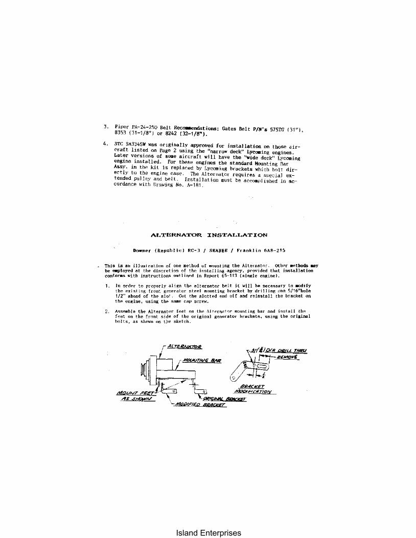
ALTERNATOR INSTALLATION
Downer (Republic) RC-3 I S!AB!E I Franklin 6A8-215
This is all i.llu~l,.al.inn of olle method uf .. ',unting the Altern,:tor. Oth~r ... ~~_r be ..-played at th .. dh~ret ion of til" in"t.all ing agency, prov,ded, that lnsta .. on conforn,. with instructions Q1Itlio"d in Report 65-lt3 (sinde cnglne).
,
In ord .. , to properly all~n til" alternator b~lt It will b .. neeMSary ~o, ::::i~Y the H,.t)n@;frnnt generator ~tp .. 1 .. "anthg bracket by dr,ll,ng ,)n", 1 0 e 1/2'" ahead of the slot Cut the slottpd end pff and reinstall the brllcket on th~ ""lline, using th" sa.me cap Scr~w.
As~~nble the Alternator feet"" t.he AtrHn~t"r ",o"nting bar a~d ;nSlall.t~p I r"ct on the front side of the original gen<>ratoT h,.acket~, USIng the nngllla bolts, as .how" on tI,e sketch.
r AlTE.4WA'7!?R
8.R.4CKET .h1!:xKR.Anoty
tI'jW.gT
Island Enterprises
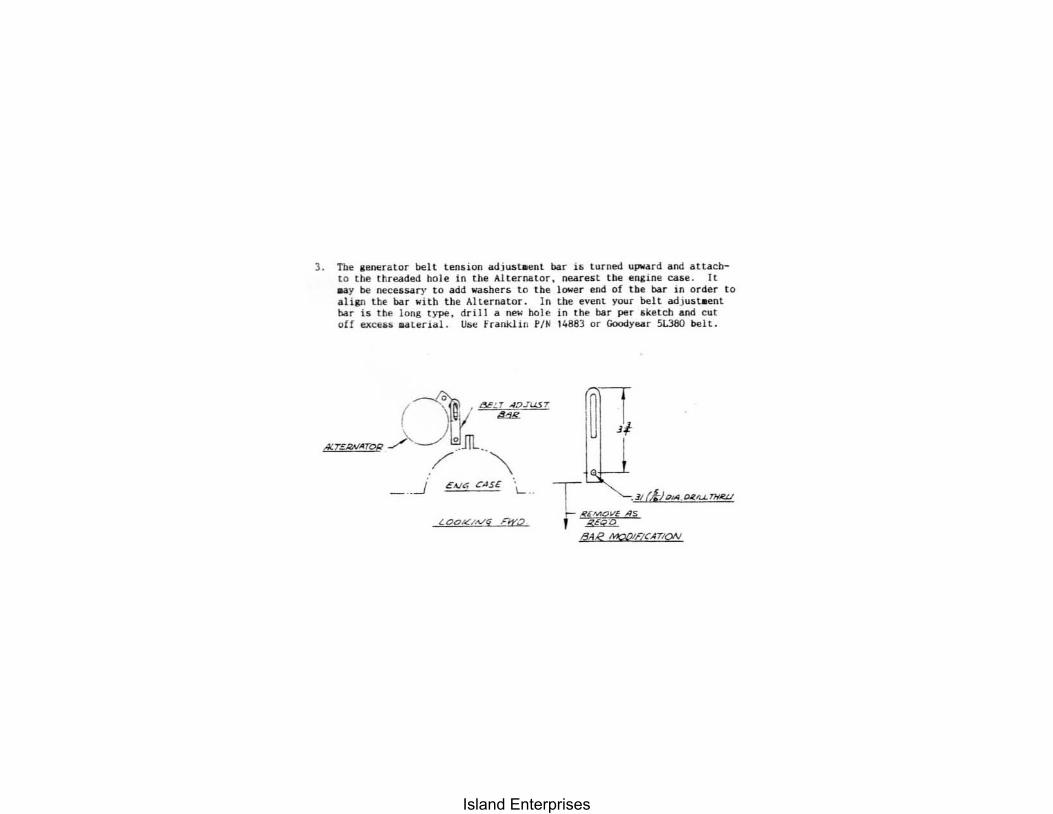
3. The Kenerator be ll t endon adjust.ent bar iti t urned upward and ilttacbto the threaded hole i n the Al t ernator, oea.relOt the en&ine cllIe . I t N Y be necessary to add washerlli to the lower end of tbe bar in order t o ali&n tbe ba r wi th the AlUrnator. In the event your belt adjulit . ent bar is the long type. dri ll a ne~ hole in the bar per sketch .00 cut olf eJlceu uteri"i. Utie frankl i n PIH 14883 or GoodYN r 5i.380 belt .
( 1 / ""'JIJUS7
Alr~f$Arop ~~tlJIL /' . ~
_ .. ..J €~C. C.JS£ 1- ..
LOOYiVy &.2
fl I
.~(4!glA . D£r....LTHIW
Island Enterprises