Embed Size (px)
Citation preview
INSTALLATION INSTRUCTION
Part FTS720601 / Part FTS720601JS
6.0” Long Arm Suspension System
84-2001 Jeep Cherokee XJ Read instructions from start to finish before installation of components
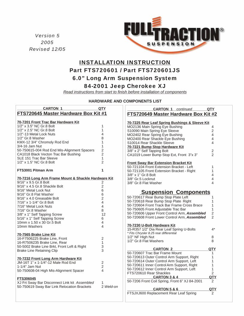
HARDWARE AND COMPONENTS LIST
Version 5
2005
Revised 12/05
CARTON 1 continued QTY
FTS720649 Master Hardware Box Kit #2
70-7225 Rear Leaf Spring Bushings & Sleeve Kit MO2136 Main Spring Eye Bushing 4S10090 Main Spring Eye Sleeve 2MO2402 Rear Spring Eye Bushing 4MO2400 Rear Shackle Eye Bushing 4S10014 Rear Shackle Sleeve 470-7221 Bump Stop Hardware Kit 3/8” x 2” Self Tapping Bolt 2CA1019 Lower Bump Stop Ext, Front 3”x 3” 2
Front Sway Bar Extension Bracket Kit 50-721104 Front Extension Bracket - Left 150-721105 Front Extension Bracket - Right 13/8” x 1” Gr.8 Bolt 43/8” Gr.5 Locknut 43/8” Gr.8 Flat Washer 4
Suspension Components 50-720617 Rear Bump Stop Plate Left 150-720618 Rear Bump Stop Plate Right 150-720604 Front Track Bar Frame Cross Brace 150-750605 Front Adjustable Trac Bar 150-720606 Upper Front Control Arm, Assembled 250-720608 Front Lower Control Arm, Assembled 2
70-7230 U-Bolt Hardware Kit15-R357 1/2” Dia Rear Leaf Spring U-Bolts 4** Fits Chrysler 8.25 rear differential
1/2” NF High Nut 81/2” Gr.8 Flat Washers 8
CARTON 2 QTY50-720607 Trac Bar Frame Mount 150-720613 Outer Control Arm Support, Right 150-720614 Outer Control Arm Support, Left 150-720611 Inner Control Arm Support, Right 150-720612 Inner Control Arm Support, Left 1FTS720610 Rear Shackles 2 CARTON 3 & 4 QTY50-7206 Front Coil Spring, Front 6” XJ 84-2001 2
CARTON 5 & 6 QTYFTSJXJ600 Replacement Rear Leaf Spring 2
CARTON 1 QTY
FTS720645 Master Hardware Box Kit #1
70-7201 Front Trac Bar Hardware Kit 1/2” x 3.5” NC Gr.8 Bolt 11/2” x 2.5” NC Gr.8 Bolt 11/2”-13 Metal Lock Nuts 41/2” Gr.8 Washer 8KMX-12 3/4” Chromoly Rod End 13/4-16 Jam Nut 150-750615-004 Rod End Mis-Alignment Spacers 2CA1018 Black Vecton Trac Bar Bushing 2SLE 151 Trac Bar Sleeve 11/2” x 1.5” NC Gr.8 Bolt 2
FTS3001 Pitman Arm 1
70-7216 Long Arm Frame Mount & Shackle Hardware Kit9/16” x 9.5 Gr.8 Bolt 29/16” x 4.5 Gr.8 Shackle Bolt 2 9/16” Metal Lock Nut 69/16” Gr.8 Flat Washer 69/16” x 4.0 Greasable Bolt 27/16” x 1-1/4” Gr.8 Bolt 47/16” Metal Lock Nuts 47/16” Gr.8 Washer 83/8” x 1” Self Tapping Screw 125/16” x 1” Self Tapping Screw 610mm x 1.50 x 30 Gr.5 Bolt 410mm Washers 4
70-7565 Brake Line Kit 16-F7506225 Brake Line, Front 216-R7506235 Brake Line, Rear 1 50-5002 Brake Line Brkt, Front Left & Right 3Brake Line Retaining Clip 3
70-7232 Front Long Arm Hardware Kit JM-16T 1” x 1-1/4”-12 Male Rod End 21-1/4” Jam Nut 250-750608-04 High Mis-Alignment Spacer 4
FTS306045 XJ Frt Sway Bar Disconnect Link kit Assembled 150-750619 Sway Bar Link Relocation Brackets 2 Weld-on
IMPORTANT NOTES
WARNING: This suspension system will enhance the off-road performance of your vehicle. It will handle differently, both on and off-road, from a factory equipped passenger car or truck. Extreme care must be used to prevent loss of control or vehicle rollover during abrupt maneuvers. Failure to drive this vehicle safely may result in serious injury or death to the driver and passengers. ALWAYS WEAR your seat belts. Reduce your speed, and AVOID sharp turns and other abrupt maneuvers.
Before installing this system, have the vehicle’s alignment checked by a certified technician. The alignment must be within factory specifications and the frame of the vehicle must be sound (no cracks, damage or corrosion).
Do not chrome, cad or zinc plate any of the components in this system. Changing the coated surface of components will void the warranty of your Full Traction Suspension.
Must read.This suspension system was developed using the following tire & wheel combination: 35 X 12.50 tire, 15 x 8 wheel with 4.5 inches of wheel backspacing. Aftermarket Cutout fender flares were used to accommodate the tires. Before installing any other combination, consult your local tire and wheel specialist.
Mandatory Requirements
84-2000 Jeep XJ Cherokee
*Slip Yoke Eliminator
*Rear CV Drive Shaft Replacement
The required installation time for this system is approximately 6 hours. Check off each step as you go.
Thank you for purchasing the best suspension system available. For the best installed system, follow these instructions. If you do not have the tools or are unsure of your abilities, have this system installed by a certified technician.
FULL TRACTION SUSPENSION IS NOT RESPONSIBLE FOR DAMAGE OR FAILURE RESULTING FROM AN IMPROPER OR
MODIFIED INSTALLATION.
ADDITIONAL INFORMATION
Congratulations on your purchase of the highest quality suspension system available for the Jeep XJ. Some of the service procedures require the use of special tools designed for specific procedures. The following tools and supplies are recommended for proper installation of this system.
- Jeep Factory Service Manual - Pitman Arm Puller Tool - Coil Spring Compressor - Universal Steering Linkage Puller - Ball Joint Separator - Prevailing Torque Nuts (for steering linkage) - Drill Motor - Assorted Drills: 1/8” & larger - Tie Down Strap - Torque Wrench - 1/2” drive Ratchet and Sockets - Assorted Combination Wrenches- Heavy Duty Jack Stands - Wheel Chocks or Blocks - Hydraulic Floor Jacks - Center Punch - File- Large “C” Clamps, Bench Vise and Adjustable Straps.- Hammer - Can of Black Semi-Gloss Spray Paint- Wire Brush ( to clean mounting surfaces)- Silicone Spray Lubricant - Tape measure - Safety Glasses ( wear safety glasses at all times)
Page 2
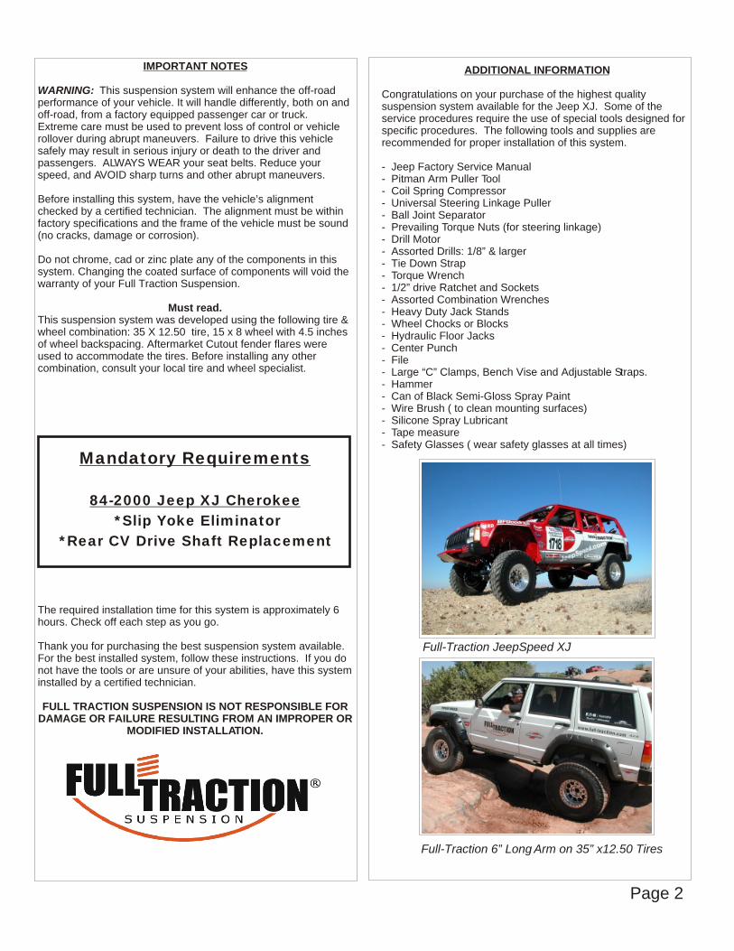
Full-Traction JeepSpeed XJ
Full-Traction 6” Long Arm on 35” x12.50 Tires
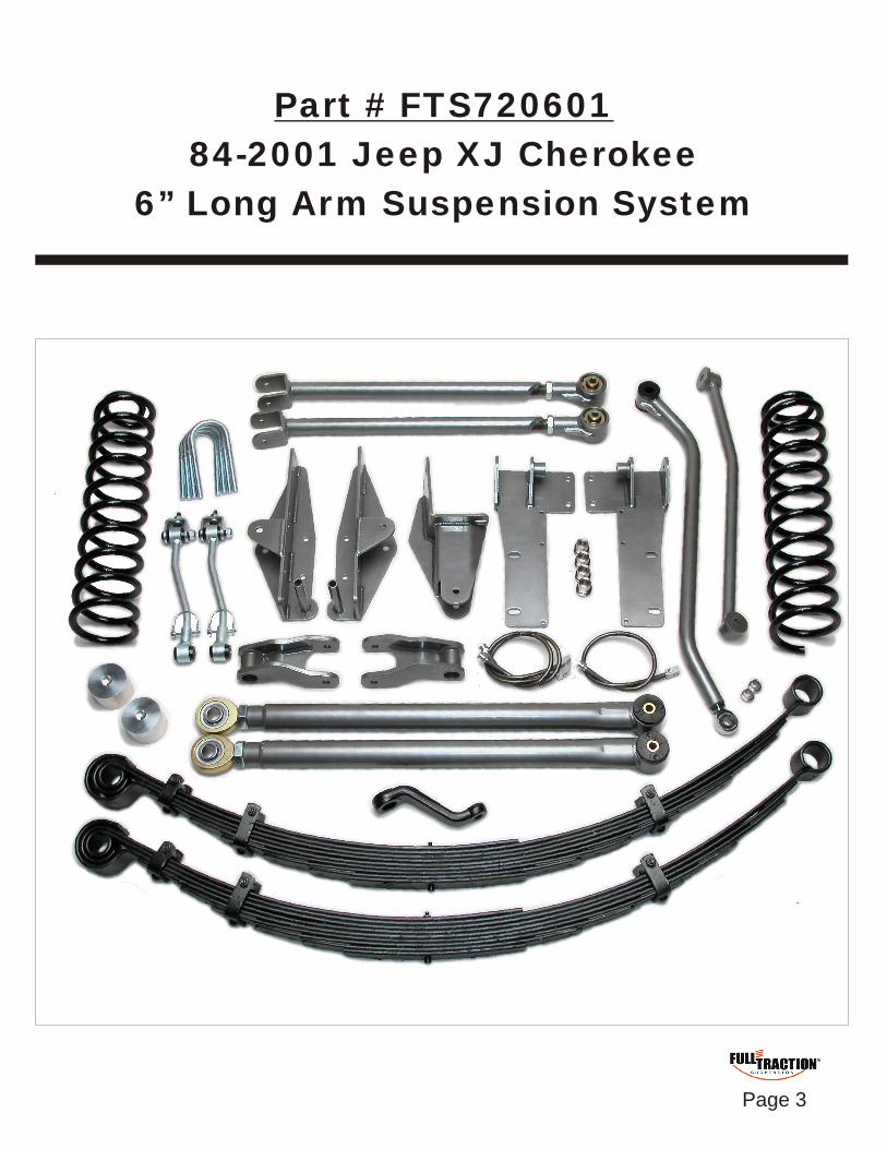
Part # FTS720601
84-2001 Jeep XJ Cherokee
6” Long Arm Suspension System
Page 3
IMPORTANT
READ BEFORE YOU BEGIN INSTALLATION
A Transfer case rear slip yoke eliminator conversion & CV type drive shaft is required to complete the installation. On 84-2000 models, no change in the front drive shaft is required. All parts in this system must be installed. No parts can be eliminated from the installation. Check the parts and hardware against the parts list to assure that your kit is complete. Refer to page #2 of these instructions for a list of tools and supplies needed to perform the installation. Use these instructions as a guide, however experienced installers may want to change the order of installation procedures to suit their needs.
GETTING STARTED
Prepare to remove transfer case.
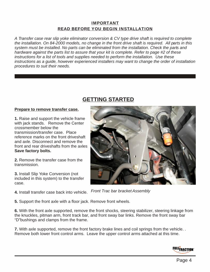
1. Raise and support the vehicle frame with jack stands.
2. Remove the transfer case from the transmission.
3. Install Slip Yoke Conversion (not included in this system) to the transfer case.
4. Install transfer case back into vehicle.
5. Support the front axle with a floor jack. Remove front wheels.
6. With the front axle supported, remove the front shocks, steering stabilizer, steering linkage from the knuckles, pitman arm, front track bar, and front sway bar links. Remove the front sway bar “D”bushings and clamps from the frame.
7. With axle supported, remove the front factory brake lines and coil springs from the vehicle. . Remove both lower front control arms. Leave the upper control arms attached at this time.
Remove the Center crossmember below the transmission/transfer case. Place reference marks on the front driveshaft and axle. Disconnect and remove the front and rear driveshafts from the axles Save factory bolts.
Front Trac bar bracket Assembly
Page 4
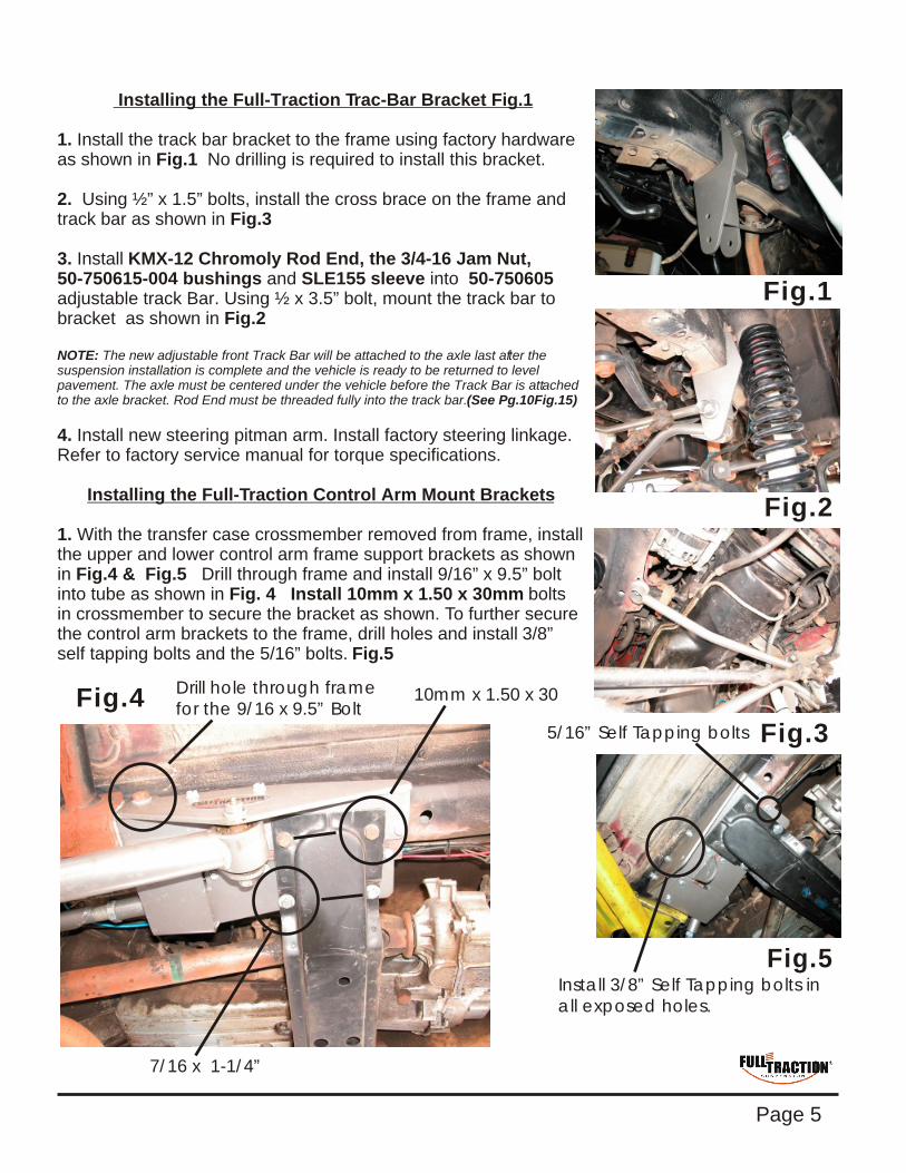
Installing the Full-Traction Trac-Bar Bracket Fig.1
1. Install the track bar bracket to the frame using factory hardware as shown in Fig.1 No drilling is required to install this bracket.
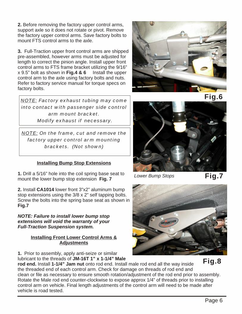
2. nstall the cross brace on the frame and track bar as shown in Fig.3 3. Install KMX-12 Chromoly Rod End, the 3/4-16 Jam Nut, 50-750615-004 bushings and SLE155 sleeve into 50-750605 adjustable track Bar. Using ½ x 3.5” bolt, mount the track bar to bracket as shown in Fig.2
NOTE: The new adjustable front Track Bar will be attached to the axle last after the suspension installation is complete and the vehicle is ready to be returned to level pavement. The axle must be centered under the vehicle before the Track Bar is attached to the axle bracket. (See Pg.10Fig.15)
4. Install new steering pitman arm. Install factory steering linkage. Refer to factory service manual for torque specifications.
Installing the Full-Traction Control Arm Mount Brackets
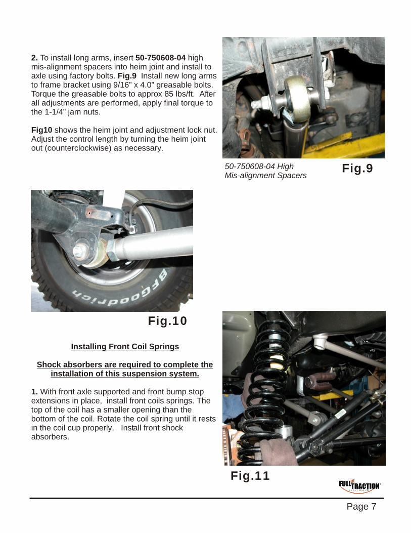
1. With the transfer case crossmember removed from frame, install the upper and lower control arm frame support brackets as shown in Fig.4 & Fig.5 Drill through frame and install 9/16” x 9.5” bolt into tube as shown in Fig. 4 Install 10mm x 1.50 x 30mm bolts in crossmember to secure the bracket as shown. To further secure the control arm brackets to the frame, drill holes and install
Using ½” x 1.5” bolts, i
Rod End must be threaded fully into the track bar.
3/8” self tapping bolts and the 5/16” bolts. Fig.5
Fig.3
Fig.4
Fig.5
Fig.2
Fig.1
Drill hole through framefor the 9/16 x 9.5” Bolt
10mm x 1.50 x 30
7/16 x 1-1/4”
Install 3/8” Self Tapping bolts in all exposed holes.
5/16” Self Tapping bolts
Page 5
2. Before removing the factory upper control arms, support axle so it does not rotate or pivot. Remove the factory upper control arms. Save factory bolts to mount FTS control arms to the axle.
3. Full-Traction upper front control arms are shipped pre-assembled, however arms must be adjusted for length to correct the pinion angle. Install upper front control arms to FTS frame bracket utilizing the 9/16” x 9.5” bolt as shown in Fig.4 & 6 Install the upper control arm to the axle using factory bolts and nuts. Refer to factory service manual for torque specs on factory bolts.
NOTE: Factory exhaust tubing may come
into contact with passenger side control
arm mount bracket.
Modify exhaust if necessary.
Installing Bump Stop Extensions
1. Drill a 5/16” hole into the coil spring base seat to mount the lower bump stop extension Fig. 7
2. Install CA1014 lower front 3”x2” aluminum bump stop extensions using the 3/8 x 2” self tapping bolts. Screw the bolts into the spring base seat as shown in Fig.7
NOTE: Failure to install lower bump stop extensions will void the warranty of your Full-Traction Suspension system.
Installing Front Lower Control Arms & Adjustments
1. Prior to assembly, apply anti-seize or similar lubricant to the threads of JM-16T 1” x 1-1/4” Male rod end. Install 1-1/4” Jam nut onto rod end. Install male rod end all the way inside the threaded end of each control arm. Check for damage on threads of rod end and clean or file as necessary to ensure smooth rotation/adjustment of the rod end prior to assembly. Rotate the Male rod end counter-clockwise to expose approx 1/4” of threads prior to installing control arm on vehicle. Final length adjustments of the control arm will need to be made after vehicle is road tested.
NOTE: On the frame, cut and remove the
factory upper control arm mounting
brackets. (Not shown)
Fig.6
Fig.7Lower Bump Stops
Page 6
Fig.8
2. To install long arms, insert 50-750608-04 high mis-alignment spacers into heim joint and install to axle using factory bolts. Fig.9 Install new long arms to frame bracket using 9/16” x 4.0” greasable bolts. Torque the greasable bolts to approx 85 lbs/ft. After all adjustments are performed, apply final torque to the 1-1/4” jam nuts.
Fig10 shows the heim joint and adjustment lock nut. Adjust the control length by turning the heim joint out (counterclockwise) as necessary.
Installing Front Coil Springs
Shock absorbers are required to complete the installation of this suspension system.
1. With front axle supported and front bump stop extensions in place, install front coils springs. The top of the coil has a smaller opening than the bottom of the coil. Rotate the coil spring until it rests in the coil cup properly. Install front shock absorbers.
Fig.10
Fig.950-750608-04 High Mis-alignment Spacers
Page 7
Fig.11
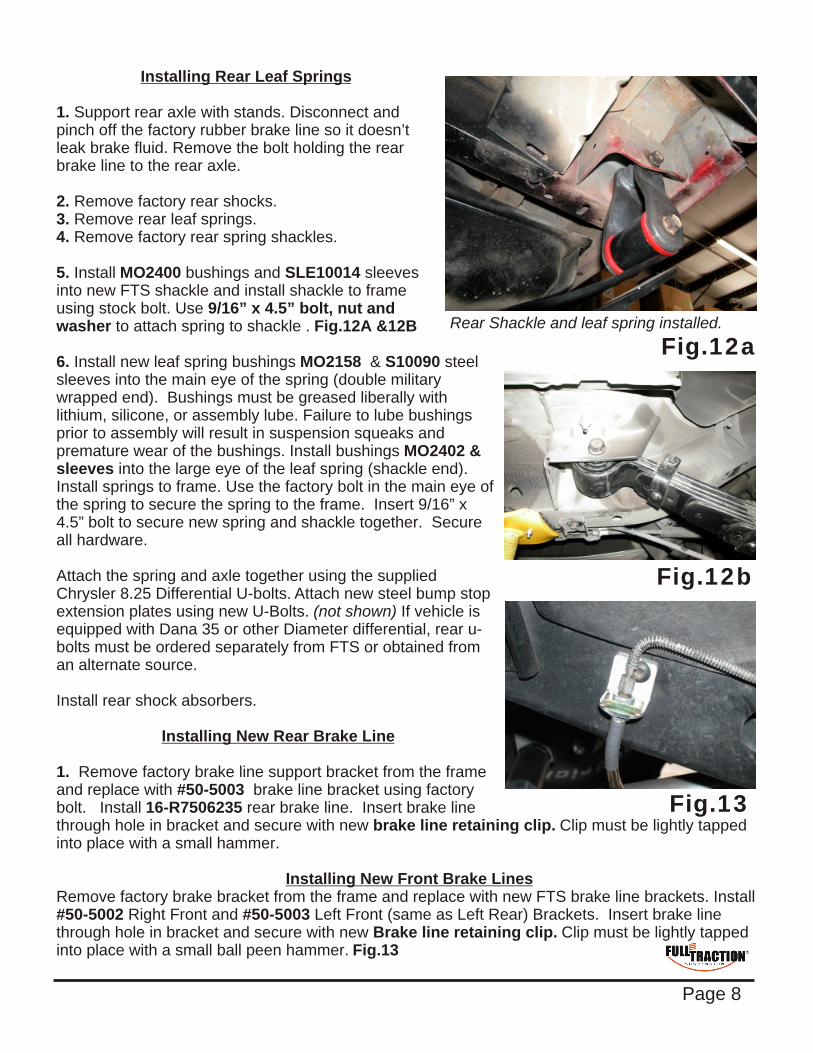
Installing Rear Leaf Springs
1. Support rear axle with stands. Disconnect and pinch off the factory rubber brake line so it doesn’t leak brake fluid. Remove the bolt holding the rear brake line to the rear axle.
2. Remove factory rear shocks. 3. Remove rear leaf springs. 4. Remove factory rear spring shackles.
5. Install MO2400 bushings and SLE10014 sleeves into new FTS shackle and install shackle to frame using stock bolt. Use 9/16” x 4.5” bolt, nut and washer to attach spring to shackle . Fig.12A &12B 6. Install new leaf spring bushings MO2158 & S10090 steel sleeves into the main eye of the spring (double military wrapped end). Bushings must be greased liberally with lithium, silicone, or assembly lube. Failure to lube bushings prior to assembly will result in suspension squeaks and premature wear of the bushings. Install bushings MO2402 & sleeves into the large eye of the leaf spring (shackle end). Install springs to frame. Use the factory bolt in the main eye of the spring to secure the spring to the frame. Insert 9/16” x 4.5” bolt to secure new spring and shackle together. Secure all hardware.
Attach the spring and axle together using the supplied Chrysler 8.25 Differential U-bolts. Attach new steel bump stop extension plates using new U-Bolts. (not shown) If vehicle is equipped with Dana 35 or other Diameter differential, rear u-bolts must be ordered separately from FTS or obtained from an alternate source.
Install rear shock absorbers.
Installing New Rear Brake Line
1. Remove factory brake line support bracket from the frame and replace with #50-5003 brake line bracket using factory bolt. Install 16-R7506235 rear brake line. Insert brake line through hole in bracket and secure with new brake line retaining clip. Clip must be lightly tapped into place with a small hammer.
Installing New Front Brake Lines Remove factory brake bracket from the frame and replace with new FTS brake line brackets. Install #50-5002 Right Front and #50-5003 Left Front (same as Left Rear) Brackets. Insert brake line through hole in bracket and secure with new Brake line retaining clip. Clip must be lightly tapped into place with a small ball peen hammer. Fig.13
Rear Shackle and leaf spring installed.
Fig.12a
Fig.12b
Fig.13
Page 8
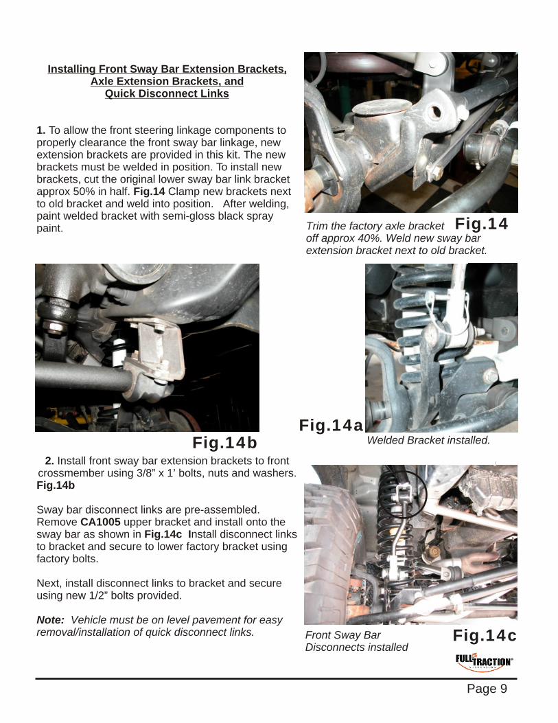
Installing Front Sway Bar Extension Brackets, Axle Extension Brackets, and
Quick Disconnect Links
1. To allow the front steering linkage components to properly clearance the front sway bar linkage, new extension brackets are provided in this kit. The new brackets must be welded in position. To install new brackets, cut the original lower sway bar link bracket approx 50% in half. Fig.14 Clamp new brackets next to old bracket and weld into position. After welding, paint welded bracket with semi-gloss black spray paint.
2. Install front sway bar extension brackets to front crossmember using 3/8” x 1’ bolts, nuts and washers.Fig.14b
Sway bar disconnect links are pre-assembled. Remove CA1005 upper bracket and install onto the sway bar as shown in Fig.14c Install disconnect links to bracket and secure to lower factory bracket using factory bolts.
Next, install disconnect links to bracket and secure using new 1/2” bolts provided.
Note: Vehicle must be on level pavement for easy removal/installation of quick disconnect links. Front Sway Bar
Disconnects installed
Welded Bracket installed.
Fig.14
Fig.14aFig.14b
Page 9
Trim the factory axle bracket off approx 40%. Weld new sway bar extension bracket next to old bracket.
Fig.14c
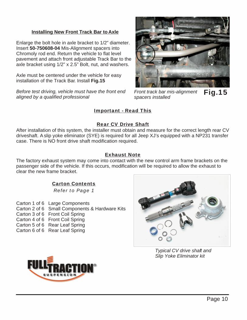
Installing New Front Track Bar to Axle
Enlarge the bolt hole in axle bracket to 1/2” diameter. Insert 50-750608-04 Mis-Alignment spacers into Chromoly rod end. Return the vehicle to flat level pavement and attach front adjustable Track Bar to the axle bracket using 1/2” x 2.5” Bolt, nut, and washers.
Axle must be centered under the vehicle for easy installation of the Track Bar. Install Fig.15
Before test driving, vehicle must have the front end aligned by a qualified professional
Important - Read This
Rear CV Drive Shaft After installation of this system, the installer must obtain and measure for the correct length rear CV driveshaft. A slip yoke eliminator (SYE) is required for all Jeep XJ’s equipped with a NP231 transfer case. There is NO front drive shaft modification required.
Exhaust Note The factory exhaust system may come into contact with the new control arm frame brackets on the passenger side of the vehicle. If this occurs, modification will be required to allow the exhaust to clear the new frame bracket.
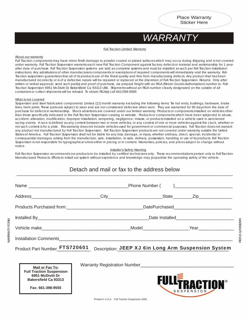
Carton Contents
Refer to Page 1
Carton 1 of 6 Large Components Carton 2 of 6 Small Components & Hardware KitsCarton 3 of 6 Front Coil SpringCarton 4 of 6 Front Coil SpringCarton 5 of 6 Rear Leaf SpringCarton 6 of 6 Rear Leaf Spring
Typical CV drive shaft and Slip Yoke Eliminator kit
Page 10
Front track bar mis-alignment spacers installed
Fig.15
Full Traction Limited Warranty
About our warranty Full Traction components may have minor finish damage to powder coated or plated surfaces which may occur during shipping and is not covered under warranty. Full Traction Suspension warrants each new Full Traction Component against factory defects in material and workmanship for 1 year after date of purchase. Full Traction Suspension systems are sold as complete systems and must be installed as such per Full-Traction installation instructions. Any substitutions of other manufacturers components or exemptions of required components will immediately void the warranty. Full-Traction suspension guarantees that all of its products are of the finest quality and free from manufacturing defects. Any product that has been manufactured incorrectly or is of a defective nature will be repaired or replaced at the discretion of Full-Traction Suspension. Returns: Only after written or verbal approval, send such part(s) and proof of purchase, via prepaid freight with an RGA (Return Goods Authorization) number to: Full-Traction Suspension 6951 McDivitt Dr. Bakersfield Ca 93313 USA. Shipments without an RGA number clearly designated on the outside of all containers or collect shipments will be refused. To obtain RGA(s) call 661/398-9585
What is not coveredSuspension and steel fabricated components: Limited (12) month warranty excluding the following items: Tie rod ends, bushings, hardware, brake lines, heim joints. These parts are subject to wear and are not considered defective when worn. They are warranted for 90 days from the date of purchase for defects in workmanship. Shock absorbers are covered under our limited warranty. Products or components installed on vehicles other than those specifically indicated in the Full-Traction Suspension catalog or website. Products or components which have been subjected to abuse, accident, alteration, modification, improper installation, tampering, negligence, misuse, or products installed on a vehicle used in sanctioned racing events. A race is defined as any contest between two or more vehicles, or any contest of one or more vehicles against the clock, whether or not such contest is for a prize. This warranty does not include vehicles used for government or commercial purposes. Full Traction does not warrant any product not manufactured by Full Traction Suspension. Full Traction Suspension products are not covered under warranty outside the United States of America. Full Traction Suspension shall not be liable for any loss, damage, or injury, whether ordinary, direct, special, incidental or consequential damages, arising from the manufacture, sale, installation, re-sale, delivery, possession, handling or use of its products. Full Traction Suspension is not responsible for typographical errors either in pricing or in content. Warranties, policies, and prices subject to change without notice.
Installer’s Safety WarningFull-Traction Suspension recommends our products to be installed by certified technicians only. These recommendations pertain only to Full-Traction Manufactured Products. Efforts to install our system without experience and knowledge may jeopardize the operating safety of the vehicle.
---------------------------------------------------------------------------------------------------------------------------------------------------
Name _____________________________________________Phone Number ( )__________________________
Address_______________________________City______________________State________Zip_______________
Products Purchased from:_______________________________DatePurchased__________________________
Installed By__________________________________________________Date Installed__________________________
Vehicle make________________________________________Model_____________________Year________________
Installation Comments______________________________________________________________________________
Product Part Number_______________ Description:__________________________________________________
Warranty Registration Number__________________________________________
WARRANTY
Detach and mail or fax to the address below
Mail or Fax To: Full Traction Suspension
6951 McDivitt Dr Bakersfield Ca 93313
Fax: 661-398-9555
Place Warranty Sticker Here
Printed in U.S.A. Full-Traction Suspension 2005
WA
RRA
NTY
FO
RM
WA
RRA
NTY FO
RM
FTS720601 JEEP XJ 6in Long Arm Suspension System