Embed Size (px)
Citation preview

581-484F 8’ MODERN BIPOD ADA SWING
Installation Guide
1
INSTALLATION INSTRUCTIONS
581-484F
8’ MODERN BIPOD ADA SWING Please read the entire manual before beginning installation.
1 CTN 8 PIPE 3 WF 12 TOTAL PCS 200# WEIGHT CLASS 70
581-484F 8’ MODERN BIPOD ADA SWING
Installation Guide
2
TAB SECTION INDEX
1. 3D AND 2D DRAWINGS
2. INSTALLATION GUIDE
3. INSTALLATION STEPS
4. COMPONENT INSTALLATION
5. APPENDIX
6. ORIGINAL COMPONENT MAINTENANCE FORMS
7. COMPLETED COMPONENT MAINTENANCE FORMS

581-484F 8’ MODERN BIPOD ADA SWING
Installation Guide
3
Table of Contents
3D DRAWING ..........................................................................................
TOP DOWN VIEW ...................................................................................
FOOTING VIEW .......................................................................................
Important ............................................................................................... 6 When your receive your playground ................................................. 6 Before you begin ........................................................................................ 6
Safety Surfacing ................................................................................... 8
Tools and Materials ............................................................................ 9
BEFORE BEGINNING ........................................................................ 10 SITE REQUIREMENTS ............................................................................ 10 MAINTENANCE: ....................................................................................... 10 PLAY AREA: ............................................................................................... 10
Installation Punch List ........................................................................ Footing Layout Example............................................................................ Step 1: Layout........................................................................................... 11 Step 2: Holes ............................................................................................. 11 Step 3: Deck, Post & Component Installation ............................... 12 Step 4: Concrete ...................................................................................... 12 Step 5: Last Step ...................................................................................... 12 Four Hole Bracket & Panel Bracket Installation .............................. Other Installation Tips ......................................................................... 13
SUPERVISION GUIDE ....................................................................... 14
HARDWARE DRAWINGS
COMPONENT INSTALLATION INSTRUCTION SETS
APPENDIX
FINAL INSTALLATION STEPS
MAINTENANCE AND INSPECTION

581-484F 8’ MODERN BIPOD ADA SWING
Installation Guide
4

581-484F 8’ MODERN BIPOD ADA SWING
Installation Guide
5

581-484F 8’ MODERN BIPOD ADA SWING
Installation Guide
6
Important
Please read completely before beginning installation.
This equipment has been designed for safety as well as challenge and fun. This
equipment has been designed to reduce injuries and therefore must be installed
“Step by Step” per our Instructions.
The U.S. Consumer Product Safety Commission (CPSC) published a report
stating 79% of all playground injuries treated in U.S. Emergency Rooms was the
result of a fall. It is critical that you refer to the Protective Surfacing section of
these instructions, located on the next page prior to installing your playground.
As the owner you are responsible for the safe installation of not only the play
equipment, but also the safety of the site.
When your receive your playground
Identify all parts by comparing them to the part list and component
instruction pages.
Always compare the number of pallets, cartons or other items the BOL
has listed with the number actually received. Note the any discrepancies
on the BOL.
Also note any obvious damage to the packing materials, pallets or
components on the BOL.
Equipment should be inventoried and installed within a few days of
receipt. The packing materials are meant to protect the equipment
during shipping and not for storage. Heat, weather and sunlight can
damage the packing materials, which can impact the components. If
storage is required you must store the equipment in a controlled
environment away from heat, moisture and sunlight. SportsPlay
recommends carefully unpacking the unit and taking an inventory before
storing the equipment. Care should be taken with all powder coated and
thermoplastic-coated parts to prevent damage to the coating.
You have 30 days from receipt of your equipment to file a claim for
missing or damaged parts.
Before you begin
Review your playground footing and top view drawings to ensure your site is
large enough. These guidelines are available from the CPSC (contact
information for the CPSC is located on the next page).
Read through the entire instruction booklet before beginning the actual
installation.
Before you begin preparing the site or digging any holes you must first
contact you local utility companies so they can visit the site and mark all
of the buried utilities. In the U.S. you may call 811 and your call will be
routed to your local utility center.
This equipment was designed to install on a clear and level site. There
should be no more than 3” of grade variations in a 10’ span.
Footing layout is the first critical step once the installation begins. Mark
all holes using the footing diagram. Prior to digging holes compare the
measurements from the footing diagram to the actual site markings to
ensure accuracy. Then check it again! (Footing info is located on pg 16
in this guide)
Our posts are manufactured to accommodate 12” of protective surfacing.
Evaluate the site for drainage. To ensure good drainage around the
equipment consult a local professional.
Do not leave the jobsite un-attended during installation unless all access
points to the play area are secure, all bolts and fasteners are tight and all
ground holes are covered.

581-484F 8’ MODERN BIPOD ADA SWING
Installation Guide
7
SportsPlay Equipment inc. has provided two warning labels that state:
“WARNING – Installation over a hard surface such as concrete, asphalt
or packed earth may result in serious injury or death from falls.” These
labels must be installed on vertical posts as per ASTM F1487.
Instructions for the placement of these labels are included in the
appendix of this booklet.
SportsPlay will provide manufacturer identification labels that must be
installed on the structure during installation per ASTM F1487.
Installation instructions for these labels are included in the appendix of
this instruction manual.
Labels must be replaced when they are no longer legible. Contact your
distributor for replacement labels.

581-484F 8’ MODERN BIPOD ADA SWING
Installation Guide
8
Safety Surfacing
WARNING! – INSTALLATION OVER A HARD SURFACE SUCH AS
CONCRETE, ASPHALT OR PACKED EARTH MAY RESULT IN
SERIOUS INJURY OR DEATH FROM A FALL
Because accidental falls are likely to occur around play equipment, SportsPlay
Equipment Inc. recommends that a resilient safety surfacing that will meet
standard ASTM F1292 be placed under and around the structure and extend
throughout the entire use zone.
SportsPlay Equipment Inc. does not manufacture safety surfacing. All
manufacturers of safety surfacing require different depths of surfacing for fall
heights. Consult your surfacing supplier about the required safety surfacing
depth for your play equipment.
SportsPlay Equipment Inc. manufactures all playgrounds to accommodate
12” of safety surfacing. If you intend to adjust the height of the surfacing
you will need to adjust the depth of the footing to accommodate the
surfacing height.
Refer to the CPSC Handbook for Public Playground Safety for the recommended
type and depth of the protective surfacing as well as all other playground safety
concerns.
For a copy of the most current issue of the CPSC Handbook for Public
Playground Safety, write to:
U.S. Consumer Product Safety Commission
Office of Information and Public Affairs
Washington DC, 20207
USA
Call - 1-800-638-2772 (US and Canada only)
Call - 301-504-0990
Direct Link - http://www.cpsc.gov
For a copy of either the standard for surfacing (ASTM F1292) or for play
equipment (ASTM 1487) write to:
American Society for Testing and Materials
100 Bar harbor drive
West Conshohocken PA, 19428-2959
USA
Call – 618-832-9585
Web Site – www.astm.org
You must consider the type of safety surfacing you will use before beginning
the installation process. There are two general types, organic/loose fill or
synthetic unitary (pour in place). You must know which type of surfacing
you are going to use prior to installing the playground. This unit was
designed for 12” of loose fill surfacing so if the customer wants to use a
synthetic unitary product that has a much smaller height than 12” you must
dig the footing holes deeper to allow for the difference.
If loose fill surface material is to be used (example: wood mulch) you will
need to consider containment borders. There are many products to choose
from including hard plastic and natural products such as wood (Creosoted
railroad ties are NOT recommended for use as borders in a play area). Loose
fill materials are easily displaced so use of some type of containment border
is necessary to keep the surfacing material inside the intended area. Some
customers also prefer to have a weed mat installed to prevent weed growth.
Choose a mat that will prevent growth but will also allow for drainage.

581-484F 8’ MODERN BIPOD ADA SWING
Installation Guide
9
Tools and Materials
List is for tools and materials needed that are not included with the
playground
Follow manufacturer’s guidelines for proper use of tools and materials.
The best method (also the easiest) to dig the postholes is using a
tractor with a 12” auger attachment.
Shovels (long handled spades)
Post hole digger
Wheelbarrow
Large construction bar (5’)
Claw hammer
Large dead-blow rubber hammer
Small sledgehammer to use in blocking the posts
Strong and sturdy step ladders
Extension cords & power supply
Levels – Magnetic torpedo and 4’ long levels
Scrap lumber to use for shims in post holes to keep posts level
Blocking materials for the post holes (bricks, concrete blocks, etc.)
Files and sand paper
Safety surfacing
Spray paint to mark holes
String line
Cement (2,500 psi minimum)
Straight line or transit level (and tripod) for ensuring hole depths are
at the same level

581-484F 8’ MODERN BIPOD ADA SWING
Installation Guide
10
BEFORE STARTING INSTALLATION OF YOUR PLAYGROUND,
PLEASE READ INSTRUCTIONS THOROUGHLY.
BEFORE BEGINNING
SITE REQUIREMENTS
The Playground system is designed to suit a level site. Should there be any falls
or slopes on the site; care should be taken to accommodate the entry and exit points
and to maintain the correct height. There should not be more than 3” of drop in grade
per every 10’.
The site must be inspected for natural obstacles such as roots or rocks that may
be a trip hazard, poor drainage and sharp objects such as glass.
Every state has different rules and regulations governing digging, some are
stricter than others. In addition, 62 separate One Call Centers serve different
areas of the country; now 811 will connect you directly to your local One Call
Center. Prior to digging, be sure to call 811 or the local One Call Center to
prevent accidentally disrupting local utility service.
MAINTENANCE:
As an owner, it is most important that you are aware of your responsibility to
insure safe use of your new equipment. It is necessary to install equipment
according to the installation instructions provided and inspect the equipment at
regular intervals. During inspection, if any part is found damaged or excessively worn,
equipment should be closed immediately. A maintenance section is included in the
appendix of this instruction booklet.
If a part is missing or damaged the playground must be put out of service while
the part is replaced. Lack of maintenance will result in premature wear, reduced
life expectancy, and possible failure that may result in injury.
All SportsPlay Equipment play events have been engineered to meet all
applicable safety guidelines, but if installed improperly, these problems may
occur:
Entrapment gaps (between 3 1/2” and 9”)
String Entanglements
Protrusions
Make sure that any bolt end that protrudes more than 2 threads past the face of the
nut is trimmed and de-burred smoothly. Always double-check your work.
Installation must adhere to the manufacturer’s assembly manual and all other applicable
safety guidelines.
PLAY AREA:
The area immediately above and around the play structure must be free of any
obstructions such as:
Trees
Other Play Equipment
Buildings
Overhead Power lines
Make sure the play area has all the required safety surfacing and the
minimum fall zones as required by the safety guidelines. These guidelines can
be found at www.cpsc.gov.
CHILDREN MUST BE SUPERVISED AT ALL TIMES. No playground is
safe without adult supervision!
There may be situations that require you to modify the layout or use your own
judgment. If you have any questions contact you distributor.
Reading this entire manual before beginning the installation will help you to
ensure your equipment is installed and maintained correctly.
581-484F 8’ MODERN BIPOD ADA SWING
Installation Guide
11
Step 1: Layout
1. Lay structure in the desired location using the top view layout drawing.
Measure from each post to ensure there is adequate space for any
component and the components fall zone. This drawing is a standard
drawing and does not represent the actual playground you are installing.
2. Most installers like to orientate the playground so that the entry point of
the playground is facing either the sidewalk or the direction from which
the children are entering the play area.
Step 2: Holes
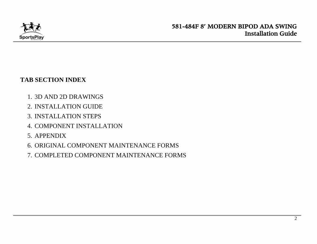
1. If the site grade is not level you have to adjust the footing depth to
maintain a level footing. Check with building codes to ensure you meet
required hole depth and width. If a deeper footing is required you must
add blocking materials to the hole to keep the post depth in accordance
with the footing side view drawing on the next page.
2. Once the structure is in the desired location within the play area, mark
the locations of the post by inserting a stake into the center of each post
location (see drawing below for an example). If using spray paint to
mark location please be careful not to spray the post.
3. Match the post location marks with the footing layout in the front of this
booklet. Dig your holes using the main post footing drawing below. If
your surface grade is not level you should start with the lowest point and
use that hole depth to level all other holes too. The footing drawing
below indicates a depth of 22” plus the thickness of a brick (or the
thickness of whatever blocking material you will use instead of a brick).
This depth is for 12” of surfacing only. If you are using something other
than 12” of surfacing, such as 3” of rubber your hole depth would have
to be 31” plus the thickness of a brick to allow for less surfacing
material.
4. It is recommended that you use a transit to level the remaining post
holes to the first hole in order to ensure that the posts are level.
FOOTING SIDE VIEW

581-484F 8’ MODERN BIPOD ADA SWING
Installation Guide
12
Step 3: Post & Component Installation
1. We recommend installing the posts once the post are square and level
you may add the concrete (concrete with a minimum of 2,500 psi should
be used). Mix concrete per manufacturers instructions and let it cure for
at least 24 hours before continuing.
2. NEVER LEAVE THE INSTALLATION SITE UNATTENDED
WITHOUT ROPING OFF THE AREA AND EQUIPMENT,
INSTALLING ALL HARDWARE, SECURING TOOLS AND
EQUIPMENT, AND COVERING OPEN HOLES WITH A RIGID
MATERIAL (PLYWOOD). CHILDREN WILL TRY TO USE
THE EQUIPMENT EVEN THOUGH ITS NOT FULLY
ASSEMBLED. YOU MUST TAKE ACTION TO PREVENT
INJURY AND DAMAGE.
Step 4: Concrete
1. Verify all swing posts and fittings are tight, level and square. Once the
unit is verified to be level and square you may start installing concrete.
You must use concrete with a minimum of 2,500 psi.
2. Always pre mix the concrete to the manufactures directions before
pouring it into the hole. Never put dry concrete in the hole. Typically
each main posthole requires two 80-pound bags of concrete.
3. Allow concrete to set in accordance with manufacturers directions. Fill
holes too about 2” below the surface with concrete. Once the hole has
been filled with concrete, slope the top of the concrete down and away
from the post to keep water from seeping between the post and the
concrete.
4. Secure playground area to prevent access while the concrete is setting
for a minimum of 48 hours.
5. SportsPlay recommends having a CPSI (certified playground safety
inspector) present during installation. If that’s not possible you should
have the completed playground (after surfacing is in place) inspected by
a CPSI.
Step 5: Last Step
1. After concrete has completely set, backfill all holes with dirt.
2. Install surfacing.

581-484F 8’ MODERN BIPOD ADA SWING
Installation Guide
13
Other Installation Tips
If you are mocking up components with the intention of removing
the hardware at some point, you may want to apply lubricating oil to
the hardware. Stainless steel hardware has a tendency to seize so if you
are planning on removing the hardware you may want to apply lubricant
to prevent this.
Unless specified in the specific component instruction step, do not
tighten the hardware completely until the entire unit is assembled.
581-484F 8’ MODERN BIPOD ADA SWING
Installation Guide
14
SUPERVISION GUIDE
Although the equipment is designed, installed and maintained in accordance with
all safety guidelines adult supervision is required.
Not all equipment is appropriate for all ages. Direct children to age appropriate
equipment.
Younger children will require more supervision than older children.
While eliminating accidents is not likely, following these guidelines will help
minimize accidents.
Basic playground safety for supervisors:
Make sure all safety surfacing is in place and at the correct height.
Inspect area for hard or sharp objects and remove them.
No dangerous horseplay in the play area. (Jumping from dangerous
heights, displacing of surfacing, etc…)
Inspecting for missing or broken equipment. (Do not allow children to
play on broken equipment or equipment with missing components).
Make sure there are no unsafe modifications (especially ropes tied to
equipment). Remove all unsafe modifications and close the equipment
for play until they are removed.
Keep children in the designated play area.
Do not let children play on wet equipment.
Prevent overcrowding on play equipment.
Loose clothing, hoods, strings or jewelry shall be tight or not worn
while playing to prevent strangulation.
Ensure the temperature of the equipment is not hazardous. Direct
sunlight exposure can increase the temperature of the equipment high
enough to cause injury.
Inspect the playground every day using the General Inspection Checklist
located in the appendix of this manual
The easiest method for performing the daily inspection with the
checklist is to laminate the checklist and use a dry erase marker to mark
the items off before opening the play area

581-484F 8’ MODERN BIPOD ADA SWING
Installation Guide
15
½ X ½ SET
SCREW
2 3/8” SWING
HANGER
5/16 X 1 BUTTON
HEAD NUT
5/16 X 2 ½ BUTTON
HEAD BOLT
5/16 LOCK
WASHER
3/16 ALLEN WRENCH (YELLOW BAG)
¼ ALLEN WRENCH (BLUE BAG)
5/16 WRENCH (RED BAG)

581-484F 8’ MODERN BIPOD ADA SWING
Installation Guide
16
COMPONENT INSTALLATION INSTRUCTIONS

February 14, 2018 1
581-484F 8’ MODERN BIPOD ADA SWING
INSTALLATION INSTRUCTION
INSTALLATION DETAILS
Recommended crew (Adult): 2
Installation time: 4 hr
User age: 5-12
Use zone: 32’ x 36’
Weight: 200 lbs
SURFACING: Use of safety surfacing in compliance with
ASTM specification F1292 is required.
MAINTENANCE:
As the owner of the playground you are responsible for
maintenance of the equipment and play area. A
maintenance schedule must be developed and the
equipment inspected frequently. A maintenance section
that includes component specific maintenance
requirements is included at the end of this manual.
Be sure to inspect surfacing for foreign objects that could
cause injury and that sufficient surfacing are in place in
accordance with ASTM and CPSC standards.

February 14, 2018 2
581-484F 8’ MODERN BIPOD ADA SWING
INSTALLATION INSTRUCTION
PARTS LIST
ID PART # DESCRIPTION QTY
1 583-522 Swing End 2
2 583-523 Center Fitting 1
3 343-210A 2 3/8” x 11’ Pipe 7
4 523-603 2 3/8” x 7’6” Pipe 1
5 585-520 2 3/8” Swing Hanger 6
6 196-802 ½” x ½” Socket Set Screw 10
7 116-545 5/16” x 2 ½” Button Head Bolt 4
8 216-512 5/16” x 1” Button Head Nut 4
9 326-501 5/16” Lock Washer 4
10 416-350 3/16” Socket Key 2
11 416-400 ¼” Socket Key 2
12 416-500BPK 5/16” Socket Key 1
13 805-532 Warning Label 1
14 805-534 SportsPlay Label 1
15 516-400 Locktite 1
NOTE: Keep a copy of these instructions on file to assist you
with maintenance and replacement parts.

February 14, 2018 3
581-484F 8’ MODERN BIPOD ADA SWING
INSTALLATION INSTRUCTION
FOOTING INFORMATION
Total footing depth is 24” less the height of the surfacing
plus the height of the blocking material. If you are using
12” of surfacing the footing hole would need to be 12” plus
the height of the blocking material (refer to both the side
and front cutaway views to the right).
If the Play structure is installed on an unlevel grade you
must adjust the footing depth to accommodate the grade.
For instance, if the grade for this component is 1” higher
than the surface grade of the main playground post you
must dig your footing hole 1” deeper.
You must place the bottom of the support post or slide leg
on a suitable flat blocking material to prevent it from
sinking further into the soil. We recommend you use a
brick, block of wood or several inches of gravel. The
footing depth does not include this blocking material since
materials used often vary.
It is the owner/installers responsibility to check local
building codes and to comply with those codes. All footing
depths listed here are recommendations and local soil types
and frost lines may require a deeper and/or wider footing
depth. If that’s the case you must add more blocking
material to accommodate the deeper footing, as the post
length will still only be installed at the depth listed in this
instruction manual.
Assemble the entire unit before adding the concrete unless
instructed to do so in the individual component instruction
sections.

February 14, 2018 4
581-484F 8’ MODERN BIPOD ADA SWING
INSTALLATION INSTRUCTION
ELEVATION AND
FOOTING LAYOUT VIEW

February 14, 2018 5
581-484F 8’ MODERN BIPOD ADA SWING
INSTALLATION INSTRUCTION
SPECIFICATIONS
Tube – FloCoat® Galvanized 2 3/8” O.D. and 2 7/8” O.D.
Hardware – Stainless steel & tamper resistant
SPECIAL SAFETY & ASTM COMPLIANCE NOTES
INSTALLATION TIPS & TROUBLE SHOOTING
Apply locktite to all bolts during assembly prior to
completely tightening them.
Stainless Steel hardware can occasionally be difficult to use
particularly if you need to take them out to make an
adjustment. It is recommended that you add a drop of oil to
bolts that may have to be removed before you install them.
Do not tighten bolts all the way until the unit is completely
assembled and all components are square and level.
Identify and separate all parts by referencing the detail
drawings and the parts list.
As you unpack and separate the components use the
cardboard sheets that were used for packing and shipping to
prevent damage to the components. This is particularly true
all Powder Coated and Thermoplastic coated components,
by setting the components on top of the cardboard.
February 14, 2018 6
581-484F 8’ MODERN BIPOD ADA SWING
INSTALLATION INSTRUCTION
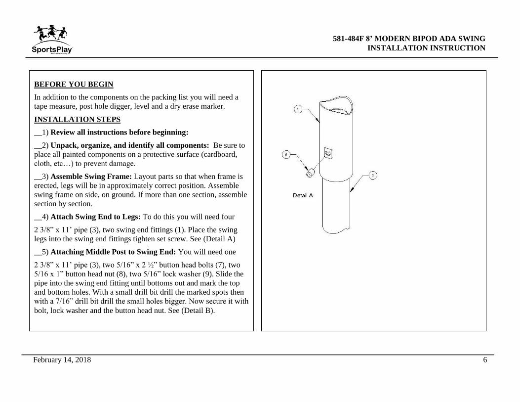
BEFORE YOU BEGIN
In addition to the components on the packing list you will need a
tape measure, post hole digger, level and a dry erase marker.
INSTALLATION STEPS
__1) Review all instructions before beginning:
__2) Unpack, organize, and identify all components: Be sure to
place all painted components on a protective surface (cardboard,
cloth, etc…) to prevent damage.
__3) Assemble Swing Frame: Layout parts so that when frame is
erected, legs will be in approximately correct position. Assemble
swing frame on side, on ground. If more than one section, assemble
section by section.
__4) Attach Swing End to Legs: To do this you will need four
2 3/8” x 11’ pipe (3), two swing end fittings (1). Place the swing
legs into the swing end fittings tighten set screw. See (Detail A)
__5) Attaching Middle Post to Swing End: You will need one
2 3/8” x 11’ pipe (3), two 5/16” x 2 ½” button head bolts (7), two
5/16 x 1” button head nut (8), two 5/16” lock washer (9). Slide the
pipe into the swing end fitting until bottoms out and mark the top
and bottom holes. With a small drill bit drill the marked spots then
with a 7/16” drill bit drill the small holes bigger. Now secure it with
bolt, lock washer and the button head nut. See (Detail B).

February 14, 2018 7
581-484F 8’ MODERN BIPOD ADA SWING
INSTALLATION INSTRUCTION
INSTALLATION STEPS CONTIUDE
__6) Attaching Swing Hangers: You will need eight swing
hangers (5), attach the swing hangers to the top rail following
spacing on page 4. See (Detail C).
__7) Dig footing holes: Footing holes may be marked out and dug
from footing layout; however, it is easier to position swing in
proper location, mark holes, move swing aside, and dig holes.
__8) Stand swing upright onto legs and brace in footing holes so
that 2’ – 3’ of pipe will be under intended level of resilient
surfacing and the top rail is at desired height. Plumb and level
entire unit. Tighten all set screws.
__9) Once the entire playground has been installed and you have
verified that the entire playground is level you can add the
concrete to the footing holes. Be sure to use concrete with a
minimum 2,500 psi and mix the concrete per the manufacturer’s
directions before you pour it into the footing hole. Once the
footing has been filled with concrete you should rope of the area for
a minimum of 48 hours to allow the concrete set properly.

February 14, 2018 8
581-484F 8’ MODERN BIPOD ADA SWING
INSTALLATION INSTRUCTION
INSTALLATION STEPS CONTINUED
__10) Once the concrete has set, back fill dirt over the footing
holes; inspect the area and components for tools, hazardous debris
and sharp edges. Verify all components are installed and all
hardware is tight and then install the safety surfacing.
__11) Inspect the components: for sharp edges and if necessary
file them down and apply touch up paint.


![581 08& (UJHEQLVVH 581 08& NP 581 · 581 08& _ _ (ujheqlvvh 581 08& np 581,qriil]lhooh (ujheqlvvh _ 0lqqhu 3odw] 3o $. 1dph ±5lyhur /xlv &duorv *8$ 9huhlq ±)rwr1hwwr %uxwwr 3dv]wru](https://img.pdfslide.net/doc/110x75/60b33454875bc120ef6fb957/581-08-ujheqlvvh-581-08-np-581-581-08-ujheqlvvh-581-08.jpg)