Embed Size (px)
Citation preview
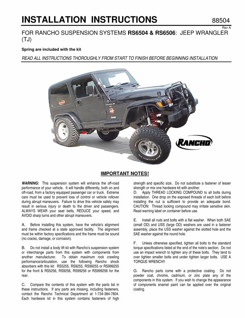
INSTALLATION INSTRUCTIONS 88504 Rev A
FOR RANCHO SUSPENSION SYSTEMS RS6504 & RS6506: JEEP WRANGLER (TJ) Spring are included with the kit
READ ALL INSTRUCTIONS THOROUGHLY FROM START TO FINISH BEFORE BEGINNING INSTALLATION
IMPORTANT NOTES! WARNING: This suspension system will enhance the off-road performance of your vehicle. It will handle differently, both on and off-road, from a factory equipped passenger car or truck. Extreme care must be used to prevent loss of control or vehicle rollover during abrupt maneuvers. Failure to drive this vehicle safely may result in serious injury or death to the driver and passengers. ALWAYS WEAR your seat belts, REDUCE your speed, and AVOID sharp turns and other abrupt maneuvers. A. Before installing this system, have the vehicle's alignment and frame checked at a state approved facility. The alignment must be within factory specifications and the frame must be sound (no cracks, damage, or corrosion). B. Do not install a body lift kit with Rancho’s suspension system or interchange parts from this system with components from another manufacturer. To obtain maximum rock crawling performance/articulation, use the following Rancho shock absorbers with this kit: RS5255, RS9255, RS99255 or RS999255 for the front & RS5256, RS9256, RS99256 or RS999256 for the rear. C. Compare the contents of this system with the parts list in these instructions. If any parts are missing, including fasteners, contact the Rancho Technical Department at 1-734-384-7804. Each hardware kit in this system contains fasteners of high
strength and specific size. Do not substitute a fastener of lesser strength or mix one hardware kit with another. D. Apply THREAD LOCKING COMPOUND to all bolts during installation. One drop on the exposed threads of each bolt before installing the nut is sufficient to provide an adequate bond. CAUTION: Thread locking compound may irritate sensitive skin. Read warning label on container before use. E. Install all nuts and bolts with a flat washer. When both SAE (small OD) and USS (large OD) washers are used in a fastener assembly, place the USS washer against the slotted hole and the SAE washer against the round hole. F. Unless otherwise specified, tighten all bolts to the standard torque specifications listed at the end of the note's section. Do not use an impact wrench to tighten any of these bolts. They tend to over tighten smaller bolts and under tighten larger bolts. USE A TORQUE WRENCH!! G. Rancho parts come with a protective coating. Do not powder coat, chrome, cadmium, or zinc plate any of the components in this system. If you wish to change the appearance of components enamel paint can be applied over the original coating.
2
H. Do not weld anything to these components, and do not weld any of these components to the vehicle. If any component breaks or bends, contact your local Rancho dealer or Rancho for replacement parts. I. Some of the service procedures require the use of special tools designed for specific procedures. The following tools and supplies are recommended for proper installation of this kit. �
� Jeep Service Manual � Spring Compressor � Pitman Arm Puller C-4150-A � Steering Linkage Puller C-3894-A � Drill Motor � Drill assortment (1/8” to 1/2”) � Torque Wrench (250 FT-LB capacity) � Hammer � 1/2” Drive Ratchet and Sockets � Combination Wrenches � Allen Wrenches � Torx Key Sockets � Hacksaw � File � Large "C" Clamps and/or Bench Vise � Hydraulic Floor Jack � Heavy Duty Jack stands � Wheel Chocks (Wooden Blocks) � Molybdenum Grease or Anti Seize Compound � Synthetic Grease with Teflon � Silicone Spray � Safety Glasses--Wear safety glasses at all times
J. It is extremely important to replace torsion bars, CV flanges, and front drive shaft/pinion relationships as original. Be sure to mark left/right, front/rear, and indexing of mating parts before disassembly. A paint marker or light colored nail polish is handy for this. K. Suspension components that use rubber or urethane bushings should be tightened with the vehicle at normal ride height. This will prevent premature failure of the bushing and maintain ride comfort. L. The required installation time for this system is approximately 5 to 6 hours. Check off the box ( � ) at the
beginning of each step when you finish it. Then when you stop during the installation, it will be easier to find where you need to continue from. M. Important information for the end user is contained in the consumer/installer information pack. If you are installing this system for someone else, place the information pack on the driver’s seat. Please include the installation instructions when you finish. N. This suspension system was developed using the following tire and wheel combination: 33 x 12.50R-15 tire, 15" x 8" wheel with 3.75" of wheel backspacing. Before installing any other combination, consult your local tire and wheel specialist. O. To reduce rear driveline vibration and/or to increase ground clearance, you may want to install a double-cardan driveshaft and not use the skid plate/crossmember spacers and shift relocating bracket. A double-cardan driveshaft for the Rubicon (Part No. 3394-0100) is available from: Powertrain Industries 7532 Anthony Avenue, Garden Grove, CA 92841 (714) 893-4583. Consult your local 4X4 shop for more information. P. To achieve maximum articulation, for rock crawling only, disconnect the front sway bar end links. DO NOT OPERATE THIS VEHICLE ON PUBLIC ROADS OR AT SPEEDS GREATER THAN 15 MPH WITH THE SWAY BAR END LINKS DISCONNECTED. Q. Lubricate the end link swivels and the track bar end with molybdenum grease during installation and every 3000 miles. Using synthetic grease with Teflon, lubricate the lower link bushings during installation and every 3000 miles. R. Thank you for purchasing the best suspension system available. For the best installed system, follow these instructions. If you do not have the tools or are unsure of your abilities, have this system installed by a certified technician. RANCHO IS NOT RESPONSIBLE FOR DAMAGE OR FAILURE RESULTING FROM AN IMPROPER INSTALLATION.
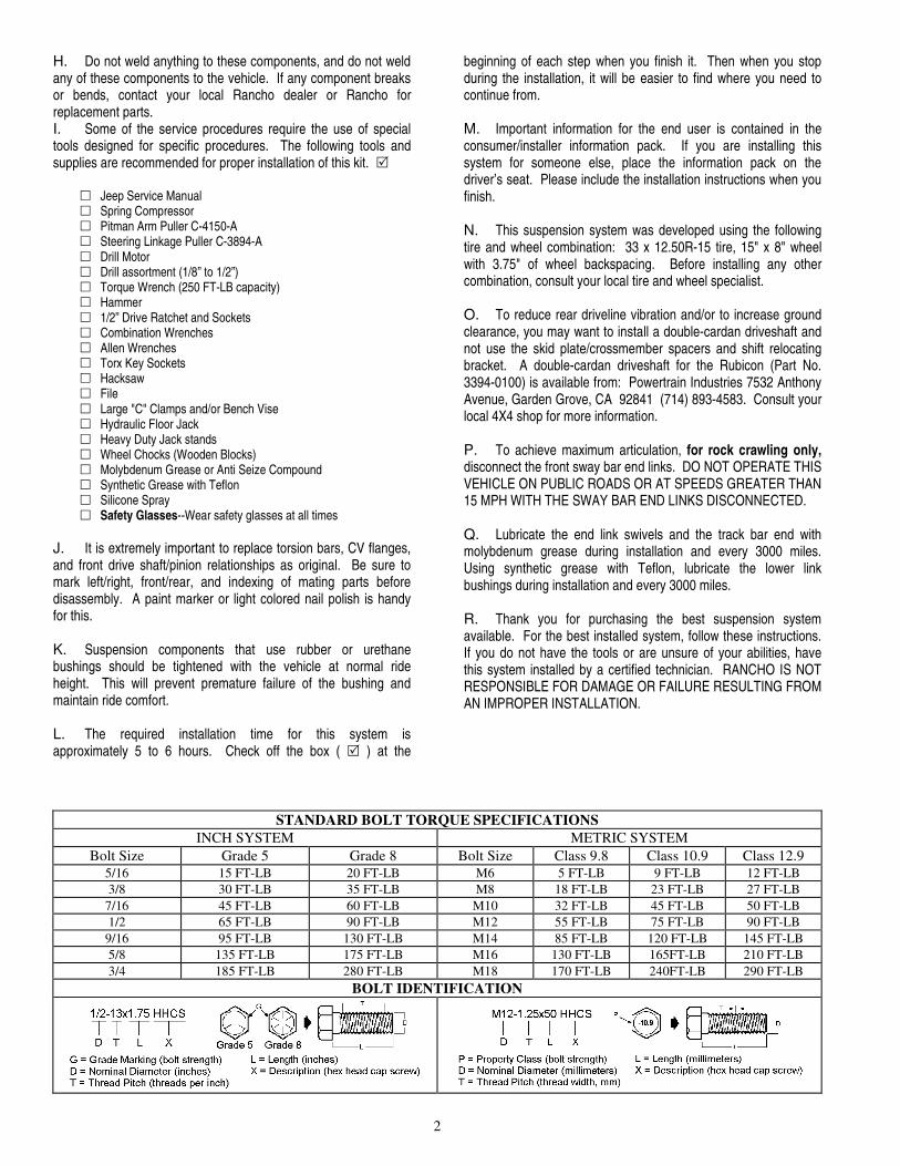
STANDARD BOLT TORQUE SPECIFICATIONS INCH SYSTEM METRIC SYSTEM
Bolt Size Grade 5 Grade 8 Bolt Size Class 9.8 Class 10.9 Class 12.9 5/16 15 FT-LB 20 FT-LB M6 5 FT-LB 9 FT-LB 12 FT-LB 3/8 30 FT-LB 35 FT-LB M8 18 FT-LB 23 FT-LB 27 FT-LB
7/16 45 FT-LB 60 FT-LB M10 32 FT-LB 45 FT-LB 50 FT-LB 1/2 65 FT-LB 90 FT-LB M12 55 FT-LB 75 FT-LB 90 FT-LB
9/16 95 FT-LB 130 FT-LB M14 85 FT-LB 120 FT-LB 145 FT-LB 5/8 135 FT-LB 175 FT-LB M16 130 FT-LB 165FT-LB 210 FT-LB 3/4 185 FT-LB 280 FT-LB M18 170 FT-LB 240FT-LB 290 FT-LB
BOLT IDENTIFICATION
3
PARTS LIST P/N DESCRIPTION QTY. 130019 Rear Track Bar Bracket 1 170081 Right Brake Hose 1 170082 Left Brake Hose 1 176083 End Link Center 2 176084 End Link Bottom 2 176085 End Link Bracket 2 176086 Track Bar 1 176088 Rear End Link 2 176089 Front Bump Stop Perch 2 176080 Suspension Link 4 420027 Rear Bump Stop Spacer 2 602612 Track bar End (ball joint) 1 602615 End Link Swivel 2 615 Front Coil Spring (6506 only) 2 616 Rear Coil Spring (6506 only) 2 7727 Pitman Arm 1 860072 Rear Track Bar Relocation Kit 1 420026 Sleeve 1 7/16-14x1.0 HHCS 1 7/16-14 Stover Nut 1 7/16 SAE Washer 2 M12-1.75x70 HHCS 2 M12-1.75 Nut 2 SAE Washer 4 3/8-16x1.0 HHCS 1 3/8-16 Stover Nut 1 3/8 SAE Washer 2 860086 Gasket Kit 1 170078 Brake Line Gasket 4 860155 Rear End Link Hardware Kit 1 420088 Sleeve, Rear End Link 4 545 Bushing 4 7/16-20x2.5 HHCS 4 7/16-20 Stover Nut 4 7/16 SAE Washer 4 7/16 USS Washer 6 860157 Front Track Bar Hardware Kit 1 420086 Sleeve 1 520086 Bushing 2 3/8-16x1.5 HHTS 2 3/4-16 Jam Nut 1 Cotter Pin 1
P/N DESCRIPTION QTY. 860160 Shift Relocation Kit 1 176090 Bracket 1 1/4-20x.75 BHCS 4 1/4 SAE Washer 4 1/4-20 Nyloc Nut 4 Thread Lock 2 860161 Skid Plate Spacer Kit 1 176091 Skid Plate Spacer 6 176092 Skid Plate Shim 6 1/2 Cone Washer 6 1/2-13x2.5 FSHCS 6 M10-1.50x70 HHCS 2 10mm Lock Washer 2 860218 Articulation Bushing Kit 1 420080 Sleeve 8 520080 Bushing 16 860070 Shim Kit 1 Washer 16 860483 Skid Plate Hardware Kit 1 M12-1.75 x 65 HHCS 6 12mm Washer 6 860561 Quick Disconnect Hardware Kit 1 420084 Sleeve, Front End Link 2 545 Bushing 2 770057 Lynch Pin Assembly 2 3/4 Rubber Washer 4 10mm Washer 2 1/2-20 x 1.75 HHCS 2 1/2-20 x 2.75 HHCS 2 1/2-20 Nyloc Nut 4 1/2 SAE Washer 4 1/2 USS Washer 4 94180 Information Pack 1 780281 Rancho Decal 1 88056 Instructions 1 94119 Consumer/Warranty Information 1 94177 Warning Sticker 1 Included in RS6504 only 694 Front Spring 2 698 Rear Spring 2 Included in RS6505 only 615 Front Spring 2 616 Rear Spring 2
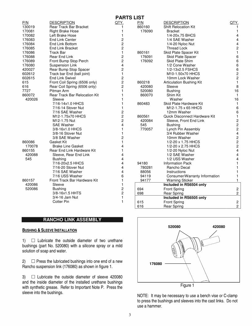
RANCHO LINK ASSEMBLY BUSHING & SLEEVE INSTALLATION 1) � Lubricate the outside diameter of two urethane bushings (part No. 520080) with a silicone spray or a mild solution of soap and water. 2) � Press the lubricated bushings into one end of a new Rancho suspension link (176080) as shown in figure 1. 3) � Lubricate the outside diameter of sleeve 420080 and the inside diameter of the installed urethane bushings with synthetic grease. Refer to Important Note P. Press the sleeve into the bushings.
Figure 1
NOTE: It may be necessary to use a bench vise or C-clamp to press the bushings and sleeves into the cast links. Do not use a hammer.
176080
420080 520080
4
4) � Slowly apply grease to each end of the cast links (through the grease fitting) with a grease gun. Stop when the grease begins to appear around the edges of the bushings. Do not force the bushings out of the link. 5) � Repeat steps 1 through 4 for the remaining cast link ends, bushings, and sleeves.
FRONT SUSPENSION TRACK BAR & COIL SPRING REMOVAL 1) � Park vehicle on a level surface and set the parking brake. Center front wheels and chock rear wheels. 2) � Utilizing a straight edge, measure the horizontal distance between the outer edge of each front tire and the vehicle body (at top edge of fender well). Left Side:_________ Right Side:_________ 3) � Remove the cotter pin and nut from the ball stud end of the track bar at the frame rail bracket. Separate the ball stud from the bracket with the recommended puller tool. See figure 2.
Figure 2
4) � Remove the bolt and flag nut from the axle bracket. Remove the track bar. 5) � From inside the engine compartment, remove the upper stud nut, retainer and grommet from both front shock absorbers. 6) � If applicable, remove the bolts attaching the automatic transmission skid plate to the frame rails and the transfer case cross member (Do not use an impact wrench). Remove the skid plate.
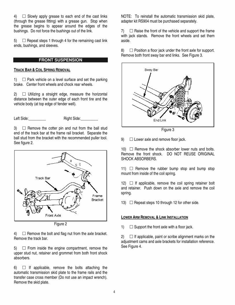
NOTE: To reinstall the automatic transmission skid plate, adapter kit RS904 must be purchased separately. 7) � Raise the front of the vehicle and support the frame with jack stands. Remove the front wheels and set them aside. 8) � Position a floor jack under the front axle for support. Remove both front sway bar end links. See Figure 3.
Figure 3
9) � Lower axle and remove floor jack. 10) � Remove the shock absorber lower nuts and bolts. Remove the front shock. DO NOT REUSE ORIGINAL SHOCK ABSORBERS. 11) � Remove the rubber bump stop and bump stop mount from inside of the coil spring. 12) � If applicable, remove the coil spring retainer bolt and retainer. Push down on the axle and remove the coil spring. 13) � Repeat steps 10 through 12 for other side. LOWER ARM REMOVAL & LINK INSTALLATION 1) � Support the front axle with a floor jack. 2) � If applicable, paint or scribe alignment marks on the adjustment cams and axle brackets for installation reference. See Figure 4.
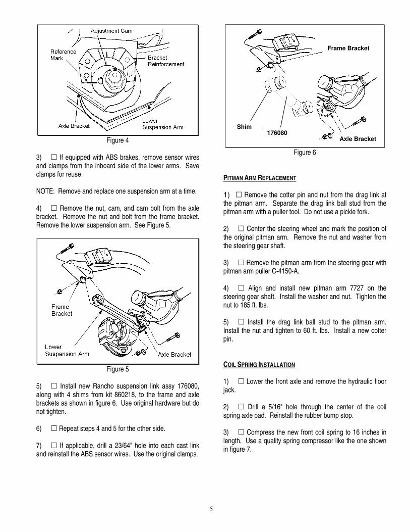
5
Figure 4
3) � If equipped with ABS brakes, remove sensor wires and clamps from the inboard side of the lower arms. Save clamps for reuse. NOTE: Remove and replace one suspension arm at a time. 4) � Remove the nut, cam, and cam bolt from the axle bracket. Remove the nut and bolt from the frame bracket. Remove the lower suspension arm. See Figure 5.
Figure 5
5) � Install new Rancho suspension link assy 176080, along with 4 shims from kit 860218, to the frame and axle brackets as shown in figure 6. Use original hardware but do not tighten. 6) � Repeat steps 4 and 5 for the other side. 7) � If applicable, drill a 23/64" hole into each cast link and reinstall the ABS sensor wires. Use the original clamps.
Figure 6
PITMAN ARM REPLACEMENT 1) � Remove the cotter pin and nut from the drag link at the pitman arm. Separate the drag link ball stud from the pitman arm with a puller tool. Do not use a pickle fork. 2) � Center the steering wheel and mark the position of the original pitman arm. Remove the nut and washer from the steering gear shaft. 3) � Remove the pitman arm from the steering gear with pitman arm puller C-4150-A. 4) � Align and install new pitman arm 7727 on the steering gear shaft. Install the washer and nut. Tighten the nut to 185 ft. lbs. 5) � Install the drag link ball stud to the pitman arm. Install the nut and tighten to 60 ft. lbs. Install a new cotter pin. COIL SPRING INSTALLATION 1) � Lower the front axle and remove the hydraulic floor jack. 2) � Drill a 5/16" hole through the center of the coil spring axle pad. Reinstall the rubber bump stop. 3) � Compress the new front coil spring to 16 inches in length. Use a quality spring compressor like the one shown in figure 7.
Link 176080
Grease Fitting
Frame Bracket
Shims
Axle Bracket
Shim 176080

6
Figure 7
4) � Place bump stop perch 176089 inside the compressed spring as you install the spring into the upper and lower spring pockets. Carefully remove the spring compressor. 5) � Rotate spring so pig tail end fits back in spring pocket. Attach the bump stop perch to the axle pad with the self-tapping screw from kit 860157. 6) � Repeat steps 2 through 5 for other side. BRAKE HOSE REPLACEMENT NOTE: To keep the brake bleeding process to just the front calipers, do not allow the brake fluid to drain completely from the master cylinder reservoir. 1) � Separate the left front brake hose from the brake tube and the frame rail. Plug tube to prevent brake fluid leakage. 2) � Remove the brake hose from the caliper. Discard copper washers. 3) � Attach left brake hose RS170082 to the caliper with NEW copper washers from kit RS860086, and the original bolt. See figure 8. Tighten the bolt to 23 ft.-lbs.
Figure 8
4) � Attach the new brake hose to the frame and brake tube. Tighten securely. 5) � Repeat steps 1 through 4 to install right front brake hose RS170081. 6) � Refill the master cylinder reservoir with approved brake fluid and bleed the front brakes as follows:
• Attach a clear hose to the right front caliper bleeder screw and immerse the other end into a container of clean brake fluid.
• Loosen the bleeder valve on the caliper. • Have an assistant push the brake pedal down and then
hold. • Tighten the bleeder valve and slowly release the pedal. • Repeat the procedure until all air is purged from the
caliper. • Attach the hose and container to the left front caliper and
repeat the bleeding process. Refill the brake master cylinder reservoir as necessary.
SWAY BAR END LINK ASSEMBLY 1) � Apply silicone lubricant and press a bushing from kit 860561 into a front end link bottom socket (176084). 2) � Apply silicone lubricant and press a sleeve from kit 860561 into the installed bushing. 3) � Install a rubber washer from kit 860561 onto each end of center section 176083. 4) � Connect the bottom socket assembly to a top swivel (602615) with the center section. Insert a set of locking pins (770057) as shown in figure 9.
Figure 9
7
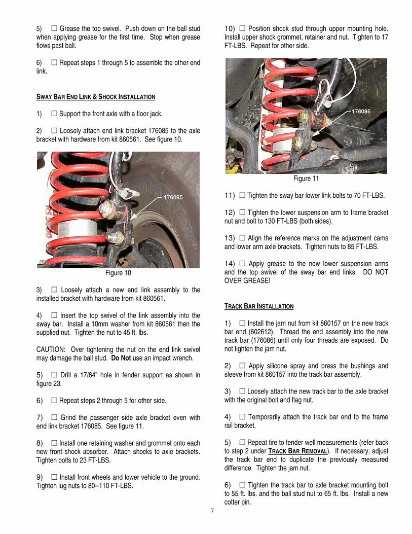
5) � Grease the top swivel. Push down on the ball stud when applying grease for the first time. Stop when grease flows past ball. 6) � Repeat steps 1 through 5 to assemble the other end link. SWAY BAR END LINK & SHOCK INSTALLATION 1) � Support the front axle with a floor jack. 2) � Loosely attach end link bracket 176085 to the axle bracket with hardware from kit 860561. See figure 10.
Figure 10
3) � Loosely attach a new end link assembly to the installed bracket with hardware from kit 860561. 4) � Insert the top swivel of the link assembly into the sway bar. Install a 10mm washer from kit 860561 then the supplied nut. Tighten the nut to 45 ft. lbs. CAUTION: Over tightening the nut on the end link swivel may damage the ball stud. Do Not use an impact wrench. 5) � Drill a 17/64” hole in fender support as shown in figure 23. 6) � Repeat steps 2 through 5 for other side. 7) � Grind the passenger side axle bracket even with end link bracket 176085. See figure 11. 8) � Install one retaining washer and grommet onto each new front shock absorber. Attach shocks to axle brackets. Tighten bolts to 23 FT-LBS. 9) � Install front wheels and lower vehicle to the ground. Tighten lug nuts to 80--110 FT-LBS.
10) � Position shock stud through upper mounting hole. Install upper shock grommet, retainer and nut. Tighten to 17 FT-LBS. Repeat for other side.
Figure 11
11) � Tighten the sway bar lower link bolts to 70 FT-LBS. 12) � Tighten the lower suspension arm to frame bracket nut and bolt to 130 FT-LBS (both sides). 13) � Align the reference marks on the adjustment cams and lower arm axle brackets. Tighten nuts to 85 FT-LBS. 14) � Apply grease to the new lower suspension arms and the top swivel of the sway bar end links. DO NOT OVER GREASE! TRACK BAR INSTALLATION 1) � Install the jam nut from kit 860157 on the new track bar end (602612). Thread the end assembly into the new track bar (176086) until only four threads are exposed. Do not tighten the jam nut. 2) � Apply silicone spray and press the bushings and sleeve from kit 860157 into the track bar assembly. 3) � Loosely attach the new track bar to the axle bracket with the original bolt and flag nut. 4) � Temporarily attach the track bar end to the frame rail bracket. 5) � Repeat tire to fender well measurements (refer back to step 2 under TRACK BAR REMOVAL). If necessary, adjust the track bar end to duplicate the previously measured difference. Tighten the jam nut. 6) � Tighten the track bar to axle bracket mounting bolt to 55 ft. lbs. and the ball stud nut to 65 ft. lbs. Install a new cotter pin.
8
REAR SUSPENSION TRACK BAR & COIL SPRING REMOVAL 1) � Chock front wheels. Disconnect and remove the rear sway bar end links. 2) � Disconnect the track bar from the frame bracket. See figure 12. 3) � Raise the rear of the vehicle and support the frame with jack stands. Remove the rear wheels. 4) � Separate the track bar from the axle bracket. Remove the track Bar. See Figure 11.
Figure 11
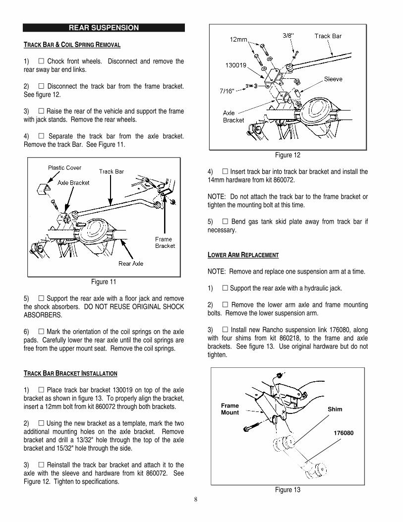
5) � Support the rear axle with a floor jack and remove the shock absorbers. DO NOT REUSE ORIGINAL SHOCK ABSORBERS. 6) � Mark the orientation of the coil springs on the axle pads. Carefully lower the rear axle until the coil springs are free from the upper mount seat. Remove the coil springs. TRACK BAR BRACKET INSTALLATION 1) � Place track bar bracket 130019 on top of the axle bracket as shown in figure 13. To properly align the bracket, insert a 12mm bolt from kit 860072 through both brackets. 2) � Using the new bracket as a template, mark the two additional mounting holes on the axle bracket. Remove bracket and drill a 13/32" hole through the top of the axle bracket and 15/32" hole through the side. 3) � Reinstall the track bar bracket and attach it to the axle with the sleeve and hardware from kit 860072. See Figure 12. Tighten to specifications.
Figure 12
4) � Insert track bar into track bar bracket and install the 14mm hardware from kit 860072. NOTE: Do not attach the track bar to the frame bracket or tighten the mounting bolt at this time. 5) � Bend gas tank skid plate away from track bar if necessary. LOWER ARM REPLACEMENT NOTE: Remove and replace one suspension arm at a time. 1) � Support the rear axle with a hydraulic jack. 2) � Remove the lower arm axle and frame mounting bolts. Remove the lower suspension arm. 3) � Install new Rancho suspension link 176080, along with four shims from kit 860218, to the frame and axle brackets. See figure 13. Use original hardware but do not tighten.
Figure 13
Link 176080
Grease Fitting
Frame Mount Shim
176080
9
NOTE: Install two shims at each mounting point, one on either side of the bushing assembly. Also, position the cast link so that the grease fittings are accessible. 4) � Repeat steps 2 and 3 for the other side. BUMP STOP SPACER & COIL SPRING INSTALLATION 1) � Remove the rubber bump stop and bump stop bracket from the upper spring mount. 2) � Insert Rancho spacer 420027 and reinstall the bracket with the 10mm hardware from kit 860161. Insert the bump stop into the bump stop bracket. See figure 14.
Figure 14
3) � Repeat steps 1 & 2 for other side. 4) � Lower rear axle and position the new coil springs onto the axle pads. Align springs with reference marks. Raise the axle until the spring seat in the upper mounts. NOTE: When installing coil springs, make sure that the rubber damper is positioned in the upper mount and the small egg-shaped coil end is at the top. 5) � Install new Rancho rear shocks to the upper frame rail. Tighten mounting bolts to 23 FT-LBS. 6) � Loosely attach shocks to the axle brackets. 7) � Install wheels and lower vehicle to the ground. Do not remove wheel chocks. Tighten lug nuts to 80-110 FT-LBS.
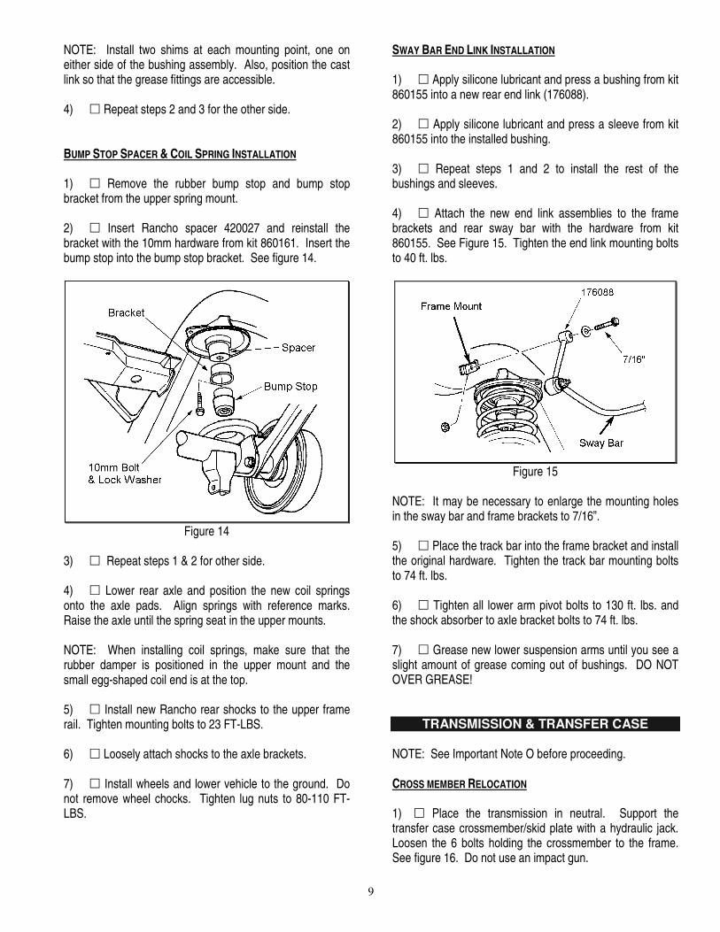
SWAY BAR END LINK INSTALLATION 1) � Apply silicone lubricant and press a bushing from kit 860155 into a new rear end link (176088). 2) � Apply silicone lubricant and press a sleeve from kit 860155 into the installed bushing. 3) � Repeat steps 1 and 2 to install the rest of the bushings and sleeves. 4) � Attach the new end link assemblies to the frame brackets and rear sway bar with the hardware from kit 860155. See Figure 15. Tighten the end link mounting bolts to 40 ft. lbs.
Figure 15
NOTE: It may be necessary to enlarge the mounting holes in the sway bar and frame brackets to 7/16”. 5) � Place the track bar into the frame bracket and install the original hardware. Tighten the track bar mounting bolts to 74 ft. lbs. 6) � Tighten all lower arm pivot bolts to 130 ft. lbs. and the shock absorber to axle bracket bolts to 74 ft. lbs. 7) � Grease new lower suspension arms until you see a slight amount of grease coming out of bushings. DO NOT OVER GREASE!
TRANSMISSION & TRANSFER CASE NOTE: See Important Note O before proceeding. CROSS MEMBER RELOCATION 1) � Place the transmission in neutral. Support the transfer case crossmember/skid plate with a hydraulic jack. Loosen the 6 bolts holding the crossmember to the frame. See figure 16. Do not use an impact gun.
10
Figure 16
2) � Remove 3 bolts on one side and carefully lower the cross member/skid plate. 3) � Place 3 spacers from kit 860161 between the cross member and the frame with the conical end of the spacer facing down. See figure 18a. For vehicles with an automatic transmission, add 3 shims. 4) � If flat head screws were removed, install a conical washer and apply thread lock to 3 flat head screws from kit 860161. Insert the screws through the crossmember, spacers, and into the frame. See figure 17.
Figure 17
5) � If hex head screws were removed, install the hardware from kit 860483. See figure 18. 6) � Repeat steps 3 through 6 for the other side of the cross member. Tighten all bolts to 45 FT-LBS.
Figure 18
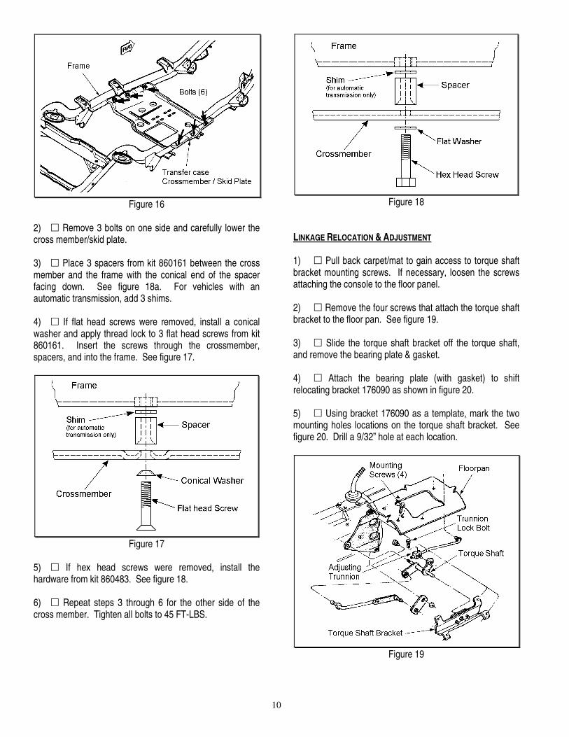
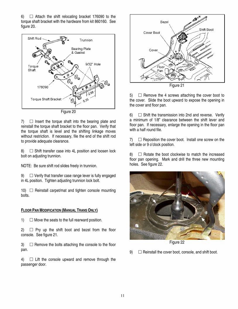
LINKAGE RELOCATION & ADJUSTMENT 1) � Pull back carpet/mat to gain access to torque shaft bracket mounting screws. If necessary, loosen the screws attaching the console to the floor panel. 2) � Remove the four screws that attach the torque shaft bracket to the floor pan. See figure 19. 3) � Slide the torque shaft bracket off the torque shaft, and remove the bearing plate & gasket. 4) � Attach the bearing plate (with gasket) to shift relocating bracket 176090 as shown in figure 20. 5) � Using bracket 176090 as a template, mark the two mounting holes locations on the torque shaft bracket. See figure 20. Drill a 9/32” hole at each location.
Figure 19
11
6) � Attach the shift relocating bracket 176090 to the torque shaft bracket with the hardware from kit 860160. See figure 20.
Figure 20
7) � Insert the torque shaft into the bearing plate and reinstall the torque shaft bracket to the floor pan. Verify that the torque shaft is level and the shifting linkage moves without restriction. If necessary, file the end of the shift rod to provide adequate clearance. 8) � Shift transfer case into 4L position and loosen lock bolt on adjusting trunnion. NOTE: Be sure shift rod slides freely in trunnion. 9) � Verify that transfer case range lever is fully engaged in 4L position. Tighten adjusting trunnion lock bolt. 10) � Reinstall carpet/mat and tighten console mounting bolts. FLOOR PAN MODIFICATION (MANUAL TRANS ONLY) 1) � Move the seats to the full rearward position. 2) � Pry up the shift boot and bezel from the floor console. See figure 21. 3) � Remove the bolts attaching the console to the floor pan. 4) � Lift the console upward and remove through the passenger door.
Figure 21
5) � Remove the 4 screws attaching the cover boot to the cover. Slide the boot upward to expose the opening in the cover and floor pan. 6) � Shift the transmission into 2nd and reverse. Verify a minimum of 1/8” clearance between the shift lever and floor pan. If necessary, enlarge the opening in the floor pan with a half round file. 7) � Reposition the cover boot. Install one screw on the left side or 9 o’clock position. 8) � Rotate the boot clockwise to match the increased floor pan opening. Mark and drill the three new mounting holes. See figure 22.
Figure 22
9) � Reinstall the cover boot, console, and shift boot.
12
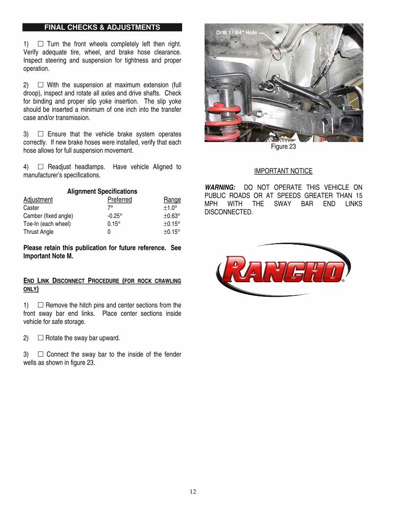
FINAL CHECKS & ADJUSTMENTS 1) � Turn the front wheels completely left then right. Verify adequate tire, wheel, and brake hose clearance. Inspect steering and suspension for tightness and proper operation. 2) � With the suspension at maximum extension (full droop), inspect and rotate all axles and drive shafts. Check for binding and proper slip yoke insertion. The slip yoke should be inserted a minimum of one inch into the transfer case and/or transmission. 3) � Ensure that the vehicle brake system operates correctly. If new brake hoses were installed, verify that each hose allows for full suspension movement. 4) � Readjust headlamps. Have vehicle Aligned to manufacturer’s specifications.
Alignment Specifications Adjustment Preferred Range Caster 7° ±1.0° Camber (fixed angle) -0.25° ±0.63° Toe-In (each wheel) 0.15° ±0.15° Thrust Angle 0 ±0.15° Please retain this publication for future reference. See Important Note M. END LINK DISCONNECT PROCEDURE (FOR ROCK CRAWLING ONLY) 1) � Remove the hitch pins and center sections from the front sway bar end links. Place center sections inside vehicle for safe storage. 2) � Rotate the sway bar upward. 3) � Connect the sway bar to the inside of the fender wells as shown in figure 23.
Figure 23
IMPORTANT NOTICE
WARNING: DO NOT OPERATE THIS VEHICLE ON PUBLIC ROADS OR AT SPEEDS GREATER THAN 15 MPH WITH THE SWAY BAR END LINKS DISCONNECTED.