Embed Size (px)
Citation preview
80902Rev 01/29/20
Page 1 of 7www.bmracing.comTechnical Support (866) 464-6553
INSTALLATION INSTRUCTIONS FOR
PRO GATE SHIFTERPart No. 80902
Rear cable exit, 4-speed GM automaticsw/forward shift pattern
INTRODUCTIONThe B&M Pro Gate shifter is an externally-gated race shifter. This model features a rear-exit cable, and is suitable for GM four-speed automatic transmissions with forward-pattern valve bodies.
The compact and lightweight design is constructed with 304 stainless steel, 1018 steel, rugged nylon side covers and other high-grade materials.
The result is a hard-core race shifter that provides short, positive, dependable shifts, with little to no maintenance required — which makes the Pro Gate especially suited for off-road racing.
NOTE: This shifter is not recommended for street use, as it does not include neutral safety or back-up light switches.
Before starting, please take the time to read and understand these instructions.
Also, use the parts list to verify your kit’s contents. In the unlikely event that any parts are missing, please contact B&M Technical Support for replacements.
NOTES• Installation requires better-than-average mechanical knowl-
edge and skills. If this job is beyond your abilities, seek the services of a qualified technician.
• The shifter mechanism is precision-assembled at our factory. Any modification or disassembly of the shifter will void its warranty, and can cause it to malfunction. Disassemble items only where specified in the instructions.
• Installation of this shifter may require modification or com-plete removal of your vehicle’s console, depending on the space available in your vehicle.
• If you do not understand any part of these instructions, please call B&M Technical Support at (866) 464-6553 for assistance.
• The shifter cable in this kit is 5 feet long. Different length shifter cables are available separately from B&M, if required.
PARTS LIST
DESCRIPTION QTYSHIFTER ASSEMBLY, PRO GATE 1CABLE, SHIFTER, 5' 1E-CLIP, 1/4" ID 1NUT, NYLOCK 1/4-20 1BOLT, 1/4-20 × 5/8" 1BOLT, 1/4-20 × 1-1/4" 4NUT, 1/4-20 4WASHER, SPLIT LOCK 1/4" 4SELECTOR LEVER, GM 1BRACKET, CABLE 1BOLT, M8-1.25 × 25 2WASHER, FLAT 5/16" 2SPACER, 7/16" I.D. × 1/4" L 2SWIVEL, CABLE 1JAM NUT, 10-32 (COMES INSTALLED ON CABLE END) 1PIN, COTTER 1/16" × 1" 1
80902Rev 01/29/20
Page 2 of 7www.bmracing.comTechnical Support (866) 464-6553
SAFETY WARNINGS• WORK SAFELY! For maximum safety, perform this installation
on a clean, level surface, with the engine turned off. Chock the wheels to prevent vehicle movement. To avoid bodily injury or vehicle damage, do not begin work until you are confident that the vehicle is safely secured and will not move.
• AVOID SERIOUS INJURY OR DEATH BY CRUSHING! If you have to raise the vehicle to work under it, securely support it on a lift or jack stands. NEVER work under a vehicle that is supported only by jacks!
• WARNING: This B&M performance shifter uses a cable to shift the transmission only; it is NOT intended or designed to operate a locking steering column! If your vehicle has a locking steering column, it must be modified or disabled to prevent the steering from unintentionally locking up while driving. If you are not comfortable making this modification, or if you don’t understand this warning, seek the services of a qualified technician for the safe installation of this shifter.
INSTALLATION1. Remove the stock shift linkage.
Column Shifters: Remove all rods, levers or cables from the column and the transmission. Retain the selector lever nut. Place the column shift lever in the PARK position. Remove the pin holding the shift lever in the column and remove the lever assembly. If your vehicle is equipped with a locking steering column, secure the column lock lever in the full up position. (See WARNING re. locking steering columns, above.)
Console Shifters: Remove the shifter mechanism from the console. Disconnect the rod or cable, and the selector lever, from the transmission. Retain the selector lever nut. Remove the cable bracket if equipped. If there is a cable or linkage from the console shifter or transmission to the steering column lock, it must be blocked in the PARK position as described above.
CAUTION: The shifter and cable must be assembled before positioning the shifter in your vehicle. This is to ensure proper cable clearance at the rear of the shifter before permanently mounting it in the vehicle. Mounting the shifter without the cable attached can cause interference with the interior vehicle components, poor cable routing, and cable binding, resulting in poor shifter operation or cable damage.
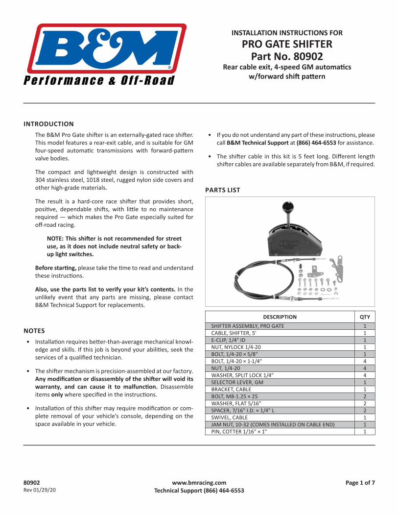
2. Disassemble the shifter: Remove the knob and jam nut from the shift lever. Remove the 3 countersunk screws from the bottom of each side of the shifter. Then remove the assembled gate plate and side cover from the shifter base.
3. Assemble the shifter and cable. At the front (eye-end) of the cable, pull the two plastic dust boots all the way forward. Insert the cable through the notch in the shifter body. Secure the cable eye to the shifter pin with the E-clip. Then secure the cable housing tab to the shifter base with the 1/4-20 × 5/8" bolt and lock nut. Finally, push both plastic dust boots back over their respective joints.
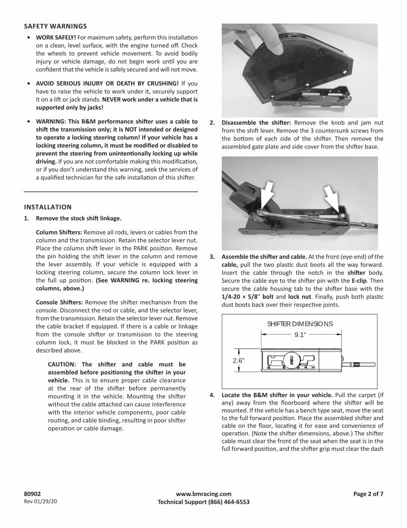
4. Locate the B&M shifter in your vehicle. Pull the carpet (if any) away from the floorboard where the shifter will be mounted. If the vehicle has a bench type seat, move the seat to the full forward position. Place the assembled shifter and cable on the floor, locating it for ease and convenience of operation. (Note the shifter dimensions, above.) The shifter cable must clear the front of the seat when the seat is in the full forward position, and the shifter grip must clear the dash
2.6"
9.1"SHIFTER DIMENSIONS
80902Rev 01/29/20
Page 3 of 7www.bmracing.comTechnical Support (866) 464-6553
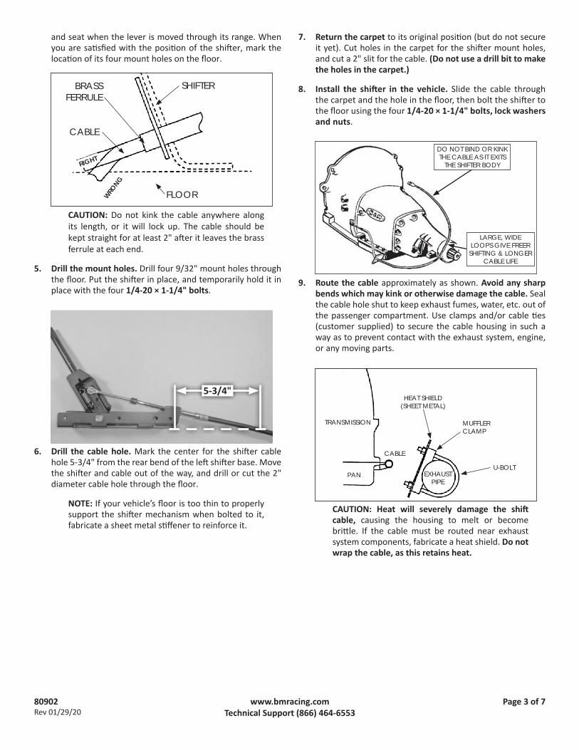
and seat when the lever is moved through its range. When you are satisfied with the position of the shifter, mark the location of its four mount holes on the floor.
CAUTION: Do not kink the cable anywhere along its length, or it will lock up. The cable should be kept straight for at least 2" after it leaves the brass ferrule at each end.
5. Drill the mount holes. Drill four 9/32" mount holes through the floor. Put the shifter in place, and temporarily hold it in place with the four 1/4-20 × 1-1/4" bolts.
6. Drill the cable hole. Mark the center for the shifter cable hole 5-3/4" from the rear bend of the left shifter base. Move the shifter and cable out of the way, and drill or cut the 2" diameter cable hole through the floor.
NOTE: If your vehicle’s floor is too thin to properly support the shifter mechanism when bolted to it, fabricate a sheet metal stiffener to reinforce it.
7. Return the carpet to its original position (but do not secure it yet). Cut holes in the carpet for the shifter mount holes, and cut a 2" slit for the cable. (Do not use a drill bit to make the holes in the carpet.)
8. Install the shifter in the vehicle. Slide the cable through the carpet and the hole in the floor, then bolt the shifter to the floor using the four 1/4-20 × 1-1/4" bolts, lock washers and nuts.
9. Route the cable approximately as shown. Avoid any sharp bends which may kink or otherwise damage the cable. Seal the cable hole shut to keep exhaust fumes, water, etc. out of the passenger compartment. Use clamps and/or cable ties (customer supplied) to secure the cable housing in such a way as to prevent contact with the exhaust system, engine, or any moving parts.
CAUTION: Heat will severely damage the shift cable, causing the housing to melt or become brittle. If the cable must be routed near exhaust system components, fabricate a heat shield. Do not wrap the cable, as this retains heat.
WRONG
RIGHT
CABLE
SHIFTERBRASS FERRULE
FLOOR
DO NOT BIND OR KINK THE CABLE AS IT EXITS
THE SHIFTER BODY
LARGE, WIDE LOOPS GIVE FREER
SHIFTING & LONGER CABLE LIFE
TRANSMISSION
PAN
CABLE
EXHAUSTPIPE
HEAT SHIELD(SHEET METAL)
MUFFLER CLAMP
U-BOLT
5-3/4"

80902Rev 01/29/20
Page 4 of 7www.bmracing.comTechnical Support (866) 464-6553
10. Ensure there is no debris in the shifter mechanism, then reinstall the assembled gate plate and side covers on the shifter base, using 3 screws along each side.
CAUTION: It may be necessary to loosen the top screws about a half turn, to allow the side covers to slip over the shifter base. If so, ensure that the two spacers remain oriented correctly, with the bumps touching the inside of the gate plate.
NOTE: The instruction photos show the transmission on a work bench, not installed in a vehicle.
11. Reinstall the jam nut (flats down) and shift knob. Orient the knob as desired, then tighten the jam nut.
12. At the transmission, install the B&M selector lever using the stock selector lever nut, and tighten the nut to 23 ft-lbs torque. The lever should travel smoothly back and forth, with a positive “click” in each detent.
13. Remove the two oil pan bolts to the rear of the selector shaft. Then determine which two holes on the cable bracket will be used on your transmission, and install the bracket using the two M8-1.25 × 25 bolts and 5/16" flat washers.
A. For stamped sheet-metal (stock) pans, use the two spacers between the pan and bracket.
BUMPBUMP

80902Rev 01/29/20
Page 5 of 7www.bmracing.comTechnical Support (866) 464-6553
B. For cast aluminum pans:• The bracket may need to be trimmed to fit. (Example
shown above is on a 3-speed.)• The spacers are not used.
Tighten the bolts to 12-13 ft-lbs torque.
CAUTION: Do not over-tighten the bolts, as this can damage the pan gasket.
14. Attach the shifter cable to the cable bracket: First remove the small jam nut, two plastic dust boots, and one large nut and lock washer from the cable. Then insert the cable through the cable bracket, reinstall the lock washer and nut on the cable (loosely, to allow room for adjustment), and reinstall the two dust boots.
15. Thread the swivel onto the cable to about the middle of the threaded section, then reinstall (but do not tighten) the jam nut.
16. At the transmission, manually move the selector lever to the DRIVE detent (that is, 3 clicks forward from PARK, or fully rearward). Then in the vehicle, move the shifter handle to DRIVE.
17. Adjust the large cable nuts until the swivel slides freely in and out of hole F in the selector lever. Gradually tighten the nuts against the bracket, while continuing to check the fit of the swivel in the selector lever.
CAUTION: The shifter will not operate properly unless hole F in the selector lever is used.
18. When the swivel slips freely in and out of the selector lever, snug the jam nut.
F
REMOVE
EXAMPLE: BRACKET TRIMMED TO FIT ALUMINUM PAN (3-SPD)
LARGE NUTS
80902Rev 01/29/20
Page 6 of 7www.bmracing.comTechnical Support (866) 464-6553
19. With the swivel still in the selector lever, move the shifter into REVERSE. Verify that the swivel still slips freely in and out of the selector lever. If not, adjust the large cable nuts (and the swivel, if necessary), until it does.
20. With the swivel still in the selector lever, move the shifter back through each gear position to SECOND, verifying that the swivel slips freely in and out of the lever in each position.
NOTE: It is not necessary to check swivel fit in PARK or FIRST (1) gears on 4-speed transmissions. Internal tension may interfere with proper adjustment in those positions. Checking swivel fit from REVERSE through SECOND is sufficient to verify proper adjustment.
CAUTION: If you encounter restricted movement or any other problem during this process, DO NOT FORCE THE SHIFTER. Doing so may damage the cable, the shifter and/or the transmission. Simply return to Step 17 and re-check each step.
When the swivel slips freely in and out of the selector lever from REVERSE through SECOND gear, the cable is correctly adjusted. Verify that the two large cable nuts, and the cable swivel jam nut, are tight.
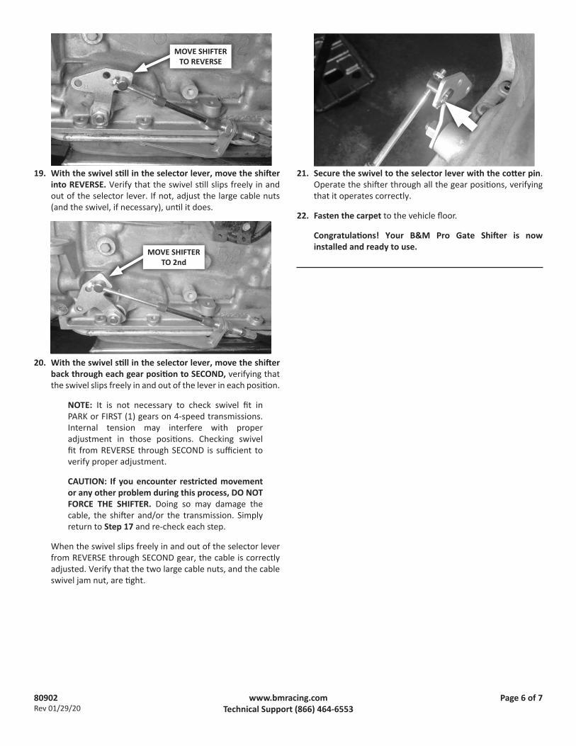
21. Secure the swivel to the selector lever with the cotter pin. Operate the shifter through all the gear positions, verifying that it operates correctly.
22. Fasten the carpet to the vehicle floor.
Congratulations! Your B&M Pro Gate Shifter is now installed and ready to use.MOVE SHIFTER
TO 2nd
MOVE SHIFTER TO REVERSE

80902Rev 01/29/20
Page 7 of 7www.bmracing.comTechnical Support (866) 464-6553
INSTALLATION CHECKLIST F Locking steering column lever is permanently fastened in the full up position (Step 1).
F Cable is connected to the shifter pin, and cable housing is securely fastened to the shifter base (Step 3).
F Shifter is convenient to reach and has ample room for driver’s hand throughout its range of motion (Step 4).
F Carpet covers floorboard holes (Step 7).
F Shifter is securely mounted to floorboard (Step 8).
F Cable is routed clear of exhaust system, engine, and any moving parts (Step 9).
F There is no debris in the shifter mechanism and the cover is installed (Step 10).
F Selector lever is securely installed on the transmission (Step 12).
F Cable bracket bolts are tightened to 12-13 ft-lbs torque (Step 13).
F Shifter is properly adjusted; cable boots are installed; cable nuts are tightened; swivel is secured with jam nut and cotter key (Steps 17-21).
CAUTION: If your shifter is not working properly, do not attempt to drive your car! Verify you have followed all instructions. If the shifter is broken or defective return it to your B&M dealer.
KEEP THESE INSTRUCTIONS FOR FUTURE REFERENCEB&M Performance & Off-Road maintains a highly-trained technical service department to answer your technical questions, provide additional product information and offer various recommendations.
B&M TECHNICAL SUPPORT: (866) 464-6553