Embed Size (px)
Citation preview

Doc.. 6001072Doc.. 6001072Doc.. 6001072Doc.. 6001072Rev BRev BRev BRev B
INSTALLATION INSTRUCTIONSINSTALLATION INSTRUCTIONSINSTALLATION INSTRUCTIONSINSTALLATION INSTRUCTIONSFOR THEFOR THEFOR THEFOR THE
"SSSS" AND AND AND AND "VVVV" MODEL MODEL MODEL MODELOVATION SYSTEMSOVATION SYSTEMSOVATION SYSTEMSOVATION SYSTEMS

Rev B Doc. 6001072 Page 1 of 28
IMPORTANT NOTICEMake sure you know the local telephone tariff arrangements before installing this system. Insome areas, the telephone company assumes responsibility for the phone lines up to eachresident's apartment. In that case, either the telephone company will assume responsibility forthe installation of the RJ71C jack to the telephone lines (as is normally the case), an additionalpair of wires will have to be run to and from each apartment, or the building owner will have toassume responsibility for the phone lines between the Ovation and their apartments.
• The Ovation system contains static sensitive parts. To avoid damage to the static sensitiveparts, ground the system and yourself while handling the board(s).
• Do not disconnect or reconnect anything from the system while the power is connected toany element of the system.
• Always use these instructions when you are installing the system or making changes to thesystem configuration.
TABLE OF CONTENTS
BASIC INSTALLATION RULES ..................................................................................... 3
PART 1 SYSTEM OVERVIEW ....................................................................................... 41. OVATION CONTROLLER .......................................................................................................... 42. LINE INTERFACE BOARDS (LIBs) ............................................................................................ 4
PART 2 SAMPLE INSTALLATION................................................................................. 61. SINGLE ENTRANCE .................................................................................................................. 62. MULTIPLE ENTRANCES ........................................................................................................... 7
PART 4 PHONE LINE INSTALLATION.......................................................................... 81. ARRANGING TELEPHONE INSTALLATION............................................................................. 82. INSTALLING RJ71C JACKS....................................................................................................... 83. LIB PLANNING FORM................................................................................................................ 9
PART 5 PULLING CABLES ......................................................................................... 101. SINGLE ENTRANCE ................................................................................................................ 102. MULTIPLE ENTRANCES ......................................................................................................... 12
PART 6 MOUNTING THE CABINETS.......................................................................... 141. OVATION "S" AND "V" MODEL CABINETS............................................................................. 142. LINE INTERFACE BOARD (LIB) HOUSINGS.......................................................................... 15
PART 7 SETTING LIB ADDRESSES ........................................................................... 161. SINGLE DECADE LIB SWITCH ............................................................................................... 162. THREE DECADE LIB SWITCH ................................................................................................ 17
PART 8 MAKING BASIC CONNECTIONS................................................................... 181. OVATION CONTROLLER CONNECTIONS............................................................................. 182. LIB CONNECTIONS ................................................................................................................. 20
PART 9 INSTALLING ADDITIONAL FEATURES ........................................................ 231. POSTAL LOCK ......................................................................................................................... 232. AUX OPEN/REQUEST FOR ACCESS..................................................................................... 233. DOOR POSITION SENSING.................................................................................................... 23
PART 10 TESTING AND ADJUSTING THE UNIT ....................................................... 241. VERIFYING CODE CAPABILITIES .......................................................................................... 242. ADJUSTING SIDETONE BALANCE......................................................................................... 243. VERIFYING TELEPHONE AND DOOR/GATE CONNECTIONS ............................................. 244. AUDIO ADJUSTMENT.............................................................................................................. 25
PART 11 GLOSSARY OF DIAGNOSTIC INDICATORS .............................................. 26
Page 2 of 28 Doc. 6001072 Rev B
1. OVATION CONTROLLER BOARD........................................................................................... 262. LINE INTERFACE BOARD (LIB) .............................................................................................. 26
FCC REQUIREMENTS................................................................................................. 271. INSTALLATION......................................................................................................................... 272. TYPE OF SERVICE .................................................................................................................. 273. TELEPHONE COMPANY PROCEDURES............................................................................... 274. IFF PROBLEMS ARISE ............................................................................................................ 275. RADIO FREQUENCY ............................................................................................................... 27
DOC REQUIREMENTS ................................................................................................ 28
IMPORTANT NOTICE
The Sentex Systems warranty on this system is conditioned upon Sentex Systemsbeing paid in full for this equipment. This warranty will not be honored until suchpayment is received by Sentex Systems.
In the interest of better serving its customers, Sentex is constantly in the process of upgrading itsproducts. Consequently, Sentex reserves the right to make changes in the products described in thismanual without notice and without obligation of Sentex to notify any persons of any such revisions orchanges. Additionally, Sentex make no representations of warranties with respect to this manual.
This document is protected by copyright, and may not be copied or adapted without the prior writtenconsent of Sentex Systems. This document contains information proprietary to Sentex and suchinformation may not be distributed without the prior written consent of Sentex. The firmware includedin the Sentex Ovation system as they relate to this documentation is also protected by copyright andcontain information proprietary to Sentex.
Copyright 2000All Rights Reserved
Sentex SystemsChatsworth, CA
Visit us at www.sentexsystems.com
Rev B Doc. 6001072 Page 3 of 28
BASIC INSTALLATION RULESPLEASE READ THIS SECTION VERY CAREFULLY BEFORE BEGINNING YOUR INSTALLATION.
In the sections that follow, detailed procedures are discussed for each step required to install theOvation system. In addition to these specific procedures, there are general rules which will help ensurethat your installation is done correctly and efficiently:
1. GROUND THE SYSTEM. The Ovation system contains parts which may be damaged by staticdischarge. This type of damage is not covered by Sentex's warranty. A proper earth groundconnected to the controller and LIB housings at the grounding points shown in Figures 12 and14 will significantly reduce the chances of damage or improper operation. The shields in thecables specified for all remote sensors and controls should also be connected to earth groundat the point shown in Figure 12.To be effective, the ground connection must be made by running 12 AWG copper wire to agood ground point (e.g., an electrical panel, a metallic cold water pipe that runs into the earth,or a grounding rod at least 10 feet in length that is driven into the earth) within 12 feet of thesystem. If you cannot meet these requirements, a ground will be of little value. Even if youhave a good earth ground, you should still try to discharge any static electricity before handlingthe circuit boards.
2. PROVIDE POWER FROM A DEDICATED SOURCE. The outlet(s) into which you plug thetransformers provided, or a DC power supply, should be wired to their own circuit breaker. Thiswill reduce the line noise introduced into system power and minimize the risk of having otherequipment interrupt system operation. Additionally, each Ovation controller, LIB housing, anddoor strike must have their own individual transformer.
3. DO NOT OVERLOAD THE TERMINAL BLOCKS. The terminal blocks used in the Ovationsystem are unpluggable and the pins are soldered into the boards. To connect your wires,remove the "head" from the correct terminals and open the screws. Insert the wire into thecorrect opening on the front and tighten the screw until the wire is held snugly. When you havemade all connections for a given "head," plug it back onto the pins designated for that terminalblock.
Stranded wire must be between 16 and 24 AWG. Solid wire must be between 18 and 24 AWG.This is the total thickness measurement, so if you are putting two wires in together, thecombined thickness must fall within this range. NEVER try to insert more than two wires perterminal.
4. ENSURE GOOD CONNECTIONS. A light tug on the wire will tell you if the connection issecure. When reconnecting system components, make sure all pins are straight on chips,connectors, and terminal block heads.
5. READ THE MARKINGS CAREFULLY. The connection points are marked on the boardsclearly. Before making any connection, be sure to read the marking and check it against thecorresponding figure in these instructions so that you understand the connection you aremaking.
6. TRAIN YOUR CUSTOMER. The Ovation system is very simple to program and use once ashort learning period has been completed. However, untrained programmers can causeserious problems for you and themselves. Ensure your customer has a copy of the manualProgramming and Use Instructions for all Ovation Systems (Doc. No. 6001012) to guide them.SPEND TIME NOW to train your customer on proper use of the system. It will save you andthem a lot of aggravation and inconvenience later.
Page 4 of 28 Doc. 6001072 Rev B
PART 1SYSTEM OVERVIEW
The Ovation telephone entry system connects directly to all of the resident phone lines in your building,allowing residents to be called without use of external telephone lines. As a result, the Ovation system doesnot generate telephone charges, either on a monthly or per call basis. The Ovation system is made up of twobasic components:
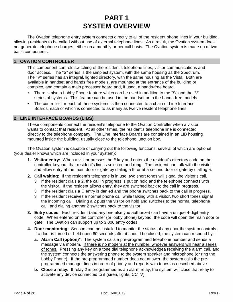
1. OVATION CONTROLLERThis component controls switching of the resident's telephone lines, visitor communications anddoor access. The "S" series is the simplest system, with the same housing as the Spectrum.The "V" series has an integral, lighted directory, with the same housing as the Vista. Both areavailable in handset and hands free models, are mounted at the entrance of the building orcomplex, and contain a main processor board and, if used, a hands-free board.
• There is also a Lobby Phone feature which can be used in addition to the "S" and the "V"series of systems. This feature can be used in the handset or in the hands-free models.
• The controller for each of these systems is then connected to a chain of Line InterfaceBoards, each of which is connected to as many as twelve resident telephone lines.
2. LINE INTERFACE BOARDS (LIBS)These components connect the resident's telephone to the Ovation Controller when a visitorwants to contact that resident. At all other times, the resident's telephone line is connecteddirectly to the telephone company. The Line Interface Boards are contained in an LIB housingmounted inside the building, usually close to the telephone junction box.
The Ovation system is capable of carrying out the following functions, several of which are optional(your dealer knows which are included in your system):
1. Visitor entry: When a visitor presses the # key and enters the resident's directory code on thecontroller keypad, that resident's line is selected and rung. The resident can talk with the visitorand allow entry at the main door or gate by dialing a 9, or at a second door or gate by dialling 5.
2. Call waiting: If the resident's telephone is in use, two short tones will signal the visitor's call.3 If the resident dials a 2, the call in progress is put on hold and the telephone connects with
the visitor. If the resident allows entry, they are switched back to the call in progress.3 If the resident dials a ∗ , entry is denied and the phone switches back to the call in progress.3 If the resident receives a normal phone call while talking with a visitor, two short tones signal
the incoming call. Dialing a 2 puts the visitor on hold and switches to the normal telephone call, and dialing another 2 switches back to the visitor.
3. Entry codes: Each resident (and any one else you authorize) can have a unique 4-digit entrycode. When entered on the controller (or lobby phone) keypad, the code will open the main door orgate. The Ovation can support up to 3,000 entry codes.
4. Door monitoring: Sensors can be installed to monitor the status of any door the system controls.If a door is forced or held open 60 seconds after it should be closed, the system can respond by:a. Alarm Call (option)*: The system calls a pre-programmed telephone number and sends a
message via modem. If there is no modem at the number, whoever answers will hear a seriesof tones. Pressing any key on a tone dial telephone acknowledgea receiving the alarm call, andthe system connects the answering phone to the system speaker and microphone (or ring theLobby Phone). If the pre-programmed number does not answer, the system calls the pre-programmed manager lines in order of priority and reports with tones as described above.
b. Close a relay: If relay 2 is programmed as an alarm relay, the system will close that relay toactivate any device connected to it (siren, lights, CCTV).
Rev B Doc. 6001072 Page 5 of 28
5. Free exit through a monitored door: The system can provide free exit through a controlled dooror gate, allowing exit without causing a forced open door condition.
6. Access for the Post Office or Fire Department: Connections are included in the system to allowpost office and fire department access without contacting anyone. These features are connectedby the installer and the relevant agency.
7. Direct operator control of doors/gates (option)*: Controlled doors or gates can be activatedfrom the manager's or any off site tone dial telephone (door/gate control requires purchase of theremote programming option ).
8. Remote Programming (option)*: The Ovation system can be remotely programmed from themanager's or any outside tone dial telephone.
9. Remote diagnostics (option)*: The Ovation system can be accessed via any terminal using aHayes-compatible modem or PC with terminal emulation software. This allows monitoring ofsystem operating parameters, programmed entry codes, LIB board numbers, and customizeddirectory codes.
* These items do not require the installation of a separate reserved telephone line.
Page 6 of 28 Doc. 6001072 Rev B
PART 2SAMPLE INSTALLATION
This section explains the arrangement of Ovation system components in a basic installation.
1. SINGLE ENTRANCE
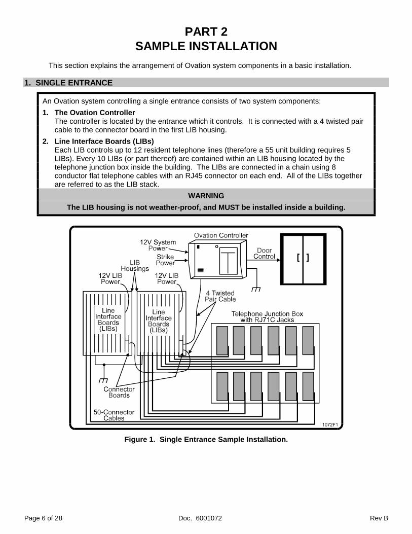
An Ovation system controlling a single entrance consists of two system components:
1. The Ovation ControllerThe controller is located by the entrance which it controls. It is connected with a 4 twisted paircable to the connector board in the first LIB housing.
2. Line Interface Boards (LIBs)Each LIB controls up to 12 resident telephone lines (therefore a 55 unit building requires 5LIBs). Every 10 LIBs (or part thereof) are contained within an LIB housing located by thetelephone junction box inside the building. The LIBs are connected in a chain using 8conductor flat telephone cables with an RJ45 connector on each end. All of the LIBs togetherare referred to as the LIB stack.
WARNING
The LIB housing is not weather-proof, and MUST be installed inside a building.
Figure 1. Single Entrance Sample Installation.
Rev B Doc. 6001072 Page 7 of 28
2. MULTIPLE ENTRANCES
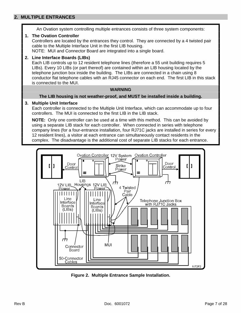
An Ovation system controlling multiple entrances consists of three system components:
1. The Ovation ControllerControllers are located by the entrances they control. They are connected by a 4 twisted paircable to the Multiple Interface Unit in the first LIB housing.NOTE: MUI and Connector Board are integrated into a single board.
2. Line Interface Boards (LIBs)Each LIB controls up to 12 resident telephone lines (therefore a 55 unit building requires 5LIBs). Every 10 LIBs (or part thereof) are contained within an LIB housing located by thetelephone junction box inside the building. The LIBs are connected in a chain using 8conductor flat telephone cables with an RJ45 connector on each end. The first LIB in this stackis connected to the MUI.
WARNING
The LIB housing is not weather-proof, and MUST be installed inside a building.
3. Multiple Unit InterfaceEach controller is connected to the Multiple Unit Interface, which can accommodate up to fourcontrollers. The MUI is connected to the first LIB in the LIB stack.
NOTE: Only one controller can be used at a time with this method. This can be avoided byusing a separate LIB stack for each controller. When connected in series with telephonecompany lines (for a four-entrance installation, four RJ71C jacks are installed in series for every12 resident lines), a visitor at each entrance can simultaneously contact residents in thecomplex. The disadvantage is the additional cost of separate LIB stacks for each entrance.
Figure 2. Multiple Entrance Sample Installation.
Page 8 of 28 Doc. 6001072 Rev B
PART 4PHONE LINE INSTALLATION
1. ARRANGING TELEPHONE INSTALLATION
Have the telephone company install RJ71C jacks in series, one for each 12 resident phone lines:
1. RJ71C blocks must be installed in an enclosed secured area not subject to weather.
2. Specify how and where you want them installed, and if possible be present during theirinstallation. Have them installed close to the LIBs to which they will be connected.
3. Use the form on the next page to clearly label lines by unit or apartment number, andgive a copy to the telephone company installer. This will help in installation and programming.
4. The telephone company requires the following information to install:
FCC registration number :DS8 USA-18617-OT-ERinger Equivalence Number (REN) :0.1BType of Connector Required :USOC RJ71C
2. INSTALLING RJ71C JACKS
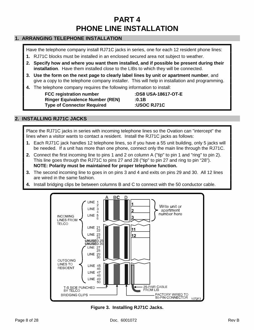
Place the RJ71C jacks in series with incoming telephone lines so the Ovation can "intercept" thelines when a visitor wants to contact a resident. Install the RJ71C jacks as follows:
1. Each RJ71C jack handles 12 telephone lines, so if you have a 55 unit building, only 5 jacks willbe needed. If a unit has more than one phone, connect only the main line through the RJ71C.
2. Connect the first incoming line to pins 1 and 2 on column A ("tip" to pin 1 and "ring" to pin 2).This line goes through the RJ71C to pins 27 and 28 ("tip" to pin 27 and ring to pin “28”).NOTE: Polarity must be maintained for proper telephone function.
3. The second incoming line to goes in on pins 3 and 4 and exits on pins 29 and 30. All 12 linesare wired in the same fashion.
4. Install bridging clips be between columns B and C to connect with the 50 conductor cable.
Figure 3. Installing RJ71C Jacks.
Rev B Doc. 6001072 Page 9 of 28
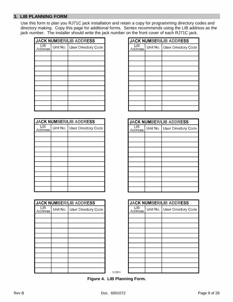
3. LIB PLANNING FORM
Use this form to plan you RJ71C jack installation and retain a copy for programming directory codes anddirectory making. Copy this page for additional forms. Sentex recommends using the LIB address as thejack number. The installer should write the jack number on the front cover of each RJ71C jack.
Figure 4. LIB Planning Form.
Page 10 of 28 Doc. 6001072 Rev B
PART 5PULLING CABLES
NOTE
Unshielded cable is acceptable for use in indoor, weather-proof installations. Shielded cableis required if wires will be run outdoors. Recommendations for both types of cable areprovided where needed.
1. SINGLE ENTRANCE
A. Ovation Controller Cabling
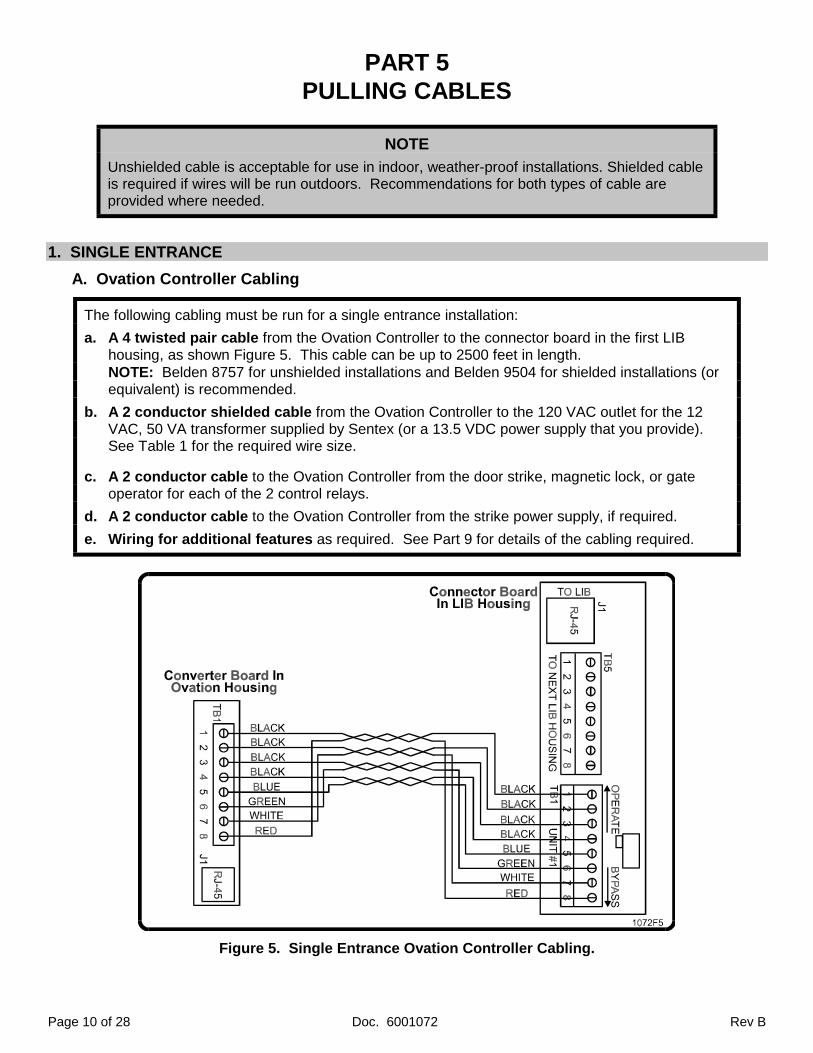
The following cabling must be run for a single entrance installation:
a. A 4 twisted pair cable from the Ovation Controller to the connector board in the first LIBhousing, as shown Figure 5. This cable can be up to 2500 feet in length.NOTE: Belden 8757 for unshielded installations and Belden 9504 for shielded installations (orequivalent) is recommended.
b. A 2 conductor shielded cable from the Ovation Controller to the 120 VAC outlet for the 12VAC, 50 VA transformer supplied by Sentex (or a 13.5 VDC power supply that you provide).See Table 1 for the required wire size.
c. A 2 conductor cable to the Ovation Controller from the door strike, magnetic lock, or gateoperator for each of the 2 control relays.
d. A 2 conductor cable to the Ovation Controller from the strike power supply, if required.
e. Wiring for additional features as required. See Part 9 for details of the cabling required.
Figure 5. Single Entrance Ovation Controller Cabling.
Rev B Doc. 6001072 Page 11 of 28
DC POWERWIRE SIZE
DISTANCE AC POWERWIRE SIZE
18 AWG 30' and under 18 AWG18 AWG 30'-75' 14 AWG14 AWG 75'-150' 12 AWG12 AWG 150'-250' 10 AWG10 AWG 250'-500' -----
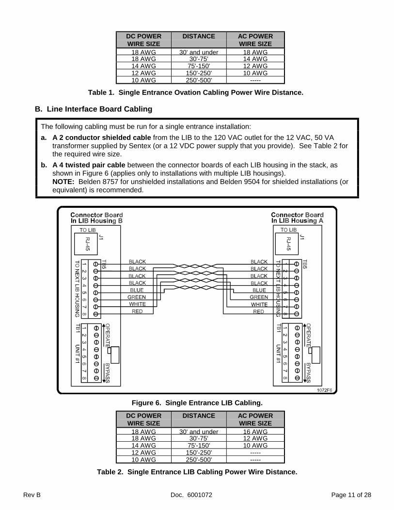
Table 1. Single Entrance Ovation Cabling Power Wire Distance.
B. Line Interface Board Cabling
The following cabling must be run for a single entrance installation:
a. A 2 conductor shielded cable from the LIB to the 120 VAC outlet for the 12 VAC, 50 VAtransformer supplied by Sentex (or a 12 VDC power supply that you provide). See Table 2 forthe required wire size.
b. A 4 twisted pair cable between the connector boards of each LIB housing in the stack, asshown in Figure 6 (applies only to installations with multiple LIB housings).NOTE: Belden 8757 for unshielded installations and Belden 9504 for shielded installations (orequivalent) is recommended.
Figure 6. Single Entrance LIB Cabling.
DC POWERWIRE SIZE
DISTANCE AC POWERWIRE SIZE
18 AWG 30' and under 16 AWG18 AWG 30'-75' 12 AWG14 AWG 75'-150' 10 AWG12 AWG 150'-250' -----10 AWG 250'-500' -----
Table 2. Single Entrance LIB Cabling Power Wire Distance.
Page 12 of 28 Doc. 6001072 Rev B
2. MULTIPLE ENTRANCES
A. Ovation Controller Cabling
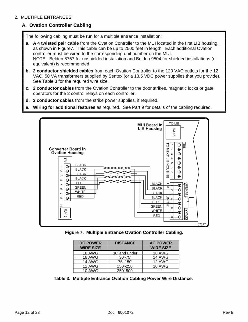
The following cabling must be run for a multiple entrance installation:
a. A 4 twisted pair cable from the Ovation Controller to the MUI located in the first LIB housing,as shown in Figure7. This cable can be up to 2500 feet in length. Each additional Ovationcontroller must be wired to the corresponding unit number on the MUI.NOTE: Belden 8757 for unshielded installation and Belden 9504 for shielded installations (orequivalent) is recommended.
b. 2 conductor shielded cables from each Ovation Controller to the 120 VAC outlets for the 12VAC, 50 VA transformers supplied by Sentex (or a 13.5 VDC power supplies that you provide).See Table 3 for the required wire size.
c. 2 conductor cables from the Ovation Controller to the door strikes, magnetic locks or gateoperators for the 2 control relays on each controller.
d. 2 conductor cables from the strike power supplies, if required.
e. Wiring for additional features as required. See Part 9 for details of the cabling required.
Figure 7. Multiple Entrance Ovation Controller Cabling.
DC POWERWIRE SIZE
DISTANCE AC POWERWIRE SIZE
18 AWG 30' and under 18 AWG18 AWG 30'-75' 14 AWG14 AWG 75'-150' 12 AWG12 AWG 150'-250' 10 AWG10 AWG 250'-500' -----
Table 3. Multiple Entrance Ovation Cabling Power Wire Distance.
Rev B Doc. 6001072 Page 13 of 28
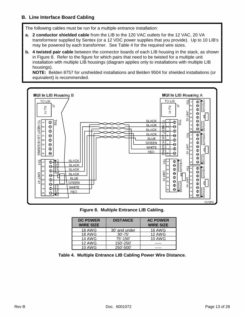
B. Line Interface Board Cabling
The following cables must be run for a multiple entrance installation:
a. 2 conductor shielded cable from the LIB to the 120 VAC outlets for the 12 VAC, 20 VAtransformesr supplied by Sentex (or a 12 VDC power supplies that you provide). Up to 10 LIB'smay be powered by each transformer. See Table 4 for the required wire sizes.
b. 4 twisted pair cable between the connector boards of each LIB housing in the stack, as shownin Figure 8. Refer to the figure for which pairs that need to be twisted for a multiple unitinstallation with multiple LIB housings (diagram applies only to installations with multiple LIBhousings).NOTE: Belden 8757 for unshielded installations and Belden 9504 for shielded installations (orequivalent) is recommended.
Figure 8. Multiple Entrance LIB Cabling.
DC POWERWIRE SIZE
DISTANCE AC POWERWIRE SIZE
18 AWG 30' and under 16 AWG18 AWG 30'-75' 12 AWG14 AWG 75'-150' 10 AWG12 AWG 150'-250' -----10 AWG 250'-500' -----
Table 4. Multiple Entrance LIB Cabling Power Wire Distance.
Page 14 of 28 Doc. 6001072 Rev B
PART 6MOUNTING THE CABINETS
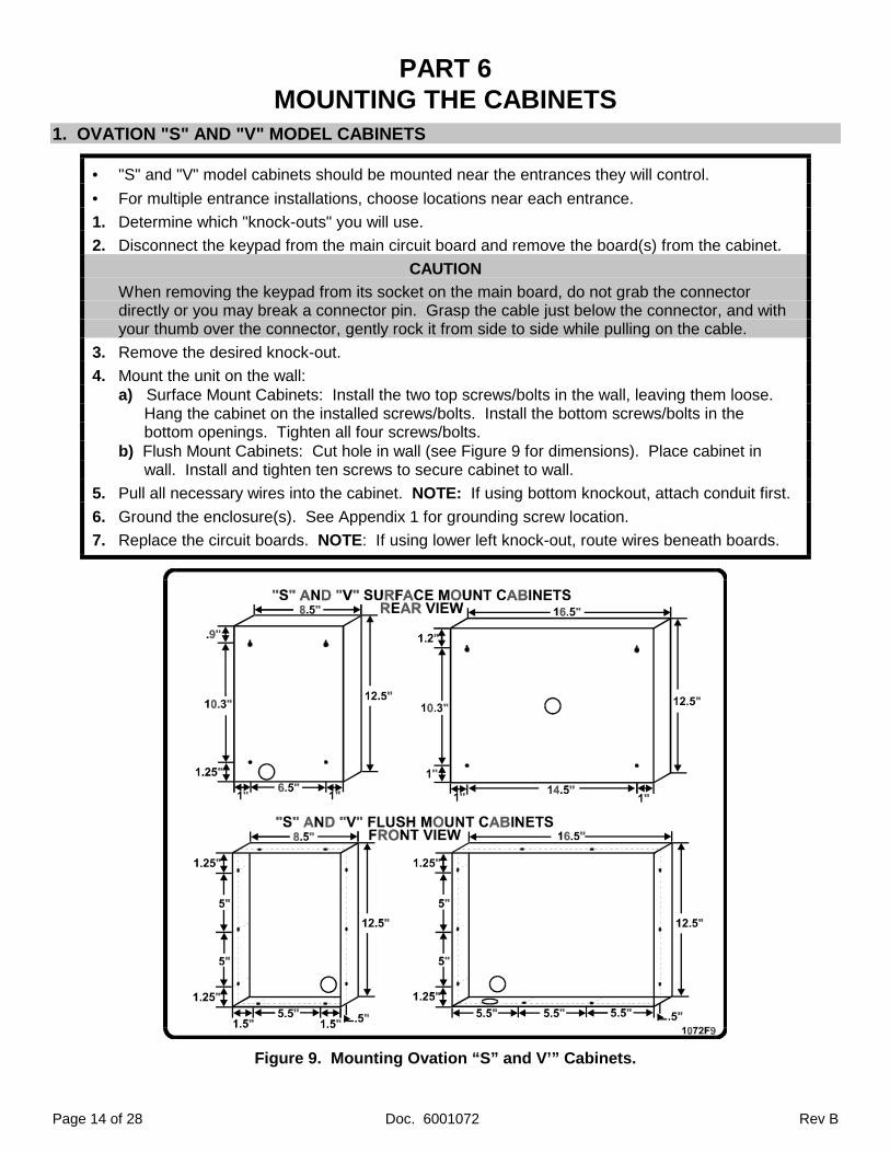
1. OVATION "S" AND "V" MODEL CABINETS
• "S" and "V" model cabinets should be mounted near the entrances they will control.
• For multiple entrance installations, choose locations near each entrance.
1. Determine which "knock-outs" you will use.
2. Disconnect the keypad from the main circuit board and remove the board(s) from the cabinet.
CAUTION
When removing the keypad from its socket on the main board, do not grab the connectordirectly or you may break a connector pin. Grasp the cable just below the connector, and withyour thumb over the connector, gently rock it from side to side while pulling on the cable.
3. Remove the desired knock-out.
4. Mount the unit on the wall:a) Surface Mount Cabinets: Install the two top screws/bolts in the wall, leaving them loose.
Hang the cabinet on the installed screws/bolts. Install the bottom screws/bolts in the bottom openings. Tighten all four screws/bolts.
b) Flush Mount Cabinets: Cut hole in wall (see Figure 9 for dimensions). Place cabinet in wall. Install and tighten ten screws to secure cabinet to wall.
5. Pull all necessary wires into the cabinet. NOTE: If using bottom knockout, attach conduit first.
6. Ground the enclosure(s). See Appendix 1 for grounding screw location.
7. Replace the circuit boards. NOTE: If using lower left knock-out, route wires beneath boards.
Figure 9. Mounting Ovation “S” and V’” Cabinets.
Rev B Doc. 6001072 Page 15 of 28
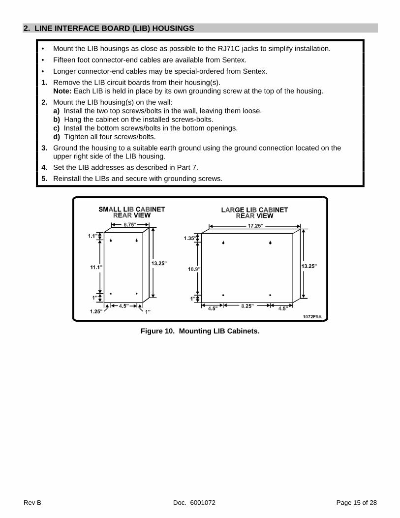
2. LINE INTERFACE BOARD (LIB) HOUSINGS
• Mount the LIB housings as close as possible to the RJ71C jacks to simplify installation.
• Fifteen foot connector-end cables are available from Sentex.
• Longer connector-end cables may be special-ordered from Sentex.
1. Remove the LIB circuit boards from their housing(s).Note: Each LIB is held in place by its own grounding screw at the top of the housing.
2. Mount the LIB housing(s) on the wall:a) Install the two top screws/bolts in the wall, leaving them loose.b) Hang the cabinet on the installed screws-bolts.c) Install the bottom screws/bolts in the bottom openings.d) Tighten all four screws/bolts.
3. Ground the housing to a suitable earth ground using the ground connection located on theupper right side of the LIB housing.
4. Set the LIB addresses as described in Part 7.
5. Reinstall the LIBs and secure with grounding screws.
Figure 10. Mounting LIB Cabinets.
Page 16 of 28 Doc. 6001072 Rev B
PART 7SETTING LIB ADDRESSES
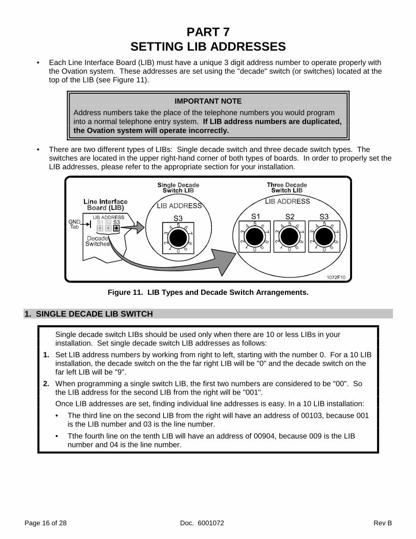
• Each Line Interface Board (LIB) must have a unique 3 digit address number to operate properly withthe Ovation system. These addresses are set using the "decade" switch (or switches) located at thetop of the LIB (see Figure 11).
IMPORTANT NOTE
Address numbers take the place of the telephone numbers you would programinto a normal telephone entry system. If LIB address numbers are duplicated,the Ovation system will operate incorrectly.
• There are two different types of LIBs: Single decade switch and three decade switch types. Theswitches are located in the upper right-hand corner of both types of boards. In order to properly set theLIB addresses, please refer to the appropriate section for your installation.
Figure 11. LIB Types and Decade Switch Arrangements.
1. SINGLE DECADE LIB SWITCH
Single decade switch LIBs should be used only when there are 10 or less LIBs in yourinstallation. Set single decade switch LIB addresses as follows:
1. Set LIB address numbers by working from right to left, starting with the number 0. For a 10 LIBinstallation, the decade switch on the the far right LIB will be "0" and the decade switch on thefar left LIB will be "9".
2. When programming a single switch LIB, the first two numbers are considered to be "00". Sothe LIB address for the second LIB from the right will be "001".
Once LIB addresses are set, finding individual line addresses is easy. In a 10 LIB installation:
• The third line on the second LIB from the right will have an address of 00103, because 001 is the LIB number and 03 is the line number.
• Tthe fourth line on the tenth LIB will have an address of 00904, because 009 is the LIB number and 04 is the line number.
Rev B Doc. 6001072 Page 17 of 28
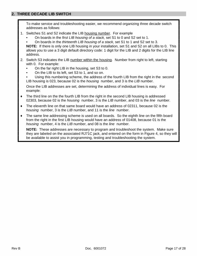
2. THREE DECADE LIB SWITCH
To make service and troubleshooting easier, we recommend organizing three decade switchaddresses as follows:
1. Switches S1 and S2 indicate the LIB housing number. For example• On boards in the first LIB housing of a stack, set S1 to 0 and S2 set to 1.• On boards in the thirteenth LIB housing of a stack, set S1 to 1 and S2 set to 3.NOTE: If there is only one LIB housing in your installation, set S1 and S2 on all LIBs to 0. Thisallows you to use a 3 digit default directory code: 1 digit for the LIB and 2 digits for the LIB lineaddress.
2. Switch S3 indicates the LIB number within the housing. Number from right to left, startingwith 0. For example:• On the far right LIB in the housing, set S3 to 0.• On the LIB to its left, set S3 to 1, and so on.• Using this numbering scheme, the address of the fourth LIB from the right in the secondLIB housing is 023, because 02 is the housing number, and 3 is the LIB number.
Once the LIB addresses are set, determining the address of individual lines is easy. Forexample:
♦ The third line on the the fourth LIB from the right in the second LIB housing is addressed02303, because 02 is the housing number, 3 is the LIB number, and 03 is the line number.
♦ The eleventh line on that same board would have an address of 02311, because 02 is thehousing number, 3 is the LIB number, and 11 is the line number.
♦ The same line addressing scheme is used on all boards. So the eighth line on the fifth boardfrom the right in the first LIB housing would have an address of 01408, because 01 is thehousing number, 4 is the LIB number, and 08 is the line number.
NOTE: These addresses are necessary to program and troubleshoot the system. Make surethey are labeled on the associated RJ71C jack, and entered on the form in Figure 4, so they willbe available to assist you in programming, testing and troubleshooting the system.
Page 18 of 28 Doc. 6001072 Rev B
PART 8MAKING BASIC CONNECTIONS
1. OVATION CONTROLLER CONNECTIONS
NOTE: Refer to Tables 1-4 for wire sizes and run distances for the following procedures.
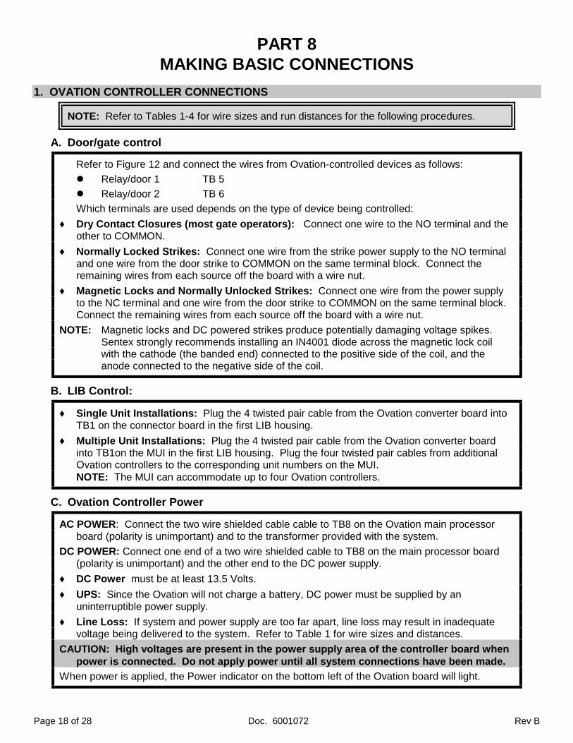
A. Door/gate control
Refer to Figure 12 and connect the wires from Ovation-controlled devices as follows:
! Relay/door 1 TB 5
! Relay/door 2 TB 6
Which terminals are used depends on the type of device being controlled:
♦ Dry Contact Closures (most gate operators): Connect one wire to the NO terminal and theother to COMMON.
♦ Normally Locked Strikes: Connect one wire from the strike power supply to the NO terminaland one wire from the door strike to COMMON on the same terminal block. Connect theremaining wires from each source off the board with a wire nut.
♦ Magnetic Locks and Normally Unlocked Strikes: Connect one wire from the power supplyto the NC terminal and one wire from the door strike to COMMON on the same terminal block.Connect the remaining wires from each source off the board with a wire nut.
NOTE: Magnetic locks and DC powered strikes produce potentially damaging voltage spikes. Sentex strongly recommends installing an IN4001 diode across the magnetic lock coil with the cathode (the banded end) connected to the positive side of the coil, and the anode connected to the negative side of the coil.
B. LIB Control:
♦ Single Unit Installations: Plug the 4 twisted pair cable from the Ovation converter board intoTB1 on the connector board in the first LIB housing.
♦ Multiple Unit Installations: Plug the 4 twisted pair cable from the Ovation converter boardinto TB1on the MUI in the first LIB housing. Plug the four twisted pair cables from additionalOvation controllers to the corresponding unit numbers on the MUI.NOTE: The MUI can accommodate up to four Ovation controllers.
C. Ovation Controller Power
AC POWER: Connect the two wire shielded cable cable to TB8 on the Ovation main processorboard (polarity is unimportant) and to the transformer provided with the system.
DC POWER: Connect one end of a two wire shielded cable to TB8 on the main processor board(polarity is unimportant) and the other end to the DC power supply.
♦ DC Power must be at least 13.5 Volts.
♦ UPS: Since the Ovation will not charge a battery, DC power must be supplied by anuninterruptible power supply.
♦ Line Loss: If system and power supply are too far apart, line loss may result in inadequatevoltage being delivered to the system. Refer to Table 1 for wire sizes and distances.
CAUTION: High voltages are present in the power supply area of the controller board whenpower is connected. Do not apply power until all system connections have been made.
When power is applied, the Power indicator on the bottom left of the Ovation board will light.
Rev B Doc. 6001072 Page 19 of 28
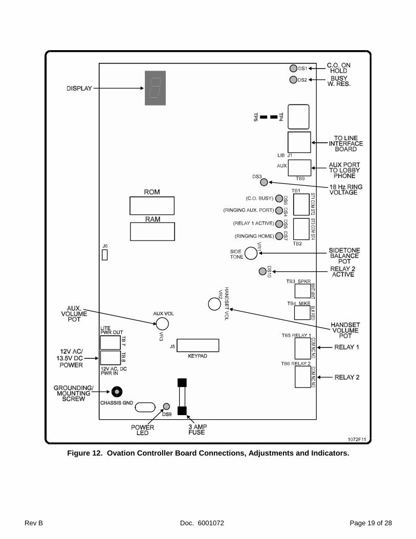
Figure 12. Ovation Controller Board Connections, Adjustments and Indicators.
Page 20 of 28 Doc. 6001072 Rev B
2. LIB CONNECTIONS
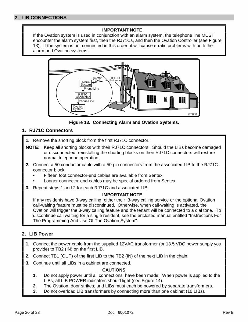
IMPORTANT NOTEIf the Ovation system is used in conjunction with an alarm system, the telephone line MUSTencounter the alarm system first, then the RJ71Cs, and then the Ovation Controller (see Figure13). If the system is not connected in this order, it will cause erratic problems with both thealarm and Ovation systems.
Figure 13. Connecting Alarm and Ovation Systems.
1. RJ71C Connectors
1. Remove the shorting block from the first RJ71C connector.
NOTE: Keep all shorting blocks with their RJ71C connectors. Should the LIBs become damaged or disconnected, reinstalling the shorting blocks on their RJ71C connectors will restore normal telephone operation.
2. Connect a 50 conductor cable with a 50 pin connectors from the associated LIB to the RJ71Cconnector block.• Fifteen foot connector-end cables are available from Sentex.• Longer connector-end cables may be special-ordered from Sentex.
3. Repeat steps 1 and 2 for each RJ71C and associated LIB.
IMPORTANT NOTEIf any residents have 3-way calling, either their 3-way calling service or the optional Ovationcall-waiting feature must be discontinued. Otherwise, when call-waiting is activated, theOvation will trigger the 3-way calling feature and the tenant will be connected to a dial tone. Todiscontinue call waiting for a single resident, see the enclosed manual entitled "Instructions ForThe Programming And Use Of The Ovation System".
2. LIB Power
1. Connect the power cable from the supplied 12VAC transformer (or 13.5 VDC power supply youprovide) to TB2 (IN) on the first LIB.
2. Connect TB1 (OUT) of the first LIB to the TB2 (IN) of the next LIB in the chain.
3. Continue until all LIBs in a cabinet are connected.
CAUTIONS1. Do not apply power until all connections have been made. When power is applied to the
LIBs, all LIB POWER indicators should light (see Figure 14).2. The Ovation, door strikes, and LIBs must each be powered by separate transformers.3. Do not overload LIB transformers by connecting more than one cabinet (10 LIBs).
Rev B Doc. 6001072 Page 21 of 28
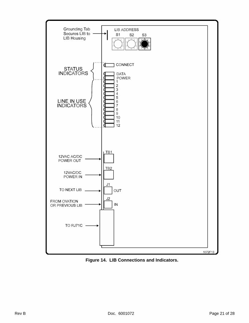
Figure 14. LIB Connections and Indicators.
Page 22 of 28 Doc. 6001072 Rev B
3. LIB Control
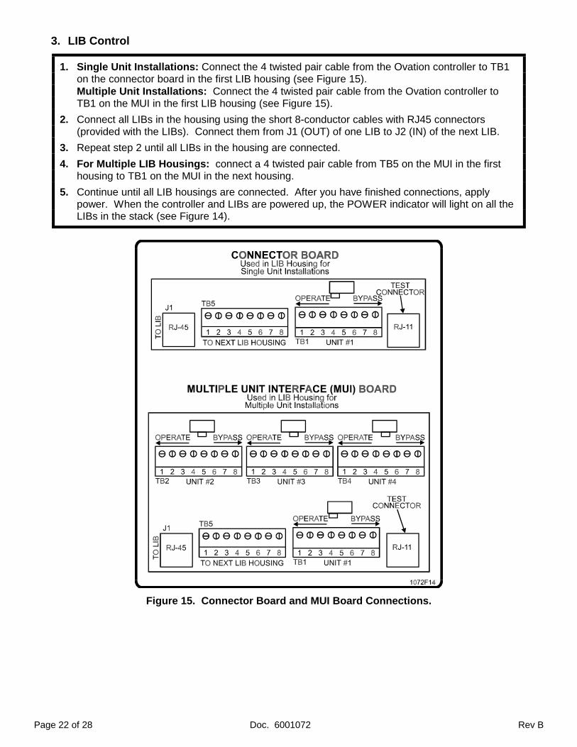
1. Single Unit Installations: Connect the 4 twisted pair cable from the Ovation controller to TB1on the connector board in the first LIB housing (see Figure 15).Multiple Unit Installations: Connect the 4 twisted pair cable from the Ovation controller toTB1 on the MUI in the first LIB housing (see Figure 15).
2. Connect all LIBs in the housing using the short 8-conductor cables with RJ45 connectors(provided with the LIBs). Connect them from J1 (OUT) of one LIB to J2 (IN) of the next LIB.
3. Repeat step 2 until all LIBs in the housing are connected.
4. For Multiple LIB Housings: connect a 4 twisted pair cable from TB5 on the MUI in the firsthousing to TB1 on the MUI in the next housing.
5. Continue until all LIB housings are connected. After you have finished connections, applypower. When the controller and LIBs are powered up, the POWER indicator will light on all theLIBs in the stack (see Figure 14).
Figure 15. Connector Board and MUI Board Connections.
Rev B Doc. 6001072 Page 23 of 28
PART 9INSTALLING ADDITIONAL FEATURES
The following features are connected in the same fashion for the "S" or "V" models, regardless ofsingle or multiple entrance installations.
1. POSTAL LOCK
♦ The Post Office requires installation of their own lock where mail-boxes are inside a controlledarea.
♦ Your customer must arrange with the postal carrier to have a postal lock installed before thepostal lock kit can be installed.
♦ A kit for wiring the postal lock switch is provided with each system. Specific directions forconnecting these parts to "ST1" and "COM" on TB1 are included in the postal lock kit.
♦ Once installed, when the postal carrier turns the key in the lock, the system activates relay 1 forthe programmed period of time.
2. AUX OPEN/REQUEST FOR ACCESS
♦ Any device such as a Knox box or exit button providing a contact closure can be wired to theOvation to provide access.
! Devices wired to ST1 and COM on TB1 activate Relay 1.
! Devices wired to ST3 and COM on TB2 activate Relay 2 (if Relay 2 is set as a control).
♦ Use shielded cable such as Belden 8771, with the shield connected to the Controller boardground screw. When contact closure occurs, the system activates the associated relay for theprogrammed period of time.
3. DOOR POSITION SENSING
The Ovation can monitor the position of two doors and act based on their status. If a door ispried open, or is held open for more than a minute after its relay deactivates, the system cancall a telephone number and report its condition, and/or close a relay to activate a device suchas a camera, siren, etc. To use this feature:
1. Install a normally closed switch in the door frame so it is depressed when the door is closed.
2. Wire the normally closed (NC) and common (COM) terminals of the switch to:! ST2 and COM on TB1 (for door 1).! ST4 and COM on TB2 (for door 2).
3. Use shielded cable such as Belden 8771 and ground the shield to the Ovation controller boardground screw shown in Figure 12.
Page 24 of 28 Doc. 6001072 Rev B
PART 10TESTING AND ADJUSTING THE UNIT
To ensure proper operation, the following procedures must be performed, and may also be helpful introubleshooting the system after installation. For more detail, refer to the "Programming and UseInstructions for the Ovation system" manual.
1. VERIFYING CODE CAPABILITIES
1. Verify that all LIBs are set properly and there is no duplication of 3-digit LIB addresses.
2. To ensure the entry codes feature works properly, on the controller keypad, enter theprogramming mode board by entering three asterisks ("∗∗∗ ") followed by the six digit userdefined password (factory setting is 000000).
3. Enter programming step 08 and set the relay activation time for relay 1 followed by the "#" sign.The relay activation time can be entered any two-digit number from 01 and 99 seconds.
4. Enter programming step 16 and enter a four digit entry code followed by the "#" sign.
5. Enter the entry code programmed in step 4 on the front entrance Ovation, verify access isgranted for the correct length of time, and verify that the Ovation emitted 10 beeps.
2. ADJUSTING SIDETONE BALANCE
1. Place a volt meter on TP4 (+) and TP5 (-) of the Ovation controller board (see Figure 12).
2. Enter the programming mode by entering three asterisks ("∗∗∗ ") followed by the six digit userdefined password (factory setting is 000000).
3. Enter programming step "69" followed by the three-digit LIB number, the two-digit line numberof the line you wish to use for this test, and the "#" key. When you hear the tone, adjust the"SIDETONE BALANCE" pot on the Ovation controller board to minimize the DC voltagebetween these two points.
3. VERIFYING TELEPHONE AND DOOR/GATE CONNECTIONS
1. Incoming Line Test
♦ To verify system connections, each resident’s phone and outgoing line must be tested.You will need a standard tone dial telephone and cord with RJ11 connectors on both ends.
1. Plug your test telephone into the test connector on any MUI, lift the handset and dial "∗∗∗ 5". Abeep will indicate you are in a limited programming mode (you may only do the areas describedon this page and the next). See Figure 14 for location of the MUI test connector.
2. After you hear the beep, enter "23" followed by the 3 digit LIB address and the 2 digit lineaddress of the unit you wish to contact, followed by a "# ".
3. Hang up the handset. The test phone and resident's phone will ring simultaneously. Do notanswer the test set until ringing stops (the resident has answered) or you decide no one isgoing to answer (ringing stops when you pick up the handset). If the resident answers, pick upyour handset and confirm their identity.
4. After talking to the resident (or picking up the handset to stop ringing), hang the handset up
5. Repeat for each resident starting at Step 1. If no one answers thehone, note this on the "LIBplanning form" in Figure 4 and ensure these lines operate properly when a resident is in.
Rev B Doc. 6001072 Page 25 of 28
2. Outgoing Line Test
1. Plug your test telephone into the test connector on any MUI, lift the handset and dial "∗∗∗ 5". Abeep will indicate you are in a limited programming mode (you may only do the areas describedon this and the last page). See Figure 15 for location of the MUI test connector.
2. After you hear the beep, enter "24" followed by the 3 digit LIB address and the 2 digit lineaddress of the unit you wish to contact, followed by a "# ". This cuts into resident’s phone line.If the resident is on the phone, you will be on the line with them and the incoming telephoneline. Verify the connection is correct. If the resident is not on the phone, you will hear their dialtone. Note this number on the "LIB planning form" in Figure 4 and ensure these lines operateproperly when a resident is in.
3. Repeat Steps 1 and 2 for each line.
♦ Verify that each resident's telephone line is functioning properly within the building. In caseswhere the resident has no telephone service, no dial tone should be heard.
3. Door/Gate Connections
1. To test door/gate connections, call a resident from the Ovation. When the resident answers,identify yourself and ask them to press "9" on their telephone.
2. Verify the device attached to relay 1 activates for the specified period of time and that 10 beepsare emitted from the front panel speaker.
3. If there is a second door or gate connected to relay 2, call a resident from the keypad located atthe front entrance to the building/complex. When the resident answers their telephone, identifywho you are and ask them to press a "5" on their telephone keypad.
4. Verify that the device attached to relay 2 activates for the specified period of time and that 10beeps are emitted from the front panel speaker.
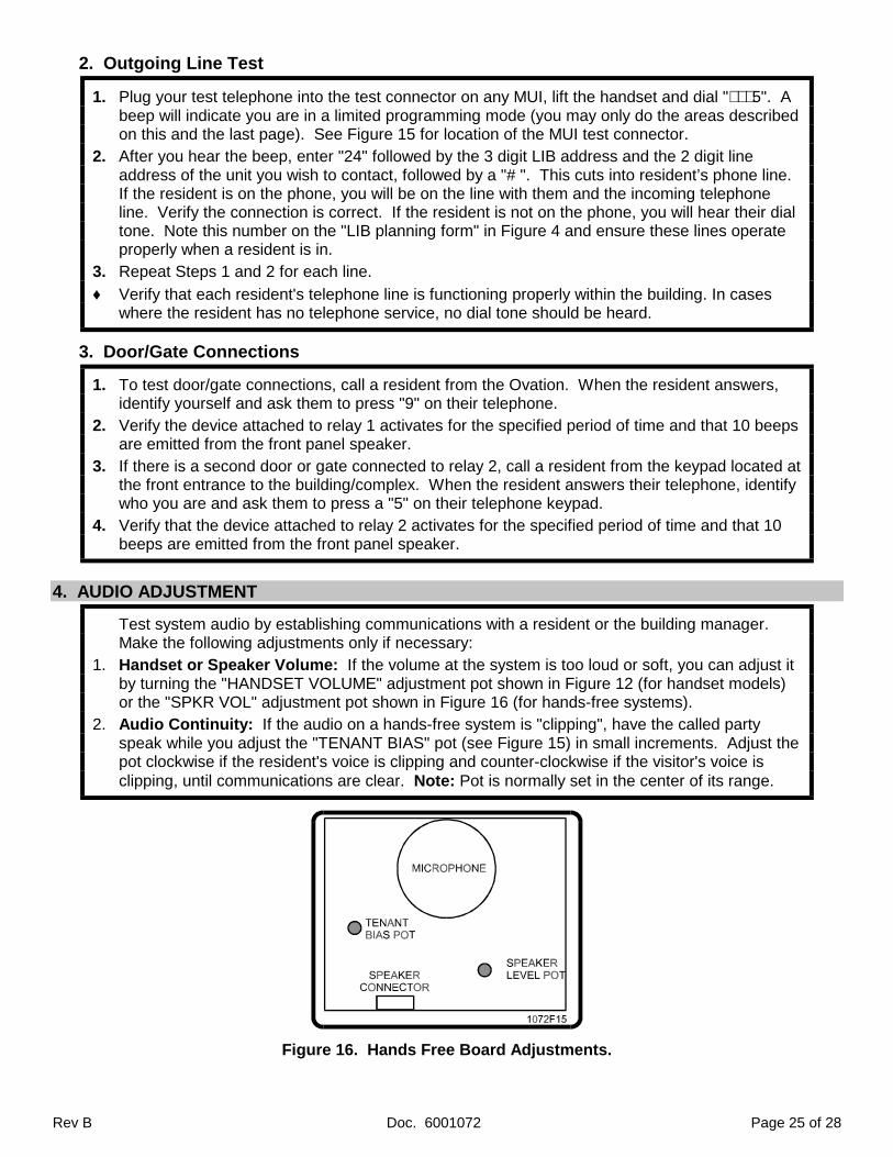
4. AUDIO ADJUSTMENT
Test system audio by establishing communications with a resident or the building manager.Make the following adjustments only if necessary:
1. Handset or Speaker Volume: If the volume at the system is too loud or soft, you can adjust itby turning the "HANDSET VOLUME" adjustment pot shown in Figure 12 (for handset models)or the "SPKR VOL" adjustment pot shown in Figure 16 (for hands-free systems).
2. Audio Continuity: If the audio on a hands-free system is "clipping", have the called partyspeak while you adjust the "TENANT BIAS" pot (see Figure 15) in small increments. Adjust thepot clockwise if the resident's voice is clipping and counter-clockwise if the visitor's voice isclipping, until communications are clear. Note: Pot is normally set in the center of its range.
Figure 16. Hands Free Board Adjustments.
Page 26 of 28 Doc. 6001072 Rev B
PART 11GLOSSARY OF DIAGNOSTIC INDICATORS
1. OVATION CONTROLLER BOARD
The Ovation controller board has a number of indicator lights to help you determine the statusof the board and whether it is installed correctly. See Figure12 for indicator locations.
C.O. ON HOLD (DS1): This indicator lights when the Ovation controller has a resident's TELCOline on hold during call waiting.
BUSY WITH RES. (DS2): This indicator lights when the resident is in contact with the visitorentrance.
18Hz RING VOLTAGE (DS3): This indicator flashes when the controller rings any telephone.
RINGING AUX PORT (DS4): This indicator flashes when the controller rings the Lobby Telephone(Aux telephone port).
RELAY 1 ACTIVE (DS5): This indicator remains lit while Relay 1 is activated for the programmedtime.
C.O. BUSY (DS6): This indicator lights when the controller calls an outside telephone number(i.e., not a resident).
RINGING HOME (DS7): This indicator flashes when the controller is ringing a resident.
POWER ON (DS9): This indicator lights if power is connected to the system.
RELAY 2 ACTIVE (DS10): This indicator remains lit while Relay 2 is activated for the programmedtime
2. LINE INTERFACE BOARD (LIB)
Line Interface Boards also have indicators. See Figure 14 for indicator locations.
CONNECT: This indicator lights while the LIB connects the controller to a resident's line, or duringtesting with program steps 24 and 25. While a resident's phone line is connected one of thetwelve line in use indicators will also light.
DATA: This indicator lights only when "line selection tones" are being received from the controller.
POWER: This indicator lights whenever power is connected to the LIB.
1 thru 12: These indicators light when a line is in use. Only one line indicator on the LIB stackshould be lit at one time.
Rev B Doc. 6001072 Page 27 of 28
FCC REQUIREMENTS
1. INSTALLATION
This equipment complies with part 68 of the FCC rules on the front inside of the cabinet is a label which containsthe following information:
1. The FCC registration number for the system, which is DS8 USA-18617-OT-E.
2. The ringer equivalence number (REN) which is 0.1B.
This system connects to the telephone lines by means of a standard jack called the USOC RJ71C. This jackwould be installed by the telephone company.
The REN is used to determine the quantity of devices which may be connected to the telephone line. ExcessiveREN’s on the telephone line may result in devices not ringing in response to an incoming call. The sum of the REN’sshould not exceed five (5.0). To be certain of the number of devices that may be connected to the line, as determined bythe total REN’s, contact the telephone company to determine the maximum REN’s for the calling area.
2. TYPE OF SERVICE
Your Sentex Ovation system is designed to be used on a standard device telephone lines. The system should notbe connected to coin service or party lines. If you have any questions about your telephone line, such as how many piecesof equipment may be connected to it, the telephone company will provide this information upon request.
3. TELEPHONE COMPANY PROCEDURES
The goal of the telephone company is to provide you with the best service it can. In order to do this, it mayoccasionally be necessary for them to make changes in their equipment, operations, or procedures. If these changesmight affect your service the operation of your equipment, the telephone company will give notice, in writing, to allow you tomake changes necessary to maintain uninterrupted service.
4. IF PROBLEMS ARISE
If your telephone equipment is not operating properly, you should immediately remove it from the telephone lines,as it may cause harm to the network. If the telephone company notes a problem, they may temporarily discontinueservice. When practical they will notify you in advance of the discontinuation. If advance notice is not feasible, you will benotified as soon as possible. When you are notified, you will be given the opportunity to correct the problem and informedof your right to file complaint with the FCC.
In the event any repairs are ever needed on your system, they should be performed only by an authorizedrepresentative of Sentex Systems, Inc.
5. RADIO FREQUENCY
This equipment has been tested and found to comply with the limits for a Class B digital device, pursuant to part15 of the FCC Rules. These limits are designed to provide reasonable protection against harmful interference when theequipment is operates in a residential environment. This equipment generates, uses, and can radiate radio frequencyenergy and, if not installed and used in accordance with the instruction manual, may cause harmful interference to radiocommunications. However, there is no guarantee that interference will not occur in a particular installation. If thisequipment does cause harmful interference to radio or television reception, which can be determined by turning theequipment off and on, the user is encouraged to try to correct the interference by one or more of the following measures:
- Reorient or relocate the receiving antenna.
- Increase the separation between the equipment and receiver.
- Connect the equipment into an outlet on a circuit different from that to which the receiver is connected.
- Consult the dealer or an experienced radio/TV technician for help.
If necessary, the user should consult the dealer or an experienced radio/television technician for additionalsuggestions. The user may find the following booklet prepared by the FCC helpful: “How to Identify and Resolve RadioTelevision Interference Problems”. This booklet is available from the United States Government Printing Office,Washington, DC, 20402, Stock No. 004-000-00345-4.
Page 28 of 28 Doc. 6001072 Rev B
DOC REQUIREMENTS
NOTICE: The Canadian Department of Communications label identifies certified equipment. Thiscertification means that the equipment meets certain telecommunications network protective, operational, andsafety requirements. The Department does not guarantee the equipment will operate to the user’ssatisfaction.
Before installing this equipment, users should ensure that it is permissible to be connected to thefacilities of the local telecommunications company. The equipment must also be installed using an acceptablemethod of connection. In some cases, the company’s inside wiring associated with a single line individualservice may be extended by means of a certified connector assembly (telephone extension cord). Thecustomer should be aware that compliance with the above conditions may not prevent degradation of servicein some situations.
Repairs to certified equipment should be made by an authorized Canadian maintenance facilitydesignated by the supplier. Any repairs or alterations made by the user to this equipment, or equipmentmalfunctions, may give the telecommunications company cause to request the user to disconnect theequipment.
Users should ensure for their own protection that the electrical ground connections of the power utility,telephone lines and internal metallic water pipe system, if present, are connected together. This precautionmay be particularly important in rural areas.
Caution: Users should not attempt to make such connections themselves, but should contact theappropriate electric inspection authority, or electrician, as appropriate.
The Load Number (LN) assigned to each terminal device denotes the percentage of the total load to beconnected to a telephone loop which is used by the device, to prevent overloading. The termination on a loopmay consist of any combination of devices subject only to the requirement that the total of the Load Numbersof all the devices does not exceed 100. The Load Number for the Ovation system is 4.