Embed Size (px)
Citation preview

key override module
In A Single Motion, We’ll Change The Way You Think About Security
Installation InstructionsConverting The LKM7000 to The LKM7003
Read Instructions thoroughly prior to installation
lkm7001lkm7001
18 - Base Plate Cover19 - Cover Screws (4 total)20 - Label21 - Exit Handle22 - Flag Mtg Stud23 - Torsion Spring24 - Casting Mtg. Screw25 - Yoke Bearing26 - Yoke Bias Spring27 - Night Latch Mtg. Bracket28 - Spring29 - Bolt Latch30 - Wiring Harness31 - Bracket Mtg. Screw32 - Switch Actuator Assembly33 - Internal Access Control34 - Spring35 - Bolt Actuator Slide36 - Relock Mtg. Stud37 - Relock Lever38 - Relock Spring39 - Bracket Mtg. Screw40 - Plate Mtg. Screw41 - Slide Mtg. Plate42 - Lock Slide Assembly43 - Base Plate44 - Relock Lever45 - Slide Cover Plate46 - Spring47 - Trigger48 - Switch Mtg. Bracket49 - Switch Insulator50 - Switch Mtg. Screw51 - Block Pivot Pin52 - Trigger Block53 - Bolt Assembly54 - Night Latch Slide55 - Bracket Mtg. Screw56 - Actuator Yoke57 - Yoke Pivot Bearing58 - Top Casting59 - Indicator Tape60 - Lockout Indicator Flag61 - Lock Cap
PLEASE NOTE - Some parts are not available.
1 - Mounting Screws2 - Access Control Cover3 - Circuit Card Assembly4 - Electronic Shield Plate5 - Solenoid Blk Mtg Screw 6 - Access Control Assembly7 - Actuator Return Spring8 - Bypass Actuator9 - Cylinder Cam Hub10 - Lock Lever Return Spring11 - Access Control Lock Lever12 - Access Control Casting13 - Serial Number Label14 - Light Lens Ring15 - Light Pipe16 - Cylinder Mounting Plate17 - LED Lens
Note: Rim Cylinder is not included
Base Plate & Key Override Module Exploded View ListingKey Override Module Exploded View Listing
Base Plate Exploded View Listing

1
a. key override moduleB. key override module cover plate shipped installed - #8 Hex Head (2)
c. key cylinder plated. Green indicator Button - light indicator assemblye. WHite collar - light indicator assemblyf. liGHt tuBe - light indicator assemblyG. key override module ScreWS - 1-1/4” Self tapping Screws (2)
H. mountinG platei. inStallation templateS
lkm7001 Main Components
G
Ha
c
B
d ef
i

2
poWer drill (we recommend one with a level attached)pHillipS ScreWdriverSmall flat ScreWdriver1/16”, 3/16”, 3/32” and 5/64” allen WrencHeS1 - 1/4” Hole SaW or Wood cuttinG Bit1/8”, 3/16”, 3/8”, 5/16” drill BitScenter puncHHammerfiletapeWire cutterS & StripperSHex WrencHGoGGleS
toolS needed For Wooden or Metal Door Installation
WarninG!Must Read Before Installation
IT IS IMpeRATIve ThAT The DooR ReMAIn open DuRIng InSTAllATIon oF The lKM7001 AnD/oR ChAngIng The loCK CoMBInATIon. If the door closes while the back cover is removed, the relockers will trigger thus causing a lock out.
Note: Be sure to wear eye protection when drilling!

3
Step 1A - Removing Base Plate Back (Cover Screws - 4 total.)
Step 1 - removinG tHe lkm7000 inSide BaSe plate mounted lkm7000 from tHe doorStep 1A - With a 3/32” hex wrench, remove the 4 (A) Inside Base Plate cover screws.
Step 1B - Depress the exit handle and inset a pocket screwdriver under the cover directly behind the handle and gently pry up in order to release the back cover. Tilt the cover and slide it out of the exit handle.
CAUTION: DO NOT LET THE DOOR CLOSE WHILE THE BACK COVER IS OFF. IF THIS HAPPENS A LOCK OUT WILL OCCUR!
Step 1C - Remove the combination lock that is in the existing LKM7000 and disconnect the power from the access control card reader.
Step 1D - Using a 3/16” hex wrench, remove the (4) hex head machine screws from the Base Plate. Remove the (4) thread forming screws using a Phillips screwdriver and remove the Inside Base Plate from the door.
Step 1e - Use a Phillips screwdriver to remove the (2) lower screws and finishing washers and then remove the Front Plate from the door.
pleASe noTe: By adding the Key override Module, you are converting the lKM7000 to a lKM7003. If needed, go to www.lockmasters.com for lKM7003 instructions.
key override module Installation
Step 1B - Releasing the Base Plate Cover and removing
a
aa
a
Step 1C - Removing the combination lock
Step 1D - Removing the (4) screws to remove the Inside Base Plate.
Step 1e - Removing the (2) lower screws that hold the Front Plate to the door.

4
key override module Installation
Step 2 - attacHinG tHe lkm7001 inStallation templateS
Step 2A - Once the LKM7000 has been removed, position the correct template to the front and to the back side of the door. Align the existing drilled holes to the correspond-ing holes on the template. Tape to door to secure.
Please Note: Installation templates are provided for both right and left hand doors. Step 2A - Align existing drilled holes with
corresponding holes on the LKM7001 template.
Step 3 - preppinG inSide of tHe doorStep 3A - Use a center punch to mark the rim cylinder hole (F), the green light indicator hole (H), the 2 thread forming screw holes (G) and the optional wire entry hole (J), ONLY if the door is equipped with an internal raceway.
Step 3B - Once the holes are center punched, move the template above the for easy reference. Mark all holes to be drilled with the correct diameter. Use an 1/8” drill bit to pilot drill the holes.
Please Note: Label each hole on the door with the corresponding letter on the template to ensure the correct drill bit size is used. Hole diameters and depths are noted on the templates.
Step 3A - Center punching Inside Base Plate.
Step 3B - Mark all holes to be drilled.
5
key override module Installation
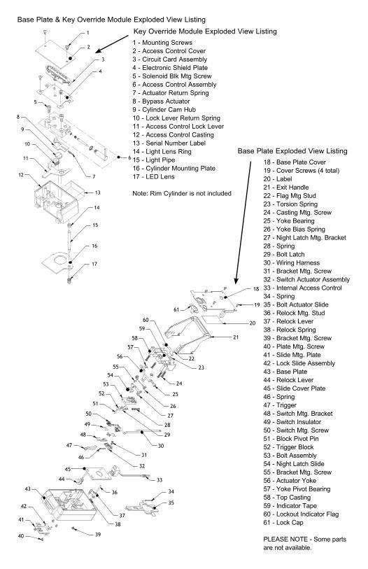
Step 4 - preppinG outSide of tHe door
Step 4A - Center punch and mark the rim cylinder hole (F) and the green light indicator hole (H).
Step 4A - Use a center punch to mark the rim cylinder hole (F), and the green light indicator hole (H).
Step 4B - Once the holes are center punched, tape the template above the lock for easy reference and mark all the holes to be drilled. Use an 1/8” drill bit to pilot drill the holes.
Please Note: Label each hole on the door with the corresponding letter on the template to ensure the correct drill bit size is used. Hole diameters and depths are noted on the templates.
Step 4B - Mark all holes to be drilled.

6
Step 5 - drill tHe HoleS on tHe inSide of tHe doorNOTICE - Due to alignment issues, you should NEVER drill a through hole in a hollow door. To ensure a level through hole, you should drill through one side of the door then drill through the other side of the door. This will prevent splintering in solid wood doors. Make sure to keep the drill as level as possible.
Step 5A - Attach a 1-1/4” hole saw or wood cutting bit and drill the Rim Cylinder Hole (F).
Step 5B - Attach a 3/16” drill bit and drill the 2 thread forming screw holes. (On wood doors, drill to a depth of 1”.) Use tape on the drill bit to mark this depth.
Step 5C - Attach a 3/8” drill bit and finish drill-ing the Green Light Indicator Hole (H).
Step 5D - opTIonAl WIRe enTRY holeThe wire entry hole is drilled when a door has been prepped with an internal raceway for routing wire for the access control and/or bolt monitor switches. An external hole is provided in the key override casting for wiring which is routed externally on the secure side of the door through shielded cable or conduit.
key override module Installation
Step 5A - Drilling the Rim Cylinder Hole (F) on the inside of the door
Step 5B - Drilling the 2 thread forming screw holes.
exTeRnAlenTRY hole Step 5C - Drilling Green Light Indicator
Hole (H)

7
key override module Installation
Step 8 - aSSemBle tHe Green liGHt indicator to tHe key cylinder plate
Step 7 - Deburring all drilled holes.
Step 7A - Use a deburring stone or round file to eliminate any burrs, metal shavings or splinters on all new drilled holes prior to lock installation.
Step 7 - preppinG drilled HoleS prior to inStallation
NOTE - Depending on the door handing, The Green Light Indicator must always be assembled so the light is located ON TOP of the Key Cylinder Plate.
Step 8A - Slide the green lens into the key cylinder plate.
Step 8B - Slide the white collar over the back side of the green lens.
Step 8C - Insert the small end of the acrylic light tube into the backside of the green lens until it snaps into position. Step 8B - Inserting the white collar.
Step 8C - Securing Light Tube into place
Step 8A - Inserting the green lens into the cylinder plate.
A B
Assembled Green Indicator Light Tube
Step 6 - drill tHe HoleS on tHe outSide of tHe doorStep 6A - Attach an 1-1/4” hole saw or wood cutting bit and finish drilling the Rim Cylinder Hole (F).
Step 6B - Attach a 3/8” drill bit and finish drilling the Green Light Indicator Hole (H).
Step 6A - Drilling the Rim Cylinder Hole (F)
Step 6B - Drilling the Green Light Indicator Hole (H).

8
key override module Installation
Step 9 - preppinG tHe front plate for mountinGStep 9A - Using the 5/32” hex wrench, remove the (4) back cover screws.
Step 9B - Carefully lift & remove the back cover making sure not to shift any internal parts.
Please refer to the illustration if the gears happen to shift.
Step 9A - Removing the (4) back cover screws. (Shown with standoff kit)
Step 9B - Carefully removing back cover.
TIMIng MARKS
Lever Handle Gear
Spindle Gear
Spindle & Lever Handle Gear Alignment
Attention: Make sure the timing marks on the gears are in alignment.

9
key override module Installation
Step 10 - attacHinG tHe rim cylinder WitHout mountinG plateStep 10A - Insert and attach the appropri-ate Rim Cylinder through the 1-1/4” hole that was prepped earlier. Check for smooth oper-ation. Lockmasters recommends using an interchangeable core for ease of re-keying.
Step 10B - Mark and trim the cylinder tail piece so that it extends 1/8” to 3/16” beyond the surface of the door or mounting plate.
Step 9C - Remove 1 of the 2 plastic Filler Plugs where the Key Cylinder Plate goes on the Front Plate. Re-attach the back cover onto the Front Plate. Make sure the remaining plastic Filler Plug stays intact.
Please Note: The slotted side of the Filler Plug should be facing you.
By removing this Filler Plug, you allow the Front Plate to lay flush on the door. Step 9C - Removing 1 of 2 plastic Filler
Plugs.
Step 10A - Insert Rim Cylinder.
optional - attacHinG tHe rim cylinder uSinG lockmaSterS’ mountinG plate
Step 10B - Cylinder tail piece marked and trimmed.
Lockmasters offers an optional mount-ing plate (Part number: LKM7003MP) with a key cylinder reinforcement sleeve. We recommend using this on all hollow doors to prevent the door from collapsing while tightening the Rim Cylinder mounting screws. Using this plate will increase the door thick-ness by 1/8” which may affect the dial spindle and tubes used to install the combination lock. It’s a good idea to order extra parts for the combination lock when using this plate. Make sure this plate is in place before you cut the tail piece of the Rim Cylinder.
optional Step 10A - First, determine the handing of the mounting plate. Seat the smaller end of the cylinder reinforcement tube into the plate and use a rubber mallet to seat it into place.
optional Step 10C - Determine handling of the mounting plate.
Seat tube into place using a rubber mallet.

key override module Installation
10
optional Step 10B - Use double stick tape to hold the plate into position until the tail piece has been cut to the correct length.
optional Step 10C - Install Rim Cylinder in the Rim Cylinder hole (F). Keep in mind, if the optional mounting plate is used you will need to use the cylinder back plate supplied with the mounting plate kit.
optional Step 10D - Mark and trim the cylin-der tail piece so that it extends 1/8” to 3/16” beyond the surface of the door or mounting plate.
optional Step 10D - Apply double stick tape to mounting plate.
Mounting plate Installed
optional Step 10F - Cylinder tail piece marked and trimmed.
Lockmasters’ Standoff Kit
noTe: If you are using a standoff kit install this now.
Step 11A - Insert the Front Plate through the existing holes in the door and hold into position.
Step 11 - re-attacH tHe front plate to tHe door
Step 11A - Inserting Front Plate through existing holes.

11
key override module Installation
Step 11B - Inserting screws and finish washers in the lower mounting holes.
Apply thread locker to (2) Phillips head screws.
Step 12 - removinG tHe internal acceSS control BlockThe Key Override Module now contains the access control block. Therefore, removal of the internal access control block provided with the original LKM7000 will need to be removed to avoid a potential lockout.
Step 12A - Use a 5/32” hex wrench to remove the (2) screws securing the Internal Access Control Block. These are located on the back side of the LKM7000 Inside Base Plate. Once the screws are removed you can now com-pletely extract the Internal Access Control Block and wiring from the Inside Base Plate.
pleASe noTe: By adding the Key override Module, you are converting the lKM7000 to a lKM7003. If needed, go to www.lockmasters.com for lKM7003 instructions.
Step 12A - Remove (2) screws securing internal Access Control Block.
Step 11B - Permanently secure using the (2) Phillips head screws and finish washers in the lower mounting holes. Make sure to use thread locker on these screws to prevent them from loosening overtime.
note: If a standoff kit is installed use the shorter phillips head screws provided in the standoff kit.

12
key override module Installation
KeY oveRRIDe MoDule TAIlpIeCe
loCKIng hooKS
Step 13B - Interlocking the Key Override Module with the LKM7000 Base Plate
Step 13 - preppinG tHe key overide module.Step 13A - Use a 3/32” hex wrench to remove the (2) screws holding the back cover on the module, remove the Key Override Module cover.
Step 13B - The Key Override’s tail piece must be positioned to interact with the LKM7000’s lock slide which is located under the lock attaching plate. It can be seen if the spindle of the LKM7000 is turned in either direction. Position the locking hooks into the slots cast into the LKM7000 base plate. This interlocking connection will prevent the Key Override Module from being removed without complete disassembly of the lock from the door.
Key Override Module cover removed
Step 13A - Removing Key Override Module Cover

13
key override module Installation
Step 15A - Securing the Key Override Module to the door.
Step 14 - attacH tHe inSide BaSe plate and key override module to tHe doorTIP: Use a piece of tape to hold the cam lock’s tail piece in place during alignment. If the tape exceeds the Inside Base Plate, use an exacto knife to cut off excess.
Step 14A - Align the Green Light Indicator’s acrylic light tube with the appropriate hole while aligning the rim cylinder tail piece with the Key Override cam.
Step 14B - Also align the spindle tube with the gear in the front plate. Once all these components are in alignment, secure the assembly to the door using the (4) hex head machine screws. Make sure to use thread locker on these screws to prevent them from loosening over time. Re-attach the (4) thread forming screws to the Inside Base Plate. Make sure to use thread locker on these screws to prevent them from loosening over time.
note: If a standoff kit is installed, use the short-er hex head screws provided in the standoff kit.
Step 15 - Secure tHe key override module to tHe doorStep 15A - Use the (2) thread forming screws provided with the Key Override Module to per-manently secure it to the door. Make sure to use thread locker on these screws to prevent them from loosening over time.
Step 14A - Positioning Base Plate & Key Override Module.
lIghT TuBe
Step 14B - Securing Inside Base Plate & Key Override Assembly to the door.
KeY oveRRIDeMoDule’S CAM

key override module Installation
14
Step 16 - connectinG tHe acceSS control to tHe key override moduleStep 16A - As mentioned before, the wire entry hole that was drilled earlier should line up with the square wire entry hole inside the Key Override Module. All wiring should be pulled inside the Key Override Module. This includes the power and ground wires from the access control reader and the optional bolt switch monitors. These connections are now made on the terminal strip located on the circuit board inside the key override.
An alternate wire entry hole is cast into the backside of the Key Override Module so that shielded cable or conduit can be surface applied to the secure side of the door. This will house all wiring to the lock. The access con-trol power and ground wire will be connected to the appropriate receptacle clearly marked on the circuit board. The ground wire will be routed into the -NEG. VDC receptacle and the 12 or 24 volt power in the receptacle marked +12VDC or +24VDC. The other 9 receptacles are blank and can be used to connect the wir-ing for the bolt monitoring switches.
See the wiring diagram for further information.
Step 16A - Connecting Access Control wires
neg - vDC
12 +vDC
24 +vDC
BLUE WIRE NORMALLY OPEN
YELLOW WIRE NORMALLY CLOSED
WHITE WIRE - COMMON
DEADBOLT SENSOR SWITCH
LOCK BOLTSENSOR SWITCH
BROWN WIRENORMALLY CLOSEDGREEN WIRE
NORMALLY OPEN
ORANGE WIRE - COMMON
Bolt Sensor Wiring harness
Key Override Module Circuit Board

15
key override module Installation
Step 17 - inStall tHe comBination lockStep 17A - Follow the manufacturer’s installation instructions and re-install the combination lock.
Step 18 - attacHinG tHe Back coverS of tHe lkm7000 and key override moduleStep 18A - Secure the Key Override Module cover with the (2) back cover screws that were provided with the Key Override Module. Use a 3/32” hex wrench to tighten.
Step 18B - Secure the back cover on the Inside Base Plate by guiding the cover through the handle and align with the cover screw holes.
Step 18C - Secure the cover with the (4) cover screws. Use a 3/32” hex wrench to tighten.
Step 18B - Guiding cover through handle.
Step 18C - Securing Inside Base Plate cover.
Step 18A - Securing Key Override Module cover.

16
key override module Installation
Step 19 - cHeck for proper operationStep 19A - Dial the combination and retract the combination lock bolt. Present the badge/PIN and turn the front lever handle to retract the bolt of the new LKM7003.
Step 19B - Extend the bolt of the LKM7003 and use the key to override the badge/PIN reader, turn the front handle to retract the bolt of the new LKM7003.
Step 19C - Check inside release handle for proper operation. Extend the combination lock bolt and make sure the door is secure.
Step 19A - Dialing combination lock.
Turning front lever handle to retract bolt.
Step 19B - Using key to override the badge/PIN reader.
Step 19C - Checking inside release handle for proper operation.

2101 John C. Watts DriveNicholasville, Kentucky 40356
800.654.0637www.lockmasters.com
LKM7001INST © Lockmasters, Inc. 2012
HiGH Security SolutionS from lockmaSterS


![[BINARY EDITOR] - elegancelockmasters.co.uk final evening 1.pdf · Binary Editor Elegance Lockmasters ... OMEGA or Xprog M to read it. Fig M.2 . ... As I have already Explained in](https://img.pdfslide.net/doc/110x75/5afad0247f8b9a2d5d8ec49c/binary-editor-final-evening-1pdfbinary-editor-elegance-lockmasters-omega.jpg)