Embed Size (px)
Citation preview
Page 1
� 2015 Lennox Industries Inc.
Dallas, Texas, USA
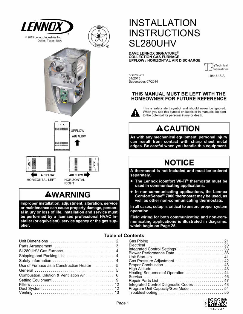
UPFLOW
HORIZONTAL LEFT HORIZONTALRIGHT
AIR FLOW
AIR FLOWAIR FLOW
WARNINGImproper installation, adjustment, alteration, serviceor maintenance can cause property damage, personal injury or loss of life. Installation and service mustbe performed by a licensed professional HVAC installer (or equivalent), service agency or the gas supplier.
INSTALLATIONINSTRUCTIONSSL280UHVDAVE LENNOX SIGNATURE®
COLLECTION GAS FURNACEUPFLOW / HORIZONTAL AIR DISCHARGE
506763-0101/2015Supersedes 07/2014
THIS MANUAL MUST BE LEFT WITH THEHOMEOWNER FOR FUTURE REFERENCE
This a safety alert symbol and should never be ignored.When you see this symbol on labels or in manuals, be alertto the potential for personal injury or death.
CAUTIONAs with any mechanical equipment, personal injurycan result from contact with sharp sheet metaledges. Be careful when you handle this equipment.
NOTICEA thermostat is not included and must be orderedseparately.
� The Lennox icomfort Wi-Fi® thermostat must beused in communicating applications.
� In non-communicating applications, the LennoxComfortSense® 7000 thermostat may be used, aswell as other non-communicating thermostats.
In all cases, setup is critical to ensure proper systemoperation.
Field wiring for both communicating and non-communicating applications is illustrated in diagrams,which begin on Page 25.
Table of ContentsUnit Dimensions 2. . . . . . . . . . . . . . . . . . . . . . . . . . . . . . . .
Parts Arrangement 3. . . . . . . . . . . . . . . . . . . . . . . . . . . . . .
SL280UHV Gas Furnace 4. . . . . . . . . . . . . . . . . . . . . . . . .
Shipping and Packing List 4. . . . . . . . . . . . . . . . . . . . . . . .
Safety Information 4. . . . . . . . . . . . . . . . . . . . . . . . . . . . . . .
Use of Furnace as a Construction Heater 5. . . . . . . . . . .
General 5. . . . . . . . . . . . . . . . . . . . . . . . . . . . . . . . . . . . . . . .
Combustion, Dilution & Ventilation Air 6. . . . . . . . . . . . . .
Setting Equipment 9. . . . . . . . . . . . . . . . . . . . . . . . . . . . . . .Filters 12. . . . . . . . . . . . . . . . . . . . . . . . . . . . . . . . . . . . . . . . . .Duct System 12. . . . . . . . . . . . . . . . . . . . . . . . . . . . . . . . . . . .Venting 13. . . . . . . . . . . . . . . . . . . . . . . . . . . . . . . . . . . . . . . .
Gas Piping 21. . . . . . . . . . . . . . . . . . . . . . . . . . . . . . . . . . . . .Electrical 23. . . . . . . . . . . . . . . . . . . . . . . . . . . . . . . . . . . . . . .Integrated Control Settings 33. . . . . . . . . . . . . . . . . . . . . . .Blower Performance Data 36. . . . . . . . . . . . . . . . . . . . . . . .Unit Start-Up 41. . . . . . . . . . . . . . . . . . . . . . . . . . . . . . . . . . .Gas Pressure Adjustment 42. . . . . . . . . . . . . . . . . . . . . . . .Proper Combustion 43. . . . . . . . . . . . . . . . . . . . . . . . . . . . . .High Altitude 43. . . . . . . . . . . . . . . . . . . . . . . . . . . . . . . . . . . .Heating Sequence of Operation 44. . . . . . . . . . . . . . . . . . .Service 46. . . . . . . . . . . . . . . . . . . . . . . . . . . . . . . . . . . . . . . .Repair Parts List 47. . . . . . . . . . . . . . . . . . . . . . . . . . . . . . . .Integrated Control Diagnostic Codes 48. . . . . . . . . . . . . . .Program Unit Capacity/Size Mode 54. . . . . . . . . . . . . . . . .Troubleshooting 55. . . . . . . . . . . . . . . . . . . . . . . . . . . . . . . . .
Litho U.S.A.
Page 2
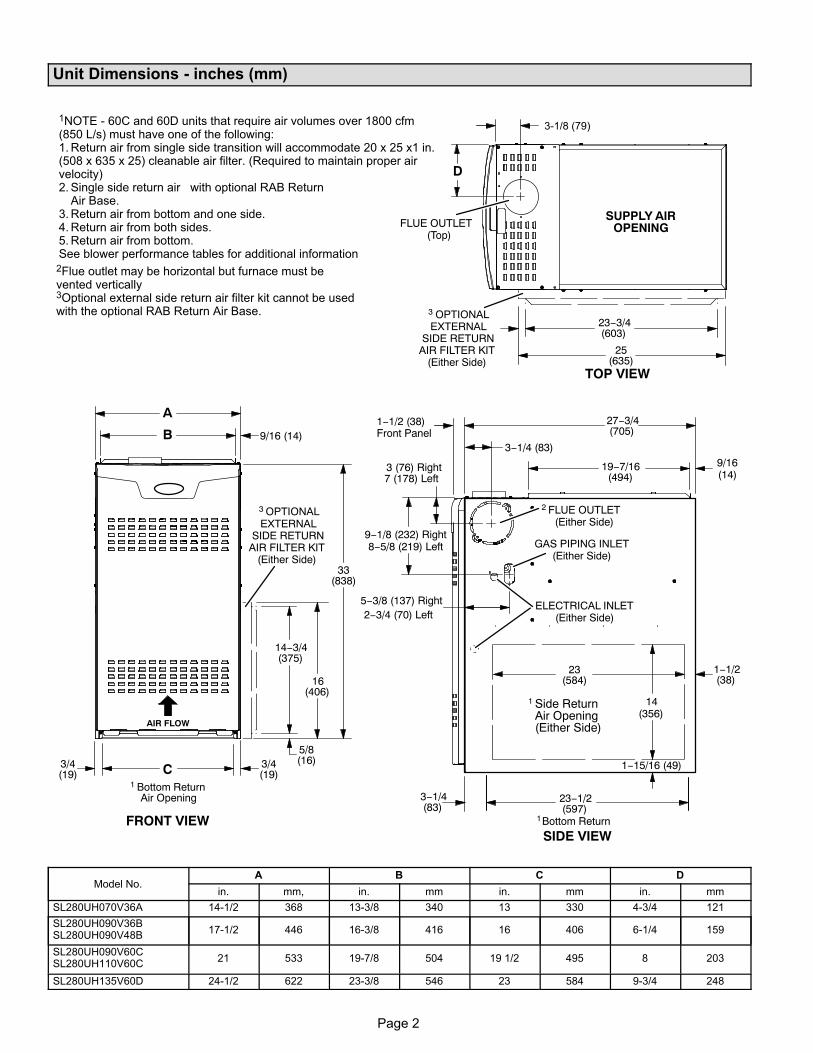
Unit Dimensions - inches (mm)
1NOTE - 60C and 60D units that require air volumes over 1800 cfm(850 L/s) must have one of the following:1. Return air from single side transition will accommodate 20 x 25 x1 in.(508 x 635 x 25) cleanable air filter. (Required to maintain proper airvelocity)2. Single side return air with optional RAB Return
Air Base.3. Return air from bottom and one side.4. Return air from both sides.5. Return air from bottom.See blower performance tables for additional information2Flue outlet may be horizontal but furnace must bevented vertically3Optional external side return air filter kit cannot be usedwith the optional RAB Return Air Base.
AIR FLOW
(19)3/4
(19)1 Bottom Return
Air Opening
FRONT VIEW
A
B 9/16 (14)
C3/4
33(838)
16(406)
14−3/4(375)
3 OPTIONALEXTERNAL
SIDE RETURNAIR FILTER KIT
(Either Side)
5/8(16)
FLUE OUTLET(Top)
SUPPLY AIROPENING
TOP VIEW
D
3 OPTIONALEXTERNAL
SIDE RETURNAIR FILTER KIT
(Either Side)
23−3/4(603)
25(635)
23(584)
GAS PIPING INLET(Either Side)
Side ReturnAir Opening(Either Side)
1Bottom Return
ELECTRICAL INLET(Either Side)
27−3/4(705)
19−7/16(494)
23−1/2(597)
1−1/2(38)
9−1/8 (232) Right8−5/8 (219) Left
5−3/8 (137) Right
1−15/16 (49)
14(356)
9/16(14)
3 (76) Right
2 FLUE OUTLET(Either Side)
3−1/4 (83)
1
3−1/4(83)
SIDE VIEW
3-1/8 (79)
1−1/2 (38)Front Panel
7 (178) Left
2−3/4 (70) Left
Model No.A B C D
in. mm, in. mm in. mm in. mm
SL280UH070V36A 14-1/2 368 13-3/8 340 13 330 4-3/4 121
SL280UH090V36BSL280UH090V48B
17-1/2 446 16-3/8 416 16 406 6-1/4 159
SL280UH090V60CSL280UH110V60C
21 533 19-7/8 504 19 1/2 495 8 203
SL280UH135V60D 24-1/2 622 23-3/8 546 23 584 9-3/4 248
Page 3
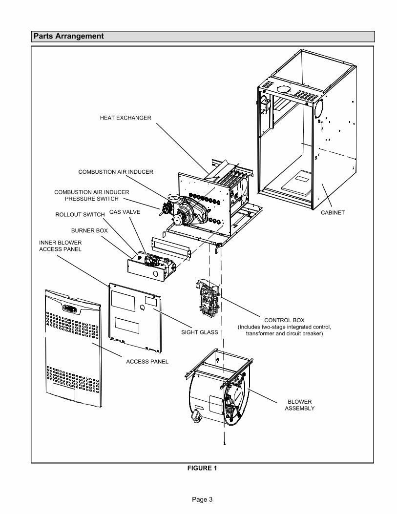
Parts Arrangement
FIGURE 1
HEAT EXCHANGER
CABINET
COMBUSTION AIR INDUCER
BLOWER
ASSEMBLY
BURNER BOX
INNER BLOWER
ACCESS PANEL
ACCESS PANEL
SIGHT GLASS
COMBUSTION AIR INDUCER
PRESSURE SWITCH
GAS VALVE
CONTROL BOX
(Includes two-stage integrated control,
transformer and circuit breaker)
ROLLOUT SWITCH
Page 4
SL280UHV Gas Furnace
The SL280UHV gas furnace is equipped with a two-stage,
variable speed integrated control. the control is compatible
with:
Communicating thermostats - icomfort Wi-Fi®.
Non-comunicating thermostats - ComfortSense or other
conventional thermostats.
Control systems - Harmony III™ Zone Control System
(non-communicating).
Each SL280UHV unit is shipped ready for installation in the
upflow or horizontal position (left or right). The furnace is
shipped with the bottom panel in place. The bottom panel
must be removed if the unit is to be installed in a horizontal
application. The panel may also be removed in upflow ap
plications.
Shipping and Packing List
Package 1 of 1 contains
1 - Assembled SL280UHV unit
1 - Bag assembly containing the following:
2 - Screws
1 - Snap bushing
1 - Snap plug
1 - Wire tie
1 - Vent warning label
1 - Owner's manual and warranty card
The following items may be ordered separately:
1 - Thermostat
1 - Suspension Kit (for horizontal installations)
1 - Propane/LP changeover kit
1 - Return air base
1 - High altitude kit
1 - Side filter kit
Check equipment for shipping damage. If you find any
damage, immediately contact the last carrier.
Safety Information
DANGERDanger of explosion.
There are circumstances in which odorant used withLP/propane gas can lose its scent. In case of a leak,LP/propane gas will settle close to the floor and maybe difficult to smell. An LP/propane leak detectorshould be installed in all LP applications.
WARNINGImproper installation, adjustment, alteration, serviceor maintenance can cause property damage, personal injury or loss of life. Installation and service mustbe performed by a licensed professional installer (orequivalent), service agency or the gas supplier.
CAUTIONAs with any mechanical equipment, personal injurycan result from contact with sharp sheet metaledges. Be careful when you handle this equipment.
Certifications
SL280UHV units are CSA International certified to ANSI
Z21.47.
In the USA, installation of gas furnaces must conform with
local building codes. In the absence of local codes, units
must be installed according to the current National Fuel
Gas Code (ANSI‐Z223.1). The National Fuel Gas Code is
available from the following address:
American National Standards Institute, Inc.
11 West 42nd Street
New York, NY 10036
Clearances
Adequate clearance must be made around the air open
ings into the vestibule area. In order to ensure proper unit
operation, combustion and ventilation air supply must be
provided according to the current National Fuel Gas Code.
Vent installations must be consistent with the venting
tables (in this instruction) and applicable provisions of local
building codes.
This furnace is CSA International certified for installation
clearances to combustible material as listed on the unit
nameplate and in the tables in figures 7 and 11. Accessibil
ity and service clearances must take precedence over fire
protection clearances.
NOTE - For installation on combustible floors, the furnace
shall not be installed directly on carpeting, tile, or other
combustible material other than wood flooring.
Installed Locations
For installation in a residential garage, the furnace must be
installed so that the burner(s) and the ignition source are
located no less than 18 inches (457 mm) above the floor.
The furnace must be located or protected to avoid physical
damage by vehicles. When a furnace is installed in a public
garage, hangar, or other building that has a hazardous at
mosphere, the furnace must be installed according to rec
ommended good practice requirements and current Na
tional Fuel Gas Code.
Temperature Rise
NOTE - Furnace must be adjusted to obtain a temperature
rise(high and low fire) within the range(s) specified on the
unit nameplate. Failure to do so may cause erratic limit op
eration and may result in premature heat exchanger fail
ure.
This SL280UHV furnace must be installed so that its elec
trical components are protected from water.
Page 5
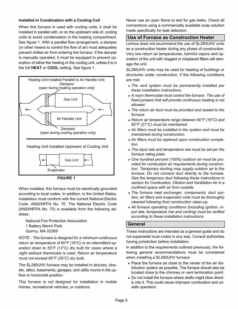
Installed in Combination with a Cooling Coil
When this furnace is used with cooling units, it shall be
installed in parallel with, or on the upstream side of, cooling
units to avoid condensation in the heating compartment.
See figure 1. With a parallel flow arrangement, a damper
(or other means to control the flow of air) must adequately
prevent chilled air from entering the furnace. If the damper
is manually operated, it must be equipped to prevent op
eration of either the heating or the cooling unit, unless it is in
the full HEAT or COOL setting. See figure 1.
FIGURE 1
Gas Unit
Heating Unit Installed Upstream of Cooling Unit
Gas Unit
Dampers(open during heating operation only)
Dampers(open during cooling operation only)
Heating Unit Installed Parallell to Air Handler Unit
Air Handler Unit
Evaporator
When installed, this furnace must be electrically grounded
according to local codes. In addition, in the United States,
installation must conform with the current National Electric
Code, ANSI/NFPA No. 70. The National Electric Code
(ANSI/NFPA No. 70) is available from the following ad
dress:
National Fire Protection Association
1 Battery March Park
Quincy, MA 02269
NOTE - This furnace is designed for a minimum continuous
return air temperature of 60°F (16°C) or an intermittent op
eration down to 55°F (13°C) dry bulb for cases where a
night setback thermostat is used. Return air temperature
must not exceed 85°F (29°C) dry bulb.
The SL280UHV furnace may be installed in alcoves, clos
ets, attics, basements, garages, and utility rooms in the up
flow or horizontal position.
This furnace is not designed for installation in mobile
homes, recreational vehicles, or outdoors.
Never use an open flame to test for gas leaks. Check all
connections using a commercially available soap solution
made specifically for leak detection.
Use of Furnace as Construction Heater
Lennox does not recommend the use of SL280UHV units
as a construction heater during any phase of construction.
Very low return air temperatures, harmful vapors and op
eration of the unit with clogged or misplaced filters will dam
age the unit.
SL280UHV units may be used for heating of buildings or
structures under construction, if the following conditions
are met:
� The vent system must be permanently installed per
these installation instructions.
� A room thermostat must control the furnace. The use of
fixed jumpers that will provide continuous heating is not
allowed.
� The return air duct must be provided and sealed to the
furnace.
� Return air temperature range between 60°F (16°C) and
80°F (27°C) must be maintained.
� Air filters must be installed in the system and must be
maintained during construction.
� Air filters must be replaced upon construction comple
tion.
� The input rate and temperature rise must be set per the
furnace rating plate.
� One hundred percent (100%) outdoor air must be pro
vided for combustion air requirements during construc
tion. Temporary ducting may supply outdoor air to the
furnace. Do not connect duct directly to the furnace.
Size the temporary duct following these instructions in
section for Combustion, Dilution and Ventilation Air in a
confined space with air from outside.
� The furnace heat exchanger, components, duct sys
tem, air filters and evaporator coils must be thoroughly
cleaned following final construction clean-up.
� All furnace operating conditions (including ignition, in
put rate, temperature rise and venting) must be verified
according to these installation instructions.
General
These instructions are intended as a general guide and do
not supersede local codes in any way. Consult authorities
having jurisdiction before installation.
In addition to the requirements outlined previously, the fol
lowing general recommendations must be considered
when installing a SL280UHV furnace:
� Place the furnace as close to the center of the air dis
tribution system as possible. The furnace should also be
located close to the chimney or vent termination point.
� Do not install the furnace where drafts might blow direct
ly into it. This could cause improper combustion and un
safe operation.
Page 6
� Do not block the furnace combustion air openings with
clothing, boxes, doors, etc. Air is needed for proper
combustion and safe unit operation.
� When the furnace is installed in an attic or other insu
lated space, keep insulation away from the furnace.
• Please consult the manufacturer of your evaporator coil
for their recommendations on distance required
between the heat exchanger and their drain pan. Ad
equate space must be provided between the drain pan
and the furnace heat exchanger.
NOTE - The Commonwealth of Massachusetts stipu
lates these additional requirements:
� Gas furnaces shall be installed by a licensed plumb
er or fitter only.
� The gas cock must be “T handle” type.
� When a furnace is installed in an attic, the passage
way to and service area surrounding the equipment
shall be floored.
WARNINGThe State of California has determined that this product may contain or produce a chemical or chemicals,in very low doses, which may cause serious illnessor death. It may also cause cancer, birth defects orreproductive harm.
Combustion, Dilution & Ventilation Air
In the past, there was no problem in bringing in sufficient
outdoor air for combustion. Infiltration provided all the air
that was needed. In today's homes, tight construction prac
tices make it necessary to bring in air from outside for com
bustion. Take into account that exhaust fans, appliance
vents, chimneys, and fireplaces force additional air that
could be used for combustion out of the house. Unless out
side air is brought into the house for combustion, negative
pressure (outside pressure is greater than inside pressure)
will build to the point that a downdraft can occur in the fur
nace vent pipe or chimney. As a result, combustion gases
enter the living space creating a potentially dangerous situ
ation.
In the absence of local codes concerning air for combus
tion and ventilation, use the guidelines and procedures in
this section to install SL280UHV furnaces to ensure effi
cient and safe operation. You must consider combustion
air needs and requirements for exhaust vents and gas pip
ing. A portion of this information has been reprinted with
permission from the National Fuel Gas Code
(ANSI‐Z223.1). This reprinted material is not the complete
and official position of the ANSI on the referenced subject,
which is represented only by the standard in its entirety.
CAUTIONDo not install the furnace in a corrosive or contaminated atmosphere. Meet all combustion and ventilation air requirements, as well as all local codes.
CAUTIONInsufficient combustion air can cause headaches,nausea, dizziness or asphyxiation. It will also causeexcess water in the heat exchanger resulting in rusting and premature heat exchanger failure. Excessiveexposure to contaminated combustion air will resultin safety and performance related problems. Avoidexposure to the following substances in the combustion air supply:
Permanent wave solutionsChlorinated waxes and cleanersChlorine base swimming pool chemicalsWater softening chemicalsDe‐icing salts or chemicalsCarbon tetrachlorideHalogen type refrigerantsCleaning solvents (such as perchloroethylene)Printing inks, paint removers, varnishes, etc.Hydrochloric acidCements and gluesAntistatic fabric softeners for clothes dryersMasonry acid washing materials
All gas‐fired appliances require air for the combustion pro
cess. If sufficient combustion air is not available, the fur
nace or other appliances will operate inefficiently and un
safely. Enough air must be provided to meet the needs of
all fuel‐burning appliances and appliances such as ex
haust fans which force air out of the house. When fire
places, exhaust fans, or clothes dryers are used at the
same time as the furnace, much more air is necessary to
ensure proper combustion and to prevent a downdraft. In
sufficient air causes incomplete combustion which can re
sult in carbon monoxide.
In addition to providing combustion air, fresh outdoor air di
lutes contaminants in the indoor air. These contaminants
may include bleaches, adhesives, detergents, solvents
and other contaminants which can corrode furnace compo
nents.
The requirements for providing air for combustion and ven
tilation depend largely on whether the furnace is installed in
an unconfined or a confined space.
Page 7
Unconfined Space
An unconfined space is an area such as a basement or
large equipment room with a volume greater than 50 cubic
feet (1.42 m3) per 1,000 Btu (.29 kW) per hour of the com
bined input rating of all appliances installed in that space.
This space also includes adjacent rooms which are not
separated by a door. Though an area may appear to be un
confined, it might be necessary to bring in outdoor air for
combustion if the structure does not provide enough air by
infiltration. If the furnace is located in a building of tight
construction with weather stripping and caulking around
the windows and doors, follow the procedures in the air
from outside section.
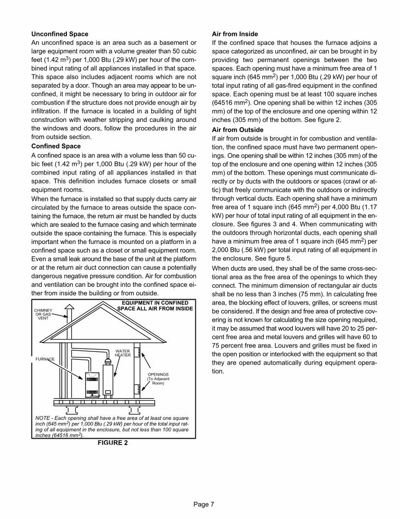
Confined Space
A confined space is an area with a volume less than 50 cu
bic feet (1.42 m3) per 1,000 Btu (.29 kW) per hour of the
combined input rating of all appliances installed in that
space. This definition includes furnace closets or small
equipment rooms.
When the furnace is installed so that supply ducts carry air
circulated by the furnace to areas outside the space con
taining the furnace, the return air must be handled by ducts
which are sealed to the furnace casing and which terminate
outside the space containing the furnace. This is especially
important when the furnace is mounted on a platform in a
confined space such as a closet or small equipment room.
Even a small leak around the base of the unit at the platform
or at the return air duct connection can cause a potentially
dangerous negative pressure condition. Air for combustion
and ventilation can be brought into the confined space ei
ther from inside the building or from outside.
EQUIPMENT IN CONFINEDSPACE ALL AIR FROM INSIDECHIMNEY
OR GASVENT
FURNACE
WATERHEATER
OPENINGS(To Adjacent
Room)
NOTE - Each opening shall have a free area of at least one squareinch (645 mm2) per 1,000 Btu (.29 kW) per hour of the total input rating of all equipment in the enclosure, but not less than 100 squareinches (64516 mm2).
AIR FLOW
FIGURE 2
Air from Inside
If the confined space that houses the furnace adjoins a
space categorized as unconfined, air can be brought in by
providing two permanent openings between the two
spaces. Each opening must have a minimum free area of 1
square inch (645 mm2) per 1,000 Btu (.29 kW) per hour of
total input rating of all gas-fired equipment in the confined
space. Each opening must be at least 100 square inches
(64516 mm2). One opening shall be within 12 inches (305
mm) of the top of the enclosure and one opening within 12
inches (305 mm) of the bottom. See figure 2.
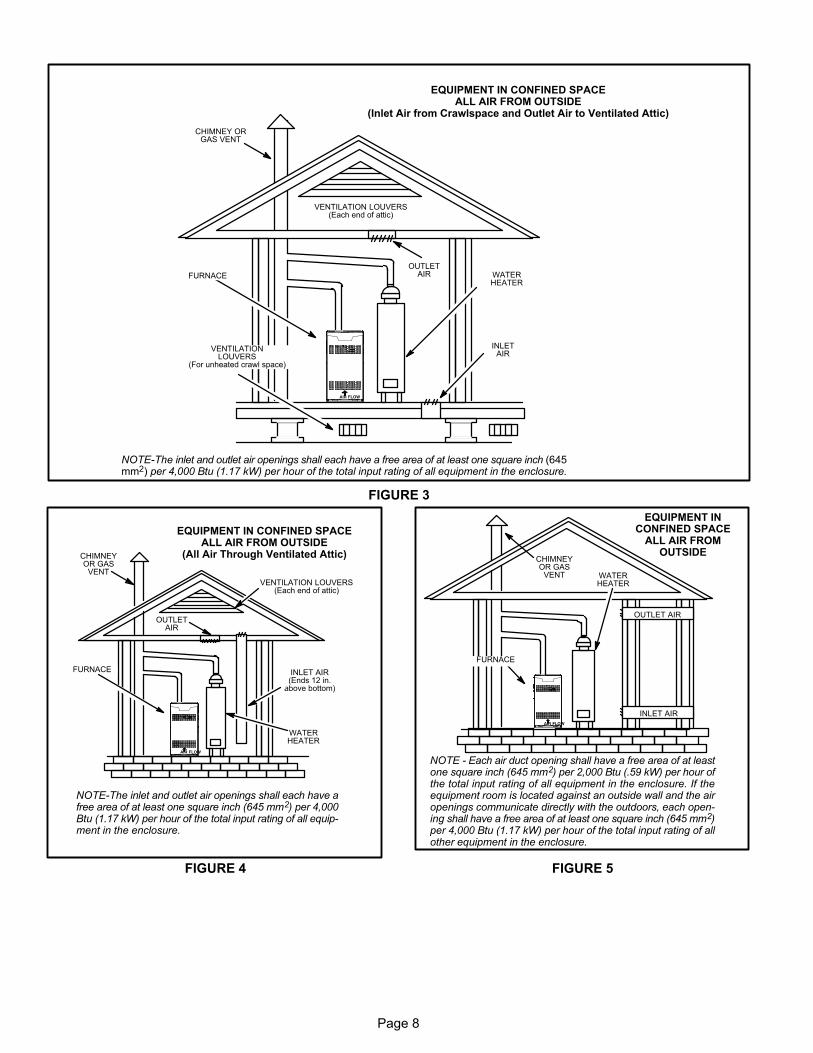
Air from Outside
If air from outside is brought in for combustion and ventila
tion, the confined space must have two permanent open
ings. One opening shall be within 12 inches (305 mm) of the
top of the enclosure and one opening within 12 inches (305
mm) of the bottom. These openings must communicate di
rectly or by ducts with the outdoors or spaces (crawl or at
tic) that freely communicate with the outdoors or indirectly
through vertical ducts. Each opening shall have a minimum
free area of 1 square inch (645 mm2) per 4,000 Btu (1.17
kW) per hour of total input rating of all equipment in the en
closure. See figures 3 and 4. When communicating with
the outdoors through horizontal ducts, each opening shall
have a minimum free area of 1 square inch (645 mm2) per
2,000 Btu (.56 kW) per total input rating of all equipment in
the enclosure. See figure 5.
When ducts are used, they shall be of the same cross-sec
tional area as the free area of the openings to which they
connect. The minimum dimension of rectangular air ducts
shall be no less than 3 inches (75 mm). In calculating free
area, the blocking effect of louvers, grilles, or screens must
be considered. If the design and free area of protective cov
ering is not known for calculating the size opening required,
it may be assumed that wood louvers will have 20 to 25 per
cent free area and metal louvers and grilles will have 60 to
75 percent free area. Louvers and grilles must be fixed in
the open position or interlocked with the equipment so that
they are opened automatically during equipment opera
tion.
Page 8
EQUIPMENT IN CONFINED SPACEALL AIR FROM OUTSIDE
(Inlet Air from Crawlspace and Outlet Air to Ventilated Attic)
NOTE-The inlet and outlet air openings shall each have a free area of at least one square inch (645mm2) per 4,000 Btu (1.17 kW) per hour of the total input rating of all equipment in the enclosure.
VENTILATION LOUVERS(Each end of attic)
OUTLETAIR WATER
HEATER
INLETAIR
CHIMNEY ORGAS VENT
FURNACE
VENTILATIONLOUVERS
(For unheated crawl space)
AIR FLOW
FIGURE 3
EQUIPMENT IN CONFINED SPACEALL AIR FROM OUTSIDE
(All Air Through Ventilated Attic)
NOTE-The inlet and outlet air openings shall each have afree area of at least one square inch (645 mm2) per 4,000Btu (1.17 kW) per hour of the total input rating of all equipment in the enclosure.
CHIMNEYOR GAS
VENT
WATERHEATER
OUTLETAIR
VENTILATION LOUVERS(Each end of attic)
INLET AIR(Ends 12 in.
above bottom)
FURNACE
AIR FLOW
FIGURE 4
EQUIPMENT INCONFINED SPACE
ALL AIR FROMOUTSIDE
OUTLET AIR
INLET AIR
WATERHEATER
CHIMNEYOR GAS
VENT
NOTE - Each air duct opening shall have a free area of at leastone square inch (645 mm2) per 2,000 Btu (.59 kW) per hour ofthe total input rating of all equipment in the enclosure. If theequipment room is located against an outside wall and the airopenings communicate directly with the outdoors, each opening shall have a free area of at least one square inch (645 mm2)per 4,000 Btu (1.17 kW) per hour of the total input rating of allother equipment in the enclosure.
FURNACE
AIR FLOW
FIGURE 5
Page 9
Setting Equipment
WARNINGDo not install the furnace on its front or its back. Donot connect the return air ducts to the back of the furnace. Doing so will adversely affect the operation ofthe safety control devices, which could result in personal injury or death.
The SL280UHV gas furnace can be installed as shipped in
either the upflow position or the horizontal position.
Select a location that allows for the required clearances
that are listed on the unit nameplate. Also consider gas
supply connections, electrical supply, vent connection, and
installation and service clearances [24 inches (610 mm) at
unit front]. The unit must be level.
NOTE - Units with 1/2 hp blower motors are equipped with
three flexible legs and one rigid leg. See figure 6. The rigid
leg is equipped with a shipping bolt and a flat white plastic
washer (rather than the rubber mounting grommet used
with a flexible mounting leg). The bolt and washer must
be removed before the furnace is placed into opera
tion. After the bolt and washer have been removed, the rig
id leg will not touch the blower housing.
FIGURE 6
RIGID LEGremove shipping bolt and washer
SL280UHV07036A andSL280UHV09036B WITH 1/2 HP
BLOWER MOTOR
Upflow Applications
Allow for clearances to combustible materials as indicated
on the unit nameplate. Minimum clearances for closet or al
cove installations are shown in figure 7.
Upflow Application Installation Clearances
Top
Bottom
Left Side Right Side
AIR FLOW
Type of VentConnector
Type C Type B1
Top 1 in. (25 mm) 1 in. (25 mm)
*Front 2-1/4 in. (57 mm)** 2-1/4 in. (57 mm)
Back 0 0
Sides 0† 0
Vent 6 in. (152 mm) 1 in. (25 mm)
Floor 0‡ 0‡
*Front clearance in alcove installation must be 24 in. (610 mm).Maintain a minimum of 24 in. (610 mm) for front service access.** 3-1/4 in. if single wall vent pipe is used.‡For installation on a combustible floor, do not install the furnacedirectly on carpeting, tile or other combustible materials otherthan wood flooring.†Left side requires 3 inches if a single wall vent is used on 14-1/2inch cabinets, or 2 in. if a single wall vent is used on 17-1/2 in. cabinets.
FIGURE 7
Page 10
Return Air -- Upflow Applications
Return air can be brought in through the bottom or either
side of the furnace installed in an upflow application. If the
furnace is installed on a platform with bottom return, make
an airtight seal between the bottom of the furnace and the
platform to ensure that the furnace operates properly and
safely. The furnace is equipped with a removable bottom
panel to facilitate installation.
Markings are provided on both sides of the furnace cabinet
for installations that require side return air. Cut the furnace
cabinet at the maximum dimensions shown on page 2.
NOTE - 60C and 60D units that require air volumes over 1800
cfm (850 L/s) must have one of the following:
1 - Return air from single side with transition which will
accommodate 20 x 25 x 1 in. (508 x 635 x 25 mm) clean
able air filter. (Required to maintain proper air velocity.)
See figure 8.
2 - Return air from single side with optional RAB Return
Air Base. See figure 9.
3 - Return air from bottom and one side.
4 - Return air from both sides.
5 - Return air from bottom.
Refer to Engineering Handbook for additional information.FIGURE 8
Return AirPlenum
Transition
20” X 25” X 1”(508mm X635mm X 25mm)
Cleanable Filter
AIR FLOW
Single Side Return Air(with transition and filter)
Optional Return Air Base(Upflow Applications Only -- For use with A, B, C and D cabinets)
FIGURE 9
NOTE- Optional Side Return Air Filter Kits are not for use with Optional Return Air Base.1 Both the unit return air opening and the base return air opening must be covered by a single plenum or IAQ cabinet.
Minimum unit side return air opening dimensions for units requiring 1800 cfm or more of air (W x H): 23 x 11 in. (584 x 279 mm).The opening can be cut as needed to accommodate plenum or IAQ cabinet while maintaining dimensions shown.Side return air openings must be cut in the field. There are cutting guides stenciled on the cabinet for the side return airopening. The size of the opening must not extend beyond the markings on the furnace cabinet.
2 To minimize pressure drop, the largest opening height possible (up to 14 inches) is preferred.
OPTIONALRETURN AIR BASE
FURNACEFRONT
AIR FLOW
14−1/2” (368) A Width (65W75)17−1/2” (446) B Width (50W98)
21”− (533) C Width (50W99)24−1/2”− (622) D Width (51W00)
1 Unit side return airOpening
SIDE VIEW
3−1/4(83)
1 23 (584)Overall
(Maximum)
(584)23
3/4(19)
1 22−7/16(570)
Overall(Maximum)
SIDE RETURNAIR OPENINGS
(Either Side)
5−5/8(143)
1 Minimum11 (279)
2 Maximum14 (356)
(683)26−7/8
7−1/4(184)
IF BASEIS USED
WITHOUTIAQ CABINET,
A SINGLERETURN AIR
PLENUMMUST
COVER BOTHUNIT ANDRETURNAIR BASE
OPENINGS
INDOOR AIR
Page 11
Removing the Bottom Panel
Remove the two screws that secure the bottom cap to the
furnace. Pivot the bottom cap down to release the bottom
panel. Once the bottom panel has been removed, reinstall
the bottom cap. See figure 10.
Removing the Bottom Panel
FIGURE 10
Screw
Bottom Panel
Bottom Cap
Horizontal ApplicationInstallation Clearances
Top
Bottom
LeftEnd
RightEnd
AIR
FL
OW
Vent ConnectorType
Type C Type B1
Top 0 0
*Front 2-1/4 in. (57 mm)** 2-14 in. (57 mm)
Back 0 0
Ends 2 in. (51 mm) 2 in. (51 mm)
Vent 6 in. (152 mm) 1 in. (25 mm)
Floor 0‡ 0‡
*Front clearance in alcove installation must be 24 in. (610 mm).Maintain a minimum of 24 in. (610 mm) for front service access.** 3-1/4 in. if single wall vent pipe is used.‡For installations on a combustible floor, do not install the furnace directly on carpeting, tile or other combustible materials other than wood flooring.
FIGURE 11
Horizontal Applications
The SL280UHV furnace can be installed in horizontal ap
plications. Order kit number 51W10 (or use equivalent)
from Lennox.
Allow for clearances to combustible materials as indicated
on the unit nameplate. Minimum clearances for closet or al
cove installations are shown in figure 11.
This furnace may be installed in either an attic or a crawl
space. Either suspend the furnace from roof rafters or floor
joists, as shown in figure 12, or install the furnace on a plat
form, as shown in figure 13.
Typical Horizontal ApplicationUnit Suspended in Attic or Crawlspace
FIGURE 12
Bracket
Bottom Cap
Metal Strap
3/16 inch
Air Flow
NOTE - Heavy-gauge perforated sheet metal straps may
be used to suspend the unit from roof rafters or ceiling
joists. When straps are used to suspend the unit in this way,
support must be provided for both the ends. The straps
must not interfere with the plenum or exhaust piping instal
lation. Cooling coils and supply and return air plenums
must be supported separately.
NOTE - When the furnace is installed on a platform in a
crawlspace, it must be elevated enough to avoid water
damage and to allow the evaporator coil to drain.
Return Air -- Horizontal Applications
Return air must be brought in through the end of a furnace
installed in a horizontal application. The furnace is
equipped with a removable bottom panel to facilitate instal
lation. See figure 10.
CAUTIONIf this unit is being installed in a space serviced byan exhaust fan, power exhaust fan, or other devicewhich may create a negative pressure in the space,take care when sizing the inlet air opening. The inlet air opening must be sized to accommodate themaximum volume of exhausted air as well as themaximum volume of combustion air required forall gas appliances serviced by this space.
Page 12
Horizontal ApplicationUnit Installed on Platform
FIGURE 13
clearances.
GASENTRY VENT
PIPE
See the unit nameplate forLine contact is permissible
SERVICE PLATFORM
WARNINGImproper installation of the furnace can result in personal injury or death. Combustion and flue productsmust never be allowed to enter the return air systemor the living space. Use screws and joint tape to sealthe return air system to the furnace.In platform installations with bottom return air, thefurnace should be sealed airtight to the return air plenum. A door must never be used as a portion of thereturn air duct system. The base must provide astable support and an airtight seal to the furnace. Allow absolutely no sagging, cracks, gaps, etc.The return and supply air duct systems must neverbe connected to or from other heating devices suchas a fireplace or stove, etc. Fire, explosion, carbonmonoxide poisoning, personal injury and/or property damage could result.
WARNINGThe inner blower panel must be securely in placewhen the blower and burners are operating. Gasfumes, which could contain carbon monoxide, canbe drawn into living space resulting in personal injury or death.
Filters
This unit is not equipped with a filter or rack. A field-pro
vided high-velocity filter is required for the unit to operate
properly. Table 1 lists recommended filter sizes.
A filter must be in place any time the unit is operating.
IMPORTANTIf a highefficiency filter is being installed as part ofthis system to ensure better indoor air quality, the filter must be properly sized. Highefficiency filtershave a higher static pressure drop than standardefficiency glass/foam filters. If the pressure drop is toogreat, system capacity and performance may be reduced. The pressure drop may also cause the limit totrip more frequently during the winter and the indoorcoil to freeze in the summer, resulting in an increasein the number of service calls.
Before using any filter with this system, check thespecifications provided by the filter manufactureragainst the data given in the appropriate LennoxProduct Specifications bulletin. Additional information is provided in Service and Application NoteACC002 (August 2000).
TABLE 1
FurnaceCabinet Width
Filter Size
Side Return Bottom Return
14-1/2” 16 X 25 X 1 (1) 14 X 25 X 1 (1)
17-1/2” 16 X 25 X 1 (1) 16 X 25 X 1 (1)
21” 16 X 25 X 1 (1) 20 X 25 X 1 (1)
24-1/2” 16 X 25 X 1 (2) 24 X 25 X 1 (1)
Duct System
Use industry‐approved standards (such as those pub
lished by Air Conditioning Contractors of America or Ameri
can Society of Heating, Refrigerating and Air Conditioning
Engineers) to size and install the supply and return air duct
system. This will result in a quiet and low‐static system that
has uniform air distribution.
NOTE - Do not operate the furnace in the heating mode
with an external static pressure that exceeds 0.8 inches
w.c. Higher external static pressures may cause erratic lim
it operation.
Supply Air Plenum
If the furnace is installed without a cooling coil, a removable
access panel must be installed in the supply air duct. The
access panel should be large enough to permit inspection
(either by smoke or reflected light) of the heat exchanger
for leaks after the furnace is installed. The furnace access
panel must always be in place when the furnace is operat
ing and it must not allow leaks into the supply air duct sys
tem.
Return Air Plenum
NOTE - Return air must not be drawn from a roomwhere this furnace, or any other gas-fueled appliance(i.e., water heater), or carbon monoxide- producing device (i.e., wood fireplace) is installed.
When return air is drawn from a room, a negative pressure
is created in the room. If a gas appliance is operating in a
room with negative pressure, the flue products can be
pulled back down the vent pipe and into the room. This re
Page 13
verse flow of the flue gas may result in incomplete combus
tion and the formation of carbon monoxide gas. This toxic
gas might then be distributed throughout the house by the
furnace duct system.
In upflow applications, the return air can be brought in
through the bottom or either side of the furnace. If a furnace
with bottom return air is installed on a platform, make an air
tight seal between the bottom of the furnace and the plat
form to ensure that the unit operates properly and safely.
Use fiberglass sealing strips, caulking, or equivalent seal
ing method between the plenum and the furnace cabinet to
ensure a tight seal. If a filter is installed, size the return air
duct to fit the filter frame.
Venting
A 4-inch diameter flue transition is factory‐installed on thecombustion air inducer outlet of all models. Figure 15shows the combustion air inducer as shipped from thefactory.
FIGURE 14
Mounting Screws Location
mounting screws
mounting screw
IMPORTANTThe unit will not vent properly with the flue transitionpointed down in the 6 o'clock position.The combustion air inducer may be rotated clockwise or counterclockwise by 90° to allow for top orside vent discharge in all applications. When the unitis installed, the flue transition must be in the 9o'clock, 12 o'clock or 3 o'clock position.
If necessary reposition the combustion air inducer, pressure switch and or make up box as needed per the following steps and see figures 15 through 21.
1 - Remove the four mounting screws (figure 14) whichsecure the combustion air inducer / pressure switchassembly to the orifice plate. Lift and rotate the assembly 90 degrees clockwise or counter clockwise to eitherthe 3 o'clock position or to 9 o'clock position and re-secure with four screws. Gasket should be left in place.
2 - Use tin snips to cut preferred opening on the cabinetfor repositioning the flue outlet. Use the cut out pieceas a cover plate to patch unused opening on cabinet.
UPFlow Position
FIGURE 15
UPFLOW POSITION
Top Vent Discharge
FLOWAIR
collector box
vent pipe
fluetransition
pressureswitch
make-upbox
UPFLOW POSITION
Left Side Vent Discharge
FIGURE 16
� Gas supply piping must be brought into the unit from the rightside in order to accommodate the flue pipe.
� Remove make-up box assembly (2 screws) and cut wire tie tofree make-up box wires. Re-install make-up box on other sideof cabinet.
� Re-secure make-up box wires, either pulling excess wiresthrough the blower compartment and securing with suppliedwire tie, or coil excess wire and secure to the gas manifold.
FLOWAIR
make-upbox
pressureswitch
fluetransition
vent pipe
cover plate collector box
Page 14
UPFLOW POSITION
Right Side Vent Discharge
FIGURE 17
� Pressure switch tubing may be too long. Cut tofit , then re-attach to barbed fitting on pressureswitch. Tubing must not be allowed to sag.
FLOWAIR
cover plateflue transition
vent pipe
pressureswitch
make-upbox
collector box
Horizontal Position
FIGURE 18
HORIZONTAL LEFT POSITION
Top Vent Discharge
� Disconnect pressure switch hose from barbed fitting on the pressure switch assembly. Remove pressure switch assembly (1screw) and cut wire tie to free pressure switch wires. Re-installpressure switch on the other side of orifice plate and re-connectpressure switch hose.
� Re-secure pressure switch wires by either pulling excess wiresthrough the blower compartment and securing with supplied wiretie or coil excess wire and secure to the gas manifold.
pressure switchvent pipe
fluetransition
cover plate
make-up box collector box
FLOW
AIR
FIGURE 19
make-up box collector box
flue transition
pressure switch
HORIZONTAL LEFT POSITION
Side Vent Discharge
� Disconnect pressure switch hose from barbed fitting on thepressure switch assembly. Remove pressure switch assembly(1 screw) and cut wire tie to free pressure switch wires. Re-install pressure switch on the other side of orifice plate and re-connect pressure switch hose.
� Re-secure pressure switch wires by either pulling excess wiresthrough the blower compartment and securing with suppliedwire tie, or coil excess wire and secure to the gas manifold.
FLOW
AIR
HORIZONTAL RIGHT POSITION
Top Vent Discharge
FIGURE 20
� Gas supply piping must be brought into the unit from the bottomin order to accommodate the flue pipe.
� Remove make-up box assembly (2 screws) and cut wire tie tofree make-up box wires. Re-install make-up box on other sideof cabinet.
� Re-secure make-up box wires by either pulling excess wiresthrough the blower compartment and securing with suppliedwire tie, or coil excess wire and secure to the gas manifold.
FLOW
AIR
flue transition
vent pipe
pressure switch
cover plate
make-up box
collector box
Page 15
HORIZONTAL RIGHT POSITION
Side Vent Discharge
FIGURE 21
FLOW
AIR
pressure switch
flue transition
collector box
make up box
The SL280UHV series units are classified as fan-assisted
Category I furnaces when vertically vented according to
the latest edition of National Fuel Gas Code (NFPA 54 /
ANSI Z223.1) in the USA. A fan-assisted Category I fur
nace is an appliance equipped with an integral mechanical
means to either draw or force combustion products through
the combustion chamber and/or heat exchanger. The
SL280UHV is not approved for use with horizontal venting..
NOTE - Use these instructions as a guide. They do not su
persede local codes. This furnace must be vented accord
ing to all local codes these installation instructions, and the
provided venting tables in these instructions
The venting tables in this manual were extracted from the
National Fuel Gas Code (NFPA 54 / ANSI Z223.1) and are
provided as a guide for proper vent installation. Proper ap
plication, termination, construction and location of vents
must conform to local codes having jurisdiction. In the ab
sence of local codes, the NFGC serves as the defining doc
ument.
Refer to the tables and the venting information contained in
these instructions to properly size and install the venting
system.
IMPORTANTOnce the venting system is installed, attach the “Disconnected Vent” warning sticker to a visible area ofthe plenum near the vent pipe. See figure 22. Thewarning sticker is provided in the bag assembly. Order kit 66W04 for additional stickers.
WARNINGAsphyxiation hazard. The exhaust vent for this furnace must be securely connected to the furnace fluetransition at all times.
FLUE TRANSITIONCOLLAR
VENT CONNECTION
VENT PIPE(min. 6” length)
“DISCONNECTED VENT”WARNINGSTICKER
FIGURE 22Use self-drilling sheet metal screws or a mechanical fastener to firmly secure the vent pipe to the round collar of theflue transition. If self-drilling screws are used to attach thevent pipe, it is recommended that three be used. Drive oneself-drilling screw through the front and one through eachside of the vent pipe and collar. See figures 19, 21 and 22.
Install the first vent connector elbow at a minimum of sixinches (152 mm) from the furnace vent outlet. See figure22.
Venting Using a Masonry Chimney
The following additional requirements apply when a linedmasonry chimney is used to vent this furnace.
Masonry chimneys used to vent Category I central furnaces must be either tile‐lined or lined with a listed metallining system or dedicated gas vent. Unlined masonrychimneys are prohibited. See figures 24 and 23 for common venting.
A chimney with one or more sides exposed to the outside ofthe structure is considered to be an exterior chimney.
An exterior masonry chimney that is not tile-lined must be
lined with B1 vent or a listed insulated flexible metal vent.
An exterior tile-lined chimney that is sealed and capped
may be lined with a listed uninsulated flexible metal vent.
If the existing chimney will not accommodate a listed metal
liner, either the chimney must be rebuilt to accommodate
one of these liners or an alternate approved venting meth
od must be found.
Insulation for the flexible vent pipe must be an encapsu
lated fiberglass sleeve recommended by the flexible vent
pipe manufacturer. See figure 24.
Page 16
FIGURE 23
Common Venting Using Tile-Lined Interior Masonry Chimney and Combined Vent Connector
MINIMUM LENGTH = AS SHORT AS PRACTICAL. FOR MAXIMUM LENGTH SEE NOTE TO LEFT
INTERIOR TILE-LINEDMASONRY CHIMNEY
NOTE - the chimney must be properlysized per provided venting tables orlined with listed metal lining system.
PERMANENTLYSEALED FIREPLACEOPENING
VENTCONNECTOR
NOTE- Refer to provided venting tablesfor installations.
FURNACE
OTHERAPPLIANCE
AIR FLOW
FIGURE 24
Common Venting Using Metal-Lined Masonry Chimney
4 in. (102 mm)minimum
MIN. LENGTH -- ASSHORT AS PRACTICAL
MAX. LENGTH-- SEE NOTE 1
BELOW.
SEALED
PERMANENTLYSEALED FIREPLACE
OPENING
EXTERIORCHIMNEY WITH
METALLINER
VENT CONNECTOR
NOTE 1 - Refer to the provided venting tables for installations. Referto the capacity requirements shown in the provided venting tables.
OTHERAPPLIANCE
FURNACE
5 ft. (1.5 m)minimum
AIR FLOW
DO NOT insulate the space between the liner and the
chimney wall with puffed mica or any other loose gran
ular insulating material
IMPORTANTSINGLE appliance venting of a fan‐assisted furnaceinto a tile‐lined masonry chimney (interior or outsidewall) is PROHIBITED. The chimney must first be linedwith either type B1 vent or an insulated single wallflexible vent lining system which has been sized according to the provided venting tables and the ventpipe manufacturer's instructions.
A fan-assisted furnace may be commonly vented into anexisting lined masonry chimney if the following conditionsare met:
� The chimney is currently serving at least one drafthoodequipped appliance
� The vent connectors and chimney are sized accordingto the provided venting tables.
If type B1 double‐wall vent is used inside a chimney, no oth
er appliance can be vented into the chimney. The outer wall
of type B1 vent pipe must not be exposed to flue products.
A type B1 vent or masonry chimney liner shall terminate
above the roof surface with a listed cap or a listed roof as
sembly according to the terms of their respective listings
and the vent manufacturer's instructions.
When inspection reveals that an existing chimney is not
safe for the intended purpose, it shall be rebuilt to conform
to nationally recognized standards, lined or relined with
suitable materials, or replaced with a gas vent or chimney
suitable for venting SL280UHV series units. The chimney
passageway must be checked periodically to ensure that it
is clear and free of obstructions.
Do not install a manual damper, barometric draft regulator,
or flue restrictor between the furnace and the chimney.
Never connect a Category I appliance to a chimney that isservicing a solid-fuel appliance. If a fireplace chimney flueis used to vent this appliance, the fireplace opening mustbe permanently sealed.
A type B or listed chimney lining system that passesthrough an unused masonry chimney flue is not consideredto be exposed to the outdoors.
General Venting Requirements
Vent all SL280UHV furnaces according to these instruc
tions:
1 - Vent diameter recommendations and maximum allow
able piping runs are found in the provided venting
tables.
Page 17
2 - In no case should the vent or vent connector diameter
be less than the diameter specified in the provided
venting tables.
3 - The minimum vent capacity determined by the sizing
tables must be less than the low fire input rating and the
maximum vent capacity must be greater than the high
fire input rating.
4 - Single appliance vents - If the vertical vent or tile‐lined
chimney has a larger diameter or flow area than the
vent connector, use the vertical vent diameter to de
termine the minimum vent capacity and the vent
connector diameter to determine the maximum vent
capacity. The flow area of the vertical vent, however,
shall not exceed 7 times the flow area of the listed ap
pliance categorized vent area, drafthood outlet area or
flue collar area unless designed according to approved
engineering methods.
5 - Multiple appliance vents - The flow area of the largest
section of vertical vent or chimney shall not exceed 7
times the smallest listed appliance categorized vent
area, drafthood outlet area or flue collar area unless
designed according to approved engineering meth
ods.
6 - The entire length of single wall metal vent connector
shall be readily accessible for inspection, cleaning,
and replacement.
7 - Single appliance venting configurations with zero lat
eral lengths (table 3) are assumed to have no elbows in
the vent system. For all other vent configurations, the
vent system is assumed to have two 90° elbows. For
each additional 90° elbow or equivalent (for example
two 45° elbows equal one 90° elbow) beyond two, the
maximum capacity listed in the venting table should be
reduced by 10% (0.90 x maximum listed capacity).
8 - The common venting tables (4 and 5) were generated
using a maximum horizontal vent connector length of
1-1/2 feet (.46 m) for each inch (25 mm) of connector
diameter as follows:
TABLE 2
Connector Diameterinches (mm)
Maximum HorizontalConnector Length feet (m)
3 (76) 4-1/2 (1.37)
4 (102) 6 (1.83)
5 (127) 7-1/2 (2.29)
6 (152) 9 (2.74)
7 (178) 10-1/2 (3.20)
9 - If the common vertical vent is offset, the maximum
common vent capacity listed in the common venting
tables should be reduced by 20%, the equivalent of two
90° elbows (0.80 x maximum common vent capacity).
The horizontal length of the offset shall not exceed
1‐1/2 feet (.46 m) for each inch (25 mm) of common
vent diameter.
10 - The vent pipe should be as short as possible with the
least number of elbows and angles required to com
plete the job. Route the vent connector to the vent us
ing the shortest possible route.
11 - A vent connector shall be supported without any dips
or sags and shall slope a minimum of 1/4 inch (6.4 mm)
per linear foot (305 mm) of connector, back toward the
appliance.
12 - Vent connectors shall be firmly attached to the furnace
flue collar by self-drilling screws or other approved
means, except vent connectors of listed type B vent
material which shall be assembled according to the
manufacturer's instructions. Joints between sections
of single wall connector piping shall be fastened by
screws or other approved means.
13 - When the vent connector used for Category I ap
pliances must be located in or pass through a crawl
space, attic or other areas which may be cold, that por
tion of the vent connector shall be constructed of listed
double‐wall type B vent material or material having
equivalent insulation qualities.
14 - All venting pipe passing through floors, walls, and ceil
ings must be installed with the listed clearance to com
bustible materials and be fire stopped according to lo
cal codes. In absence of local codes, refer to NFGC
(Z223.1).
15 - No portion of the venting system can extend into, or
pass through any circulation air duct or plenum.
16 - Vent connectors serving Category I appliances shall
not be connected to any portion of mechanical draft
systems operating under positive pressure such as
Category III or IV venting systems.
17 - If vent connectors are combined prior to entering the
common vent, the maximum common vent capacity
listed in the common venting tables must be reduced
by 10%, the equivalent of one 90° elbow (0.90 x maxi
mum common vent capacity).
18 - The common vent diameter must always be at least as
large as the largest vent connector diameter.
19 - In no case, shall the vent connector be sized more than
two consecutive table size diameters over the size of
the draft hood outlet or flue collar outlet.
20 - Do not install a manual damper, barometric draft regu
lator or flue restrictor between the furnace and the
chimney.
21 - When connecting this appliance to an existing dedi
cated or common venting system, you must inspect the
venting system's general condition and look for signs
of corrosion. The existing vent pipe size must conform
to these instructions and the provided venting tables. If
the existing venting system does not meet these re
quirements, it must be resized.
Page 18
TABLE 3
Capacity of Type B Double-Wall Vents with Type B Double-Wall Connectors
Serving a Single Category I Appliance
HeightH
(feet)
LateralL
(feet)
Vent and Connector Diameter - D (inches)
3 Inch 4 Inch 5 Inch 6 Inch
Appliance Input Rating in Thousands of Btu Per Hour
MIN MAX MIN MAX MIN MAX MIN MAX
6
0 0 78 0 152 0 251 0 375
2 13 51 18 97 27 157 32 232
4 21 49 30 94 39 153 50 227
6 25 46 36 91 47 149 59 223
8
0 0 84 0 165 0 276 0 415
2 12 57 16 109 25 178 28 263
5 23 53 32 103 42 171 53 255
8 28 49 39 98 51 164 64 247
10
0 0 88 0 175 0 295 0 447
2 12 61 17 118 23 194 26 289
5 23 57 32 113 41 187 52 280
10 30 51 41 104 54 176 67 267
15
0 0 94 0 191 0 327 0 502
2 11 69 15 136 20 226 22 339
5 22 65 30 130 39 219 49 330
10 29 59 40 121 51 206 64 315
15 35 53 48 112 61 195 76 301
20
0 0 97 0 202 0 349 0 540
2 10 75 14 149 18 250 20 377
5 21 71 29 143 38 242 47 367
10 28 64 38 133 50 229 62 351
15 34 58 46 124 59 217 73 337
20 48 52 55 116 69 206 84 322
30
0 0 100 0 213 0 374 0 587
2 9 81 13 166 14 283 18 432
5 21 77 28 160 36 275 45 421
10 27 70 37 150 48 262 59 405
15 33 64 44 141 57 249 70 389
20 56 58 53 132 66 237 80 374
30 NR NR 73 113 88 214 104 346
NOTE - Single appliance venting configurations with zero lateral lengths are assumed to have no elbows in the vent system. For all othervent configurations, the vent system is assumed to have two 90° elbows. For each additional 90° elbow or equivalent (for example two 45°elbows equal one 90° elbow) beyond two, the maximum capacity listed in the venting table should be reduced by 10 percent (0.90 x maximum listed capacity).
Page 19
TABLE 4
Vent Connector Capacity
Type B Double-Wall Vents with Type B Double-Wall Connectors
Serving Two or More Category I Appliances
VentHeight
H(feet)
ConnectorRise
R(feet)
Vent and Connector Diameter - D (inches)
3 Inch 4 Inch 5 Inch 6 Inch
Appliance Input Rating in Thousands of Btu Per Hour
MIN MAX MIN MAX MIN MAX MIN MAX
6
1 22 37 35 66 46 106 58 164
2 23 41 37 75 48 121 60 183
3 24 44 38 81 49 132 62 199
8
1 22 40 35 72 49 114 64 176
2 23 44 36 80 51 128 66 195
3 24 47 37 87 53 139 67 210
10
1 22 43 34 78 49 123 65 189
2 23 47 36 86 51 136 67 206
3 24 50 37 92 52 146 69 220
15
1 21 50 33 89 47 142 64 220
2 22 53 35 96 49 153 66 235
3 24 55 36 102 51 163 68 248
20
1 21 54 33 99 46 157 62 246
2 22 57 34 105 48 167 64 259
3 23 60 35 110 50 176 66 271
30
1 20 62 31 113 45 181 60 288
2 21 64 33 118 47 190 62 299
3 22 66 34 123 48 198 64 309
TABLE 5
Common Vent Capacity
Type B Double-Wall Vents with Type B Double-Wall Connectors
Serving Two or More Category I Appliances
VentHeight
H(feet)
Common Vent Diameter - D (inches)
4 Inch 5 Inch 6 Inch 7 Inch
Appliance Input Rating in Thousands of Btu Per Hour
FAN + FAN FAN + NAT FAN + FAN FAN + NAT FAN + FAN FAN + NAT FAN + FAN FAN + NAT
6 92 81 140 116 204 161 309 248
8 101 90 155 129 224 178 339 275
10 110 97 169 141 243 194 367 299
15 125 112 195 164 283 228 427 352
20 136 123 215 183 314 255 475 394
30 152 138 244 210 361 297 547 459
Page 20
Removal of the Furnace from Common Vent
In the event that an existing furnace is removed from a
venting system commonly run with separate gas ap
pliances, the venting system is likely to be too large to prop
erly vent the remaining attached appliances.
Conduct the following test while each appliance is operat
ing and the other appliances (which are not operating) re
main connected to the common venting system. If the vent
ing system has been installed improperly, you must
correct the system as indicated in the general venting re
quirements section.
WARNINGCARBON MONOXIDE POISONING HAZARD
Failure to follow the steps outlined below for eachappliance connected to the venting system beingplaced into operation could result in carbon monoxide poisoning or death.The following steps shall be followed for each appliance connected to the venting system beingplaced into operation, while all other appliancesconnected to the venting system are not inoperation:
1 - Seal any unused openings in the common venting sys
tem.
2 - Inspect the venting system for proper size and horizon
tal pitch. Determine that there is no blockage, restric
tion, leakage, corrosion, or other deficiencies which
could cause an unsafe condition.
3 - Close all building doors and windows and all doors be
tween the space in which the appliances remaining
connected to the common venting system are located
and other spaces of the building. Turn on clothes dry
ers and any appliances not connected to the common
venting system. Turn on any exhaust fans, such as
range hoods and bathroom exhausts, so they will oper
ate at maximum speed. Do not operate a summer ex
haust fan. Close fireplace dampers.
4 - Follow the lighting instructions. Turn on the appliance
that is being inspected. Adjust the thermostat so that
the appliance operates continuously.
5 - After the main burner has operated for 5 minutes, test
for leaks of flue gases at the draft hood relief opening.
Use the flame of a match or candle, or smoke from a
cigarette, cigar, or pipe.
6 - After determining that each appliance connected to the
common venting system is venting properly, (step 3)
return all doors, widows, exhaust fans, fireplace damp
ers, and any other gas-burning appliances to their pre
vious mode of operation.
7 - If a venting problem is found during any of the preced
ing tests, the common venting system must be modi
fied to correct the problem.
Resize the common venting system to the minimum
vent pipe size determined by using the appropriate
tables in Appendix G. (These are in the current stan
dards of the National Fuel Gas Code ANSI Z223.1.
Page 21
Gas Piping
CAUTIONIf a flexible gas connector is required or allowed bythe authority that has jurisdiction, black iron pipeshall be installed at the gas valve and extend outsidethe furnace cabinet. The flexible connector can thenbe added between the black iron pipe and the gassupply line.
Gas Supply
1 - This unit is shipped standard for left or right side instal
lation of gas piping (or top entry in horizontal applica
tions). Connect the gas supply to the piping assembly.
2 - When connecting the gas supply piping, consider fac
tors such as length of run, number of fittings, and fur
nace rating to avoid excessive pressure drop. Table 6
lists recommended pipe sizes for typical applications.
3 - The gas piping must not run in or through air ducts,
clothes chutes, gas vents or chimneys, dumb waiters,
or elevator shafts.
4 - The piping should be sloped 1/4 inch (6.4 mm) per 15
feet (4.57 m) upward toward the meter from the fur
nace. The piping must be supported at proper intervals
[every 8 to 10 feet (2.44 to 3.01 m)] with suitable hang
ers or straps. Install a drip leg in vertical pipe runs to the
unit.
5 - A 1/8” N.P.T. plugged tap or pressure post is located
on the gas valve to facilitate test gauge connection.
See figures 33 and 34.
6 - In some localities, codes may require the installation of
a manual main shut‐off valve and union (furnished by
the installer) external to the unit. The union must be of
the ground joint type.
IMPORTANTCompounds used on threaded joints of gas pipingmust be resistant to the actions of liquified petroleum gases.
NOTE - If emergency shutoff is necessary, shut off the
main manual gas valve and disconnect main power to the
furnace. The installer should properly label these devices.
TABLE 6
Gas Pipe Capacity - ft3/hr (m3/hr)
NominalIron Pipe
Sizeinches(mm)
InternalDiameterinches(mm)
Length of Pipe - feet (m)
10(3.048)
20(6.096)
30(9.144)
40(12.192)
50(15.240)
60(18.288)
70(21.336)
80(24.384)
90(27.432)
100(30.480)
1/2(12.7)
.622(17.799)
175(4.96)
120(3.40)
97(2.75)
82(2.32)
73(2.07)
66(1.87)
61(1.73)
57(1.61)
53(1.50)
50(1.42)
3/4(19.05)
.824(20.930)
360(10.19)
250(7.08)
200(5.66)
170(4.81)
151(4.28)
138(3.91)
125(3.54)
118(3.34)
110(3.11)
103(2.92)
1(25.4)
1.049(26.645)
680(919.25)
465(13.17)
375(10.62)
320(9.06)
285(8.07)
260(7.36)
240(6.80)
220(6.23)
205(5.80)
195(5.52)
1-1/4(31.75)
1.380(35.052)
1400(39.64)
950(26.90)
770(21.80)
660(18.69)
580(16.42)
530(15.01)
490(13.87)
460(13.03)
430(12.18)
400(11.33)
1-1/2(38.1)
1.610(40.894)
2100(59.46)
460(41.34)
1180(33.41)
990(28.03)
900(25.48)
810(22.94)
750(21.24)
690(19.54)
650(18.41)
620(17.56)
2(50.8)
2.067(52.502)
3950(111.85)
2750(77.87)
2200(62.30)
1900(53.80)
1680(47.57)
1520(43.04)
1400(39.64)
1300(36.81)
1220(34.55)
1150(32.56)
2-1/2(63.5)
2.469(67.713)
6300(178.39)
4350(123.17)
3520(99.67)
3000(84.95
2650(75.04)
2400(67.96)
2250(63.71)
2050(58.05)
1950(55.22)
1850(52.38)
3(76.2)
3.068(77.927)
11000(311.48)
7700(218.03)
6250(176.98)
5300(150.07)
4750(134.50)
4300(121.76)
3900(110.43)
3700(104.77)
3450(97.69)
3250(92.03)
NOTE - Capacity given in cubic feet (m3 ) of gas per hour and based on 0.60 specific gravity gas.
Page 22
GROUNDJOINTUNION
AUTOMATICGAS VALVE
FIELDPROVIDED
AND INSTALLED
GROUNDJOINTUNION
Left Side Piping(Standard)
Right Side Piping(Alternate)
AUTOMATICGAS VALVE
DRIP LEG
DRIP LEG
MANUALMAIN SHUT-OFF
VALVE(With 1/8 in. NPT
Plugged Tap Shown)
MANUALMAIN SHUT-OFF
VALVE(With 1/8 in. NPT
Plugged TapShown)
NOTE - BLACK IRON PIPE ONLY TO BE ROUTED INSIDE OF CABINET
FIGURE 25
GROUNDJOINTUNION
DRIP LEG
MANUALMAIN SHUT-OFF
VALVE
GROUNDJOINTUNION
DRIP LEG
MANUALMAIN SHUT-OFF
VALVE
GROUNDJOINTUNION
DRIP LEG
MANUALMAIN SHUT-OFF
VALVE
Horizontal ApplicationsPossible Gas Piping Configurations
Horizontal ApplicationLeft-Side Air Discharge
Horizontal ApplicationRight-Side Air Discharge
NOTE - BLACK IRON PIPE ONLY TO BE ROUTED INSIDE OF CABINET
FIELDPROVIDED
ANDINSTALLED
FIGURE 26
Leak Check
After gas piping is completed, carefully check all piping
connections (factory- and field-installed) for gas leaks. Use
a leak detecting solution or other preferred means.
NOTE - If emergency shutoff is necessary, shut off the
main manual gas valve and disconnect the main power to
the furnace. The installer should properly label these de
vices.
CAUTIONSome soaps used for leak detection are corrosive tocertain metals. Carefully rinse piping thoroughly after leak test has been completed. Do not usematches, candles, flame or other sources of ignitionto check for gas leaks.
The furnace must be isolated by closing its individual
manual shut‐off valve and disconnecting from from the gas
supply system the during any pressure testing of the gas
supply system at pressures less than or equal to 1/2 psig
(3.48 kPa, 14 inches w.c.).
IMPORTANTWhen testing pressure of gas lines, gas valve mustbe disconnected and isolated. See figure 27. Gasvalves can be damaged if subjected to pressuresgreater than 1/2 psig (3.48 kPa, 14 inches w.c.).
MANUAL MAINSHUT-OFF VALVEWILL NOT HOLDNORMAL TEST
PRESSURE
CAP
ISOLATEGAS VALVE
FURNACE
FIGURE 27
1/8 NPT PLUG
Page 23
Electrical
ELECTROSTATIC DISCHARGE (ESD)
Precautions and Procedures
CAUTIONElectrostatic discharge can affect electronic components. Take precautionsto neutralize electrostatic charge bytouching your hand and tools to metalprior to handling the control.
WARNINGElectric Shock Hazard. Can causeinjury or death. Unit must be properlygrounded in accordance with nationaland local codes.
WARNINGFire Hazard. Use of aluminum wire with this productmay result in a fire, causing property damage, severeinjury or death. Use copper wire only with thisproduct.
CAUTIONFailure to use properly sized wiring and circuitbreaker may result in property damage. Size wiringand circuit breaker(s) per Product Specificationsbulletin (EHB) and unit rating plate.
The unit is equipped with a field make-up box on the left
hand side of the cabinet. The make-up box may be moved
to the right side of the furnace to facilitate installation. If the
make-up box is moved to the right side, clip the wire ties
that bundle the wires together. The excess wire must be
pulled into the blower compartment. Secure the excess
wire to the existing harness to protect it from damage.
INTERIOR MAKE-UP BOX INSTALLATION
FIGURE 28
BOX
Right Side
See figures 29 and 30 for icomfort Touch® thermostat wir
ing in communicating applications. Table 8 shows DIP
switch and on-board link settings for non-communicating
thermostat applications. Typical wiring schematic is shown
in figure 31.
1 - The power supply wiring must meet Class I restric
tions. Protected by either a fuse or circuit breaker, se
lect circuit protection and wire size according to unit
nameplate.
NOTE - Unit nameplate states maximum current draw.
Maximum over-current protection allowed is shown in table
7.
TABLE 7
SL280UH ModelMaximum Over-Current
Protection (Amps)
070V36A, 09036B 15
090V48B, 090V60C, 110V60C,135V60D
20
2 - Holes are on both sides of the furnace cabinet to facili
tate wiring.
3 - Install a separate (properly sized) disconnect switch
near the furnace so that power can be turned off for
servicing.
4 - Before connecting the thermostat or the power wiring,
check to make sure the wires will be long enough for
servicing at a later date. Remove the blower access
panel to check the length of the wire.
5 - Complete the wiring connections to the equipment.
Use the provided unit wiring diagram and the field wir
ing diagrams shown in table 8 and figure 31. Use
18-gauge wire or larger that is suitable for Class II ra
ting for thermostat connections.
6 - Electrically ground the unit according to local codes or,
in the absence of local codes, according to the current
National Electric Code (ANSI/NFPA No. 70). A green
ground wire is provided in the field make-up box.
NOTE - The SL280UHV furnace contains electronic
components that are polarity sensitive. Make sure
that the furnace is wired correctly and is properly
grounded.
7 - One line voltage “ACC” 1/4” spade terminal is providedon the furnace integrated control. Any electronic aircleaner or other accessory rated up to one amp can beconnected to this terminal with the neutral leg of the circuit being connected to the one of the provided neutralterminals. See figure 32 for control configuration. Thisterminal is energized when the indoor blower is operating.
Page 24
8 - An unpowered, normally open (dry) set of contactswith a 1/4” spade terminal “HUM” are provided for humidifier connections and may be connected to 24V or120V. Any humidifier rated up to one amp can be connected to these terminals. In 120V humidifier applications the neutral leg of the circuit can be connected toone of the provided neutral terminals. This terminal isenergized in the heating mode.
9 - Install the room thermostat according to the instructions provided with the thermostat. See table 8 for fieldwiring connections in varying applications. If the furnace is being matched with a heat pump, refer to theinstruction packaged with the dual fuel thermostat.
Thermostat Selection
CAUTIONField wiring for both communicating and non-communicating applications is illustrated in diagrams,which begin on Page 25.
Non-Communicating
In non-communicating applications the SL280UHV is designed to operate in a SINGLE-STAGE mode or TWO-STAGE mode using a conventional thermostat.
For optimal performance in non-communicating applica
tions, Lennox recommends use of a ComfortSense® 7000
high quality electronic digital thermostat or any other with
adjustable settings for 1st stage / 2nd stage on / off differen
tials and adjustable stage timers.
Lennox recommends the following two-stage thermostatsettings:First heat stage differential set to 1/2 to 1 degree F; secondheat stage differential set to 1/2 or 1 degree F; second heatstage upstage timer disabled, or set to maximum (1 hr minimum).
Communicating
In communicating applications the icomfort Wi-Fi® thermo
stat must be used. Refer to the instructions provided with
the thermostat for installation, set-up and operation. In
communicating system all unused thermostat wire in the
wire bundle needs to be terminated inside and out. The ex
tra wires can terminate on the 'C” terminal of the icomfort�
communication terminal strip. (RSBus). Using an addition
al wire come off ”C” terminal and wire nut all the extra wires
together. Termination on the outdoor control must match
the indoor control.
Indoor Blower Speeds
Non-Communicating
1 - When the thermostat is set to “FAN ON,” the indoorblower will run continuously at a field selectable percentage of the second-stage cooling speed when thereis no cooling or heating demand. The factory defaultsetting is 38% of cool speed.
2 - When the SL280UHV is running in the heating mode,the indoor blower will run on the heating speed designated by the positions of DIP switches 11, 12 and 13.First stage heating will run at 91% heat speed.
3 - When there is a cooling demand, the indoor blower willrun on the cooling speed designated by the positionsof DIP switches 5 and 6. First stage cooling will run at70% cool speed.
Communicating
NOTE - When the SL280UHV is used with icomfort Wi-
Fi® thermostat, proper indoor blower speed selections
are made by the communicating thermostat.
1 - When the thermostat is set to “FAN ON,” the indoorblower will run at setting determined during systemconfiguration.
2 - When there is a heating demand the fan will run onheating speeds for firing rate.
3 - When there is a cooling demand, the fan will run on thefirst stage and second stage cooling speed set usingthe icomfort Wi-Fi® thermostat in the installer setupmode. The factory default is based upon 400 CFM aton.
Generator Use - Voltage Requirements
The following requirements must be kept in mind when
specifying a generator for use with this equipment:
� The furnace requires 120 volts (Range: 102 volts to132 volts)
� The furnace operates at 60 Hz + 5% (Range: 57 Hz to63 Hz)
� The furnace integrated control requires both correctpolarity and proper ground. Both polarity and propergrounding should be checked before attempting to operate the furnace on either permanent or temporarypower
� Generator should have a wave form distortion of lessthan 5% THD (total harmonic distortion)
Page 25
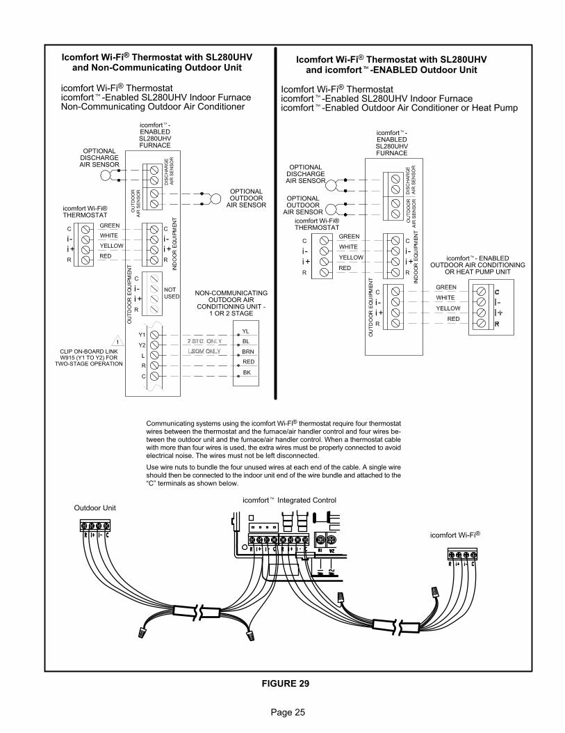
FIGURE 29
Icomfort Wi-Fi® Thermostat with SL280UHVand Non-Communicating Outdoor Unit
icomfort�-ENABLEDSL280UHVFURNACE
icomfort Wi-Fi®THERMOSTAT
NON-COMMUNICATINGOUTDOOR AIR
CONDITIONING UNIT -1 OR 2 STAGE
icomfort Wi-Fi® Thermostaticomfort�-Enabled SL280UHV Indoor FurnaceNon-Communicating Outdoor Air Conditioner
OPTIONALOUTDOOR
AIR SENSOR
OPTIONALDISCHARGEAIR SENSOR
Icomfort Wi-Fi® Thermostat with SL280UHVand icomfort�-ENABLED Outdoor Unit
Icomfort Wi-Fi® Thermostaticomfort�-Enabled SL280UHV Indoor Furnaceicomfort�-Enabled Outdoor Air Conditioner or Heat Pump
icomfort�-ENABLEDSL280UHVFURNACE
icomfort�- ENABLEDOUTDOOR AIR CONDITIONING
OR HEAT PUMP UNIT
OPTIONALOUTDOOR
AIR SENSOR
OPTIONALDISCHARGEAIR SENSOR
CLIP ON-BOARD LINKW915 (Y1 TO Y2) FOR
TWO-STAGE OPERATION
icomfort� Integrated Control
icomfort Wi-Fi®
Outdoor Unit
icomfort Wi-Fi®THERMOSTAT
Communicating systems using the icomfort Wi-Fi® thermostat require four thermostatwires between the thermostat and the furnace/air handler control and four wires between the outdoor unit and the furnace/air handler control. When a thermostat cablewith more than four wires is used, the extra wires must be properly connected to avoidelectrical noise. The wires must not be left disconnected.
Use wire nuts to bundle the four unused wires at each end of the cable. A single wireshould then be connected to the indoor unit end of the wire bundle and attached to the“C” terminals as shown below.
Page 26
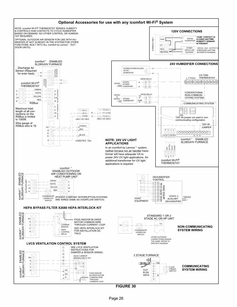
Optional Accessories for use with any icomfort Wi-Fi® System
FIGURE 30
NOTE: 24V UV LIGHTAPPLICATIONS
In an icomfort by Lennox� system,
neither furnace nor air handler trans
former will have adequate VA to
power 24V UV light applications. An
additional transformer for UV light
applications is required.
icomfort Wi-Fi®
THERMOSTAT
Discharge AirSensor (Required
for even heat)
NOTE: icomfort Wi-Fi® THERMOSTAT SENSES HUMIDITY& CONTROLS HUM CONTACTS TO CYCLE HUMIDIFIERBASED ON DEMAND. NO OTHER CONTROL OR HUMIDISTAT REQUIRED.
OPTIONAL OUTDOOR AIR SENSOR FOR USE WITH HUMIDIFIER (IF NOT ALREADY IN THE SYSTEM FOR OTHERFUNCTIONS. BUILT INTO ALL icomfort by Lennox� OUTDOOR UNITS).
Maximum totallength of all connections on theRSBus is limitedto 1500ft.
Wire gauge ofRSBus wire is 18.
RSBus
Rf
WG
hG
sC
fH
VA
C E
QU
IP
DEHUMIDIFIERCONTROL
HVACEQUIPMENT
DH
STANDARD 1 OR 2STAGE AC OR HP UNIT
*24V IN
JUMPER
icomfort� ENABLEDSL280UHV FURNACE
icomfort� ENABLEDSL280UHV FURNACE
icomfort Wi-Fi®
THERMOSTAT
CONVENTIONALNON-COMMUNICATING SYSTEM
COMMUNICATING SYSTEM
CS 7000THERMOSTAT
*24V IN jumper not used in non-communicating configuration
24V HUMIDIFIER CONNECTIONS
120V CONNECTIONS
HEPA BYPASS FILTER X2680 HEPA INTERLOCK KIT
PASS INDOOR BLOWERMOTOR COMMON WIRETHROUGH CURRENT LOOP.
SEE HEPA INTERLOCK KITFOR INSTALLATION DETAILS
icom
fort�
EN
AB
LE
DS
L280U
HV
FU
RN
AC
E
LVCS VENTILATION CONTROL SYSTEMSEE LVCS VENTILATIONINSTRUCTIONS FORDAMPER & SENSOR WIRING
icom
fort�
EN
AB
LE
DS
L280U
HV
FU
RN
AC
E
icomfort �ENABLED OUTDOOR
AIR CONDITIONING ORHEAT PUMP UNIT
(POWER COMPANY INTERRUPTION SYSTEMSARE WIRED SAME AS OVERFLOW SWITCH)ic
om
fort�
EN
AB
LE
DS
L280U
HV
FU
RN
AC
E
CUTR-DSW914
DS
R
2 STAGE FURNACE
COMMUNICATINGSYSTEM WIRING
NON-COMMUNICATINGSYSTEM WIRING
“HUM” CONTACT ISCLOSED ANYTIMEHUMIDITY DEMANDIS PRESENT
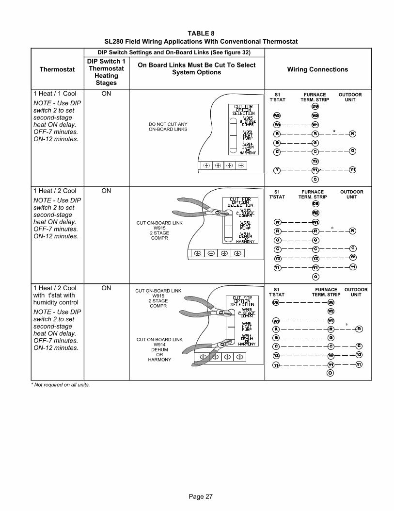
Page 27
TABLE 8
SL280 Field Wiring Applications With Conventional Thermostat
Thermostat
DIP Switch Settings and On-Board Links (See figure 32)
Wiring Connections
DIP Switch 1Thermostat
HeatingStages
On Board Links Must Be Cut To SelectSystem Options
1 Heat / 1 Cool
NOTE - Use DIPswitch 2 to setsecond-stageheat ON delay.OFF-7 minutes.ON-12 minutes.
ON
DO NOT CUT ANYON-BOARD LINKS
S1T'STAT
FURNACETERM. STRIP
OUTDOORUNIT
*
1 Heat / 2 Cool
NOTE - Use DIPswitch 2 to setsecond-stageheat ON delay.OFF-7 minutes.ON-12 minutes.
ON
CUT ON-BOARD LINKW915
2 STAGECOMPR
S1T'STAT
FURNACETERM. STRIP
OUTDOORUNIT
*
1 Heat / 2 Coolwith t'stat withhumidity control
NOTE - Use DIPswitch 2 to setsecond-stageheat ON delay.OFF-7 minutes.ON-12 minutes.
ONCUT ON-BOARD LINK
W9152 STAGECOMPR
CUT ON-BOARD LINKW914
DEHUMOR
HARMONY
S1T'STAT
FURNACETERM. STRIP
OUTDOORUNIT
o
*
* Not required on all units.
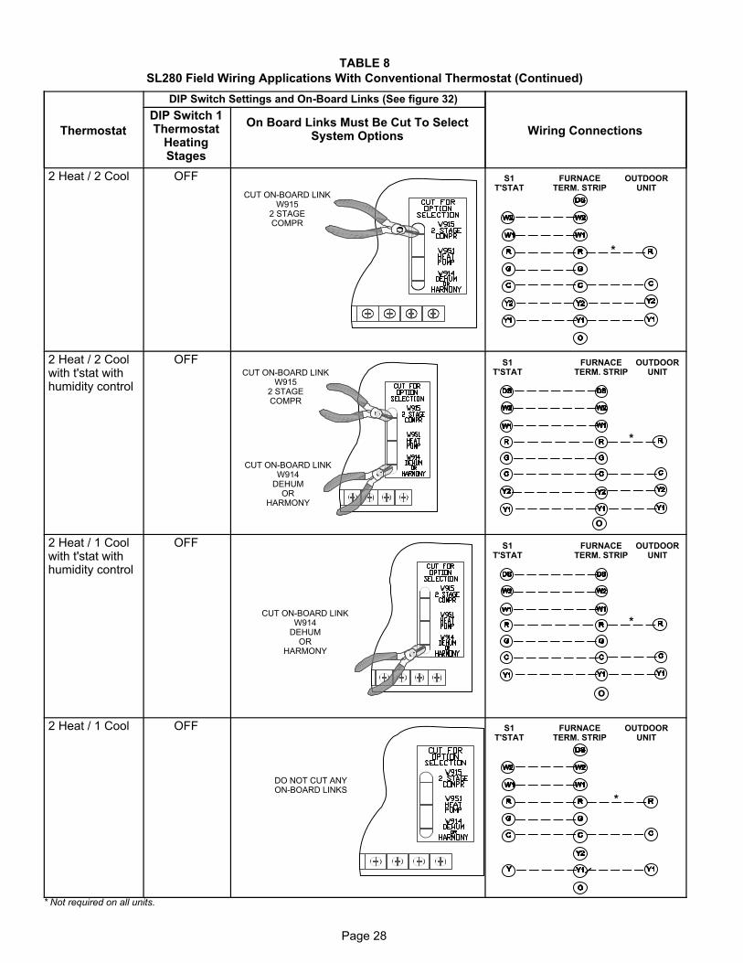
Page 28
TABLE 8
SL280 Field Wiring Applications With Conventional Thermostat (Continued)
Thermostat
DIP Switch Settings and On-Board Links (See figure 32)
Wiring Connections
DIP Switch 1Thermostat
HeatingStages
On Board Links Must Be Cut To SelectSystem Options
2 Heat / 2 Cool OFF
CUT ON-BOARD LINKW915
2 STAGECOMPR
S1T'STAT
FURNACETERM. STRIP
OUTDOORUNIT
*
2 Heat / 2 Coolwith t'stat withhumidity control
OFFCUT ON-BOARD LINK
W9152 STAGECOMPR
CUT ON-BOARD LINKW914
DEHUMOR
HARMONY
S1T'STAT
FURNACETERM. STRIP
OUTDOORUNIT
o
*
2 Heat / 1 Coolwith t'stat withhumidity control
OFF
CUT ON-BOARD LINKW914
DEHUMOR
HARMONY
S1T'STAT
FURNACETERM. STRIP
OUTDOORUNIT
o
*
2 Heat / 1 Cool OFF
DO NOT CUT ANYON-BOARD LINKS
S1T'STAT
FURNACETERM. STRIP
OUTDOORUNIT
*
* Not required on all units.
Page 29
TABLE 8
SL280 Field Wiring Applications With Conventional Thermostat (Continued)
Thermostat
DIP Switch Settings and On-Board Links (figure 32)
Wiring ConnectionsDIP Switch 1Thermostat
HeatingStages
On Board Links Must Be Cut To SelectSystem Options
Dual FuelSingle StageHeat Pump
ComfortSense7000 L7742Uthermostat w/dual fuel capabilitiesCapable of 2stage gas heatcontrol
OFF
CUT ON-BOARD LINKW951HEATPUMP
L7742UT'STAT
FURNACETERM. STRIP
HEAT PUMP
67M41*
Y
H
L
Y2
D
B
L
Y2
T
T
outdoorsensor
Dual FuelTwo StageHeat Pump
ComfortSense7000 L7742Uthermostat w/dual fuel capabilitiesCapable of 2stage gas heatcontrol
OFF
CUT ON-BOARD LINKW951HEATPUMP
CUT ON-BOARD LINKW915
2 STAGECOMPR
FURNACETERM. STRIP HEAT PUMP
out blue
67M41*
H
L
Y2
D
B
L
Y2
T
T
outdoorsensor
L7742UT'STAT
* Connect W1 to W1 ONLY if using defrost tempering kit 67M41
NOTE - Do NOT make a wire connection between the room thermostat L terminal and the L terminal of the SL280
integrated control.
Page 30
TABLE 8
SL280 Field Wiring Applications With Conventional Thermostat (Continued)
Thermostat
DIP Switch Settings and On-Board Links (figure 32)
Wiring ConnectionsDIP Switch 1Thermostat
HeatingStages
On Board Links Must Be Cut To SelectSystem Options
Dual FuelSingle StageHeat Pump
ComfortSense7000 L7742Uthermostat w/dual fuel capabilitiesCapable of 2stage gas heatcontrol w/dehumidificationcontrol
OFF
CUT ON-BOARD LINKW951HEATPUMP
CUT ON-BOARD LINKW914
DEHUMOR
HARMONY
L7742UT'STAT
FURNACETERM. STRIP
HEAT PUMP
67M41*
Y
H
L
Y2
D
B
L
Y2
T
T
outdoorsensor
Dual FuelTwo StageHeat Pump
ComfortSense7000 L7742Uthermostat w/dual fuel capabilitiesCapable of 2stage gas heatcontrol w/dehumidification
OFF
CUT ON-BOARD LINKW914
DEHUMOR
HARMONY
CUT ON-BOARD LINKW951HEATPUMP
CUT ON-BOARD LINKW915
2 STAGECOMPR
L7742UT'STAT
FURNACETERM. STRIP
HEAT PUMP
67M41*
H
L
Y2
D
B
L
Y2
T
T
outdoorsensor
Y2
out blue
* Connect W1 to W1 ONLY if using defrost tempering kit 67M41
NOTE - Do NOT make a wire connection between the room thermostat L terminal and the L terminal of the SL280
integrated control.
Page 31
SL280UHV Schematic Wiring Diagram
FIGURE 31
Page 32
Integrated Control
FIGURE 32
THERMOSTAT CONNECTIONS (TB1)
1/4” QUICK CONNECT TERMINALS
RS-BUS LINK (TB82, future use)
I+ = DATA HIGH CONNECTIONI - = DATA LOW CONNECTION
RS-BUS OUTDOOR (TB83)
R = 24VACI + = DATA HIGH CONNECTIONI - = DATA LOW CONNECTIONC = 24VAXC COMMON
RS-BUS INDOOR (TB84)
R = 24VACI + = DATA HIGH CONNECTIONI - = DATA LOW CONNECTIONC = 24VAXC COMMON
FLAME SENSE
DIP SWITCHES
OUTDOOR AIRSENSOR
TERMINALS
DISCHARGE AIRSENSOR
TERMINALS
INDOORBLOWER
CONNECTOR
NEUTRAL
DIAGNOSTICPUSH BUTTON
TB83COMMUNICATING
OUTDOOREQUIPMENT
TB84COMMUNICATING
INDOORTHERMOSTAT
DS = DEHUMIDIFICATION SIGNAL
W2 = HEAT DEMAND FROM 2ND STAGE T/STAT
W1 = HEAT DEMAND FROM 1ST STAGE T/STAT
R = CLASS 2 VOLTAGE TO THERMOSTAT
G = MANUAL FAN FROM T'STAT
C = THERMOSTAT SIGNAL GROUND CONNECTED TOTRANSFORMER GRD (TR) & CHASIS GROUND (GRD)
Y1 = THERMOSTAT 1ST STAGE COOL SIGNAL
Y2 = THERMOSTAT 2ND STAGE COOL SIGNAL
O = THERMOSTAT SIGNAL TO HEAT PUMPREVERSING VALVE
L = USE ONLY WITH A COMMUNICATING THERMOSTATAND A NON-COMMUNICATING OUTDOOR UNIT
DH = DEHUMIDIFICATION OUTPUT COMMUNICATINGTHERMOSTAT ONLY
HUM = UNPOWERED NORMALLY OPEN (DRY) CONTACTS
XMFR = 120 VAC OUTPUT TO TRANSFORMER
LI = 120 VAC INPUT TO CONTROL
ACC = 120 VAC OUTPUT TO OPTIONAL ACCESSORY
NEUTRALS = 120 VAC NEUTRAL
W915 Y1 TO Y22 STAGE COMPR
W951 R TO OHEAT PUMP
W914 R TO DSDEHUM ORHARMONYW1 W2 G Y2 Y1 C C R DH L O DSR I + I - C R I + I - C
7 SEGMENT LED
ACC
LINE 1
HUM
12 PIN LOWVOLTAGE
CONNECTOR
NON-COMMUNICATING24V TERMINALS
HS/ CAI
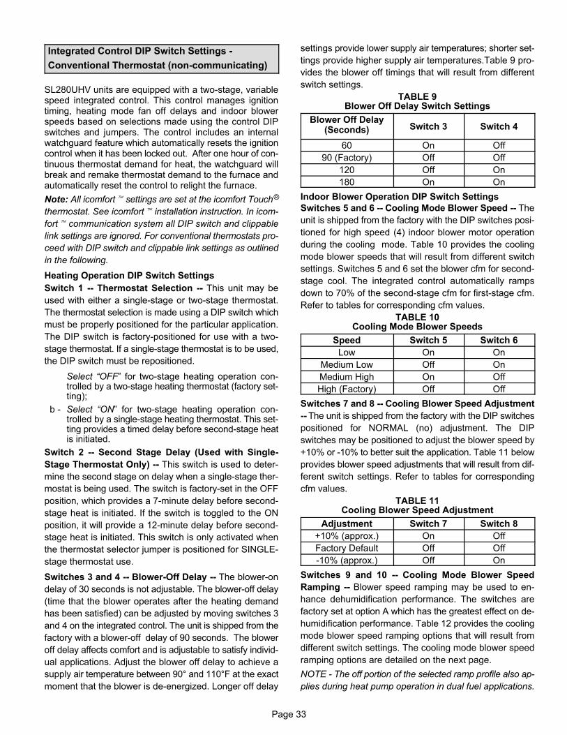
Page 33
Integrated Control DIP Switch Settings -
Conventional Thermostat (non-communicating)
SL280UHV units are equipped with a two-stage, variablespeed integrated control. This control manages ignitiontiming, heating mode fan off delays and indoor blowerspeeds based on selections made using the control DIPswitches and jumpers. The control includes an internalwatchguard feature which automatically resets the ignitioncontrol when it has been locked out. After one hour of continuous thermostat demand for heat, the watchguard willbreak and remake thermostat demand to the furnace andautomatically reset the control to relight the furnace.
Note: All icomfort� settings are set at the icomfort Touch®
thermostat. See icomfort� installation instruction. In icom
fort� communication system all DIP switch and clippable
link settings are ignored. For conventional thermostats pro
ceed with DIP switch and clippable link settings as outlined
in the following.
Heating Operation DIP Switch Settings
Switch 1 -- Thermostat Selection -- This unit may be
used with either a single-stage or two-stage thermostat.
The thermostat selection is made using a DIP switch which
must be properly positioned for the particular application.
The DIP switch is factory-positioned for use with a two-
stage thermostat. If a single-stage thermostat is to be used,
the DIP switch must be repositioned.
Select “OFF” for two-stage heating operation controlled by a two-stage heating thermostat (factory setting);
b - Select “ON” for two-stage heating operation controlled by a single-stage heating thermostat. This setting provides a timed delay before second-stage heatis initiated.
Switch 2 -- Second Stage Delay (Used with Single-
Stage Thermostat Only) -- This switch is used to deter
mine the second stage on delay when a single-stage ther
mostat is being used. The switch is factory-set in the OFF
position, which provides a 7-minute delay before second-
stage heat is initiated. If the switch is toggled to the ON
position, it will provide a 12-minute delay before second-
stage heat is initiated. This switch is only activated when
the thermostat selector jumper is positioned for SINGLE-
stage thermostat use.
Switches 3 and 4 -- Blower-Off Delay -- The blower-on
delay of 30 seconds is not adjustable. The blower-off delay
(time that the blower operates after the heating demand
has been satisfied) can be adjusted by moving switches 3
and 4 on the integrated control. The unit is shipped from the
factory with a blower-off delay of 90 seconds. The blower
off delay affects comfort and is adjustable to satisfy individ
ual applications. Adjust the blower off delay to achieve a
supply air temperature between 90° and 110°F at the exact
moment that the blower is de-energized. Longer off delay
settings provide lower supply air temperatures; shorter set
tings provide higher supply air temperatures.Table 9 pro
vides the blower off timings that will result from different
switch settings.
TABLE 9Blower Off Delay Switch Settings
Blower Off Delay(Seconds) Switch 3 Switch 4
60 On Off
90 (Factory) Off Off
120 Off On
180 On On
Indoor Blower Operation DIP Switch Settings
Switches 5 and 6 -- Cooling Mode Blower Speed -- The
unit is shipped from the factory with the DIP switches posi
tioned for high speed (4) indoor blower motor operation
during the cooling mode. Table 10 provides the cooling
mode blower speeds that will result from different switch
settings. Switches 5 and 6 set the blower cfm for second-
stage cool. The integrated control automatically ramps
down to 70% of the second-stage cfm for first-stage cfm.
Refer to tables for corresponding cfm values.
TABLE 10Cooling Mode Blower Speeds
Speed Switch 5 Switch 6
Low On On
Medium Low Off On
Medium High On Off
High (Factory) Off Off
Switches 7 and 8 -- Cooling Blower Speed Adjustment
-- The unit is shipped from the factory with the DIP switches
positioned for NORMAL (no) adjustment. The DIP
switches may be positioned to adjust the blower speed by
+10% or -10% to better suit the application. Table 11 below
provides blower speed adjustments that will result from dif
ferent switch settings. Refer to tables for corresponding
cfm values.
TABLE 11Cooling Blower Speed Adjustment
Adjustment Switch 7 Switch 8
+10% (approx.) On Off
Factory Default Off Off
-10% (approx.) Off On
Switches 9 and 10 -- Cooling Mode Blower Speed
Ramping -- Blower speed ramping may be used to en
hance dehumidification performance. The switches are
factory set at option A which has the greatest effect on de-
humidification performance. Table 12 provides the cooling
mode blower speed ramping options that will result from
different switch settings. The cooling mode blower speed
ramping options are detailed on the next page.
NOTE - The off portion of the selected ramp profile also ap
plies during heat pump operation in dual fuel applications.
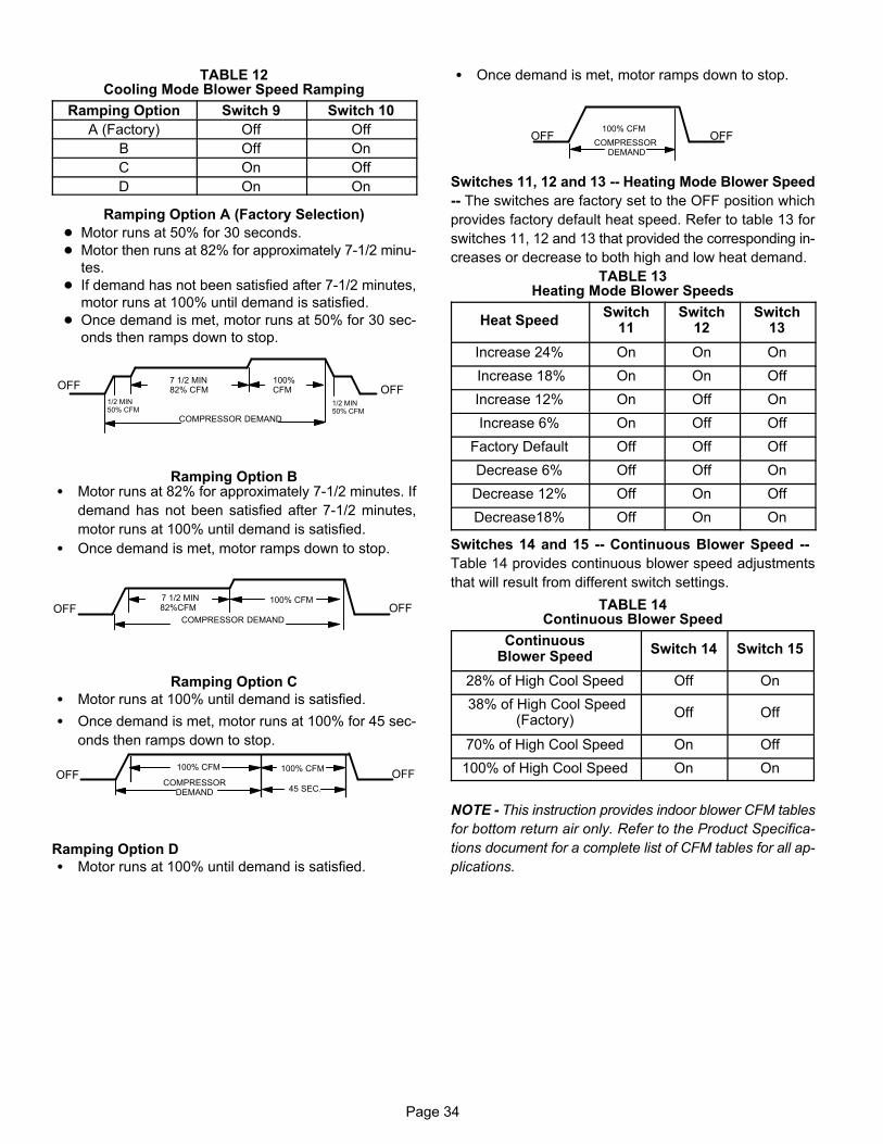
Page 34
TABLE 12Cooling Mode Blower Speed Ramping
Ramping Option Switch 9 Switch 10
A (Factory) Off Off
B Off On
C On Off
D On On
Ramping Option A (Factory Selection)
� Motor runs at 50% for 30 seconds.
� Motor then runs at 82% for approximately 7-1/2 minu
tes.
� If demand has not been satisfied after 7-1/2 minutes,
motor runs at 100% until demand is satisfied.
� Once demand is met, motor runs at 50% for 30 sec
onds then ramps down to stop.
OFFOFF
1/2 MIN50% CFM
COMPRESSOR DEMAND
7 1/2 MIN82% CFM
100% CFM
1/2 MIN50% CFM
Ramping Option B� Motor runs at 82% for approximately 7-1/2 minutes. If
demand has not been satisfied after 7-1/2 minutes,
motor runs at 100% until demand is satisfied.
� Once demand is met, motor ramps down to stop.
OFFOFF 82%CFM100% CFM
COMPRESSOR DEMAND
7 1/2 MIN
Ramping Option C
� Motor runs at 100% until demand is satisfied.
� Once demand is met, motor runs at 100% for 45 sec
onds then ramps down to stop.
OFFOFF100% CFM 100% CFM
45 SEC.COMPRESSOR
DEMAND
Ramping Option D
� Motor runs at 100% until demand is satisfied.
� Once demand is met, motor ramps down to stop.
OFFOFF100% CFM
COMPRESSOR DEMAND
Switches 11, 12 and 13 -- Heating Mode Blower Speed
-- The switches are factory set to the OFF position which
provides factory default heat speed. Refer to table 13 for
switches 11, 12 and 13 that provided the corresponding in
creases or decrease to both high and low heat demand.
TABLE 13Heating Mode Blower Speeds
Heat SpeedSwitch
11Switch
12Switch
13
Increase 24% On On On
Increase 18% On On Off
Increase 12% On Off On
Increase 6% On Off Off
Factory Default Off Off Off
Decrease 6% Off Off On
Decrease 12% Off On Off
Decrease18% Off On On
Switches 14 and 15 -- Continuous Blower Speed --
Table 14 provides continuous blower speed adjustments
that will result from different switch settings.
TABLE 14Continuous Blower Speed
ContinuousBlower Speed
Switch 14 Switch 15
28% of High Cool Speed Off On
38% of High Cool Speed(Factory)
Off Off
70% of High Cool Speed On Off
100% of High Cool Speed On On
NOTE - This instruction provides indoor blower CFM tables
for bottom return air only. Refer to the Product Specifica
tions document for a complete list of CFM tables for all ap
plications.
Page 35
On-Board Links
Note: In icomfort� systems with a conventional outdoor
unit (non-communicating), the on-board clippable links
must be set to properly configure the system.
WARNINGCarefully review all configuration information provided. Failure to properly set DIP switches, jumpersand on-board links can result in improper operation!
On-Board Link W914 Dehum or Harmony (R to DS)
On-board link W914, is a clippable connection between terminals R and DS on the integrated control. W914 must becut when the furnace is installed with either the HarmonyIII� zone control or a thermostat which features humiditycontrol. If the link is left intact the PMW signal from the Harmony III control will be blocked and also lead to controldamage. Refer to table 15 for operation sequence in applications including SL280UHV, a thermostat which features humidity control and a single-speed outdoor unit.Table 16 gives the operation sequence in applications witha two-speed outdoor unit.
On-Board Link W951 Heat Pump (R to O)
On-board link W951 is a clippable connection between terminals R and O on the integrated control. W951 must be cutwhen the furnace is installed in applications which include aheat pump unit and a thermostat which features dual fueluse. If the link is left intact, terminal “O” will remain energized eliminating the HEAT MODE in the heat pump.
On-Board Link W915 2 Stage Compr (Y1 to Y2)On-board link W915 is a clippable connection between terminals Y1 and Y2 on the integrated control. W915 must becut if two-stage cooling will be used. If the Y1 to Y2 link isnot cut the outdoor unit will operate in second-stage cooling only.
Diagnostic LED (Figure 32)The seven-segment diagnostic LED displays operatingstatus, target airflow, error codes and other information.The table beginning on Page 49 lists diagnostic LEDcodes.
Diagnostic Push Button (Figure 32)The diagnostic push button is located adjacent to theseven-segment diagnostic LED. This button is used to enable the Error Code Recall “E” mode and the Flame Signal“F” mode. Press the button and hold it to cycle through amenu of options. Every five seconds a new menu item willbe displayed. When the button is released, the displayeditem will be selected. Once all items in the menu have beendisplayed, the menu resumes from the beginning until thebutton is released.
Error Code Recall ModeSelect ”E” from the menu to access the most recent 10 errorcodes. Select “c” from the Error Code Recall menu to clearall error codes. Button must be pressed a second timewhile “c” is flashing to confirm command to delete codes.Press the button until a solid “≡” is displayed to exit the ErrorCode Recall mode.
Flame Signal ModeSelect ”F” from the menu to access the flame signal mode.The integrated control will display the flame current on 7segment LED in in micro amps (uA).
Flame signal mode is exited after the following:
� Power is reset � Pressing and holding push button until 3 horizontal
lines “≡” are displayed
� 10 minutes of entering the flame sense mode.
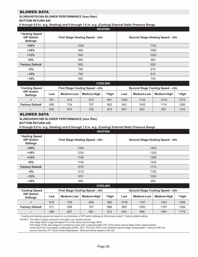
Page 36
BLOWER DATASL280UH070V36A BLOWER PERFORMANCE (less filter)BOTTOM RETURN AIR0 through 0.8 in. w.g. (Heating) and 0 through 1.0 in. w.g. (Cooling) External Static Pressure Range
HEATING1 Heating Speed
DIP Switch Settings
First Stage Heating Speed - cfm Second Stage Heating Speed - cfm
+24% 1045 1145+18% 985 1080+12% 940 1035+6% 880 960
Factory Default 850 925–6% 785 875
–12% 745 815–18% 680 745
COOLING1 Cooling Speed
DIP Switch Settings
First Stage Cooling Speed - cfm Second Stage Cooling Speed - cfm
Low Medium-Low Medium-High 2 High Low Medium-Low Medium-High 2 High
+ 781 819 872 981 1045 1139 1219 1372Factory Default 695 734 797 883 943 1005 1114 1260
– 645 674 720 815 847 922 991 1144
BLOWER DATASL280UH090V36B BLOWER PERFORMANCE (less filter)BOTTOM RETURN AIR0 through 0.8 in. w.g. (Heating) and 0 through 1.0 in. w.g. (Cooling) External Static Pressure Range
HEATING1 Heating Speed
DIP Switch Settings
First Stage Heating Speed - cfm Second Stage Heating Speed - cfm
+24% 1300 1420+18% 1250 1335+12% 1185 1285+6% 1145 1240
Factory Default 1070 1170–6% 1015 1100–12% 970 1035–18% 880 980
COOLING1 Cooling Speed
DIP Switch Settings
First Stage Cooling Speed - cfm Second Stage Cooling Speed - cfm
Low Medium-Low Medium-High 2 High Low Medium-Low Medium-High 2 High
+ 616 755 846 980 1018 1197 1291 1399Factory Default 571 698 767 886 909 1083 1197 1284
– 489 627 681 812 834 968 1081 11791 Cooling and heating speeds are based on a combination of DIP switch settings on the furnace control.2 Factory default setting.NOTES - The effect of static pressure is included in air volumes shown.
First stage HEAT is approximately 91% of the same second stage HEAT. First stage COOL (two-stage air conditioning units only) is approximately 70% of the same second stage COOL speed position. Continuous Fan Only speed is selectable at 28%, 38%, 70% and 100% of the selected second stage cooling speed - minimum 250 cfm. Lennox Harmony III™ Zone Control Applications - Minimum blower speed is 250 cfm
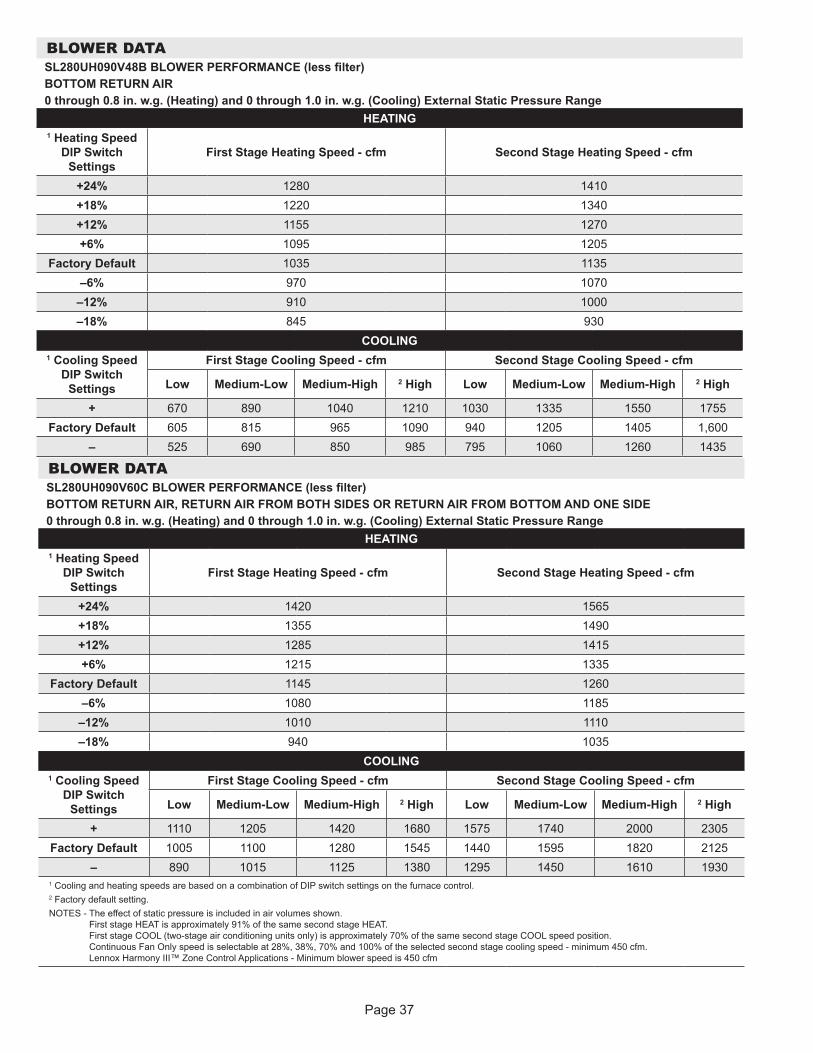
Page 37
BLOWER DATASL280UH090V48B BLOWER PERFORMANCE (less filter)BOTTOM RETURN AIR0 through 0.8 in. w.g. (Heating) and 0 through 1.0 in. w.g. (Cooling) External Static Pressure Range
HEATING1 Heating Speed
DIP Switch Settings
First Stage Heating Speed - cfm Second Stage Heating Speed - cfm
+24% 1280 1410+18% 1220 1340+12% 1155 1270+6% 1095 1205
Factory Default 1035 1135–6% 970 1070
–12% 910 1000–18% 845 930
COOLING1 Cooling Speed
DIP Switch Settings
First Stage Cooling Speed - cfm Second Stage Cooling Speed - cfm
Low Medium-Low Medium-High 2 High Low Medium-Low Medium-High 2 High
+ 670 890 1040 1210 1030 1335 1550 1755Factory Default 605 815 965 1090 940 1205 1405 1,600
– 525 690 850 985 795 1060 1260 1435
BLOWER DATASL280UH090V60C BLOWER PERFORMANCE (less filter)BOTTOM RETURN AIR, RETURN AIR FROM BOTH SIDES OR RETURN AIR FROM BOTTOM AND ONE SIDE0 through 0.8 in. w.g. (Heating) and 0 through 1.0 in. w.g. (Cooling) External Static Pressure Range
HEATING1 Heating Speed
DIP Switch Settings
First Stage Heating Speed - cfm Second Stage Heating Speed - cfm
+24% 1420 1565+18% 1355 1490+12% 1285 1415+6% 1215 1335
Factory Default 1145 1260–6% 1080 1185–12% 1010 1110–18% 940 1035
COOLING1 Cooling Speed
DIP Switch Settings
First Stage Cooling Speed - cfm Second Stage Cooling Speed - cfm
Low Medium-Low Medium-High 2 High Low Medium-Low Medium-High 2 High
+ 1110 1205 1420 1680 1575 1740 2000 2305Factory Default 1005 1100 1280 1545 1440 1595 1820 2125
– 890 1015 1125 1380 1295 1450 1610 19301 Cooling and heating speeds are based on a combination of DIP switch settings on the furnace control.2 Factory default setting.NOTES - The effect of static pressure is included in air volumes shown.
First stage HEAT is approximately 91% of the same second stage HEAT. First stage COOL (two-stage air conditioning units only) is approximately 70% of the same second stage COOL speed position. Continuous Fan Only speed is selectable at 28%, 38%, 70% and 100% of the selected second stage cooling speed - minimum 450 cfm. Lennox Harmony III™ Zone Control Applications - Minimum blower speed is 450 cfm
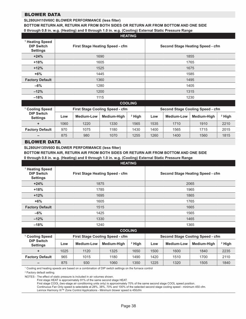
Page 38
BLOWER DATASL280UH110V60C BLOWER PERFORMANCE (less filter)BOTTOM RETURN AIR, RETURN AIR FROM BOTH SIDES OR RETURN AIR FROM BOTTOM AND ONE SIDE0 through 0.8 in. w.g. (Heating) and 0 through 1.0 in. w.g. (Cooling) External Static Pressure Range
HEATING1 Heating Speed
DIP Switch Settings
First Stage Heating Speed - cfm Second Stage Heating Speed - cfm
+24% 1690 1855+18% 1605 1765+12% 1525 1675+6% 1445 1585
Factory Default 1360 1495–6% 1280 1405
–12% 1200 1315–18% 1115 1230
COOLING1 Cooling Speed
DIP Switch Settings
First Stage Cooling Speed - cfm Second Stage Cooling Speed - cfm
Low Medium-Low Medium-High 2 High Low Medium-Low Medium-High 2 High
+ 1060 1220 1330 1565 1535 1710 1910 2210Factory Default 970 1075 1180 1430 1400 1565 1715 2015
– 875 980 1070 1255 1260 1400 1560 1815
BLOWER DATASL280UH135V60D BLOWER PERFORMANCE (less filter)BOTTOM RETURN AIR, RETURN AIR FROM BOTH SIDES OR RETURN AIR FROM BOTTOM AND ONE SIDE0 through 0.8 in. w.g. (Heating) and 0 through 1.0 in. w.g. (Cooling) External Static Pressure Range
HEATING1 Heating Speed
DIP Switch Settings
First Stage Heating Speed - cfm Second Stage Heating Speed - cfm
+24% 1875 2065+18% 1785 1965+12% 1695 1865+6% 1605 1765
Factory Default 1515 1665–6% 1425 1565
–12% 1330 1465–18% 1240 1365
COOLING1 Cooling Speed
DIP Switch Settings
First Stage Cooling Speed - cfm Second Stage Cooling Speed - cfm
Low Medium-Low Medium-High 2 High Low Medium-Low Medium-High 2 High
+ 1025 1120 1325 1650 1500 1600 1840 2235Factory Default 965 1015 1180 1490 1420 1510 1700 2110
– 875 930 1060 1350 1225 1320 1505 18401 Cooling and heating speeds are based on a combination of DIP switch settings on the furnace control2 Factory default setting.NOTES - The effect of static pressure is included in air volumes shown.
First stage HEAT is approximately 91% of the same second stage HEAT. First stage COOL (two-stage air conditioning units only) is approximately 70% of the same second stage COOL speed position. Continuous Fan Only speed is selectable at 28%, 38%, 70% and 100% of the selected second stage cooling speed - minimum 450 cfm. Lennox Harmony III™ Zone Control Applications - Minimum blower speed is 450cfm
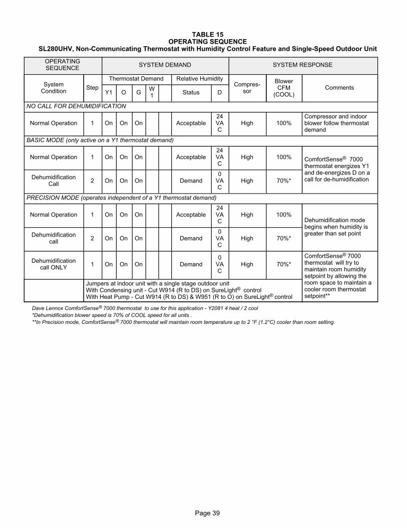
Page 39
TABLE 15OPERATING SEQUENCE
SL280UHV, Non-Communicating Thermostat with Humidity Control Feature and Single-Speed Outdoor Unit
OPERATINGSEQUENCE
SYSTEM DEMAND SYSTEM RESPONSE
SystemCondition
Step
Thermostat Demand Relative HumidityCompres
sor
BlowerCFM
(COOL)Comments
Y1 O GW1
Status D
NO CALL FOR DEHUMIDIFICATION
Normal Operation 1 On On On Acceptable24VAC
High 100%Compressor and indoorblower follow thermostatdemand
BASIC MODE (only active on a Y1 thermostat demand)
Normal Operation 1 On On On Acceptable24VAC
High 100% ComfortSense® 7000thermostat energizes Y1and de-energizes D on acall for de-humidificationDehumidification
Call2 On On On Demand
0VAC
High 70%*
PRECISION MODE (operates independent of a Y1 thermostat demand)
Normal Operation 1 On On On Acceptable24VAC
High 100%Dehumidification modebegins when humidity isgreater than set pointDehumidification
call2 On On On Demand
0VAC
High 70%*
Dehumidificationcall ONLY
1 On On On Demand0
VAC
High 70%*
ComfortSense® 7000thermostat will try tomaintain room humiditysetpoint by allowing theroom space to maintain acooler room thermostatsetpoint**
Jumpers at indoor unit with a single stage outdoor unitWith Condensing unit - Cut W914 (R to DS) on SureLight® controlWith Heat Pump - Cut W914 (R to DS) & W951 (R to O) on SureLight® control
Dave Lennox ComfortSense® 7000 thermostat to use for this application - Y2081 4 heat / 2 cool
*Dehumidification blower speed is 70% of COOL speed for all units .
**In Precision mode, ComfortSense® 7000 thermostat will maintain room temperature up to 2 °F (1.2°C) cooler than room setting.
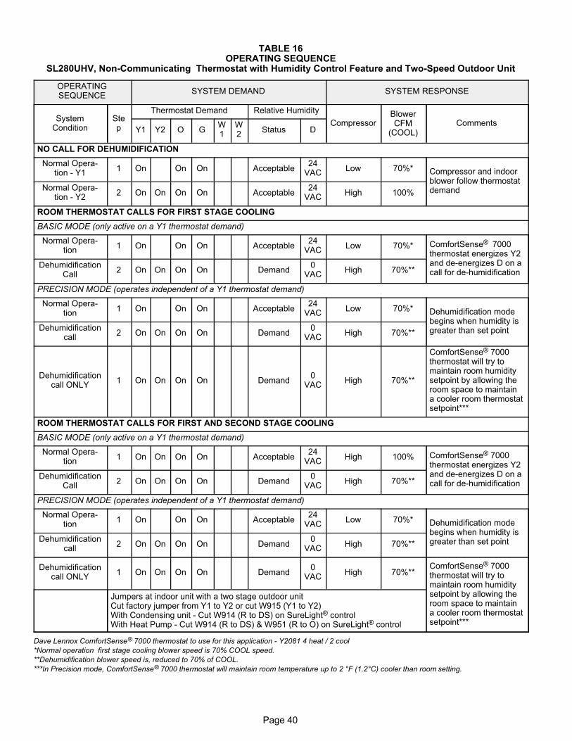
Page 40
TABLE 16OPERATING SEQUENCE
SL280UHV, Non-Communicating Thermostat with Humidity Control Feature and Two-Speed Outdoor Unit
OPERATINGSEQUENCE
SYSTEM DEMAND SYSTEM RESPONSE
SystemCondition
Step
Thermostat Demand Relative Humidity
CompressorBlowerCFM
(COOL)Comments
Y1 Y2 O GW1
W2
Status D
NO CALL FOR DEHUMIDIFICATION
Normal Operation - Y1
1 On On On Acceptable24
VACLow 70%* Compressor and indoor
blower follow thermostatdemandNormal Opera
tion - Y22 On On On On Acceptable
24VAC
High 100%
ROOM THERMOSTAT CALLS FOR FIRST STAGE COOLING
BASIC MODE (only active on a Y1 thermostat demand)
Normal Operation
1 On On On Acceptable24
VACLow 70%* ComfortSense® 7000
thermostat energizes Y2and de-energizes D on acall for de-humidification
DehumidificationCall
2 On On On On Demand0
VACHigh 70%**
PRECISION MODE (operates independent of a Y1 thermostat demand)
Normal Operation
1 On On On Acceptable24
VACLow 70%* Dehumidification mode
begins when humidity isgreater than set pointDehumidification
call2 On On On On Demand
0VAC
High 70%**
Dehumidificationcall ONLY
1 On On On On Demand0
VACHigh 70%**
ComfortSense® 7000thermostat will try tomaintain room humiditysetpoint by allowing theroom space to maintaina cooler room thermostatsetpoint***
ROOM THERMOSTAT CALLS FOR FIRST AND SECOND STAGE COOLING
BASIC MODE (only active on a Y1 thermostat demand)
Normal Operation
1 On On On On Acceptable24
VACHigh 100% ComfortSense® 7000
thermostat energizes Y2and de-energizes D on acall for de-humidification
DehumidificationCall
2 On On On On Demand0
VACHigh 70%**
PRECISION MODE (operates independent of a Y1 thermostat demand)
Normal Operation
1 On On On Acceptable24
VACLow 70%* Dehumidification mode
begins when humidity isgreater than set pointDehumidification
call2 On On On On Demand
0VAC
High 70%**
Dehumidificationcall ONLY
1 On On On On Demand0
VACHigh 70%**
ComfortSense® 7000thermostat will try tomaintain room humiditysetpoint by allowing theroom space to maintaina cooler room thermostatsetpoint***
Jumpers at indoor unit with a two stage outdoor unitCut factory jumper from Y1 to Y2 or cut W915 (Y1 to Y2)With Condensing unit - Cut W914 (R to DS) on SureLight® controlWith Heat Pump - Cut W914 (R to DS) & W951 (R to O) on SureLight® control
Dave Lennox ComfortSense® 7000 thermostat to use for this application - Y2081 4 heat / 2 cool
*Normal operation first stage cooling blower speed is 70% COOL speed.
**Dehumidification blower speed is, reduced to 70% of COOL.
***In Precision mode, ComfortSense® 7000 thermostat will maintain room temperature up to 2 °F (1.2°C) cooler than room setting.
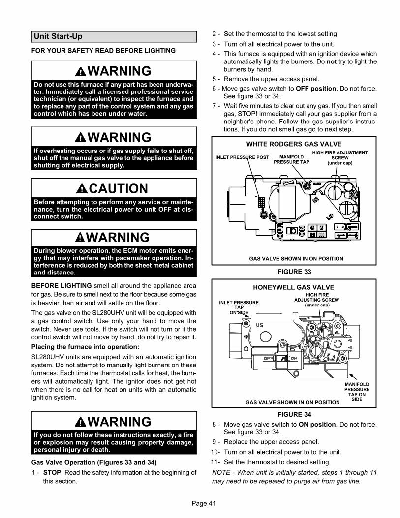
Page 41
Unit Start-Up
FOR YOUR SAFETY READ BEFORE LIGHTING
WARNINGDo not use this furnace if any part has been underwater. Immediately call a licensed professional servicetechnician (or equivalent) to inspect the furnace andto replace any part of the control system and any gascontrol which has been under water.
WARNINGIf overheating occurs or if gas supply fails to shut off,shut off the manual gas valve to the appliance beforeshutting off electrical supply.
CAUTIONBefore attempting to perform any service or maintenance, turn the electrical power to unit OFF at disconnect switch.
WARNINGDuring blower operation, the ECM motor emits energy that may interfere with pacemaker operation. Interference is reduced by both the sheet metal cabinetand distance.
BEFORE LIGHTING smell all around the appliance area
for gas. Be sure to smell next to the floor because some gas
is heavier than air and will settle on the floor.
The gas valve on the SL280UHV unit will be equipped with
a gas control switch. Use only your hand to move the
switch. Never use tools. If the switch will not turn or if the
control switch will not move by hand, do not try to repair it.
Placing the furnace into operation:
SL280UHV units are equipped with an automatic ignition
system. Do not attempt to manually light burners on these
furnaces. Each time the thermostat calls for heat, the burn
ers will automatically light. The ignitor does not get hot
when there is no call for heat on units with an automatic
ignition system.
WARNINGIf you do not follow these instructions exactly, a fireor explosion may result causing property damage,personal injury or death.
Gas Valve Operation (Figures 33 and 34)
1 - STOP! Read the safety information at the beginning of
this section.
2 - Set the thermostat to the lowest setting.
3 - Turn off all electrical power to the unit.
4 - This furnace is equipped with an ignition device which
automatically lights the burners. Do not try to light the
burners by hand.
5 - Remove the upper access panel.
6 - Move gas valve switch to OFF position. Do not force.
See figure 33 or 34.
7 - Wait five minutes to clear out any gas. If you then smell
gas, STOP! Immediately call your gas supplier from a
neighbor's phone. Follow the gas supplier's instruc
tions. If you do not smell gas go to next step.
GAS VALVE SHOWN IN ON POSITION
INLET PRESSURE POSTHIGH FIRE ADJUSTMENT
SCREW(under cap)
MANIFOLDPRESSURE TAP
WHITE RODGERS GAS VALVE
FIGURE 33
GAS VALVE SHOWN IN ON POSITION
MANIFOLDPRESSURE
TAP ONSIDE
HIGH FIREADJUSTING SCREW
(under cap)INLET PRESSURE
TAPON SIDE
HONEYWELL GAS VALVE
FIGURE 34
8 - Move gas valve switch to ON position. Do not force.
See figure 33 or 34.
9 - Replace the upper access panel.
10- Turn on all electrical power to to the unit.
11- Set the thermostat to desired setting.
NOTE - When unit is initially started, steps 1 through 11
may need to be repeated to purge air from gas line.
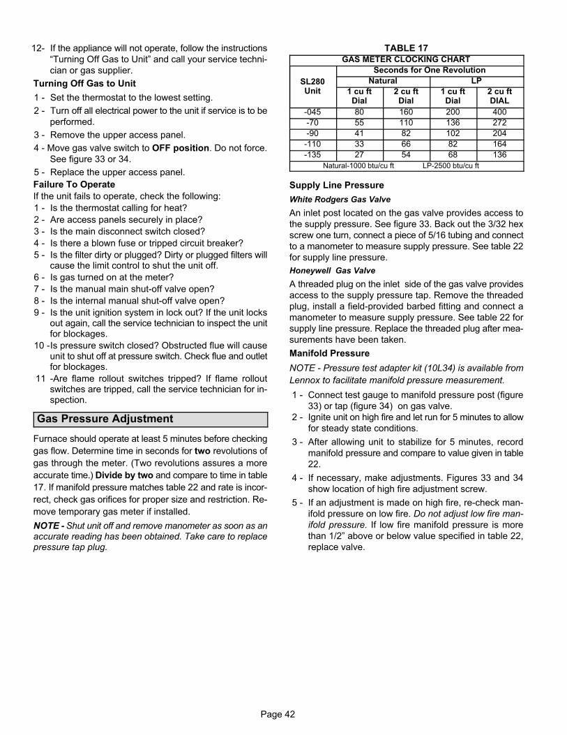
Page 42
12- If the appliance will not operate, follow the instructions
“Turning Off Gas to Unit” and call your service techni
cian or gas supplier.
Turning Off Gas to Unit
1 - Set the thermostat to the lowest setting.
2 - Turn off all electrical power to the unit if service is to be
performed.
3 - Remove the upper access panel.
4 - Move gas valve switch to OFF position. Do not force.
See figure 33 or 34.
5 - Replace the upper access panel.
Failure To Operate
If the unit fails to operate, check the following:
1 - Is the thermostat calling for heat?
2 - Are access panels securely in place?
3 - Is the main disconnect switch closed?
4 - Is there a blown fuse or tripped circuit breaker?
5 - Is the filter dirty or plugged? Dirty or plugged filters willcause the limit control to shut the unit off.
6 - Is gas turned on at the meter?
7 - Is the manual main shut‐off valve open?
8 - Is the internal manual shut‐off valve open?
9 - Is the unit ignition system in lock out? If the unit locksout again, call the service technician to inspect the unitfor blockages.
10 -Is pressure switch closed? Obstructed flue will causeunit to shut off at pressure switch. Check flue and outletfor blockages.
11 -Are flame rollout switches tripped? If flame rolloutswitches are tripped, call the service technician for inspection.
Gas Pressure Adjustment
Furnace should operate at least 5 minutes before checking
gas flow. Determine time in seconds for two revolutions of
gas through the meter. (Two revolutions assures a more
accurate time.) Divide by two and compare to time in table
17. If manifold pressure matches table 22 and rate is incor
rect, check gas orifices for proper size and restriction. Re
move temporary gas meter if installed.
NOTE - Shut unit off and remove manometer as soon as anaccurate reading has been obtained. Take care to replacepressure tap plug.
TABLE 17GAS METER CLOCKING CHART
SL280Unit
Seconds for One Revolution
Natural LP
1 cu ftDial
2 cu ftDial
1 cu ftDial
2 cu ftDIAL
-045 80 160 200 400
-70 55 110 136 272
-90 41 82 102 204
-110 33 66 82 164
-135 27 54 68 136
Natural-1000 btu/cu ft LP-2500 btu/cu ft
Supply Line Pressure
White Rodgers Gas Valve
An inlet post located on the gas valve provides access to
the supply pressure. See figure 33. Back out the 3/32 hex
screw one turn, connect a piece of 5/16 tubing and connect
to a manometer to measure supply pressure. See table 22
for supply line pressure.
Honeywell Gas Valve
A threaded plug on the inlet side of the gas valve provides
access to the supply pressure tap. Remove the threaded
plug, install a field-provided barbed fitting and connect a
manometer to measure supply pressure. See table 22 for
supply line pressure. Replace the threaded plug after mea
surements have been taken.
Manifold Pressure
NOTE - Pressure test adapter kit (10L34) is available from
Lennox to facilitate manifold pressure measurement.
1 - Connect test gauge to manifold pressure post (figure
33) or tap (figure 34) on gas valve.
2 - Ignite unit on high fire and let run for 5 minutes to allow
for steady state conditions.
3 - After allowing unit to stabilize for 5 minutes, record
manifold pressure and compare to value given in table
22.
4 - If necessary, make adjustments. Figures 33 and 34
show location of high fire adjustment screw.
5 - If an adjustment is made on high fire, re-check man
ifold pressure on low fire. Do not adjust low fire man
ifold pressure. If low fire manifold pressure is more
than 1/2” above or below value specified in table 22,
replace valve.
Page 43
Proper Combustion
Furnace should operate minimum 15 minutes with correct
manifold pressure and gas flow rate before checking com
bustion. Table 18 shows acceptable combustion carbon di
oxide rates for ALL SL280UHV models. The maximum car
bon monoxide reading should not exceed 50 ppm.
TABLE 18
Firing Rate CO2% For Nat CO2% For L.P.
High Fire 6.8 - 7.4 7.5 - 9.0
Low Fire 4.2 - 5.7 5.0 - 6.0
High Altitude
The manifold pressure, gas orifice and pressure switch
may require adjustment or replacement to ensure proper
operation at higher altitudes. Tables 19 through 22 show
manifold pressures, pressure switches and gas conversion
kits at all altitudes.
IMPORTANTFor safety, shut unit off and remove manometer assoon as an accurate reading has been obtained.Take care to replace pressure tap plug.
TABLE 19
High Altitude Pressure Switch Kits
UnitInput
0 - 4500 ft. 4501 - 7500 ft. 7501 - 10,000 ft.
070 No Change No Change 73W35
090 No Change 69W56 73W35
110 No Change 69W56 73W35
135 No Change 73W33 73W34
TABLE 20
Honeywell Gas Valve Conversion Kits
UnitInput
High AltitudeNatural GasOrifice Kit
Natural Gas toLP/ Propane Kit
LP/Propaneto
Natural GasKit
7501 -10,000 ft.
0 - 7500 ft.7501 -
10,000 ft.0 - 7500 ft.
070 73W37 51W02 73W38 69W79
090 73W37 51W02 73W38 69W79
110 73W37 51W02 73W38 69W79
135 73W37 51W02 73W38 69W79
TABLE 21
White Rodgers Gas Valve Conversion Kits
UnitInput
High AltitudeNatural GasOrifice Kit
Natural Gas toLP/ Propane Kit
LP/Propaneto
Natural GasKit
7501 -10,000 ft.
0 - 7500 ft.7501 -
10,000 ft.0 - 7500 ft.
070 73W37 77W07 77W11 77W09
090 73W37 77W07 77W11 77W09
110 73W37 77W07 77W11 77W09
135 73W37 77W07 77W11 77W09
TABLE 22
Manifold Pressure Settings
UnitInput
GasOrifice Size0 - 7500 ft.
Orifice Size7501 -
10,000 ft.1
ManifoldPressure in.wg.
0-4500 ft.
ManifoldPressure in.wg.
4501-7500 ft.
ManifoldPressure in.wg.7501 - 10,000 ft.2
Supply LinePressurein. w.g.
LowFire
HighFire
LowFire
HighFire
LowFire
HighFire
Min Max
070Natural .063 .055 1.7 3.5 1.6 3.4 1.7 3.5 4.5 13.0
LP/propane3 .039 .037 4.9 10.0 4.9 10.0 4.9 10.0 11.0 13.0
090Natural .063 .055 1.7 3.5 1.5 3.2 1.7 3.5 4.5 13.0
LP/propane3 .039 .037 4.9 10.0 4.9 10.0 4.9 10.0 11.0 13.0
110Natural .063 .055 1.7 3.5 1.5 3.2 1.7 3.5 4.5 13.0
LP/propane3 .039 .037 4.9 10.0 4.9 10.0 4.9 10.0 11.0 13.0
135Natural .063 .055 1.7 3.5 1.6 2.8 1.7 3.5 4.5 13.0
LP/propane3 .039 .037 4.9 10.0 4.9 10.0 4.9 10.0 11.0 13.0
1 This is the only permissible derate for these units.
2 Natural gas high altitude orifice kit required.
3 A natural to L.P. propane gas changeover kit is necessary to convert this unit. Refer to the changeover kit installation instruction for the conversion
procedure.
NOTE - Units may be installed at altitudes up to 4500 ft. above sea level without modifications.
Page 44
Other Unit Adjustments
Primary and Secondary Limits
The primary limit is located on the heating compartment
vestibule panel. The secondary limits (if equipped) are lo
cated in the blower compartment, attached to the back side
of the blower. These auto reset limits are factory set and re
quire no adjustment.
Flame Rollout Switches (Two)
These manually reset switches are located on (or inside of)
the burner box. If tripped, check for adequate combustion
air before resetting.
Pressure Switches
The pressure switch assembly (includes two switches) is
located in the heating compartment adjacent to the com
bustion air inducer. These switches check for proper com
bustion air inducer operation before allowing ignition trial.
The switches are factory-set and require no adjustment.
Temperature Rise
Place the unit into operation with a second-stage heating
demand. After supply and return air temperatures have
stabilized, check the temperature rise. If necessary, adjust
the heating blower speed to maintain the temperature rise
within the range shown on the unit nameplate. Increase the
blower speed to decrease the temperature rise. Decrease
the blower speed to increase the temperature rise. Failure
to properly adjust the temperature rise may cause erratic
limit operation.
Thermostat Heat Anticipation
Set the heat anticipator setting (if adjustable) according to
the amp draw listed on the wiring diagram that is attached
to the unit.
NOTE - Do not secure the electrical conduit directly to theair ducts or structure.
Heating Sequence of Operation
Electronic Ignition
The two-stage, variable speed integrated control used inSL280UHV units has an added feature of an internalWatchguard control. The feature serves as an automaticreset device for ignition control lockout caused by ignitionfailure. After one hour of continuous thermostat demandfor heat, the Watchguard will break and remake thermostatdemand to the furnace and automatically reset the controlto begin the ignition sequence.
NOTE - The ignition control thermostat selection DIPswitch is factory-set in the “TWO-STAGE” position.
Applications Using a Two-Stage ThermostatSee figure 35 for ignition control sequence
A - Heating Sequence -- Integrated Control ThermostatSelection DIP Switch 1 OFF in “Two-Stage” Position(Factory Setting)
1 - On a call for heat, thermostat first-stage contacts closesending a signal to the integrated control. The integrated control runs a self‐diagnostic program andchecks high temperature limit switches for normallyclosed contacts and pressure switches for normallyopen contacts. The combustion air inducer is energized at low speed.
2 - Once the control receives a signal that the low pressure switch has closed, the combustion air inducer begins a 15-second pre-purge in low speed.NOTE - If the low fire pressure switch does not closethe combustion air inducer will switch to high fire. Aftera 15 second pre-purge the high fire pressure switchwill close and the unit will begin operation on high fire.After 10 to 20 seconds of high fire operation the unitwill switch to low fire..
3 - After the pre-purge is complete, a 20-second initial ignitor warm-up period begins. The combustion air inducer continues to operate at low speed.
4 - After the 20-second warm-up period has ended, thegas valve is energized on low fire (first stage) and ignition occurs. At the same time, the control modulesends a signal to begin an indoor blower 30-secondON-delay. When the delay ends, the indoor blowermotor is energized on the low fire heating speed, theHUM contacts close energizing the humidifier and120V ACC terminal is energized. The furnace will continue this operation as long as the thermostat has afirst-stage heating demand.
5 - If second-stage heat is required, the thermostat second-stage heat contacts close and send a signal to theintegrated control. The integrated control initiates a30-second second-stage recognition delay.
6 - At the end of the recognition delay, the integrated control energizes the combustion air inducer at highspeed. The control also checks the high fire (secondstage) pressure switch to make sure it is closed. Thehigh fire (second stage) gas valve is energized and theindoor blower motor is energized for operation at thehigh fire heating speed.
7 - When the demand for high fire (second stage) heat issatisfied, the combustion air inducer is switched to thelow-fire heating speed and the high-fire (secondstage) gas valve is de-energized. The low-fire (firststage) gas valve continues operation. The indoorblower motor is switched to the low-fire heating speed.
8 - When the thermostat demand for low-fire (first stage)heat is satisfied, the gas valve is de-energized and thefield-selected indoor blower off delay begins. Thecombustion air inducer begins a 5-second post-purgeperiod.
9 - When the combustion air post-purge period is complete, the inducer, the HUM contacts as well as the120V ACC terminals are de-energized. The indoorblower is de-energized at the end of the off delay.
Page 45
Applications Using A Single-Stage Thermostat
See figure 36 for ignition control sequence
B - Heating Sequence -- Integrated Control Thermostat
Selection DIP Switch 1 ON in “Single-Stage” Position
NOTE - In these applications, two-stage heat will be initiated by the integrated control if heating demand has notbeen satisfied after the field adjustable period (7 or 12 minutes). 1 - On a call for heat, thermostat first-stage contacts close
sending a signal to the integrated control. The integrated control runs a self‐diagnostic program andchecks high temperature limit switches for normallyclosed contacts and pressure switches for normallyopen contacts. The combustion air inducer is energized at low speed.
2 - Once the control receives a signal that the low pressure switch has closed, the combustion air inducer begins a 15-second pre-purge in low speed.NOTE - If the low fire pressure switch does not closethe combustion air inducer will switch to high fire. Aftera 15 second pre-purge the high fire pressure switchwill close and the unit will begin operation on high fire.After 10 to 20 seconds of high fire operation the unitwill switch to low fire.
3 - After the pre-purge is complete, a 20-second initial ignitor warm-up period begins. The combustion air inducer continues to operate at low speed.
4 - After the 20-second warm-up period has ended, thegas valve is energized on low fire (first stage) and ignition occurs. At the same time, the control modulesends a signal to begin an indoor blower 30-secondON-delay. When the delay ends, the indoor blowermotor is energized on the low fire heating speed andthe HUM contacts are energized. The integrated control also initiates a second-stage on delay (factory-setat 7 minutes; adjustable to 12 minutes).
5 - If the heating demand continues beyond the second-stage on delay, the integrated control energizes thecombustion air inducer at high speed. The control alsochecks the high fire (second stage) pressure switch tomake sure it is closed. The high fire (second stage)gas valve is energized and the indoor blower motor isenergized for operation at the high fire heating speed.
6 - When the thermostat heating demand is satisfied, thecombustion air inducer begins a 5-second low speedpost-purge. The field-selected indoor blower off delaybegins. The indoor blower operates at the low-fireheating speed.
7 - When the combustion air post-purge period is complete, the inducer, the HUM contacts as well as the120V ACC terminals are de-energized. The indoorblower is de-energized at the end of the off delay.
1 stg heat demand
2 stg heat demand
15
ON
OFFÉÉlow speed CAI
351
Pre-PurgeIgnitor Warm-up
30* secondblower
“on” delayPost
Purge
5 SEC80
ignitor
HEATING OPERATION WITH TWO-STAGE THERMOSTAT
low fire gas valveindoor blower low heat
high speed CAI
high fire gas valve
indoor blower high heat
39
Trial ForIgnition
blower“off”delay
RECOGNITION PERIOD30 seconds
FIGURE 35
* Conventional thermostat 30 seconds, icomfort Touch® thermostat set for 30 adjustable 15 to 45 seconds.
heat demand
15
ON
OFFÉÉ
low speed CAI
351
Pre-Purge Ignitor Warm-up30* second
blower“on” delay
Post Purge
5 SEC80
ignitor
HEATING OPERATION WITH SINGLE STAGE THERMOSTAT
low fire gas valve
high speed CAI
high fire gas valveindoor blower high heat
39
Trial ForIgnition
7 or 12 minutes after heating demand begins, furnace switches to high fire (depends on setting)
blower“off”delay
FIGURE 36
indoor blower low heat
* Conventional thermostat 30 seconds, icomfort Touch® thermostat set for 30 adjustable 15 to 45 seconds.
Page 46
Service
WARNINGELECTRICAL SHOCK, FIRE,OR EXPLOSION HAZARD.
Failure to follow safety warnings exactly could resultin dangerous operation, serious injury, death orproperty damage.Improper servicing could result in dangerous operation, serious injury, death, or property damage.Before servicing, disconnect all electrical power tofurnace.When servicing controls, label all wires prior to disconnecting. Take care to reconnect wires correctly.Verify proper operation after servicing.
WARNINGThe blower access panel must be securely in placewhen the blower and burners are operating. Gasfumes, which could contain carbon monoxide, canbe drawn into living space resulting in personal injury or death.
Annual Furnace Maintenance
At the beginning of each heating season, and to complywith the Lennox Limited Warranty, your system shouldbe checked as follows:
1- Check wiring for loose connections, voltage at indoor
unit and amperage of indoor motor.
2- Check the condition of the belt and shaft bearings if ap
plicable.
3- Inspect all gas pipe and connections for leaks.
4- Check the cleanliness of filters and change if necessary
(monthly).
5- Check the condition and cleanliness of burners and
heat exchanger and clean if necessary.
6- Check the cleanliness of blower assembly and clean
the housing, blower wheel and blower motor if neces
sary.
7- Inspect the combustion air inducer and clean if neces
sary.
8- Evaluate the heat exchanger integrity by inspecting the
heat exchanger per the AHRI heat exchanger inspec
tion procedure. This procedure can be viewed at
www.ahrinet.org
9- Ensure sufficient combustion air is available to the fur
nace. Fresh air grilles and louvers (on the unit and in the
room where the furnace is installed) must be properly
sized, open and unobstructed to provide combustion
air.
10 Inspect the furnace venting system to make sure it is in
place, structurally sound, and without holes, corrosion,
or blockage. Vent system must be free and clear of ob
structions and must slope upward away from the fur
nace. Vent system should be installed per the National
Fuel Gas Code
11 Inspect the furnace return air duct connection to ensure
the duct is sealed to the furnace. Check for air leaks on
supply and return ducts and seal where necessary.
12 Check the condition of the furnace cabinet insulation
and repair if necessary.
13 Perform a complete combustion analysis during the fur
nace inspection to ensure proper combustion and oper
ation. Consult Service Literature for proper combustion
values.
14 Verify operation of CO detectors and replace batteries
as required.
Perform a general system test. Turn on the furnace tocheck operating functions such as the start-up and shut-offoperation.
1 - Check the operation of the ignition system, inspect
and clean flame sensor. Check microamps before and
after. Check controls and safety devices (gas valve,
flame sensor, temperature limits). Consult Service
Manual for proper operating range. Thermal Limits
should be checked by restricting airflow and not dis
connecting the indoor blower. For additional details,
please see Service and Application Note H049.
2 - Verify that system total static pressure and airflow set
tings are within specific operating parameters.
3 - Clock gas meter to ensure that the unit is operating at
the specified firing rate. Check the supply pressure
and the manifold pressure. On two-stage gas furnaces
check the manifold pressure on high fire and low fire. If
manifold pressure adjustment is necessary, consult
the Service Literature for unit specific information on
adjusting gas pressure. Not all gas valves are ad
justable. Verify correct temperature rise.
Page 47
Cleaning the Burners
NOTE - Use papers or protective covering in front of the fur
nace during cleaning.
1 - Turn off both electrical and gas power supplies to furnace.
2 - Label the wires from gas valve, rollout switches, prima
ry limit switch and make-up box then disconnect them.
3 - Disconnect gas supply piping. Remove the screw se
curing the burner box cover and remove cover. Re
move the four screws securing the burner manifold as
sembly to the vestibule panel and remove the
assembly from the unit.
4 - To clean burners, run a vacuum cleaner with a soft
brush attachment over the face of burners. Visually in
spect inside the burners and crossovers for any block
age caused by foreign matter. Remove any blockage.
5 - Reinstall burner box, manifold assembly and burner
box cover.
6 - Re-install gas supply and turn on electrical pwer to fur
nace.
Repair Parts List
The following repair parts are available through independent Lennox dealers. When ordering parts, include the complete
furnace model number listed on the CSA International nameplate -- Example: SL280UH070V36A. All service must be
performed by a licensed professional installer (or equivalent), service agency, or gas supplier.
Cabinet Parts
Upper access panel
Blower panel
Top cap
Control Panel Parts
Transformer
Two-stage, variable speed integrated control
Door interlock switch
Circuit breaker
Blower Parts
Blower wheel
Blower housing
Motor
Motor electronics
Power choke (1 hp only)
Motor mounting frame
Motor capacitor
Blower housing cutoff plate
Heating Parts
Flame Sensor
Heat exchanger assembly
Gas manifold
Two-speed combustion air inducer
Two-stage gas valve
Main burner cluster
Main burner orifices
Pressure switch
Ignitor
Primary limit control
Flame rollout switch
Secondary limit
Page 48
Integrated Control Diagnostic Modes I-
Display Action (when button released)
No change (idle)* Remain in idle mode
Solid “E” Enter diagnostic recall mode
Solid “D” Discharge Air Installed
Solid “F” Enter flame signal mode
Solid “P” (variable speed only) Program unit capacity/size (Unit Code)**
__Two horizontal bars __
Soft disable
* No change implies the display will continue to show whatever is currently being displayed for normal operation (blinking
decimal, active error code, heat state, etc..)
Diagnostic LED (Figure 32)
The seven-segment diagnostic LED displays operatingstatus, target airflow, error codes and other information.The table beginning on the next page lists diagnostic LEDcodes.
Diagnostic Push Button (Figure 32)
The diagnostic push button is located adjacent to theseven-segment diagnostic LED. This button is used to enable the Error Code Recall “E” mode and the Flame Signal“F” mode. Press the button and hold it to cycle through amenu of options. Every five seconds a new menu item willbe displayed. When the button is released, the displayeditem will be selected. Once all items in the menu have beendisplayed, the menu resumes from the beginning until thebutton is released.
Error Code Recall Mode
Select ”E” from the menu to access the most recent 10 errorcodes. Select “c” from the Error Code Recall menu to clearall error codes. Button must be pressed a second timewhile “c” is flashing to confirm command to delete codes.Press the button until a solid “≡” is displayed to exit the ErrorCode Recall mode.
Flame Signal Mode
Select ”F” from the menu to access the flame signal mode.The integrated control will display the flame current on 7segment LED in in micro amps (uA).
Flame signal mode is exited after any of the following:
� Power is reset
� Pressing and holding push button until 3 horizontal lines “≡” are displayed
� 10 minutes after entering the flame sense mode.
Program Unit Capacity/Size Mode
After the “P” is selected (by releasing the push button) the
integrated control will start flashing the “P” on display for 90
seconds. If push button is pressed again and held during
that time, the control will start to display characters corre
sponding to different variable speed furnace models for 3
seconds each. While the wanted character-model is dis
played push button has to be released. Selected option will
flash display for 10 seconds and during that time push but
ton has to be pressed and held for 5 seconds. Once control
accepts new setting it will store data in non-volatile memory
and reset itself. If 10 seconds expires or push button is held
less than 5 seconds, control will exit field test mode and go
into idle without changing programming the unit size.
Soft Disable
Soft disabling is when thermostat finds a device on the BUS
that it does not recognize and the thermostat sends a the
device a message to be in soft disabling mode until proper
ly configured. Two horizontal bars will display.
Steps to follow if the damper control module is displayingthe soft disable code.
1- Confirm proper wiring between all devices (thermo
stat, damper control module, indoor and outdoor).
2- Cycle power to the control that is displaying the soft
disable code.
3- Put the room thermostat through set up.
4- Go to setup / system devices / thermostat / edit /
then push reset.
5- Go to setup / system devices / thermostat / edit /
then push resetAll.
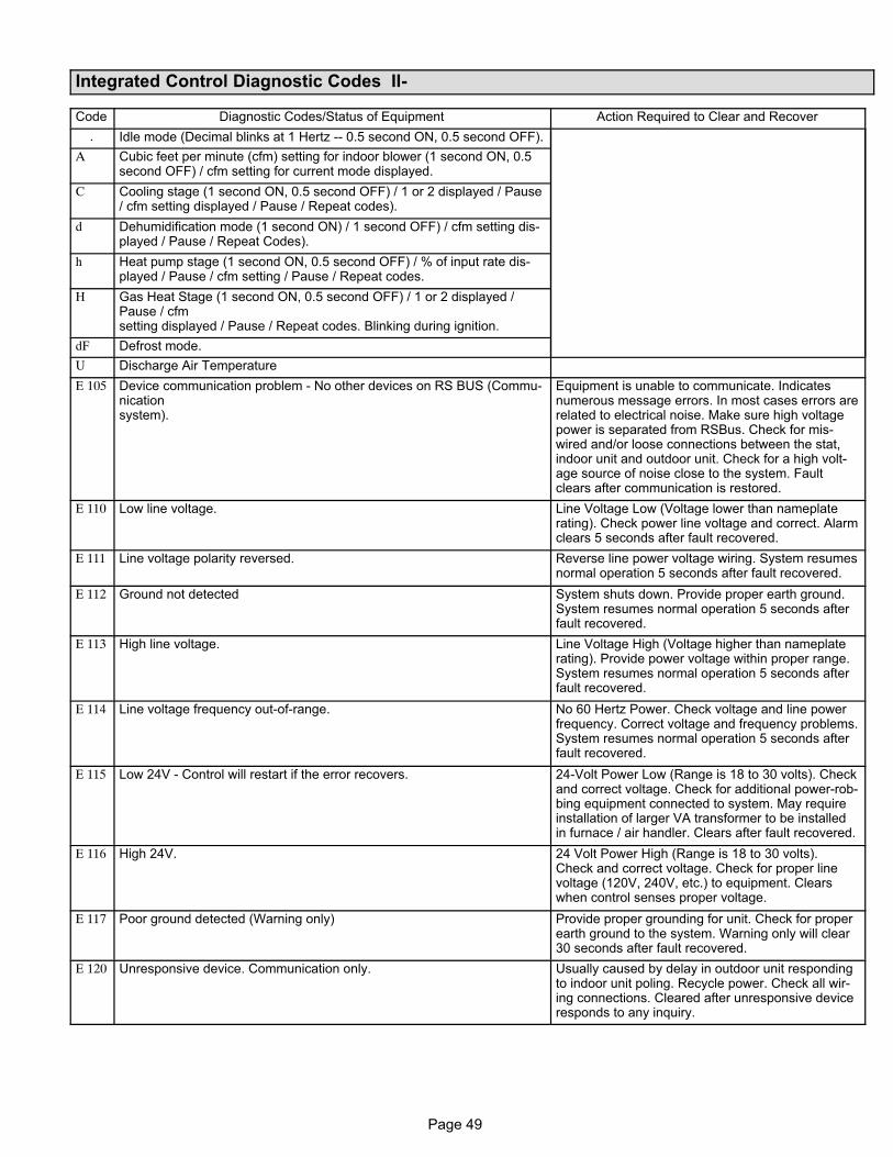
Page 49
Integrated Control Diagnostic Codes II-
Code Diagnostic Codes/Status of Equipment Action Required to Clear and Recover
. Idle mode (Decimal blinks at 1 Hertz -- 0.5 second ON, 0.5 second OFF).
A Cubic feet per minute (cfm) setting for indoor blower (1 second ON, 0.5second OFF) / cfm setting for current mode displayed.
C Cooling stage (1 second ON, 0.5 second OFF) / 1 or 2 displayed / Pause/ cfm setting displayed / Pause / Repeat codes).
d Dehumidification mode (1 second ON) / 1 second OFF) / cfm setting displayed / Pause / Repeat Codes).
h Heat pump stage (1 second ON, 0.5 second OFF) / % of input rate displayed / Pause / cfm setting / Pause / Repeat codes.
H Gas Heat Stage (1 second ON, 0.5 second OFF) / 1 or 2 displayed /Pause / cfmsetting displayed / Pause / Repeat codes. Blinking during ignition.
dF Defrost mode.
U Discharge Air Temperature
E 105 Device communication problem - No other devices on RS BUS (Communicationsystem).
Equipment is unable to communicate. Indicatesnumerous message errors. In most cases errors arerelated to electrical noise. Make sure high voltagepower is separated from RSBus. Check for mis-wired and/or loose connections between the stat,indoor unit and outdoor unit. Check for a high voltage source of noise close to the system. Faultclears after communication is restored.
E 110 Low line voltage. Line Voltage Low (Voltage lower than nameplaterating). Check power line voltage and correct. Alarmclears 5 seconds after fault recovered.
E 111 Line voltage polarity reversed. Reverse line power voltage wiring. System resumesnormal operation 5 seconds after fault recovered.
E 112 Ground not detected System shuts down. Provide proper earth ground.System resumes normal operation 5 seconds afterfault recovered.
E 113 High line voltage. Line Voltage High (Voltage higher than nameplaterating). Provide power voltage within proper range.System resumes normal operation 5 seconds afterfault recovered.
E 114 Line voltage frequency out-of-range. No 60 Hertz Power. Check voltage and line powerfrequency. Correct voltage and frequency problems.System resumes normal operation 5 seconds afterfault recovered.
E 115 Low 24V - Control will restart if the error recovers. 24-Volt Power Low (Range is 18 to 30 volts). Checkand correct voltage. Check for additional power-robbing equipment connected to system. May requireinstallation of larger VA transformer to be installedin furnace / air handler. Clears after fault recovered.
E 116 High 24V. 24 Volt Power High (Range is 18 to 30 volts).Check and correct voltage. Check for proper linevoltage (120V, 240V, etc.) to equipment. Clearswhen control senses proper voltage.
E 117 Poor ground detected (Warning only) Provide proper grounding for unit. Check for properearth ground to the system. Warning only will clear30 seconds after fault recovered.
E 120 Unresponsive device. Communication only. Usually caused by delay in outdoor unit respondingto indoor unit poling. Recycle power. Check all wiring connections. Cleared after unresponsive deviceresponds to any inquiry.
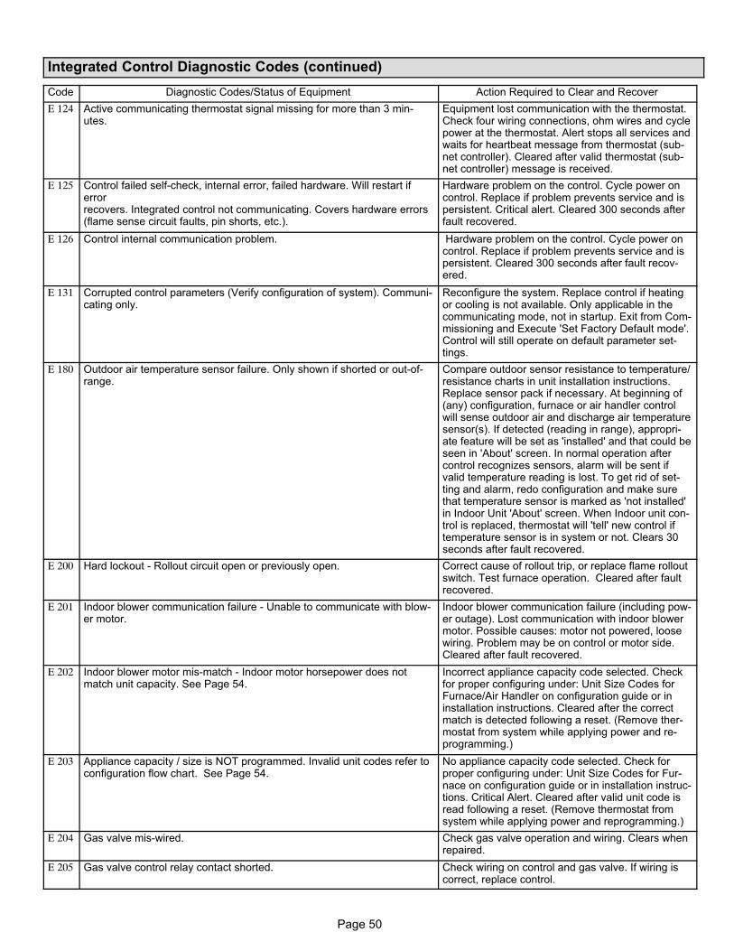
Page 50
Integrated Control Diagnostic Codes (continued)
Code Diagnostic Codes/Status of Equipment Action Required to Clear and Recover
E 124 Active communicating thermostat signal missing for more than 3 minutes.
Equipment lost communication with the thermostat.Check four wiring connections, ohm wires and cyclepower at the thermostat. Alert stops all services andwaits for heartbeat message from thermostat (subnet controller). Cleared after valid thermostat (subnet controller) message is received.
E 125 Control failed self-check, internal error, failed hardware. Will restart iferrorrecovers. Integrated control not communicating. Covers hardware errors(flame sense circuit faults, pin shorts, etc.).
Hardware problem on the control. Cycle power oncontrol. Replace if problem prevents service and ispersistent. Critical alert. Cleared 300 seconds afterfault recovered.
E 126 Control internal communication problem. Hardware problem on the control. Cycle power oncontrol. Replace if problem prevents service and ispersistent. Cleared 300 seconds after fault recovered.
E 131 Corrupted control parameters (Verify configuration of system). Communicating only.
Reconfigure the system. Replace control if heatingor cooling is not available. Only applicable in thecommunicating mode, not in startup. Exit from Commissioning and Execute 'Set Factory Default mode'.Control will still operate on default parameter settings.
E 180 Outdoor air temperature sensor failure. Only shown if shorted or out-of-range.
Compare outdoor sensor resistance to temperature/resistance charts in unit installation instructions.Replace sensor pack if necessary. At beginning of(any) configuration, furnace or air handler controlwill sense outdoor air and discharge air temperaturesensor(s). If detected (reading in range), appropriate feature will be set as 'installed' and that could beseen in 'About' screen. In normal operation aftercontrol recognizes sensors, alarm will be sent ifvalid temperature reading is lost. To get rid of setting and alarm, redo configuration and make surethat temperature sensor is marked as 'not installed'in Indoor Unit 'About' screen. When Indoor unit control is replaced, thermostat will 'tell' new control iftemperature sensor is in system or not. Clears 30seconds after fault recovered.
E 200 Hard lockout - Rollout circuit open or previously open. Correct cause of rollout trip, or replace flame rolloutswitch. Test furnace operation. Cleared after faultrecovered.
E 201 Indoor blower communication failure - Unable to communicate with blower motor.
Indoor blower communication failure (including power outage). Lost communication with indoor blowermotor. Possible causes: motor not powered, loosewiring. Problem may be on control or motor side.Cleared after fault recovered.
E 202 Indoor blower motor mis-match - Indoor motor horsepower does notmatch unit capacity. See Page 54.
Incorrect appliance capacity code selected. Checkfor proper configuring under: Unit Size Codes forFurnace/Air Handler on configuration guide or ininstallation instructions. Cleared after the correctmatch is detected following a reset. (Remove thermostat from system while applying power and reprogramming.)
E 203 Appliance capacity / size is NOT programmed. Invalid unit codes refer toconfiguration flow chart. See Page 54.
No appliance capacity code selected. Check forproper configuring under: Unit Size Codes for Furnace on configuration guide or in installation instructions. Critical Alert. Cleared after valid unit code isread following a reset. (Remove thermostat fromsystem while applying power and reprogramming.)
E 204 Gas valve mis-wired. Check gas valve operation and wiring. Clears whenrepaired.
E 205 Gas valve control relay contact shorted. Check wiring on control and gas valve. If wiring iscorrect, replace control.
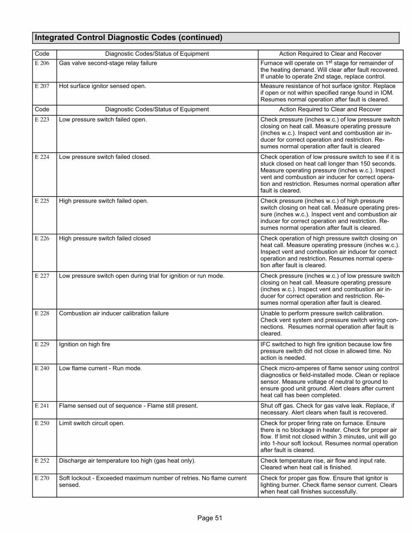
Page 51
Integrated Control Diagnostic Codes (continued)
Code Diagnostic Codes/Status of Equipment Action Required to Clear and Recover
E 206 Gas valve second-stage relay failure Furnace will operate on 1st stage for remainder ofthe heating demand. Will clear after fault recovered.If unable to operate 2nd stage, replace control.
E 207 Hot surface ignitor sensed open. Measure resistance of hot surface ignitor. Replaceif open or not within specified range found in IOM.Resumes normal operation after fault is cleared.
Code Diagnostic Codes/Status of Equipment Action Required to Clear and Recover
E 223 Low pressure switch failed open. Check pressure (inches w.c.) of low pressure switchclosing on heat call. Measure operating pressure(inches w.c.). Inspect vent and combustion air inducer for correct operation and restriction. Resumes normal operation after fault is cleared
E 224 Low pressure switch failed closed. Check operation of low pressure switch to see if it isstuck closed on heat call longer than 150 seconds.Measure operating pressure (inches w.c.). Inspectvent and combustion air inducer for correct operation and restriction. Resumes normal operation afterfault is cleared.
E 225 High pressure switch failed open. Check pressure (inches w.c.) of high pressureswitch closing on heat call. Measure operating pressure (inches w.c.). Inspect vent and combustion airinducer for correct operation and restriction. Resumes normal operation after fault is cleared.
E 226 High pressure switch failed closed Check operation of high pressure switch closing onheat call. Measure operating pressure (inches w.c.).Inspect vent and combustion air inducer for correctoperation and restriction. Resumes normal operation after fault is cleared.
E 227 Low pressure switch open during trial for ignition or run mode. Check pressure (inches w.c.) of low pressure switchclosing on heat call. Measure operating pressure(inches w.c.). Inspect vent and combustion air inducer for correct operation and restriction. Resumes normal operation after fault is cleared.
E 228 Combustion air inducer calibration failure Unable to perform pressure switch calibration.Check vent system and pressure switch wiring connections. Resumes normal operation after fault iscleared.
E 229 Ignition on high fire IFC switched to high fire ignition because low firepressure switch did not close in allowed time. Noaction is needed.
E 240 Low flame current - Run mode. Check micro-amperes of flame sensor using controldiagnostics or field-installed mode. Clean or replacesensor. Measure voltage of neutral to ground toensure good unit ground. Alert clears after currentheat call has been completed.
E 241 Flame sensed out of sequence - Flame still present. Shut off gas. Check for gas valve leak. Replace, ifnecessary. Alert clears when fault is recovered.
E 250 Limit switch circuit open. Check for proper firing rate on furnace. Ensurethere is no blockage in heater. Check for proper airflow. If limit not closed within 3 minutes, unit will gointo 1-hour soft lockout. Resumes normal operationafter fault is cleared.
E 252 Discharge air temperature too high (gas heat only). Check temperature rise, air flow and input rate.Cleared when heat call is finished.
E 270 Soft lockout - Exceeded maximum number of retries. No flame currentsensed.
Check for proper gas flow. Ensure that ignitor islighting burner. Check flame sensor current. Clearswhen heat call finishes successfully.
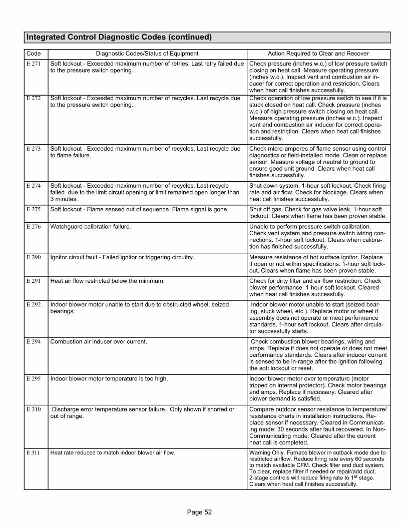
Page 52
Integrated Control Diagnostic Codes (continued)
Code Diagnostic Codes/Status of Equipment Action Required to Clear and Recover
E 271 Soft lockout - Exceeded maximum number of retries. Last retry failed dueto the pressure switch opening.
Check pressure (inches w.c.) of low pressure switchclosing on heat call. Measure operating pressure(inches w.c.). Inspect vent and combustion air inducer for correct operation and restriction. Clearswhen heat call finishes successfully.
E 272 Soft lockout - Exceeded maximum number of recycles. Last recycle dueto the pressure switch opening.
Check operation of low pressure switch to see if it isstuck closed on heat call. Check pressure (inchesw.c.) of high pressure switch closing on heat call.Measure operating pressure (inches w.c.). Inspectvent and combustion air inducer for correct operation and restriction. Clears when heat call finishessuccessfully.
E 273 Soft lockout - Exceeded maximum number of recycles. Last recycle dueto flame failure.
Check micro-amperes of flame sensor using controldiagnostics or field-installed mode. Clean or replacesensor. Measure voltage of neutral to ground toensure good unit ground. Clears when heat callfinishes successfully.
E 274 Soft lockout - Exceeded maximum number of recycles. Last recyclefailed due to the limit circuit opening or limit remained open longer than3 minutes.
Shut down system. 1-hour soft lockout. Check firingrate and air flow. Check for blockage. Clears whenheat call finishes successfully.
E 275 Soft lockout - Flame sensed out of sequence. Flame signal is gone. Shut off gas. Check for gas valve leak. 1-hour softlockout. Clears when flame has been proven stable.
E 276 Watchguard calibration failure. Unable to perform pressure switch calibration.Check vent system and pressure switch wiring connections. 1-hour soft lockout. Clears when calibration has finished successfully.
E 290 Ignitor circuit fault - Failed ignitor or triggering circuitry. Measure resistance of hot surface ignitor. Replaceif open or not within specifications. 1-hour soft lockout. Clears when flame has been proven stable.
E 291 Heat air flow restricted below the minimum. Check for dirty filter and air flow restriction. Checkblower performance. 1-hour soft lockout. Clearedwhen heat call finishes successfully.
E 292 Indoor blower motor unable to start due to obstructed wheel, seizedbearings.
Indoor blower motor unable to start (seized bearing, stuck wheel, etc.). Replace motor or wheel ifassembly does not operate or meet performancestandards. 1-hour soft lockout. Clears after circulator successfully starts.
E 294 Combustion air inducer over current. Check combustion blower bearings, wiring andamps. Replace if does not operate or does not meetperformance standards. Clears after inducer currentis sensed to be in-range after the ignition followingthe soft lockout or reset.
E 295 Indoor blower motor temperature is too high. Indoor blower motor over temperature (motortripped on internal protector). Check motor bearingsand amps. Replace if necessary. Cleared afterblower demand is satisfied.
E 310 Discharge error temperature sensor failure. Only shown if shorted orout of range.
Compare outdoor sensor resistance to temperature/resistance charts in installation instructions. Replace sensor if necessary. Cleared in Communicating mode: 30 seconds after fault recovered. In Non-Communicating mode: Cleared after the currentheat call is completed.
E 311 Heat rate reduced to match indoor blower air flow. Warning Only. Furnace blower in cutback mode due torestricted airflow. Reduce firing rate every 60 secondsto match available CFM. Check filter and duct system.To clear, replace filter if needed or repair/add duct.2-stage controls will reduce firing rate to 1st stage.Clears when heat call finishes successfully.
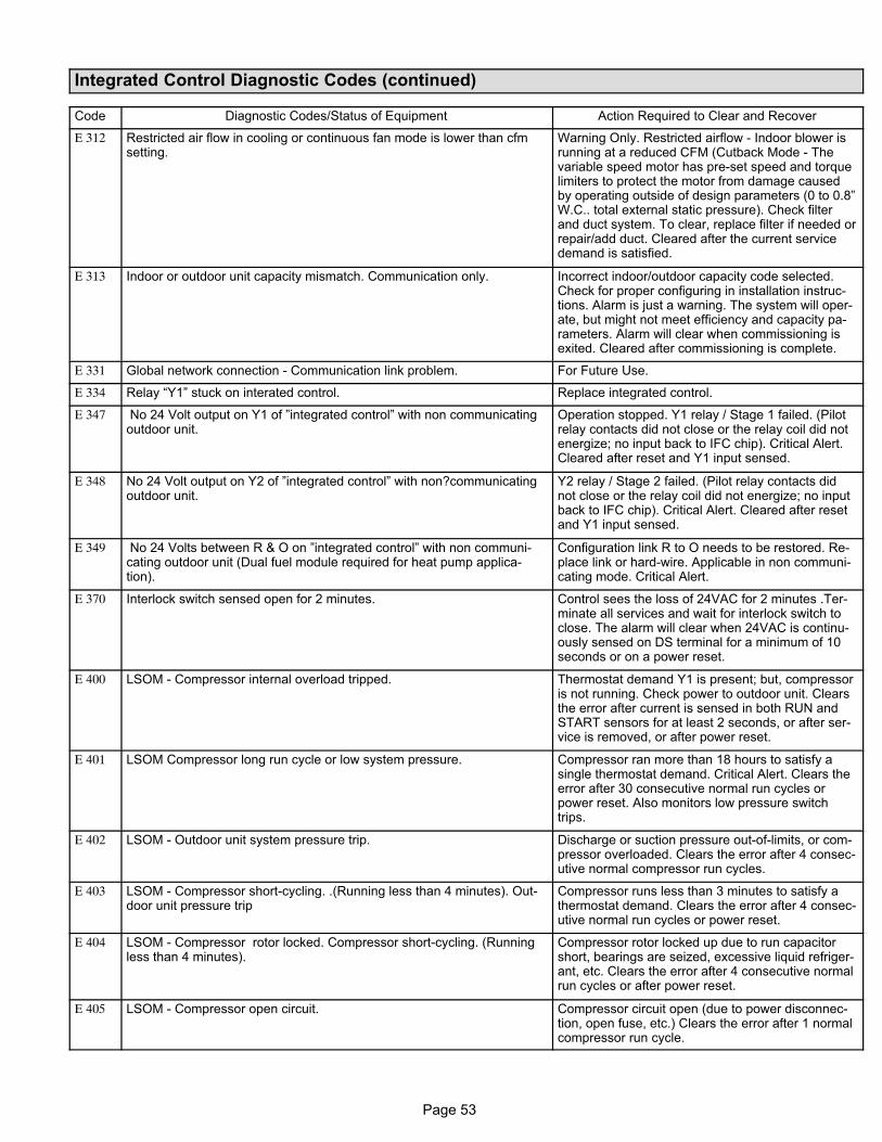
Page 53
Integrated Control Diagnostic Codes (continued)
Code Diagnostic Codes/Status of Equipment Action Required to Clear and Recover
E 312 Restricted air flow in cooling or continuous fan mode is lower than cfmsetting.
Warning Only. Restricted airflow - Indoor blower isrunning at a reduced CFM (Cutback Mode - Thevariable speed motor has pre-set speed and torquelimiters to protect the motor from damage causedby operating outside of design parameters (0 to 0.8”W.C.. total external static pressure). Check filterand duct system. To clear, replace filter if needed orrepair/add duct. Cleared after the current servicedemand is satisfied.
E 313 Indoor or outdoor unit capacity mismatch. Communication only. Incorrect indoor/outdoor capacity code selected.Check for proper configuring in installation instructions. Alarm is just a warning. The system will operate, but might not meet efficiency and capacity parameters. Alarm will clear when commissioning isexited. Cleared after commissioning is complete.
E 331 Global network connection - Communication link problem. For Future Use.
E 334 Relay “Y1” stuck on interated control. Replace integrated control.
E 347 No 24 Volt output on Y1 of ”integrated control” with non communicatingoutdoor unit.
Operation stopped. Y1 relay / Stage 1 failed. (Pilotrelay contacts did not close or the relay coil did notenergize; no input back to IFC chip). Critical Alert.Cleared after reset and Y1 input sensed.
E 348 No 24 Volt output on Y2 of ”integrated control” with non?communicatingoutdoor unit.
Y2 relay / Stage 2 failed. (Pilot relay contacts didnot close or the relay coil did not energize; no inputback to IFC chip). Critical Alert. Cleared after resetand Y1 input sensed.
E 349 No 24 Volts between R & O on ”integrated control” with non communicating outdoor unit (Dual fuel module required for heat pump application).
Configuration link R to O needs to be restored. Replace link or hard-wire. Applicable in non communicating mode. Critical Alert.
E 370 Interlock switch sensed open for 2 minutes. Control sees the loss of 24VAC for 2 minutes .Terminate all services and wait for interlock switch toclose. The alarm will clear when 24VAC is continuously sensed on DS terminal for a minimum of 10seconds or on a power reset.
E 400 LSOM - Compressor internal overload tripped. Thermostat demand Y1 is present; but, compressoris not running. Check power to outdoor unit. Clearsthe error after current is sensed in both RUN andSTART sensors for at least 2 seconds, or after service is removed, or after power reset.
E 401 LSOM Compressor long run cycle or low system pressure. Compressor ran more than 18 hours to satisfy asingle thermostat demand. Critical Alert. Clears theerror after 30 consecutive normal run cycles orpower reset. Also monitors low pressure switchtrips.
E 402 LSOM - Outdoor unit system pressure trip. Discharge or suction pressure out-of-limits, or compressor overloaded. Clears the error after 4 consecutive normal compressor run cycles.
E 403 LSOM - Compressor short-cycling. .(Running less than 4 minutes). Outdoor unit pressure trip
Compressor runs less than 3 minutes to satisfy athermostat demand. Clears the error after 4 consecutive normal run cycles or power reset.
E 404 LSOM - Compressor rotor locked. Compressor short-cycling. (Runningless than 4 minutes).
Compressor rotor locked up due to run capacitorshort, bearings are seized, excessive liquid refrigerant, etc. Clears the error after 4 consecutive normalrun cycles or after power reset.
E 405 LSOM - Compressor open circuit. Compressor circuit open (due to power disconnection, open fuse, etc.) Clears the error after 1 normalcompressor run cycle.
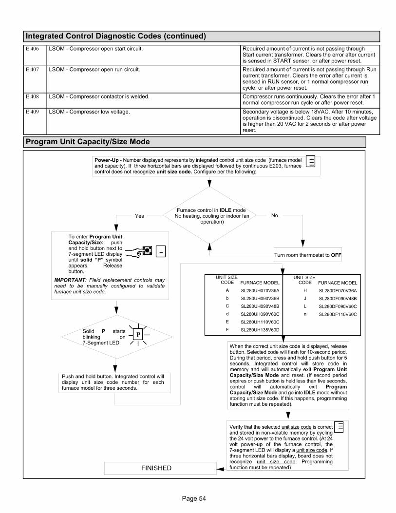
Page 54
Integrated Control Diagnostic Codes (continued)
E 406 LSOM - Compressor open start circuit. Required amount of current is not passing throughStart current transformer. Clears the error after currentis sensed in START sensor, or after power reset.
E 407 LSOM - Compressor open run circuit. Required amount of current is not passing through Runcurrent transformer. Clears the error after current issensed in RUN sensor, or 1 normal compressor runcycle, or after power reset.
E 408 LSOM - Compressor contactor is welded. Compressor runs continuously. Clears the error after 1normal compressor run cycle or after power reset.
E 409 LSOM - Compressor low voltage. Secondary voltage is below 18VAC. After 10 minutes,operation is discontinued. Clears the code after voltageis higher than 20 VAC for 2 seconds or after powerreset.
Program Unit Capacity/Size Mode
Power-Up - Number displayed represents by integrated control unit size code (furnace modeland capacity). If three horizontal bars are displayed followed by continuous E203, furnacecontrol does not recognize unit size code. Configure per the following:
Furnace control in IDLE mode No heating, cooling or indoor fan
operation)
To enter Program UnitCapacity/Size: pushand hold button next to7-segment LED displayuntil solid “P” symbolappears. Releasebutton.
Turn room thermostat to OFF
Solid P startsblinking on7-Segment LED
Push and hold button. Integrated control willdisplay unit size code number for eachfurnace model for three seconds.
When the correct unit size code is displayed, releasebutton. Selected code will flash for 10-second period.During that period, press and hold push button for 5seconds. Integrated control will store code inmemory and will automatically exit Program UnitCapacity/Size Mode and reset. (If second periodexpires or push button is held less than five seconds,control will automatically exit ProgramCapacity/Size Mode and go into IDLE mode withoutstoring unit size code. If this happens, programmingfunction must be repeated).
Verify that the selected unit size code is correctand stored in non-volatile memory by cyclingthe 24 volt power to the furnace control. (At 24volt power-up of the furnace control, the7-segment LED will display a unit size code. Ifthree horizontal bars display, board does notrecognize unit size code. Programmingfunction must be repeated)
Yes No
IMPORTANT: Field replacement controls mayneed to be manually configured to validatefurnace unit size code.
FURNACE MODEL
SL280UH070V36A
SL280UH090V36B
SL280UH090V48B
SL280UH090V60C
SL280UH110V60C
SL280UH135V60D
UNIT SIZE CODE
A
b
C
d
E
F
−−−
_
P
−−−
FINISHED
FURNACE MODEL
SL280DF070V36A
SL280DF090V48B
SL280DF090V60C
SL280DF110V60C
UNIT SIZE CODE
H
J
L
n
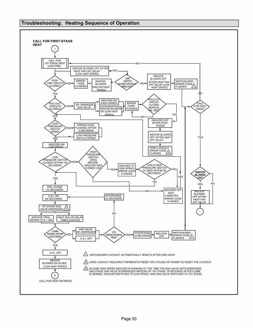
Page 55
Troubleshooting: Heating Sequence of Operation
HIGHLIMIT SWITCH
CLOSED?
LOWPRESSURE
SWITCHOPEN?
INDUCER ON
PRE−PURGE(15 SECONDS)
1ST STAGE GASVALVE ENERGIZED
FLAMESENSED WITHIN
4 SECONDS?
(LOW HEAT SPEED)
HEAT FAN OFF DELAY(LOW HEAT SPEED)
AFTER HEAT FANOFF DELAY (LOW
HEAT SPEED)
YES
YES
YES
YES
ERRORCODE
FLASHES ON(LOW HEATSPEED)
NO
NO
NO
NO
CALLFOR HEAT
ENDS?
ERROR CODEFLASHES (AFTER
5 SECONDS)
5THUNSUCCESSFUL
TRIAL?
POSTPURGE(5 SECONDS)
INDUCEROFF
NO
YES
NO
NO
ROLLOUTCIRCUITSCLOSED?
DE−ENERGIZEGAS VALVE
ERRORCODE
FLASHESINDOOR BLOWER ON (LOW HEAT
SPEED)
INDUCER ON (HIGH SPEED)
LIMITSWITCH
CLOSED WITHIN 3MINUTES?
CALL FOR 1ST STAGE HEAT
(LOW FIRE)
NO
GAS VALVEDE−ENERGIZED
H.S.I. OFF
H.S.I. ON(20 SECONDS)
WATCHGUARD −ERROR CODE FLASHES
CALL FOR HEAT SATISFIED
IGNITION TRIAL BEGINS (H.S.I. ON)
HEAT FAN ON DELAYTIMER STARTED
INTERPURGE(15 SECONDS)
H.S.I. OFF
NOINDUCER OFFAFTER POST
PURGE
HARD LOCKOUT − ERROR CODE FLASHES
YES
YES
YES
1
2
1
LOW PRESSURE SWITCH OPENS
1
2 HARD LOCKOUT REQUIRES THERMOSTAT RESET OR CYCLING OF POWER TO RESET THE LOCKOUT.
3 IN CASE HIGH SPEED INDUCER IS RUNNING AT THE TIME THE GAS VALVE GETS ENERGIZED,2ND STAGE GAS VALVE IS ENERGIZED INSTEAD OF 1ST STAGE. 20 SECONDS AFTER FLAMEIS SENSED, INDUCER SWITCHES TO LOW SPEED, AND GAS VALVE SWITCHES TO 1ST STAGE.
1
2
1
NO
LOWPRESSURE SWITCHCLOSED WITHIN 120
SECONDS? LOW & HIGHPRESSURE SWITCHCLOSED WITHIN 30
SECONDS?
HIGHPRESSURE
SWITCHOPEN
BEFOREINDUCER WASTURNED ON?
INDUCER TOHIGH SPEED−ERROR CODE
FLASHES
NO
INDUCER OFF−WAIT
5 MINUTESERROR CODE
FLASHES
YES
YES
YES
YES
NO
3
INDOOR BLOWER OFF AFTER
INDOORBLOWER OFF
INDOORBLOWER
ROLLOUTCIRCUITCLOSES(MANUALRE−SET)
NO
LOW SPEED
INDOOR BLOWEROFF AFTER HEATOFF DELAY
YES
INDOORBLOWER
ON?
WATCHGUARD −ERROR CODE FLASHES
INDOORBLOWER
ON?
INDOORBLOWER ON 30 SEC.
WATCHGUARD LOCKOUT AUTOMATICALLY RESETS AFTER ONE HOUR
CALL FOR FIRST-STAGEHEAT
INDOORBLOWER
OFF AFTERHEAT FAN
OFF DELAY
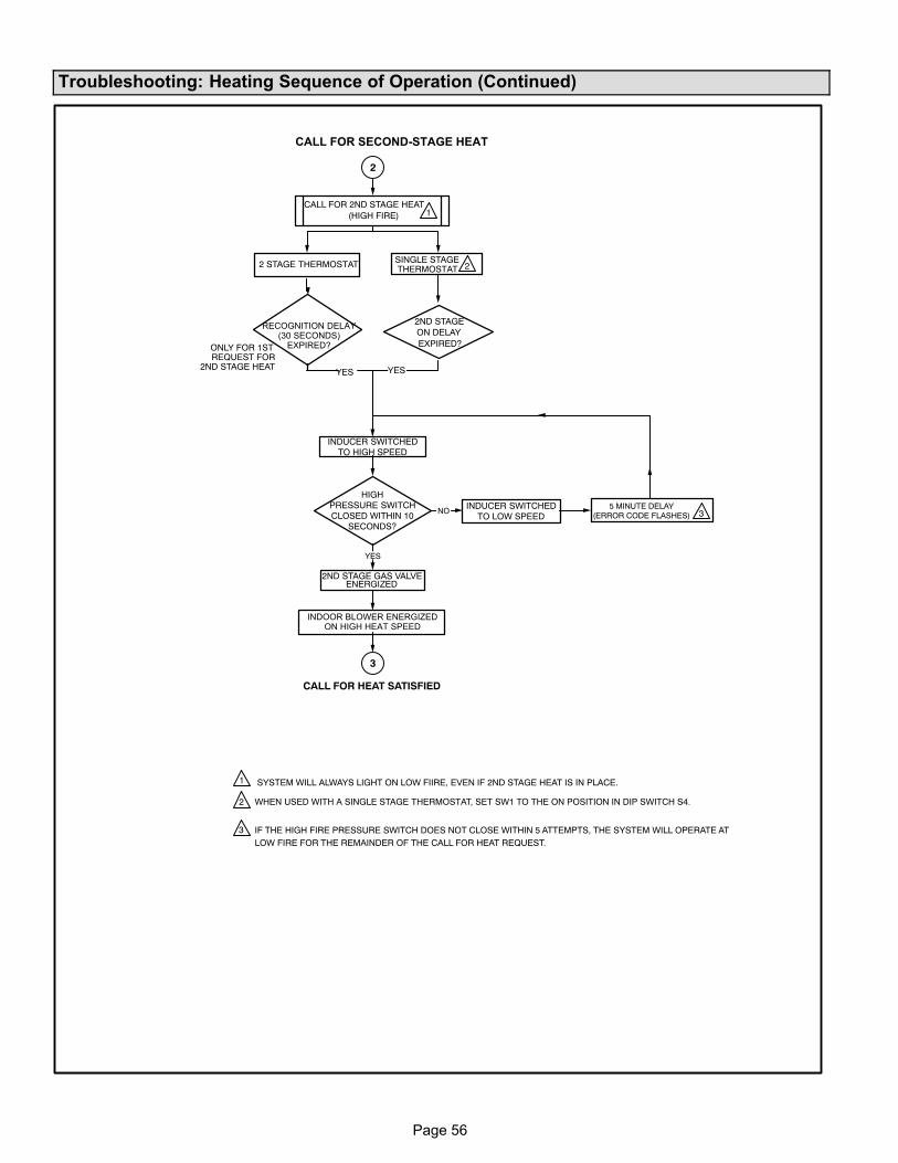
Page 56
Troubleshooting: Heating Sequence of Operation (Continued)
WHEN USED WITH A SINGLE STAGE THERMOSTAT, SET SW1 TO THE ON POSITION IN DIP SWITCH S4.
IF THE HIGH FIRE PRESSURE SWITCH DOES NOT CLOSE WITHIN 5 ATTEMPTS, THE SYSTEM WILL OPERATE ATLOW FIRE FOR THE REMAINDER OF THE CALL FOR HEAT REQUEST.
2ND STAGE GAS VALVEENERGIZED
ONLY FOR 1STREQUEST FOR
2ND STAGE HEAT
YES
CALL FOR HEAT SATISFIED
INDUCER SWITCHEDTO HIGH SPEED
SINGLE STAGETHERMOSTAT2 STAGE THERMOSTAT
NOINDUCER SWITCHED
TO LOW SPEED5 MINUTE DELAY
(ERROR CODE FLASHES)
HIGHPRESSURE SWITCHCLOSED WITHIN 10
SECONDS?
2ND STAGEON DELAYEXPIRED?
CALL FOR 2ND STAGE HEAT(HIGH FIRE)
2
3
1
2
3
1
2
3
YESYES
CALL FOR SECOND-STAGE HEAT
RECOGNITION DELAY(30 SECONDS)
EXPIRED?
INDOOR BLOWER ENERGIZEDON HIGH HEAT SPEED
SYSTEM WILL ALWAYS LIGHT ON LOW FIIRE, EVEN IF 2ND STAGE HEAT IS IN PLACE.
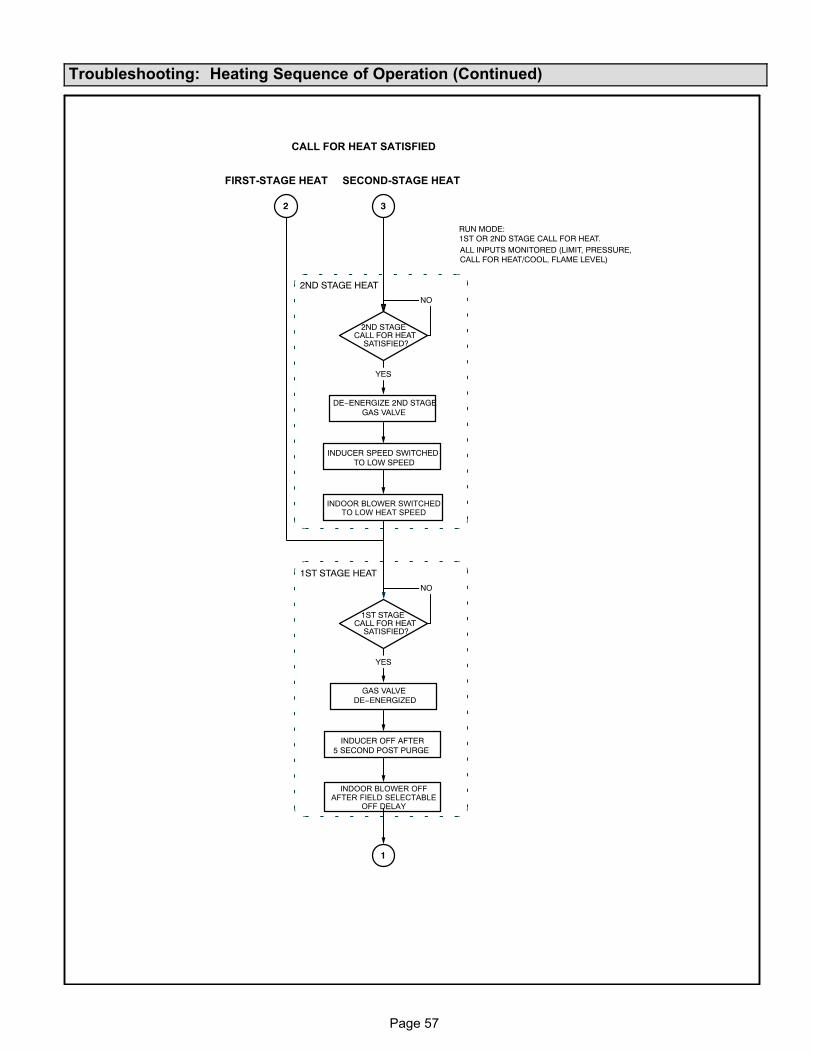
Page 57
Troubleshooting: Heating Sequence of Operation (Continued)
2ND STAGE HEAT
RUN MODE:1ST OR 2ND STAGE CALL FOR HEAT.ALL INPUTS MONITORED (LIMIT, PRESSURE,CALL FOR HEAT/COOL, FLAME LEVEL)
2ND STAGECALL FOR HEAT
SATISFIED?
NO
YES
DE−ENERGIZE 2ND STAGEGAS VALVE
INDUCER SPEED SWITCHEDTO LOW SPEED
1
2 3
1ST STAGE HEAT
1ST STAGECALL FOR HEAT
SATISFIED?
NO
YES
GAS VALVEDE−ENERGIZED
INDUCER OFF AFTER5 SECOND POST PURGE
CALL FOR HEAT SATISFIED
FIRST-STAGE HEAT SECOND-STAGE HEAT
INDOOR BLOWER SWITCHEDTO LOW HEAT SPEED
INDOOR BLOWER OFFAFTER FIELD SELECTABLE
OFF DELAY
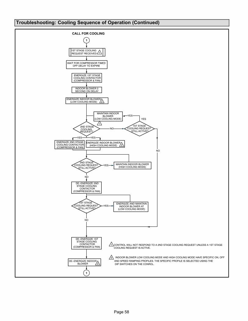
Page 58
Troubleshooting: Cooling Sequence of Operation (Continued)
1ST STAGE COOLINGREQUEST RECEIVED
ENERGIZE 1ST STAGECOOLING CONTACTOR(COMPRESSOR & FAN)
2ND STAGECOOLINGREQUEST?
NO
YES
YES
YES
NO
1ST STAGECOOLING REQUEST
STILL ACTIVE?
NO
YES
YES
ENERGIZE 2ND STAGECOOLING CONTACTOR(COMPRESSOR & FAN)
DE−ENERGIZE 2NDSTAGE COOLING
CONTACTOR(COMPRESSOR & FAN)
NO
CONTROL WILL NOT RESPOND TO A 2ND STAGE COOLING REQUEST UNLESS A 1ST STAGECOOLING REQUEST IS ACTIVE.
AND SPEED RAMPING PROFILES. THE SPECIFIC PROFILE IS SELECTED USING THE
1
1
2
2
1
1
1
2
2
DE−ENERGIZE 1STSTAGE COOLING
CONTACTOR(COMPRESSOR & FAN)
2ND STAGECOOLING REQUEST
STILL ACTIVE?
COOLING REQUESTSTILL ACTIVE?
CALL FOR COOLING
WAIT FOR COMPRESSOR TIMEDOFF DELAY TO EXPIRE
INDOOR BLOWER 2SECOND ON DELAY
YES
1ST STAGE
DE−ENERGIZE INDOORBLOWER
INDOOR BLOWER LOW COOLING MODE AND HIGH COOLING MODE HAVE SPECIFIC ON, OFF
ENERGIZE INDOOR BLOWER(LOW COOLING MODE)
ENERGIZE INDOOR BLOWER(HIGH COOLING MODE)
MAINTAIN INDOOR BLOWER(HIGH COOLING MODE)
ENERGIZE AND MAINTAININDOOR BLOWER AT
(LOW COOLING MODE)
DIP SWITCHES ON THE CONROL.
MAINTAIN INDOORBLOWER
(LOW COOLING MODE)
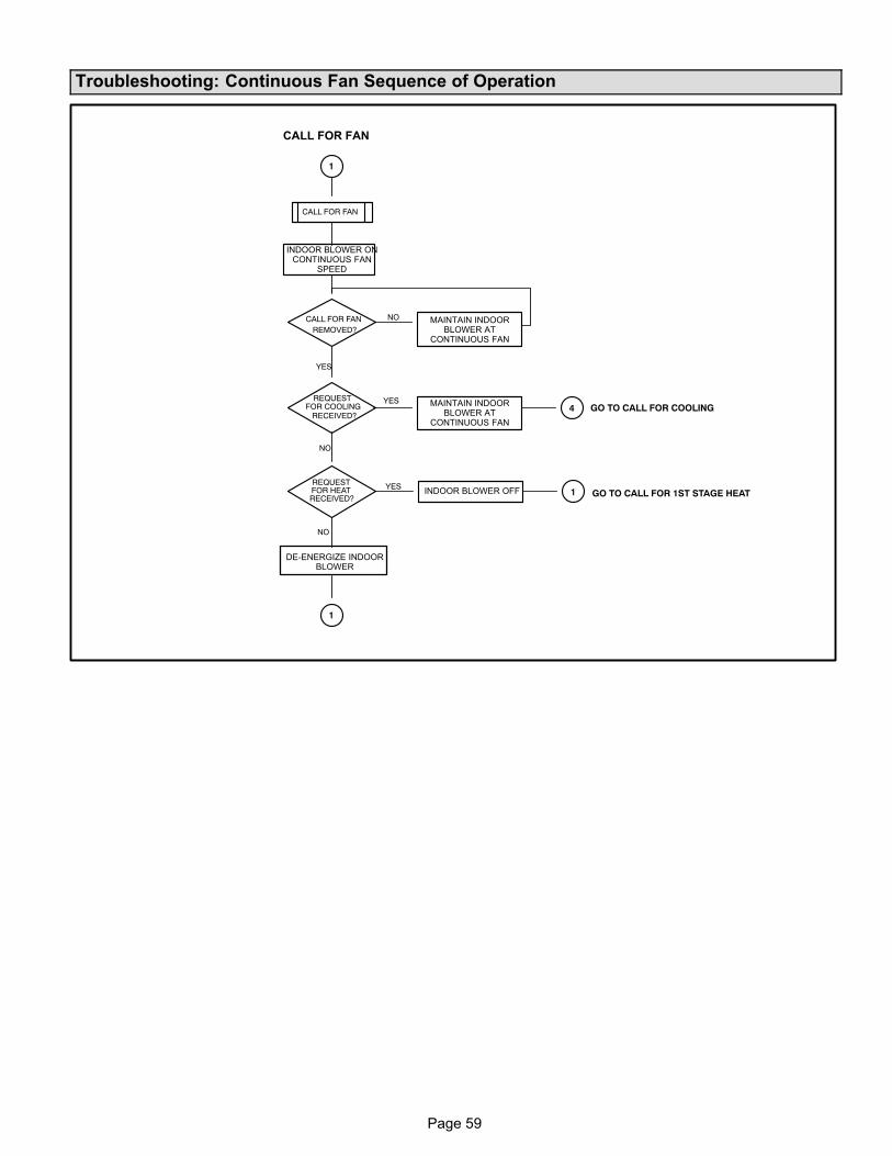
Page 59
Troubleshooting: Continuous Fan Sequence of Operation
CALL FOR FAN
CALL FOR FANREMOVED?
YES
NO
NO
REQUESTFOR HEATRECEIVED?
REQUESTFOR COOLING
RECEIVED?
GO TO CALL FOR 1ST STAGE HEAT
YESGO TO CALL FOR COOLING
1
1
1
4
YES
NO
CALL FOR FAN
INDOOR BLOWER ONCONTINUOUS FAN
SPEED
MAINTAIN INDOORBLOWER AT
CONTINUOUS FAN
MAINTAIN INDOORBLOWER AT
CONTINUOUS FAN
INDOOR BLOWER OFF
DE-ENERGIZE INDOORBLOWER