Embed Size (px)
Citation preview

Manufacturer reserves the right to discontinue, or change at any time, specifications or designs without notice and without incurring obligations.Catalog No. 04-53300104-01 Printed in U.S.A. Form 30/38-11SI Pg 1 11-12 Replaces: 30/38-7SI
Installation InstructionsPart Number 38AP-900---022
CONTENTS
SAFETY CONSIDERATIONS . . . . . . . . . . . . . . . . . . . . . . 1GENERAL . . . . . . . . . . . . . . . . . . . . . . . . . . . . . . . . . . . . . . . . 1INSTALLATION . . . . . . . . . . . . . . . . . . . . . . . . . . . . . . . . 1-10Install Harness and Make Wire
Connections . . . . . . . . . . . . . . . . . . . . . . . . . . . . . . . . . . . 5Controls Configuration for EMM Options . . . . . . . . . 6
SAFETY CONSIDERATIONS
Installation of this accessory can be hazardous due to sys-tem pressures, electrical components, and equipment loca-tion (such as a roof or elevated structure).Only trained, qualified installers and service techniciansshould install, start up, and service this equipment.When installing this accessory, observe precautions in theliterature, labels attached to the equipment, and any othersafety precautions that apply.• Follow all safety codes.• Wear safety glasses and work gloves.• Use care in handling and installing this accessory.
GENERALThe energy management module (EMM) accessory (Fig. 1)package is required for additional temperature reset, de-mand limit, and remote set point features of the Com-fortLink controls for 30MP, 30RAP and 38AP units.Chilled water temperature reset by return water, outside airor space temperature do NOT require the addition of this ac-cessory. The following additional features are supported bythis accessory:• temperature reset by 4 to 20 mA field-supplied signal.• demand limit control via field-supplied two-step switch
input.• demand limit control by 4 to 20 mA field-supplied
signal.• support of unoccupied operation for ice making through
field-supplied contacts (30MP, 30RAP only).• cooling set point control by 4 to 20 mA field-supplied
signal.
ACCESSORY PACKAGE CONTENTS
LEGEND
INSTALLATION
NOTE: Component arrangement drawings and wiring dia-grams show available options that may not be applicable toyour unit.
1. Inspect the package contents for missing or damagedparts. File a claim with shipping agency if parts are dam-aged. Notify your Carrier representative if any items aremissing.
2. Open and tag all electrical disconnects.3. Access control box:
a. Model 30RAP010-030, 30MP015-045 and38AP025-030 units: Open control box door andremove inner cover.
b. Model 30RAP035-150 and 38AP040-130 units:Open center control box door.
4. For 30RAP and 38AP units, loosen the four screws secur-ing the scrolling marquee display bracket. Lift the bracketup and slide it in the holding slots at the top of its mount-ing bracket. For 30MP units, carefully suspend the display bracketfrom the wiring harness.
WARNING
Electrical shock can cause personal injury and death. Shutoff all power to this equipment during installation. Theremay be more than one disconnect switch. Tag all discon-nect locations to alert others not to restore power until workis completed.
ITEM PART NO. QUANTITYEnergy Management Module 30GT515218 1Harness (38APD,S025-060) 38APHLSBCE-A00 1Harness (38APD,S065-130) 38APHLSLCE-A00 1Harness, EMM to LVT(30RAP, 30MP) 38APHSCALE-A00 1
Harness, EMM to MBB/EXV(Power - 30RAP, 30MP) 38APHSCALECA10 1
Harness, EMM to MBB/EXV(Comm. - 30RAP, 30MP) 38APHSCALECA00 1
Harness, EMM to AUX(Comm. - 30RAP, 30MP) 38APHSCALXCA00 1
Screw, no. 6, 1-in. long AL56AU130 1Wire Tie — 4
EXV — Electronic Expansion ValveLVT — Low Voltage TerminalMBB — Main Base Board
WARNING
Before beginning installation of this equipment, be sure allpower to the unit is disconnected, and that tags are properlyplaced to alert others. Electrical shock can cause personalinjury and death.
30MP015-045, 30RAP010-15038APD025-130, 38APS025-065
Energy Management Module (EMM) Accessory50/60 Hz
2
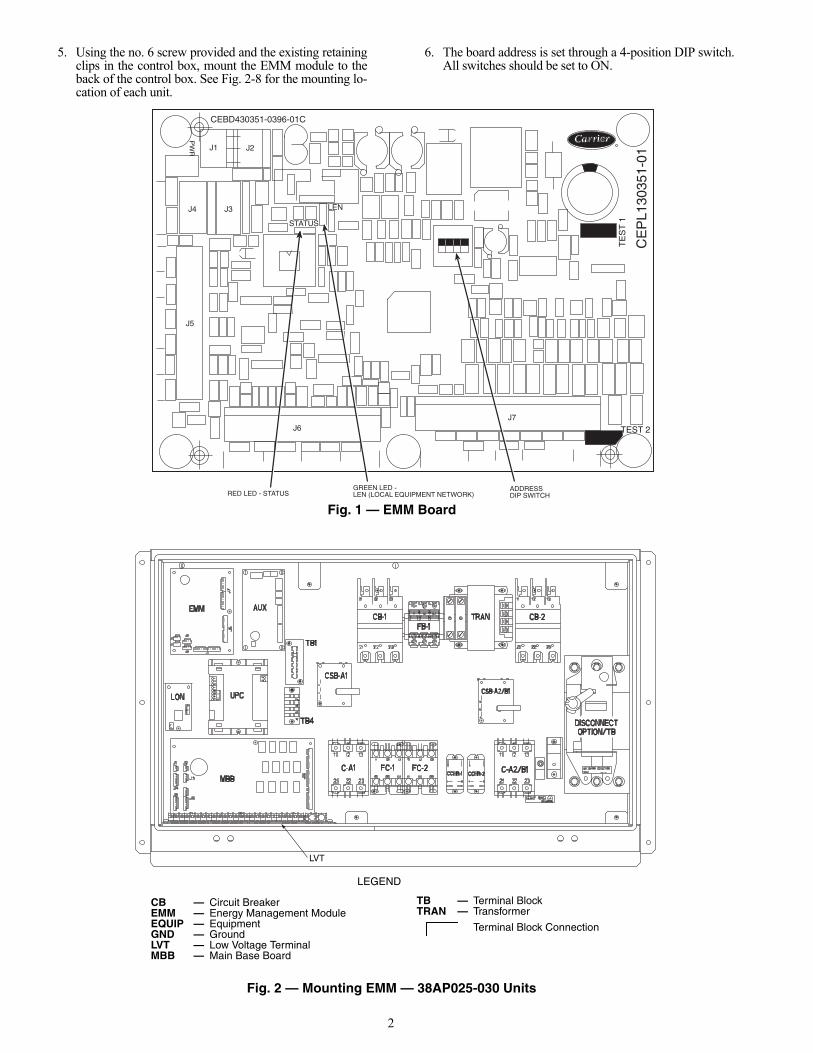
5. Using the no. 6 screw provided and the existing retainingclips in the control box, mount the EMM module to theback of the control box. See Fig. 2-8 for the mounting lo-cation of each unit.
6. The board address is set through a 4-position DIP switch.All switches should be set to ON.
CEBD430351-0396-01C
TE
ST
1
CE
PL1
3035
1-01
PW
R
TEST 2
J1 J2
J4 J3
J5
J6J7
LEN
STATUS
RED LED - STATUSGREEN LED -LEN (LOCAL EQUIPMENT NETWORK)
ADDRESSDIP SWITCH
Fig. 1 — EMM Board
LVT
Fig. 2 — Mounting EMM — 38AP025-030 Units
LEGEND
CB — Circuit BreakerEMM — Energy Management ModuleEQUIP — EquipmentGND — GroundLVT — Low Voltage TerminalMBB — Main Base Board
TB — Terminal BlockTRAN — Transformer
Terminal Block Connection a30-4937
3
LVT
LVT
EMM EXV
LON
AUX
UPC
TB1 TB4
CSB-A1
MBB
CHCCCB
FB-1TRAN
DISCONNECTOPTION/TB
C-A1MM
MS-CWP1
CWP1
MS-CWP2
CWP2
LVT
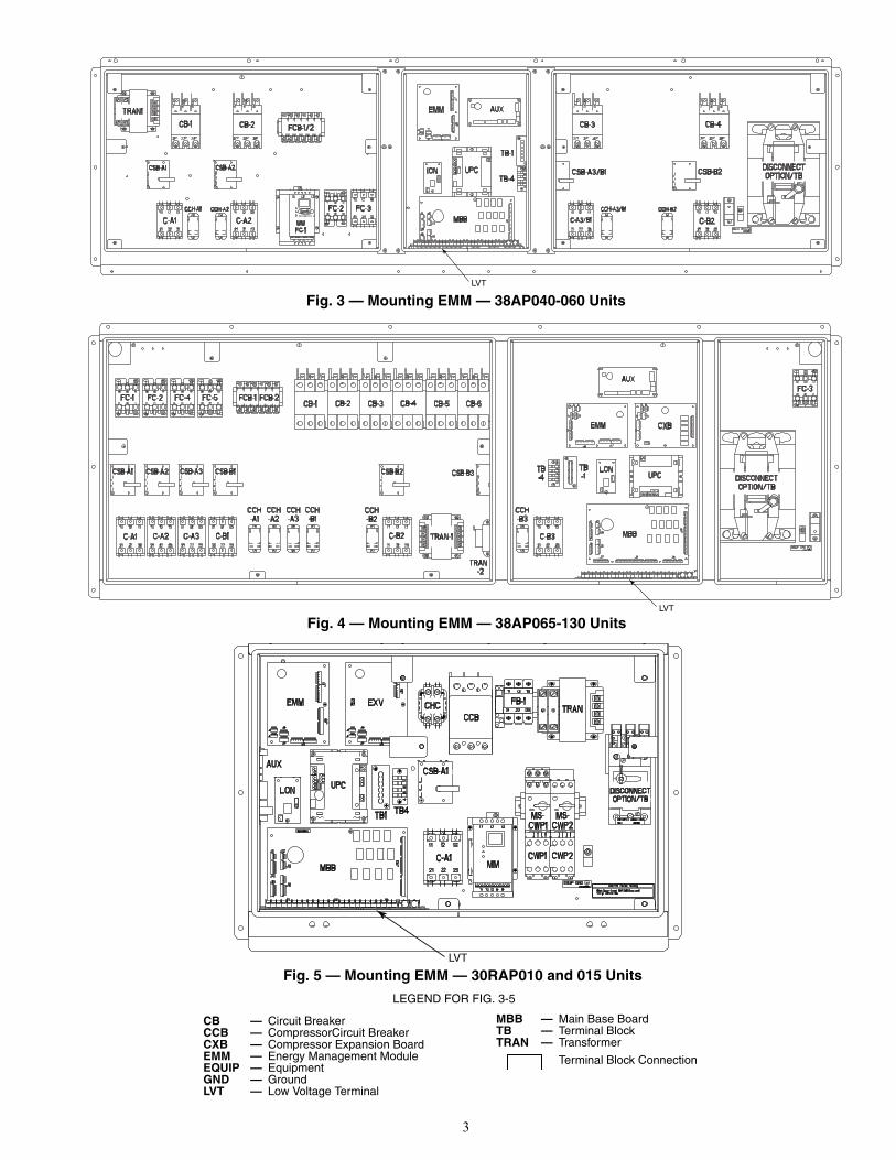
Fig. 4 — Mounting EMM — 38AP065-130 Units
Fig. 5 — Mounting EMM — 30RAP010 and 015 Units
LEGEND FOR FIG. 3-5
CB — Circuit BreakerCCB — CompressorCircuit BreakerCXB — Compressor Expansion BoardEMM — Energy Management ModuleEQUIP — EquipmentGND — GroundLVT — Low Voltage Terminal
MBB — Main Base BoardTB — Terminal BlockTRAN — Transformer
Terminal Block Connection
Fig. 3 — Mounting EMM — 38AP040-060 Units a30-4938
a30-4939
a30-4940
4
a30-4941
a30-4942
EMM EXV
CCB-1
TB1
TB4
CHC
AUX
LON UPC
FC1/MM
CSB-A1
MBBC-A1
FB-3TRAN
CCB-2
CSB-A2
DISCONNECTOPTION/TB
FC2 C-A2
FB-1
CWP1 CWP2
MS-CWP1
MS-CWP2
LVT
TRAN-1
CB-1 CB-2 FCB-1/2/3
TRAN-2CSB-A1 CSB-A2
C-A1
FR-1 FR-2
C-A2
FC-1MM
FC-2 FC-3
AUX LON
EMM EXV
UPC
TB1
TB4
MBB
MS-CWP1
MS-CWP2
FR-3
C-B1
CSB-B1
CB-3CHC
CWP1 CWP2FR-4
CSB-B2
C-B2
CB-4
DISCONNECTOPTION/TB
LVT
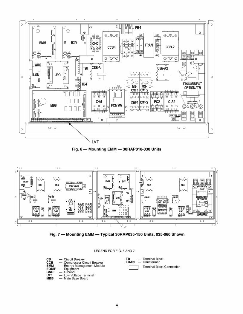
Fig. 6 — Mounting EMM — 30RAP018-030 Units
Fig. 7 — Mounting EMM — Typical 30RAP035-150 Units, 035-060 Shown
LEGEND FOR FIG. 6 AND 7
CB — Circuit BreakerCCB — Compressor Circuit BreakerEMM — Energy Management ModuleEQUIP — EquipmentGND — GroundLVT — Low Voltage TerminalMBB — Main Base Board
TB — Terminal BlockTRAN — Transformer
Terminal Block Connection
5
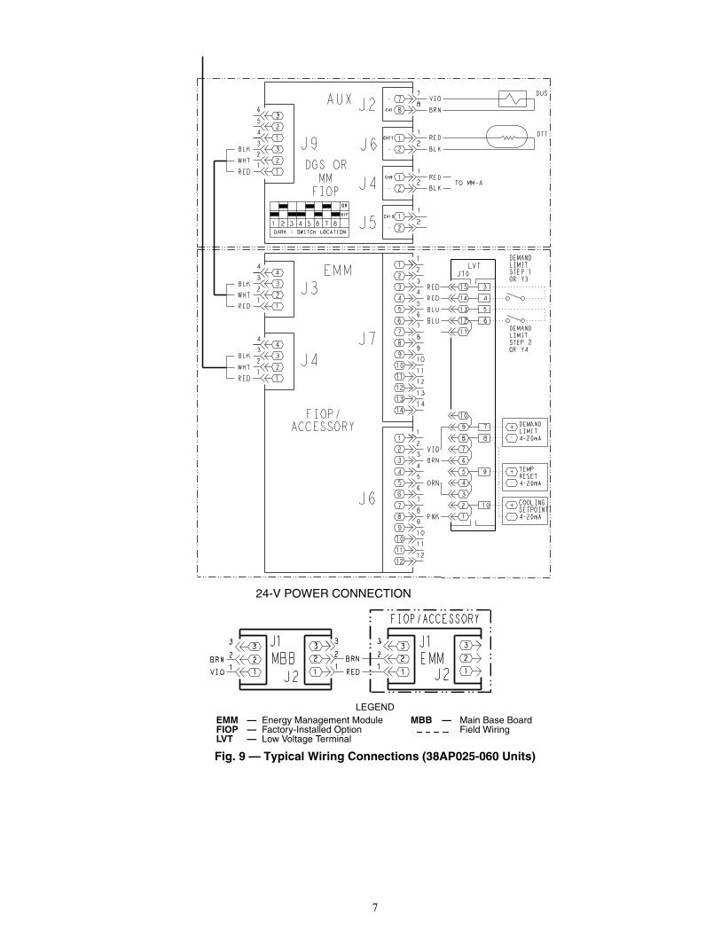
Install Harness and Make Wire Connections38AP025-060 UNITS WITH AUX BOARD — Perform thefollowing procedure to install the harness and make the wiringconnections. See Fig. 9 for wiring.
1. Disconnect the MBB-J3 connector and plug it into theEMM-J3 connector.
2. Install the new harness 38APHLSBCE-A00 provided.a. Install plug labeled MBB-J3 to MBB-J3 and other
end labeled EMM-J4 to EMM-J4.b. Install plug labeled MBB-J2 connector to MBB-J2
and other end labeled EMM-J1 to EMM-J1.c. Install plugs labeled EMM-J6 and J7 to EMM-J6
and J7 and other end labeled LVT-J10 to LVT ter-minal strip.
38AP025-060 UNITS WITHOUT AUX BOARD — Per-form the following procedure to install the harness andmake the wiring connections. See Fig. 9 for wiring.Install the new harness 38APHLSBCE-A00 provided.
1. Install plug labeled MBB-J3 to MBB-J3 and other end la-beled EMM-J4 to EMM-J4.
2. Install plug labeled MBB-J2 connector to MBB-J2 andother end labeled EMM-J1 to EMM-J1.
3. Install plugs labeled EMM-J6 and J7 to EMM-J6 and J7and other end labeled LVT-J10 to LVT terminal strip.
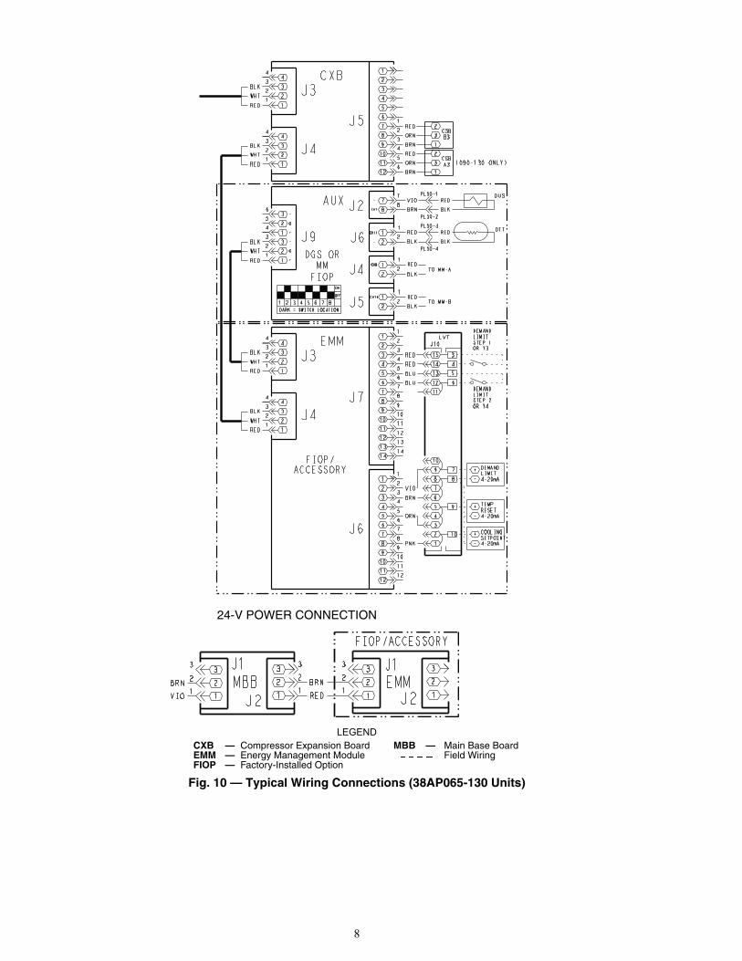
38AP065-130 UNITS WITH AUX BOARD — Performthe following procedure to install the harness and make thewiring connections. See Fig. 10 for wiring.
1. Disconnect the CXB connector J4 and plug it into theEMM connector J3.
2. Install the new harness 38APHLSLCE-A00 provided.a. Install plug labeled CXB-J4 to CXB-J4 and other
end labeled EMM-J4 to EMM-J4.
b. Install plug labeled CXB-J2 connector to CXB-J2and other end labeled EMM-J1 to EMM-J1.
c. Install plugs labeled EMM-J6 and J7 to EMM-J6and J7 and other end labeled LVT-J10 to LVT ter-minal strip.
38AP065-130 UNITS WITHOUT AUX BOARD — Per-form the following procedure to install the harness andmake the wiring connections. See Fig. 10 for wiring.Install the new harness 38APHLSLCE-A00 provided.
1. Install plug labeled CXB-J4 to CXB-J4 and other end la-beled EMM-J4 to EMM-J4.
2. Install plug labeled CXB-J2 connector to CXB-J2 andother end labeled EMM-J1 to EMM-J1.
3. Install plugs labeled EMM-J6 and J7 to EMM- J6 and J7and other end labeled LVT-J10 to LVT terminal strip.
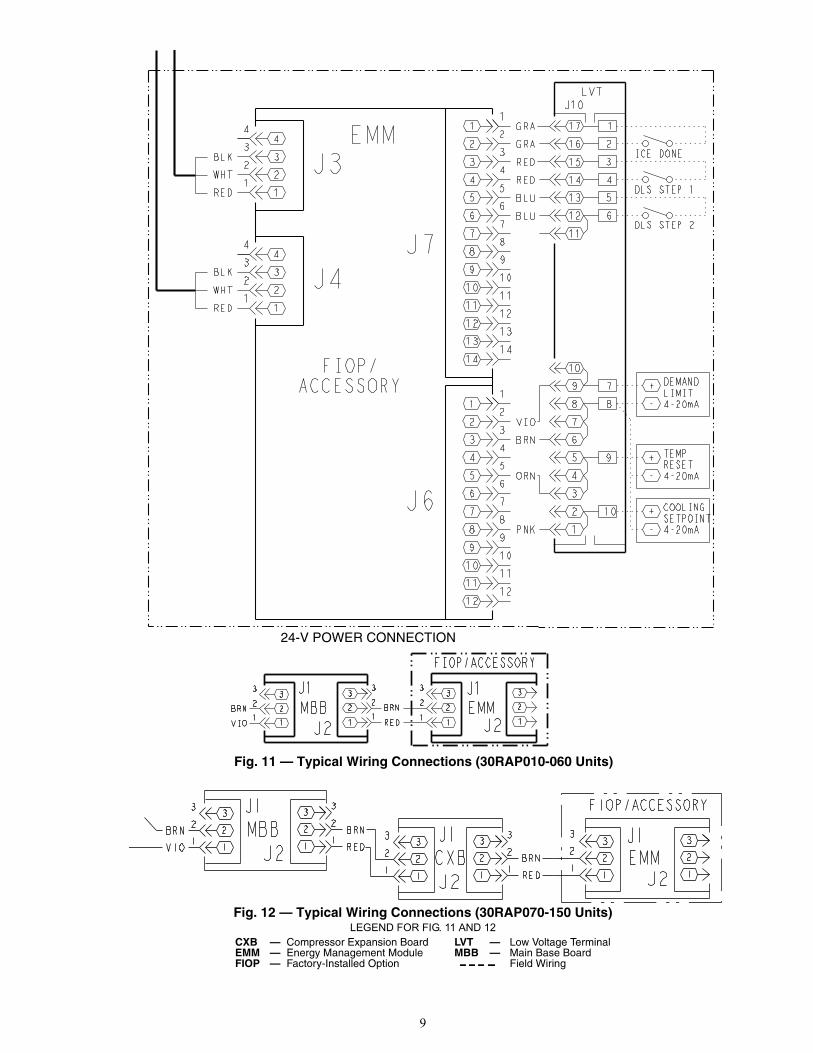
30RAP010-060 UNITS WITH AUX BOARD — Performthe following procedure to install the harness and make thewiring connections. See Fig. 11 for wiring.
1. Disconnect the EXV connector J4 and plug it into theEMM connector J4.
2. Install the new harness 38APHSCALECA00. Install pluglabeled EXV-J4 to EXV-J4 and other end labeled EMM-J3 to EMM-J3.
3. Install the new harness 38APHSCALECA10. DisconnectMBB connector J2 and plug it into the EMM-J2. Installplug labeled MBB/EXV-J2 to MBB-J2 and other end la-beled EMM-J1 to EMM-J1.
4. Install the new harness 38APHSCALE-A00. Install plugslabeled EMM-J6 and J7 to EMM-J6 and J7 and other endlabeled LVT-J10 to LVT terminal strip.
5. Install the new harness 38APHSCALXCA00 provided.Install plug labeled EMM-J3 to EMM-J3 and other endlabeled AUX-J9 to AUX-J9.
DISCONNECTOPTION CB1A/TB1A
TRAN1
FB1
CA1 CA2 CA3
CSB-A1 CSB-A2 CSB-A3
CCB-1 CCB-2 CCB-3
CCH
MBB
EMM
LVT
UPCUPC LONOPTIONTB3
OFF
ON
SW2
ENABLE
SW1
REMOTECONTROL
CB1 CB2 CB3
LOCATED OVER EMM
OFF
L1 L2 L3
12345678910111213141516171819202122232425
EQUIPGND
2 4 6
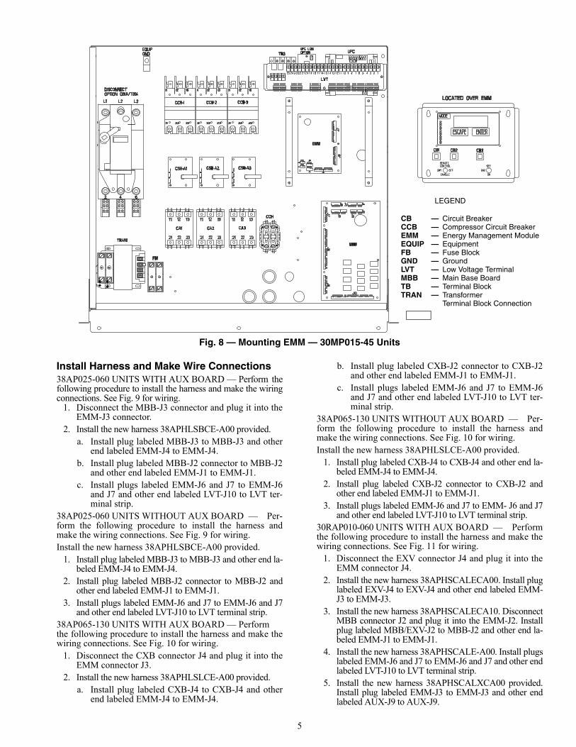
Fig. 8 — Mounting EMM — 30MP015-45 Units
LEGEND
CB — Circuit BreakerCCB — Compressor Circuit BreakerEMM — Energy Management ModuleEQUIP — EquipmentFB — Fuse BlockGND — GroundLVT — Low Voltage TerminalMBB — Main Base BoardTB — Terminal BlockTRAN — Transformer
Terminal Block Connection
a38-7210

6
30RAP010-060 UNITS WITHOUT AUX BOARD — Per-form the following procedure to install the harness andmake the wiring connections. See Fig. 11 for wiring.
1. Install the new harness 38APHSCALECA00. Installplug labeled EXV-J4 to EXV-J4 and other end labeledEMM-J3 to EMM-J3.
2. Install the new harness 38APHSCALECA10. Install pluglabeled MBB/EXV-J2 to MBB-J2 and other end labeledEMM-J1 to EMM-J1.
3. Install the new harness 38APHSCALE-A00. Install plugslabeled EMM-J6 and J7 to EMM-J6 and J7 and other endlabeled LVT-J10 to LVT terminal strip.
30RAP070-150 UNITS WITH AUX BOARD — Performthe following procedure to install the harness and make thewiring connections. See Fig. 12 for wiring.
1. Disconnect the CXB connector J4 and plug it into theEMM connector J4.
2. Install the new harness 38APHSCALECA00. Install pluglabeled EXV-J4 to CXB-J4 and other end labeled EMM-J3 to EMM-J3.
3. Install the new harness 38APHSCALECA10. Install pluglabeled MBB/EXV-J2 to CXB-J2 and other end labeledEMM-J1 to EMM-J1.
4. Install the new harness 38APHSCALE-A00. Install plugslabeled EMM-J6 and J7 to EMM-J6 and J7 and other endlabeled LVT-J10 to LVT terminal strip.
30RAP070-090 UNITS WITHOUT AUX BOARD — Per-form the following procedure to install the harness andmake the wiring connections. See Fig. 11 for wiring.
1. Install the new harness 38APHSCALECA00. Install theplug labeled EXV-J4 to CXB-J4 and other end labeledEMM-J3 to EMM-J3.
2. Install the new harness 38APHSCALECA10. Install pluglabeled MBB/EXV-J2 to CXB-J2 and other end labeledEMM-J1 to EMM-J1.
3. Install the new harness 38APHSCALE-A00. Install plugslabeled EMM-J6 and J7 to EMM-J6 and J7 and other endlabeled LVT-J10 to LVT terminal strip.
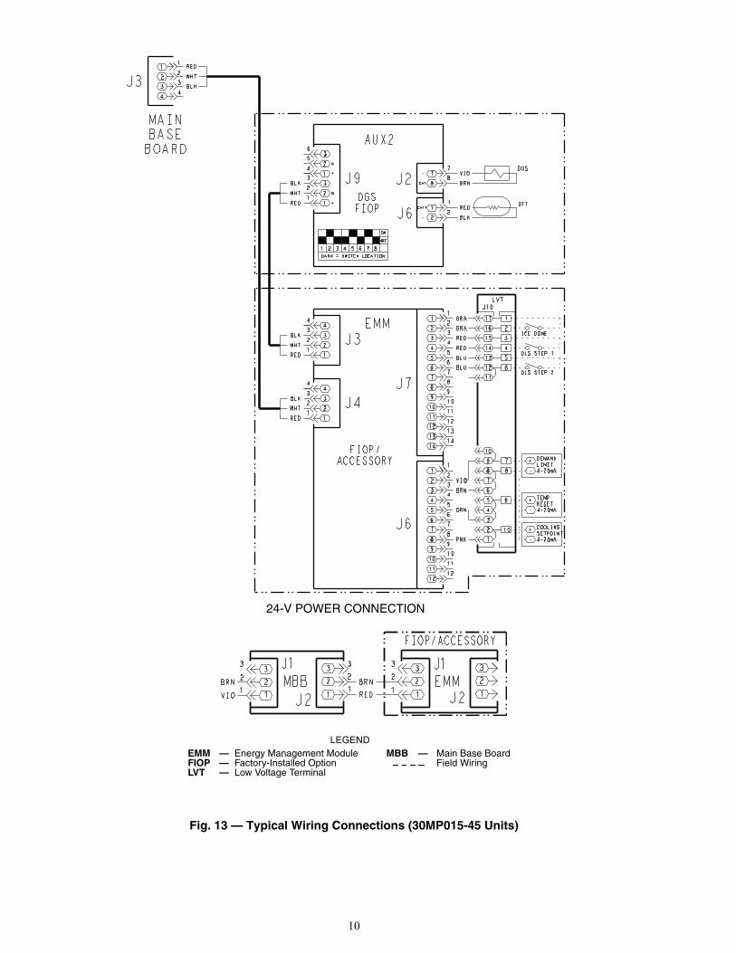
30MP015-045 UNITS WITH AUX BOARD — Performthe following procedure to install the harness and make thewiring connections. See Fig. 13 for wiring.
1. Disconnect the MBB connector J3 and plug it into theEMM connector J3.
2. Install the new harness 38APHSCALECA00. Install oneend of the harness in MBB connector J3 and the other endin EMM connector J4.
3. Install the new harness 38APHSCALECA10. Install pluglabeled MBB/EXV-J2 to MBB-J2 and other end labeledEMM-J1 to EMM-J1.
4. Install the new harness 38APHSCALE-A00. Install plugslabeled EMM-J6 and J7 to EMM-J6 and J7 and the otherend labeled LVT-J10 to J10 of the LVT terminal strip.
5. Install the new harness 38APHSCALXCA00 provided.Install plug labeled EMM-J3 to EMM-J3 and other endlabeled AUX-J9 to AUX-J9.
30MP015-045 UNITS WITHOUT AUX BOARD — Per-form the following procedure to install the harness andmake the wiring connections. See Fig. 13 for wiring.
1. Install the new harness 38APHSCALECA00. Installone end of the harness in MBB connector J3 and theother end in EMM connector J4.
2. Install the new harness 38APHSCALECA10. Install pluglabeled MBB/EXV-J2 to MBB-J2 and other end labeledEMM-J1 to EMM-J1.
3. Install the new harness 38APHSCALE-A00. Install plugslabeled EMM-J6 and J7 to EMM-J6 and J7 and the otherend labeled LVT-J10 to J10 of the LVT terminal strip.
FIELD WIRING CONNECTIONS — Refer to Fig. 9-13for field wiring interfaces with the LVT terminal strip.
Controls Configuration for EMM Options —Refer to the 38AP controls and troubleshooting manual forsplit system configuration of controls. Refer to the 30RAPcontrols and troubleshooting manual for Aquasnap® configu-ration of controls. Refer to the 30MP controls and trouble-shooting manual for configuration of controls.
7
FIOP/
ON
OFF
1 2 3 4 5 6 7 8DARK = SWITCH LOCATION
3
2
1
3
2
1
6
5
4
3
2
1
J9
RED
WHT
BLK
12
11
10
9
8
7
6
5
4
3
2
1
12
11
10
9
8
7
J7
EMM4
3
2
1
4
3
2
1
J3
4
3
2
1
4
3
2
1
J4
RED
WHT
BLK
RED
WHT
BLK
12
11
10
9
8
7
6
5
4
3
2
1
12
11
10
9
8
7J6
14
1314
13
ACCESSORY
LVT
1
1
2
3
4
5
6
1
2
3
4
5
6
14
15
4
3
12
13
6
5
10
11
7
8
9
8
6
7
4
5 9
2
3
10 +
-
COOLINGSETPOINT4-20mA
RED
RED
BLU
BLU
PNK
ORN
BRN
VIO
+
-
TEMPRESET4-20mA
+
-
DEMANDLIMIT4-20mA
DEMANDLIMITSTEP 1OR Y3
DEMANDLIMITSTEP 2OR Y4
DGS ORMM
FIOP
DUS
2
1
8
7
2
1
8
7
J2
J6DTT
VIO
BRN
RED
BLK
2
12
1RED
BLKJ4
CH1
-
CH11
-
CH9
-
2
12
1
J5CH10
-
TO MM-A
J10
AUX
LEGEND
Fig. 9 — Typical Wiring Connections (38AP025-060 Units)
EMM — Energy Management Module MBB — Main Base BoardFIOP — Factory-Installed Option Field WiringLVT — Low Voltage Terminal
a30-4943
A38-7212
33
22
11
J2BRN
VIO
22
1
J1
1
33
MBB BRN
RED
33
22
11
J22
J1
1
3
FIOP/ACCESSORY
EMM
24-V POWER CONNECTION
8
FIOP/
12
11
10
9
8
7
6
5
4
3
2
1
6
5
4
3
2
1J5
CXB4
3
2
1
4
3
2
1
J3
CSBB3
2
3
1
RED
ORN
BRN
CSBA3
2
3
1
RED
ORN
BRN
4
3
2
1
4
3
2
1
J4
RED
WHT
BLK
RED
WHT
BLK
ON
OFF
1 2 3 4 5 6 7 8DARK = SWITCH LOCATION
DUS
3
2
1
3
2
1
6
5
4
3
2
1
J9 2
1
8
7
2
1
8
7
J2
J6DTT
RED
WHT
BLK
DGS ORMM
FIOP
12
11
10
9
8
7
6
5
4
3
2
1
12
11
10
9
8
7
J7
EMM4
3
2
1
4
3
2
1
J3
4
3
2
1
4
3
2
1
J4
RED
WHT
BLK
RED
WHT
BLK
12
11
10
9
8
7
6
5
4
3
2
1
12
11
10
9
8
7J6
14
1314
13
ACCESSORY
LVT
1
1
2
3
4
5
6
1
2
3
4
5
6
14
15
4
3
12
13
6
5
10
11
7
8
9
8
6
7
4
5 9
2
3
10 +
-
COOLINGSETPOINT4-20mA
RED
RED
BLU
BLU
PNK
ORN
BRN
VIO
+
-
TEMPRESET4-20mA
+
-
DEMANDLIMIT4-20mA
DEMANDLIMITSTEP 1OR Y3
DEMANDLIMITSTEP 2OR Y4
VIO REDPL50-1
BRN BLK
PL50-2
RED REDPL50-3
BLK BLK
PL50-4
2
12
1RED
BLKJ4
CH1
-
CH11
-
CH9
-
-
+
G
-
+
G
2
12
1RED
BLKJ5CH10
-
TO MM-A
TO MM-B
(090-130 ONLY)
J10
AUX
LEGEND
Fig. 10 — Typical Wiring Connections (38AP065-130 Units)
CXB — Compressor Expansion Board MBB — Main Base BoardEMM — Energy Management Module Field WiringFIOP — Factory-Installed Option
a30-4944
A38-7212
33
22
11
J2BRN
VIO
22
1
J1
1
33
MBB BRN
RED
33
22
11
J22
J1
1
3
FIOP/ACCESSORY
EMM
24-V POWER CONNECTION
9
FIOP/
12
11
10
9
8
7
6
5
4
3
2
1
12
11
10
9
8
7
J7
EMM4
3
2
1
4
3
2
1
J3
4
3
2
1
4
3
2
1
J4
RED
WHT
BLK
RED
WHT
BLK
12
11
10
9
8
7
6
5
4
3
2
1
12
11
10
9
8
7J6
14
1314
13
ACCESSORY
1
1
2
3
4
5
6
1
2
3
4
5
6
10
7
8
9
8
6
7
4
5 9
2
3
10 +
-
COOLINGSETPOINT4-20mAPNK
ORN
BRN
VIO
+
-
TEMPRESET4-20mA
+
-
DEMANDLIMIT4-20mA
14
15
4
3
12
13
6
5
11
RED
RED
BLU
BLUDLS STEP 2
DLS STEP 1
LVT
16
17
2
1GRA
GRAICE DONE
J10
Fig. 11 — Typical Wiring Connections (30RAP010-060 Units)
a30-4945
A38-7212
33
22
11
J2BRN
VIO
22
1
J1
1
33
MBB BRN
RED
33
22
11
J22
J1
1
3
FIOP/ACCESSORY
EMM
24-V POWER CONNECTION
Fig. 12 — Typical Wiring Connections (30RAP070-150 Units)LEGEND FOR FIG. 11 AND 12
CXB — Compressor Expansion Board LVT — Low Voltage TerminalEMM — Energy Management Module MBB — Main Base BoardFIOP — Factory-Installed Option Field Wiring
10
Fig. 13 — Typical Wiring Connections (30MP015-45 Units)
MAINBASEBOARD
FIOP/
ON
OFF
1 2 3 4 5 6 7 8DARK = SWITCH LOCATION
DUS
3
2
1
3
2
1
6
5
4
3
2
1
J9
2
1
8
7
2
1
8
7
J2
J6DTTRED
WHT
BLK
DGS
12
11
10
9
8
7
6
5
4
3
2
1
12
11
10
9
8
7
J7
EMM4
3
2
1
4
3
2
1
J3
4
3
2
1
4
3
2
1
J4
RED
WHT
BLK
RED
WHT
BLK
12
11
10
9
8
7
6
5
4
3
2
1
12
11
10
9
8
7J6
14
1314
13
ACCESSORY
1
1
2
3
4
5
6
1
2
3
4
5
6
14
15
4
3
12
13
6
5
10
11
7
8
9
8
6
7
4
5 9
2
3
10 +
-
COOLINGSETPOINT4-20mA
RED
RED
BLU
BLU
PNK
ORN
BRN
VIO
+
-
TEMPRESET4-20mA
+
-
DEMANDLIMIT4-20mA
DLS STEP 2
VIO
BRN
RED
BLK
CH1
-
CH11
-
-
+
G
-
+
G
DLS STEP 1
LVT
16
17
2
1GRA
GRAICE DONE
3
44
32
21
1
BLK
WHT
RED
J3
FIOP
J10
AUX2
LEGENDEMM — Energy Management Module MBB — Main Base BoardFIOP — Factory-Installed Option Field WiringLVT — Low Voltage Terminal
A38-7212
A38-7211
33
22
11
J2BRN
VIO
22
1
J1
1
33
MBB BRN
RED
33
22
11
J22
J1
1
3
FIOP/ACCESSORY
EMM
24-V POWER CONNECTION


Manufacturer reserves the right to discontinue, or change at any time, specifications or designs without notice and without incurring obligations.Catalog No. 04-53300104-01 Printed in U.S.A. Form 30/38-11SI Pg 12 11-12 Replaces: 30/38-7SI
© Carrier Corporation 2012