Embed Size (px)
Citation preview
Products Solutions ServicesEA01060D/06/A2/02.1571303750
Installation Instructions
Replacing the DSC-Sensor and the S-DATProwirl 200
Instruction is valid for the following spare part kits:
NOTICE
‣ The order number of the spare part set (on the packaging label) can differ from the product number (on the label directly on the spare part)!
‣ The order number of the relevant spare part set can be established by entering the material number of the spare part in the spare parts finder.
‣ We recommend that the Installation Instructions be kept with the packaging at all times.
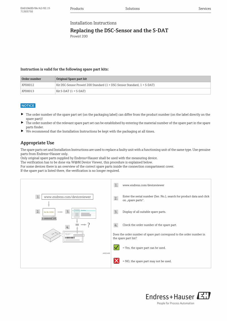
Appropriate UseThe spare parts set and Installation Instructions are used to replace a faulty unit with a functioning unit of the same type. Use genuine parts from Endress+Hauser only. Only original spare parts supplied by Endress+Hauser shall be used with the measuring device. The verification has to be done via W@M Device Viewer, this procedure is explained below.For some devices there is an overview of the correct spare parts inside the connection compartment cover.If the spare part is listed there, the verification is no longer required.
Order number Original Spare part kit
XPD0012 Kit DSC-Sensor Prowirl 200 Standard (1 × DSC-Sensor Standard, 1 × S-DAT)
XPD0013 Kit S-DAT (1 × S-DAT)
A0022408
www.endress.com/deviceviewer
Enter the serial number (Ser. No.), search for product data and click on „spare parts“.
Display of all suitable spare parts.
Check the order number of the spare part.
Does the order number of spare part correspond to the order number in the spare part list?
= Yes, the spare part can be used.
= NO, the spare part may not be used.
= ?
1.
Ser. No.:12345
www.endress.com/deviceviewer
2. 3.
4.
1.
2.
3.
4.
Replacing the DSC-Sensor and the S-DAT 01060
2 Endress+Hauser
Authorized personnel
NOTICE
The person who carries out the repair is responsible for safety during the work, the quality of work completed and safety of the device after repair.
Pressure test after sensor removal
NOTICE
After sensor removal a pressure test principally is recommended. The pressure test is required for devices which had been delivered with Option PED or a pressure test certificate.
Safety instructions • Check whether the spare part matches the identification label on
the measuring device, as explained on the first page.• The spare parts set and Installation Instructions are used to
replace a faulty unit with a functioning unit of the same type. Use genuine parts from Endress+Hauser only.
• In the case of Ex-certified measuring devices: Only open in a de-energized state (once a delay of 10 minutes has elapsed after switching off the power supply) or in environments which do not have a potentially explosive atmosphere.
• The measuring device is energized. Danger: Risk of electric shock! Open the measuring device in a de-energized state only.
• Before removing the device: set the process in a safe condition and purge the pipe of dangerous materials.
• Hot surfaces! Risk of injury! Before commencing work, allow the system and measuring device to cool down to a touchable temperature.
• In the case of measuring devices in custody transfer, the custody transfer status no longer applies once the lead seal has been removed.
• Comply with national regulations governing mounting, electrical installation, commissioning, maintenance and repair procedures.
• Requirements with regard to specialized technical staff for the mounting, electrical installation, commissioning, maintenance and repair of the measuring devices:
– trained in instrument safety– familiar with the individual operation conditions of the devices– for Ex-certified measuring devices: also trained in
explosion protection• Follow the Operating Instructions for the device.• Risk of damaging electronic components!
Ensure you have a working environment protected from electro-static discharge.
• After removing the electronics cover, there is a risk of electric shock as shock protection is removed! Switch off the measuring device before removing internal covers.
• Modifications to the measuring device are not permitted.• In the case of measuring devices in safety-related applications in
accordance with IEC 61508 or IEC 61511: After repair recommission in accordance with Operating Instructions. Document the repair procedure.
• Only open housing for a brief period. Avoid the penetration of foreign bodies, moisture or contaminants.
• Caution! When replacing amplifier boards, I/O boards or submo-dules, ensure compatibility with existing software. The process for reading out the software revision number is described in the Operating Instructions (device functions).If the software of the board is not compatible, it should be upda-ted using an operating software package (e.g. Field Care). In the event of functional changes, notify the plant owner/operator.
• Replace defective seal/gaskets with genuine parts from Endress+Hauser only.
• If threads are damaged or defective, the measuring device must be repaired.
• Threads (e.g. of the cover for the electronics and connection com-partments) must be lubricated. Use an acid-free, non-hardening grease if an abrasion resistant dry lubricant is non-existent.
• If spacing is reduced or the dielectric strength of the measuring device cannot be guaranteed during repair work, perform a test on completion of the work (e.g. high-voltage test in accordance with the manufacturer's instructions).
• Service connector: – do not connect in potentially explosive atmospheres.– only connect to Endress+Hauser service devices.
• Observe the instructions for transporting and returning the device outlined in the Operating Instructions.
• If you have any questions, contact your Endess+Hauser service organization.
Approval of the measuring device Group of persons authorized to carry out repairs
without approval 2, 3
with approval (for Ex. IECEx, ATEX, FM, CSA, TIIS, NEPSI) 2, 3
1 = Trained customer technician
2 = Service technician authorized by Endress+Hauser
3 = Endress+Hauser (send measuring device back to manufacturer)
01060 Replacing the DSC-Sensor and the S-DAT
Endress+Hauser 3
Important advice to the replacement of the sensor compact and remote version
DANGER!
1. The sealing surface must not get scratched.
2. Remove sealing disk using a suitable tool, without scratching the sealing surface.
3. Clean the sealing surface on the meter body using a suitable solvent and lint-free cloth.
4. The bore in which it sits must be completely clean.
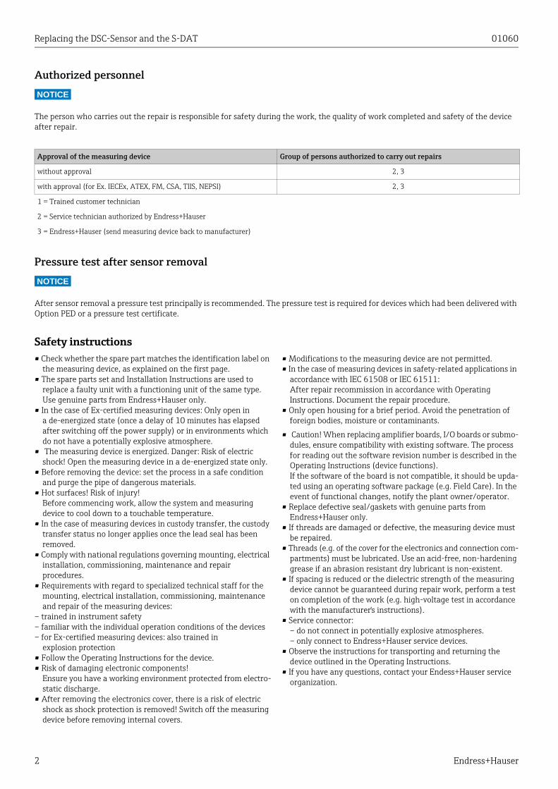
5. Place the new sensor seal on the sealing surface with the inscription (if present) facing upwards.
6. Apply grease to the thread and head contacts of the sensor screws.
7. Apply one drop of grease to both the thread and the connec-ting surfaces of the screws. The grease used must be suited to the application temperature range. The high-temperature paste HTP (50048898) is recommeded.
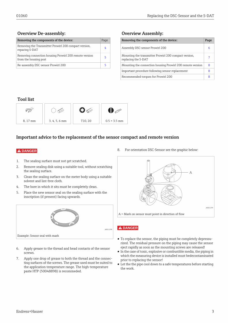
8. For orientation DSC-Sensor see the graphic below:
DANGER!
• To replace the sensor, the piping must be completely depressu-rized. The residual pressure on the piping may cause the sensor eject rapidly as soon as the mounting screws are released!
• In the case of toxic, explosive or combustible media, the piping in which the measuring device is installed must bedecontaminated prior to replacing the sensor!
• Let the the pipe cool down to a safe temperatures before starting the work.
Overview De-assembly: Overview Assembly:Removing the components of the device: Page Removing the components of the device: Page
Removing the Transmitter Prowirl 200 compact version, repacing S-DAT 4 Assembly DSC-sensor Prowirl 200 6
Removing connection housing Prowirl 200 remote version from the housing post
5 Mounting the transmitter Prowirl 200 compact version, replacing the S-DAT
7
Re-assembly DSC-sensor Prowirl 200 5 Mounting the connection housing Prowirl 200 remote version 8
Important procedure following sensor replacement 8
Recommended torques for Prowirl 200 8
Tool list
8, 17 mm 3, 4, 5, 6 mm T10, 20 0.5 × 3.5 mm
A0021298
Example: Sensor seal with mark
A0021299
A = Mark on sensor must point in direction of flow
A
Replacing the DSC-Sensor and the S-DAT 01060
4 Endress+Hauser
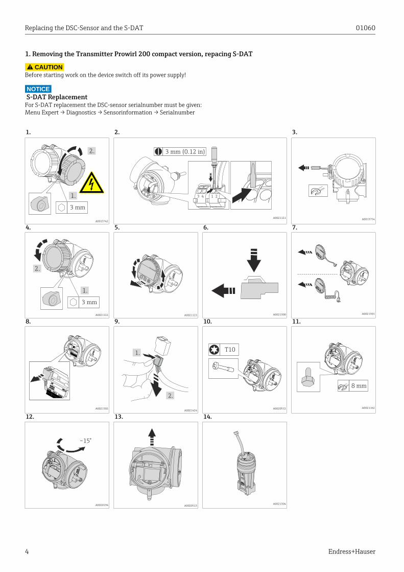
1. Removing the Transmitter Prowirl 200 compact version, repacing S-DAT
CAUTION!
Before starting work on the device switch off its power supply!
NOTICE S-DAT ReplacementFor S-DAT replacement the DSC-sensor serialnumber must be given:Menu Expert → Diagnostics → Sensorinformation → Serialnumber
1. 2. 3.
A0013742A0021121 A0013754
4. 5. 6. 7.
A0021122 A0021123 A0021300 A0021301
8. 9. 10. 11.
A0021302A0021424
A0020512 A0021162
12. 13. 14.
A0020194 A0020513A0021304
3 mm
1.
2. 3 mm (0.12 in)
213 4
3 mm
1.
2.–
+
E
EscEsc
1.
2.
T10
8 mm
~15°
01060 Replacing the DSC-Sensor and the S-DAT
Endress+Hauser 5
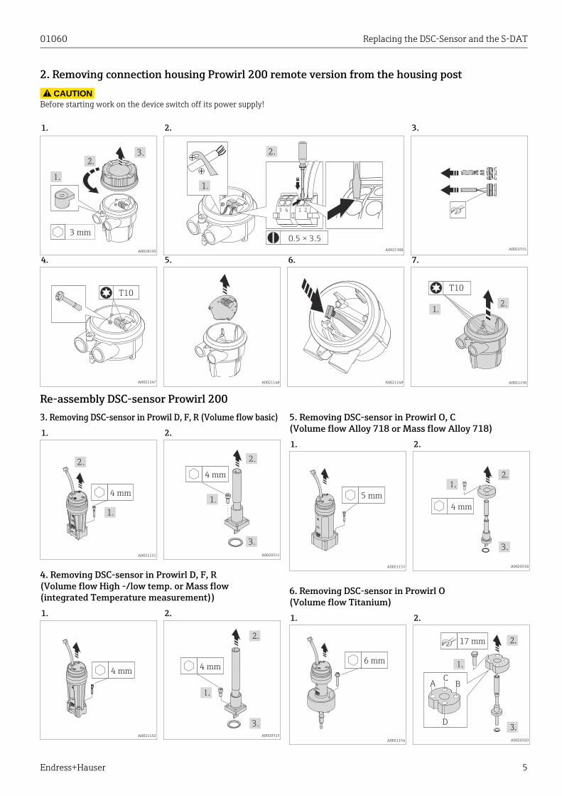
2. Removing connection housing Prowirl 200 remote version from the housing post
CAUTION!
Before starting work on the device switch off its power supply!
Re-assembly DSC-sensor Prowirl 2003. Removing DSC-sensor in Prowil D, F, R (Volume flow basic)
4. Removing DSC-sensor in Prowirl D, F, R (Volume flow High -/low temp. or Mass flow (integrated Temperature measurement))
5. Removing DSC-sensor in Prowirl O, C(Volume flow Alloy 718 or Mass flow Alloy 718)
6. Removing DSC-sensor in Prowirl O (Volume flow Titanium)
1. 2. 3.
A0018130 A0021308 A0021551
4. 5. 6. 7.
A0021147 A0021148 A0021149 A0021150
3 mm
3.
0.5 × 3.5
1.
2.
213 4
T10
1.2.
T10
1. 2.
A0021151 A0020311
1. 2.
A0021152 A0020315
4 mm
1.
2.
4 mm
1.
2.
3.
4 mm4 mm
3.
1. 2.
A0021153 A0020318
1. 2.
A0021154 A0020320
5 mm
4 mm
3.
6 mm
17 mm
AC
D
B
Replacing the DSC-Sensor and the S-DAT 01060
6 Endress+Hauser
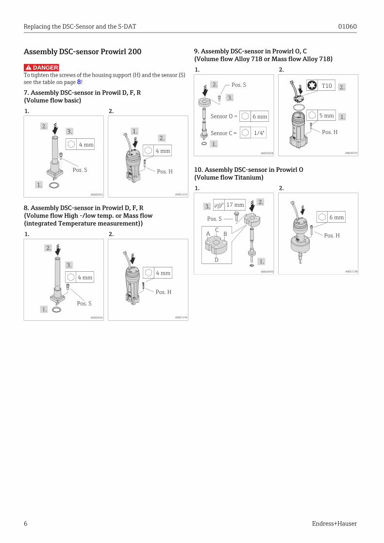
Assembly DSC-sensor Prowirl 200
DANGER!
To tighten the screws of the housing support (H) and the sensor (S) see the table on page 8!
7. Assembly DSC-sensor in Prowil D, F, R (Volume flow basic)
8. Assembly DSC-sensor in Prowirl D, F, R (Volume flow High -/low temp. or Mass flow (integrated Temperature measurement))
9. Assembly DSC-sensor in Prowirl O, C(Volume flow Alloy 718 or Mass flow Alloy 718)
10. Assembly DSC-sensor in Prowirl O (Volume flow Titanium)
1. 2.
A0020322 A0021155
1. 2.
A0020326 A0021156
4 mm
Pos. S
2.
1.
3.
4 mm
1.2.
Pos. H
Pos. S
4 mm
3.
4 mm
Pos. H
1. 2.
A0020328 A0020333
1. 2.
A0020330 A0021158
Pos. S
3.
1.
2.
6 mmSensor O =
Sensor C = 1/4"
2.
5 mm
T10
1.
Pos. H
Pos. S
17 mm
AC
D
B
6 mm
Pos. H
01060 Replacing the DSC-Sensor and the S-DAT
Endress+Hauser 7
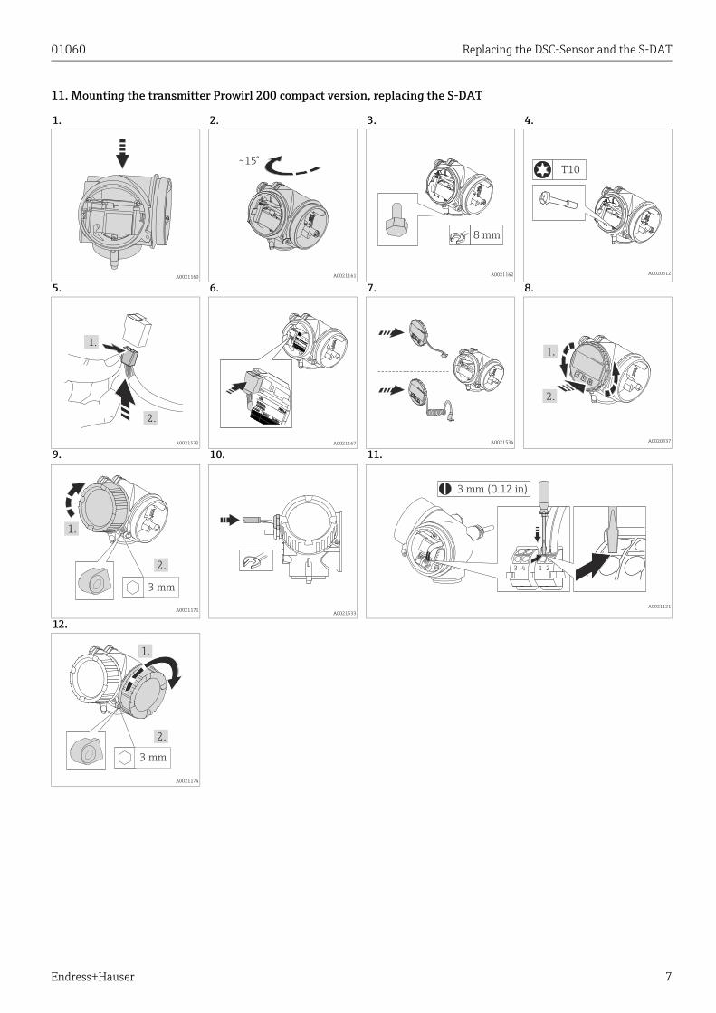
11. Mounting the transmitter Prowirl 200 compact version, replacing the S-DAT
1. 2. 3. 4.
A0021160 A0021161 A0021162 A0020512
5. 6. 7. 8.
A0021532 A0021167 A0021534 A0020337
9. 10. 11.
A0021171A0021533
A0021121
12.
A0021174
~15°
8 mm
T10
1.
2.
2.
–
+
E
EscEsc
3 mm
1.
2.
3 mm (0.12 in)
213 4
3 mm
1.
2.
Replacing the DSC-Sensor and the S-DAT 01060
8 Endress+Hauser
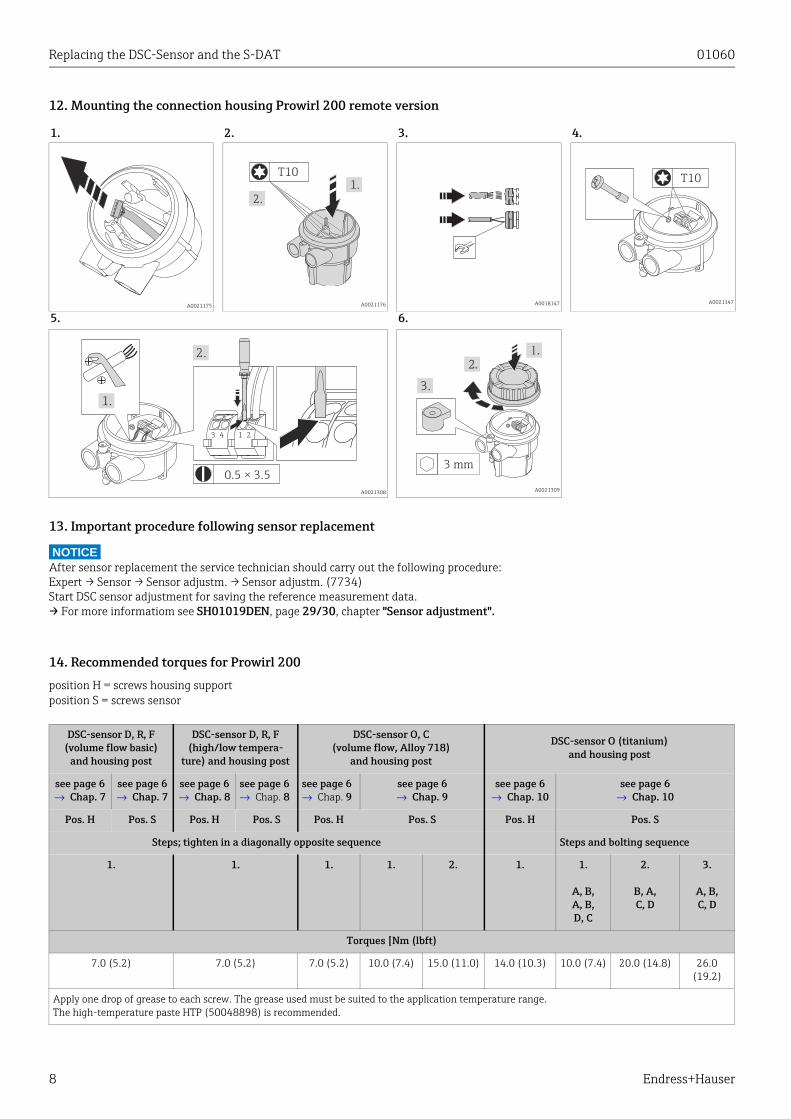
12. Mounting the connection housing Prowirl 200 remote version
13. Important procedure following sensor replacement
NOTICEAfter sensor replacement the service technician should carry out the following procedure: Expert → Sensor → Sensor adjustm. → Sensor adjustm. (7734)Start DSC sensor adjustment for saving the reference measurement data.→ For more informatiom see SH01019DEN, page 29/30, chapter "Sensor adjustment".
14. Recommended torques for Prowirl 200
position H = screws housing supportposition S = screws sensor
1. 2. 3. 4.
A0021175 A0021176 A0018147 A0021147
5. 6.
A0021308 A0021309
1.
2.
T10T10
0.5 × 3.5
1.
2.
213 4
3 mm
3.
DSC-sensor D, R, F(volume flow basic)
and housing post
DSC-sensor D, R, F (high/low tempera-
ture) and housing post
DSC-sensor O, C(volume flow, Alloy 718)
and housing post
DSC-sensor O (titanium)and housing post
see page 6→ Chap. 7
see page 6→ Chap. 7
see page 6→ Chap. 8
see page 6→ Chap. 8
see page 6→ Chap. 9
see page 6→ Chap. 9
see page 6→ Chap. 10
see page 6→ Chap. 10
Pos. H Pos. S Pos. H Pos. S Pos. H Pos. S Pos. H Pos. S
Steps; tighten in a diagonally opposite sequence Steps and bolting sequence
1. 1. 1. 1. 2. 1. 1.
A, B, A, B, D, C
2.
B, A,C, D
3.
A, B, C, D
Torques [Nm (lbft)
7.0 (5.2) 7.0 (5.2) 7.0 (5.2) 10.0 (7.4) 15.0 (11.0) 14.0 (10.3) 10.0 (7.4) 20.0 (14.8) 26.0 (19.2)
Apply one drop of grease to each screw. The grease used must be suited to the application temperature range.The high-temperature paste HTP (50048898) is recommended.

Products Solutions ServicesEA01060D/06/A2/02.1571303750
Einbauanleitung
Austausch DSC-Sensor und S-DATProwirl 200
Die Einbauanleitung ist für folgende Ersatzteilsets gültig:
HINWEIS
‣ Die Bestellnummer des Ersatzteilsets (auf dem Produktaufkleber der Verpackung) kann sich von der Produktionsnummer (auf dem Aufkleber direkt auf dem Ersatzteil) unterscheiden!
‣ Durch Eingabe der Produktionsnummer des Ersatzteiles im Ersatzteilfindetool kann die Bestellnummer des ensprechenden Ersatzteilsets ermittelt werden.
‣ Wir empfehlen Einbauanleitung und Verpackung immer zusammen aufzubewahren.
Bestimmungsgemäße VerwendungErsatzteilset und Einbauanleitung dienen dazu, eine defekte Einheit gegen eine funktionierende Einheit des gleichen Typs zu ersetzen. Es dürfen nur Originalteile von Endress+Hauser verwendet werden.Grundsätzlich dürfen nur Ersatzteilsets verwendet werden, die von Endress+Hauser für das Messgerät vorgesehen sind.Die Überprüfung ist via W@M Device Viewer durchzuführen, die Vorgehensweise ist nachfolgend beschrieben.Bei einigen Messgeräten befindet sich im Anschlussraumdeckel eine Übersicht der passenden Ersatzteile.Ist dieses Ersatzteil dort aufgelistet, entfällt die Überprüfung.
Bestellnummer Original Ersatzteilset
XPD0012– Set DSC-Sensor Prowirl 200 Standard (1 × Dichtung, 1 × S-DAT)
XPD0013– Set S-DAT (1 × S-DAT)
A0022408
www.endress.com/deviceviewer
Seriennummer (Ser. No.) eingeben, Produktdaten suchen und auf "Ersatzteile" klicken.
Anzeige aller Ersatzteile zum Messgerät.
Bestellnummer des Ersatzteilsets ermitteln.
Stimmt die Bestellnummer auf dem Produktaufkleber mit der Bestell-nummer in der Ersatzteilliste überein?
= JA, das Ersatzteilset darf für das Messgerät verwendet werden.
= NEIN, das Ersatzteilset darf für das Messgerät nicht verwendet werden.
= ?
1.
Ser. No.:12345
www.endress.com/deviceviewer
2. 3.
4.
1.
2.
3.
4.
Austausch DSC-Sensor und S-DAT 01060
2 Endress+Hauser
Reparaturberechtigte Personen
HINWEIS
Die Person, die eine Reparatur vornimmt, übernimmt die Verantwortung für die Sicherheit während der Arbeiten, die Qualität der Ausführung und die Sicherheit des Geräts nach der Reparatur.
Drucktest nach Sensoraustausch
HINWEIS
Drucktest nach Sensortausch grundsätzlich empfohlen. Erforderlich ist der Drucktest für Geräte, welche mit Option PEDoder Drucktestzertifikat geliefert wurden.
Sicherheitshinweise • Prüfen, ob das vorliegende Ersatzteil zur Kennzeichnung auf
dem Messgerät passt, wie auf der Titelseite beschrieben.• Ersatzteilset und Einbauanleitung dienen dazu, eine defekte
Einheit gegen eine funktionierende Einheit des gleichen Typs zu ersetzen. Nur Originalteile von Endress+Hauser verwenden.
• Bei Ex-zertifizierten Messgeräten: Nur in spannungslosem Zustand (nach Berücksichtigung einer Wartezeit von 10 Minuten nach Abschalten der Energiezufuhr) oder in Umgebungen öffnen, die keine explosionsfähige Atmosphäre enthalten.
• Messgerät unter Spannung! Lebensgefahr durch Stromschlag. Messgerät nur im spannungslosen Zustand öffnen.
• Vor einem Geräteausbau: Prozess in sicheren Zustand bringen und Leitung von gefährlichen Prozessstoffen befreien.
• Verbrennungsgefahr durch heiße Oberflächen! Vor Arbeitsbeginn: Anlage und Messgerät auf berührungs-sichere Temperatur abkühlen.
• Bei Messgeräten im abrechnungspflichtigen Verkehr: Nach Entfernen der Plombe ist der geeichte Zustand aufgehoben.
• Nationale Vorschriften bezüglich der Montage, elektrischen Installation, Inbetriebnahme, Wartung und Reparatur einhalten.
• Folgende Anforderungen an das Fachpersonal für Montage, elektrische Installation, Inbetriebnahme, Wartung und Reparatur der Messgeräte müssen erfüllt sein:–In Gerätesicherheit ausgebildet–Mit den jeweiligen Einsatzbedingungen der Geräte vertraut–Bei Ex-zertifizierten Messgeräten zusätzlich im
Explosionsschutz ausgebildet• Die Betriebsanleitung zum Messgerät ist zu beachten.• Beschädigungsgefahr elektronischer Bauteile!
Eine ESD-geschützte Arbeitsumgebung herstellen.• Nach Entfernen der Elektronikabdeckung: Stromchlaggefahr
durch aufgehobenen Beruhrüngsschutz! Messgerät ausschalten, bevor interne Abdeckungen entfernt werden
• Änderungen am Messgerät sind nicht zulässig.• Bei Messgeräten in sicherheitstechnischen Applikationen
gemäß IEC 61508 bzw. IEC 61511: Nach Reparatur Neuinbetriebnahme gemäß Betriebsanleitung durchführen. Reparatur dokumentieren.
• Gehäuse nur kurzzeitig öffnen. Eindringen von Fremdkörpern, Feuchtigkeit oder Verunreinigung vermeiden.
• Achtung! Beim Auswechseln von Messverstärker-, I/O-Platine oder Submodulen: Kompatibilität mit der vorhandenen Software sicherstellen. Der Auslesevorgang der Software Revisionsnummer ist in der Betriebsanleitung (Geräte-funktionen) beschrieben. Wenn die Software der Platine nicht kompatibel ist, muss mit Hilfe einer Bediensoftware (z. B. Field Care) ein Update durchgeführt werden. Bei funktionalen Änderungen Anlagenbetreiber informieren.
• Defekte Dichtungen nur durch Original-Dichtungen von Endress+Hauser ersetzen.
• Defekte Gewinde erfordern eine Instandsetzung des Messgeräts.• Gewinde (z. B. von Elektronikraum-und Anschlussraumdeckel)
müssen geschmiert sein. Säurefreies, nicht härtendes Fett verwenden, sofern keine abriebfeste Trockenschmierung vorhanden ist.
• Wenn bei den Reparaturarbeiten Abstände reduziert oder die Spannungsfestigkeit des Messgeräts nicht sichergestellt werden kann: Prüfung nach Abschluss der Arbeiten durchführen (z.B. Hochspannungstest gemäß Herstellerangaben).
• Servicestecker: – nicht in explosionsfähiger Atmosphäre anschließen.– nur an Servicegeräte von Endress+Hauser anschließen.
• Die in der Betriebsanleitung aufgeführten Hinweise zum Transport und zur Rücksendung beachten.
• Bei Fragen kontaktieren Sie bitte Ihre zuständige Endress+Hauser Serviceorganisation.
Zulassung des Messgeräts Reparaturberechtigter Personenkreis
ohne Zulassung 2, 3
mit Zulassung (z.B. IECEx, ATEX, FM, CSA, TIIS, NEPSI) 2, 3
1 = Ausgebildete Fachkraft des Kunden
2 = Von Endress+Hauser autorisierter Servietechniker
3 = Endress+Hauser (Messgerät an Hersteller zurücksenden)
01060 Austausch DSC-Sensor und S-DAT
Endress+Hauser 3
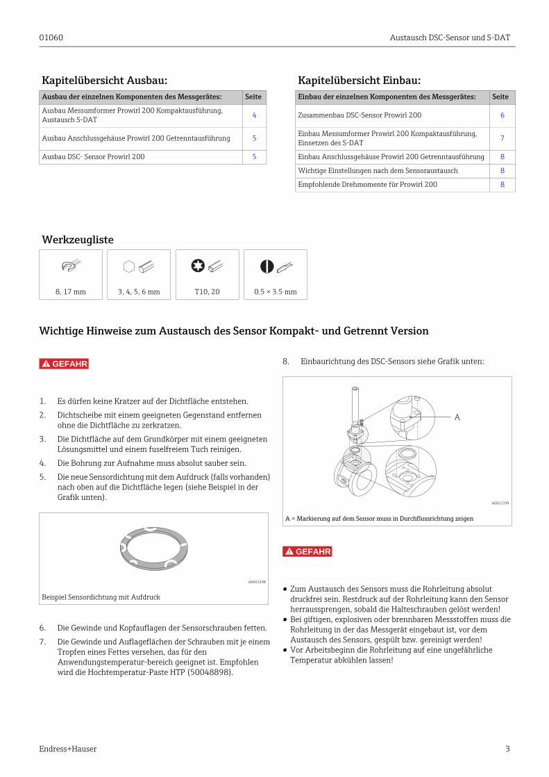
Wichtige Hinweise zum Austausch des Sensor Kompakt- und Getrennt Version
GEFAHR!
1. Es dürfen keine Kratzer auf der Dichtfläche entstehen.
2. Dichtscheibe mit einem geeigneten Gegenstand entfernen ohne die Dichtfläche zu zerkratzen.
3. Die Dichtfläche auf dem Grundkörper mit einem geeigneten Lösungsmittel und einem fuselfreiem Tuch reinigen.
4. Die Bohrung zur Aufnahme muss absolut sauber sein.
5. Die neue Sensordichtung mit dem Aufdruck (falls vorhanden) nach oben auf die Dichtfläche legen (siehe Beispiel in der Grafik unten).
6. Die Gewinde und Kopfauflagen der Sensorschrauben fetten.
7. Die Gewinde und Auflageflächen der Schrauben mit je einem Tropfen eines Fettes versehen, das für den Anwendungstemperatur-bereich geeignet ist. Empfohlen wird die Hochtemperatur-Paste HTP (50048898).
8. Einbaurichtung des DSC-Sensors siehe Grafik unten:
GEFAHR!
• Zum Austausch des Sensors muss die Rohrleitung absolut druckfrei sein. Restdruck auf der Rohrleitung kann den Sensor herraussprengen, sobald die Halteschrauben gelöst werden!
• Bei giftigen, explosiven oder brennbaren Messstoffen muss die Rohrleitung in der das Messgerät eingebaut ist, vor dem Austausch des Sensors, gespült bzw. gereinigt werden!
• Vor Arbeitsbeginn die Rohrleitung auf eine ungefährliche Temperatur abkühlen lassen!
Kapitelübersicht Ausbau: Kapitelübersicht Einbau:Ausbau der einzelnen Komponenten des Messgerätes: Seite Einbau der einzelnen Komponenten des Messgerätes: Seite
Ausbau Messumformer Prowirl 200 Kompaktausführung, Austausch S-DAT 4 Zusammenbau DSC-Sensor Prowirl 200 6
Ausbau Anschlussgehäuse Prowirl 200 Getrenntausführung 5 Einbau Messumformer Prowirl 200 Kompaktausführung, Einsetzen des S-DAT
7
Ausbau DSC- Sensor Prowirl 200 5 Einbau Anschlussgehäuse Prowirl 200 Getrenntausführung 8
Wichtige Einstellungen nach dem Sensoraustausch 8
Empfohlende Drehmomente für Prowirl 200 8
Werkzeugliste
8, 17 mm 3, 4, 5, 6 mm T10, 20 0.5 × 3.5 mm
A0021298
Beispiel Sensordichtung mit Aufdruck
A0021299
A = Markierung auf dem Sensor muss in Durchflussrichtung zeigen
A
Austausch DSC-Sensor und S-DAT 01060
4 Endress+Hauser
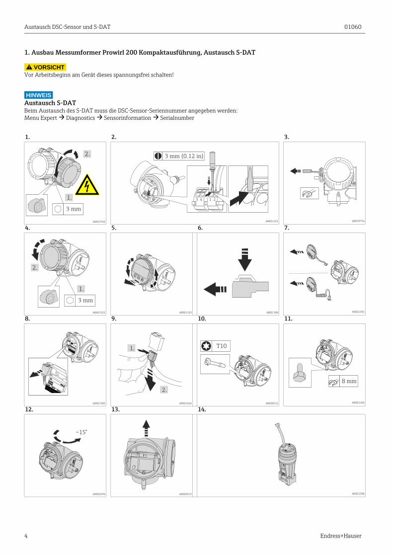
1. Ausbau Messumformer Prowirl 200 Kompaktausführung, Austausch S-DAT
VORSICHT!
Vor Arbeitsbeginn am Gerät dieses spannungsfrei schalten!
HINWEISAustausch S-DATBeim Austausch des S-DAT muss die DSC-Sensor-Seriennummer angegeben werden:Menu Expert → Diagnostics → Sensorinformation → Serialnumber
1. 2. 3.
A0013742 A0021121 A0013754
4. 5. 6. 7.
A0021122 A0021123 A002.300 A0021301
8. 9. 10. 11.
A0021302 A0021424 A0020512 A0021162
12. 13. 14.
A0020194 A0020513 A0021304
3 mm
1.
2. 3 mm (0.12 in)
213 4
3 mm
1.
2.–
+
E
EscEsc
1.
2.
T10
8 mm
~15°
01060 Austausch DSC-Sensor und S-DAT
Endress+Hauser 5
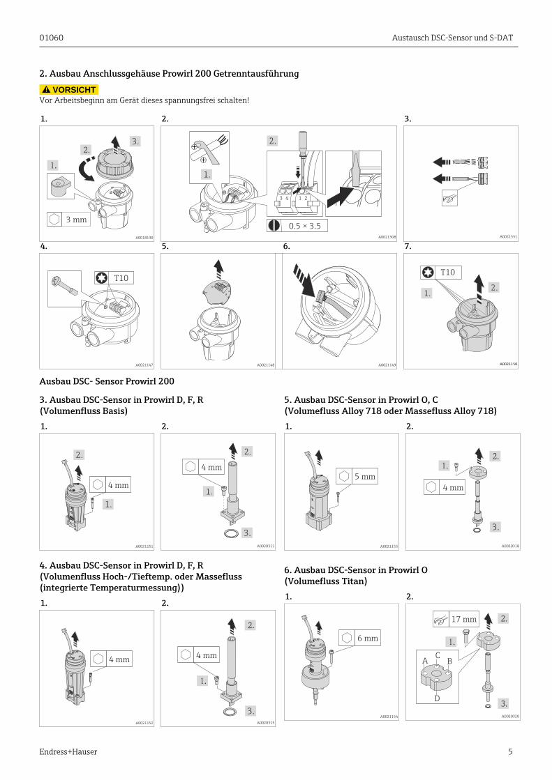
2. Ausbau Anschlussgehäuse Prowirl 200 Getrenntausführung
VORSICHT!
Vor Arbeitsbeginn am Gerät dieses spannungsfrei schalten!
Ausbau DSC- Sensor Prowirl 200
3. Ausbau DSC-Sensor in Prowirl D, F, R (Volumenfluss Basis)
4. Ausbau DSC-Sensor in Prowirl D, F, R (Volumenfluss Hoch-/Tieftemp. oder Massefluss (integrierte Temperaturmessung))
5. Ausbau DSC-Sensor in Prowirl O, C(Volumefluss Alloy 718 oder Massefluss Alloy 718)
6. Ausbau DSC-Sensor in Prowirl O (Volumefluss Titan)
1. 2. 3.
A0018130 A0021308 A0021551
4. 5. 6. 7.
A0021147 A0021148 A0021149 A0021150
3 mm
3.
0.5 × 3.5
1.
2.
213 4
T10
1.2.
T10
1. 2.
A0021151 A0020311
1. 2.
A0021152 A0020315
4 mm
1.
2.
4 mm
1.
2.
3.
4 mm4 mm
3.
1. 2.
A0021153 A0020318
1. 2.
A0021154 A0020320
5 mm
4 mm
3.
6 mm
17 mm
AC
D
B
Austausch DSC-Sensor und S-DAT 01060
6 Endress+Hauser
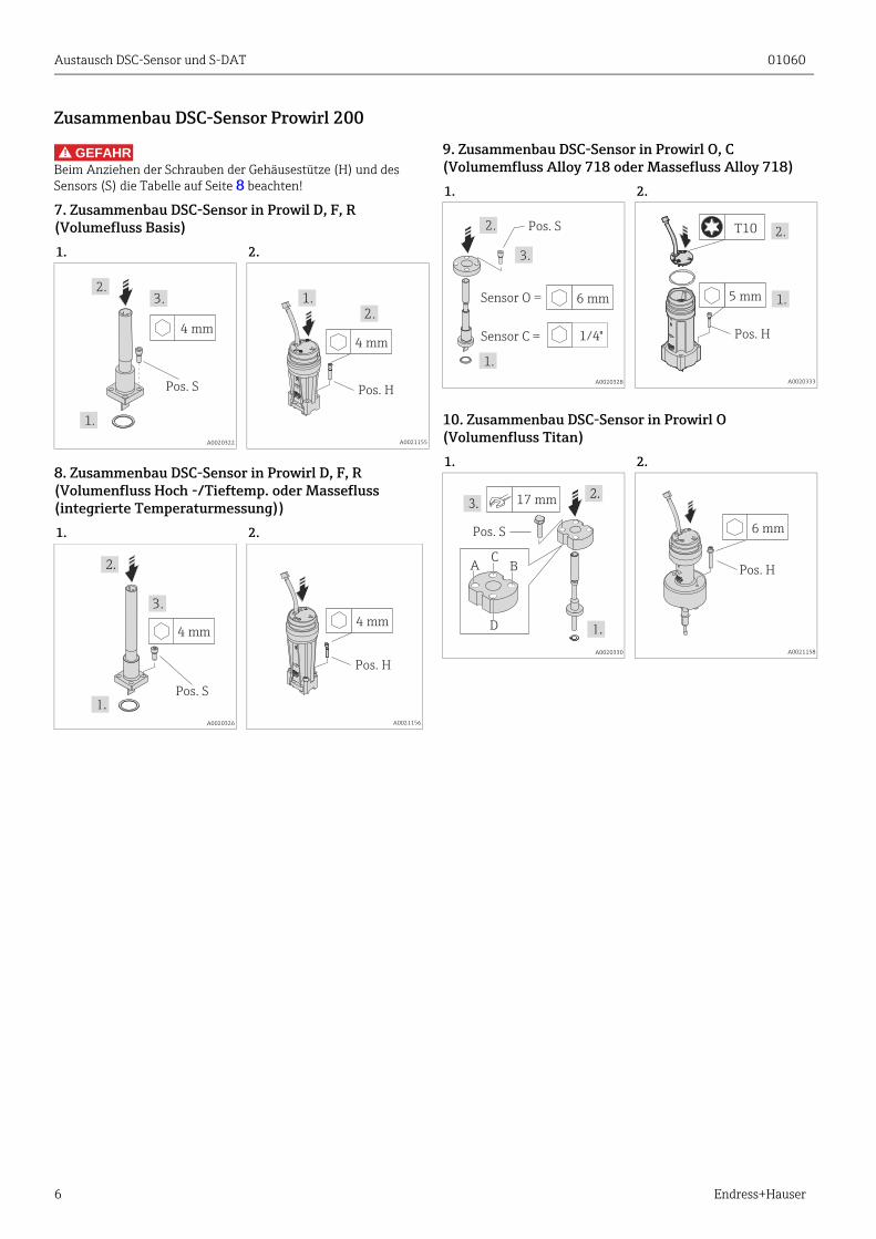
Zusammenbau DSC-Sensor Prowirl 200
GEFAHR!
Beim Anziehen der Schrauben der Gehäusestütze (H) und des Sensors (S) die Tabelle auf Seite 8 beachten!
7. Zusammenbau DSC-Sensor in Prowil D, F, R (Volumefluss Basis)
8. Zusammenbau DSC-Sensor in Prowirl D, F, R (Volumenfluss Hoch -/Tieftemp. oder Massefluss (integrierte Temperaturmessung))
9. Zusammenbau DSC-Sensor in Prowirl O, C(Volumemfluss Alloy 718 oder Massefluss Alloy 718)
10. Zusammenbau DSC-Sensor in Prowirl O (Volumenfluss Titan)
1. 2.
A0020322 A0021155
1. 2.
A0020326 A0021156
4 mm
Pos. S
2.
1.
3.
4 mm
1.2.
Pos. H
Pos. S
4 mm
3.
4 mm
Pos. H
1. 2.
A0020328 A0020333
1. 2.
A0020330 A0021158
Pos. S
3.
1.
2.
6 mmSensor O =
Sensor C = 1/4"
2.
5 mm
T10
1.
Pos. H
Pos. S
17 mm
AC
D
B
6 mm
Pos. H
01060 Austausch DSC-Sensor und S-DAT
Endress+Hauser 7
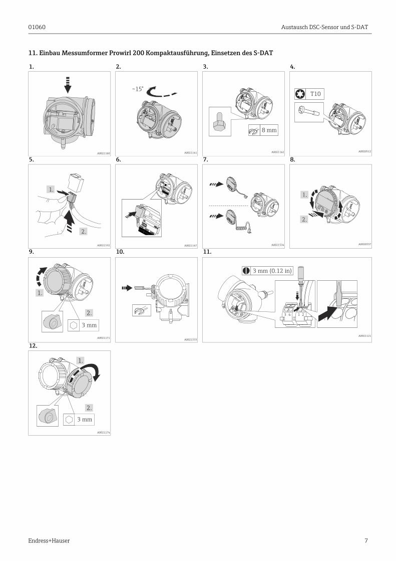
11. Einbau Messumformer Prowirl 200 Kompaktausführung, Einsetzen des S-DAT
1. 2. 3. 4.
A0021160 A0021161 A0021162 A0020512
5. 6. 7. 8.
A0021532 A0021167 A0021534 A0020337
9. 10. 11.
A0021171A0021533
A0021121
12.
A0021174
~15°
8 mm
T10
1.
2.
2.
–
+
E
EscEsc
3 mm
1.
2.
3 mm (0.12 in)
213 4
3 mm
1.
2.
Austausch DSC-Sensor und S-DAT 01060
8 Endress+Hauser
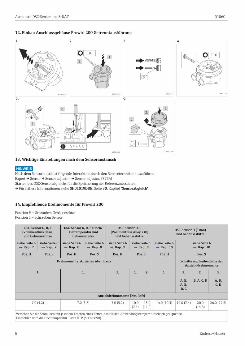
12. Einbau Anschlussgehäuse Prowirl 200 Getrenntausführung
13. Wichtige Einstellungen nach dem Sensoraustausch
HINWEISNach dem Sensortausch ist folgende Interaktion durch den Servicetechniker auszuführen: Expert → Sensor → Sensor adjustm. → Sensor adjustm. (7734)Starten des DSC-Sensorabgleichs für die Speicherung der Referenzmessdaten. → Für nähere Informationen siehe SH01019DDE, Seite 30, Kapitel "Sensorabgleich".
14. Empfohlende Drehmomente für Prowirl 200
Position H = Schrauben GehäusestützePosition S = Schrauben Sensor
1. 2. 3. 4.
A0021175 A0021176 A0018147 A0021147
5. 6.
A0021308 A0021309
1.
2.
T10T10
0.5 × 3.5
1.
2.
213 4
3 mm
3.
DSC-Sensor D, R, F(Volumenfluss Basis)
und Gehäusestütze
DSC-Sensor D, R, F (Hoch/Tieftemperatur und
Gehäusestütze
DSC-Sensor O, C(Volumenfluss Alloy 718)
und Gehäusestütze
DSC-Sensor O (Titan)und Gehäusestütze
siehe Seite 6→ Kap. 7
siehe Seite 6→ Kap. 7
siehe Seite 6→ Kap. 8
siehe Seite 6→ Kap. 8
siehe Seite 6→ Kap. 9
siehe Seite 6→ Kap. 9
siehe Seite 6→ Kap. 10
siehe Seite 6→ Kap. 10
Pos. H Pos. S Pos. H Pos. S Pos. H Pos. S Pos. H Pos. S
Drehmomente; Anziehen über Kreuz Schritte und Reihenfolge der Anziehddrehmomente
1. 1. 1. 1. 2. 1. 1.
A, B, A, B, D, C
2.
B, A, C, D
3.
A, B, C, D
Anziehdrehmomente [Nm (lbft)
7,0 (5,2) 7,0 (5,2) 7,0 (5,2) 10,0 (7,4)
15,0 (11,0)
14,0 (10,3) 10,0 (7,4) 20,0 (14,8)
26,0 (19,2)
Versehen Sie die Schrauben mit je einem Tropfen eines Fettes, das für den Anwendungstemperaturbereich geeignet ist.Empfohlen wird die Hochtemperatur-Paste HTP (50048898).