Embed Size (px)
Citation preview

6747 Whitestone Road • Baltimore, MD 21207 • (410) 298-4343 • FAX: (410) 298-3579www.atiracing.com
Installation Instructions
SUPER SERVOPart # 205327
Before you begin: If your Powerglide transmission is assembled, you must remove the pump from the unit. Otherwise, the transmission pan and valve body need to be removed if you can not remove the pump.
1. Remove the existing servo. Use a pair of needle nose pliers to hold the band adjustment strut. If this strut falls into the transmission, you will need to remove the valve body and the pan. (Refer to photos 1, 2 and 3.)
2. Removethecoverandexistingservo.Oilwillflowfromthetransmissionsobereadyforasmallmess.(Refer to photos 4, 5 and 6.)
3. Next, it is very important to make sure the “band apply hole” inside case is not sharp because it will damage the o-ring on new servo. (Photo 7.)
4. Check to be sure 2 - #145 and 2 - #016 o-rings are already installed on your new Super Servo Housing Body.
5. Put the new gasket onto the servo body and coat the o-ring with ATF. Be sure to lube the o-rings with ATF before installation! (Photo 8, 9 and 10.)
6. Hold the servo in place without installing to be sure the bolt holes and gasket will align when you install the servo into the case.
7. Using the .003 shim supplied with servo, cover the band apply hole with the shim, leaving enough shim out of the case to pull out after servo is installed . Failure to use shim will damage “O” ring when installing servo! Slide servo into the case, making sure the band apply hole is covered with the shim. When the Super Servo Housing is almost all the way against case, pull shim straight out with a pair of pliers. Use caution not to break shim! (Photos 11 and 12.)
8. Install and tighten 3 bolts (p/n 951012) into case. Note that they have a gasket under the head and be sure to tighten to 25 ft/lbs.
9. Put a small amount of grease in the 6 small counter bores for the #10 o-rings to help hold them in place during ring installation. Install six #10 o-rings in the housing. (Photo 13.)
10. Be sure “O” ring #156 is installed in bore of servo. Apply light coat of ATF to ring. Install sleeve (p/n 205331) into bore. There is a large Chamfer on the side this is to be installed into bore. Use 2 screws to pass through sleeve and into house to make sure you have the holes lined up for future steps.(Photos 14 and 15.)
11. Install (p/n 205333) spring cup onto piston and rod assembly. Large side of cup goes against piston. Install spring on rod, spring should slide over and locate on guide. Next, put ATF on piston rings and steel shaft that will pass through Super Servo BodyandTeflonO-rings.(Alreadyinstalledonpiston).(Photo 16.)
12. Install piston into servo, being sure to line up rod with the band strut. Take care not to damage rings when installing piston. You will need to have the Rod “grab” the strut as you push or lightly tap piston into place. Reference back to Photo 1 and 2 for strut install. (Photo 17.)
13. Be sure “O” ring #234 on outside cover. Photo 7 Lube “O” ring with ATF. Using 2 bolts (p/n 951176) and washers (p/n 953040) in cover to help align holes. Install cover to servo. When all 6 bolts are installed tighten with #25 torques bit. (Photos 18 and 19.)
14. You must Re-Adjust your Band!! Using an Inch / Lb Torque wrench tighten the rod to 72 in/lbs. Now turn the rod back out 4 turns. (Photo 20.)
15. Make sure pressure plug in cover is tight.
NOTE:Iftheservoisremovedforanyreason,thefirsto-ringmustbereplaced,asitwillbedamaged by the band apply hole. (Servo is shipped with 1 extra o-ring).

Photo 1
Photo 3
Photo 2
Photo 4
Photo 6Photo 5
Page 2
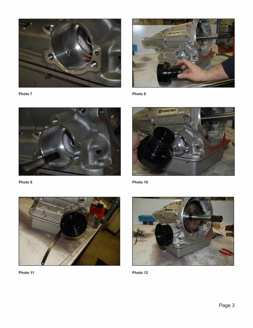
Photo 7 Photo 8
Photo 9 Photo 10
Photo 11 Photo 12
Page 3

Photo 13 Photo 14
Photo 15 Photo 16
Photo 17 Photo 18
Page 4

Photo 19 Photo 20
Page 5
See diagram on the following page for more information.

INST. #205327i 5/2009 Page 6