Embed Size (px)
Citation preview
HAYMAN REESE PART No: 21349
INSTALLATION INSTRUCTIONS
PLEASE ENSURE THAT INSTRUCTIONS ARE UNDERSTOOD PRIOR TO FITMENT
PLACE THESE INSTRUCTIONS IN THE VEHICLE’S GLOVEBOX AFTER INSTALLATION IS COMPLETED
Rev: A Page 1 Issue Date: 30-08-2016
Hayman Reese (Cequent) PO Box 4050, Dandenong South VIC 3164 Phone 1800 812 017 Email [email protected]
Warning:
1. Do not, drill, cut, weld or otherwise modify the towbar.
General: 1. Ensure all hardware items have been included refer to assembly diagram. 2. Be wary of any changes to vehicle designs or other accessories that may conflict with the installation of this
product. 3. TBM kit compliance plate sticker provided with this product shall be located on towbar adjacent to towbar
compliance plate sticker. 4. TBM kit load rating sticker provided with this product shall be conspicuously located on inside rear end of the
driver's door. (See diagram below). 5. Hayman Reese recommends that you check your tow ball to ensure that it complies with the Australian
standards AS 4177.2. 6. PLEASE NOTE: It is advised to remove your LUG or TBM when not towing so as to produce a clear view of the
vehicles registration plate if obscured, and to also provide maximum available departure angle.
Tow bar Maintenance and Care. We recommended to remove Tow Ball Mounts (TBM’s, tongues or lugs) when not being used for any considerable length of time. So as to avoid injury, when not towing it is suggested that the tongue, Pull Pin and R-clip are removed then stored in a safe, clean and dry place, away from excessive moisture. Hitch Pull Pins and spring “R” clips are regularly checked for proper installation. Replace any worn or defective parts.
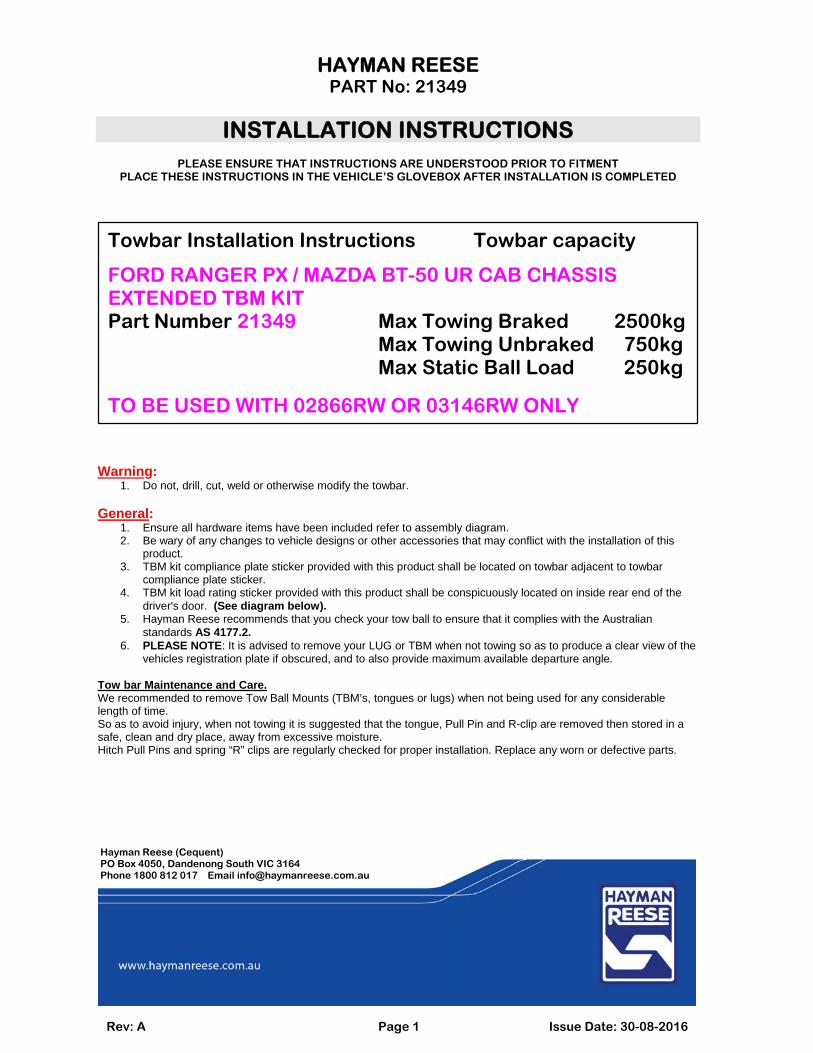
Towbar Installation Instructions Towbar capacity
FORD RANGER PX / MAZDA BT-50 UR CAB CHASSIS EXTENDED TBM KIT Part Number 21349 Max Towing Braked 2500kg Max Towing Unbraked 750kg Max Static Ball Load 250kg
TO BE USED WITH 02866RW OR 03146RW ONLY
HAYMAN REESE PART No: 21349
INSTALLATION INSTRUCTIONS
PLEASE ENSURE THAT INSTRUCTIONS ARE UNDERSTOOD PRIOR TO FITMENT
PLACE THESE INSTRUCTIONS IN THE VEHICLE’S GLOVEBOX AFTER INSTALLATION IS COMPLETED
Rev: A Page 2 Issue Date: 30-08-2016
Hayman Reese (Cequent) PO Box 4050, Dandenong South VIC 3164 Phone 1800 812 017 Email [email protected]
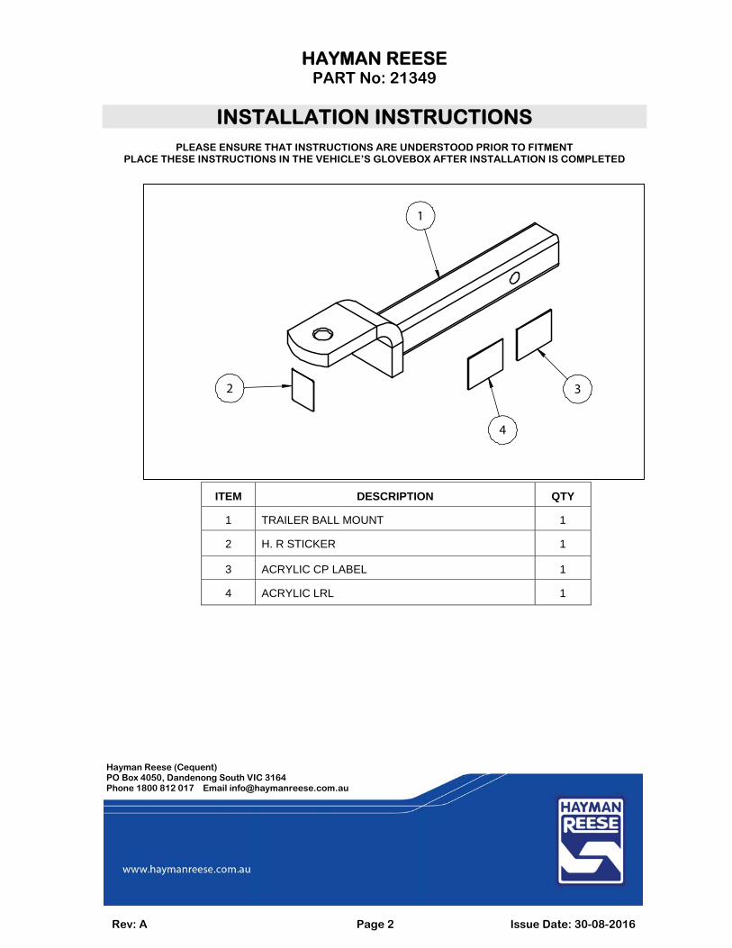
ITEM DESCRIPTION QTY
1 TRAILER BALL MOUNT 1
2 H. R STICKER 1
3 ACRYLIC CP LABEL 1
4 ACRYLIC LRL 1
1
2 3
4
HAYMAN REESE PART No: 21349
INSTALLATION INSTRUCTIONS
PLEASE ENSURE THAT INSTRUCTIONS ARE UNDERSTOOD PRIOR TO FITMENT
PLACE THESE INSTRUCTIONS IN THE VEHICLE’S GLOVEBOX AFTER INSTALLATION IS COMPLETED
Rev: A Page 3 Issue Date: 30-08-2016
Hayman Reese (Cequent) PO Box 4050, Dandenong South VIC 3164 Phone 1800 812 017 Email [email protected]
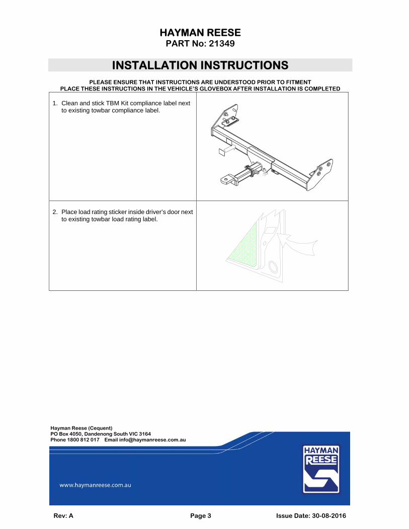
1. Clean and stick TBM Kit compliance label next
to existing towbar compliance label.
2. Place load rating sticker inside driver’s door next
to existing towbar load rating label.
FITTING INSTRUCTIONSSmart Pin (55070BL)
HAYMAN REESEPO BOX 4050, Dandenong South, VIC [email protected] I 1800 812 017haymanreese.com.au
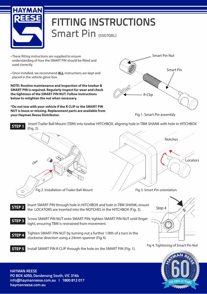
• These �tting instructions are supplied to ensureunderstanding of how the SMART PIN should be �tted andused correctly.
• Once installed, we recommend ALL instructions are kept and placed in the vehicle glove box.
NOTE: Routine maintenance and inspection of the towbar & SMART PIN is required. Regularly inspect for wear and check the tightness of the SMART PIN NUT. Follow instructions below to retighten the nut when necessary.
*Do not tow with your vehicle if the R CLIP or the SMART PINNUT is loose or missing. Replacement parts are available from your Hayman Reese Distributor.
Smart Pin Nut
R-Clip
Smart Pin
Fig 1. Smart Pin assembly
Fig 2. Installation of Trailer Ball Mount
Insert Trailer Ball Mount (TBM) into towbar HITCHBOX, aligning hole in TBM SHANK with hole in HITCHBOX (Fig. 2).
Insert SMART PIN through hole in HITCHBOX and hole in TBM SHANK; ensure the LOCATORS are inserted into the NOTCHES in the HITCHBOX (Fig. 3).
STEP 1
STEP 2
Screw SMART PIN NUT onto SMART PIN; tighten SMART PIN NUT until fingerSTEP 3 tight, ensuring TBM is restrained from movement.
Tighten SMART PIN NUT by turning nut a further 1/8th of a turn in the clockwise direction using a 24mm spanner (Fig 4).
STEP 4
Install SMART PIN R CLIP through the hole on the SMART PIN (Fig. 1). STEP 5
Step 4
Fig 4. Tightening of Smart Pin Nut
Locators
Notches
STEP 3
Fig 3. Smart Pin orientation