Embed Size (px)
Citation preview
31057H402E 0/17
REV.13
INSTALLATION & MAINTENANCE
INSTRUCTIONS
TECO INDUCTION MOTORS UP TO 600KW
31057H402E 1/17
REV.13
INSTALLATION & MAINTENANCE INSTRUCTIONS
This instruction manual is for TECHNICAL USE ONLY, NOT FOR COMMERCIAL PURPOSE. The warranty is limited to coverage expressed in your sales contract. Documentation of storage, transportation, installation and examination, if required, shall be inquired of TECO's service center before start and maintenance.
BEFORE INSTALLATION & USE
1. Ensure nameplate data corresponds with your requirements 2. Ensure the motor is undamaged 3. Remove any shaft clamp (but refit prior to transportation) 4. Slowly rotate the shaft to ensure free movement 5. Ensure the mounting/shaft orientation design and drain hole positions are correct for the
application 6. Eyebolt(s) and any other lifting means must be tight before use
WARNING The following safety precautions must be observed:
1. Electric rotating machinery and electricity can cause serious or fatal injury if the motor is improperly installed, operated or maintained. Responsible personnel must be fully trained to understand the hazards to themselves and others before being involved in installing, operating, maintaining and decommissioning electric motors. European Union Safety information can be obtained from such as:
EN60204-1;EN60034;EN292;EN294;IEE Wiring Regulations
Particular industries and countries have further safety requirements. Refer to their trade & safety bodies.
2. ExCB Ex n Certification Products Special Conditions For Safe Use a. All terminal nuts and screws, whether used or not, shall be correctly tightened. b. Supply connections shall be made with ring type terminal lugs which have insulated
shanks. Clearance distances shall not be reduced when tightening connections. c. On auxiliary terminals the conductor insulation shall extend to within 1 mm of the
terminal throat. d. There shall be no loose conductor strands on any terminal. e. The drain plugs (when fitted) shall be replaced immediately after use and sealed with
an appropriate sealing compound. f. The brass terminal links shall be connected correctly so as not to reduce the clearance
distances.
3. When servicing, all power sources to the motor and to the accessory devices should be de-energized and disconnected and all rotating parts at standstill.
4. Lifting means, such as eyebolts, on the motor are for lifting only the motor itself.
Assemblies which are not part of the motor must be removed prior to using the motor lifting means. When more than one lifting means is provided on the motor, all must be used together, for instance by attaching a supporting chain to each, to share the load. Ensure that lifting means are fully attached to the motor before lifting.
31057H402E 2/17
REV.13
5. Suitable ear protection must be worn near machinery emitting high audible noise to reduce the noise reaching the ear to a safe level. Refer to EN 60034-9 for further information on noise from rotating electrical machines.
6. Safety guards and other protective devices must neither be bypassed nor rendered inoperative.
7. The motor must be earthed. Refer to relevant standards such as EN60204-1, IEE
Wiring Regulations etc. 8. A suitable enclosure must be provided for the motor to prevent access to moving
parts. Extra caution should be observed around a motor that is automatically started or has automatic resetting relays or is remotely started in case such starting means has not been properly disabled and the motor starts unexpectedly.
9. Ensure all shaft keys present on moving parts are fully captive before the motor is
started. 10. Ensure adequate safeguards have been made to protect against the
consequences of a brake failure, particularly on applications involving overhauling loads.
11. TECO UL listed explosion proof motors must only be used in countries where the
UL certification is recognized as being appropriate for the application. They are constructed to comply with the label service procedure manual and repairs to them must be made by TECO or a UL listed service center in order to maintain the UL listing.
12. When using a motor in a variable speed application ensure that it will not be driven
above its safe maximum speed limit. Consult TECO if in doubt. Also ensure the motor is not overloaded:It should be remembered that as speed reduces, fans
driven by the main shaft do not provide as much cooling air and an auxiliary fan may be required.
13. Protect the motor from overload, preferable by monitoring the winding temperature.
TECO can fit thermostats to give indication that the winding is getting too hot and the thermostats can be connected to switchgear that will automatically trip on the signal from the thermostats.
14. Capacitors such as in single-phase motors may remain charged even when
isolated from the mains supply. Discharge capacitors and earth their terminals before handling any connections.
15. All TECO UL listed Explosion Proof motors have temperature limiting devices in
the motor enclosure to help prevent excessive external surface temperature of the motor in accordance with UL standards. Terminals ( P1、P2 ) of thermal protectors
in these motors must be connected to the motor control equipment according to the connection diagram inside the terminal box.
31057H402E 3/17
REV.13
16. If regressing is to be carried out with the motor running, ensure only properly trained
personnel do it and that live and moving parts are fully guarded. 17. Dust Ignition Proof motors Ex tD or the motors with degree of protection greater
than IP55 , the terminal box must be sealed with gaskets to prevent ingress of dust and water. If removed, gaskets must be glued with Loctite 330 or 596 or MXBON TB625.
Location
1. Drip proof motors are intended for use where the atmosphere is relatively clean, dry, well ventilated and non-corrosive. Refer to EN 60034: Part 5 for more detailed information on suitability of a particular enclosure rating.
2. Totally enclosed motors may be installed where dirt, moisture or dust are present and
in outdoor locations. Refer to EN 60034: Part 5 for more detailed information on suitability of a particular enclosure rating.
3. Explosion proof motors have many different categories because hazardous
atmospheres can consist of many different gases, which may or may not be present continuously. Individual countries/users can differ in their safety requirements so the suitability of an explosion proof motor for any particular hazardous location must be assessed against the standards and specifications in force for that location. They must not be used in hazardous locations unless it has been established that they do comply with the safety standards and specifications in force for that location.
4. Before installing, operating or carrying out maintenance services on electric motors
used on hazardous locations, care must be taken on the following: - The standards listed in Annex A, B, C and D applied to each case, must be studied and understood. - All requirements included in the applicable standards must be understood accordingly. - Instruction Marking as listed in Annex A, B, C and D - The Ambient temperature limits are as follows: Ex d / Ex de do not exceed 50C Ex e does not exceed 40C Ex n and ExtD do not exceed 55C - When anti-condensation heaters are fitted they are to be interlocked such that they can only be energized when the motor is de-energized. - The protection class and the IP-class of the cable entry devices when fitted must be at least the same as those of the terminal boxes. - When the motor on delivery, cable entry will be fitted with plastic plug to prevent mist and dust entering. But right after motor be installed, the surplus or unused cable entry must be plugged with ExCB certified plug (e.g. IEC Ex d , Ex e or Ex n) to the terminal box. - The brass terminal link should be connected correctly and power supply bare wire can’t bulge over the bushing nut so as not to reduce the clearance distance.
31057H402E 4/17
REV.13
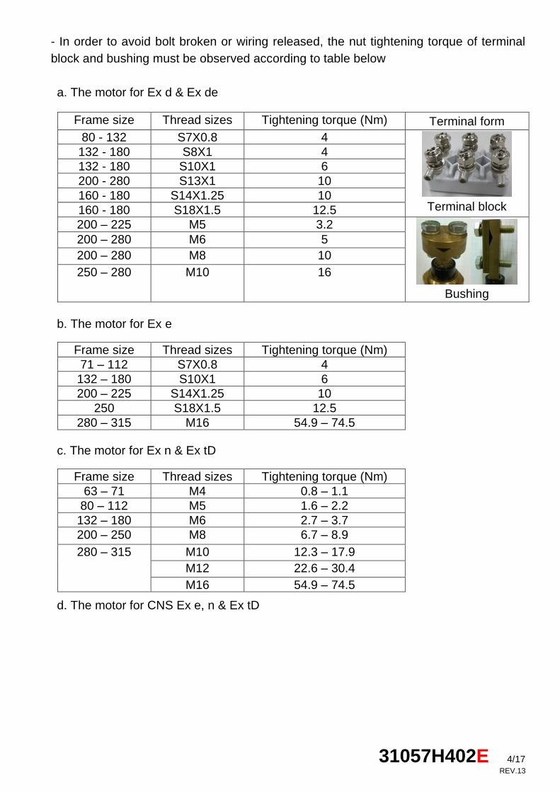
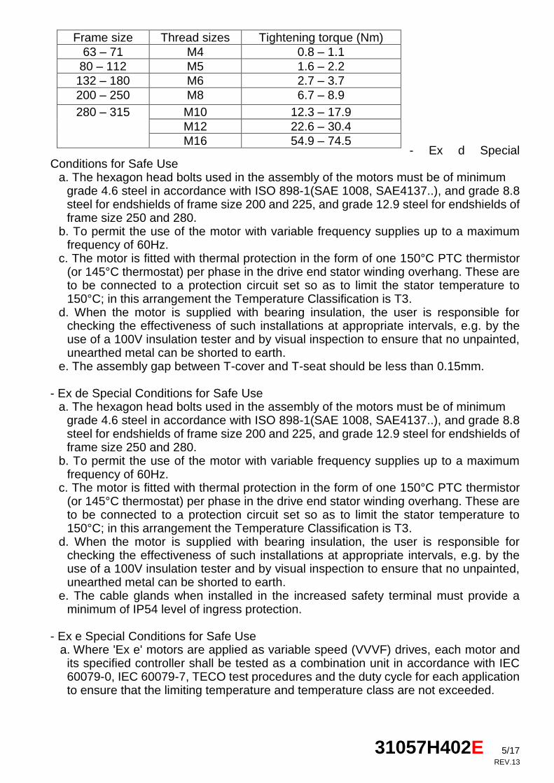
- In order to avoid bolt broken or wiring released, the nut tightening torque of terminal
block and bushing must be observed according to table below
a. The motor for Ex d & Ex de
b. The motor for Ex e
c. The motor for Ex n & Ex tD
d. The motor for CNS Ex e, n & Ex tD
Frame size Thread sizes Tightening torque (Nm) Terminal form
80 - 132 S7X0.8 4
Terminal block
132 - 180 S8X1 4
132 - 180 S10X1 6
200 - 280 S13X1 10
160 - 180 S14X1.25 10
160 - 180 S18X1.5 12.5
200 – 225 M5 3.2
Bushing
200 – 280 M6 5
200 – 280 M8 10
250 – 280 M10 16
Frame size Thread sizes Tightening torque (Nm)
71 – 112 S7X0.8 4
132 – 180 S10X1 6
200 – 225 S14X1.25 10
250 S18X1.5 12.5
280 – 315 M16 54.9 – 74.5
Frame size Thread sizes Tightening torque (Nm)
63 – 71 M4 0.8 – 1.1
80 – 112 M5 1.6 – 2.2
132 – 180 M6 2.7 – 3.7
200 – 250 M8 6.7 – 8.9
280 – 315 M10 12.3 – 17.9
M12 22.6 – 30.4
M16 54.9 – 74.5
31057H402E 5/17
REV.13
- Ex d Special
Conditions for Safe Use a. The hexagon head bolts used in the assembly of the motors must be of minimum
grade 4.6 steel in accordance with ISO 898-1(SAE 1008, SAE4137..), and grade 8.8 steel for endshields of frame size 200 and 225, and grade 12.9 steel for endshields of frame size 250 and 280.
b. To permit the use of the motor with variable frequency supplies up to a maximum frequency of 60Hz.
c. The motor is fitted with thermal protection in the form of one 150°C PTC thermistor (or 145°C thermostat) per phase in the drive end stator winding overhang. These are to be connected to a protection circuit set so as to limit the stator temperature to 150°C; in this arrangement the Temperature Classification is T3.
d. When the motor is supplied with bearing insulation, the user is responsible for checking the effectiveness of such installations at appropriate intervals, e.g. by the use of a 100V insulation tester and by visual inspection to ensure that no unpainted, unearthed metal can be shorted to earth.
e. The assembly gap between T-cover and T-seat should be less than 0.15mm.
- Ex de Special Conditions for Safe Use a. The hexagon head bolts used in the assembly of the motors must be of minimum
grade 4.6 steel in accordance with ISO 898-1(SAE 1008, SAE4137..), and grade 8.8 steel for endshields of frame size 200 and 225, and grade 12.9 steel for endshields of frame size 250 and 280.
b. To permit the use of the motor with variable frequency supplies up to a maximum frequency of 60Hz.
c. The motor is fitted with thermal protection in the form of one 150°C PTC thermistor (or 145°C thermostat) per phase in the drive end stator winding overhang. These are to be connected to a protection circuit set so as to limit the stator temperature to 150°C; in this arrangement the Temperature Classification is T3.
d. When the motor is supplied with bearing insulation, the user is responsible for checking the effectiveness of such installations at appropriate intervals, e.g. by the use of a 100V insulation tester and by visual inspection to ensure that no unpainted, unearthed metal can be shorted to earth.
e. The cable glands when installed in the increased safety terminal must provide a minimum of IP54 level of ingress protection.
- Ex e Special Conditions for Safe Use
a. Where 'Ex e' motors are applied as variable speed (VVVF) drives, each motor and its specified controller shall be tested as a combination unit in accordance with IEC 60079-0, IEC 60079-7, TECO test procedures and the duty cycle for each application to ensure that the limiting temperature and temperature class are not exceeded.
Frame size Thread sizes Tightening torque (Nm)
63 – 71 M4 0.8 – 1.1
80 – 112 M5 1.6 – 2.2
132 – 180 M6 2.7 – 3.7
200 – 250 M8 6.7 – 8.9
280 – 315 M10 12.3 – 17.9
M12 22.6 – 30.4
M16 54.9 – 74.5
31057H402E 6/17
REV.13
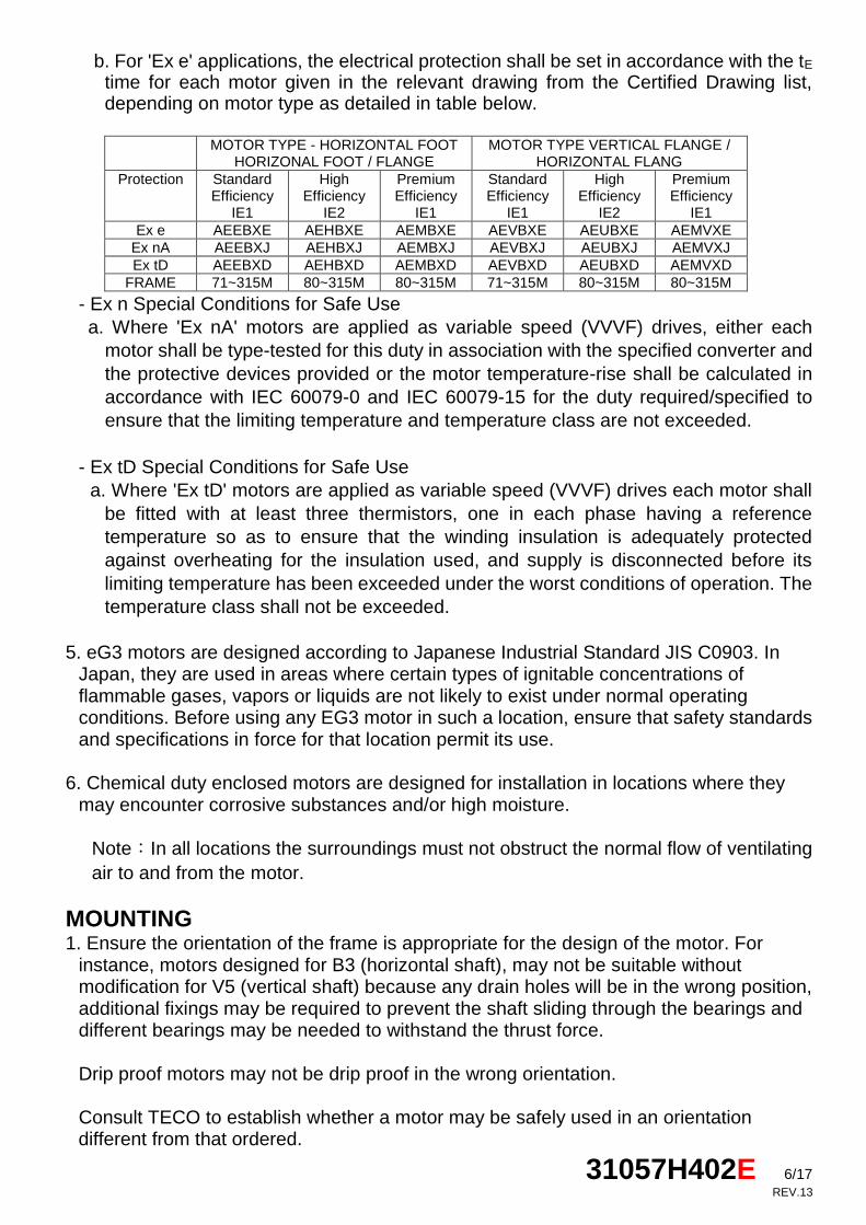
b. For 'Ex e' applications, the electrical protection shall be set in accordance with the tE time for each motor given in the relevant drawing from the Certified Drawing list, depending on motor type as detailed in table below.
MOTOR TYPE - HORIZONTAL FOOT
HORIZONAL FOOT / FLANGE MOTOR TYPE VERTICAL FLANGE /
HORIZONTAL FLANG
Protection Standard Efficiency
IE1
High Efficiency
IE2
Premium Efficiency
IE1
Standard Efficiency
IE1
High Efficiency
IE2
Premium Efficiency
IE1
Ex e AEEBXE AEHBXE AEMBXE AEVBXE AEUBXE AEMVXE
Ex nA AEEBXJ AEHBXJ AEMBXJ AEVBXJ AEUBXJ AEMVXJ
Ex tD AEEBXD AEHBXD AEMBXD AEVBXD AEUBXD AEMVXD
FRAME 71~315M 80~315M 80~315M 71~315M 80~315M 80~315M
- Ex n Special Conditions for Safe Use
a. Where 'Ex nA' motors are applied as variable speed (VVVF) drives, either each
motor shall be type-tested for this duty in association with the specified converter and
the protective devices provided or the motor temperature-rise shall be calculated in
accordance with IEC 60079-0 and IEC 60079-15 for the duty required/specified to
ensure that the limiting temperature and temperature class are not exceeded.
- Ex tD Special Conditions for Safe Use
a. Where 'Ex tD' motors are applied as variable speed (VVVF) drives each motor shall
be fitted with at least three thermistors, one in each phase having a reference
temperature so as to ensure that the winding insulation is adequately protected
against overheating for the insulation used, and supply is disconnected before its
limiting temperature has been exceeded under the worst conditions of operation. The
temperature class shall not be exceeded.
5. eG3 motors are designed according to Japanese Industrial Standard JIS C0903. In Japan, they are used in areas where certain types of ignitable concentrations of flammable gases, vapors or liquids are not likely to exist under normal operating conditions. Before using any EG3 motor in such a location, ensure that safety standards and specifications in force for that location permit its use.
6. Chemical duty enclosed motors are designed for installation in locations where they
may encounter corrosive substances and/or high moisture.
Note:In all locations the surroundings must not obstruct the normal flow of ventilating
air to and from the motor.
MOUNTING 1. Ensure the orientation of the frame is appropriate for the design of the motor. For
instance, motors designed for B3 (horizontal shaft), may not be suitable without modification for V5 (vertical shaft) because any drain holes will be in the wrong position, additional fixings may be required to prevent the shaft sliding through the bearings and different bearings may be needed to withstand the thrust force.
Drip proof motors may not be drip proof in the wrong orientation. Consult TECO to establish whether a motor may be safely used in an orientation different from that ordered.
31057H402E 7/17
REV.13
2. Where the motor is to be subject to a high degree of vibration (such as on a vibrating
screen), high humidity (typically above 95%), abnormal ambient temperature (typically outside the range -20 to +45℃), or high altitude (typically above 1000meter) ensure that
the motor specification is appropriate. 3. When mounting the motor, ensure this is done securely using steel nuts and bolts
through each of the fixing holes provided, fully tightened. Where the location is likely to cause rusting, such as in the presence of sea water, stainless steel fixing bolts may be an advantage. Where there is significant vibration, ensure there are shakeproof washers under the nuts.
4. Where the drain holes are to be left open, ensure they are guarded from access when
the motor windings are connected to a power supply.
5. With a directly-coupled load ensure the motor and load shafts are accurately aligned
and use a flexible coupling between them. Mounting bolts must be carefully tightened to
avoid alignment changes and the alignment rechecked to ensure it is correct when the
bolts are fully tight.
6. With a side-coupled load, such as a belt or gear drive, ensure the side force on the
shaft will not damage the motor. Consult TECO if in doubt.
7. If motors mounted with the shaft upwards and water or liquid are expected to go down
along the shaft part, the user must consider mounting some capable means to
preventing it.
POWER SUPPLY AND CONNECTIONS 1. Wiring of the motor and its controller, overload protection and earthing should be in
accordance with the current edition of the IEE wiring regulations, EN60204 and all local
safety requirements.
2. Refer to the nameplate voltage, frequency and current to ensure the motor is correct for
the material of wire and the power supply to which it is to be connected. Unless specified
otherwise the motor may be assumed to be suitable for the nameplate voltage +/-5%
and nameplate frequency +/-1%.
3. Connection diagrams for the motor are generally supplied with it, either on the
nameplate, fixed to the motor or placed in the terminal box.
4. All TECO UL listed Explosion Proof motors have temperature limiting devices in the
motor enclosure to help prevent excessive external surface temperature of the motor in
accordance with UL standards. Terminals (P1, P2) of thermal protectors in these motors
must be connected to the motor control equipment according to the connection diagram
inside the terminal box.
Start up 1. Initially, run the motor unloaded and establish that the rotation direction is as required.
31057H402E 8/17
REV.13
If not, switch off and when rotation has stopped:
- if the motor is a three phase motor – interchange any two phases.
- if the motor is a single phase motor – interchange the connections to the auxiliary
winding circuit, leaving the connections to the main winding unchanged.
2. Then start the motor fully loaded. If it does not start quickly and run smoothly, switch off
immediately and when rotation has stopped, isolate from the power supply and examine
the assembly for mechanical faults or poor connections.
3. If there is excessive vibration it could be caused by poorly-aligned couplings, loose
mounting bolts, lack of rigidity in the supports, transmitted vibration from adjacent
machinery etc. Excessive vibration can lead to motor damage, for instance to the
bearings making them noisy, and hence vibration should be minimized.
4. Ensure the current drawn is commensurate with that shown on the nameplate and that
the currents in each phase are similar.
5. If a single phase motor does not start, this may be due to the internal starting switch not
closing when the rotor is stationary or a faulty starting capacitor.
Long term storage and humid environments 1. If the motor has been stored for an extensive period or subjected to adverse moisture
conditions, ensure the insulation resistance is greater than 1M Ohm before switching on.
Also, regrease the bearings and if they are rusty, replace them.
When the insulation resistance is not greater than 1M Ohm, dry out the motor as
described below. If after drying out the insulation resistance is still not greater than 1M
Ohm, the motor will need repairing.
2. Place
(a) High and dry, well-ventilated without direct sun, dust or corrosive gas.
(b) Not located near to a boiler or freezer.
(c) Entirely free from vibration and easy for movements.
(d) Motors should be put on pallets to prevent moisture.
Drying out This may be carried out either:
1. By baking in an oven at up to 90℃. Ensure the interior and exterior of the oven are well
ventilated.
2. By locking the rotor so it cannot move and connecting a low voltage to the motor
windings. gradually increase the voltage from zero until the current is about one third the
rating plate value. Trim the voltage as necessary so that the winding temperature
remains below 90℃.
31057H402E 9/17
REV.13
Drying out is complete when the insulation resistance stops changing. Maintenance
Inspection
Inspect the motor at regular intervals. Ensure it is kept clean with clear ventilation
openings, there is no excessive vibration and noise emitted from the motor are normal.
Ensure fixings and fasteners have not loosened nor so corroded that either their
strength has been reduced significantly or earthing has been impaired, Ensure also that
electrical connections are tight and uncorroded and that earthing is intact.
Inspect shaft seals and terminal box gaskets to ensure they are in position and not
significantly worn. Contact TECO if the seal/gasket types on the motor are unknown.
Examine the paint finish and repaint if necessary to avoid excessive corrosion. Ensure
that shaft couplings are fixed firmly and that shaft alignment is correct. Ensure also that
there is no build up of liquid inside the motor that would adversely affect its performance
and drain if there is.
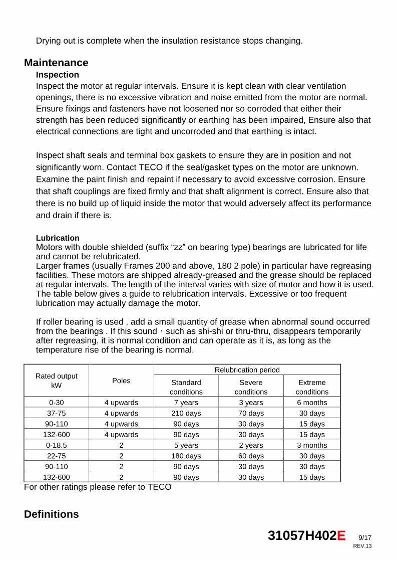
Lubrication Motors with double shielded (suffix “zz” on bearing type) bearings are lubricated for life and cannot be relubricated. Larger frames (usually Frames 200 and above, 180 2 pole) in particular have regreasing facilities. These motors are shipped already-greased and the grease should be replaced at regular intervals. The length of the interval varies with size of motor and how it is used. The table below gives a guide to relubrication intervals. Excessive or too frequent lubrication may actually damage the motor. If roller bearing is used , add a small quantity of grease when abnormal sound occurred from the bearings . If this sound,such as shi-shi or thru-thru, disappears temporarily after regreasing, it is normal condition and can operate as it is, as long as the temperature rise of the bearing is normal.
Rated output
kW Poles
Relubrication period
Standard
conditions
Severe
conditions
Extreme
conditions
0-30 4 upwards 7 years 3 years 6 months
37-75 4 upwards 210 days 70 days 30 days
90-110 4 upwards 90 days 30 days 15 days
132-600 4 upwards 90 days 30 days 15 days
0-18.5 2 5 years 2 years 3 months
22-75 2 180 days 60 days 30 days
90-110 2 90 days 30 days 30 days
132-600 2 90 days 30 days 15 days
For other ratings please refer to TECO
Definitions
31057H402E 10/17
REV.13
Standard conditions: 8 hour operation per day with rated or light loading in a clean low-vibration environment Severe conditions: 24 hour operation per day with rated/light loading or in a dirty/dusty environment or where the motor is subject to vibration/light shock loading Extreme conditions: Where there is heavy shock loading or high vibration or a very dirty/dusty environment
Regreasing operation If regreasing is to be carried out with the motor running, ensure it is done only by
properly-trained personnel and that live and that live and moving parts are fully guarded.
Ensure the grease exit is open and the grease nipple is clean. Attach a low pressure grease gun to the nipple and pump in grease until clean grease emerges at the grease exit. Remove the grease gun. Fully guard live and moving parts and then run the motor for 10-30 minutes ensuring that any surplus grease is properly disposed of, and then refit any grease exit plug.
Grease Type Ensure only the correct type of grease is used. Greases incompatible with that in the bearings can greatly reduce the bearing life. Consult TECO if you are not sure of the type supplied in your TECO motor. TECO standard regreasable motors use MULTEMP SRL or ALVANIA RL3 grease. Information on the lubrication nameplate shall be followed as first priority.
Spares Use only genuine TECO spares or alternatives recommended by TECO When ordering, please give full nameplate details and in particular: Frame Number Type Poles kW Serial Number Quantity required
Disposal of unserviceable and end-of life motors and parts. The motors consist by weight, primarily of cast iron, steel, copper and aluminium alloy. They also have some plastic material for instance, for insulation, sealing and termination of conductors and varnish for impregnation of the winding. The fan and internal baffles may be of plastic. Typically the metals are recyclable by burning off in a furnace the non-metallic material and either breaking or melting the metals into their constituents. Ensure the gases given off during the burning do not pollute. The furnace may need a license or evidence giving them exemption (for instance if they are small) to carry this out. The above suggestions for recycling should be taken as guidance only. Dispose of according to the regulations in force locally.
31057H402E 11/17
REV.13
TECO ELECTRIC & MACHINERY CO., LTD
10F, No.3-1, Yuan Cyu St. Nan-Kang Taipei 115, Taiwan
TEL:+886-2-6615-9111
FAX:+886-2-6615-2253
+886-2-6615-1220
Web:http://www.teco.com.tw
http://www.tecomotor.com.tw
31057H402E 12/17
REV.13
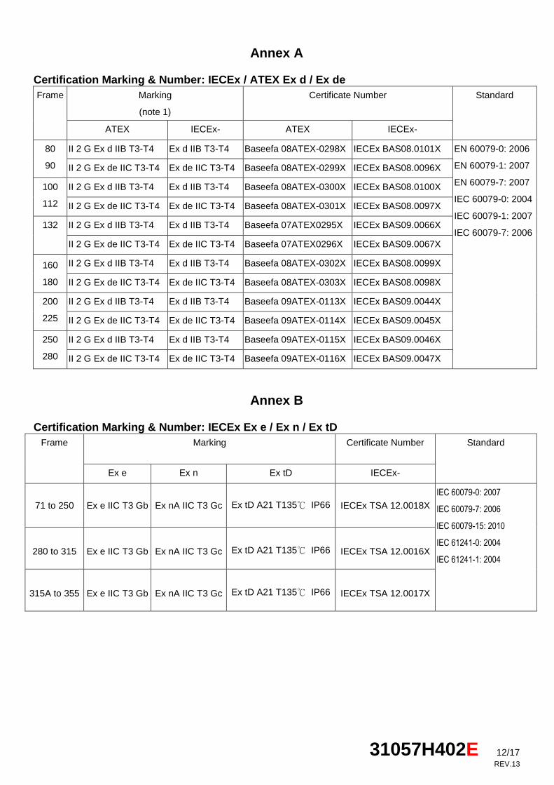
Annex A Certification Marking & Number: IECEx / ATEX Ex d / Ex de
Frame Marking
(note 1)
Certificate Number Standard
ATEX IECEx- ATEX IECEx-
80
90
II 2 G Ex d IIB T3-T4 Ex d IIB T3-T4 Baseefa 08ATEX-0298X IECEx BAS08.0101X EN 60079-0: 2006
EN 60079-1: 2007
EN 60079-7: 2007
IEC 60079-0: 2004
IEC 60079-1: 2007
IEC 60079-7: 2006
II 2 G Ex de IIC T3-T4 Ex de IIC T3-T4 Baseefa 08ATEX-0299X IECEx BAS08.0096X
100
112
II 2 G Ex d IIB T3-T4 Ex d IIB T3-T4 Baseefa 08ATEX-0300X IECEx BAS08.0100X
II 2 G Ex de IIC T3-T4 Ex de IIC T3-T4 Baseefa 08ATEX-0301X IECEx BAS08.0097X
132 II 2 G Ex d IIB T3-T4 Ex d IIB T3-T4 Baseefa 07ATEX0295X IECEx BAS09.0066X
II 2 G Ex de IIC T3-T4 Ex de IIC T3-T4 Baseefa 07ATEX0296X IECEx BAS09.0067X
160
180
II 2 G Ex d IIB T3-T4 Ex d IIB T3-T4 Baseefa 08ATEX-0302X IECEx BAS08.0099X
II 2 G Ex de IIC T3-T4 Ex de IIC T3-T4 Baseefa 08ATEX-0303X IECEx BAS08.0098X
200
225
II 2 G Ex d IIB T3-T4 Ex d IIB T3-T4 Baseefa 09ATEX-0113X IECEx BAS09.0044X
II 2 G Ex de IIC T3-T4 Ex de IIC T3-T4 Baseefa 09ATEX-0114X IECEx BAS09.0045X
250
280
II 2 G Ex d IIB T3-T4 Ex d IIB T3-T4 Baseefa 09ATEX-0115X IECEx BAS09.0046X
II 2 G Ex de IIC T3-T4 Ex de IIC T3-T4 Baseefa 09ATEX-0116X IECEx BAS09.0047X
Annex B Certification Marking & Number: IECEx Ex e / Ex n / Ex tD
Frame Marking Certificate Number Standard
Ex e Ex n Ex tD IECEx-
71 to 250 Ex e IIC T3 Gb Ex nA IIC T3 Gc Ex tD A21 T135℃ IP66 IECEx TSA 12.0018X
IEC 60079-0: 2007
IEC 60079-7: 2006
IEC 60079-15: 2010
IEC 61241-0: 2004
IEC 61241-1: 2004 280 to 315 Ex e IIC T3 Gb Ex nA IIC T3 Gc Ex tD A21 T135℃ IP66 IECEx TSA 12.0016X
315A to 355 Ex e IIC T3 Gb Ex nA IIC T3 Gc Ex tD A21 T135℃ IP66 IECEx TSA 12.0017X
31057H402E 13/17
REV.13
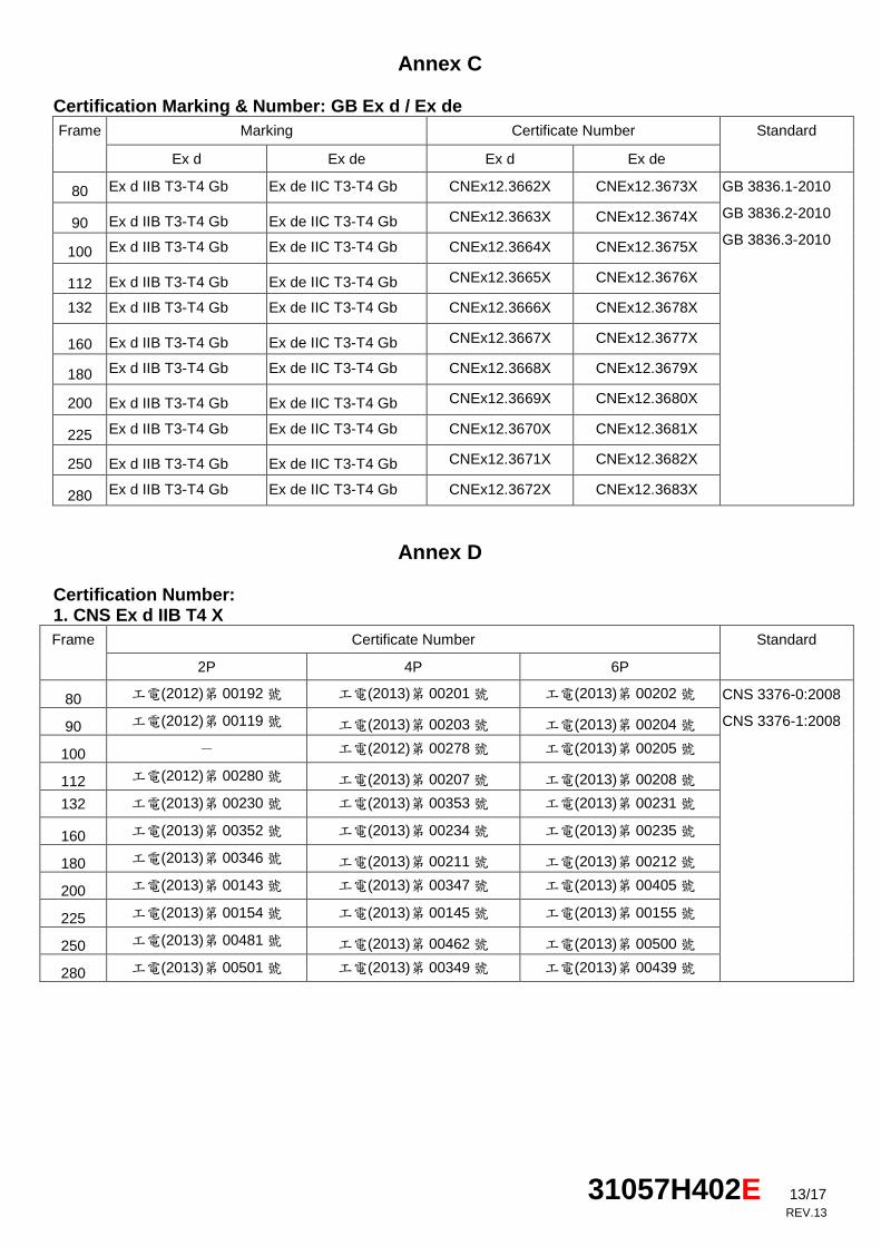
Annex C Certification Marking & Number: GB Ex d / Ex de
Frame Marking Certificate Number Standard
Ex d Ex de Ex d Ex de
80 Ex d IIB T3-T4 Gb Ex de IIC T3-T4 Gb CNEx12.3662X CNEx12.3673X GB 3836.1-2010
GB 3836.2-2010
GB 3836.3-2010 90 Ex d IIB T3-T4 Gb Ex de IIC T3-T4 Gb CNEx12.3663X CNEx12.3674X
100 Ex d IIB T3-T4 Gb Ex de IIC T3-T4 Gb CNEx12.3664X CNEx12.3675X
112 Ex d IIB T3-T4 Gb Ex de IIC T3-T4 Gb CNEx12.3665X CNEx12.3676X
132 Ex d IIB T3-T4 Gb Ex de IIC T3-T4 Gb CNEx12.3666X CNEx12.3678X
160 Ex d IIB T3-T4 Gb Ex de IIC T3-T4 Gb CNEx12.3667X CNEx12.3677X
180 Ex d IIB T3-T4 Gb Ex de IIC T3-T4 Gb CNEx12.3668X CNEx12.3679X
200 Ex d IIB T3-T4 Gb Ex de IIC T3-T4 Gb CNEx12.3669X CNEx12.3680X
225 Ex d IIB T3-T4 Gb Ex de IIC T3-T4 Gb CNEx12.3670X CNEx12.3681X
250 Ex d IIB T3-T4 Gb Ex de IIC T3-T4 Gb CNEx12.3671X CNEx12.3682X
280 Ex d IIB T3-T4 Gb Ex de IIC T3-T4 Gb CNEx12.3672X CNEx12.3683X
Annex D Certification Number: 1. CNS Ex d IIB T4 X
Frame Certificate Number Standard
2P 4P 6P
80 工電(2012)第 00192號 工電(2013)第 00201號 工電(2013)第 00202號 CNS 3376-0:2008
CNS 3376-1:2008 90 工電(2012)第 00119號 工電(2013)第 00203號 工電(2013)第 00204號
100 - 工電(2012)第 00278號 工電(2013)第 00205號
112 工電(2012)第 00280號 工電(2013)第 00207號 工電(2013)第 00208號
132 工電(2013)第 00230號 工電(2013)第 00353號 工電(2013)第 00231號
160 工電(2013)第 00352號 工電(2013)第 00234號 工電(2013)第 00235號
180 工電(2013)第 00346號 工電(2013)第 00211號 工電(2013)第 00212號
200 工電(2013)第 00143號 工電(2013)第 00347號 工電(2013)第 00405號
225 工電(2013)第 00154號 工電(2013)第 00145號 工電(2013)第 00155號
250 工電(2013)第 00481號 工電(2013)第 00462號 工電(2013)第 00500號
280 工電(2013)第 00501號 工電(2013)第 00349號 工電(2013)第 00439號
31057H402E 14/17
REV.13
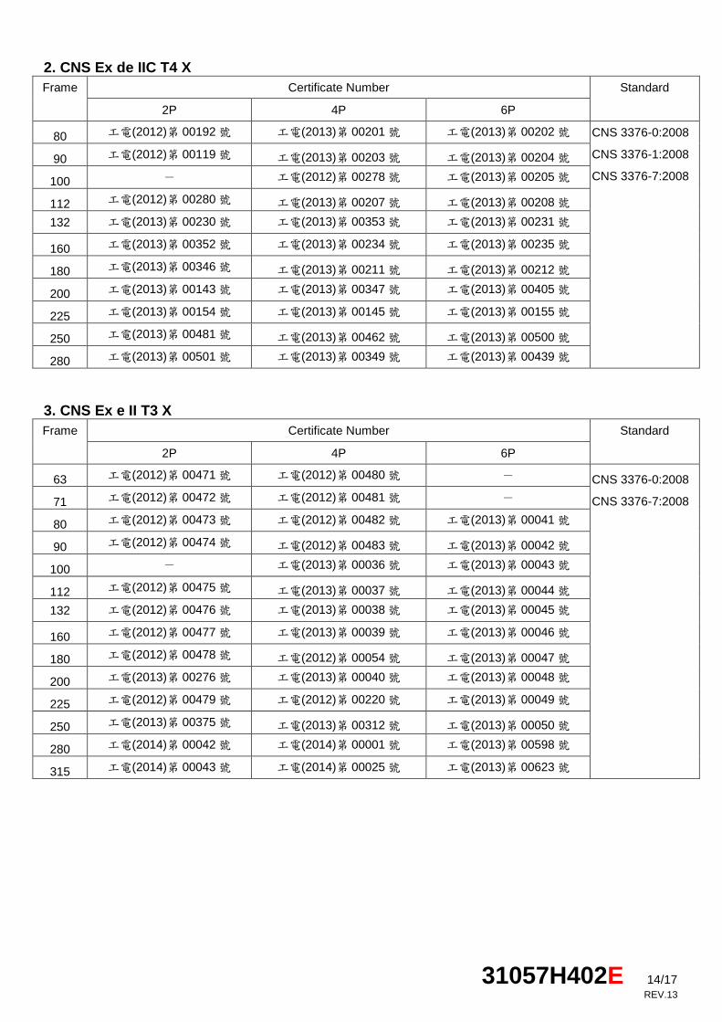
2. CNS Ex de IIC T4 X
Frame Certificate Number Standard
2P 4P 6P
80 工電(2012)第 00192號 工電(2013)第 00201號 工電(2013)第 00202號 CNS 3376-0:2008
CNS 3376-1:2008
CNS 3376-7:2008
90 工電(2012)第 00119號 工電(2013)第 00203號 工電(2013)第 00204號
100 - 工電(2012)第 00278號 工電(2013)第 00205號
112 工電(2012)第 00280號 工電(2013)第 00207號 工電(2013)第 00208號
132 工電(2013)第 00230號 工電(2013)第 00353號 工電(2013)第 00231號
160 工電(2013)第 00352號 工電(2013)第 00234號 工電(2013)第 00235號
180 工電(2013)第 00346號 工電(2013)第 00211號 工電(2013)第 00212號
200 工電(2013)第 00143號 工電(2013)第 00347號 工電(2013)第 00405號
225 工電(2013)第 00154號 工電(2013)第 00145號 工電(2013)第 00155號
250 工電(2013)第 00481號 工電(2013)第 00462號 工電(2013)第 00500號
280 工電(2013)第 00501號 工電(2013)第 00349號 工電(2013)第 00439號
3. CNS Ex e II T3 X
Frame Certificate Number Standard
2P 4P 6P
63 工電(2012)第 00471號 工電(2012)第 00480號 - CNS 3376-0:2008
CNS 3376-7:2008 71 工電(2012)第 00472號 工電(2012)第 00481號 -
80 工電(2012)第 00473號 工電(2012)第 00482號 工電(2013)第 00041號
90 工電(2012)第 00474號 工電(2012)第 00483號 工電(2013)第 00042號
100 - 工電(2013)第 00036號 工電(2013)第 00043號
112 工電(2012)第 00475號 工電(2013)第 00037號 工電(2013)第 00044號
132 工電(2012)第 00476號 工電(2013)第 00038號 工電(2013)第 00045號
160 工電(2012)第 00477號 工電(2013)第 00039號 工電(2013)第 00046號
180 工電(2012)第 00478號 工電(2012)第 00054號 工電(2013)第 00047號
200 工電(2013)第 00276號 工電(2013)第 00040號 工電(2013)第 00048號
225 工電(2012)第 00479號 工電(2012)第 00220號 工電(2013)第 00049號
250 工電(2013)第 00375號 工電(2013)第 00312號 工電(2013)第 00050號
280 工電(2014)第 00042號 工電(2014)第 00001號 工電(2013)第 00598號
315 工電(2014)第 00043號 工電(2014)第 00025號 工電(2013)第 00623號
31057H402E 15/17
REV.13
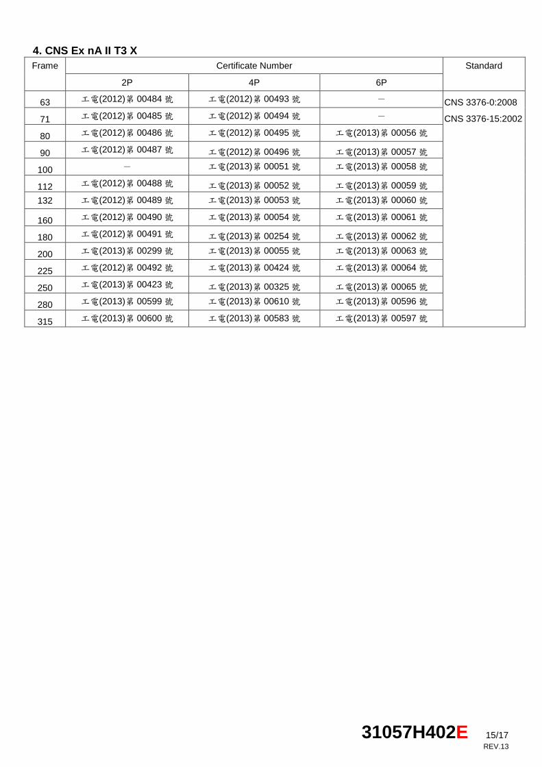
4. CNS Ex nA II T3 X
Frame Certificate Number Standard
2P 4P 6P
63 工電(2012)第 00484號 工電(2012)第 00493號 - CNS 3376-0:2008
CNS 3376-15:2002 71 工電(2012)第 00485號 工電(2012)第 00494號 -
80 工電(2012)第 00486號 工電(2012)第 00495號 工電(2013)第 00056號
90 工電(2012)第 00487號 工電(2012)第 00496號 工電(2013)第 00057號
100 - 工電(2013)第 00051號 工電(2013)第 00058號
112 工電(2012)第 00488號 工電(2013)第 00052號 工電(2013)第 00059號
132 工電(2012)第 00489號 工電(2013)第 00053號 工電(2013)第 00060號
160 工電(2012)第 00490號 工電(2013)第 00054號 工電(2013)第 00061號
180 工電(2012)第 00491號 工電(2013)第 00254號 工電(2013)第 00062號
200 工電(2013)第 00299號 工電(2013)第 00055號 工電(2013)第 00063號
225 工電(2012)第 00492號 工電(2013)第 00424號 工電(2013)第 00064號
250 工電(2013)第 00423號 工電(2013)第 00325號 工電(2013)第 00065號
280 工電(2013)第 00599號 工電(2013)第 00610號 工電(2013)第 00596號
315 工電(2013)第 00600號 工電(2013)第 00583號 工電(2013)第 00597號