Embed Size (px)
Citation preview
Installation & Maintenance Manual
BT Versatility Installation and maintenance Manual
1
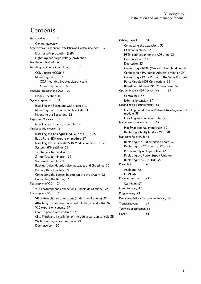
Contents Introduction 2
General overview 2 Safety Precautions during installation and system upgrades 3
Electrostatic precaution (ESP) 3
Lightning and surge voltage protection 3 Installation checklist 6
Installing the Central Control Unit 7
CCU Location(CCU) 7
Mounting the CCU 7
CCU Mounting bracket clearances 8 Mounting the CCU 9
Modules located in the CCU 10
Module location 10 System Expansion 11
Installing the Backplane wall bracket 11
Mounting the CCU with two brackets 11
Mounting the Backplane 12 Expansion Modules 13
Installing an Expansion module 14 Analogue line module 15
Installing the Analogue Module in the CCU 15
Basic Rate ISDN expansion module 17
Installing the Basic Rate ISDN Module in the CCU 17
System ISDN settings 19
T0 interface termination 19
S0 interface termination 19
Voicemail module 20
Back up Voice Module voice messages and Greetings 20
Primary Rate Interface 21
Connecting the battery backup unit to the system 22
Connecting the Battery 23 Featurephone V16 24
V16 Featurephone connections (underside of phone) 24 Featurephone V8 25
V8 Featurephone connections (underside of phone) 25
Attaching the Featurephone desk plinth (V8 and V16) 26
V16 expansion console 27
Feature phone with console 27
Clip, Plinth and installation of the V16 expansion console 28
Wall-mounting a Featurephone 29
Door Intercom 30
Cabling the unit 31
Connecting the extensions 31
CCU connections 33
PSTN connection for the ADSL line 33
Door Intercom 33
Doorstrike 33
Connecting a MOH (Music On Hold Module) 34
Connecting a PA (public Address) amplifier 34
Connecting a PC or Printer to the Serial Port 34
Ports Module MDF Connections 35
Broadband Module MDF Connections 36 Options Module MDF Connections 37
Central Bell 37
External Extension 37 Expanding an Existing system 38
Installing an additional Network (Analogue or ISDN) module 38
Installing additional modules 38 Maintenance procedures 39
Hot Swapping faulty modules 39
Replacing a faulty Module MDF 40 Replacing Faulty PCBs 41
Replacing the 008 extension board 41
Replacing the CCU Control PCB 42
Power supply unit spare fuse 43
Replacing the Power Supply Unit 44
Replacing the CCU MDF 45 Power fail 46
Analogue 46
ISDN 46 Power up and test 47
Switch on 47 Commissioning 47
Programming 48
Recommendations for customer training 56
Troubleshooting 57
Technical specification 58
INDEX 61
BT Versatility Installation and maintenance Manual
2
Introduction This document describes the practices to be adopted by field engineers during installation and maintenance of the BT Versatility. A more detailed description of the product, along with customer programmable facilities and features, may be found in the BT Versatility Owner's Manual, Broadband Guide and Internet Guide which should be read in conjunction with this document.
General overview • The BT Versatility is a new converged PBX and Data product, which can be connected to Analogue ,
ISDN and LAN networks.
• The BT Versatility is a hybrid PABX/key-system, which may be equipped with Featurephones (V8 or
V16) or standard two wire DTMF telephones. Extensions can also be equipped with Fax or Answering
machines.
• The BT Versatility is modular in construction and can be upgraded by adding various system
expansion modules (Ports Modules, Options Module, Music on Hold module and Broadband Module).
• The BT Versatility allows Voice connectivity to ISDN and Analogue MF exchange lines.
• The BT Versatility may be configured with up to four internal S-Bus interfaces for connection to
approved ISDN apparatus.
• The BT Versatility is a versatile, easy-to-use system, which is simple to install and maintain.
• The BT Versatility Broadband Module. This provides Data connectivity to the Internet via ISDN or
ADSL lines. It provides an internal LAN. It also provides VoIP trunks which allows voice calls from
extensions to be carried over a Broadband Voice Service Provider (such as BT Broadband Voice) or a
managed IP network.
• The BT Versatility Internet Module. This provides Data connectivity to the Internet via ISDN or
ADSL lines. It also provides an internal LAN.
Note: This module is no longer supplied.
The CE Marking on this equipment indicates compliance with the following: This device conforms to Directive 1999/5/EC on Radio Equipment and Telecommunications Terminal Equipment as adopted by the European Parliament And Of The Council.
BT Versatility Installation and Maintenance Manual
3
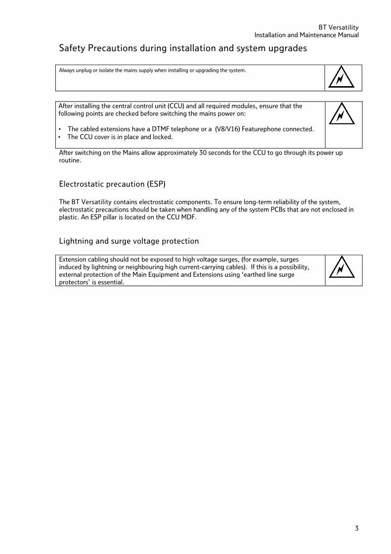
Safety Precautions during installation and system upgrades Always unplug or isolate the mains supply when installing or upgrading the system.
After installing the central control unit (CCU) and all required modules, ensure that the following points are checked before switching the mains power on: • The cabled extensions have a DTMF telephone or a (V8/V16) Featurephone connected. • The CCU cover is in place and locked.
After switching on the Mains allow approximately 30 seconds for the CCU to go through its power up routine.
Electrostatic precaution (ESP) The BT Versatility contains electrostatic components. To ensure long-term reliability of the system, electrostatic precautions should be taken when handling any of the system PCBs that are not enclosed in plastic. An ESP pillar is located on the CCU MDF.
Lightning and surge voltage protection Extension cabling should not be exposed to high voltage surges, (for example, surges induced by lightning or neighbouring high current-carrying cables). If this is a possibility, external protection of the Main Equipment and Extensions using ‘earthed line surge protectors’ is essential.
BT Versatility Installation and maintenance Manual
4
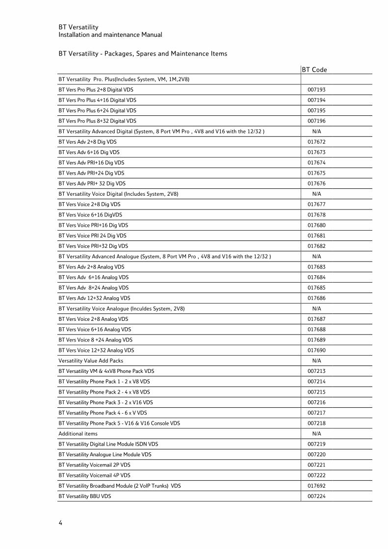
BT Versatility - Packages, Spares and Maintenance Items
BT Code
BT Versatility Pro. Plus(Includes System, VM, 1M,2V8)
BT Vers Pro Plus 2+8 Digital VDS 007193
BT Vers Pro Plus 4+16 Digital VDS 007194
BT Vers Pro Plus 6+24 Digital VDS 007195
BT Vers Pro Plus 8+32 Digital VDS 007196
BT Versatility Advanced Digital (System, 8 Port VM Pro , 4V8 and V16 with the 12/32 ) N/A
BT Vers Adv 2+8 Dig VDS 017672
BT Vers Adv 6+16 Dig VDS 017673
BT Vers Adv PRI+16 Dig VDS 017674
BT Vers Adv PRI+24 Dig VDS 017675
BT Vers Adv PRI+ 32 Dig VDS 017676
BT Versatility Voice Digital (Includes System, 2V8) N/A
BT Vers Voice 2+8 Dig VDS 017677
BT Vers Voice 6+16 DigVDS 017678
BT Vers Voice PRI+16 Dig VDS 017680
BT Vers Voice PRI 24 Dig VDS 017681
BT Vers Voice PRI+32 Dig VDS 017682
BT Versatility Advanced Analogue (System, 8 Port VM Pro , 4V8 and V16 with the 12/32 ) N/A
BT Vers Adv 2+8 Analog VDS 017683
BT Vers Adv 6+16 Analog VDS 017684
BT Vers Adv 8+24 Analog VDS 017685
BT Vers Adv 12+32 Analog VDS 017686
BT Versatility Voice Analogue (Inculdes System, 2V8) N/A
BT Vers Voice 2+8 Analog VDS 017687
BT Vers Voice 6+16 Analog VDS 017688
BT Vers Voice 8 +24 Analog VDS 017689
BT Vers Voice 12+32 Analog VDS 017690
Versatility Value Add Packs N/A
BT Versatility VM & 4xV8 Phone Pack VDS 007213
BT Versatility Phone Pack 1 - 2 x V8 VDS 007214
BT Versatility Phone Pack 2 - 4 x V8 VDS 007215
BT Versatility Phone Pack 3 - 2 x V16 VDS 007216
BT Versatility Phone Pack 4 - 6 x V VDS 007217
BT Versatility Phone Pack 5 - V16 & V16 Console VDS 007218
Additional items N/A
BT Versatility Digital Line Module ISDN VDS 007219
BT Versatility Analogue Line Module VDS 007220
BT Versatility Voicemail 2P VDS 007221
BT Versatility Voicemail 4P VDS 007222
BT Versatility Broadband Module (2 VoIP Trunks) VDS 017692
BT Versatility BBU VDS 007224
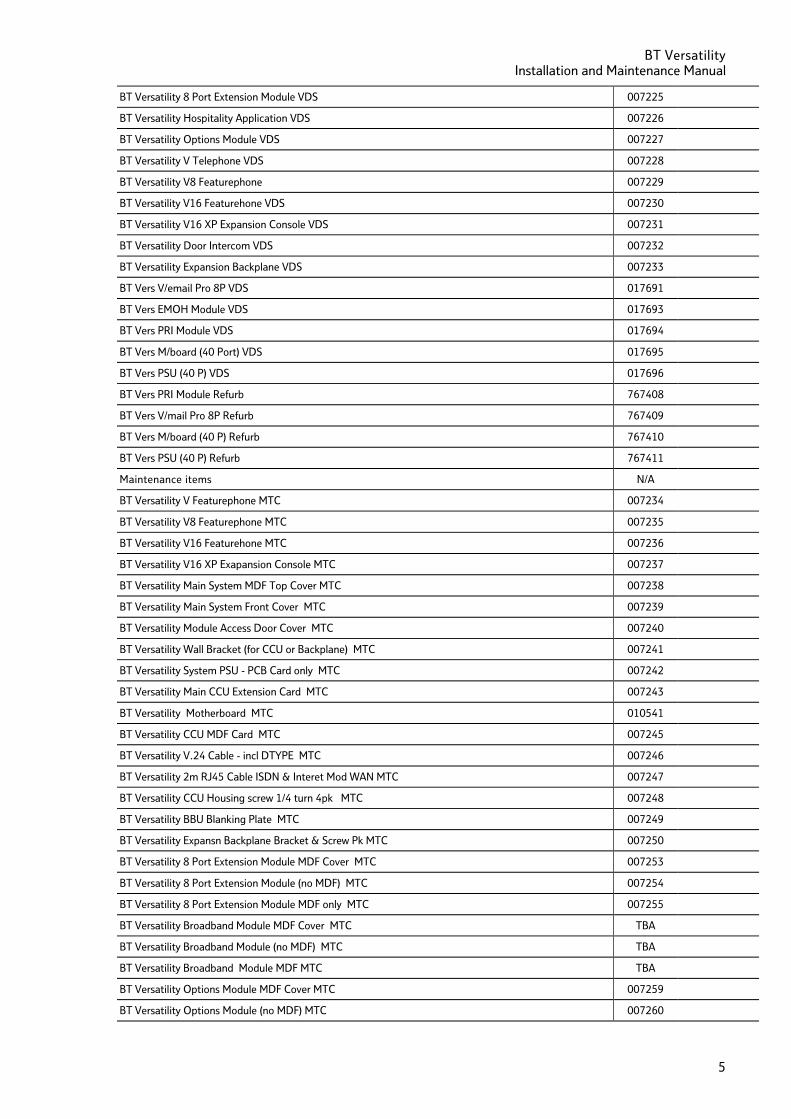
BT Versatility Installation and Maintenance Manual
5
BT Versatility 8 Port Extension Module VDS 007225
BT Versatility Hospitality Application VDS 007226
BT Versatility Options Module VDS 007227
BT Versatility V Telephone VDS 007228
BT Versatility V8 Featurephone 007229
BT Versatility V16 Featurehone VDS 007230
BT Versatility V16 XP Expansion Console VDS 007231
BT Versatility Door Intercom VDS 007232
BT Versatility Expansion Backplane VDS 007233
BT Vers V/email Pro 8P VDS 017691
BT Vers EMOH Module VDS 017693
BT Vers PRI Module VDS 017694
BT Vers M/board (40 Port) VDS 017695
BT Vers PSU (40 P) VDS 017696
BT Vers PRI Module Refurb 767408
BT Vers V/mail Pro 8P Refurb 767409
BT Vers M/board (40 P) Refurb 767410
BT Vers PSU (40 P) Refurb 767411
Maintenance items N/A
BT Versatility V Featurephone MTC 007234
BT Versatility V8 Featurephone MTC 007235
BT Versatility V16 Featurehone MTC 007236
BT Versatility V16 XP Exapansion Console MTC 007237
BT Versatility Main System MDF Top Cover MTC 007238
BT Versatility Main System Front Cover MTC 007239
BT Versatility Module Access Door Cover MTC 007240
BT Versatility Wall Bracket (for CCU or Backplane) MTC 007241
BT Versatility System PSU - PCB Card only MTC 007242
BT Versatility Main CCU Extension Card MTC 007243
BT Versatility Motherboard MTC 010541
BT Versatility CCU MDF Card MTC 007245
BT Versatility V.24 Cable - incl DTYPE MTC 007246
BT Versatility 2m RJ45 Cable ISDN & Interet Mod WAN MTC 007247
BT Versatility CCU Housing screw 1/4 turn 4pk MTC 007248
BT Versatility BBU Blanking Plate MTC 007249
BT Versatility Expansn Backplane Bracket & Screw Pk MTC 007250
BT Versatility 8 Port Extension Module MDF Cover MTC 007253
BT Versatility 8 Port Extension Module (no MDF) MTC 007254
BT Versatility 8 Port Extension Module MDF only MTC 007255
BT Versatility Broadband Module MDF Cover MTC TBA
BT Versatility Broadband Module (no MDF) MTC TBA
BT Versatility Broadband Module MDF MTC TBA
BT Versatility Options Module MDF Cover MTC 007259
BT Versatility Options Module (no MDF) MTC 007260
BT Versatility Installation and maintenance Manual
6
BT Versatility Options MDF MTC 007261
BT Versatility Mod Retentn Long 1/4 turn Screw MTC 007262
BT Versatility V16 Console to V16 Connection Cable MTC 007263
BT Versatility V16 PSU MTC 007264
BT Versatility PSTN Module MTC 007265
BT Versatility ISDN2 Module MTC 007266
BT Versatility Voice Mail Module 2 Port MTC 007267
BT Versatility Voice Mail Module 4 Port MTC 007268
BT Versatility Battery Backup Module MTC 007269
BT Versatility Door Intercom MTC 007270
Installation checklist Carry out the following steps to install the system:
FIRST, read the safety and precaution information on page 3 carefully.
SECOND, mount the Main Equipment as detailed in the section on page 7
THIRD, install the Network and Expansion modules as required
At least one Analogue Line Module must be installed to access the Analogue network.
At least one ISDN Basic Rate Module or ISDN Primary Rate Module must be installed to access the ISDN network.
A Ports module must be installed if the following is required:
• More than 8 Extensions
• More than four Analogue Lines
• More than two ISDN Basic Rate Accesses
• More than one ISDN S-bus
If no options module is installed "External Music on Hold" can be provided through the MOH Module connected to an extension. See page 34 for details on connection of the unit.
A Broadband module must be installed if an internal LAN or connection to an ADSL Line is required
A Broadband module must be installed if VoIP trunks are required.
A Broadband module requires a minimum system software version of 677
A Voice Module must be installed to provide Voicemail or Auto Attendant functionality.
The Battery Back Up Module and battery must be installed if battery back up is required.
FOURTH, cable the Extensions to the Main Equipment and install the system Featurephones and standard telephones as detailed in the Cabling Section Page 31 . This section also covers installation the following:
• Long-line Extension, • Door Intercom, • Doorstrike, • Central Bell, • External Music-on-Hold, • Public Address • V24 Interface to provide Call Logging.
FIFTH, cable the Analogue and ISDN Line connections as detailed in the cabling section Page 31.
SIXTH, commission the system and provide customer training as detailed in the Commissioning section Page 47 and 48.
BT Versatility Installation and Maintenance Manual
7
Installing the Central Control Unit
CCU Location(CCU) The CCU is intended for installation in a residential or office-type environment. It needs to be mounted at a convenient working height on a dry, flat wall. The normal height is 1.5 m from the floor to the bottom of the CCU case. Do not site the CCU where it will be subjected to excessive levels of heat, dust, damp or high humidity. Locating the equipment near sources of electromagnetic radiation, such as heavy electrical switch gear, lift machinery or electric arc welders, should be avoided. Allow at least 150 mm of free space all around the CCU for ventilation. The CCU needs to be located within two metres of a dedicated mains power supply outlet. The CCU must not share the same mains supply socket with any other electrical appliance.
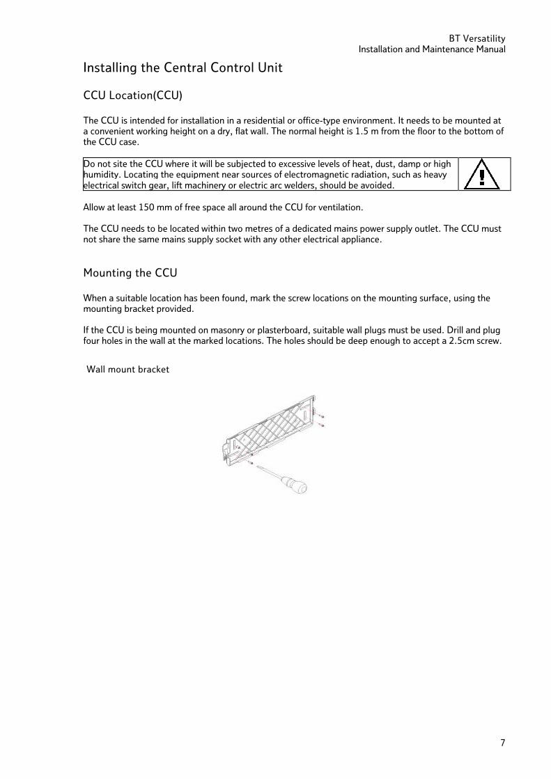
Mounting the CCU When a suitable location has been found, mark the screw locations on the mounting surface, using the mounting bracket provided. If the CCU is being mounted on masonry or plasterboard, suitable wall plugs must be used. Drill and plug four holes in the wall at the marked locations. The holes should be deep enough to accept a 2.5cm screw.
Wall mount bracket
BT Versatility Installation and maintenance Manual
8
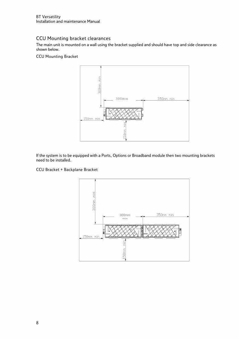
CCU Mounting bracket clearances The main unit is mounted on a wall using the bracket supplied and should have top and side clearance as shown below.
CCU Mounting Bracket
If the system is to be equipped with a Ports, Options or Broadband module then two mounting brackets need to be installed.
CCU Bracket + Backplane Bracket
300mm min
300mm min
300mm
BT Versatility Installation and Maintenance Manual
9
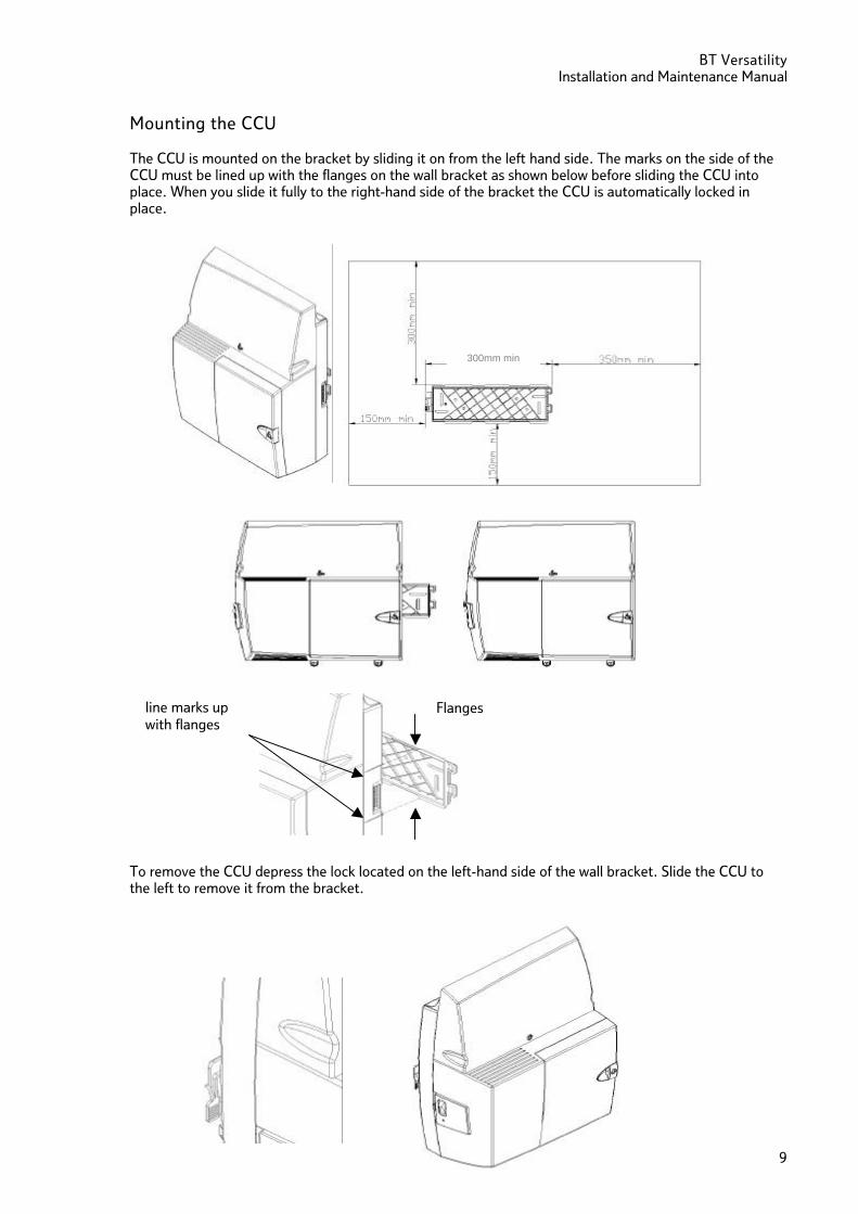
Mounting the CCU The CCU is mounted on the bracket by sliding it on from the left hand side. The marks on the side of the CCU must be lined up with the flanges on the wall bracket as shown below before sliding the CCU into place. When you slide it fully to the right-hand side of the bracket the CCU is automatically locked in place.
To remove the CCU depress the lock located on the left-hand side of the wall bracket. Slide the CCU to the left to remove it from the bracket.
300mm min
Flanges line marks up with flanges
BT Versatility Installation and maintenance Manual
10
Modules located in the CCU There are a number of modules that can be installed in the CCU.
• Analogue Line Module (Coloured Black). This provides 2 Analogue exchange lines. Up to two of these
modules can be installed in the CCU to provide two or four Analogue lines.
• Digital Line Module (Coloured Red). This card provides one ISDN 2 Basic Rate Interface. The same module is used for the network T interface and the internal S-bus. Up to two of these modules can be installed in the CCU providing one or two Basic Rate Interfaces.
There are two slots in the CCU for the Network modules. If required one slot can be equipped with an Analogue module and the other with an ISDN Module.
• Voice module 2 port, 4 port or the enhanced 8 port (Coloured Blue). Only one of these modules can
be inserted in a unit. • Primary Rate ISDN module (Coloured Yellow). This module provides for a Primary rate ISDN interface.
Up to 30 B-channels can be provided. When a Primary Rate Interface is installed, the unit can be further equipped with one or two Analogue modules or one or two ISDN Basic Rate modules to provide backup in the event of the Primary Rate interface failing.
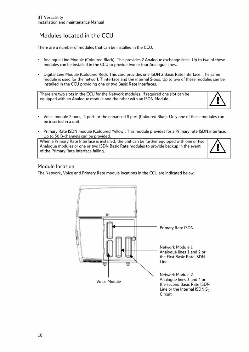
Module location The Network, Voice and Primary Rate module locations in the CCU are indicated below.
Network Module 2 Analogue lines 3 and 4 or the second Basic Rate ISDN Line or the Internal ISDN S0
Circuit
Voice Module
Primary Rate ISDN
Network Module 1 Analogue lines 1 and 2 or the First Basic Rate ISDN Line
BT Versatility Installation and Maintenance Manual
11
System Expansion
To equip the switch with more than 8 extensions or to add an Broadband or Options module, a backplane, mounted on a second wall bracket, is needed. The power must be disconnected to install the backplane or expansion modules.
Installing the Backplane wall bracket
The CCU and Backplane brackets are identical. However when both are installed the backplane bracket is inverted so that it meshes closely with the CCU bracket. Locate the second bracket and mark the screw holes. Drill and plug the holes in the wall at the marked locations. The holes should be deep enough to accept a 2.5cm screw. Mount the second bracket ensuring the two brackets are correctly interlocked and that sufficient clearance is provided on all sides.
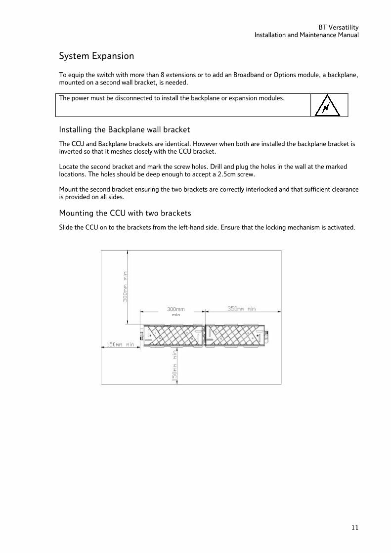
Mounting the CCU with two brackets
Slide the CCU on to the brackets from the left-hand side. Ensure that the locking mechanism is activated.
300mm min
BT Versatility Installation and maintenance Manual
12
Mounting the Backplane
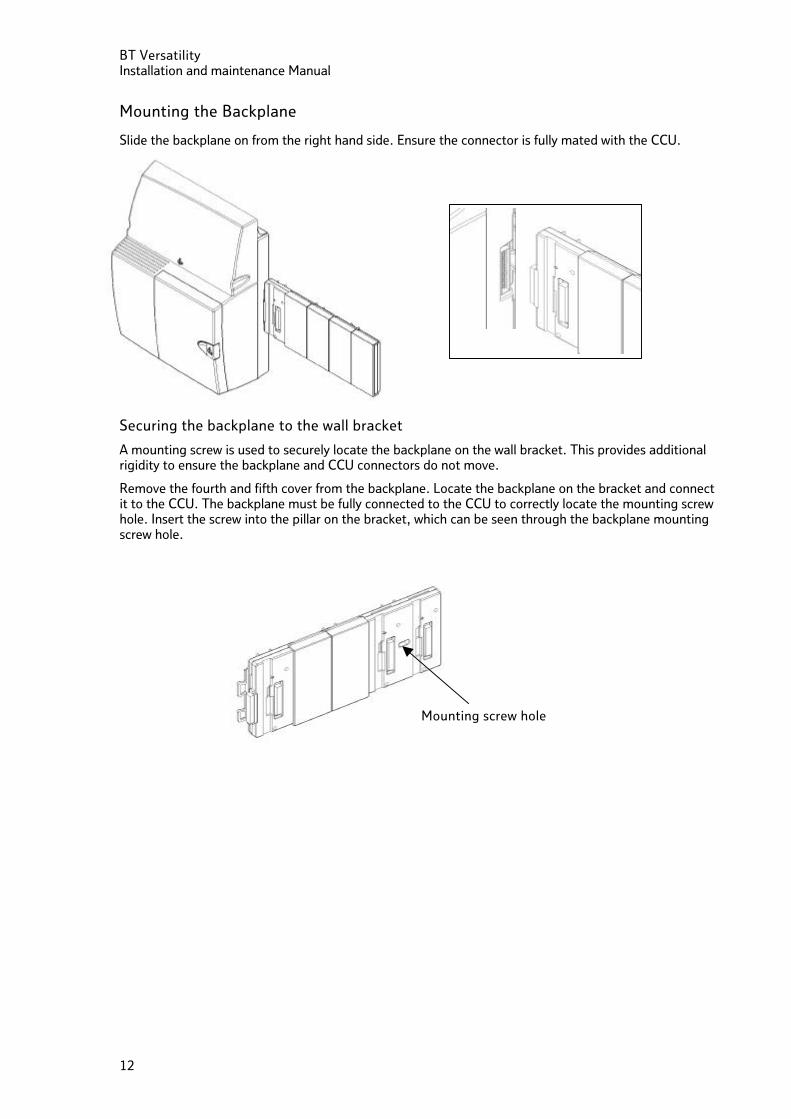
Slide the backplane on from the right hand side. Ensure the connector is fully mated with the CCU.
Securing the backplane to the wall bracket
A mounting screw is used to securely locate the backplane on the wall bracket. This provides additional rigidity to ensure the backplane and CCU connectors do not move.
Remove the fourth and fifth cover from the backplane. Locate the backplane on the bracket and connect it to the CCU. The backplane must be fully connected to the CCU to correctly locate the mounting screw hole. Insert the screw into the pillar on the bracket, which can be seen through the backplane mounting screw hole.
Mounting screw hole
BT Versatility Installation and Maintenance Manual
13
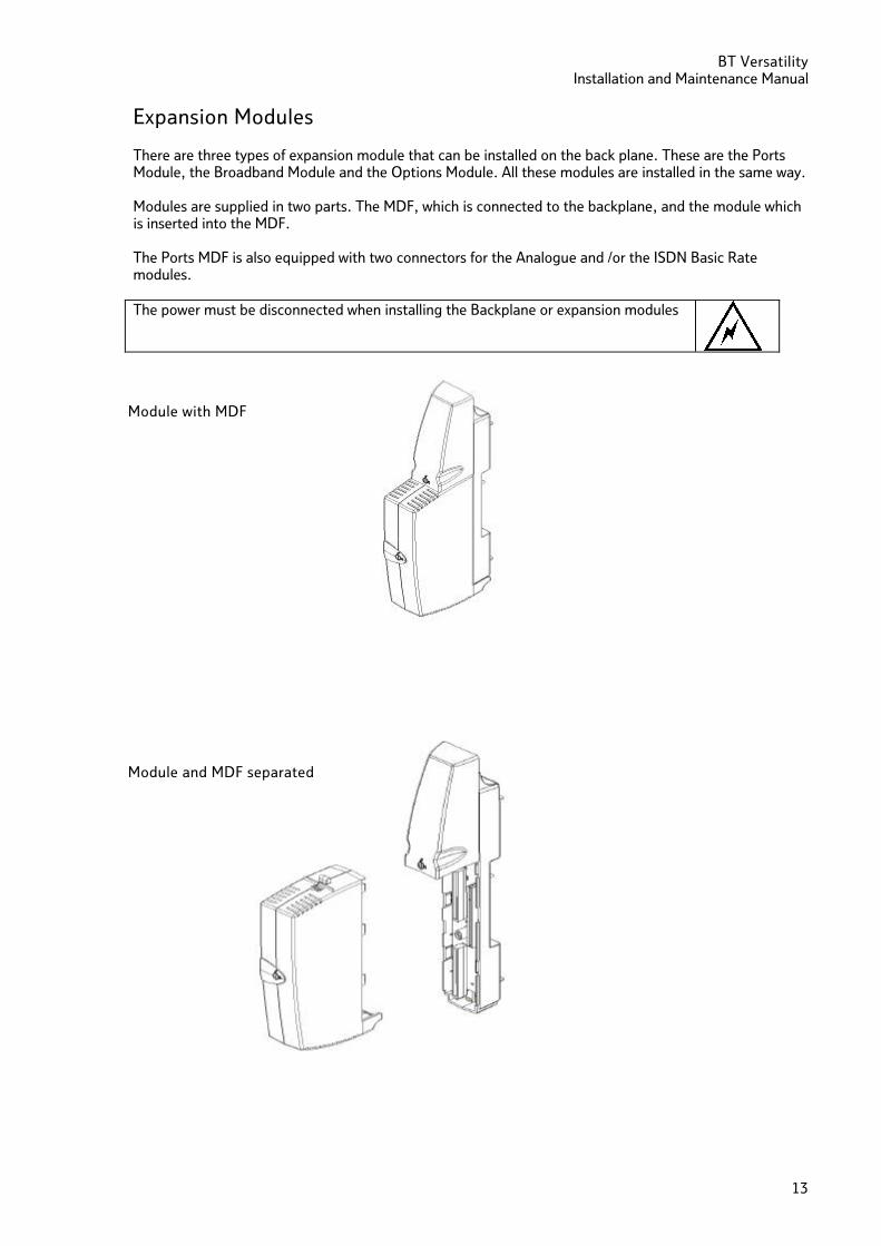
Expansion Modules
There are three types of expansion module that can be installed on the back plane. These are the Ports Module, the Broadband Module and the Options Module. All these modules are installed in the same way. Modules are supplied in two parts. The MDF, which is connected to the backplane, and the module which is inserted into the MDF. The Ports MDF is also equipped with two connectors for the Analogue and /or the ISDN Basic Rate modules. The power must be disconnected when installing the Backplane or expansion modules
Module with MDF
Module and MDF separated
BT Versatility Installation and maintenance Manual
14
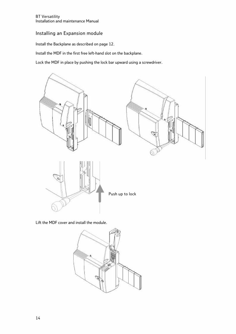
Installing an Expansion module Install the Backplane as described on page 12. Install the MDF in the first free left-hand slot on the backplane. Lock the MDF in place by pushing the lock bar upward using a screwdriver. Lift the MDF cover and install the module.
Push up to lock
BT Versatility Installation and Maintenance Manual
15
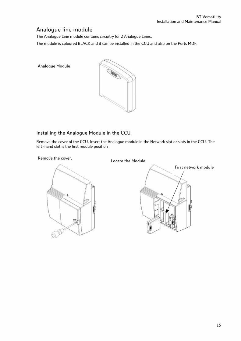
Analogue line module The Analogue Line module contains circuitry for 2 Analogue Lines.
The module is coloured BLACK and it can be installed in the CCU and also on the Ports MDF.
Installing the Analogue Module in the CCU
Remove the cover of the CCU. Insert the Analogue module in the Network slot or slots in the CCU. The left -hand slot is the first module position
Analogue Module
Locate the Module Remove the cover.
First network module
BT Versatility Installation and maintenance Manual
16
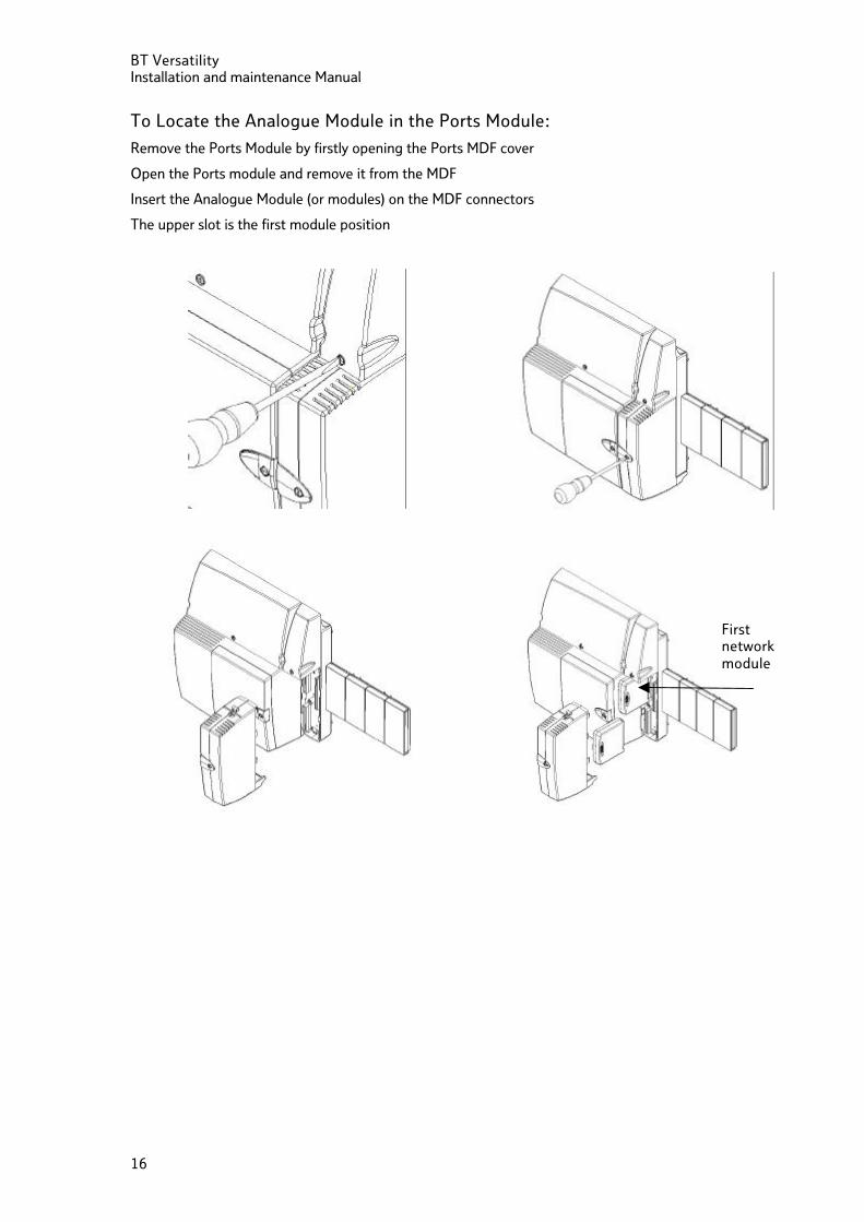
To Locate the Analogue Module in the Ports Module:
Remove the Ports Module by firstly opening the Ports MDF cover
Open the Ports module and remove it from the MDF
Insert the Analogue Module (or modules) on the MDF connectors
The upper slot is the first module position
First network module
BT Versatility Installation and Maintenance Manual
17
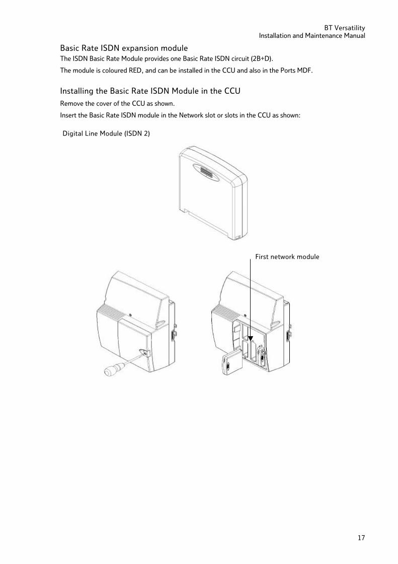
Digital Line Module (ISDN 2)
Basic Rate ISDN expansion module The ISDN Basic Rate Module provides one Basic Rate ISDN circuit (2B+D).
The module is coloured RED, and can be installed in the CCU and also in the Ports MDF.
Installing the Basic Rate ISDN Module in the CCU
Remove the cover of the CCU as shown.
Insert the Basic Rate ISDN module in the Network slot or slots in the CCU as shown:
First network module
BT Versatility Installation and maintenance Manual
18
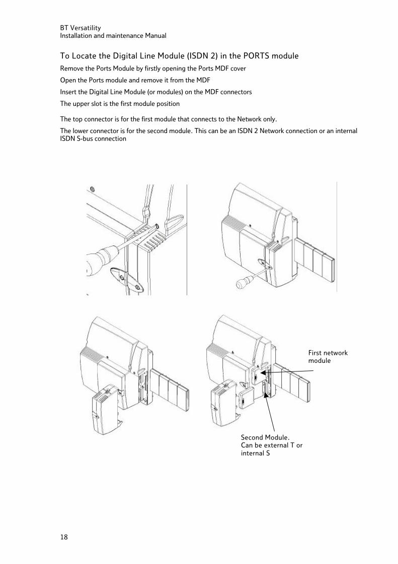
To Locate the Digital Line Module (ISDN 2) in the PORTS module
Remove the Ports Module by firstly opening the Ports MDF cover
Open the Ports module and remove it from the MDF
Insert the Digital Line Module (or modules) on the MDF connectors
The upper slot is the first module position The top connector is for the first module that connects to the Network only.
The lower connector is for the second module. This can be an ISDN 2 Network connection or an internal ISDN S-bus connection
First network module
Second Module. Can be external T or internal S
BT Versatility Installation and Maintenance Manual
19
System ISDN settings
The system can be configured with 8 Basic Rate ISDN interfaces. Half of these can be configured for internal S-bus operation.
The second interface on the CCU and each of the Ports Modules can be programmed as S-bus interfaces for ISDN to-the-desk.
T0 interface termination An ISDN bus must be terminated twice, once at the start and once at the end of the bus. The Network Terminating Equipment (NTE) will provide the termination at the start of the bus. The end termination is also provided by the NTE if the BT Versatility is directly connected to one of the NTE RJ45 sockets. If ISDN 2 extension cabling and sockets are provided between the NTE and the switch the end terminating resistor will normally be provided by an ISDN type 2 RJ45 line jack. In both of these cases BT Versatility T0 interface does not require the terminating resistor to be connected and the associated switches in the MDF associated with the T0 interface must be set to OFF (Default). NOTE: In the case of structured cabling if no end termination is provided, the associated switches in the MDF associated with the T0 interface must be set to ON.
S0 interface termination
An ISDN S-bus must be terminated twice, once at the start and once at the end of the bus. The BT Versatility S0 interface emulates the Network Terminating Equipment (NTE) and consequently is always terminated with 100 ohm resistance. In this case the switches associated with the interface in the MDF must be set ON.
BT Versatility Installation and maintenance Manual
20
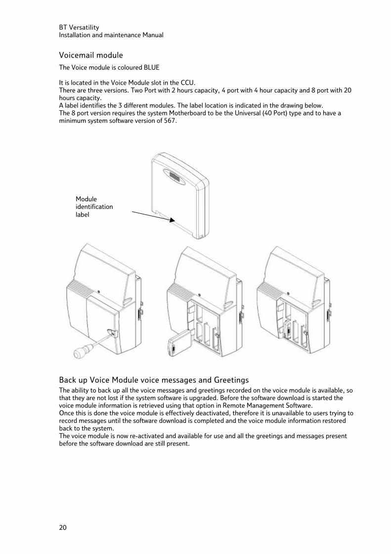
Voicemail module
The Voice module is coloured BLUE It is located in the Voice Module slot in the CCU. There are three versions. Two Port with 2 hours capacity, 4 port with 4 hour capacity and 8 port with 20 hours capacity. A label identifies the 3 different modules. The label location is indicated in the drawing below. The 8 port version requires the system Motherboard to be the Universal (40 Port) type and to have a minimum system software version of 567.
Back up Voice Module voice messages and Greetings The ability to back up all the voice messages and greetings recorded on the voice module is available, so that they are not lost if the system software is upgraded. Before the software download is started the voice module information is retrieved using that option in Remote Management Software. Once this is done the voice module is effectively deactivated, therefore it is unavailable to users trying to record messages until the software download is completed and the voice module information restored back to the system. The voice module is now re-activated and available for use and all the greetings and messages present before the software download are still present.
Module identification label
BT Versatility Installation and Maintenance Manual
21
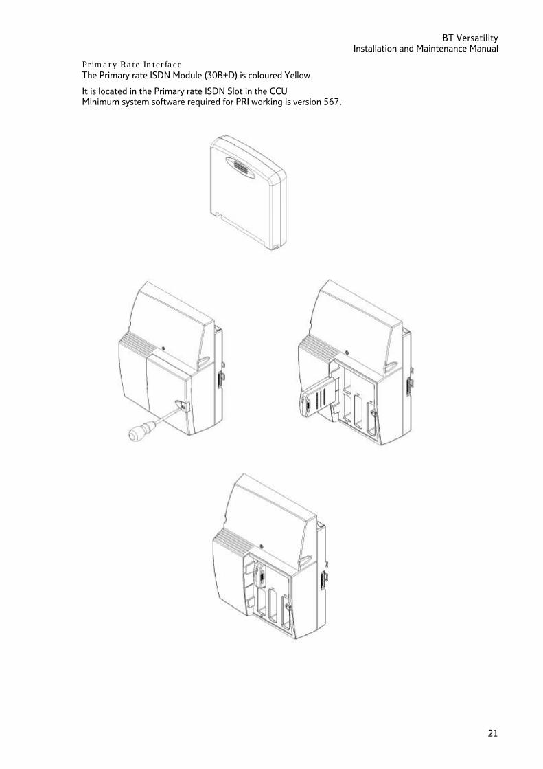
Primary Rate Interface The Primary rate ISDN Module (30B+D) is coloured Yellow
It is located in the Primary rate ISDN Slot in the CCU Minimum system software required for PRI working is version 567.
BT Versatility Installation and maintenance Manual
22
Connecting the battery backup unit to the system
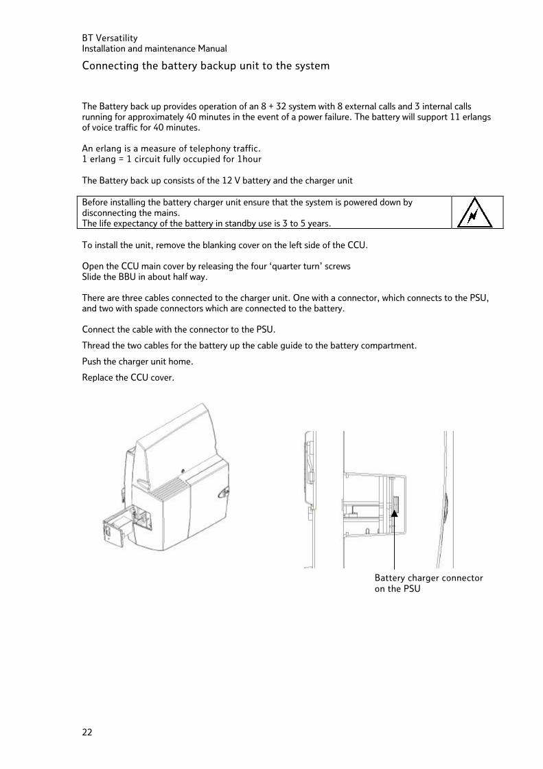
The Battery back up provides operation of an 8 + 32 system with 8 external calls and 3 internal calls running for approximately 40 minutes in the event of a power failure. The battery will support 11 erlangs of voice traffic for 40 minutes. An erlang is a measure of telephony traffic. 1 erlang = 1 circuit fully occupied for 1hour
The Battery back up consists of the 12 V battery and the charger unit Before installing the battery charger unit ensure that the system is powered down by disconnecting the mains. The life expectancy of the battery in standby use is 3 to 5 years. To install the unit, remove the blanking cover on the left side of the CCU. Open the CCU main cover by releasing the four ‘quarter turn’ screws Slide the BBU in about half way. There are three cables connected to the charger unit. One with a connector, which connects to the PSU, and two with spade connectors which are connected to the battery. Connect the cable with the connector to the PSU.
Thread the two cables for the battery up the cable guide to the battery compartment.
Push the charger unit home.
Replace the CCU cover.
Battery charger connector on the PSU
BT Versatility Installation and Maintenance Manual
23
Connecting the Battery
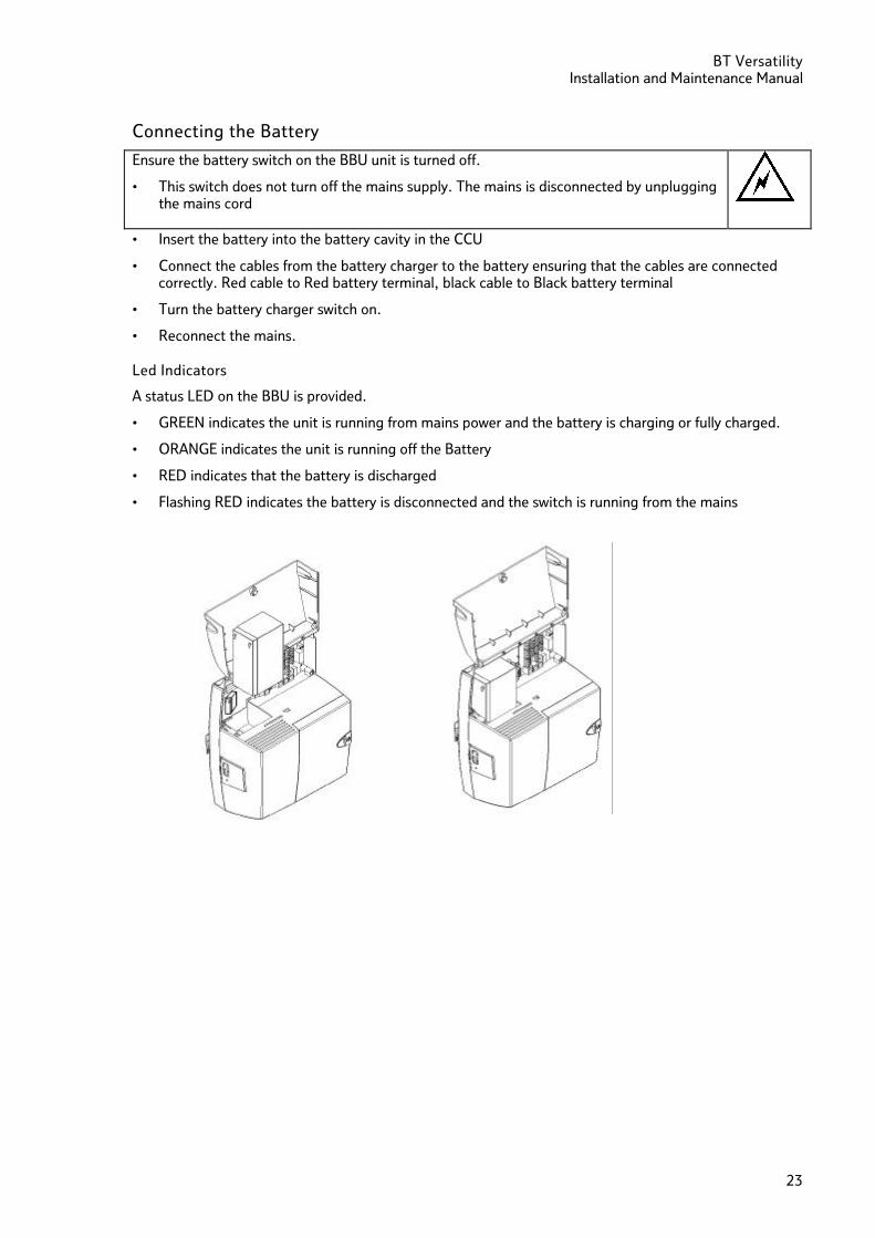
Ensure the battery switch on the BBU unit is turned off.
• This switch does not turn off the mains supply. The mains is disconnected by unplugging the mains cord
• Insert the battery into the battery cavity in the CCU
• Connect the cables from the battery charger to the battery ensuring that the cables are connected correctly. Red cable to Red battery terminal, black cable to Black battery terminal
• Turn the battery charger switch on.
• Reconnect the mains.
Led Indicators
A status LED on the BBU is provided.
• GREEN indicates the unit is running from mains power and the battery is charging or fully charged.
• ORANGE indicates the unit is running off the Battery
• RED indicates that the battery is discharged
• Flashing RED indicates the battery is disconnected and the switch is running from the mains
BT Versatility Installation and maintenance Manual
24
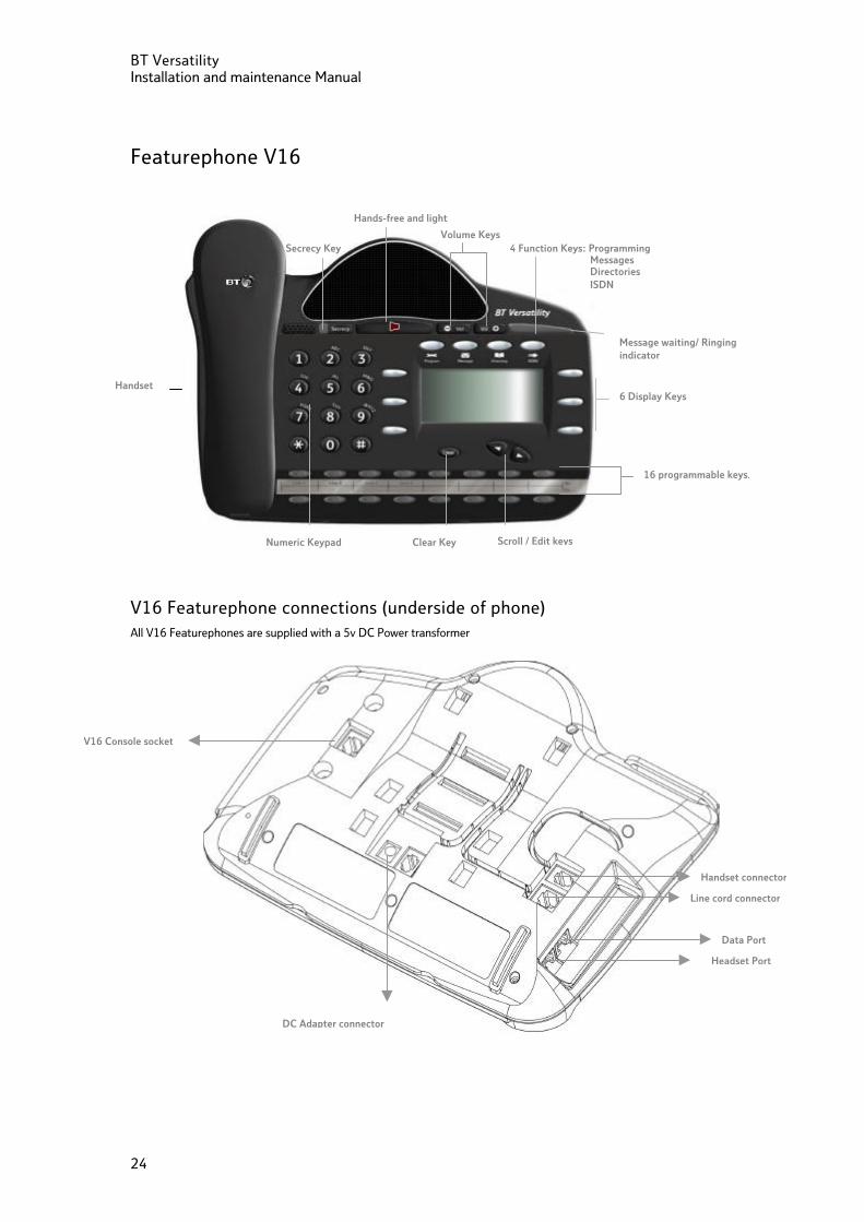
Featurephone V16
V16 Featurephone connections (underside of phone) All V16 Featurephones are supplied with a 5v DC Power transformer
Handset connector
Line cord connector
DC Adapter connector
Data Port
Headset Port
V16 Console socket
6 Display Keys
16 programmable keys.
Volume Keys
Message waiting/ Ringing indicator
Clear Key Scroll / Edit keys Numeric Keypad
Secrecy Key 4 Function Keys: Programming Messages Directories ISDN
Hands-free and light
Handset
BT Versatility Installation and Maintenance Manual
25
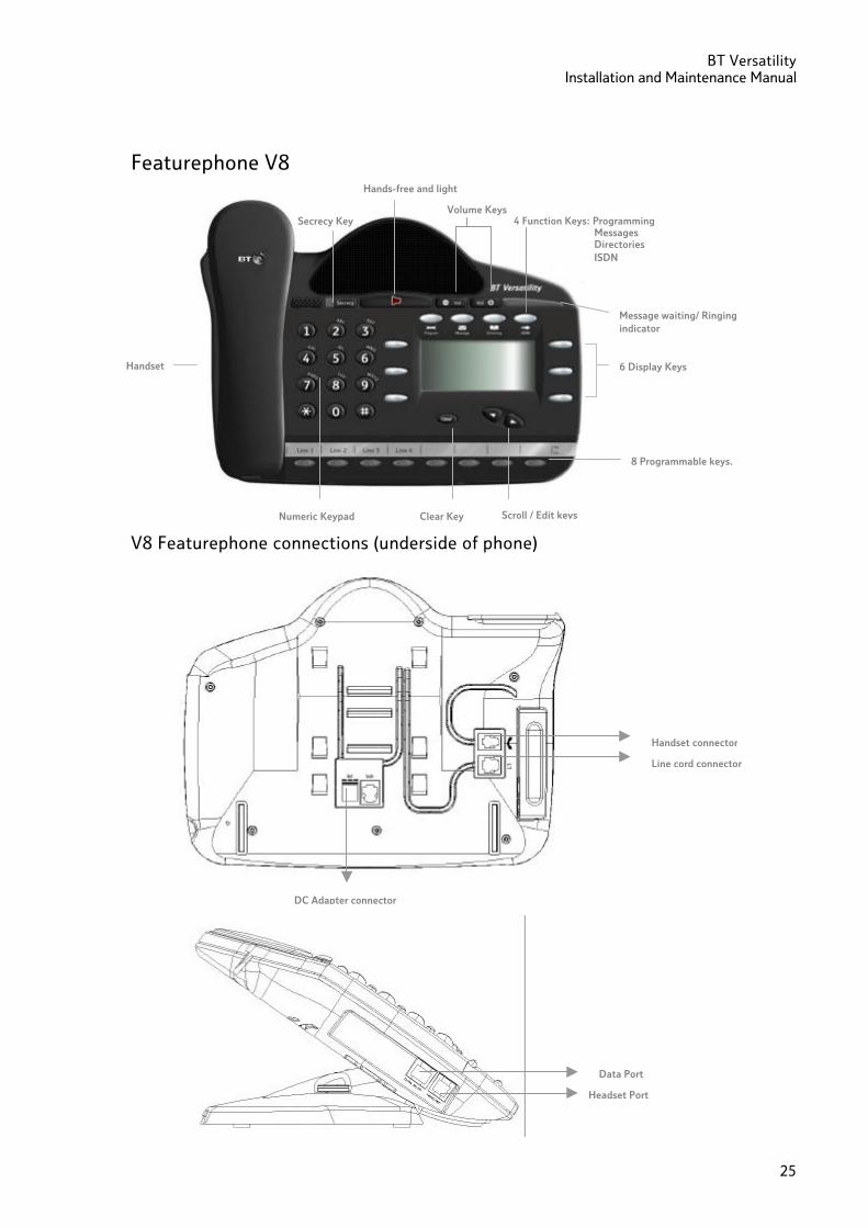
Featurephone V8
V8 Featurephone connections (underside of phone)
Handset connector
Line cord connector
DC Adapter connector
Headset Port
Data Port
8 Programmable keys.
6 Display Keys
Volume Keys
Message waiting/ Ringing indicator
Clear Key Scroll / Edit keys Numeric Keypad
Handset
Secrecy Key 4 Function Keys: Programming Messages Directories ISDN
Hands-free and light
BT Versatility Installation and maintenance Manual
26
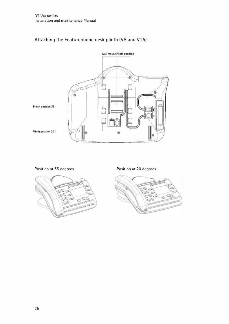
Attaching the Featurephone desk plinth (V8 and V16)
Position at 35 degrees Position at 20 degrees
Wall mount Plinth position
Plinth position 20 °
Plinth position 35°
BT Versatility Installation and Maintenance Manual
27
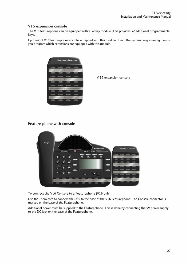
V16 expansion console The V16 featurephone can be equipped with a 32 key module. This provides 32 additional programmable keys.
Up to eight V16 featurephones can be equipped with this module. From the system programming menus you program which extensions are equipped with this module.
Feature phone with console To connect the V16 Console to a Featurephone (V16 only)
Use the 15cm cord to connect the DSS to the base of the V16 Featurephone. The Console connector is marked on the base of the Featurephone.
Additional power must be supplied to the Featurephone. This is done by connecting the 5V power supply to the DC jack on the base of the Featurephone.
V 16 expansion console
BT Versatility Installation and maintenance Manual
28
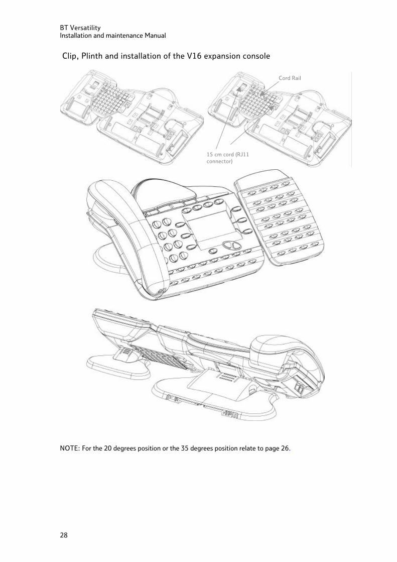
Clip, Plinth and installation of the V16 expansion console
NOTE: For the 20 degrees position or the 35 degrees position relate to page 26.
15 cm cord (RJ11 connector)
Cord Rail
BT Versatility Installation and Maintenance Manual
29
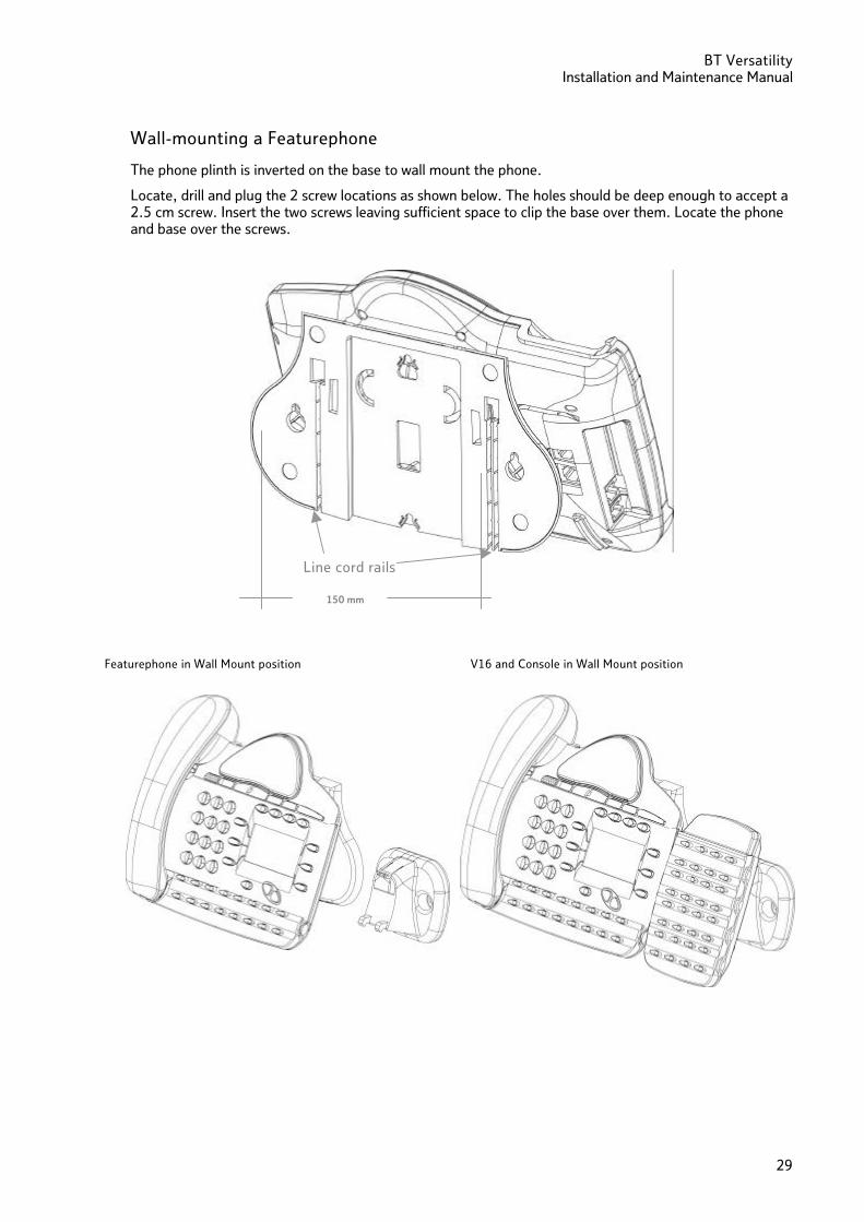
Wall-mounting a Featurephone
The phone plinth is inverted on the base to wall mount the phone.
Locate, drill and plug the 2 screw locations as shown below. The holes should be deep enough to accept a 2.5 cm screw. Insert the two screws leaving sufficient space to clip the base over them. Locate the phone and base over the screws.
150 mm
Line cord rails
V16 and Console in Wall Mount position Featurephone in Wall Mount position
BT Versatility Installation and maintenance Manual
30
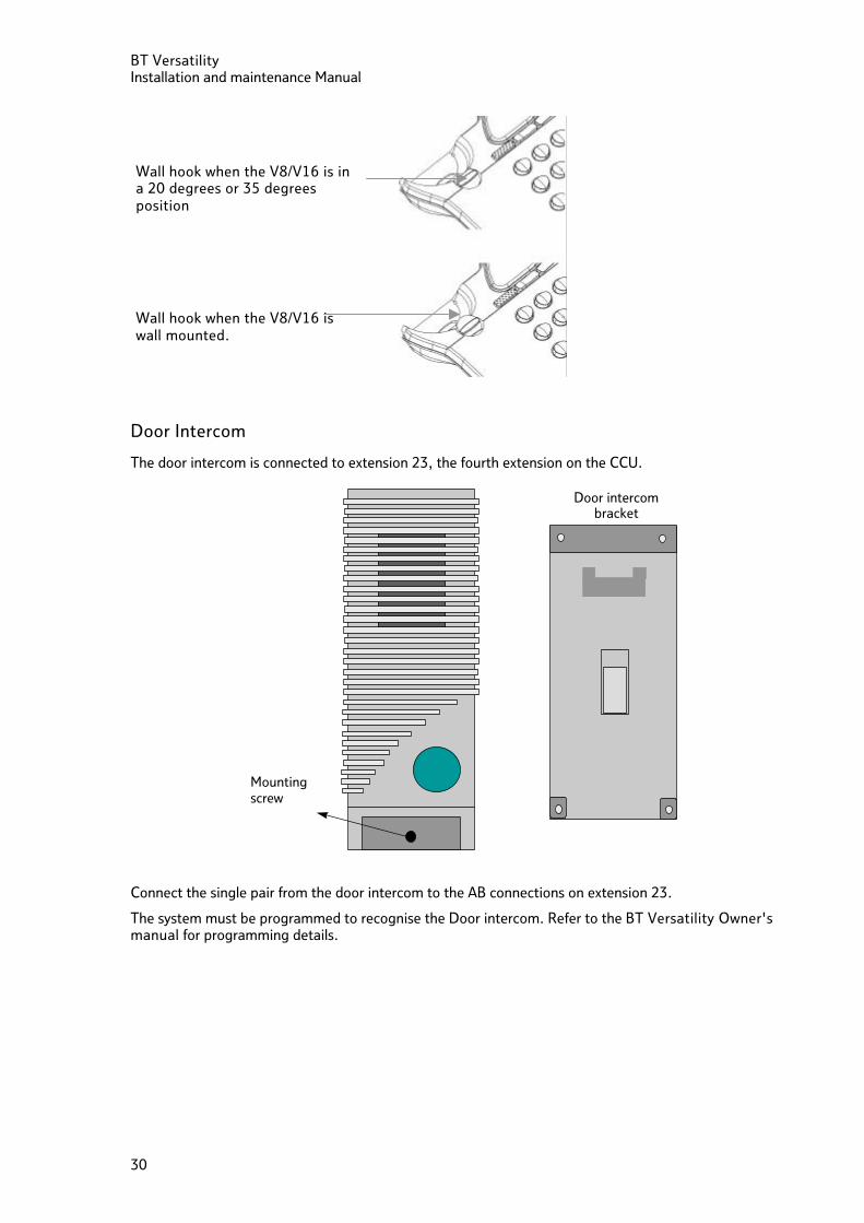
Door Intercom
The door intercom is connected to extension 23, the fourth extension on the CCU.
Mountingscrew
Door intercombracket
Connect the single pair from the door intercom to the AB connections on extension 23.
The system must be programmed to recognise the Door intercom. Refer to the BT Versatility Owner's manual for programming details.
Wall hook when the V8/V16 is in a 20 degrees or 35 degrees position
Wall hook when the V8/V16 is wall mounted.
BT Versatility Installation and Maintenance Manual
31
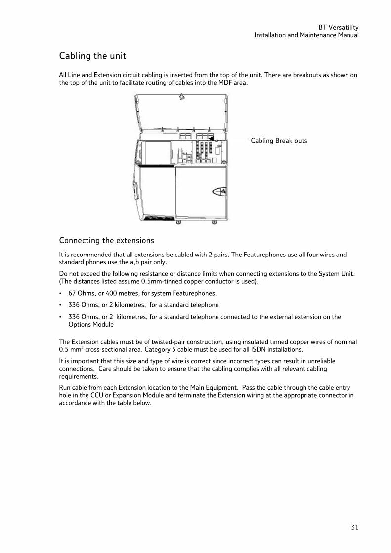
Cabling the unit
All Line and Extension circuit cabling is inserted from the top of the unit. There are breakouts as shown on the top of the unit to facilitate routing of cables into the MDF area.
Connecting the extensions
It is recommended that all extensions be cabled with 2 pairs. The Featurephones use all four wires and standard phones use the a,b pair only.
Do not exceed the following resistance or distance limits when connecting extensions to the System Unit. (The distances listed assume 0.5mm-tinned copper conductor is used).
• 67 Ohms, or 400 metres, for system Featurephones.
• 336 Ohms, or 2 kilometres, for a standard telephone
• 336 Ohms, or 2 kilometres, for a standard telephone connected to the external extension on the Options Module
The Extension cables must be of twisted-pair construction, using insulated tinned copper wires of nominal 0.5 mm2 cross-sectional area. Category 5 cable must be used for all ISDN installations.
It is important that this size and type of wire is correct since incorrect types can result in unreliable connections. Care should be taken to ensure that the cabling complies with all relevant cabling requirements.
Run cable from each Extension location to the Main Equipment. Pass the cable through the cable entry hole in the CCU or Expansion Module and terminate the Extension wiring at the appropriate connector in accordance with the table below.
Cabling Break outs
BT Versatility Installation and maintenance Manual
32
Four wires per Extension are connected at the Main Equipment. Spare wires must be neatly laid back away from the connectors. To prevent cross talk or interference, cable pairs should not be split or the spare wire of cable pairs used. All Extensions should connect into standard line jack units. Extension cabling should not be exposed to high voltage surges, (for example, surges induced by lightning or neighbouring high current-carrying cables). If this is a possibility external protection of the Main Equipment and Extensions using ‘earthed line surge protectors’ is essential.
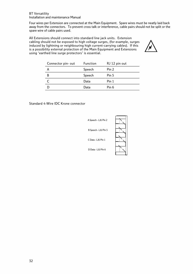
Connector pin- out Function RJ 12 pin out
A Speech Pin 2
B Speech Pin 5
C Data Pin 1
D Data Pin 6
Standard 4-Wire IDC Krone connector
A Speech - LJU Pin 2
B Speech - LJU Pin 5
C Data - LJU Pin 1
D Data - LJU Pin 6
BT Versatility Installation and Maintenance Manual
33
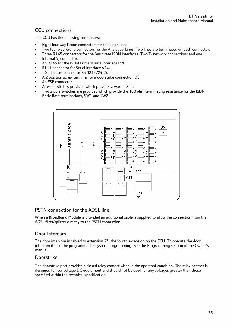
CCU connections
The CCU has the following connectors:-
• Eight four way Krone connectors for the extensions • Two four way Krone connectors for the Analogue Lines. Two lines are terminated on each connector. • Three RJ 45 connectors for the Basic rate ISDN interfaces. Two T0 network connections and one
Internal S0 connector. • An RJ 45 for the ISDN Primary Rate interface PRI. • RJ 11 connector for Serial Interface V24-1. • 1 Serial port connector RS 323 (V24-2). • A 2 position screw terminal for a doorstrike connection DS • An ESP connector. • A reset switch is provided which provides a warm reset. • Two 2 pole switches are provided which provide the 100 ohm terminating resistance for the ISDN
Basic Rate terminations, SW1 and SW2.
PSTN connection for the ADSL line
When a Broadband Module is provided an additional cable is supplied to allow the connection from the ADSL filter/splitter directly to the PSTN connection.
Door Intercom
The door intercom is cabled to extension 23, the fourth extension on the CCU. To operate the door intercom it must be programmed in system programming. See the Programming section of the Owner’s manual.
Doorstrike
The doorstrike port provides a closed relay contact when in the operated condition. The relay contact is designed for low voltage DC equipment and should not be used for any voltages greater than those specified within the technical specification.
BT Versatility Installation and maintenance Manual
34
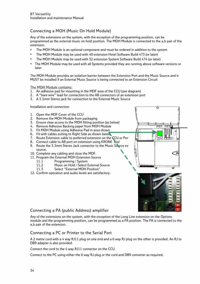
Connecting a MOH (Music On Hold Module)
Any of the extensions on the system, with the exception of the programming position, can be programmed as the external music on hold position. The MOH Module is connected to the a,b pair of the extension. • The MOH Module is an optional component and must be ordered in addition to the system • The MOH Module may be used with 40 extension Hotel Software Build 473 (or later) • The MOH Module may be used with 32 extension System Software Build 474 (or later) • The MOH Module may be used with all Systems provided they are running above software versions or
later The MOH Module provides an isolation barrier between the Extension Port and the Music Source and it MUST be installed if an External Music Source is being connected to an Extension Circuit The MOH Module contains: 1. An adhesive pad for mounting in the MDF area of the CCU (see diagram) 2. A “bare wire” lead for connection to the AB connectors of an extension port 3. A 3.5mm Stereo jack for connection to the External Music Source Installation and connection 1. Open the MDF Cover of the CCU 2. Remove the MOH Module from packaging 3. Ensure clear access to the MOH fitting position (as below) 4. Remove Adhesive Backing paper from MOH Module 5. Fit MOH Module using Adhesive Pad in area shown 6. Fit with cables exiting to Right Side as shown below 7. Route Extension cable to preferred extension on the CCU or Ports module 8. Connect cable to AB port on extension using KRONE tool 9. Route the 3.5mm Stereo Jack connector to the Music Source external to the system, and connect
source. 10. Complete any cabling and close the MDF. 11. Program the External MOH Extension Source
11.1 Programming / System 11.2 Music on Hold / Select External Source 11.3 Select “External MOH Position”
12. Confirm operation and audio levels are satisfactory.
Connecting a PA (public Address) amplifier
Any of the extensions on the system, with the exception of the Long Line extension on the Options module and the programming position, can be programmed as a PA position. The PA is connected to the a,b pair of the extension.
Connecting a PC or Printer to the Serial Port
A 2 metre cord with a 4 way RJ11 plug on one end and a 6 way RJ plug on the other is provided. An RJ to DB9 adapter is also provided.
Connect the cord to the 4 way RJ11 connector on the CCU.
Connect to the PC using either the 6 way RJ plug or the cord and DB9 converter as required.
BT Versatility Installation and Maintenance Manual
35
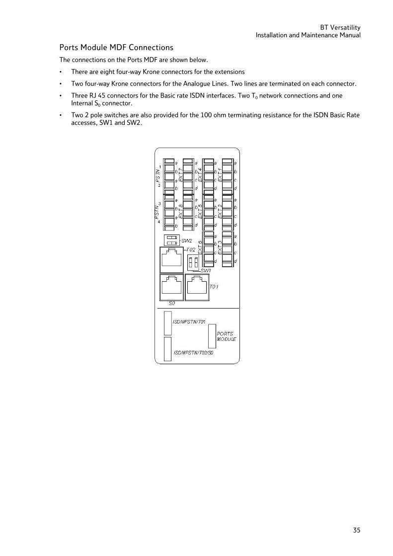
Ports Module MDF Connections
The connections on the Ports MDF are shown below.
• There are eight four-way Krone connectors for the extensions
• Two four-way Krone connectors for the Analogue Lines. Two lines are terminated on each connector.
• Three RJ 45 connectors for the Basic rate ISDN interfaces. Two T0 network connections and one Internal S0 connector.
• Two 2 pole switches are also provided for the 100 ohm terminating resistance for the ISDN Basic Rate accesses, SW1 and SW2.
BT Versatility Installation and maintenance Manual
36
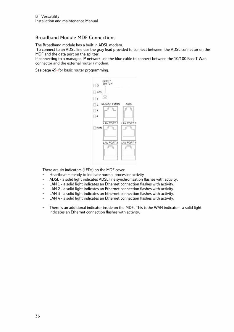
Broadband Module MDF Connections
The Broadband module has a built in ADSL modem. To connect to an ADSL line use the gray lead provided to connect between the ADSL connector on the MDF and the data port on the splitter. If connecting to a managed IP network use the blue cable to connect between the 10/100 BaseT Wan connector and the external router / modem.
See page 49 for basic router programming.
There are six indicators (LEDs) on the MDF cover. • Heartbeat – steady to indicate normal processor activity • ADSL - a solid light indicates ADSL line synchronisation flashes with activity. • LAN 1 - a solid light indicates an Ethernet connection flashes with activity. • LAN 2 - a solid light indicates an Ethernet connection flashes with activity. • LAN 3 - a solid light indicates an Ethernet connection flashes with activity. • LAN 4 - a solid light indicates an Ethernet connection flashes with activity.
• There is an additional indicator inside on the MDF. This is the WAN indicator - a solid light
indicates an Ethernet connection flashes with activity.
BT Versatility Installation and Maintenance Manual
37
Options Module MDF Connections
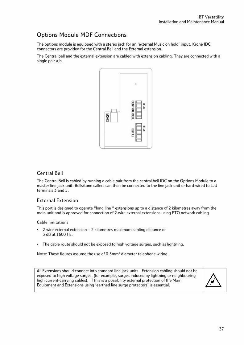
The options module is equipped with a stereo jack for an ‘external Music on hold’ input. Krone IDC connectors are provided for the Central Bell and the External extension.
The Central bell and the external extension are cabled with extension cabling. They are connected with a single pair a,b.
Central Bell
The Central Bell is cabled by running a cable pair from the central bell IDC on the Options Module to a master line jack unit. Bells/tone callers can then be connected to the line jack unit or hard-wired to LJU terminals 3 and 5.
External Extension
This port is designed to operate “long line “ extensions up to a distance of 2 kilometres away from the main unit and is approved for connection of 2-wire external extensions using PTO network cabling. Cable limitations
• 2-wire external extension = 2 kilometres maximum cabling distance or 3 dB at 1600 Hz.
• The cable route should not be exposed to high voltage surges, such as lightning.
Note: These figures assume the use of 0.5mm2 diameter telephone wiring. All Extensions should connect into standard line jack units. Extension cabling should not be exposed to high voltage surges, (for example, surges induced by lightning or neighbouring high current-carrying cables). If this is a possibility external protection of the Main Equipment and Extensions using ‘earthed line surge protectors’ is essential.
BT Versatility Installation and maintenance Manual
38
Expanding an Existing system
Modules may be removed and re-inserted in a system without disconnecting the power. See page 39.
However if additional modules are being installed in a working system it is necessary to power the system down before installing an MDF or Backplane.
If additional network modules are to be installed in spare slots, the system needs to be reset before the switch recognises the new modules.
Installing an additional Network (Analogue or ISDN) module
Modules can be installed in spare slots on the system without powering the system down. However the module will not be activated until the system is reset. This can be achieved by pressing the reset button on the CCU MDF. Pressing the reset button will invoke a warm reset and clear any calls in progress
Installing additional modules
The system must be powered down before installing an additional MDF on the Backplane. When the MDF is installed it is recommended that the Module, and any additional Network modules that may be required, be installed before the system is powered up. When the system is powered up the additional modules will be recognised by the system.
The power must be disconnected before installing an MDF or Backplane. If Battery Back up is provided ensure the BBU switch is off and the mains is disconnected.
BT Versatility Installation and Maintenance Manual
39
Maintenance procedures
Faults can be rectified on site by replacing faulty modules or PCBs
Hot Swapping faulty modules
The Network modules can be replaced without powering the system down.
If a Network module is replaced by the same type of module e.g. Analogue by Analogue, the switch will return to normal operation when the new module is inserted
If a Network Module is to be replaced by a different type of Network Module (e.g. an Analogue module replaced by an ISDN module) the system must be reset, by pressing the reset switch in the CCU MDF area, so that the system can recognise the new module type.
If an ISDN line is replacing an analogue line ensure the analogue line cable is disconnected before connecting the ISDN Line or installing the module. The same applies if an analogue line replaces an ISDN line.
The Ports Modules can be removed and replaced without powering down the system
The Options Module can be removed and replaced without powering down the system
The Voice module can be removed and replaced without powering down the system.
When a voice module is replaced all recorded messages and greetings are lost.
The Internet Module can be removed and replaced without powering down the system.
The Broadband Module can be removed and replaced without powering down the system.
The Primary Rate ISDN Module can be removed and replaced without powering down the system.
The MOH Module can be removed and replaced without powering down the system.
BT Versatility Installation and maintenance Manual
40
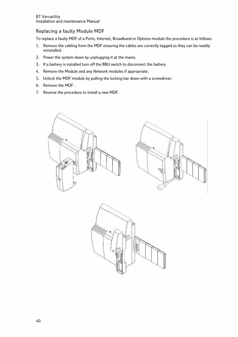
Replacing a faulty Module MDF
To replace a faulty MDF of a Ports, Internet, Broadband or Options module the procedure is as follows:
1. Remove the cabling from the MDF ensuring the cables are correctly tagged so they can be readily reinstalled.
2. Power the system down by unplugging it at the mains.
3. If a battery is installed turn off the BBU switch to disconnect the battery.
4. Remove the Module and any Network modules if appropriate.
5. Unlock the MDF module by pulling the locking bar down with a screwdriver.
6. Remove the MDF .
7. Reverse the procedure to install a new MDF.
BT Versatility Installation and Maintenance Manual
41
Replacing Faulty PCBs
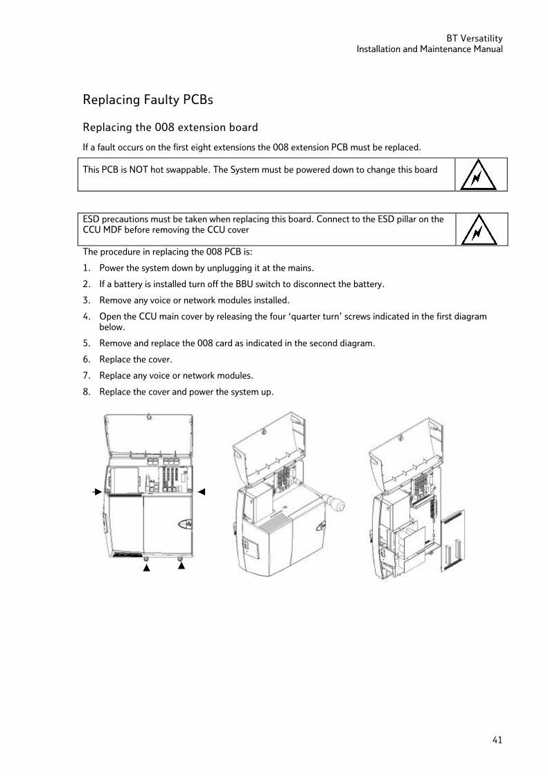
Replacing the 008 extension board
If a fault occurs on the first eight extensions the 008 extension PCB must be replaced.
This PCB is NOT hot swappable. The System must be powered down to change this board
ESD precautions must be taken when replacing this board. Connect to the ESD pillar on the CCU MDF before removing the CCU cover The procedure in replacing the 008 PCB is:
1. Power the system down by unplugging it at the mains.
2. If a battery is installed turn off the BBU switch to disconnect the battery.
3. Remove any voice or network modules installed.
4. Open the CCU main cover by releasing the four ‘quarter turn’ screws indicated in the first diagram below.
5. Remove and replace the 008 card as indicated in the second diagram.
6. Replace the cover.
7. Replace any voice or network modules.
8. Replace the cover and power the system up.
BT Versatility Installation and maintenance Manual
42
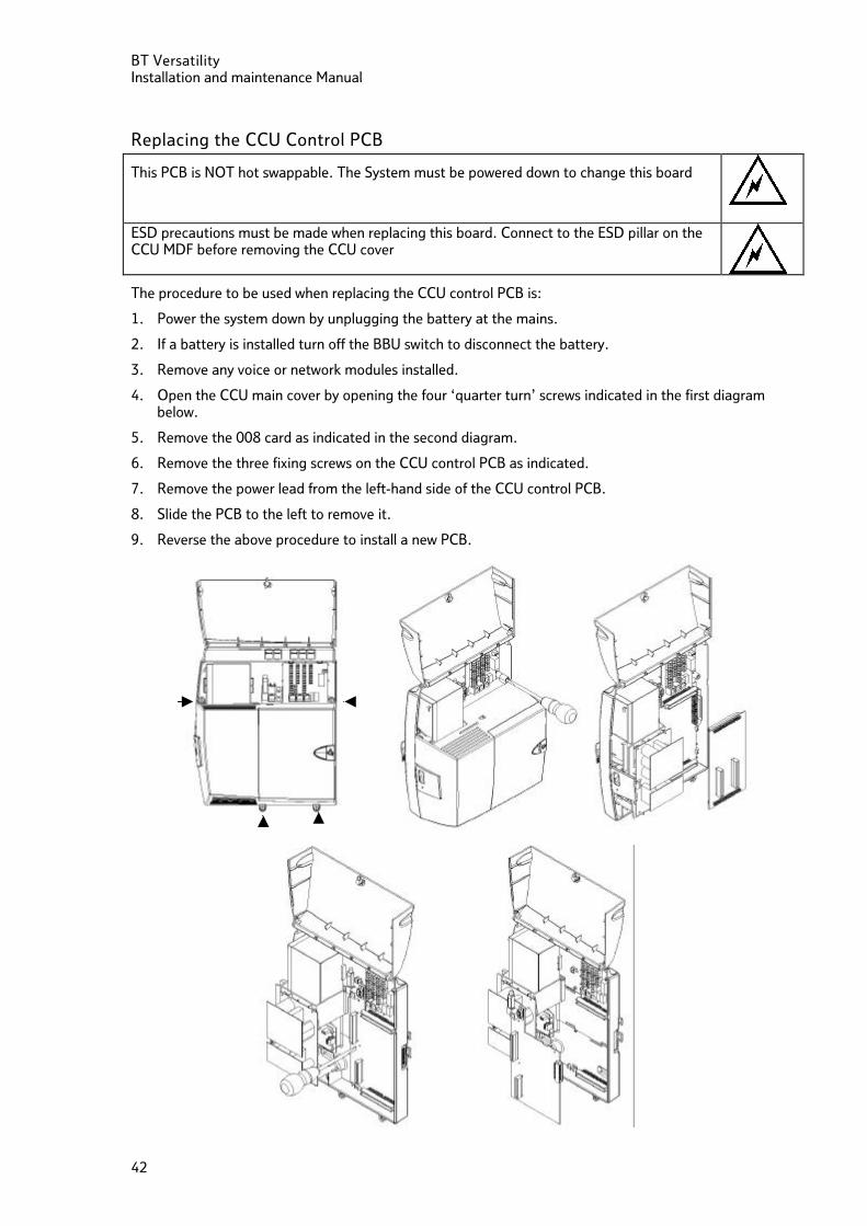
Replacing the CCU Control PCB
This PCB is NOT hot swappable. The System must be powered down to change this board
ESD precautions must be made when replacing this board. Connect to the ESD pillar on the CCU MDF before removing the CCU cover
The procedure to be used when replacing the CCU control PCB is:
1. Power the system down by unplugging the battery at the mains.
2. If a battery is installed turn off the BBU switch to disconnect the battery.
3. Remove any voice or network modules installed.
4. Open the CCU main cover by opening the four ‘quarter turn’ screws indicated in the first diagram below.
5. Remove the 008 card as indicated in the second diagram.
6. Remove the three fixing screws on the CCU control PCB as indicated.
7. Remove the power lead from the left-hand side of the CCU control PCB.
8. Slide the PCB to the left to remove it.
9. Reverse the above procedure to install a new PCB.
BT Versatility Installation and Maintenance Manual
43
Power supply unit spare fuse
A spare mains fuse is located in the Power supply unit. It is in a holder directly below the installed fuse (3.15A T).
If there is no power being supplied to the unit check if the fuse is blown
1. Power the system down by unplugging it at the mains.
2. If a battery is installed turn off the BBU switch to disconnect the battery.
3. Remove any voice or network modules.
4. Open the CCU main cover by opening the four ‘quarter turn’ screws indicated in the first diagram below.
5. Check the fuse on the Power supply
6. If it is blown replace it with the spare fuse
Note: The spare fuse should only be used to replace the installed mains fuse type 3.15A T and should not be used to replace any other fuse on the power supply board.
BT Versatility Installation and maintenance Manual
44
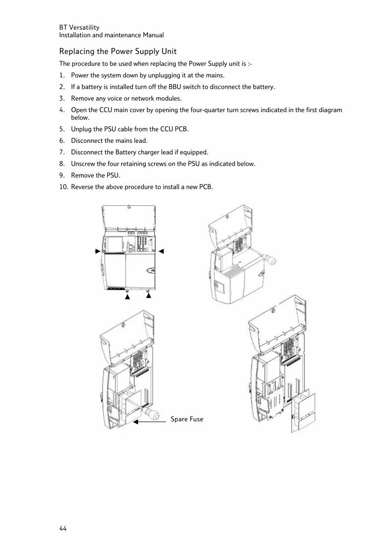
Replacing the Power Supply Unit
The procedure to be used when replacing the Power Supply unit is :-
1. Power the system down by unplugging it at the mains.
2. If a battery is installed turn off the BBU switch to disconnect the battery.
3. Remove any voice or network modules.
4. Open the CCU main cover by opening the four-quarter turn screws indicated in the first diagram below.
5. Unplug the PSU cable from the CCU PCB.
6. Disconnect the mains lead.
7. Disconnect the Battery charger lead if equipped.
8. Unscrew the four retaining screws on the PSU as indicated below.
9. Remove the PSU.
10. Reverse the above procedure to install a new PCB.
Spare Fuse
BT Versatility Installation and Maintenance Manual
45
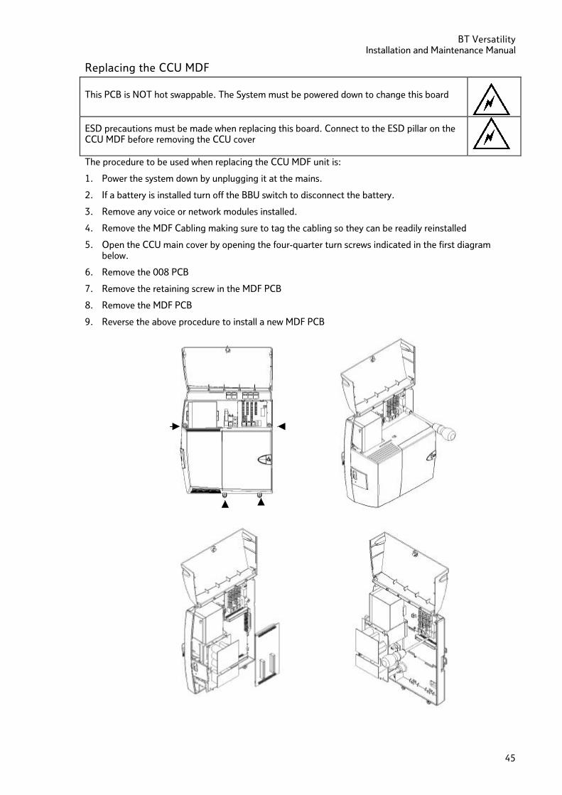
Replacing the CCU MDF
This PCB is NOT hot swappable. The System must be powered down to change this board
ESD precautions must be made when replacing this board. Connect to the ESD pillar on the CCU MDF before removing the CCU cover
The procedure to be used when replacing the CCU MDF unit is:
1. Power the system down by unplugging it at the mains.
2. If a battery is installed turn off the BBU switch to disconnect the battery.
3. Remove any voice or network modules installed.
4. Remove the MDF Cabling making sure to tag the cabling so they can be readily reinstalled
5. Open the CCU main cover by opening the four-quarter turn screws indicated in the first diagram below.
6. Remove the 008 PCB
7. Remove the retaining screw in the MDF PCB
8. Remove the MDF PCB
9. Reverse the above procedure to install a new MDF PCB
BT Versatility Installation and maintenance Manual
46
Power fail When planning the extension wiring for the system, consideration should be given to the use and location of Featurephones and 2-wire extensions.
Analogue
In the event of a total system power failure, at least 50% of the equipped lines are switched to extensions. Lines 1 and 2 are power-failed to extensions 26 and 27, the last two extensions on the basic unit. Line 5 is power-failed to extension 34 and Line 7 to extension 35, the last extensions on each of the expansion boards. These line positions are summarised in the table below.
Note: If lines are power-failed to extension positions equipped with Featurephones, the user must replace the Featurephone with a standard 2-wire phone to answer or make calls. FEATUREPHONES CANNOT BE USED IN POWER FAIL.
Line position Power-fail extension
Line 1 Extn 26
Line 2 Extn 27
Line 5 Extn 34
Line 6 Extn 35
Line 9 Extn 42
Line 10 Extn 43
Line 13 Extn 50
Line 14 Extn 51
ISDN
In the event of a total system failure, the ISDN lines will not operate. ISDN devices can be connected directly to the ISDN NTE or an external S bus, and work independently of the system.
BT Versatility Installation and Maintenance Manual
47
Power up and test
• Ensure the mains plug is fitted with a 3A fuse.
Switch on
• Power up the system by inserting the mains plug.
• Wait approximately 30 seconds for the system power up routine to be complete.
• Check that the vital activity LED is flashing. This is the top led of the four LEDs in the CCU MDF area.
• Check the Power led is lighting. This is the third led in the CCU MDF area
Commissioning
1. Remove any anti-scratch protective film from Featurephone LCD’s.
2. Label up all Featurephones and other telephones.
3. Ensure that all Featurephones provide dialling tone, ringing and hands free (loud speaking) facilities. Check that the display is not showing corrupt information.
4. Carry out a 'First Day Reset'.
5. Check that all other telephones are connected. Make sure all these phones ring and that you can dial from them.
6. Commission System
BT Versatility Installation and maintenance Manual
48
Programming
Essential programming is carried out either from a Featurephone connected to extension 20 or via the BT Versatility wizard, the programming PC application.
Ensure that the following programming is done.
Equipped exchange lines
The system assumes that all line cards have lines connected to them. If lines are not connected, it is vital to unequip these lines in system programming, as follows:
• From the programming position, press the phone programming key select ‘System programming’.
• Enter the PIN and select ‘Lines’.
• Select ‘Equipped lines’.
• Equipped lines are denoted by ♦. Unequipped lines are denoted by ? .
• Press HANDS FREE to finish programming.
Incoming ringing
The phones to be rung for incoming calls are programmed as follows
• Select 'Lines'
• Select 'Incoming Ringing'
• Select the Line or Access
• Select 'Day mode', 'Night Mode' or 'Day and Night mode'
• Select whether the line is to ring an extension or Group. If the Line is to be presented to the Auto Attendant or Courtesy service it is selected here.
Note that the first 8 extensions are in group 1 as default. To change the extensions in a group, select 'Lines' and then 'Group Programming'. First Power up reset
When initiated this reset will set the system back to its factory settings. This reset can be initiated from the BT Versatility Maintenance Wizard.
Commissioning Call
This is carried out by the installation engineer and is programmed as follows:
• Select "System"
• Scroll through the menu and select Commission System
• 3 options are given on the display, "Customer ID", "Site Access No." and "Commission Call"
• First enter the Customer ID number and press confirm
• Then enter the Site Access number
• Once these are entered select Commission Call and press confirm. This will initiate a call into RACE where the system details are logged.
Once a successful commissioning call has been made from the system, "Commission System" will be removed from the top line of the display on extension 20.
BT Versatility Installation and Maintenance Manual
49
Call Barring
Extensions are entered into different Classes for barring purposes. There are 6 classes selected under 'Extension' programming. There are also four tables of codes selected in 'System' programming which determine additional codes that are barred or allowed: • Select 'Extensions'
• Select Restriction classes
• Select 'Day class of service' or 'Night class of service'
• Select the class and enter the extensions
• Class 1 is no calls barred
• Class 2 is International calls barred. Also any additional codes added to Table 2 in Class codes programming are barred
• Class 3 is National and International numbers barred. Also any additional codes in Tables 2 and 3 in Class codes programming are barred.
• Class 5 is associated with extensions when codes entered in the 'Allowed Table’ in Class codes programming are to be allowed. This is combined with Classes 2 and 3
• Class 6 is the additional restriction codes in the Restricted Table in Class Codes programming. These can be combined with Classes 1,2 and 3.
Note: As the BT Versatility can support both ISDN and Analogue, it may be necessary to enable features for ISDN and Analogue options on the same system.

BT Versatility Installation and maintenance Manual
50
BT Versatility Installation and Maintenance Manual
51
Recommendations for customer training
As part of the installation, the customer is entitled to a 30 minute, system familiarisation tutorial. This should cover the following:
• Use of the Featurephone menus and associated keys
• Taking, making and transferring calls on Featurephones and two-wire phones
• Accessing system programming
The customer may wish to use the 30 minutes to explain a selection of other features, such as:
• Call transferring capabilities
• Programming Featurephone keys
• Time and date programming
• System and /or personal speed dial programming
• Incoming call handling
• Call barring, class of service parameters
• Extension reset facilities
• Connecting modems, fax machines, EPOS machines, etc.
• Use of Voice module features.
The features should be explained by using the BT Versatility Quick Reference User Guide and the Getting Started User Guide.
Ensure the customer has a Quick Reference User Guide for each extension, one copy of the Getting Started User Guide and the CD-ROM.
BT Versatility Installation and maintenance Manual
52
Troubleshooting All faults can normally be traced quite readily to a particular PCB. Prior to replacing any PCB, fault conditions should be checked to see if they are caused by programming or mis-operation. The Featurephone display will often indicate which system features have been set.
• System not initialising
Check that all system cards have been properly installed, with all connectors fully located.
• No incoming calls
Check that all phones programmed to ring are not programmed for DND or divert.
• Extension outgoing locked
If you cannot get outgoing access on a 2-wire telephone, move a Featurephone to the extension. If it shows EXTN LOCK, the extension has been locked and you will need the unlock code to unlock it.
• No extension dial tone
Check that the extension has not been disconnected through programming.
• Not seizing a line for outgoing calls
• Check if the line has been programmed for incoming calls only. • Check if the line is equipped in programming. • Check that the key is programmed for line access.
• Door intercom not operating
Check the programming for the door intercom.
• Phone reset
Remember the simple phone reset code 739, which can be dialled from any extension phone.
• System reset
Reset: To do a warm reset of the BT Versatility press the reset button on the CCU MDF. You may also choose programming mode and choose system, reset options, and reset.
Reset to default: To do a cold reset of the BT Versatility, enter programming mode and choose system, reset options, and reset to default.
This will reset ALL programming to factory default.
BT Versatility Installation and Maintenance Manual
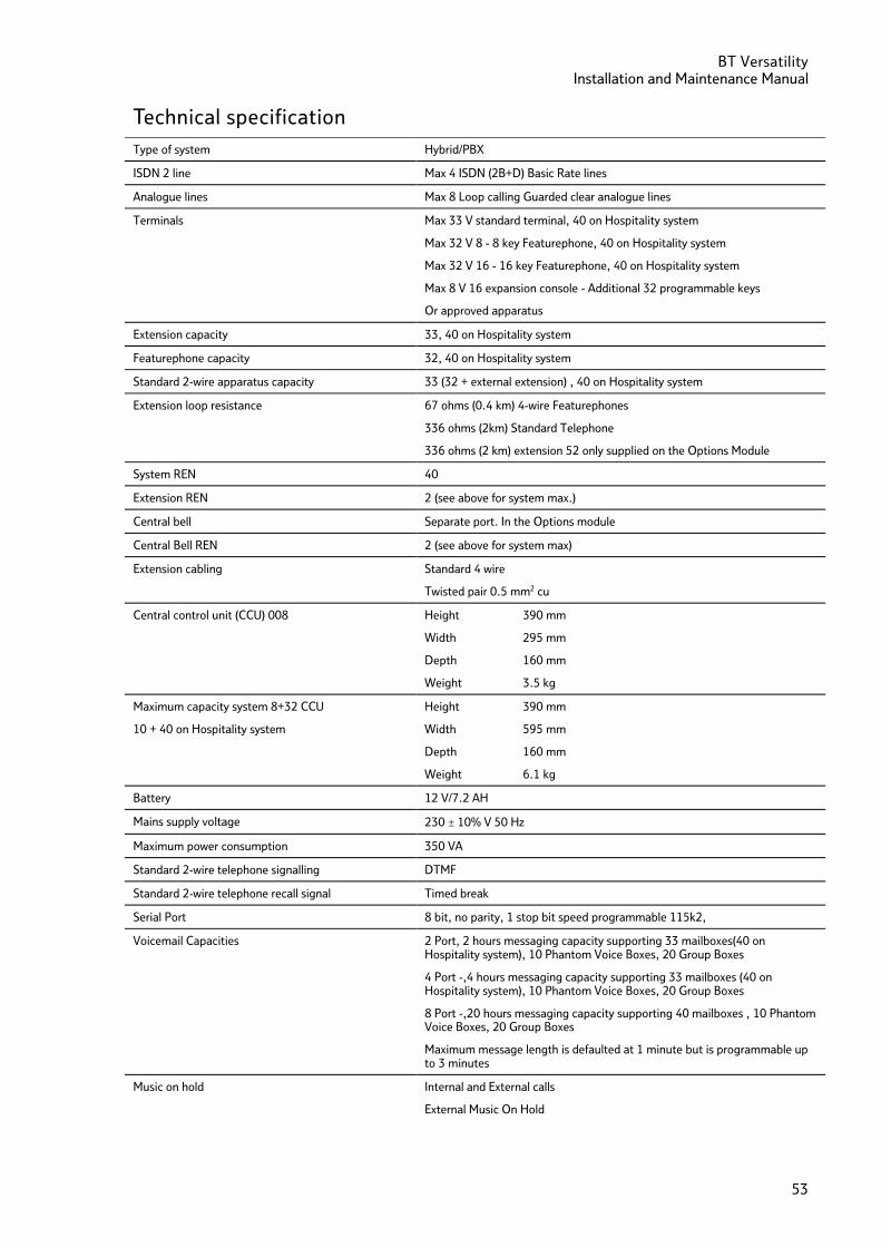
53
Technical specification Type of system Hybrid/PBX
ISDN 2 line Max 4 ISDN (2B+D) Basic Rate lines
Analogue lines Max 8 Loop calling Guarded clear analogue lines
Terminals Max 33 V standard terminal, 40 on Hospitality system
Max 32 V 8 - 8 key Featurephone, 40 on Hospitality system
Max 32 V 16 - 16 key Featurephone, 40 on Hospitality system
Max 8 V 16 expansion console - Additional 32 programmable keys
Or approved apparatus
Extension capacity 33, 40 on Hospitality system
Featurephone capacity 32, 40 on Hospitality system
Standard 2-wire apparatus capacity 33 (32 + external extension) , 40 on Hospitality system
Extension loop resistance 67 ohms (0.4 km) 4-wire Featurephones
336 ohms (2km) Standard Telephone
336 ohms (2 km) extension 52 only supplied on the Options Module
System REN 40
Extension REN 2 (see above for system max.)
Central bell Separate port. In the Options module
Central Bell REN 2 (see above for system max)
Extension cabling Standard 4 wire
Twisted pair 0.5 mm2 cu
Central control unit (CCU) 008 Height 390 mm
Width 295 mm
Depth 160 mm
Weight 3.5 kg
Maximum capacity system 8+32 CCU
10 + 40 on Hospitality system
Height 390 mm
Width 595 mm
Depth 160 mm
Weight 6.1 kg
Battery 12 V/7.2 AH
Mains supply voltage 230 ± 10% V 50 Hz
Maximum power consumption 350 VA
Standard 2-wire telephone signalling DTMF
Standard 2-wire telephone recall signal Timed break
Serial Port 8 bit, no parity, 1 stop bit speed programmable 115k2,
Voicemail Capacities 2 Port, 2 hours messaging capacity supporting 33 mailboxes(40 on Hospitality system), 10 Phantom Voice Boxes, 20 Group Boxes
4 Port -,4 hours messaging capacity supporting 33 mailboxes (40 on Hospitality system), 10 Phantom Voice Boxes, 20 Group Boxes
8 Port -,20 hours messaging capacity supporting 40 mailboxes , 10 Phantom Voice Boxes, 20 Group Boxes
Maximum message length is defaulted at 1 minute but is programmable up to 3 minutes
Music on hold Internal and External calls
External Music On Hold
BT Versatility Installation and maintenance Manual
54
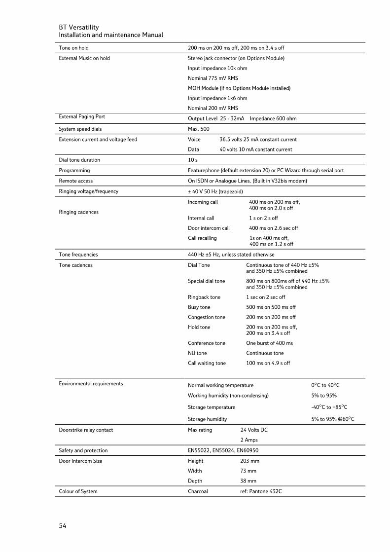
Tone on hold 200 ms on 200 ms off, 200 ms on 3.4 s off
External Music on hold Stereo jack connector (on Options Module)
Input impedance 10k ohm
Nominal 775 mV RMS
MOH Module (if no Options Module installed)
Input impedance 1k6 ohm
Nominal 200 mV RMS
External Paging Port Output Level 25 - 32mA Impedance 600 ohm
System speed dials Max. 500
Extension current and voltage feed Voice 36.5 volts 25 mA constant current
Data 40 volts 10 mA constant current
Dial tone duration 10 s
Programming Featurephone (default extension 20) or PC Wizard through serial port
Remote access On ISDN or Analogue Lines. (Built in V32bis modem)
Ringing voltage/frequency ± 40 V 50 Hz (trapezoid)
Ringing cadences
Incoming call 400 ms on 200 ms off, 400 ms on 2.0 s off
Internal call 1 s on 2 s off
Door intercom call 400 ms on 2.6 sec off
Call recalling 1s on 400 ms off, 400 ms on 1.2 s off
Tone frequencies 440 Hz ±5 Hz, unless stated otherwise
Tone cadences Dial Tone Continuous tone of 440 Hz ±5% and 350 Hz ±5% combined
Special dial tone 800 ms on 800ms off of 440 Hz ±5% and 350 Hz ±5% combined
Ringback tone 1 sec on 2 sec off
Busy tone 500 ms on 500 ms off
Congestion tone 200 ms on 200 ms off
Hold tone 200 ms on 200 ms off, 200 ms on 3.4 s off
Conference tone One burst of 400 ms
NU tone Continuous tone
Call waiting tone 100 ms on 4.9 s off
Environmental requirements Normal working temperature 0°C to 40°C
Working humidity (non-condensing) 5% to 95%
Storage temperature -40°C to +85°C
Storage humidity 5% to 95% @60°C
Doorstrike relay contact Max rating 24 Volts DC
2 Amps
Safety and protection EN55022, EN55024, EN60950
Door Intercom Size Height 203 mm
Width 73 mm
Depth 38 mm
Colour of System Charcoal ref: Pantone 432C
BT Versatility Installation and Maintenance Manual
55
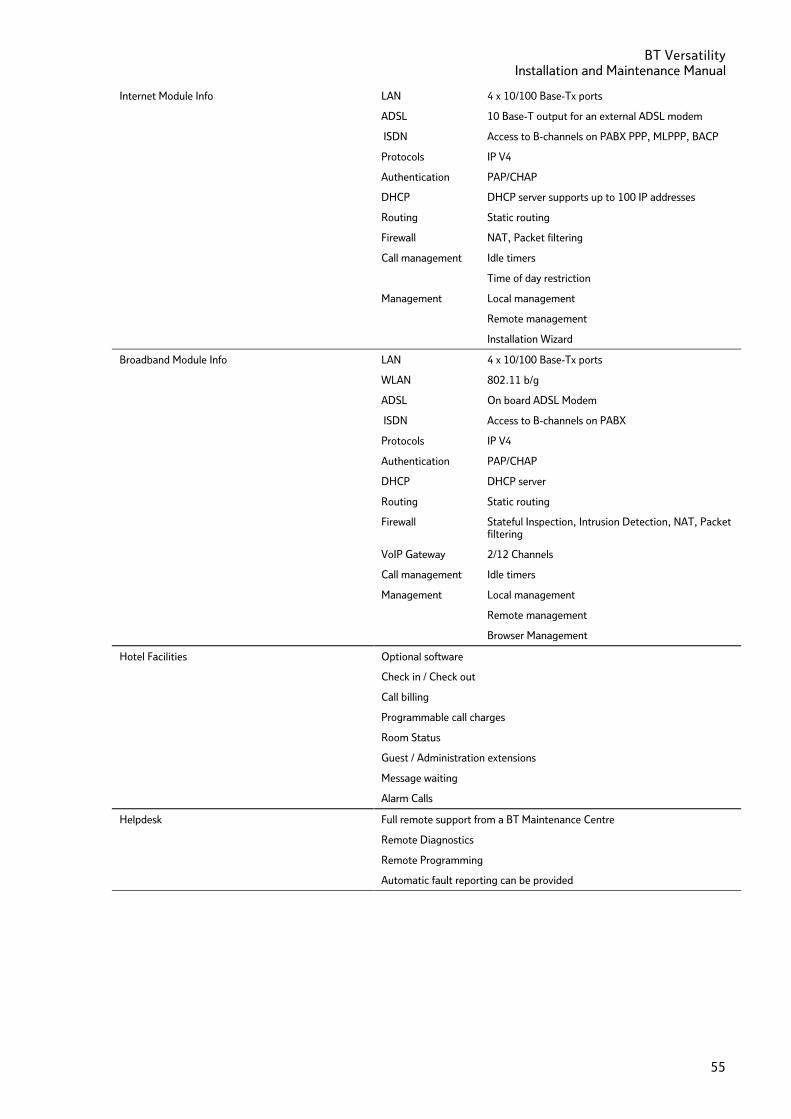
Internet Module Info
LAN 4 x 10/100 Base-Tx ports
ADSL 10 Base-T output for an external ADSL modem
ISDN Access to B-channels on PABX PPP, MLPPP, BACP
Protocols IP V4
Authentication PAP/CHAP
DHCP DHCP server supports up to 100 IP addresses
Routing Static routing
Firewall NAT, Packet filtering
Call management Idle timers
Time of day restriction
Management Local management
Remote management
Installation Wizard
Broadband Module Info LAN 4 x 10/100 Base-Tx ports
WLAN 802.11 b/g
ADSL On board ADSL Modem
ISDN Access to B-channels on PABX
Protocols IP V4
Authentication PAP/CHAP
DHCP DHCP server
Routing Static routing
Firewall Stateful Inspection, Intrusion Detection, NAT, Packet filtering
VoIP Gateway 2/12 Channels
Call management Idle timers
Management Local management
Remote management
Browser Management
Hotel Facilities Optional software
Check in / Check out
Call billing
Programmable call charges
Room Status
Guest / Administration extensions
Message waiting
Alarm Calls
Helpdesk Full remote support from a BT Maintenance Centre
Remote Diagnostics
Remote Programming
Automatic fault reporting can be provided
BT Versatility Installation and maintenance Manual
56
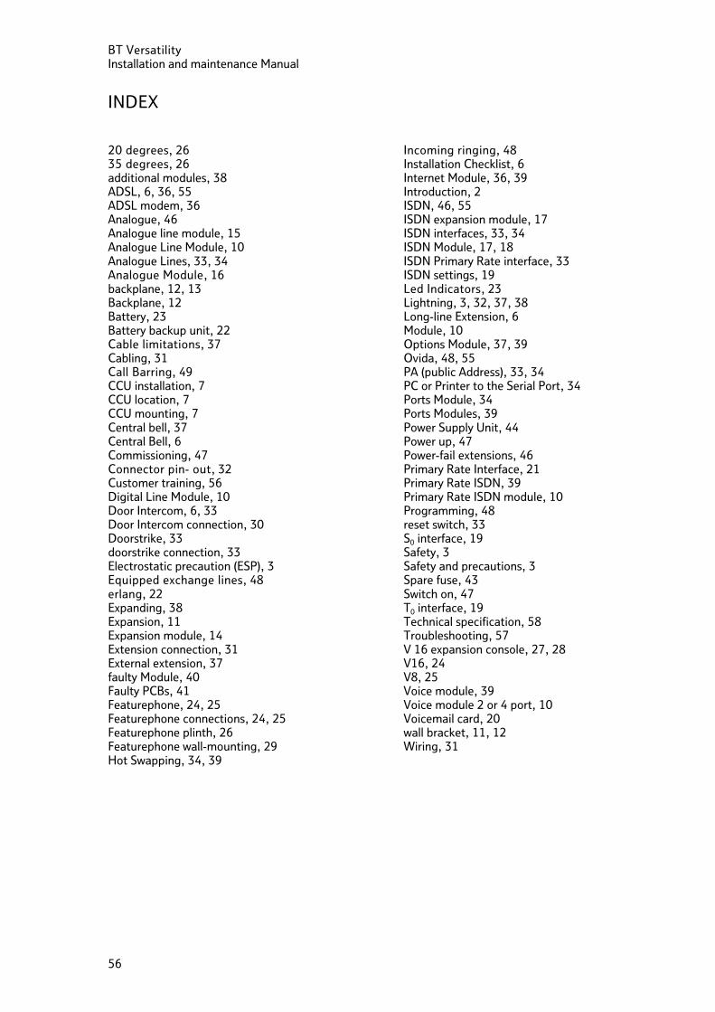
INDEX 20 degrees, 26 35 degrees, 26 additional modules, 38 ADSL, 6, 36, 55 ADSL modem, 36 Analogue, 46 Analogue line module, 15 Analogue Line Module, 10 Analogue Lines, 33, 34 Analogue Module, 16 backplane, 12, 13 Backplane, 12 Battery, 23 Battery backup unit, 22 Cable limitations, 37 Cabling, 31 Call Barring, 49 CCU installation, 7 CCU location, 7 CCU mounting, 7 Central bell, 37 Central Bell, 6 Commissioning, 47 Connector pin- out, 32 Customer training, 56 Digital Line Module, 10 Door Intercom, 6, 33 Door Intercom connection, 30 Doorstrike, 33 doorstrike connection, 33 Electrostatic precaution (ESP), 3 Equipped exchange lines, 48 erlang, 22 Expanding, 38 Expansion, 11 Expansion module, 14 Extension connection, 31 External extension, 37 faulty Module, 40 Faulty PCBs, 41 Featurephone, 24, 25 Featurephone connections, 24, 25 Featurephone plinth, 26 Featurephone wall-mounting, 29 Hot Swapping, 34, 39
Incoming ringing, 48 Installation Checklist, 6 Internet Module, 36, 39 Introduction, 2 ISDN, 46, 55 ISDN expansion module, 17 ISDN interfaces, 33, 34 ISDN Module, 17, 18 ISDN Primary Rate interface, 33 ISDN settings, 19 Led Indicators, 23 Lightning, 3, 32, 37, 38 Long-line Extension, 6 Module, 10 Options Module, 37, 39 Ovida, 48, 55 PA (public Address), 33, 34 PC or Printer to the Serial Port, 34 Ports Module, 34 Ports Modules, 39 Power Supply Unit, 44 Power up, 47 Power-fail extensions, 46 Primary Rate Interface, 21 Primary Rate ISDN, 39 Primary Rate ISDN module, 10 Programming, 48 reset switch, 33 S0 interface, 19 Safety, 3 Safety and precautions, 3 Spare fuse, 43 Switch on, 47 T0 interface, 19 Technical specification, 58 Troubleshooting, 57 V 16 expansion console, 27, 28 V16, 24 V8, 25 Voice module, 39 Voice module 2 or 4 port, 10 Voicemail card, 20 wall bracket, 11, 12 Wiring, 31

Offices Worldwide The telecommunications services described in this publication are subject to availability and may be modified from time to time. Services and equipment are provided subject to British Telecommunications plc’s respective standard conditions of contract. Nothing in this publication forms any part of any contract.
© British Telecommunications plc 2002.
Registered Office: 81 Newgate Street, London EC1A 7AJ. Registered in England No: 1800000. Produced by BT Business Information Systems Marketing Cover designed by H&P Graphics Limited (9966).
Printed in Ireland
Part No. 2734.31000-5
Printed on paper which meets international environmental standards
The CE Marking on this equipment indicates Compliance with the following
This device conforms to Directive 1999/5/EC on Radio Equipment and Telecommunications Terminal Equipment as adopted by the European Parliament And Of The Council