Embed Size (px)
Citation preview
66832-UIM-D-1205
EFFICIENCYRATINGCERTIFIED
ISO 9001Certified Quality
Management System
HIGH EFFICIENCYCLAM TUBE HEAT EXCHANGER SERIESMODELS: G8C/GF8(Single Stage Multi-Position)50 - 150 MBH INPUT(14.65 - 44.00 KW) INPUT
INSTALLATION MANUAL
SECTION I: SAFETYThis is a safety alert symbol. When you see this symbol onlabels or in manuals, be alert to the potential for personalinjury.
Understand and pay particular attention to the signal words DANGER,WARNING, or CAUTION.
DANGER indicates an imminently hazardous situation, which, if notavoided, will result in death or serious injury.
WARNING indicates a potentially hazardous situation, which, if notavoided, could result in death or serious injury.
CAUTION indicates a potentially hazardous situation, which, if notavoided may result in minor or moderate injury. It is also used toalert against unsafe practices and hazards involving only property dam-age.
Improper installation may create a condition where the operation ofthe product could cause personal injury or property damage.Improper installation, adjustment, alteration, service or mainte-nance can cause injury or property damage. Refer to this manualfor assistance or for additional information, consult a qualified con-tractor, installer or service agency.
This product must be installed in strict compliance with the installa-tion instructions and any applicable local, state, and national codesincluding, but not limited to building, electrical, and mechanicalcodes.
TABLE OF CONTENTSSAFETY . . . . . . . . . . . . . . . . . . . . . . . . . . . . . . . . . . . . . . . . . . . . . . . . 1DUCTWORK . . . . . . . . . . . . . . . . . . . . . . . . . . . . . . . . . . . . . . . . . . . . 4FILTERS . . . . . . . . . . . . . . . . . . . . . . . . . . . . . . . . . . . . . . . . . . . . . . . 9GAS PIPING . . . . . . . . . . . . . . . . . . . . . . . . . . . . . . . . . . . . . . . . . . . 11ELECTRICAL POWER . . . . . . . . . . . . . . . . . . . . . . . . . . . . . . . . . . . 13
ACCESSORY CONNECTIONS . . . . . . . . . . . . . . . . . . . . . . . . . . . . .14TWINNING AND STAGING . . . . . . . . . . . . . . . . . . . . . . . . . . . . . . . .14VENT/COMBUSTION AIR SYSTEM . . . . . . . . . . . . . . . . . . . . . . . . .16SAFETY CONTROLS . . . . . . . . . . . . . . . . . . . . . . . . . . . . . . . . . . . .22START-UP AND ADJUSTMENTS . . . . . . . . . . . . . . . . . . . . . . . . . . .22
LIST OF FIGURESUpflow/Horizontal Configuration . . . . . . . . . . . . . . . . . . . . . . . . . . . . . . 5Downflow/Horizontal Configuration . . . . . . . . . . . . . . . . . . . . . . . . . . . 5Vent Blower . . . . . . . . . . . . . . . . . . . . . . . . . . . . . . . . . . . . . . . . . . . . . 5Top Cap . . . . . . . . . . . . . . . . . . . . . . . . . . . . . . . . . . . . . . . . . . . . . . . . 6Dimensions . . . . . . . . . . . . . . . . . . . . . . . . . . . . . . . . . . . . . . . . . . . . . 7Combustible Floor Base Accessory . . . . . . . . . . . . . . . . . . . . . . . . . . . 8Typical Attic Installation . . . . . . . . . . . . . . . . . . . . . . . . . . . . . . . . . . . . 9Typical Suspended Furnace / Crawl Space Installation . . . . . . . . . . . . 9Side Return Cutout Markings . . . . . . . . . . . . . . . . . . . . . . . . . . . . . . . 10Horizontal Mount and Filter . . . . . . . . . . . . . . . . . . . . . . . . . . . . . . . . 10Downflow Filter . . . . . . . . . . . . . . . . . . . . . . . . . . . . . . . . . . . . . . . . . . 10Return Filter Grill and Return Duct Installation . . . . . . . . . . . . . . . . . . 11Gas Valve . . . . . . . . . . . . . . . . . . . . . . . . . . . . . . . . . . . . . . . . . . . . . . 11Upflow Configuration (50-125 MBH Model Only) . . . . . . . . . . . . . . . . 12Downflow Configuration (50-125 MBH Model Only) . . . . . . . . . . . . . 12Upflow/Horizontal Configuration (150 MBH Model Only) . . . . . . . . . . 12Gas Piping . . . . . . . . . . . . . . . . . . . . . . . . . . . . . . . . . . . . . . . . . . . . . 12Electrical Wiring - Upflow Position . . . . . . . . . . . . . . . . . . . . . . . . . . . 14Line Wiring Connections . . . . . . . . . . . . . . . . . . . . . . . . . . . . . . . . . . 14Two-Stage Heating and Cooling Thermostat Connections . . . . . . . . 14
Accessory Connections . . . . . . . . . . . . . . . . . . . . . . . . . . . . . . . . . . .14Typical Twinned Furnace Application . . . . . . . . . . . . . . . . . . . . . . . . .15Single Stage Twinning Wiring Diagram . . . . . . . . . . . . . . . . . . . . . . .15Two-Stage Twinning Wiring Diagram . . . . . . . . . . . . . . . . . . . . . . . . .16Vent Termination . . . . . . . . . . . . . . . . . . . . . . . . . . . . . . . . . . . . . . . .16Vent Termination . . . . . . . . . . . . . . . . . . . . . . . . . . . . . . . . . . . . . . . .16Alternate Air Intake, Air Outlet and Chimney Connections . . . . . . . . .17Air Inlet, Outlet and Chimney Connections . . . . . . . . . . . . . . . . . . . . .17Typical Sidewall Vent Application . . . . . . . . . . . . . . . . . . . . . . . . . . . .18Typical Sidewall Vent and Termination Configuration . . . . . . . . . . . .18Typical Chimney Connections . . . . . . . . . . . . . . . . . . . . . . . . . . . . . .18Horizontal Air Inlet, Outlet and Chimney Connections . . . . . . . . . . . .18Home Layout . . . . . . . . . . . . . . . . . . . . . . . . . . . . . . . . . . . . . . . . . . .19Combustion Airflow Path Through The Furnace Casing to the Burner Box . . . . . . . . . . . . . . . . . . . . . . . . . . . . . . . . . .20Outside and Ambient Combustion Air . . . . . . . . . . . . . . . . . . . . . . . . .21Pressure Switch Tubing Routing . . . . . . . . . . . . . . . . . . . . . . . . . . . .22Gas Valve . . . . . . . . . . . . . . . . . . . . . . . . . . . . . . . . . . . . . . . . . . . . . .25Reading Gas Pressure . . . . . . . . . . . . . . . . . . . . . . . . . . . . . . . . . . . .25Typical Heat/Cool Speed Tap Connections . . . . . . . . . . . . . . . . . . . .26Wiring Diagram . . . . . . . . . . . . . . . . . . . . . . . . . . . . . . . . . . . . . . . . . .28
LIST OF TABLESUnit Clearances to Combustibles . . . . . . . . . . . . . . . . . . . . . . . . . . . . . 4Minimum Duct Sizing For Proper Airflow . . . . . . . . . . . . . . . . . . . . . . . 6External Static Pressure Range . . . . . . . . . . . . . . . . . . . . . . . . . . . . . . 6Cabinet and Duct Dimensions . . . . . . . . . . . . . . . . . . . . . . . . . . . . . . . 7Filter Sizes - Upflow . . . . . . . . . . . . . . . . . . . . . . . . . . . . . . . . . . . . . . 10Inlet Gas Pressure Range . . . . . . . . . . . . . . . . . . . . . . . . . . . . . . . . . 12High Altitude Conversion . . . . . . . . . . . . . . . . . . . . . . . . . . . . . . . . . . 13Ratings & Physical / Electrical Data - Upflow Models . . . . . . . . . . . . 13Roof Pitch . . . . . . . . . . . . . . . . . . . . . . . . . . . . . . . . . . . . . . . . . . . . . . 16
Horizontal Sidewall Venting Clearances . . . . . . . . . . . . . . . . . . . . . . .18Estimated Free Area . . . . . . . . . . . . . . . . . . . . . . . . . . . . . . . . . . . . . .20Free Area . . . . . . . . . . . . . . . . . . . . . . . . . . . . . . . . . . . . . . . . . . . . . .20Unconfined Space Minimum Area in Square Feet . . . . . . . . . . . . . . .20Field Installed Accessories - Non Electrical . . . . . . . . . . . . . . . . . . . .23Inlet Gas Pressure Range . . . . . . . . . . . . . . . . . . . . . . . . . . . . . . . . .25Nominal Manifold Pressure . . . . . . . . . . . . . . . . . . . . . . . . . . . . . . . . .25Filter Performance - Pressure Drop Inches W.C. and (kPa) . . . . . . . .26Blower Performance - CFM . . . . . . . . . . . . . . . . . . . . . . . . . . . . . . . .27
66832-UIM-D-1205
2 Unitary Products Group
SPECIFIC SAFETY RULES AND PRECAUTIONS1. Only Natural gas or Propane (LP) gas are approved for use with
this furnace. Refer to the furnace rating plate or Section IV ofthese instructions.
2. Install this furnace only in a location and position as specified inSECTION I of these instructions.
3. A gas-fired furnace for installation in a residential garage must beinstalled as specified in SECTION I of these instructions.
4. Provide adequate combustion and ventilation air to the furnacespace as specified in SECTION VII of these instructions.
5. Combustion products must be discharged outdoors. Connect thisfurnace to an approved vent system only, as specified in SEC-TION VII of these instructions.
6. Test for gas leaks as specified in SECTION XI of these instruc-tions.
7. Always install the furnace to operate within the furnace’s intendedtemperature rise range. Only connect the furnace to a duct systemwhich has an external static pressure within the allowable range,as specified on the furnace rating plate.
8. When a furnace is installed so that supply ducts carry air circulatedby the furnace to areas outside the space containing the furnace,the return air shall also be handled by duct(s) sealed to the fur-nace casing and terminating outside the space containing the fur-nace.
9. It is permitted to be use the furnace for heating of buildings orstructures under construction. Installation must comply with allmanufacturer’s installation instructions including:• Proper vent installation;• Furnace operating under thermostatic control;• Return air duct sealed to the furnace;• Air filters in place;• Set furnace input rate and temperature rise per rating plate
marking;• Means for providing outdoor air required for combustion;• Return air temperature maintained between 55ºF (13ºC) and
80ºF (27ºC);• The air filter must be replaced upon substantial completion of
the construction process;• Clean furnace, duct work and components upon substantial
completion of the construction process, and verify furnace-operating conditions including ignition, input rate, temperaturerise and venting, according to the manufacturer’s instructions.
The following requirements to be met:a. Clean, outside combustion air is provided to the furnace to
minimize the impact of corrosive adhesives, sealants, andother construction materials. Drywall dust is a major concernduring construction, which can be pulled into the combustionair path, leading to plugged gas valves, burners, and inducerassemblies.
b. Filter must be installed in the furnace as specified in theinstallation instructions, and must be replaced or thoroughlycleaned prior to occupancy of the home. Again, drywall dustis the key issue, as that dust can be pulled into the circulatingblower motor, plugging the motor vents, coating the rotorsand stators, etc. which can lead to a potential fire hazard.
c. The temperature of the return air to the furnace must not beless than 55 degrees F (13 deg C), with no evening setbackor furnace shutdown, to prevent condensation in the primaryheat exchangers.
d. The air temperature rise must be within the stated rise rangeas indicated on the furnace rating plate, and the firing inputrate must be set to the unit nameplate value.
e. The external static pressure of the air distribution systemductwork must at set for heating operation to be at least 0.10to 0.20 inches water column, based on the input rate of thefurnace, with the lower value for input rates less than 55,000btu/hr and the upper value for units with input rates above100,000 btu/hr.
f. A return air duct must be used, sealed to the furnace cabinet,and terminated outside the space where the furnace isinstalled. This prevents any recirculation of supply air, whichcan generate a negative pressure condition at the furnace fornon-direct vent furnaces, leading to possible flame rollout orcombustion problems.
g. The furnace and ductwork should be thoroughly and com-pletely cleaned prior to occupancy of the dwelling to insurethe proper operation of the furnace and to avoid potentialhealth concerns.
10. When installed in a Non-HUD-Approved Modular Home or buildingconstructed on-site, combustion air shall not be supplied fromoccupied spaces.
11. The size of the unit should be based on an acceptable heat losscalculation for the structure. ACCA, Manual J or other approvedmethods may be used.
SAFETY REQUIREMENTS• This furnace should be installed in accordance with all national
and local building/safety codes and requirements, local plumbingor wastewater codes, and other applicable codes. In the absenceof local codes, install in accordance with the National Fuel GasCode ANSI Z223.1/NFPA 54, National Fuel Gas Code, and/orCAN/CGA B149.1 Natural Gas and Propane Installation Code(latest editions). Furnaces have been certified to the latest editionof standard ANSI Z21-47 • CSA 2.3.
• Refer to the unit rating plate for the furnace model number, andthen see the dimensions page of this instruction for return air ple-num dimensions in Figure 5. The plenum must be installedaccording to the instructions.
• Provide clearances from combustible materials as listed underClearances to Combustibles.
• Provide clearances for servicing ensuring that service access isallowed for both the burners and blower.
• These models ARE NOT CSA listed or approved for installationinto a HUD Approved Modular Home or a Manufactured(Mobile) Home.
• This furnace is not approved for installation in trailers or recre-ational vehicles.
• Failure to carefully read and follow all instructions in thismanual can result in furnace malfunction, death, personalinjury and/or property damage.
• Furnaces for installation on combustible flooring shall not beinstalled directly on carpeting, tile or other combustible materialother than wood flooring.
• Check the rating plate and power supply to be sure that the elec-trical characteristics match. All models use nominal 115 VAC, 1Phase, 60-Hertz power supply. DO NOT CONNECT THIS APPLI-ANCE TO A 50 HZ POWER SUPPLY OR A VOLTAGE ABOVE130 VOLTS.
FIRE OR EXPLOSION HAZARDFailure to follow the safety warnings exactly could result in seriousinjury, death or property damage.Never test for gas leaks with an open flame. Use a commerciallyavailable soap solution made specifically for detection of leaks tocheck all connections. A fire or explosion may result causing prop-erty damage, personal injury or loss of life.
66832-UIM-D-1205
Unitary Products Group 3
• Furnace shall be installed so the electrical components are pro-tected from water.
• Installing and servicing heating equipment can be hazardous dueto the electrical components and the gas fired components. Onlytrained and qualified personnel should install, repair, or servicegas heating equipment. Untrained service personnel can performbasic maintenance functions such as cleaning and replacing theair filters. When working on heating equipment, observe precau-tions in the manuals and on the labels attached to the unit andother safety precautions that may apply.
• These instructions cover minimum requirements and conform toexisting national standards and safety codes. In some instancesthese instructions exceed certain local codes and ordinances,especially those who have not kept up with changing residentialand non-HUD modular home construction practices. Theseinstructions are required as a minimum for a safe installation.
COMBUSTION AIR QUALITY (LIST OF CONTAMINANTS)The furnace will require OUTDOOR AIR for combustion when the fur-nace is located in any of the following environments.
• Restricted Environments • Commercial buildings • Buildings with indoor pools • Furnaces installed in laundry rooms • Furnaces installed in hobby or craft rooms • Furnaces installed near chemical storage areas • Chemical Exposure
The furnace will require OUTDOOR AIR for combustion when the fur-nace is located in an area where the furnace is being exposed to the fol-lowing substances and / or chemicals.
• Permanent wave solutions • Chlorinated waxes and cleaners • Chlorine based swimming pool chemicals • Water softening chemicals • De-icing salts or chemicals • Carbon tetrachloride • Halogen type refrigerants • Cleaning solvents (such as perchloroethylene) • Printing inks, paint removers, varnishes, etc. • Hydrochloric acid • Cements and glues • Antistatic fabric softeners for clothes dryers • Masonry acid washing materials
If outdoor air is used for combustion, the combustion air intake duct sys-tem termination must be located external to the building and in an areawhere there will be no exposure to the substances listed above.
INSPECTIONAs soon as a unit is received, it should be inspected for possible dam-age during transit. If damage is evident, the extent of the damageshould be noted on the carrier’s freight bill. A separate request forinspection by the carrier’s agent should be made in writing. Also, beforeinstallation the unit should be checked for screws or bolts, which mayhave loosened in transit, and any shipping or spacer brackets whichneed to be removed.
FURNACE LOCATION AND CLEARANCESThe furnace shall be located using the following guidelines:1. Where a minimum amount of air intake/vent piping and elbows will
be required.2. As centralized with the air distribution as possible.3. Where adequate combustion air will be available (particularly
when the appliance is not using outdoor combustion air).4. Where it will not interfere with proper air circulation in the confined
space.5. Where the outdoor vent terminal will not be blocked or restricted.
Refer to “VENT CLEARANCES” located in SECTION VII of theseinstructions. These minimum clearances must be maintained inthe installation.
6. Where the unit will be installed in a level position with no morethan 1/4” (0.64 cm) slope side-to-side and front-to-back to provideproper condensate drainage.
Installation in freezing temperatures:1. Furnace shall be installed in an area where ventilation facilities
provide for safe limits of ambient temperature under normal oper-ating conditions. Ambient temperatures falling below 32° F (0° C)may result in the flue temperature falling below 260° F (127° C) atany point in the flue pipe between the furnace and the chimney ora B-Vent. The flue products will condense in the vent pipe if theflue temperature falls below 260° F (127° C) causing the vent pipeto deteriorate rapidly.
2. Do not allow return air temperature to be below 55º F (13° C) forextended periods. To do so may cause condensation to occur inthe main heat exchanger, leading to premature heat exchangerfailure.
3. If this furnace is installed in an unconditioned space and anextended power failure occurs, there will be potential damage tothe internal components. Following a power failure situation, donot operate the unit until inspection and repairs are performed.
Clearances for access:Ample clearances should be provided to permit easy access to the unit.The following minimum clearances are recommended:1. Twenty-four (24) inches (61 cm) between the front of the furnace
and an adjacent wall or another appliance, when access isrequired for servicing and cleaning.
2. Eighteen (18) inches (46 cm) at the side where access is requiredfor passage to the front when servicing or for inspection orreplacement of flue/vent connections.
In all cases, accessibility clearances shall take precedence over clear-ances for combustible materials where accessibility clearances aregreater.
The furnace area must not be used as a broom closet or for anyother storage purposes, as a fire hazard may be created. Neverstore items such as the following on, near or in contact with the fur-nace.
1. Spray or aerosol cans, rags, brooms, dust mops, vacuumcleaners or other cleaning tools.
2. Soap powders, bleaches, waxes or other cleaning com-pounds; plastic items or containers; gasoline, kerosene, ciga-rette lighter fluid, dry cleaning fluids or other volatile fluid.
3. Paint thinners and other painting compounds.4. Paper bags, boxes or other paper products
Never operate the furnace with the blower door removed. Todo so could result in serious personal injury and/or equipmentdamage.
Improper installation in an ambient below 32ºF (0.0° C) could createa hazard, resulting in damage, injury or death.
66832-UIM-D-1205
4 Unitary Products Group
Installation in a residential garage:A gas-fired furnace for installation in a residential garage must beinstalled so the burner(s) and the ignition source are located not lessthan (18) inches (46 cm) above the floor, and the furnace must belocated or protected to avoid physical damage by vehicles.
SECTION II: DUCTWORKDUCTWORK GENERAL INFORMATIONThe duct system’s design and installation must:1. Handle an air volume appropriate for the served space and within
the operating parameters of the furnace specifications.2. Be installed in accordance with standards of NFPA (National Fire
Protection Association) as outlined in NFPA pamphlets 90A and90B (latest editions) or applicable national, provincial, or state, andlocal fire and safety codes or in Canada, refer to the Natural Gasand Propane Installation Code B149.1-00.
3. Create a closed duct system. For residential and Non-HUD Modu-lar Home installations, when a furnace is installed so that the sup-ply ducts carry air circulated by the furnace to areas outside thespace containing the furnace, the return air shall also be handledby a duct(s) sealed to the furnace casing and terminating outsidethe space containing the furnace.
4. Complete a path for heated or cooled air to circulate through theair conditioning and heating equipment and to and from the condi-tioned space.
When the furnace is used in conjunction with a cooling coil, the coilmust be installed parallel with, or in the supply air side of the furnace toavoid condensation in the primary heat exchanger. When a parallel flowarrangement is used, dampers or other means used to control airflowmust be adequate to prevent chilled air from entering the furnace. Ifmanually operated, the damper must be equipped with means to pre-vent the furnace or the air conditioner from operating unless the damperis in full heat or cool position.
INSTALLATION POSITION (50-125 MBH Models)This furnace may be installed in an upflow, downflow or horizontal posi-tion. Depending on the configuration shipped from the factory, it may benecessary to convert the furnace from downflow to upflow or fromupflow to downflow configuration. Use conversion instructions in thisdocument.
INSTALLATION POSITION (150 MBH Models)This furnace may be installed in an upflow or horizontal position. Noconversion is necessary. This furnace is not approved for downflowapplication.
CONVERSION INFORMATION (50-125 MBH Models)This furnace may be shipped in either the upflow or the downflow con-figuration. To convert from upflow to downflow or vice-versa it is neces-sary only to exchange the top and bottom casing caps and to rotate thevent blower 180 degrees. Use the step by step instructions to performthe conversion.
Downflow furnaces for installation on combustible flooring onlywhen installed on the accessory combustible floor base on woodflooring only and shall not be installed directly on carpeting, tile orother combustible material.Check the rating plate and power supply to be sure that the electri-cal characteristics match. All models use nominal 115 VAC, 1Phase 60Hz power supply.Furnace shall be installed so the electrical components are pro-tected from water.
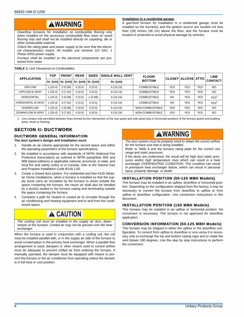
TABLE 1: Unit Clearances to Combustibles
APPLICATIONTOP FRONT REAR SIDES SINGLE WALL VENT FLOOR/
BOTTOM CLOSET ALCOVE ATTIC LINE CONTACTIn. (cm) In. (cm) In. (cm) In. (cm) In. (cm)
UPFLOW 1 (25.4) 2 (5.08) 0 (0.0) 0 (0.0) 6 (15.24) COMBUSTIBLE YES YES YES NO
UPFLOW B-VENT 1 (25.4) 3 (7.62) 0 (0.0) 0 (0.0) 6 (15.24) COMBUSTIBLE YES YES YES NO
HORIZONTAL 1 (25.4) 2 (5.08) 0 (0.0) 1 (5.08) 6 (15.24) COMBUSTIBLE NO YES YES YES1
1. Line contact only permitted between lines formed by the intersection of the rear panel and side panel (top in horizontal position) of the furnace jacket and building joists, studs or framing.
HORIZONTAL B-VENT 1 (25.4) 3 (7.62) 0 (0.0) 0 (0.0) 6 (15.24) COMBUSTIBLE NO YES YES YES1
DOWNFLOW 1 (25.4) 2 (5.08) 0 (0.0) 0 (0.0) 6 (15.24) NON-COMBUSTIBLE YES YES YES NO
DOWNFLOW B-VENT 1 (25.4) 3 (7.62) 0 (0.0) 0 (0.0) 6 (15.24) NON-COMBUSTIBLE YES YES YES NO
The cooling coil must be installed in the supply air duct, down-stream of the furnace. Cooled air may not be passed over the heatexchanger.
The duct system must be properly sized to obtain the correct airflowfor the furnace size that is being installed.Refer to Table 8 and the furnace rating plate for the correct riserange and static pressuresIf the ducts are undersized, the result will be high duct static pres-sures and/or high temperature rises which can result in a heatexchanger OVERHEATING CONDITION. This condition can resultin premature heat exchanger failure, which can result in personalinjury, property damage, or death.
66832-UIM-D-1205
Unitary Products Group 5
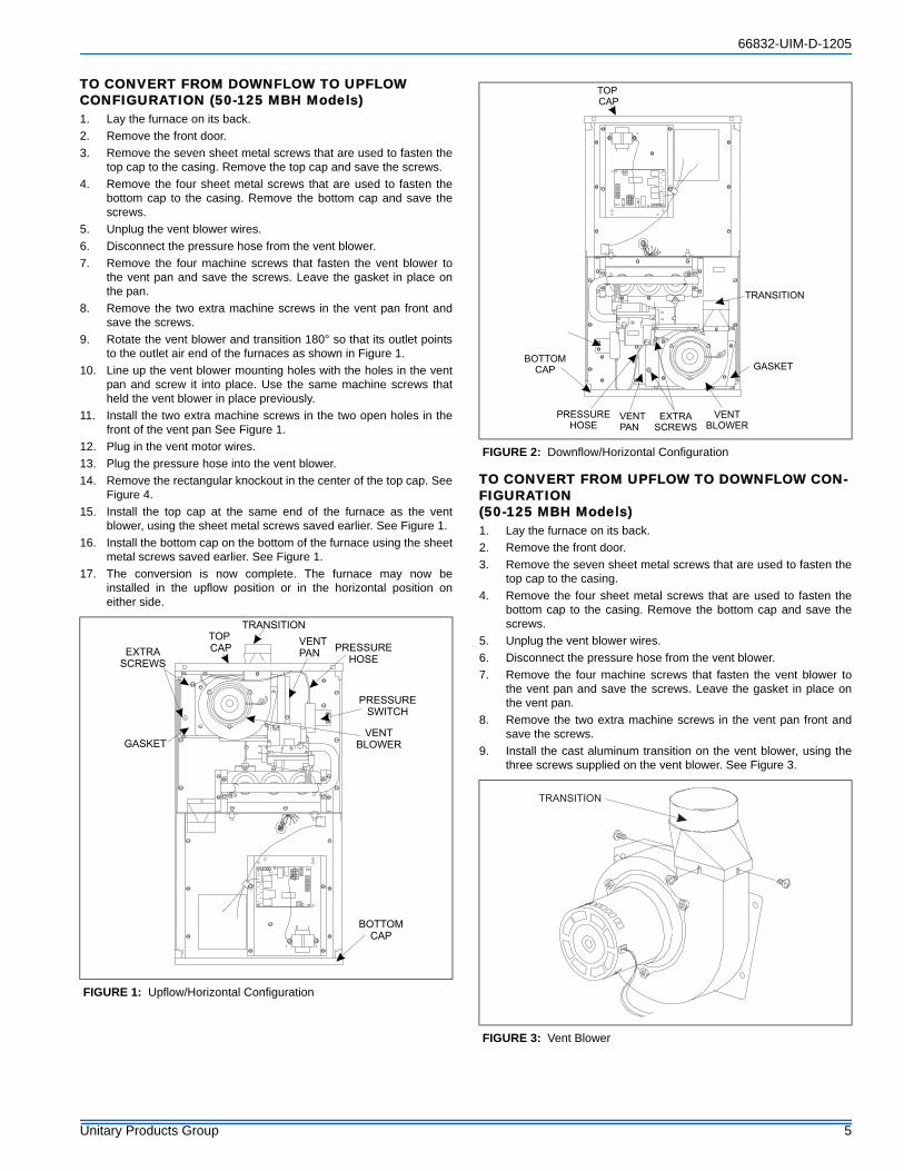
TO CONVERT FROM DOWNFLOW TO UPFLOW CONFIGURATION (50-125 MBH Models)1. Lay the furnace on its back.2. Remove the front door.3. Remove the seven sheet metal screws that are used to fasten the
top cap to the casing. Remove the top cap and save the screws.4. Remove the four sheet metal screws that are used to fasten the
bottom cap to the casing. Remove the bottom cap and save thescrews.
5. Unplug the vent blower wires.6. Disconnect the pressure hose from the vent blower.7. Remove the four machine screws that fasten the vent blower to
the vent pan and save the screws. Leave the gasket in place onthe pan.
8. Remove the two extra machine screws in the vent pan front andsave the screws.
9. Rotate the vent blower and transition 180° so that its outlet pointsto the outlet air end of the furnaces as shown in Figure 1.
10. Line up the vent blower mounting holes with the holes in the ventpan and screw it into place. Use the same machine screws thatheld the vent blower in place previously.
11. Install the two extra machine screws in the two open holes in thefront of the vent pan See Figure 1.
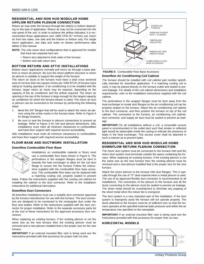
12. Plug in the vent motor wires.13. Plug the pressure hose into the vent blower.14. Remove the rectangular knockout in the center of the top cap. See
Figure 4.15. Install the top cap at the same end of the furnace as the vent
blower, using the sheet metal screws saved earlier. See Figure 1.16. Install the bottom cap on the bottom of the furnace using the sheet
metal screws saved earlier. See Figure 1.17. The conversion is now complete. The furnace may now be
installed in the upflow position or in the horizontal position oneither side.
TO CONVERT FROM UPFLOW TO DOWNFLOW CON-FIGURATION (50-125 MBH Models)1. Lay the furnace on its back.2. Remove the front door.3. Remove the seven sheet metal screws that are used to fasten the
top cap to the casing. 4. Remove the four sheet metal screws that are used to fasten the
bottom cap to the casing. Remove the bottom cap and save thescrews.
5. Unplug the vent blower wires.6. Disconnect the pressure hose from the vent blower.7. Remove the four machine screws that fasten the vent blower to
the vent pan and save the screws. Leave the gasket in place onthe vent pan.
8. Remove the two extra machine screws in the vent pan front andsave the screws.
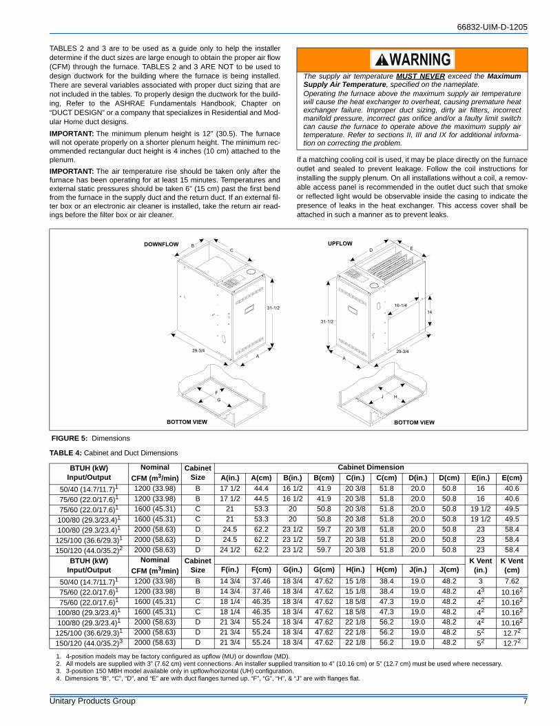
9. Install the cast aluminum transition on the vent blower, using thethree screws supplied on the vent blower. See Figure 3.
FIGURE 1: Upflow/Horizontal Configuration
GASKET
EXTRASCREWS
TOPCAP
TRANSITION
PRESSUREHOSE
PRESSURESWITCH
VENTBLOWER
BOTTOMCAP
VENTPAN
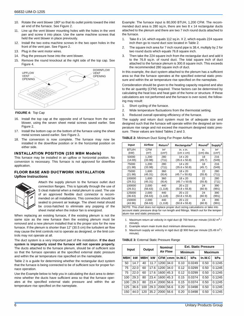
FIGURE 2: Downflow/Horizontal Configuration
FIGURE 3: Vent Blower
GASKET
EXTRASCREWS
TOPCAP
TRANSITION
PRESSUREHOSE
VENTBLOWER
VENTPAN
BOTTOMCAP
TRANSITION
66832-UIM-D-1205
6 Unitary Products Group
10. Rotate the vent blower 180º so that its outlet points toward the inletair end of the furnace. See Figure 2.
11. Line up the vent blower mounting holes with the holes in the ventpan and screw it into place. Use the same machine screws thatheld the vent blower in place previously.
12. Install the two extra machine screws in the two open holes in thefront of the vent pan. See Figure 2.
13. Plug in the vent motor wires.14. Plug the pressure hose into the vent blower.15. Remove the round knockout at the right side of the top cap. See
Figure 4.
16. Install the top cap at the opposite end of furnace from the ventblower, using the seven sheet metal screws saved earlier. SeeFigure 2.
17. Install the bottom cap on the bottom of the furnace using the sheetmetal screws saved earlier. See Figure 2.
18. The conversion is now complete. The furnace may now beinstalled in the downflow position or in the horizontal position oneither side.
INSTALLATION POSITION (150 MBH Models)This furnace may be installed in an upflow or horizontal position. Noconversion is necessary. This furnace is not approved for downflowapplication.
FLOOR BASE AND DUCTWORK INSTALLATIONUpflow Instructions
Attach the supply plenum to the furnace outlet ductconnection flanges. This is typically through the use ofS cleat material when a metal plenum is used. The useof an approved flexible duct connector is recom-mended on all installations. This connection should besealed to prevent air leakage. The sheet metal shouldbe cross-hatched to eliminate any popping of thesheet metal when the indoor fan is energized.
When replacing an existing furnace, if the existing plenum is not thesame size as the new furnace then the existing plenum must beremoved and a new plenum installed that is the proper size for the newfurnace. If the plenum is shorter than 12” (30.5 cm) the turbulent air flowmay cause the limit controls not to operate as designed, or the limit con-trols may not operate at all.The duct system is a very important part of the installation. If the ductsystem is improperly sized the furnace will not operate properly.The ducts attached to the furnace plenum, should be of sufficient sizeso that the furnace operates at the specified external static pressureand within the air temperature rise specified on the nameplate.Table 2 is a guide for determining whether the rectangular duct systemthat the furnace is being connected to be of sufficient size for proper fur-nace operation.Use the Example below to help you in calculating the duct area to deter-mine whether the ducts have sufficient area so that the furnace oper-ates at the specified external static pressure and within the airtemperature rise specified on the nameplate.
Example: The furnace input is 80,000 BTUH, 1,200 CFM. The recom-mended duct area is 280 sq.in, there are two 8 x 14 rectangular ductsattached to the plenum and there are two 7 inch round ducts attached tothe furnace.1. Take 8 x 14, which equals 112 sq.in. X 2, which equals 224 square
inch then go to round duct size located in Table 2.2. The square inch area for 7 inch round pipe is 38.4, multiply by 2 for
two round ducts which equals 76.8 square inch.3. Then take the 224 square inch from the rectangular duct and add it
to the 76.8 sq.in. of round duct. The total square inch of ductattached to the furnace plenum is 300.8 square inch. This exceedsthe recommended 280 square inch of duct.
In this example, the duct system attached to the plenum has a sufficientarea so that the furnace operates at the specified external static pres-sure and within the air temperature rise specified on the nameplate.Consideration should be given to the heating capacity required and alsoto the air quantity (CFM) required. These factors can be determined bycalculating the heat loss and heat gain of the home or structure. If thesecalculations are not performed and the furnace is over-sized, the follow-ing may result:1. Short cycling of the furnace.2. Wide temperature fluctuations from the thermostat setting.3. Reduced overall operating efficiency of the furnace.The supply and return duct system must be of adequate size anddesigned such that the furnace will operate within the designed air tem-perature rise range and not exceed the maximum designed static pres-sure. These values are listed Tables 2 and 3.
FIGURE 4: Top Cap
UPFLOWVENTOPENING
DOWNFLOWVENTOPENING
TABLE 2: Minimum Duct Sizing For Proper Airflow
Input Airflow Return1
1. Maximum return air velocity in rigid duct @ 700 feet per minute (19.82 m3 / minute).
Rectangular2
2. Example return main trunk duct minimum dimensions.
Round2 Supply3
3. Maximum supply air velocity in rigid duct @ 900 feet per minute (25.49 m3 / minute).
BTU/H(kW)
CFM(m³)
In²(cm²)
in. x in.(cm x cm)
in. (cm) dia.
In²(cm²)
50000 (14.65)
1,200 (33.98)
280(711)
14 x 20 (35.6 x 50.8)
18 (45.7)
216(549)
75000 (21.98)
1,200 (33.98)
280 (711)
14 x 20 (35.6 x 50.8)
18 (45.7)
216 (549)
75000(21.98)
1,600 (45.31)
360 (914)
18 x 20 (45.7 x 50.8))
22 (55.8)
280 (711)
100000(29.31)
1,600 (45.31)
360 (914)
18 x 20 (45.7 x 50.8)
22 (55.8)
280 (711)
100000 (29.31)
2,000 (56.63)
440 (1,118)
20 x 22 (50.8 x 55.8)
24 (60.9)
390 (991)
125000 (36.63)
2,000 (56.63)
440 (1,118)
20 x 22 (50.8 x 55.8)
24 (60.9)
390 (991)
150000 (43.96)
2,000 (56.63)
440 (1,118)
20 x 22 (50.8 x 55.8)
24 (60.9)
390 (991)
NOTE: This chart does not replace proper duct sizing calculations or take into account static pressure drop for run length and fittings. Watch out for the temper-ature rise and static pressures.
TABLE 3: External Static Pressure Range
Input Output NominalAir Flow
Ext. Static Pressure
Minimum Maximum
MBH kW MBH kW CFM cmm In.W.C kPa In.W.C kPa50 14.7 40 11.7 1200 34.0 0.10 0.0249 0.50 0.124575 22.0 60 17.6 1200 34.0 0.12 0.0299 0.50 0.124575 22.0 60 17.6 1600 45.3 0.12 0.0299 0.50 0.1245
100 29.3 80 23.4 1600 45.3 0.15 0.0374 0.50 0.1245100 29.3 80 23.4 2000 56.6 0.15 0.0374 0.50 0.1245125 36.6 100 29.3 2000 56.6 0.20 0.0498 0.50 0.1245150 44.0 120 35.2 2000 56.6 0.20 0.0498 0.50 0.1245
66832-UIM-D-1205
Unitary Products Group 7
TABLES 2 and 3 are to be used as a guide only to help the installerdetermine if the duct sizes are large enough to obtain the proper air flow(CFM) through the furnace. TABLES 2 and 3 ARE NOT to be used todesign ductwork for the building where the furnace is being installed.There are several variables associated with proper duct sizing that arenot included in the tables. To properly design the ductwork for the build-ing, Refer to the ASHRAE Fundamentals Handbook, Chapter on“DUCT DESIGN” or a company that specializes in Residential and Mod-ular Home duct designs.IMPORTANT: The minimum plenum height is 12" (30.5). The furnacewill not operate properly on a shorter plenum height. The minimum rec-ommended rectangular duct height is 4 inches (10 cm) attached to theplenum.IMPORTANT: The air temperature rise should be taken only after thefurnace has been operating for at least 15 minutes. Temperatures andexternal static pressures should be taken 6" (15 cm) past the first bendfrom the furnace in the supply duct and the return duct. If an external fil-ter box or an electronic air cleaner is installed, take the return air read-ings before the filter box or air cleaner.
I
If a matching cooling coil is used, it may be place directly on the furnaceoutlet and sealed to prevent leakage. Follow the coil instructions forinstalling the supply plenum. On all installations without a coil, a remov-able access panel is recommended in the outlet duct such that smokeor reflected light would be observable inside the casing to indicate thepresence of leaks in the heat exchanger. This access cover shall beattached in such a manner as to prevent leaks.
The supply air temperature MUST NEVER exceed the MaximumSupply Air Temperature, specified on the nameplate.Operating the furnace above the maximum supply air temperaturewill cause the heat exchanger to overheat, causing premature heatexchanger failure. Improper duct sizing, dirty air filters, incorrectmanifold pressure, incorrect gas orifice and/or a faulty limit switchcan cause the furnace to operate above the maximum supply airtemperature. Refer to sections II, III and IX for additional informa-tion on correcting the problem.
FIGURE 5: Dimensions
DOWNFLOW UPFLOW
AA
BED
BOTTOM VIEW
F
G
29-3/4 29-3/4
C
31-1/2
31-1/2
14
BOTTOM VIEW
HJ
16-1/4
TABLE 4: Cabinet and Duct Dimensions
BTUH (kW)Input/Output
NominalCFM (m3/min)
CabinetSize
Cabinet DimensionA(in.) A(cm) B(in.) B(cm) C(in.) C(cm) D(in.) D(cm) E(in.) E(cm)
50/40 (14.7/11.7)1 1200 (33.98) B 17 1/2 44.4 16 1/2 41.9 20 3/8 51.8 20.0 50.8 16 40.675/60 (22.0/17.6)1 1200 (33.98) B 17 1/2 44.5 16 1/2 41.9 20 3/8 51.8 20.0 50.8 16 40.675/60 (22.0/17.6)1 1600 (45.31) C 21 53.3 20 50.8 20 3/8 51.8 20.0 50.8 19 1/2 49.5
100/80 (29.3/23.4)1 1600 (45.31) C 21 53.3 20 50.8 20 3/8 51.8 20.0 50.8 19 1/2 49.5100/80 (29.3/23.4)1 2000 (58.63) D 24.5 62.2 23 1/2 59.7 20 3/8 51.8 20.0 50.8 23 58.4
125/100 (36.6/29.3)1 2000 (58.63) D 24.5 62.2 23 1/2 59.7 20 3/8 51.8 20.0 50.8 23 58.4150/120 (44.0/35.2)2 2000 (58.63) D 24 1/2 62.2 23 1/2 59.7 20 3/8 51.8 20.0 50.8 23 58.4
BTUH (kW)Input/Output
NominalCFM (m3/min)
CabinetSize
K Vent (in.)
K Vent (cm)F(in.) F(cm) G(in.) G(cm) H(in.) H(cm) J(in.) J(cm)
50/40 (14.7/11.7)1 1200 (33.98) B 14 3/4 37.46 18 3/4 47.62 15 1/8 38.4 19.0 48.2 3 7.6275/60 (22.0/17.6)1 1200 (33.98) B 14 3/4 37.46 18 3/4 47.62 15 1/8 38.4 19.0 48.2 43 10.162
75/60 (22.0/17.6)1 1600 (45.31) C 18 1/4 46.35 18 3/4 47.62 18 5/8 47.3 19.0 48.2 42 10.162
100/80 (29.3/23.4)1 1600 (45.31) C 18 1/4 46.35 18 3/4 47.62 18 5/8 47.3 19.0 48.2 42 10.162
100/80 (29.3/23.4)1 2000 (58.63) D 21 3/4 55.24 18 3/4 47.62 22 1/8 56.2 19.0 48.2 42 10.162
125/100 (36.6/29.3)1 2000 (58.63) D 21 3/4 55.24 18 3/4 47.62 22 1/8 56.2 19.0 48.2 52 12.72
150/120 (44.0/35.2)3 2000 (58.63) D 21 3/4 55.24 18 3/4 47.62 22 1/8 56.2 19.0 48.2 52 12.72
1. 4-position models may be factory configured as upflow (MU) or downflow (MD).2. All models are supplied with 3” (7.62 cm) vent connections. An installer supplied transition to 4” (10.16 cm) or 5” (12.7 cm) must be used where necessary.3. 3-position 150 MBH model available only in upflow/horizontal (UH) configuration.4. Dimensions “B”, “C”, “D”, and “E” are with duct flanges turned up. “F”, “G”, “H”, & “J” are with flanges flat.
66832-UIM-D-1205
8 Unitary Products Group
RESIDENTIAL AND NON HUD MODULAR HOME UPFLOW RETURN PLENUM CONNECTIONReturn air may enter the furnace through the side(s) or bottom depend-ing on the type of application. Return air may not be connected into therear panel of the unit. In order to achieve the airflow indicated, it is rec-ommended those applications over 1800 CFM (57 m³/min) use returnair from two sides, one side and the bottom or bottom only. For singlereturn application, see data and notes on blower performance datatables in this manual.NOTE: The only return duct configurations that is approved for models
that have two separate fans are:• Return duct attached to both sides of the furnace.• Bottom and side return duct.
BOTTOM RETURN AND ATTIC INSTALLATIONSBottom return applications normally pull return air through a base plat-form or return air plenum. Be sure the return platform structure or returnair plenum is suitable to support the weight of the furnace.The return air ducts to the furnace must have a total cross sectionalarea of not less than two square inches per 1000 BTUH of furnace inputrating for heating operation. If air conditioning is to be installed with thefurnace, larger return air ducts may be required, depending on thecapacity of the air conditioner and the airflow required. The return airopening in the top of the furnace is large enough for the largest capacityair conditioner for which the furnace blower is rated. The return air ductor plenum can be connected to the furnace by performing the followingsteps:1. Bend the 3/4" flanges that will be used to attach the return air ple-
num using the scribe marks in the furnace base. Refer to Figure 5for flange locations.
2. Be sure to seal the furnace to plenum connections to prevent airleakage. Refer to Figure 5 for unit and plenum dimensions. Atticinstallations must meet all minimum clearances to combustiblesand have floor support with required service accessibility.
Attic installations must meet all minimum clearances to combustiblesand have floor support with required service accessibility.
FLOOR BASE AND DUCTWORK INSTALLATIONDownflow Combustible Floor Base
Installations on combustible material or floors mustuse a combustible floor base shown in Figure 6. Theperforations in the wrapper flanges must be bent intowards the heat exchanger to allow for the coil ductflange to recess into the furnace Follow the instruc-tions supplied with the combustible floor base acces-sory. This combustible floor base can be replaced witha matching cooling coil, properly sealed to prevent
leaks. Follow the instructions supplied with the cooling coil cabinet forinstalling the cabinet to the duct connector. Refer to the installationinstructions for additional information.
Downflow Duct ConnectorsAll downflow installations must use a suitable duct connector approvedby the furnace manufacturer for use with this furnace. The duct connec-tors are designed to be connected to the rectangular duct under thefloor and sealed. Refer to the instructions supplied with the duct con-nector for proper installation. Refer to the separate accessory parts listat the end of these instructions for the approved accessory duct con-nectors.When replacing an existing furnace, if the existing plenum is not thesame size as the new furnace then the existing plenum must beremoved and a new plenum installed that is the proper size for the newfurnace.IMPORTANT: If an external mounted filter rack is being used see theinstructions provided with that accessory for proper hole cut size.
Downflow Air Conditioning Coil CabinetThe furnace should be installed with coil cabinet part number specifi-cally intended for downflow application. If a matching cooling coil isused, it may be placed directly on the furnace outlet and sealed to pre-vent leakage. For details of the coil cabinet dimensions and installationrequirements, refer to the installation instructions supplied with the coilcabinet.The perforations in the wrapper flanges must be bent away from theheat exchanger to create duct flanges so the air conditioning coil can beproperly seated on the furnace. Attach the air conditioning coil cabinetto the duct connector, and then position the furnace on top of the coilcabinet. The connection to the furnace, air conditioning coil cabinet,duct connector, and supply air duct must be sealed to prevent air leak-age.IMPORTANT: On all installations without a coil, a removable accesspanel is recommended in the outlet duct such that smoke or reflectedlight would be observable inside the casing to indicate the presence ofleaks in the heat exchanger. This access cover shall be attached insuch a manner as to prevent leaks.
RESIDENTIAL AND NON HUD MODULAR HOME DOWNFLOW RETURN PLENUM CONNECTIONThe return duct system must be connected to the furnace inlet and thereturn duct system must terminate outside the space containing the fur-nace. When replacing an existing furnace, if the existing plenum is notthe same size as the new furnace then the existing plenum must beremoved and a new plenum installed that is the proper size for the newfurnace.Attach the return plenum to the furnace inlet duct flanges. This is typi-cally through the use of “S” cleat material when a metal plenum is used.The use of an approved flexible duct connector is recommended on allinstallations. The connection of the plenum to the furnace and all theducts connecting to the plenum must be sealed to prevent air leakage.The sheet metal should be crosshatched to eliminate any popping ofthe sheet metal when the indoor fan is energized.The duct system is a very important part of the installation. If the ductsystem is improperly sized the furnace will not operate properly. Theducts attached to the furnace must be of sufficient size so that the fur-nace operates at the specified external static pressure and within the airtemperature rise specified on the nameplate.
IMPORTANT: If an external mounted filter rack is being used see theinstructions provided with that accessory for proper hole cut size.
HORIZONTAL MODELS
FIGURE 6: Combustible Floor Base Accessory
DOWNFLOWFURNACE
WARM AIR PLENUMWITH 1” FLANGES
FIBERGLASSINSULATION
FIBERGLASS TAPEUNDER FLANGE
COMBUSTIBLE FLOORBASE ACCESSORY
66832-UIM-D-1205
Unitary Products Group 9
Horizontal Installations With a Cooling Coil CabinetThe furnace should be installed with coil cabinet part number specifi-cally intended for Horizontal application. If a matching cooling coil isused, it may be placed directly on the furnace outlet and sealed to pre-vent leakage. Follow the coil instructions for installing the supply ple-num. For details of the coil cabinet dimensions and installationrequirements, refer to the installation instructions supplied with the coilcabinet The perforations in the wrapper flanges must be bent away from theheat exchanger to create duct flanges so the air conditioning coil can beproperly seated on the furnace.Attach the supply plenum to the air conditioning coil cabinet outlet ductflanges through the use of S cleat material when a metal plenum isused. The use of an approved flexible duct connector is recommendedon all installations. The connection to the furnace, air conditioning coilcabinet and the supply plenum should be sealed to prevent air leakage.The sheet metal should be crosshatched to eliminate any popping ofthe sheet metal when the indoor fan is energized.The minimum plenum height is 12” (30.5 cm). If the plenum is shorterthan 12” (30.5 cm) the turbulent air flow may cause the limit controls notto operate as designed, or the limit controls may not operate at all. Alsothe plastic drain pan in the air conditioning coil can overheat and melt.Refer to the installation instructions supplied with the air conditioningcoil for additional information.
Horizontal Installations Without a Cooling Coil CabinetWhen installing this appliance, the furnace must be installed so as tocreate a closed duct system, the supply duct system must be con-nected to the furnace outlet and the supply duct system must terminateoutside the space containing the furnace. When replacing an existingfurnace, if the existing plenum is not the same size as the new furnacethen the existing plenum must be removed and a new plenum installedthat is the proper size for the new furnace.Attach the supply plenum to the furnace outlet duct flanges through theuse of S cleat material when a metal plenum is used. The use of anapproved flexible duct connector is recommended on all installations.This connection should be sealed to prevent air leakage. The sheetmetal should be crosshatched to eliminate any popping of the sheetmetal when the indoor fan is energized. On all installations without acoil, a removable access panel is recommended in the outlet duct suchthat smoke or reflected light would be observable inside the casing toindicate the presence of leaks in the heat exchanger. This access covershall be attached in such a manner as to prevent leaks.
Residential and Non Hud Modular Home Horizontal Return Plenum ConnectionsThe return duct system must be connected to the furnace inlet and thereturn duct system must terminate outside the space containing the fur-nace. When replacing an existing furnace, if the existing plenum is notthe same size as the new furnace then the existing plenum must beremoved and a new plenum installed that is the proper size for the newfurnace.Attach the return plenum to the furnace inlet duct flanges. This is typi-cally through the use of S cleat material when a metal plenum is used.The use of an approved flexible duct connector is recommended on allinstallations. The connection of the plenum to the furnace and all theducts connecting to the plenum must be sealed to prevent air leakage.The sheet metal should be crosshatched to eliminate any popping ofthe sheet metal when the indoor fan is energized.The duct system is a very important part of the installation. If the ductsystem is improperly sized the furnace will not operate properly. Theducts attached to the furnace must be of sufficient size so that the fur-nace operates at the specified external static pressure and within the airtemperature rise specified on the nameplate.Attic installations must meet all minimum clearances to combustiblesand have floor support with required service accessibility.IMPORTANT: if an external mounted filter rack is being used see theinstructions provided with that accessory for proper hole cut size.
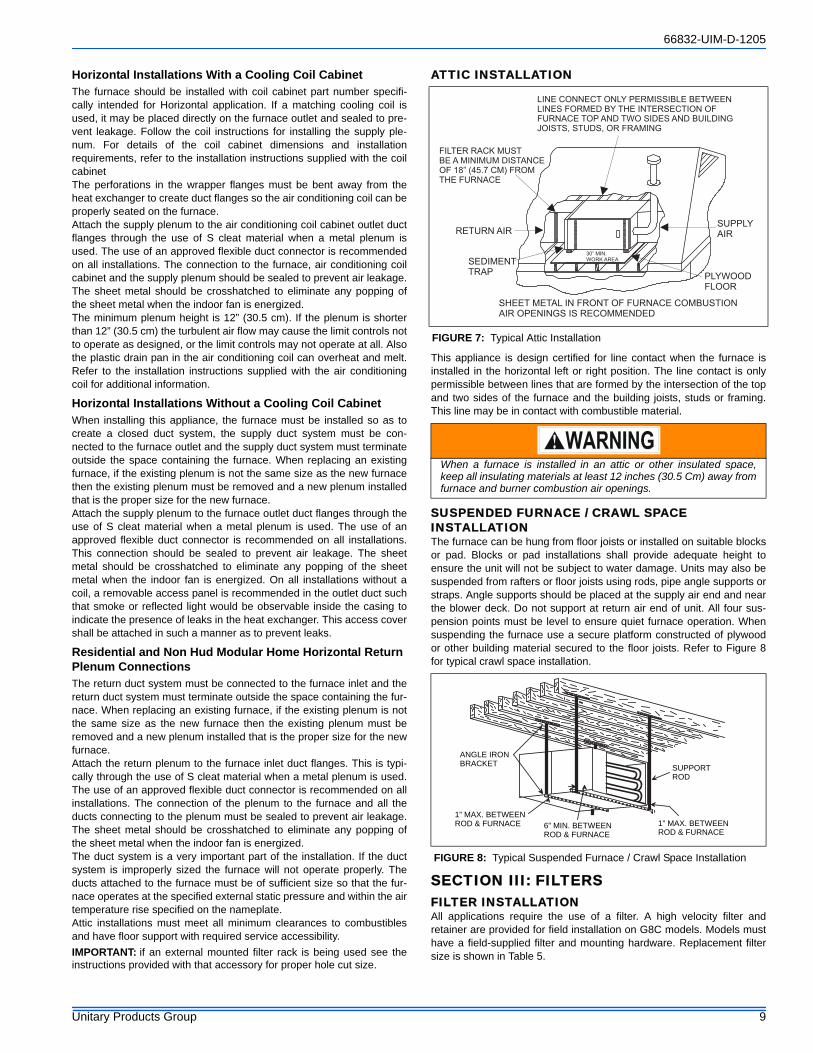
ATTIC INSTALLATION
This appliance is design certified for line contact when the furnace isinstalled in the horizontal left or right position. The line contact is onlypermissible between lines that are formed by the intersection of the topand two sides of the furnace and the building joists, studs or framing.This line may be in contact with combustible material.
SUSPENDED FURNACE / CRAWL SPACE INSTALLATIONThe furnace can be hung from floor joists or installed on suitable blocksor pad. Blocks or pad installations shall provide adequate height toensure the unit will not be subject to water damage. Units may also besuspended from rafters or floor joists using rods, pipe angle supports orstraps. Angle supports should be placed at the supply air end and nearthe blower deck. Do not support at return air end of unit. All four sus-pension points must be level to ensure quiet furnace operation. Whensuspending the furnace use a secure platform constructed of plywoodor other building material secured to the floor joists. Refer to Figure 8for typical crawl space installation.
SECTION III: FILTERSFILTER INSTALLATIONAll applications require the use of a filter. A high velocity filter andretainer are provided for field installation on G8C models. Models musthave a field-supplied filter and mounting hardware. Replacement filtersize is shown in Table 5.
FIGURE 7: Typical Attic Installation
When a furnace is installed in an attic or other insulated space,keep all insulating materials at least 12 inches (30.5 Cm) away fromfurnace and burner combustion air openings.
FIGURE 8: Typical Suspended Furnace / Crawl Space Installation
SHEET METAL IN FRONT OF FURNACE COMBUSTIONAIR OPENINGS IS RECOMMENDED
SUPPLYAIR
PLYWOODFLOOR
30” MIN.WORK AREASEDIMENT
TRAP
RETURN AIR
FILTER RACK MUSTBE A MINIMUM DISTANCEOF 18” (45.7 CM) FROMTHE FURNACE
LINE CONNECT ONLY PERMISSIBLE BETWEENLINES FORMED BY THE INTERSECTION OFFURNACE TOP AND TWO SIDES AND BUILDINGJOISTS, STUDS, OR FRAMING
ANGLE IRONBRACKET
1” MAX. BETWEENROD & FURNACE 6” MIN. BETWEEN
ROD & FURNACE 1” MAX. BETWEEN ROD & FURNACE
SUPPORT ROD
66832-UIM-D-1205
10 Unitary Products Group
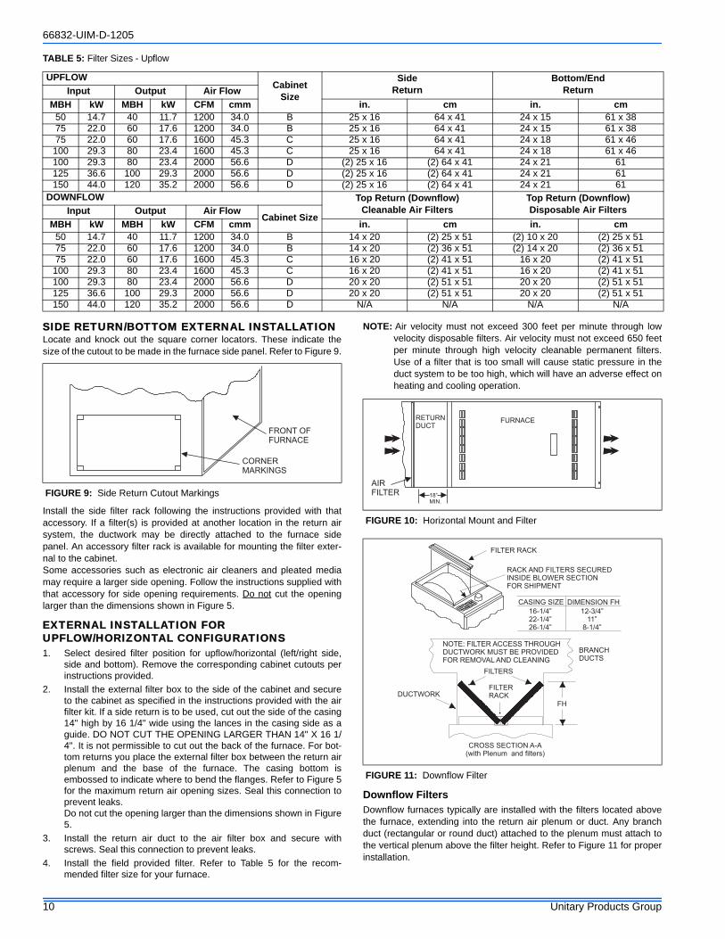
SIDE RETURN/BOTTOM EXTERNAL INSTALLATIONLocate and knock out the square corner locators. These indicate thesize of the cutout to be made in the furnace side panel. Refer to Figure 9.
Install the side filter rack following the instructions provided with thataccessory. If a filter(s) is provided at another location in the return airsystem, the ductwork may be directly attached to the furnace sidepanel. An accessory filter rack is available for mounting the filter exter-nal to the cabinet. Some accessories such as electronic air cleaners and pleated mediamay require a larger side opening. Follow the instructions supplied withthat accessory for side opening requirements. Do not cut the openinglarger than the dimensions shown in Figure 5.
EXTERNAL INSTALLATION FOR UPFLOW/HORIZONTAL CONFIGURATIONS1. Select desired filter position for upflow/horizontal (left/right side,
side and bottom). Remove the corresponding cabinet cutouts perinstructions provided.
2. Install the external filter box to the side of the cabinet and secureto the cabinet as specified in the instructions provided with the airfilter kit. If a side return is to be used, cut out the side of the casing14" high by 16 1/4" wide using the lances in the casing side as aguide. DO NOT CUT THE OPENING LARGER THAN 14" X 16 1/4". It is not permissible to cut out the back of the furnace. For bot-tom returns you place the external filter box between the return airplenum and the base of the furnace. The casing bottom isembossed to indicate where to bend the flanges. Refer to Figure 5for the maximum return air opening sizes. Seal this connection toprevent leaks.Do not cut the opening larger than the dimensions shown in Figure5.
3. Install the return air duct to the air filter box and secure withscrews. Seal this connection to prevent leaks.
4. Install the field provided filter. Refer to Table 5 for the recom-mended filter size for your furnace.
NOTE: Air velocity must not exceed 300 feet per minute through lowvelocity disposable filters. Air velocity must not exceed 650 feetper minute through high velocity cleanable permanent filters.Use of a filter that is too small will cause static pressure in theduct system to be too high, which will have an adverse effect onheating and cooling operation.
Downflow FiltersDownflow furnaces typically are installed with the filters located abovethe furnace, extending into the return air plenum or duct. Any branchduct (rectangular or round duct) attached to the plenum must attach tothe vertical plenum above the filter height. Refer to Figure 11 for properinstallation.
TABLE 5: Filter Sizes - Upflow
UPFLOWCabinet
Size
Side Return
Bottom/End ReturnInput Output Air Flow
MBH kW MBH kW CFM cmm in. cm in. cm50 14.7 40 11.7 1200 34.0 B 25 x 16 64 x 41 24 x 15 61 x 3875 22.0 60 17.6 1200 34.0 B 25 x 16 64 x 41 24 x 15 61 x 3875 22.0 60 17.6 1600 45.3 C 25 x 16 64 x 41 24 x 18 61 x 46
100 29.3 80 23.4 1600 45.3 C 25 x 16 64 x 41 24 x 18 61 x 46100 29.3 80 23.4 2000 56.6 D (2) 25 x 16 (2) 64 x 41 24 x 21 61 125 36.6 100 29.3 2000 56.6 D (2) 25 x 16 (2) 64 x 41 24 x 21 61 150 44.0 120 35.2 2000 56.6 D (2) 25 x 16 (2) 64 x 41 24 x 21 61
DOWNFLOW Top Return (Downflow) Cleanable Air Filters
Top Return (Downflow) Disposable Air FiltersInput Output Air Flow
Cabinet SizeMBH kW MBH kW CFM cmm in. cm in. cm
50 14.7 40 11.7 1200 34.0 B 14 x 20 (2) 25 x 51 (2) 10 x 20 (2) 25 x 5175 22.0 60 17.6 1200 34.0 B 14 x 20 (2) 36 x 51 (2) 14 x 20 (2) 36 x 5175 22.0 60 17.6 1600 45.3 C 16 x 20 (2) 41 x 51 16 x 20 (2) 41 x 51
100 29.3 80 23.4 1600 45.3 C 16 x 20 (2) 41 x 51 16 x 20 (2) 41 x 51100 29.3 80 23.4 2000 56.6 D 20 x 20 (2) 51 x 51 20 x 20 (2) 51 x 51125 36.6 100 29.3 2000 56.6 D 20 x 20 (2) 51 x 51 20 x 20 (2) 51 x 51150 44.0 120 35.2 2000 56.6 D N/A N/A N/A N/A
FIGURE 9: Side Return Cutout Markings
CORNERMARKINGS
FRONT OFFURNACE
FIGURE 10: Horizontal Mount and Filter
FIGURE 11: Downflow Filter
FURNACERETURNDUCT
18”MIN.
AIRFILTER
FILTER RACK
RACK AND FILTERS SECUREDINSIDE BLOWER SECTIONFOR SHIPMENT
DUCTWORK
FILTERS
BRANCHDUCTS
FH
CROSS SECTION A-A(with Plenum and filters)
FILTERRACK
NOTE: FILTER ACCESS THROUGHDUCTWORK MUST BE PROVIDEDFOR REMOVAL AND CLEANING
CASING SIZE DIMENSION FH
16-1/4”22-1/4”26-1/4”
12-3/4”11”
8-1/4”
66832-UIM-D-1205
Unitary Products Group 11
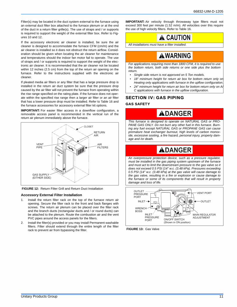
Filter(s) may be located in the duct system external to the furnace usingan external duct filter box attached to the furnace plenum or at the endof the duct in a return filter grille(s). The use of straps and / or supportsis required to support the weight of the external filter box. Refer to Fig-ures 10 and 12.If the accessory electronic air cleaner is installed, be sure the aircleaner is designed to accommodate the furnace CFM (cm/m) and theair cleaner is installed so it does not obstruct the return airflow. Consid-eration should be given when locating the air cleaner for maintenanceand temperatures should the indoor fan motor fail to operate. The useof straps and / or supports is required to support the weight of the elec-tronic air cleaner. It is recommended that the air cleaner not be locatedwithin 12 inches (2.5 cm) from the top of the return air opening on thefurnace. Refer to the instructions supplied with the electronic aircleaner.If pleated media air filters or any filter that has a large pressure drop isinstalled in the return air duct system be sure that the pressure dropcaused by the air filter will not prevent the furnace from operating withinthe rise range specified on the rating plate. If the furnace does not oper-ate within the specified rise range then a larger air filter or an air filterthat has a lower pressure drop must be installed. Refer to Table 16 andthe furnace accessories for accessory external filter kit options.IMPORTANT: For easier filter access in a downflow configuration, aremovable access panel is recommended in the vertical run of thereturn air plenum immediately above the furnace.
Accessory External Filter Installation1. Install the return filter rack on the top of the furnace return air
opening. Secure the filter rack to the front and back flanges withscrews. The return air plenum can be placed over the filter rackand the branch ducts (rectangular ducts and / or round ducts) canbe attached to the plenum. Route the combustion air and the ventPVC pipes around the access panels for the filters.
2. Install the filter(s) provided or you may install Permanent washablefilters. Filter should extend through the entire length of the filterrack to prevent air from bypassing the filter.
IMPORTANT: Air velocity through throwaway type filters must notexceed 300 feet per minute (1.52 m/m). All velocities over this requirethe use of high velocity filters. Refer to Table 16.
SECTION IV: GAS PIPINGGAS SAFETY
.
FIGURE 12: Return Filter Grill and Return Duct Installation
VENTPIPE
GAS SUPPLY(EITHER SIDE)
CLOSET
RETURNAIR
AIRFILTERS
All installations must have a filter installed.
For applications requiring more than 1800 CFM, it is required to usethe bottom return, both side returns or one side plus the bottomreturn.• Single side return is not approved on 5 Ton models.• 18” minimum height for return air box for bottom return only on
Heating only applications with furnace in the upflow configuration.• 24” minimum height for return air box for bottom return only on A/
C applications with furnace in the upflow configuration.
This furnace is designed to operate on NATURAL GAS or PRO-PANE GAS ONLY. Do not burn any other fuel in this furnace. Burn-ing any fuel except NATURAL GAS or PROPANE GAS can causepremature heat exchanger burnout, high levels of carbon monox-ide, excessive sooting, a fire hazard, personal injury, property dam-age and /or death.
An overpressure protection device, such as a pressure regulator,must be installed in the gas piping system upstream of the furnaceand must act to limit the downstream pressure to the gas valve so itdoes not exceed 0.5 PSI (14" w.c. (3.48 kPa). Pressures exceeding0.5 PSI (14” w.c. (3.48 kPa) at the gas valve will cause damage tothe gas valve, resulting in a fire or explosion or cause damage tothe furnace or some of its components that will result in propertydamage and loss of life.
FIGURE 13: Gas Valve
INLET
WRENCHBOSS
INLETPRESSUREPORT
ON
OFF
ON/OFF SWITCH(Shown in ON position)
MAIN REGULATORADJUSTMENT
OUTLET
OUTLETPRESSUREPORT
VENT PORT
66832-UIM-D-1205
12 Unitary Products Group
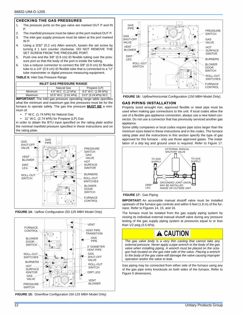
GAS PIPING INSTALLATIONProperly sized wrought iron, approved flexible or steel pipe must beused when making gas connections to the unit. If local codes allow theuse of a flexible gas appliance connection, always use a new listed con-nector. Do not use a connector that has previously serviced another gasappliance.Some utility companies or local codes require pipe sizes larger than theminimum sizes listed in these instructions and in the codes. The furnacerating plate and the instructions in this section specify the type of gasapproved for this furnace - only use those approved gases. The instal-lation of a drip leg and ground union is required. Refer to Figure 17.
IMPORTANT: An accessible manual shutoff valve must be installedupstream of the furnace gas controls and within 6 feet (1.8 m) of the fur-nace. Refer to Figures 14, 15, and 16.The furnace must be isolated from the gas supply piping system byclosing its individual external manual shutoff valve during any pressuretesting of the gas supply piping system at pressures equal to or lessthan 1/2 psig (3.5 kPa).
Gas piping may be connected from either side of the furnace using anyof the gas pipe entry knockouts on both sides of the furnace. Refer toFigure 5 dimensions.
FIGURE 14: Upflow Configuration (50-125 MBH Model Only)
FIGURE 15: Downflow Configuration (50-125 MBH Model Only)
CHECKING THE GAS PRESSURES1. The pressure ports on the gas valve are marked OUT P and IN
P. 2. The manifold pressure must be taken at the port marked OUT P. 3. The inlet gas supply pressure must be taken at the port marked
IN P. 4. Using a 3/32” (0.2 cm) Allen wrench, loosen the set screw by
turning it 1 turn counter clockwise. DO NOT REMOVE THESET SCREW FROM THE PRESSURE PORT.
5. Push one end the 3/8” (0.9 cm) ID flexible tubing over the pres-sure port so that the body of the port is inside the tubing.
6. Use a reducer connector to connect the 3/8” (0.9 cm) ID flexibletube to a 1/4” (0.9 cm) ID flexible tube that is connected to a "U”tube manometer or digital pressure measuring equipment.
IMPORTANT: The inlet gas pressure operating range table specifieswhat the minimum and maximum gas line pressures must be for thefurnace to operate safely. The gas line pressure MUST BE a mini-mum of:
• 7” W.C. (1.74 kPA) for Natural Gas• 11” W.C. (2.74 kPA) for Propane (LP) Gas
in order to obtain the BTU input specified on the rating plate and/orthe nominal manifold pressure specified in these instructions and onthe rating plate.
TABLE 6: Inlet Gas Pressure Range
INLET GAS PRESSURE RANGENatural Gas Propane (LP)
Minimum 4.5” W.C. (1.12 kPa) 8.0” W.C. (1.99 kPa)Maximum 10.5” W.C. (2.61 kPa) 13.0” (3.24 kPa) W.C.
BLOWERDOORSWITCH
ROLL-OUTSWITCHES
BURNERS
HOTSURFACEIGNITOR
GASVALVE
PRESSURESWITCH
GASPIPEGAS
SHUT-OFFVALVE
ROLL-OUTSWITCH
DIRTLEG
VENTBLOWER
FURNACECONTROL
BLOWERDOORSWITCH
ROLL-OUTSWITCHES
BURNERS
HOTSURFACEIGNITOR
GASVALVE
PRESSURESWITCH
VENT
VENT PIPETRANSITION
GASPIPE
3” DIAMETERVENT PIPE
GASSHUT-OFFVALVE
ROLL-OUTSWITCH
DIRT LEG
VENTBLOWER
FURNACECONTROL
FIGURE 16: Upflow/Horizontal Configuration (150 MBH Model Only)
FIGURE 17: Gas Piping
The gas valve body is a very thin casting that cannot take anyexternal pressure. Never apply a pipe wrench to the body of the gasvalve when installing piping. A wrench must be placed on the octa-gon hub located on the gas inlet side of the valve. Placing a wrenchto the body of the gas valve will damage the valve causing improperoperation and/or the valve to leak.
BLOWERDOORSWITCH
ROLL-OUTSWITCHES
BURNERS
HOTSURFACEIGNITOR
GASVALVE
PRESSURESWITCH
GASPIPE
GASSHUT-OFFVALVE
ROLL-OUTSWITCH
DIRTLEG
VENTBLOWER
FURNACECONTROL
EXTERNAL MANUALSHUTOFF VALVE
TO GASSUPPLY
TO GASSUPPLY
GROUNDED JOINT UNIONMAY BE INSTALLEDINSIDE OR OUTSIDE UNIT.
DRIPLEG
66832-UIM-D-1205
Unitary Products Group 13
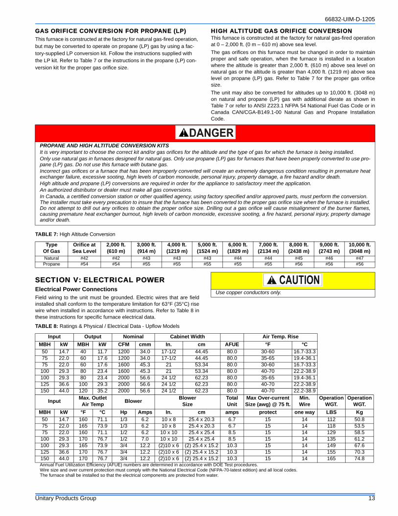
GAS ORIFICE CONVERSION FOR PROPANE (LP)This furnace is constructed at the factory for natural gas-fired operation, but may be converted to operate on propane (LP) gas by using a fac-tory-supplied LP conversion kit. Follow the instructions supplied with the LP kit. Refer to Table 7 or the instructions in the propane (LP) con-version kit for the proper gas orifice size.
HIGH ALTITUDE GAS ORIFICE CONVERSIONThis furnace is constructed at the factory for natural gas-fired operationat 0 – 2,000 ft. (0 m – 610 m) above sea level.The gas orifices on this furnace must be changed in order to maintainproper and safe operation, when the furnace is installed in a locationwhere the altitude is greater than 2,000 ft. (610 m) above sea level onnatural gas or the altitude is greater than 4,000 ft. (1219 m) above sealevel on propane (LP) gas. Refer to Table 7 for the proper gas orificesize.The unit may also be converted for altitudes up to 10,000 ft. (3048 m)on natural and propane (LP) gas with additional derate as shown inTable 7 or refer to ANSI Z223.1 NFPA 54 National Fuel Gas Code or inCanada CAN/CGA-B149.1-00 Natural Gas and Propane InstallationCode.
SECTION V: ELECTRICAL POWERElectrical Power ConnectionsField wiring to the unit must be grounded. Electric wires that are fieldinstalled shall conform to the temperature limitation for 63°F (35°C) risewire when installed in accordance with instructions. Refer to Table 8 inthese instructions for specific furnace electrical data.
Annual Fuel Utilization Efficiency (AFUE) numbers are determined in accordance with DOE Test procedures.Wire size and over current protection must comply with the National Electrical Code (NFPA-70-latest edition) and all local codes.The furnace shall be installed so that the electrical components are protected from water.
PROPANE AND HIGH ALTITUDE CONVERSION KITSIt is very important to choose the correct kit and/or gas orifices for the altitude and the type of gas for which the furnace is being installed.Only use natural gas in furnaces designed for natural gas. Only use propane (LP) gas for furnaces that have been properly converted to use pro-pane (LP) gas. Do not use this furnace with butane gas.Incorrect gas orifices or a furnace that has been improperly converted will create an extremely dangerous condition resulting in premature heatexchanger failure, excessive sooting, high levels of carbon monoxide, personal injury, property damage, a fire hazard and/or death.High altitude and propane (LP) conversions are required in order for the appliance to satisfactory meet the application.An authorized distributor or dealer must make all gas conversions.In Canada, a certified conversion station or other qualified agency, using factory specified and/or approved parts, must perform the conversion.The installer must take every precaution to insure that the furnace has been converted to the proper gas orifice size when the furnace is installed.Do not attempt to drill out any orifices to obtain the proper orifice size. Drilling out a gas orifice will cause misalignment of the burner flames,causing premature heat exchanger burnout, high levels of carbon monoxide, excessive sooting, a fire hazard, personal injury, property damageand/or death.
TABLE 7: High Altitude Conversion
Type Of Gas
Orifice at Sea Level
2,000 ft. (610 m)
3,000 ft. (914 m)
4,000 ft. (1219 m)
5,000 ft. (1524 m)
6,000 ft. (1829 m)
7,000 ft.(2134 m)
8,000 ft.(2438 m)
9,000 ft.(2743 m)
10,000 ft.(3048 m)
Natural #42 #42 #43 #43 #43 #44 #44 #45 #46 #47Propane #54 #54 #55 #55 #55 #55 #55 #56 #56 #56
Use copper conductors only.
TABLE 8: Ratings & Physical / Electrical Data - Upflow Models
Input Output Nominal Cabinet Width Air Temp. Rise MBH kW MBH kW CFM cmm In. cm AFUE °F °C
50 14.7 40 11.7 1200 34.0 17-1/2 44.45 80.0 30-60 16.7-33.375 22.0 60 17.6 1200 34.0 17-1/2 44.45 80.0 35-65 19.4-36.175 22.0 60 17.6 1600 45.3 21 53.34 80.0 30-60 16.7-33.3
100 29.3 80 23.4 1600 45.3 21 53.34 80.0 40-70 22.2-38.9100 29.3 80 23.4 2000 56.6 24 1/2 62.23 80.0 35-65 19.4-36.1125 36.6 100 29.3 2000 56.6 24 1/2 62.23 80.0 40-70 22.2-38.9150 44.0 120 35.2 2000 56.6 24 1/2 62.23 80.0 40-70 22.2-38.9
Input Max. OutletAir Temp Blower Blower
SizeTotalUnit
Max Over-currentSize (awg) @ 75 ft.
Min.Wire
OperationWGT.
OperationWGT.
MBH kW °F °C Hp Amps In. cm amps protect one way LBS Kg50 14.7 160 71.1 1/3 6.2 10 x 8 25.4 x 20.3 6.7 15 14 112 50.875 22.0 165 73.9 1/3 6.2 10 x 8 25.4 x 20.3 6.7 15 14 118 53.575 22.0 160 71.1 1/2 6.2 10 x 10 25.4 x 25.4 8.5 15 14 129 58.5
100 29.3 170 76.7 1/2 7.0 10 x 10 25.4 x 25.4 8.5 15 14 135 61.2100 29.3 165 73.9 3/4 12.2 (2)10 x 6 (2) 25.4 x 15.2 10.3 15 14 149 67.6125 36.6 170 76.7 3/4 12.2 (2)10 x 6 (2) 25.4 x 15.2 10.3 15 14 155 70.3150 44.0 170 76.7 3/4 12.2 (2)10 x 6 (2) 25.4 x 15.2 10.3 15 14 165 74.8
66832-UIM-D-1205
14 Unitary Products Group
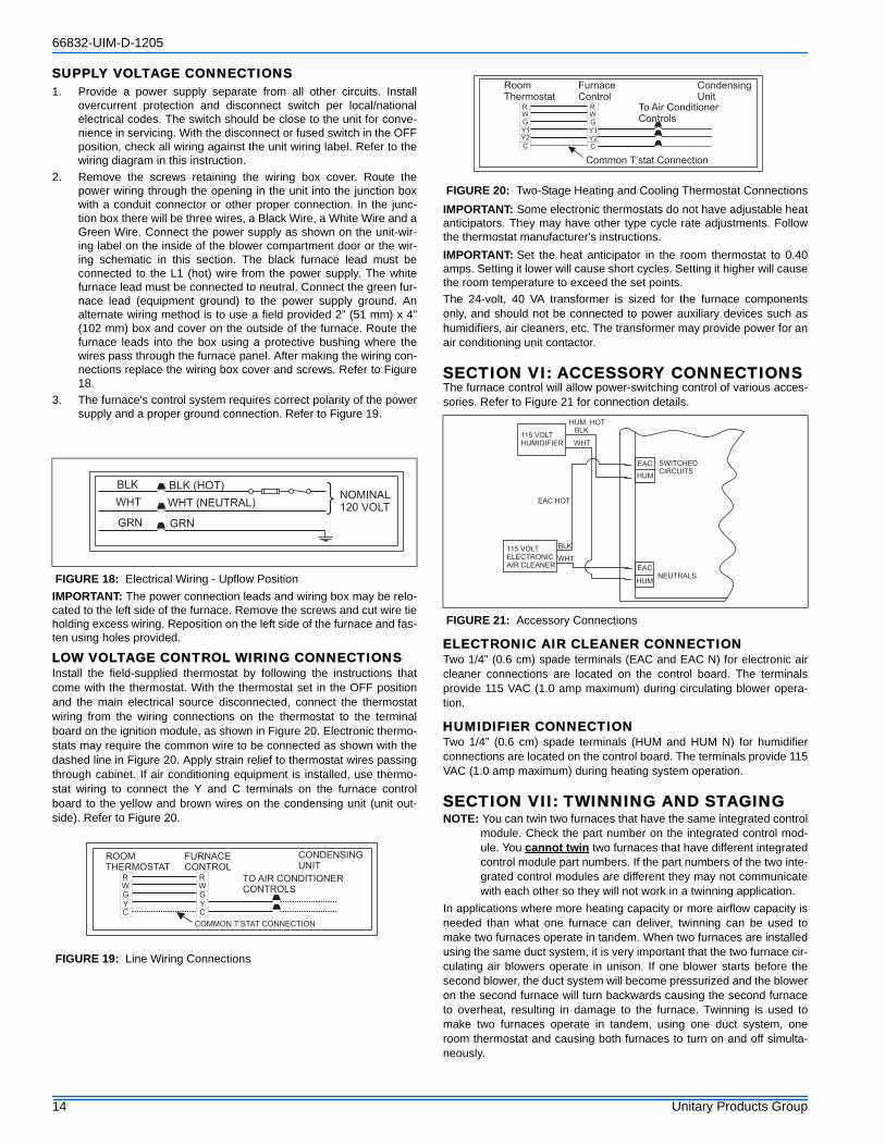
SUPPLY VOLTAGE CONNECTIONS1. Provide a power supply separate from all other circuits. Install
overcurrent protection and disconnect switch per local/nationalelectrical codes. The switch should be close to the unit for conve-nience in servicing. With the disconnect or fused switch in the OFFposition, check all wiring against the unit wiring label. Refer to thewiring diagram in this instruction.
2. Remove the screws retaining the wiring box cover. Route thepower wiring through the opening in the unit into the junction boxwith a conduit connector or other proper connection. In the junc-tion box there will be three wires, a Black Wire, a White Wire and aGreen Wire. Connect the power supply as shown on the unit-wir-ing label on the inside of the blower compartment door or the wir-ing schematic in this section. The black furnace lead must beconnected to the L1 (hot) wire from the power supply. The whitefurnace lead must be connected to neutral. Connect the green fur-nace lead (equipment ground) to the power supply ground. Analternate wiring method is to use a field provided 2” (51 mm) x 4”(102 mm) box and cover on the outside of the furnace. Route thefurnace leads into the box using a protective bushing where thewires pass through the furnace panel. After making the wiring con-nections replace the wiring box cover and screws. Refer to Figure18.
3. The furnace's control system requires correct polarity of the powersupply and a proper ground connection. Refer to Figure 19.
IMPORTANT: The power connection leads and wiring box may be relo-cated to the left side of the furnace. Remove the screws and cut wire tieholding excess wiring. Reposition on the left side of the furnace and fas-ten using holes provided.
LOW VOLTAGE CONTROL WIRING CONNECTIONSInstall the field-supplied thermostat by following the instructions thatcome with the thermostat. With the thermostat set in the OFF positionand the main electrical source disconnected, connect the thermostatwiring from the wiring connections on the thermostat to the terminalboard on the ignition module, as shown in Figure 20. Electronic thermo-stats may require the common wire to be connected as shown with thedashed line in Figure 20. Apply strain relief to thermostat wires passingthrough cabinet. If air conditioning equipment is installed, use thermo-stat wiring to connect the Y and C terminals on the furnace controlboard to the yellow and brown wires on the condensing unit (unit out-side). Refer to Figure 20.
IMPORTANT: Some electronic thermostats do not have adjustable heatanticipators. They may have other type cycle rate adjustments. Followthe thermostat manufacturer's instructions.IMPORTANT: Set the heat anticipator in the room thermostat to 0.40amps. Setting it lower will cause short cycles. Setting it higher will causethe room temperature to exceed the set points.The 24-volt, 40 VA transformer is sized for the furnace componentsonly, and should not be connected to power auxiliary devices such ashumidifiers, air cleaners, etc. The transformer may provide power for anair conditioning unit contactor.
SECTION VI: ACCESSORY CONNECTIONSThe furnace control will allow power-switching control of various acces-sories. Refer to Figure 21 for connection details.
ELECTRONIC AIR CLEANER CONNECTIONTwo 1/4” (0.6 cm) spade terminals (EAC and EAC N) for electronic aircleaner connections are located on the control board. The terminalsprovide 115 VAC (1.0 amp maximum) during circulating blower opera-tion.
HUMIDIFIER CONNECTIONTwo 1/4” (0.6 cm) spade terminals (HUM and HUM N) for humidifierconnections are located on the control board. The terminals provide 115VAC (1.0 amp maximum) during heating system operation.
SECTION VII: TWINNING AND STAGINGNOTE: You can twin two furnaces that have the same integrated control
module. Check the part number on the integrated control mod-ule. You cannot twin two furnaces that have different integratedcontrol module part numbers. If the part numbers of the two inte-grated control modules are different they may not communicatewith each other so they will not work in a twinning application.
In applications where more heating capacity or more airflow capacity isneeded than what one furnace can deliver, twinning can be used tomake two furnaces operate in tandem. When two furnaces are installedusing the same duct system, it is very important that the two furnace cir-culating air blowers operate in unison. If one blower starts before thesecond blower, the duct system will become pressurized and the bloweron the second furnace will turn backwards causing the second furnaceto overheat, resulting in damage to the furnace. Twinning is used tomake two furnaces operate in tandem, using one duct system, oneroom thermostat and causing both furnaces to turn on and off simulta-neously.
FIGURE 18: Electrical Wiring - Upflow Position
FIGURE 19: Line Wiring Connections
BLK
WHT
GRN
BLK (HOT)
WHT (NEUTRAL)
GRN
NOMINAL120 VOLT
ROOMTHERMOSTAT
FURNACECONTROL
CONDENSINGUNIT
TO AIR CONDITIONERCONTROLS
RWGYC
RWGYC
COMMON T’STAT CONNECTION
FIGURE 20: Two-Stage Heating and Cooling Thermostat Connections
FIGURE 21: Accessory Connections
RoomThermostat
FurnaceControl
CondensingUnit
To Air ConditionerControls
RWGY1
C
R
G
C
Common T’stat Connection
W
Y2Y1Y2
115 VOLTHUMIDIFIER
115 VOLTELECTRONICAIR CLEANER
BLK
WHT
EAC HOT
HUM. HOTBLK
WHT
EAC
HUM
EAC
HUMNEUTRALS
SWITCHEDCIRCUITS
66832-UIM-D-1205
Unitary Products Group 15
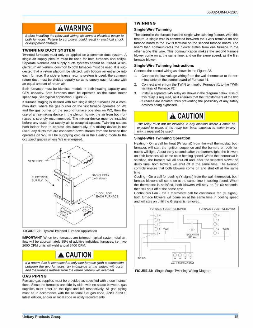
TWINNING DUCT SYSTEMTwinned furnaces must only be applied on a common duct system. Asingle air supply plenum must be used for both furnaces and coil(s).Separate plenums and supply ducts systems cannot be utilized. A sin-gle return air plenum, common to both furnaces must be used. It is sug-gested that a return platform be utilized, with bottom air entrance intoeach furnace. If a side entrance returns system is used, the commonreturn duct must be divided equally so as to supply each furnace withan equal amount of return air.Both furnaces must be identical models in both heating capacity andCFM capacity. Both furnaces must be operated on the same motorspeed tap. See typical application, Figure 22.If furnace staging is desired with two single stage furnaces on a com-mon duct, where the gas burner on the first furnace operates on W1and the gas burner on the second furnace operates on W2, then theuse of an air-mixing device in the plenum to mix the air from both fur-naces is strongly recommended. The mixing device must be installedbefore any ducts that supply air to occupied spaces. Twinning causesboth indoor fans to operate simultaneously. If a mixing device is notused, any ducts that are connected down stream from the furnace thatoperates on W2, will be supplying cold air in the Heating mode to theoccupied spaces unless W2 is energized.
IMPORTANT: When two furnaces are twinned, typical system total air-flow will be approximately 85% of additive individual furnaces, i.e., two2000 CFM units will yield a total 3400 CFM.
GAS PIPINGFurnace gas supplies must be provided as specified with these instruc-tions. Since the furnaces are side by side, with no space between, gassupplies must enter on the right and left respectively. All gas pipingmust be in accordance with the national fuel gas code, ANSI Z223.1,latest edition, and/or all local code or utility requirements.
TWINNINGSingle-Wire TwinningThe control in the furnace has the single-wire twinning feature. With thisfeature, a single wire is connected between the TWIN terminal on onefurnace board to the TWIN terminal on the second furnace board. Theboard then communicates the blower status from one furnace to theother along this wire. This communication makes the second furnaceblower come on at the same time, and on the same speed, as the firstfurnace blower.
Single-Wire Twinning InstructionsConnect the control wiring as shown in the Figure 23. 1. Connect the low voltage wiring from the wall thermostat to the ter-
minal strip on the control board of Furnace #1.2. Connect a wire from the TWIN terminal of Furnace #1 to the TWIN
terminal of Furnace #2.3. Install a separate 24V relay as shown in the diagram below. Use of
this relay is required, as it ensures that the transformers of the twofurnaces are isolated, thus preventing the possibility of any safetydevices being bypassed.
Single-Wire Twinning OperationHeating - On a call for heat (W signal) from the wall thermostat, bothfurnaces will start the ignition sequence and the burners on both fur-naces will light. About thirty seconds after the burners light, the blowerson both furnaces will come on in heating speed. When the thermostat issatisfied, the burners will all shut off and, after the selected blower offdelay time, both blowers will shut off at the same time. The twinnedcontrols ensure that both blowers come on and shut off at the sametime. Cooling - On a call for cooling (Y signal) from the wall thermostat, bothfurnace blowers will come on at the same time in cooling speed. Whenthe thermostat is satisfied, both blowers will stay on for 60 seconds,then will shut off at the same time. Continuous Fan - On a thermostat call for continuous fan (G signal),both furnace blowers will come on at the same time in cooling speedand will stay on until the G signal is removed.
Before installing the relay and wiring, disconnect electrical power toboth furnaces. Failure to cut power could result in electrical shockor equipment damage.
FIGURE 22: Typical Twinned Furnace Application
If a return duct is connected to only one furnace (with a connectionbetween the two furnaces) an imbalance in the airflow will occurand the furnace furthest from the return plenum will overheat.
VENT PIPE
ELECTRICALSUPPLY
GAS SUPPLY(both sides)
1 COIL FOREACH FURNACE
SUPPLYAIR
COMMOMSUPPLY
PLENUM
The relay must not be installed in any location where it could beexposed to water. If the relay has been exposed to water in anyway, it must not be used.
FIGURE 23: Single Stage Twinning Wiring Diagram
W
G
C
R
Y
TWIN
TO A/C
WALL THERMOSTAT
W G R Y
ISOLATIONRELAY
FURNACE 2 CONTROL BOARD
W
G
C
R
Y
TWIN
FURNACE 1 CONTROL BOARD
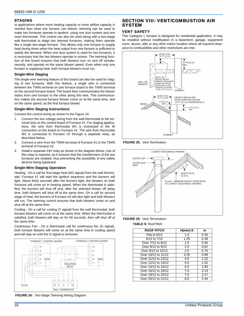
66832-UIM-D-1205
16 Unitary Products Group
STAGINGIn applications where more heating capacity or more airflow capacity isneeded than what one furnace can deliver, twinning can be used tomake two furnaces operate in tandem, using one duct system and oneroom thermostat. This control can also be used along with a two-stagewall thermostat to stage two twinned furnaces, making them operatelike a single two-stage furnace. This allows only one furnace to supplyheat during times when the heat output from one furnace is sufficient tosatisfy the demand. When one duct system is used for two furnaces, itis necessary that the two blowers operate in unison. The twinning func-tion of this board ensures that both blowers turn on and off simulta-neously, and operate on the same blower speed. Even when only onefurnace is supplying heat, both furnace blowers must run.
Single-Wire StagingThe single-wire twinning feature of this board can also be used for stag-ing of two furnaces. With this feature, a single wire is connectedbetween the TWIN terminal on one furnace board to the TWIN terminalon the second furnace board. The board then communicates the blowerstatus from one furnace to the other along this wire. This communica-tion makes the second furnace blower come on at the same time, andon the same speed, as the first furnace blower.
Single-Wire Staging InstructionsConnect the control wiring as shown in the Figure 24. 1. Connect the low voltage wiring from the wall thermostat to the ter-
minal strip on the control board of Furnace #1. For staging applica-tions, the wire from thermostat W1 is connected to the Wconnection on the board on Furnace #1. The wire from thermostatW2 is connected to Furnace #2 through a separate relay, asdescribed below.
2. Connect a wire from the TWIN terminal of Furnace #1 to the TWINterminal of Furnace #2.
3. Install a separate 24V relay as shown in the diagram below. Use ofthis relay is required, as it ensures that the transformers of the twofurnaces are isolated, thus preventing the possibility of any safetydevices being bypassed.
Single-Wire Staging OperationHeating - On a call for first-stage heat (W1 signal) from the wall thermo-stat, Furnace #1 will start the ignition sequence and the burners willlight. About thirty seconds after the burners light, the blowers on bothfurnaces will come on in heating speed. When the thermostat is satis-fied, the burners will shut off and, after the selected blower off delaytime, both blowers will shut off at the same time. On a call for secondstage of heat, the burners of Furnace #2 will also light and both blowerswill run. The twinning control ensures that both blowers come on andshut off at the same time. Cooling - On a call for cooling (Y signal) from the wall thermostat, bothfurnace blowers will come on at the same time. When the thermostat issatisfied, both blowers will stay on for 60 seconds, then will shut off atthe same time. Continuous Fan - On a thermostat call for continuous fan (G signal),both furnace blowers will come on at the same time in cooling speedand will stay on until the G signal is removed.
SECTION VIII: VENT/COMBUSTION AIR SYSTEMVENT SAFETYThis Category I, furnace is designed for residential application. It maybe installed without modification in a basement, garage, equipmentroom, alcove, attic or any other indoor location where all required clear-ance to combustibles and other restrictions are met.
FIGURE 24: Two-Stage Twinning Wiring Diagram
W
G
C
R
Y
TWIN
TO A/C
WALL THERMOSTAT
W1 G R Y
ISOLATIONRELAY
FURNACE 2 CONTROL BOARD
W
G
C
R
Y
TWIN
FURNACE 1 CONTROL BOARD
W2
FIGURE 25: Vent Termination
FIGURE 26: Vent TerminationTABLE 9: Roof Pitch
ROOF PITCH H(min) ft mFlat to 6/12 1.0 0.306/12 to 7/12 1.25 0.38
Over 7/12 to 8/12 1.5 0.46Over 8/12 to 9/12 2.0 0.61
Over 9/12 to 10/12 2.5 0.76Over 10/12 to 11/12 3.25 0.99Over 11/12 to 12/12 4.0 1.22Over 12/12 to 14/12 5.0 1.52Over 14/12 to 16/12 6.0 1.83Over 16/12 to 18/12 7.0 2.13Over 18/12 to 20/12 7.5 2.27Over 20/12 to 21/12 8.0 2.44
WALL ORPARAPET
CHIMNEY
NOTE: NOHEIGHT ABOVEPARAPET REQUIREDWHEN DISTANCEFROM WALLS ORPARAPET IS MORETHAN 10 FT (3.0 m).
3 FT (0.9 m)MIN.
MORE THAN10 FT (3.0 M)
2 FT(0.6 m)MINRIDGE
CHIMNEY
HEIGHT ABOVE ANYROOF SURFACE WITHIN10 FT (3.0 m) HORIZONTALLY
3 FT (0.9 m)MIN
MORE THAN10 FT (3.0 M)
LOWEST DISCHARGE OPENING
LISTED CAP
LISTED GASVENT
H (min) - MINIMUM HEIGHT FROM ROOFTO LOWEST DISCHARGE OPENING
12X
ROOF PITCHIS X/12

66832-UIM-D-1205
Unitary Products Group 17
CATEGORY 1 - 450 F. MAX. VENT TEMP.The venting system must be installed in accordance with Section 5.3,Air for Combustion and Ventilation, of the National Fuel Gas CodeZ223.1/NFPA 54 (latest edition), or Sections 7.2, 7.3 or 7.4 of CSAB149.1, National Gas and Propane Codes (latest edition) or applicableprovisions of the local building code and these instructions.The furnace shall be connected to any type of B, BW or L vent connec-tor, and shall be connected to a factory-built or masonry chimney. Thefurnace shall not be connected to a chimney flue serving a sepa-rate appliance designed to burn solid fuel. The furnace rating plate lists the maximum vent gas temperature. Thistemperature must be used to select the appropriate venting materialsand clearances. It is recommended that the appliance is installed in a location where thespace temperature is 32 °F (0°C) or higher. If the appliance is installedin a location where the ambient temperature is below 32 °F (0°C), theflue by-products could condense causing damage to the appliance heatexchanger.IMPORTANT: The “VENT SYSTEM” must be installed as specified inthese instructions for Residential and Non HUD Modular Homes.This appliance may be common vented with another gas appliance forresidential installations as allowed by the codes and standards listed inthese instructions.Non-HUD approved Modular Homes must be vented with a listed dou-ble wall or B-vent system and may not be common vented with otherappliances.
VENTINGCategory I venting consists of vertically venting one or more appliancesin B-vent or masonry chimney (as allowed), using single wall metal pipeor B-vent connectors. Type B-vent system extends in a general verticaldirection and does not contain offsets exceeding 45 degrees. A ventsystem having not more than one 60 degree offset is permitted.
VENTING INTO AN EXISTING CHIMNEYFor Category I installations, the furnace shall be connected to a factorybuilt chimney or vent complying with a recognized standard, or amasonry or concrete chimney lined with a material acceptable to theauthority having jurisdiction. Venting into an unlined masonry chimneyor concrete chimney is prohibited.Whenever possible, B-1 metal pipe should be used for venting. Whereuse of an existing chimney is unavoidable, the following rules must befollowed:1. The masonry chimney must be built and installed in accordance
with nationally recognized building codes or standards and mustbe lined with approved fire clay tile flue liners or other approvedliner material that will resist corrosion, softening, or cracking fromflue gases. THIS FURNACE IS NOT TO BE VENTED INTO ANUNLINED MASONRY CHIMNEY.
2. This furnace must be vented into a fire clay tile lined masonrychimney only if a source of dilution air is provided, such as by com-mon venting with a draft hood equipped water heater. If no sourceof dilution air is available, Type B vent must be used, or masonrychimney vent kit 1CK0603 or 1CK0604 must be used. Refer to theinstructions with the kit to properly apply these masonry chimneykits.
3. The chimney must extend at least three feet above the highestpoint where it passes through a roof of a building and at least twofeet higher than any portion of the building with a horizontal dis-tance of ten feet.
4. The chimney must extend at least five feet above the highestequipment draft hood or flue collar.
HORIZONTAL SIDEWALL VENTINGFor applications where vertical venting is not possible, the onlyapproved method of horizontal venting is the use of an auxiliary powervent. Approved power venters are Fields Controls Model SWG-4Y orTjernlund Model GPAK-JT. Follow all application and installation detailsprovided by the manufacturer of the power vent. Refer to Figures 29and 30 for typical installation views.
FIGURE 27: Alternate Air Intake, Air Outlet and Chimney Connections
FU
RN
AC
E
WA
TE
RH
EA
TE
R
OUTLETAIR
VENTILATION LOUVERS(each end of attic)
CHIMNEY ORGAS VENT
INLETAIR
ALTERNATEAIR INLET
VENTILATION LOUVERS FOR UNHEATED CRAWL SPACE
FIGURE 28: Air Inlet, Outlet and Chimney Connections
FU
RN
AC
E
WA
TE
RH
EA
TE
R
OUTLETAIR
VENTILATION LOUVERS(each end of attic)
CHIMNEY ORGAS VENT
INLET AIR DUCT[ends 1 ft (30 cm)above floor]
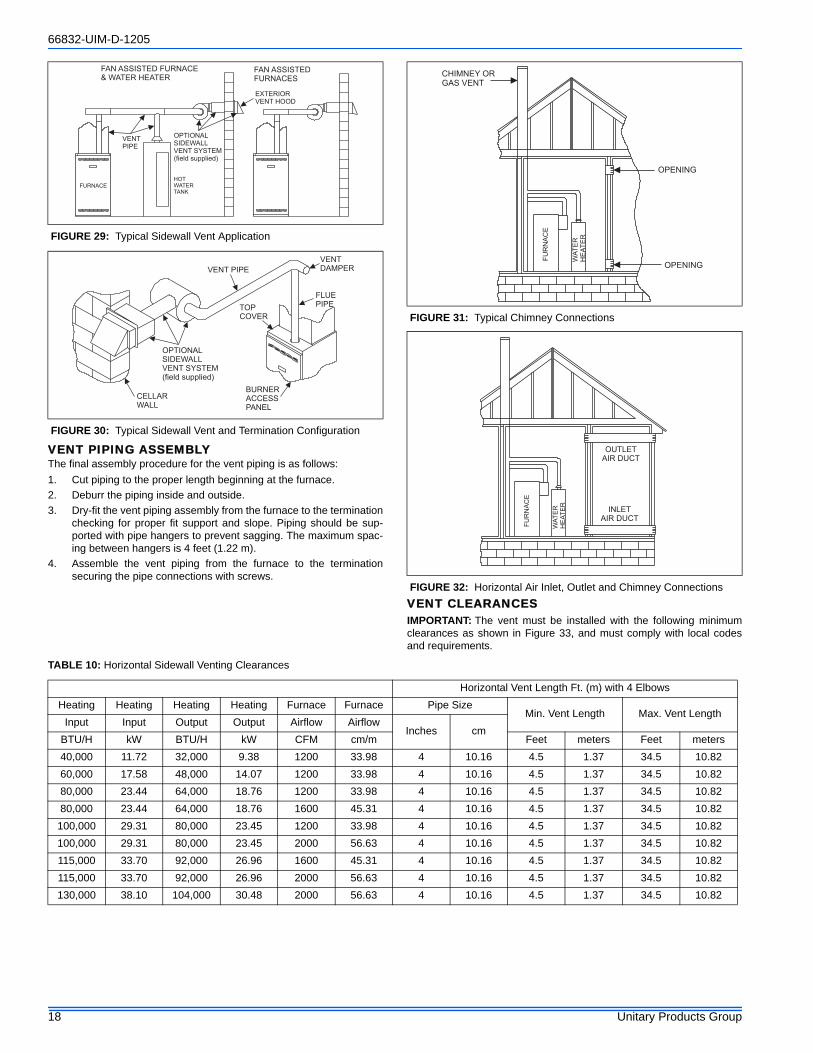
66832-UIM-D-1205
18 Unitary Products Group
VENT PIPING ASSEMBLYThe final assembly procedure for the vent piping is as follows:1. Cut piping to the proper length beginning at the furnace.2. Deburr the piping inside and outside.3. Dry-fit the vent piping assembly from the furnace to the termination
checking for proper fit support and slope. Piping should be sup-ported with pipe hangers to prevent sagging. The maximum spac-ing between hangers is 4 feet (1.22 m).
4. Assemble the vent piping from the furnace to the terminationsecuring the pipe connections with screws.
VENT CLEARANCESIMPORTANT: The vent must be installed with the following minimumclearances as shown in Figure 33, and must comply with local codesand requirements.
FIGURE 29: Typical Sidewall Vent Application
FIGURE 30: Typical Sidewall Vent and Termination Configuration
FAN ASSISTED FURNACE& WATER HEATER
FAN ASSISTEDFURNACES
VENTPIPE
HOTWATERTANK
FURNACE
OPTIONALSIDEWALLVENT SYSTEM(field supplied)
EXTERIORVENT HOOD
VENT PIPE
FLUEPIPE
BURNERACCESSPANEL
CELLARWALL
OPTIONALSIDEWALLVENT SYSTEM(field supplied)
TOPCOVER
VENTDAMPER
FIGURE 31: Typical Chimney Connections
FIGURE 32: Horizontal Air Inlet, Outlet and Chimney Connections
FU
RN
AC
E
WA
TE
RH
EA
TE
R
CHIMNEY ORGAS VENT
OPENING
OPENING
FU
RN
AC
E
WA
TE
RH
EA
TE
R
OUTLETAIR DUCT
INLETAIR DUCT
TABLE 10: Horizontal Sidewall Venting Clearances
Horizontal Vent Length Ft. (m) with 4 ElbowsHeating Heating Heating Heating Furnace Furnace Pipe Size
Min. Vent Length Max. Vent LengthInput Input Output Output Airflow Airflow
Inches cmBTU/H kW BTU/H kW CFM cm/m Feet meters Feet meters40,000 11.72 32,000 9.38 1200 33.98 4 10.16 4.5 1.37 34.5 10.8260,000 17.58 48,000 14.07 1200 33.98 4 10.16 4.5 1.37 34.5 10.8280,000 23.44 64,000 18.76 1200 33.98 4 10.16 4.5 1.37 34.5 10.8280,000 23.44 64,000 18.76 1600 45.31 4 10.16 4.5 1.37 34.5 10.82
100,000 29.31 80,000 23.45 1200 33.98 4 10.16 4.5 1.37 34.5 10.82100,000 29.31 80,000 23.45 2000 56.63 4 10.16 4.5 1.37 34.5 10.82115,000 33.70 92,000 26.96 1600 45.31 4 10.16 4.5 1.37 34.5 10.82115,000 33.70 92,000 26.96 2000 56.63 4 10.16 4.5 1.37 34.5 10.82130,000 38.10 104,000 30.48 2000 56.63 4 10.16 4.5 1.37 34.5 10.82
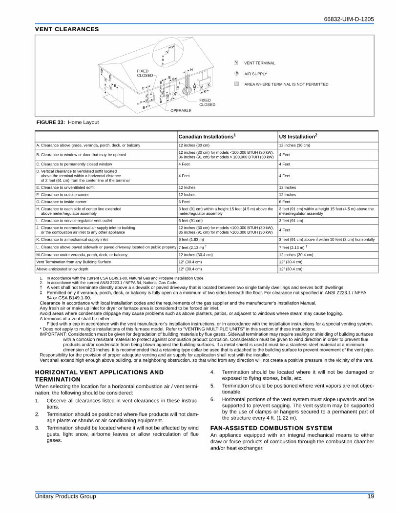
66832-UIM-D-1205
Unitary Products Group 19
VENT CLEARANCES
† A vent shall not terminate directly above a sidewalk or paved driveway that is located between two single family dwellings and serves both dwellings.‡ Permitted only if veranda, porch, deck, or balcony is fully open on a minimum of two sides beneath the floor. For clearance not specified in ANSI Z223.1 / NFPA
54 or CSA B149.1-00.Clearance in accordance with local installation codes and the requirements of the gas supplier and the manufacturer’s Installation Manual.Any fresh air or make up inlet for dryer or furnace area is considered to be forced air inlet. Avoid areas where condensate drippage may cause problems such as above planters, patios, or adjacent to windows where steam may cause fogging. A terminus of a vent shall be either:
Fitted with a cap in accordance with the vent manufacturer’s installation instructions, or In accordance with the installation instructions for a special venting system.* Does not apply to multiple installations of this furnace model. Refer to "VENTING MULTIPLE UNITS" in this section of these instructions.IMPORTANT: Consideration must be given for degradation of building materials by flue gases. Sidewall termination may require sealing or shielding of building surfaces
with a corrosion resistant material to protect against combustion product corrosion. Consideration must be given to wind direction in order to prevent flue products and/or condensate from being blown against the building surfaces. If a metal shield is used it must be a stainless steel material at a minimum dimension of 20 inches. It is recommended that a retaining type collar be used that is attached to the building surface to prevent movement of the vent pipe.
Responsibility for the provision of proper adequate venting and air supply for application shall rest with the installer.Vent shall extend high enough above building, or a neighboring obstruction, so that wind from any direction will not create a positive pressure in the vicinity of the vent.
HORIZONTAL VENT APPLICATIONS AND TERMINATIONWhen selecting the location for a horizontal combustion air / vent termi-nation, the following should be considered:1. Observe all clearances listed in vent clearances in these instruc-
tions.2. Termination should be positioned where flue products will not dam-
age plants or shrubs or air conditioning equipment.3. Termination should be located where it will not be affected by wind
gusts, light snow, airborne leaves or allow recirculation of fluegases.
4. Termination should be located where it will not be damaged orexposed to flying stones, balls, etc.
5. Termination should be positioned where vent vapors are not objec-tionable.
6. Horizontal portions of the vent system must slope upwards and besupported to prevent sagging. The vent system may be supportedby the use of clamps or hangers secured to a permanent part ofthe structure every 4 ft. (1.22 m).
FAN-ASSISTED COMBUSTION SYSTEMAn appliance equipped with an integral mechanical means to eitherdraw or force products of combustion through the combustion chamberand/or heat exchanger.
FIGURE 33: Home Layout
L
E
D
B
V
V VX
V
B
VJ
X
B
B
B
V
VF
V
C
B
X
V
I
V
G
H
A
M
K
OPERABLE
FIXEDCLOSED
VENT TERMINAL
AIR SUPPLY
AREA WHERE TERMINAL IS NOT PERMITTED
FIXEDCLOSED
Canadian Installations1 US Installation2
A. Clearance above grade, veranda, porch, deck, or balcony 12 inches (30 cm) 12 inches (30 cm)
B. Clearance to window or door that may be opened 12 inches (30 cm) for models <100,000 BTUH (30 kW), 36 inches (91 cm) for models > 100,000 BTUH (30 kW) 4 Feet
C. Clearance to permanently closed window 4 Feet 4 Feet
D. Vertical clearance to ventilated soffit located above the terminal within a horizontal distance of 2 feet (61 cm) from the center line of the terminal
4 Feet 4 Feet
E. Clearance to unventilated soffit 12 Inches 12 Inches
F. Clearance to outside corner 12 Inches 12 Inches
G. Clearance to inside corner 6 Feet 6 Feet
H. Clearance to each side of center line extended above meter/regulator assembly
3 feet (91 cm) within a height 15 feet (4.5 m) above the meter/regulator assembly
3 feet (91 cm) within a height 15 feet (4.5 m) above the meter/regulator assembly
I. Clearance to service regulator vent outlet 3 feet (91 cm) 3 feet (91 cm)
J. Clearance to nonmechanical air supply inlet to building or the combustion air inlet to any other appliance
12 inches (30 cm) for models <100,000 BTUH (30 kW), 35 inches (91 cm) for models >100,000 BTUH (30 kW) 4 Feet
K. Clearance to a mechanical supply inlet 6 feet (1.83 m) 3 feet (91 cm) above if within 10 feet (3 cm) horizontally
L. Clearance above paved sidewalk or paved driveway located on public property 7 feet (2.13 m) † 7 feet (2.13 m) †
M.Clearance under veranda, porch, deck, or balcony 12 inches (30.4 cm) 12 inches (30.4 cm)
Vent Termination from any Building Surface 12" (30.4 cm) 12" (30.4 cm)
Above anticipated snow depth 12" (30.4 cm) 12" (30.4 cm)
1. In accordance with the current CSA B149.1-00, Natural Gas and Propane Installation Code.2. In accordance with the current ANSI Z223.1 / NFPA 54, National Gas Code.
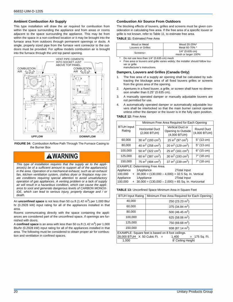
66832-UIM-D-1205
20 Unitary Products Group
Ambient Combustion Air Supply This type installation will draw the air required for combustion fromwithin the space surrounding the appliance and from areas or roomsadjacent to the space surrounding the appliance. This may be fromwithin the space in a non-confined location or it may be brought into thefurnace area from outdoors through permanent openings or ducts. Asingle, properly sized pipe from the furnace vent connector to the out-doors must be provided. For upflow models combustion air is broughtinto the furnace through the unit top panel opening.
An unconfined space is not less than 50 cu.ft (1.42 m3) per 1,000 Btu/hr (0.2928 kW) input rating for all of the appliances installed in thatarea.Rooms communicating directly with the space containing the appli-ances are considered part of the unconfined space, if openings are fur-nished with doors.A confined space is an area with less than 50 cu.ft (1.42 m3) per 1,000Btu/hr (0.2928 kW) input rating for all of the appliances installed in thatarea. The following must be considered to obtain proper air for combus-tion and ventilation in confined spaces.
Combustion Air Source From OutdoorsThe blocking effects of louvers, grilles and screens must be given con-sideration in calculating free area. If the free area of a specific louver orgrille is not known, refer to Table 11, to estimate free area.
* Do not use less than 1/4” (0.635 cm) mesh+ Free area or louvers and grille varies widely; the installer should follow lou-
ver or grille manufacturer’s instructions.
Dampers, Louvers and Grilles (Canada Only)1. The free area of a supply air opening shall be calculated by sub-
tracting the blockage area of all fixed louvers grilles or screensfrom the gross area of the opening.
2. Apertures in a fixed louver, a grille, or screen shall have no dimen-sion smaller than 0.25” (0.635 cm).
3. A manually operated damper or manually adjustable louvers arenot permitted for use.
4. A automatically operated damper or automatically adjustable lou-vers shall be interlocked so that the main burner cannot operateunless either the damper or the louver is in the fully open position.
FIGURE 34: Combustion Airflow Path Through The Furnace Casing to the Burner Box
This type of installation requires that the supply air to the appli-ance(s) be of a sufficient amount to support all of the appliance(s)in the area. Operation of a mechanical exhaust, such as an exhaustfan, kitchen ventilation system, clothes dryer or fireplace may cre-ate conditions requiring special attention to avoid unsatisfactoryoperation of gas appliances. A venting problem or a lack of supplyair will result in a hazardous condition, which can cause the appli-ance to soot and generate dangerous levels of CARBON MONOX-IDE, which can lead to serious injury, property damage and / ordeath.
COMBUSTIONAIR
VENT PIPE CEMENTSINTO SOCKET JUSTABOVE TOP PANEL
COMBUSTIONAIR
DOWNFLOWUPFLOW
TABLE 11: Estimated Free Area
Wood or MetalLouvers or Grilles
Wood 20-25%*Metal 60-70% *
Screens+ 1/4” (0.635 cm)mesh or larger 100%
TABLE 12: Free Area
BTUH InputRating
Minimum Free Area Required for Each Opening
Horizontal Duct(2,000 BTUH)
Vertical Duct orOpening to Outside
(4,000 BTUH)
Round Duct(4,000 BTUH)
60,000 30 in2 (193 cm2) 15 in2 (97 cm2) 5” (13 cm)
80,000 40 in2 (258 cm2) 20 in2 (129 cm2) 5” (13 cm)
100,000 50 in2 (322 cm2) 25 in2 (161 cm2) 6” (15 cm)
125,000 60 in2 (387 cm2) 30 in2 (193 cm2) 7” (18 cm)
150,000 75 in2 (484 cm2) 37 in2 (239 cm2) 7” (18 cm)EXAMPLE: Determining Free Area.Appliance 1Appliance 2Total Input100,000 + 30,000 = (130,000 ÷ 4,000) = 32.5 Sq. In. VerticalAppliance 1Appliance 2Total Input100,000 + 30,000 = (130,000 ÷ 2,000) = 65 Sq. In. Horizontal
TABLE 13: Unconfined Space Minimum Area in Square Feet
BTUH Input Rating Minimum Free Area Required for Each Opening40,000 250 (23.23 m2)60,000 375 (34.84 m2)80,000 500 (46.45 m2)
100,000 625 (58.06 m2)125,000 750 (69.68 m2)150,000 938 (87.14 m2)
EXAMPLE: Square feet is based on 8 foot ceilings.28,000 BTUH X 50 Cubic Ft. = 1,400 = 175 Sq. Ft. 1,000 8’ Ceiling Height
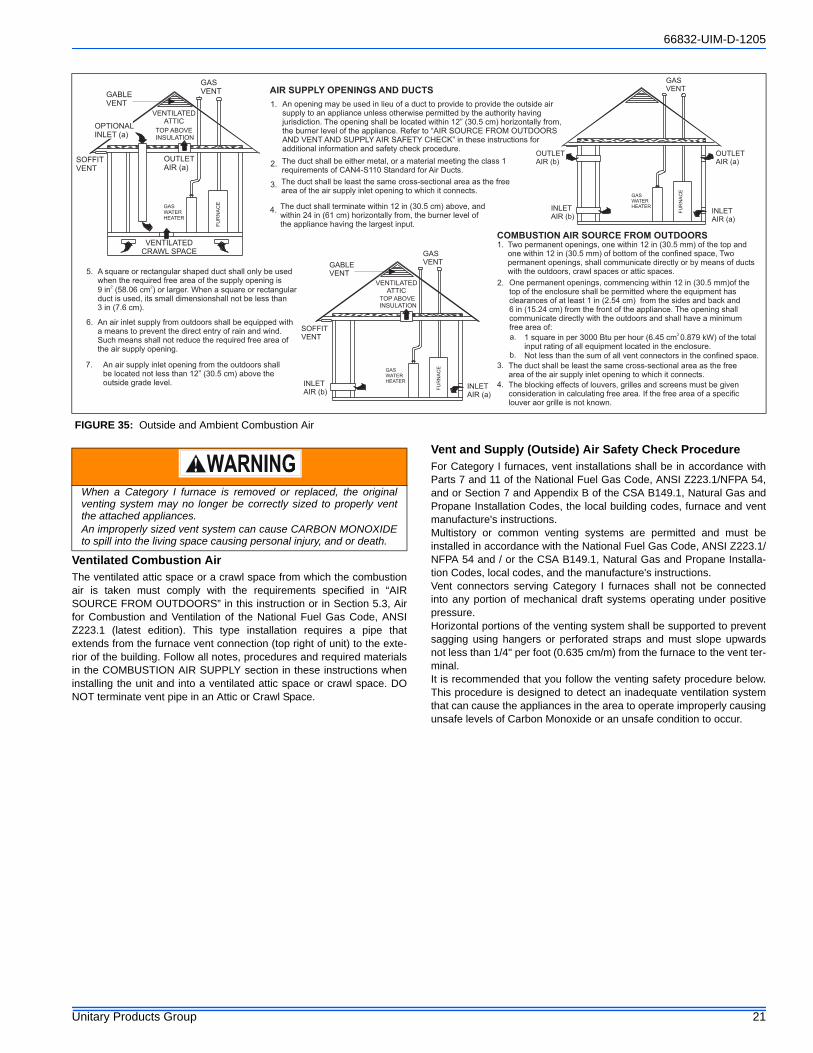
66832-UIM-D-1205
Unitary Products Group 21
Ventilated Combustion AirThe ventilated attic space or a crawl space from which the combustionair is taken must comply with the requirements specified in “AIRSOURCE FROM OUTDOORS” in this instruction or in Section 5.3, Airfor Combustion and Ventilation of the National Fuel Gas Code, ANSIZ223.1 (latest edition). This type installation requires a pipe thatextends from the furnace vent connection (top right of unit) to the exte-rior of the building. Follow all notes, procedures and required materialsin the COMBUSTION AIR SUPPLY section in these instructions wheninstalling the unit and into a ventilated attic space or crawl space. DONOT terminate vent pipe in an Attic or Crawl Space.
Vent and Supply (Outside) Air Safety Check ProcedureFor Category I furnaces, vent installations shall be in accordance withParts 7 and 11 of the National Fuel Gas Code, ANSI Z223.1/NFPA 54,and or Section 7 and Appendix B of the CSA B149.1, Natural Gas andPropane Installation Codes, the local building codes, furnace and ventmanufacture's instructions.Multistory or common venting systems are permitted and must beinstalled in accordance with the National Fuel Gas Code, ANSI Z223.1/NFPA 54 and / or the CSA B149.1, Natural Gas and Propane Installa-tion Codes, local codes, and the manufacture's instructions. Vent connectors serving Category I furnaces shall not be connectedinto any portion of mechanical draft systems operating under positivepressure.Horizontal portions of the venting system shall be supported to preventsagging using hangers or perforated straps and must slope upwardsnot less than 1/4" per foot (0.635 cm/m) from the furnace to the vent ter-minal.It is recommended that you follow the venting safety procedure below.This procedure is designed to detect an inadequate ventilation systemthat can cause the appliances in the area to operate improperly causingunsafe levels of Carbon Monoxide or an unsafe condition to occur.
FIGURE 35: Outside and Ambient Combustion Air
GABLEVENT
GASVENT
SOFFITVENT
VENTILATEDATTIC
TOP ABOVEINSULATION
OPTIONALINLET (a)
OUTLETAIR (a)
VENTILATEDCRAWL SPACE
GASWATERHEATER
VENTILATEDATTIC
TOP ABOVEINSULATION
GASVENTGABLE
VENT
SOFFITVENT
GASWATERHEATER
INLETAIR (a)
INLETAIR (b)
GASVENT
OUTLETAIR (a)
OUTLETAIR (b)
INLETAIR (a)
INLETAIR (b)
GASWATERHEATER
FU
RN
AC
E
FU
RN
AC
E
FU
RN
AC
E
1. An opening may be used in lieu of a duct to provide to provide the outside airsupply to an appliance unless otherwise permitted by the authority havingjurisdiction. The opening shall be located within 12” (30.5 cm) horizontally from,the burner level of the appliance. Refer to “AIR SOURCE FROM OUTDOORSAND VENT AND SUPPLY AIR SAFETY CHECK” in these instructions foradditional information and safety check procedure.
2. The duct shall be either metal, or a material meeting the class 1requirements of CAN4-S110 Standard for Air Ducts.
3. The duct shall be least the same cross-sectional area as the freearea of the air supply inlet opening to which it connects.
4. The duct shall terminate within 12 in (30.5 cm) above, andwithin 24 in (61 cm) horizontally from, the burner level ofthe appliance having the largest input.
5. A square or rectangular shaped duct shall only be usedwhen the required free area of the supply opening is9 in (58.06 cm ) or larger. When a square or rectangularduct is used, its small dimensionshall not be less than3 in (7.6 cm).
2 2
6. An air inlet supply from outdoors shall be equipped witha means to prevent the direct entry of rain and wind.Such means shall not reduce the required free area ofthe air supply opening.
7. An air supply inlet opening from the outdoors shallbe located not less than 12” (30.5 cm) above theoutside grade level.
AIR SUPPLY OPENINGS AND DUCTS
COMBUSTION AIR SOURCE FROM OUTDOORS
1. Two permanent openings, one within 12 in (30.5 mm) of the top andone within 12 in (30.5 mm) of bottom of the confined space,
shall communicate directly or by means of ductswith the outdoors, crawl spaces or attic spaces.
Twopermanent openings,
2. One permanent openings, commencing within 12 in (30.5 mm)of thetop of the enclosure shall be permitted where the equipment hasclearances of at least 1 in (2.54 cm) from the sides and back and6 in (15.24 cm) from the front of the appliance. The opening shallcommunicate directly with the outdoors and shall have a minimumfree area of:
3. The duct shall be least the same cross-sectional area as the freearea of the air supply inlet opening to which it connects.
1 square in per 3000 Btu per hour (6.45 cm 0.879 kW) of the totalinput rating of all equipment located in the enclosure.
2a.
Not less than the sum of all vent connectors in the confined space.b.
4. The blocking effects of louvers, grilles and screens must be givenconsideration in calculating free area. If the free area of a specificlouver aor grille is not known.
When a Category I furnace is removed or replaced, the originalventing system may no longer be correctly sized to properly ventthe attached appliances. An improperly sized vent system can cause CARBON MONOXIDEto spill into the living space causing personal injury, and or death.
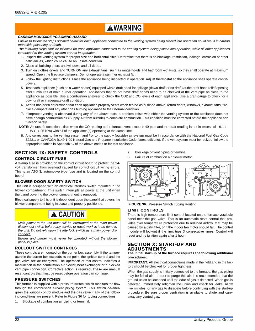
66832-UIM-D-1205
22 Unitary Products Group
SECTION IX: SAFETY CONTROLSCONTROL CIRCUIT FUSEA 3-amp fuse is provided on the control circuit board to protect the 24-volt transformer from overload caused by control circuit wiring errors.This is an ATO 3, automotive type fuse and is located on the controlboard.
BLOWER DOOR SAFETY SWITCHThis unit is equipped with an electrical interlock switch mounted in theblower compartment. This switch interrupts all power at the unit whenthe panel covering the blower compartment is removed.Electrical supply to this unit is dependent upon the panel that covers theblower compartment being in place and properly positioned.
ROLLOUT SWITCH CONTROLSThese controls are mounted on the burner box assembly. If the temper-ature in the burner box exceeds its set point, the ignition control and thegas valve are de-energized. The operation of this control indicates amalfunction in the combustion air blower, heat exchanger or a blockedvent pipe connection. Corrective action is required. These are manualreset controls that must be reset before operation can continue.
PRESSURE SWITCHESThis furnace is supplied with a pressure switch, which monitors the flowthrough the combustion air/vent piping system. This switch de-ener-gizes the ignition control module and the gas valve if any of the follow-ing conditions are present. Refer to Figure 36 for tubing connections.1. Blockage of combustion air piping or terminal.
2. Blockage of vent piping or terminal.3. Failure of combustion air blower motor.
LIMIT CONTROLSThere is high temperature limit control located on the furnace vestibulepanel near the gas valve. This is an automatic reset control that pro-vides over temperature protection due to reduced airflow, that may becaused by a dirty filter, or if the indoor fan motor should fail. The controlmodule will lockout if the limit trips 3 consecutive times. Control willreset and try ignition again after 1 hour.
SECTION X: START-UP AND ADJUSTMENTSThe initial start-up of the furnace requires the following additionalprocedures:IMPORTANT: All electrical connections made in the field and in the fac-tory should be checked for proper tightness.When the gas supply is initially connected to the furnace, the gas pipingmay be full of air. In order to purge this air, it is recommended that theground union be loosened until the odor of gas is detected. When gas isdetected, immediately retighten the union and check for leaks. Allowfive minutes for any gas to dissipate before continuing with the start-upprocedure. Be sure proper ventilation is available to dilute and carryaway any vented gas.
CARBON MONOXIDE POISONING HAZARDFailure to follow the steps outlined below for each appliance connected to the venting system being placed into operation could result in carbonmonoxide poisoning or death.The following steps shall be followed for each appliance connected to the venting system being placed into operation, while all other appliancesconnected to the venting system are not in operation:
1. Inspect the venting system for proper size and horizontal pitch. Determine that there is no blockage, restriction, leakage, corrosion or otherdeficiencies, which could cause an unsafe condition
2. Close all building doors and windows and all doors.3. Turn on clothes dryers and TURN ON any exhaust fans, such as range hoods and bathroom exhausts, so they shall operate at maximum
speed. Open the fireplace dampers. Do not operate a summer exhaust fan.4. Follow the lighting instructions. Place the appliance being inspected in operation. Adjust thermostat so the appliance shall operate contin-
uously.5. Test each appliance (such as a water heater) equipped with a draft hood for spillage (down-draft or no draft) at the draft hood relief opening
after 5 minutes of main burner operation. Appliances that do not have draft hoods need to be checked at the vent pipe as close to theappliance as possible. Use a combustion analyzer to check the CO2 and CO levels of each appliance. Use a draft gauge to check for adowndraft or inadequate draft condition.
6. After it has been determined that each appliance properly vents when tested as outlined above, return doors, windows, exhaust fans, fire-place dampers and any other gas burning appliance to their normal condition.
7. If improper venting is observed during any of the above tests, a problem exists with either the venting system or the appliance does nothave enough combustion air (Supply Air from outside) to complete combustion. This condition must be corrected before the appliance canfunction safely.
NOTE: An unsafe condition exists when the CO reading at the furnace vent exceeds 40 ppm and the draft reading is not in excess of - 0.1 in.W.C. (-25 kPa) with all of the appliance(s) operating at the same time.
8. Any corrections to the venting system and / or to the supply (outside) air system must be in accordance with the National Fuel Gas CodeZ223.1 or CAN/CGA B149.1-00 Natural Gas and Propane Installation Code (latest editions). If the vent system must be resized, follow theappropriate tables in Appendix G of the above codes or for this appliance.
Main power to the unit must still be interrupted at the main powerdisconnect switch before any service or repair work is to be done tothe unit. Do not rely upon the interlock switch as a main power dis-connect.Blower and burner must never be operated without the blowerpanel in place.
FIGURE 36: Pressure Switch Tubing Routing
66832-UIM-D-1205
Unitary Products Group 23
TOOLS AND INFORMATION THAT WILL BE REQUIRED IN ORDER TO PROPERLY PERFORM THE FURNACE STARTUP PROCEDURE.1. Call the local gas supplier to obtain heating value of the natural
gas. If you cannot obtain the heating valve of the gas from the gassupplier, you may use a default value of 1030 BTU/SCF (38.8 MJ /m³).
2. You will need a thermometer or portable digital thermometer toread the supply and return air temperatures.
3. You will need a U-tube manometer or digital equipment that hasthe ability to read pressures between 0 – 15” in.w.c (0 - 3.73 kPa)in order to measure the gas line and the manifold pressures.
4. You will need a 3/32” Allen wrench for the pressure port plugs inthe gas valve.
5. You will need 2 pieces of 1/8” (0.3 cm) ID flexible tubing that is 12”(30 cm) in length, 2 – pieces of 1/8” (0.3 cm) tubing that are 4”(10.0 cm) in length, a 1/8” (0.3 cm) tee and a 1/8” (0.3 cm) adapterto connect the U-tube manometer or the digital pressure measur-ing equipment to the gas valve pressure ports.
There is an accessory kit (1PK0601) available from Source 1, whichhas the following items:
• 1 - 12” (30 cm) length x 1/8” (0.3 cm) diameter tubing• 2 – pieces of 4” (10 cm) length x 1/8” (0.3 cm) diameter tubing• 1 - 5/16” (0.8 cm) tee• 1 – 5/16” (0.8 cm) x 1/8” (0.3 cm) reducing coupling• 1 – 1/8” (0.3 cm) adapter
There is a accessory kit (1PK0602) available from Source 1, which hasthe following items:
• 12” (30 cm) length x 1/8” (0.3 cm) diameter tubing• 2 – pieces of 4” (10 cm) length x 1/8” (0.3 cm) diameter tubing• 1 - 5/16” (0.8 cm) tee• 1 – 5/16” (0.8 cm) x 1/8” (0.3 cm) reducing coupling• 1 – 1/8” (0.3 cm) adapter• 1 - Dwyer – Manometer
These items are required in order to properly perform the required start-up procedure.
IGNITION SYSTEM SEQUENCE1. Turn the gas supply ON at external valve and main gas valve.2. Set the thermostat above room temperature to call for heat.3. System start-up will occur as follows:
a. The induced draft blower motor will start and come up tospeed. Shortly after inducer start-up, the hot surface ignitorwill glow for about 17 seconds.
b. After this warm up, the ignition module will energize (open)the main gas valve.
c. After flame is established, the supply air blower will start inabout 30 seconds.
IMPORTANT: Burner ignition may not be satisfactory on first startupdue to residual air in the gas line or until gas manifold pressure isadjusted. The ignition control will make 3 attempts to light before lock-ing out.With furnace in operation, check all of the pipe joints, gas valve connec-tions and manual valve connections for leakage using an approved gasdetector, a non-corrosive leak detection fluid, or other leak detectionmethods. Take appropriate steps to stop any leak. If a leak persists,replace the component.The furnace and its equipment shutoff valve must be disconnected fromthe gas supply piping system during any pressure testing of that systemat test pressures in excess of 1/2 PSI (3.45 kPa).The furnace must be isolated from the gas supply piping system byclosing the equipment shutoff valve during any pressure testing of thegas supply piping system.
CALCULATING THE FURNACE INPUT (NATURAL GAS)NOTE: Burner orifices are sized to provide proper input rate using natu-
ral gas with a heating value of 1030 BTU/Ft3. If the heatingvalue of your gas is significantly different, it may be necessary toreplace the orifices.
1. Turn off all other gas appliances connected to the gas meter.2. At the gas meter, measure the time (with a stop watch) it takes to
use 2 cubic ft. (0.0566 m3.) of gas.3. Calculate the furnace input by using one of the following equa-
tions.
FIRE OR EXPLOSION HAZARDFailure to follow the safety warnings exactly could result in seriousinjury, death or property damage.Never test for gas leaks with an open flame. Use a commerciallyavailable soap solution made specifically for the detection of leaksto check all connections. A fire or explosion may result causingproperty damage, personal injury or loss of life.
TABLE 14: Field Installed Accessories - Non Electrical
PART NO. DESCRIPTION USED WITH1FB0318
Combustible Floor Sub-Base50, 7512
1FB0319 7516,100161FB0320 10020,1251BR0312
Bottom Filter Rack50,7512
1BR0316 7516,100161BR0320 10020,125,1501NP0366 Conversion Kit-Natural Gas to LP Gas
All Models1NP0367 Conversion Kit- Natural Gas to LP Gas- High Altitude2802-321P Vent Pipe Extension
66832-UIM-D-1205
24 Unitary Products Group
In the USA use the following formula to calculate the furnace input.For natural gas multiply the heat content of the gas BTU/SCF (or Default 1030 BTU/SCF, times 2 cubic ft. of gas measured at the gas meter, times abarometric pressure and temperature correction factor of 0.960; times 3600, then divided by the time (In seconds) it took to measure 2 cubic ft. of gasfrom the gas meter.For propane (LP) gas multiply the heat content of the gas BTU/SCF (or Default 2500 BTU/SCF, times 1 cubic ft. of gas measured at the gas meter,times a barometric pressure and temperature correction factor of 0.960; times 3600, then divided by the time (In seconds) it took to measure 1 cubicft. of gas from the gas meter.
The formula for US input calculation using a cubic foot gas meter:
In Canada you will use the following formula to calculate the furnace input if you are using a cubic foot gas meter.For Natural Gas multiply the Heat content of the gas MJ/m3 (or Default 39.2), times 2 cu. ft. of gas x 0.02831 to convert from cubic feet to cubicmeters measured at the gas meter, times a barometric pressure and temperature correction factor of 0.960; times 3600, then divided by the time ittook to measure 2 cu.ft. of gas from the gas meter.For Propane (LP) Gas multiply the Heat content of the gas MJ/m3 (or Default 93.14), times 1 cu. ft. of gas x 0.02831 to convert from cubic feet tocubic meters measured at the gas meter, times a barometric pressure and temperature correction factor of 0.960; times 3600, then divided by thetime it took to measure 1 cu.ft. of gas from the gas meter.
The formula for metric input calculation using a cubic foot gas meter:
In Canada use the following formula to calculate the furnace input if you are using a gas meter that measures cubic meters.For Natural Gas multiply the Heat content of the gas MJ/m3 (or Default 39.2), times 0.0566 m3 of gas measured at the gas meter, times a barometricpressure and temperature correction factor of 0.960; times 3600, then divided by the time it took to measure 0.0566 m3 of gas from the gas meter.For Propane (LP) Gas multiply the Heat content of the gas MJ/m3 (or Default 93.14), times 0.00283 m3 of gas measured at the gas meter, times abarometric pressure and temperature correction factor of 0.960; times 3600, then divided by the time it took to measure 0.0283 cm of gas from thegas meter.
The formula for metric input calculation using a cubic foot gas meter:
DO NOT ADJUST the manifold pressure regulator if the actual input is equal to or within 8% less than the furnace input specified on the rating plateor if the furnace rise is above the specified rise range on the rating plate.If the actual input is significantly higher than the furnace input specified on the rating plate then replace the gas orifice spuds with the gas ori-fice spuds of the proper size for the type of gas you are using.
BTU/f3 x 2 cu.ft. x 0.960 x 3600 = BTUH/H BTU/f3 x 1 cu.ft. x 0.960 x 3600 = BTUH/HSeconds it took to measure the 2 cu.ft. of gas Seconds it took to measure the 2 cu.ft. of gasNATURAL GAS INPUT CALCULATION PROPANE (LP) GAS INPUT CALCULATIONEXAMPLE: EXAMPLE:
1030 x 2 x 0.960 x 3600 = 79,997.38 2500 x 1 x 0.960 x 3600 = 80,000.0090.5 108Natural Gas Propane Gas
BTU/SCF 1030 BTU/SCF 2500
MJ/m3 x (2 cu.ft. x Conv) x 0.960 x 3600 = MJ/H x 0.2777 = kW x 3412.14 = BTUH/HSeconds it took to measure the 2 cu.ft. of gasNATURAL GAS INPUT CALCULATIONEXAMPLE:
39.2 x 2 x 0.960 x 3600 = 84.76 x 0.2777 = 23.54 x 3412.14 = 80,312.6290.5Natural Gas
BTU/SCF 1030 = 39.2 MJ/m3
PROPANE (LP) GAS INPUT CALCULATIONEXAMPLE:
93.15 x 1 x 0.960 x 3600 = 84.41 x 0.2777 = 23.45 x 3412.14 = 80,000.00108Propane Gas
BTU/SCF 2500+93.15 MJ/m3
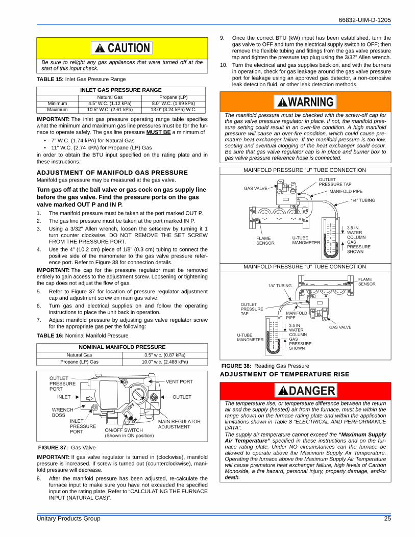
66832-UIM-D-1205
Unitary Products Group 25
IMPORTANT: The inlet gas pressure operating range table specifieswhat the minimum and maximum gas line pressures must be for the fur-nace to operate safely. The gas line pressure MUST BE a minimum of
• 7” W.C. (1.74 kPA) for Natural Gas• 11” W.C. (2.74 kPA) for Propane (LP) Gas
in order to obtain the BTU input specified on the rating plate and inthese instructions.
ADJUSTMENT OF MANIFOLD GAS PRESSUREManifold gas pressure may be measured at the gas valve.
Turn gas off at the ball valve or gas cock on gas supply line before the gas valve. Find the pressure ports on the gas valve marked OUT P and IN P.1. The manifold pressure must be taken at the port marked OUT P. 2. The gas line pressure must be taken at the port marked IN P.3. Using a 3/32” Allen wrench, loosen the setscrew by turning it 1
turn counter clockwise. DO NOT REMOVE THE SET SCREWFROM THE PRESSURE PORT.
4. Use the 4” (10.2 cm) piece of 1/8” (0.3 cm) tubing to connect thepositive side of the manometer to the gas valve pressure refer-ence port. Refer to Figure 38 for connection details.
IMPORTANT: The cap for the pressure regulator must be removedentirely to gain access to the adjustment screw. Loosening or tighteningthe cap does not adjust the flow of gas.5. Refer to Figure 37 for location of pressure regulator adjustment
cap and adjustment screw on main gas valve.6. Turn gas and electrical supplies on and follow the operating
instructions to place the unit back in operation.7. Adjust manifold pressure by adjusting gas valve regulator screw
for the appropriate gas per the following:
IMPORTANT: If gas valve regulator is turned in (clockwise), manifoldpressure is increased. If screw is turned out (counterclockwise), mani-fold pressure will decrease.8. After the manifold pressure has been adjusted, re-calculate the
furnace input to make sure you have not exceeded the specifiedinput on the rating plate. Refer to “CALCULATING THE FURNACEINPUT (NATURAL GAS)”.
9. Once the correct BTU (kW) input has been established, turn thegas valve to OFF and turn the electrical supply switch to OFF; thenremove the flexible tubing and fittings from the gas valve pressuretap and tighten the pressure tap plug using the 3/32” Allen wrench.
10. Turn the electrical and gas supplies back on, and with the burnersin operation, check for gas leakage around the gas valve pressureport for leakage using an approved gas detector, a non-corrosiveleak detection fluid, or other leak detection methods.
ADJUSTMENT OF TEMPERATURE RISE
Be sure to relight any gas appliances that were turned off at thestart of this input check.
TABLE 15: Inlet Gas Pressure Range
INLET GAS PRESSURE RANGENatural Gas Propane (LP)
Minimum 4.5” W.C. (1.12 kPa) 8.0” W.C. (1.99 kPa)Maximum 10.5” W.C. (2.61 kPa) 13.0” (3.24 kPa) W.C.
TABLE 16: Nominal Manifold Pressure
NOMINAL MANIFOLD PRESSURENatural Gas 3.5" w.c. (0.87 kPa)
Propane (LP) Gas 10.0" w.c. (2.488 kPa)
FIGURE 37: Gas Valve
INLET
WRENCHBOSS
INLETPRESSUREPORT
ON
OFF
ON/OFF SWITCH(Shown in ON position)
MAIN REGULATORADJUSTMENT
OUTLET
OUTLETPRESSUREPORT
VENT PORT
The manifold pressure must be checked with the screw-off cap forthe gas valve pressure regulator in place. If not, the manifold pres-sure setting could result in an over-fire condition. A high manifoldpressure will cause an over-fire condition, which could cause pre-mature heat exchanger failure. If the manifold pressure is too low,sooting and eventual clogging of the heat exchanger could occur.Be sure that gas valve regulator cap is in place and burner box togas valve pressure reference hose is connected.
MAINFOLD PRESSURE “U” TUBE CONNECTION
MAINFOLD PRESSURE “U” TUBE CONNECTION
FIGURE 38: Reading Gas Pressure
The temperature rise, or temperature difference between the returnair and the supply (heated) air from the furnace, must be within therange shown on the furnace rating plate and within the applicationlimitations shown in Table 8 “ELECTRICAL AND PERFORMANCEDATA”.The supply air temperature cannot exceed the “Maximum SupplyAir Temperature” specified in these instructions and on the fur-nace rating plate. Under NO circumstances can the furnace beallowed to operate above the Maximum Supply Air Temperature.Operating the furnace above the Maximum Supply Air Temperaturewill cause premature heat exchanger failure, high levels of CarbonMonoxide, a fire hazard, personal injury, property damage, and/ordeath.
GAS VALVE
U-TUBEMANOMETER
3.5 INWATERCOLUMNGASPRESSURESHOWN
MANIFOLD PIPE
1/4” TUBING
FLAMESENSOR
OUTLETPRESSURE TAP
GAS VALVE
U-TUBEMANOMETER
3.5 INWATERCOLUMNGASPRESSURESHOWN
MANIFOLDPIPE
1/4” TUBING
FLAMESENSOR
OUTLETPRESSURETAP
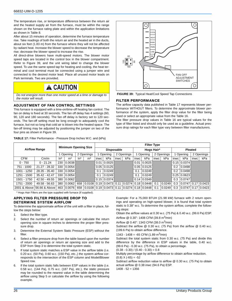
66832-UIM-D-1205
26 Unitary Products Group
The temperature rise, or temperature difference between the return airand the heated supply air from the furnace, must be within the rangeshown on the furnace rating plate and within the application limitationsas shown in Table 8.After about 15 minutes of operation, determine the furnace temperaturerise. Take readings of both the return air and the heated air in the ducts,about six feet (1.83 m) from the furnace where they will not be affectedby radiant heat. Increase the blower speed to decrease the temperaturerise; decrease the blower speed to increase the rise.All direct-drive blowers have multi-speed motors. The blower motorspeed taps are located in the control box in the blower compartment.Refer to Figure 39, and the unit wiring label to change the blowerspeed. To use the same speed tap for heating and cooling, the heat ter-minal and cool terminal must be connected using a jumper wire andconnected to the desired motor lead. Place all unused motor leads onPark terminals. Two are provided.
ADJUSTMENT OF FAN CONTROL SETTINGSThis furnace is equipped with a time-on/time-off heating fan control. Thefan on delay is fixed at 30 seconds. The fan off delay has 4 settings (60,90, 120 and 180 seconds). The fan off delay is factory set to 120 sec-onds. The fan-off setting must be long enough to adequately cool thefurnace, but not so long that cold air is blown into the heated space. Thefan-off timing may be adjusted by positioning the jumper on two of thefour pins as shown in Figure 39.
FILTER PERFORMANCEThe airflow capacity data published in Table 17 represents blower per-formance WITHOUT filters. To determine the approximate blower per-formance of the system, apply the filter drop value for the filter beingused or select an appropriate value from the Table 16.The filter pressure drop values in Table 16 are typical values for thetype of filter listed and should only be used as a guideline. Actual pres-sure drop ratings for each filter type vary between filter manufacturers.
* Hogs Hair Filters are the type supplied with furnace (if supplied).
APPLYING FILTER PRESSURE DROP TO DETERMINE SYSTEM AIRFLOWTo determine the approximate airflow of the unit with a filter in place, fol-low the steps below:1. Select the filter type.2. Select the number of return air openings or calculate the return
opening size in square inches to determine the proper filter pres-sure drop.
3. Determine the External System Static Pressure (ESP) without thefilter.
4. Select a filter pressure drop from the table based upon the numberof return air openings or return air opening size and add to theESP from Step 3 to determine the total system static.
5. If total system static matches a ESP value in the airflow table (i.e.0.20 w.c. (50 Pa), 0.60 w.c. (150 Pa), etc.,) the system airflow cor-responds to the intersection of the ESP column and Model/BlowerSpeed row.
6. If the total system static falls between ESP values in the table (i.e.0.58 w.c. (144 Pa), 0.75 w.c. (187 Pa), etc.), the static pressuremay be rounded to the nearest value in the table determining theairflow using Step 5 or calculate the airflow by using the followingexample.
Example: For a 75,000 BTUH (21.98 kW) furnace with 2 return open-ings and operating on high-speed blower, it is found that total systemstatic is 0.38” w.c. To determine the system airflow, complete the follow-ing steps:Obtain the airflow values at 0.30 w.c. (75 Pa) & 0.40 w.c. (99.6 Pa) ESP.Airflow @ 0.30”: 1408 CFM (39.8 m3/min)Airflow @ 0.40”: 1343 CFM (38.0 m3/min)Subtract the airflow @ 0.30 w.c. (75 Pa) from the airflow @ 0.40 w.c.(199.6 Pa) to obtain airflow difference.1343 - 1408 = -65 CFM (1.89 m3/min)Subtract the total system static from 0.30 w.c. (75 Pa) and divide thisdifference by the difference in ESP values in the table, 0.40 w.c.(99.6 Pa) - 0.30 w.c. (75 Pa), to obtain a percentage.(0.38 - 0.30) / (0.40 - 0.30) = 0.8Multiply percentage by airflow difference to obtain airflow reduction.(0.8) X (-65) = -52Subtract airflow reduction value to airflow @ 0.30 w.c. (75 Pa) to obtainactual airflow @ 0.38 inwc (94.6 Pa) ESP.1408 - 52 = 1356
Do not energize more than one motor speed at a time or damage tothe motor will result.
FIGURE 39: Typical Heat/Cool Speed Tap Connections
60
90
120
180
PARK
PARK
LINE
XM
COOL
HEAT
FAN OFFADJUSTMENTSWITCHES
TABLE 17: Filter Performance - Pressure Drop Inches W.C. and (kPa)
Airflow Range Minimum Opening SizeFilter Type
Disposable Hogs Hair* Pleated 1 Opening 2 Openings 1 Opening 2 Openings 1 Opening 2 Openings 1 Opening 2 Openings
CFM Cm/m In³ m³ In³ m³ inwc kPa inwc kPa inwc kPa inwc kPa inwc kPa inwc kPa0 - 750 0 - 21.24 230 0.0038 0.01 0.0025 0.01 0.0025 0.15 0.0374
751 - 1000 21.27 - 28.32 330 0.0054 0.05 0.0125 0.05 0.0125 0.2 0.04981001 - 1250 28.35 - 35.40 330 0.0054 0.1 0.0249 0.1 0.0249 0.2 0.04981251 - 1500 35.42 - 42.47 330 0.0054 0.1 0.0249 0.1 0.0249 0.25 0.06231501 - 1750 42.50 - 49.55 380 0.0062 0.15 0.0374 0.14 0.0349 0.3 0.07471751 - 2000 49.58 - 56.63 380 0.0062 658 0.0108 0.19 0.0473 0.11 0.0274 0.18 0.0448 0.1 0.0249 0.3 0.0747 0.17 0.0423
2001 & Above 56.66 & Above 463 0.0076 658 0.0108 0.19 0.0473 0.11 0.0274 0.18 0.0448 0.1 0.0249 0.3 0.0747 0.17 0.0423
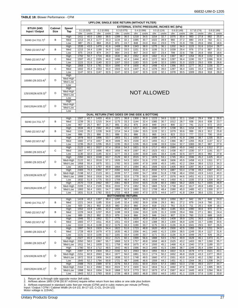
66832-UIM-D-1205
Unitary Products Group 27
Input / Output / CFM / Cabinet Width (A=14-1/2, B=17-1/2, C=21, D=24-1/2)Motor voltage is 115VAC.
TABLE 18: Blower Performance - CFM
UPFLOW, SINGLE SIDE RETURN (WITHOUT FILTER)
BTU/H (kW)Input / Output
Cabinet Size
Speed Tap
EXTERNAL STATIC PRESSURE, INCHES WC (kPa)0.1 (0.025) 0.2 (0.050) 0.3 (0.075) 0.4 (0.099) 0.5 (0.124) 0.6 (0.149) 0.7 (0.174) 0.8 (0.199)
cfm cm/m cfm cm/m cfm cm/m cfm cm/m cfm cm/m cfm cm/m cfm cm/m cfm cm/m
50/40 (14.7/11.7)1 BHigh 1411 40.0 1360 38.5 1289 36.5 1218 34.5 1154 32.7 1075 30.4 983 27.8 882 25.0Med 1213 34.3 1177 33.3 1134 32.1 1085 30.7 1022 28.9 960 27.2 880 24.9 782 22.1Low 887 25.1 884 25.0 871 24.7 848 24.0 814 23.0 775 21.9 726 20.6 656 18.6
75/60 (22.0/17.6)1 BHigh 1535 43.5 1470 41.6 1408 39.9 1343 38.0 1275 36.1 1202 34.0 1115 31.6 1014 28.7Med 1215 34.4 1199 34.0 1182 33.5 1151 32.6 1106 31.3 1039 29.4 976 27.6 887 25.1Low 875 24.8 874 24.7 864 24.5 847 24.0 827 23.4 799 22.6 736 20.8 658 18.6
75/60 (22.0/17.6)1 CHigh 1792 50.7 1724 48.8 1630 46.2 1552 43.9 1462 41.4 1367 38.7 1264 35.8 1152 32.6Med 1597 45.2 1555 44.0 1496 42.4 1444 40.9 1372 38.9 1287 36.4 1190 33.7 1086 30.8Low 1115 31.6 1140 32.3 1167 33.0 1183 33.5 1149 32.5 1093 31.0 1023 29.0 939 26.6
100/80 (29.3/23.4)1 CHigh 1868 52.9 1781 50.4 1690 47.9 1600 45.3 1498 42.4 1396 39.5 1277 36.2 1156 32.7Med 1602 45.4 1553 44.0 1503 42.6 1447 41.0 1376 39.0 1287 36.4 1181 33.4 1060 30.0Low 1147 32.5 1147 32.5 1147 32.5 1147 32.5 1132 32.1 1078 30.5 1009 28.6 918 26.0
100/80 (29.3/23.4)2 D
High
NOT ALLOWED
Med-HighMed-Low
Low
125/100(36.6/29.3)3 D
HighMed-HighMed-Low
Low
150/120(44.0/35.2)2 D
HighMed-HighMed-Low
LowDUAL RETURN (TWO SIDES OR ONE-SIDE & BOTTOM)
50/40 (14.7/11.7)1 BHigh 1507 42.7 1433 40.6 1371 38.8 1300 36.8 1223 34.6 1132 32.1 1040 29.4 938 26.6Med 1239 35.1 1215 34.4 1175 33.3 1144 32.4 1085 30.7 1012 28.7 938 26.6 838 23.7Low 907 25.7 907 25.7 891 25.2 875 24.8 849 24.0 800 22.7 741 21.0 672 19.0
75/60 (22.0/17.6)1 BHigh 1634 46.3 1562 44.2 1484 42.0 1417 40.1 1340 37.9 1238 35.1 1154 32.7 1030 29.2Med 1243 35.2 1228 34.8 1214 34.4 1184 33.5 1133 32.1 1079 30.6 999 28.3 912 25.8Low 886 25.1 886 25.1 886 25.1 886 25.1 865 24.5 823 23.3 777 22.0 700 19.8
75/60 (22.0/17.6)1 CHigh 1978 56.0 1896 53.7 1803 51.1 1693 47.9 1589 45.0 1478 41.9 1366 38.7 1235 35.0Med 1682 47.6 1657 46.9 1606 45.5 1530 43.3 1455 41.2 1366 38.7 1265 35.8 1137 32.2Low 1235 35.0 1235 35.0 1235 35.0 1235 35.0 1198 33.9 1154 32.7 1083 30.7 987 27.9
100/80 (29.3/23.4)1 CHigh 2122 60.1 2027 57.4 1916 54.3 1821 51.6 1717 48.6 1590 45.0 1462 41.4 1312 37.2Med 1667 47.2 1696 48.0 1656 46.9 1597 45.2 1523 43.1 1438 40.7 1330 37.7 1191 33.7Low 1130 32.0 1145 32.4 1177 33.3 1194 33.8 1181 33.4 1146 32.5 1077 30.5 982 27.8
100/80 (29.3/23.4)2 D
High 2350 66.5 2248 63.7 2129 60.3 2015 57.1 1876 53.1 1745 49.4 1596 45.2 1425 40.4Med-High 2122 60.1 2018 57.1 1926 54.5 1824 51.6 1722 48.8 1606 45.5 1458 41.3 1311 37.1Med-Low 1958 55.4 1875 53.1 1782 50.5 1690 47.9 1608 45.5 1491 42.2 1364 38.6 1213 34.3
Low 1820 51.5 1757 49.8 1664 47.1 1594 45.1 1506 42.6 1405 39.8 1287 36.4 1137 32.2
125/100(36.6/29.3)2 D
High 2483 70.3 2392 67.7 2282 64.6 2161 61.2 2032 57.5 1887 53.4 1739 49.2 1567 44.4Med-High 2198 62.2 2123 60.1 2039 57.7 1930 54.7 1830 51.8 1708 48.4 1550 43.9 1413 40.0Med-Low 1999 56.6 1916 54.3 1859 52.6 1778 50.3 1684 47.7 1576 44.6 1451 41.1 1315 37.2
Low 1832 51.9 1775 50.3 1709 48.4 1642 46.5 1556 44.1 1450 41.1 1335 37.8 1209 34.2
150/120(44.0/35.2)2 D
High 2570 72.8 2462 69.7 2361 66.9 2244 63.5 2128 60.3 1983 56.2 1826 51.7 1655 46.9Med-High 2205 62.4 2105 59.6 2033 57.6 1952 55.3 1865 52.8 1738 49.2 1617 45.8 1459 41.3Med-Low 1993 56.4 1931 54.7 1869 52.9 1880 53.2 1708 48.4 1590 45.0 1485 42.1 1330 37.7
Low 1831 51.8 1782 50.5 1722 48.8 1660 47.0 1575 44.6 1477 41.8 1364 38.6 1231 34.9BOTTOM/END RETURN
50/40 (14.7/11.7)1 BHigh 1419 40.2 1357 38.4 1297 36.7 1212 34.3 1131 32.0 1050 29.7 942 26.7 846 24.0Med 1221 34.6 1185 33.6 1145 32.4 1092 30.9 1036 29.3 961 27.2 879 24.9 780 22.1Low 920 26.1 902 25.5 883 25.0 860 24.4 818 23.2 761 21.5 711 20.1 639 18.1
75/60 (22.0/17.6)1 BHigh 1552 43.9 1491 42.2 1420 40.2 1348 38.2 1271 36.0 1185 33.6 1080 30.6 970 27.5Med 1229 34.8 1237 35.0 1198 33.9 1164 33.0 1105 31.3 1039 29.4 956 27.1 861 24.4Low 889 25.2 892 25.3 879 24.9 866 24.5 846 24.0 807 22.9 760 21.5 689 19.5
75/60 (22.0/17.6)1 CHigh 1946 55.1 1862 52.7 1775 50.3 1620 45.9 1518 43.0 1409 39.9 1291 36.6 1160 32.8Med 1683 47.7 1611 45.6 1551 43.9 1484 42.0 1388 39.3 1300 36.8 1190 33.7 1080 30.6Low 1110 31.4 1138 32.2 1175 33.3 1190 33.7 1175 33.3 1126 31.9 1041 29.5 937 26.5
100/80 (29.3/23.4)1 CHigh 1997 56.5 1920 54.4 1822 51.6 1723 48.8 1620 45.9 1500 42.5 1355 38.4 1211 34.3Med 1728 48.9 1679 47.5 1635 46.3 1556 44.1 1465 41.5 1359 38.5 1249 35.4 1117 31.6Low 1131 32.0 1156 32.7 1181 33.4 1190 33.7 1171 33.2 1126 31.9 1049 29.7 926 26.2
100/80 (29.3/23.4)2 D
High 2327 65.9 2232 63.2 2121 60.1 1999 56.6 1888 53.5 1763 49.9 1628 46.1 1473 41.7Med-High 2050 58.0 1967 55.7 1868 52.9 1757 49.8 1658 46.9 1525 43.2 1403 39.7 1260 35.7Med-Low 1911 54.1 1839 52.1 1758 49.8 1675 47.4 1593 45.1 1468 41.6 1340 37.9 1189 33.7
High 1780 50.4 1712 48.5 1642 46.5 1566 44.3 1465 41.5 1366 38.7 1249 35.4 1094 31.0
125/100(36.6/29.3)2 D
High 2397 67.9 2304 65.2 2192 62.1 2063 58.4 1955 55.4 1822 51.6 1678 47.5 1521 43.1Med-High 2151 60.9 2063 58.4 1977 56.0 1881 53.3 1774 50.2 1652 46.8 1528 43.3 1377 39.0Med-Low 1972 55.8 1906 54.0 1838 52.0 1748 49.5 1660 47.0 1551 43.9 1419 40.2 1282 36.3
Low 1845 52.2 1794 50.8 1721 48.7 1646 46.6 1559 44.1 1451 41.1 1344 38.1 1208 34.2
150/120(44.0/35.2)2 D
High 2488 70.5 2389 67.6 2276 64.4 2151 60.9 2024 57.3 1883 53.3 1730 49.0 1577 44.7Med-High 2164 61.3 2084 59.0 2024 57.3 1920 54.4 1816 51.4 1692 47.9 1558 44.1 1395 39.5Med-Low 1998 56.6 1934 54.8 1868 52.9 1773 50.2 1673 47.4 1567 44.4 1445 40.9 1294 36.6
Low 1843 52.2 1793 50.8 1728 48.9 1653 46.8 1553 44.0 1453 41.1 1328 37.6 1192 33.8
1. Return air is through side opposite motor (left side).2. Airflows above 1800 CFM (50.97 m3/min) require either return from two sides or one side plus bottom3. Airflows expressed in standard cubic feet per minute (CFM) and in cubic meters per minute (m3/min).
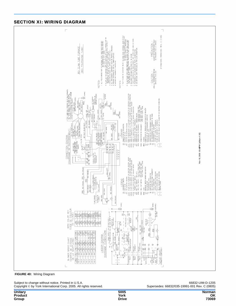
Subject to change without notice. Printed in U.S.A. 66832-UIM-D-1205Copyright © by York International Corp. 2005. All rights reserved. Supersedes: 66832/035-19991-001 Rev. C (0805)
Unitary 5005 NormanProduct York OKGroup Drive 73069
SECTION XI: WIRING DIAGRAM
FIGURE 40: Wiring Diagram
Nov
18,
200
5 0
3:43
PM
[a5
kps
v1.5
0]
�