Embed Size (px)
Citation preview

INSTALLATION MANUAL

Table of Contents
1
Table of Contents
Table of Contents1 General Information ......................................................................................................................................... 2
2 Safety information ............................................................................................................................................ 5
3 Requirements ................................................................................................................................................... 6
4 Installation ........................................................................................................................................................ 74.1 Safety information . . . . . . . . . . . . . . . . . . . . . . . . . . . . . . . . . . . . . . . . . . . . . . . . . . . . . . . . . . . . . . . . . . 74.2 Work steps . . . . . . . . . . . . . . . . . . . . . . . . . . . . . . . . . . . . . . . . . . . . . . . . . . . . . . . . . . . . . . . . . . . . . . . . 74.3 Final checks . . . . . . . . . . . . . . . . . . . . . . . . . . . . . . . . . . . . . . . . . . . . . . . . . . . . . . . . . . . . . . . . . . . . . . 12
5 Operation ........................................................................................................................................................ 14
6 Maintenance ................................................................................................................................................... 18
7 Spare parts ..................................................................................................................................................... 19
Edition 1 Versie 3 (12.2016) 815 010 221 3 (en)
This publication is not subject to any update service.You will find the current version on the internet at http://www.wabco.info/i/313

2
Table of contents General Information
1 General InformationPurpose of the document
This publication applies to employees of workshops for repairing and equipping commercial vehicles.
This publication describes the installation of WABCO OptiFlowTM Tail systems.
Copyright and trademark notice
The content, particularly technical information, descriptions and figures, corresponds to the state current at the time of printing and is subject to change without notice.
This document, including all its parts, in particular texts and figures, is protected by copyright. Use outside the statutory or contractual limits require authorisation by the copyright owner. All rights reserved.
Any brand names, even if not indicated as such, are subject to the rules of the trademark and labelling rights.
Symbols used
WARNING Specifies a potentially hazardous situation Not observing the safety instruction can result in severe injuries or death.
– Follow the instructions in this warning note to avoid injury or death.
CAUTION Specifies a potentially hazardous situation Specifies a possible hazardous situation Not observing the safety instruction can result in minor or moderately severe injuries.
– Follow the instructions in this warning to avoid any injuries.
CAUTION Specifies possible material damageNot observing the safety instruction can lead to material damage.
– Follow the instructions in this warning note to avoid any material damage.
! Important instructions, information, or tips that you should always observe.
Reference to information on the Internet
– Action step
Ö Consequence of an action
� List

3
General Information
Technical documents
– Open the WABCO INFORM online product catalogue: http://inform.wabco-auto.com
– Search for documents by entering the document number.
The WABCO online product catalogue INFORM provides you with convenient access to the complete technical documentation. All documents are available in PDF format. Please contact your WABCO partner for printed versions.
Please note that the publications are not always available in all language versions.
DOCUMENT TITLE DOCUMENT NUMBER
OptiFlowTM Tail – Installation Manual 815 XX0 221 3
*Language code XX: 01 = English, 02 = German, 03 = French, 04 = Spanish, 05 = Italian, 06 = Dutch, 07 = Swedish, 08 = Russian, 09 = Polish, 10 = Croatian, 11 = Romanian, 12 = Hungarian, 13 = Portuguese (Portugal), 14 = Turkish, 15 = Czech, 16 = Chinese, 17 = Korean, 18 = Japanese, 19 = Hebrew, 20 = Greek, 21 = Arabic, 24 = Danish, 25 = Lithuanian, 26 = Norwegian, 27 = Slovenian, 28 = Finnish, 29 = Estonian, 30 = Latvian, 31 = Bulgarian, 32 = Slovakian, 34 = Portuguese (Brazil), 35 = Macedonian, 36 = Albanian, 97 = German/English 98 = = multilingual, 99 = non-verbal
Structure of the WABCO product number
WABCO product numbers consist of 10 digits.
Production date
Type of device Variant Status digit
0 = New device (complete device); 1 = New device (subassembly); 2 = Repair kit or subassembly; 4 = Component part; 7 = Replacement device
Choose genuine WABCO parts
Genuine WABCO parts are made of high quality materials and are rigorously tested before they leave our factories. You also have the assurance that the quality of every WABCO product is supported by a powerful customer service network.As a leading supplier to the industry, WABCO collaborates with the world’s leading original equipment manufacturers, and disposes of the experience and capacitive capability required to also satisfy the most stringent production standards. The quality of every genuine WABCO part is supported by:
� Tooling made for serial production
� Regular sub-supplier audits
� Exhaustive end-of-line tests
� Quality standards < 50 PPM
Installing replica parts can cost lives – genuine WABCO parts protect your business.

4
General Information Safety information
WABCO additional services
The package you will get with a genuine WABCO part:
� 24-month product warranty
� Overnight delivery
� Technical support from WABCO
� Professional training solutions from the WABCO Academy
� Access to diagnostics tools and support from the WABCO Service Partner network
� Straightforward claims handling
� Confidence that the vehicle manufacturer’s rigorous quality standards are met.
WABCO Service Partner
WABCO Service Partners – the network you can rely on. You can access 2000 high quality workshops with more than 6000 specialist mechanics, all trained to WABCO’s exacting standards and equipped with our most up-to-the-minute systems diagnostic and support technology.
Your direct contact to WABCO
In addition to our online services, trained members of staff are there to help you at our WABCO Service Partners to directly answer any technical or business-related questions you may have.
Contact us if you need assistance:
� Find the right product
� Diagnosis support
� Training
� System support
� Order management
You can find your WABCO partner here: http://www.wabco-auto.com/en/how-to-find-us/contact/

5
Safety information
2 Safety informationObserve all required provisions and instructions:
� Read this publication carefully. Adhere to all instructions, information and safety information to prevent injury to persons and damage to property. WABCO will only guarantee the security, reliability and performance of their products and systems if all information in this publication is adhered to.
� Always follow the specifications and instructions of the vehicle manufacturer.
� Observe all accident regulations of the respective company as well as regional and national regulations.
Make provisions for a safe work environment:
� Only trained and qualified technicians are allowed to perform work on the vehicle. OptiFlowTM Tail must be installed by two trained persons.
� Install OptiFlowTM Tail in an enclosed environment.
� Use personal protective equipment if required (protective goggles, respiratory protection, ear protectors, etc.).
� Pedal actuations can lead to severe injuries if persons are in the vicinity of the vehicle. Make sure that pedals cannot be actuated as follows:
� Switch the transmission to "neutral" and actuate the park brake.
� Secure the vehicle against rolling with chocks.
� Fasten a visible note to the steering wheel indicating that work is being performed on the vehicle and that the pedals are not to be actuated.
Observe the following safety instructions when dealing with the OptiFlowTM Tail system to avoid personal injury or damage to components:
� Secure the portal doors against unintended movement.
� Keep the portal doors closed while OptiFlowTM Tail is deployed.
� At wind speeds above 80 km/h fold OptiFlowTM Tail together to avoid damage to the system.
� Fold the OptiFlowTM Tail down while standstill (in accordance with EU regulation 1230/2012). During the winter period snow and ice can accumulate on the top panels and injure the driver when folding down the system.
� Only drive with open portal doors if you do not exceed the legally required total width of 2650 mm (in accordance with EU regulation 1230/2012).
� Never drive into a vehicle washing system with OptiFlowTM Tail deployed, because the system could be damaged.

6
Requirements Installation
3 RequirementsLegal requirements
The following legal requirements need to be taken into account for the installation of OptiFlowTM Tail:
LEGAL REQUIREMENTS CONTENT
96/53/EEC � Weights and dimensions � Maximum permitted trailer height: 4000 mm
1230/2012 EU Requirements relating to the aerodynamic systems at the rear of the O3 and O4 vehicles:
� Foldable system � Extension of the trailer width: 50 mm on each side while driving, total width may not exceed 2650 mm.
� Extension of the trailer length by 500 mm while driving, and during standstill at folded position up to 200 mm.
ECE R 48 Regulations relating to contour marking
Other requirements
! Consult the vehicle manufacturer if the portal doors and hinges of the vehicle are laid-out for an installation of OptiFlowTM Tail with a total weight of 65 kg.
7
Installation
4 Installation
4.1 Safety information � Consult the trailer manufacturer regarding torques. The torques and
connecting elements specified in these instructions are minimum recommendations. If a higher tightening torque is used, the screws / portal doors could be overstrained / damaged.
� Use of additional screws, additional fastening materials or modification of any part of this product is the responsibility of the vehicle manufacturer.
� Always use a soft-face hammer for the installation.
� Prior to installation, ensure that the semitrailer is standing on a horizontal surface so that the body is not in a twisted state. This could influence the panel alignments.
4.2 Work steps
! OptiFlowTM Tail consists of 2x 3 subassembliespage 8. Installation tolerances: +/- 3 mm at a temperature of 18°C.
Install OptiFlowTM Tail in a windless environment – Indoors where appropriate.
OptiFlowTM Tail must be installed by two trained persons.
Preparations
– If external components (e.g. rear view cameras) are already installed, make sure they do not impair the installation and function of the OptiFlowTM Tail system.
– Make sure you have the outline drawing of your Tail variant at hand before you start the installation. If the outline drawing is not available, contact your WABCO partner.
– Check if the dimensions of the outline drawing match the trailer type to be equipped.
– Check the regulations concerning the contour marking and provide the corresponding materials section “Contour marking”, page 13.
– Make sure that all subassemblies required for the installation are included in the delivery.

8
Installation Installation
Subassemblies of the OptiFlowTM Tail system
1
2
3
LEGEND
1 Top panel, left & right 2 Side panel, left & right 3 Lifting rods, left & right

9
Installation
Components of the subassemblies
Com
plet
e ta
il 2
693
±5
Sid
e pa
nel
269
3
499 87
Max
imum
40
00
NOTES:ECOTAIL AS MOUNTED ON A BOX SEMI-TRAILER AT A FIX HEIGHT OF 4000mm
2.0
20-Mar-15
20-Mar-15Luis Ramirez
A0
SHEET 1 OF 2
DWG NO.
TITLE:DATESIGNATURENAME
APPV'D
CHK'D
DRAWN EcoTail General overview - B05Luis C Ramirez
REVISIONDO NOT SCALE DRAWINGDEBUR AND BREAK SHARP EDGES
FINISH:UNLESS OTHERWISE SPECIFIED:DIMENSIONS ARE IN MILLIMETERSSURFACE FINISH:TOLERANCES:LINEAR:ANGULAR:
SCALE:
C:\O
ptfiFlow\EcoTail\D
irectives\
CONFIG TYPE:
TA-1275-00X-B051:10
BOX
C
A
C
B B
B B
A
COMPONENTS OF THE SUBASSEMBLIES
A Levers (2x) B Gas spring (4x) C Fork (2x)
Installation
The assembly steps described below apply to the right and left side of the portal doors.
– Mark the drill positions on the portal doors in accordance with the outline drawing.
! The outside edges of the trailer are the reference edges for the drilling.
– Drill the guide holes using a Ø 4 mm drill bit.
– Expand the hole to Ø 11 mm.

10
Installation Installation
1. Installation of the subassembly for the top panels
– Install the subassembly of the top panels (1) using M10 screws and nuts of at least strength class 8.8. Recommended torque: 25 ±3 Nm
– You may need to tip the top panels (1) slightly.
– After assembly, remove the protective film of the top panels (1).
– Now fit the lifting rods holder using 2 screwssection “Components of the subassemblies”, page 9, in area A.
– Connect the lifting rod (3) to the forksection “Components of the subassemblies”, page 9, in area C.
– Fix the screw (C). Recommended torque: 3 +0.5 Nm.
! Avoid any gap between trailer and sealing lip of the top panels (2).
Correct position of the top panel (side view) Incorrect position of the top panel (side view)
! Make sure that the general trailer dimensions are not exceededchapter "3 Requirements", page 6.
2. Installation of the subassembly for the side panels
– Install the subassembly of the side panels (2) using M10 screws and nuts of at least strength class 8.8. Recommended torque: 25 ±3 Nm
Recommended: Where appropriate use a workshop crane to hold the side panels (2) during installation.
CAUTION Damage to the side panels through workshop crane
– Use retaining straps to avoid damaging the side panels.
! Avoid any gap between trailer and sealing lip of the side panels (2).

11
Installation
Correct position of the side panel (top view) Incorrect position of the side panel (top view)
– Deploy the side panels (2)chapter “5 Operation”, page 14.
3. Installation of the gas springs
WARNING Risk of injury due to pre-tensioned gas springs (B)The gas springs (B) are supplied pre-tensioned and can cause serious injuries if handled incorrectly. – Only remove the cable ties and metal holder from
the gas springs (B) once the gas springs are secured in their holders.
– Connect the gas springs (B) (at the central and bottom door bracket) to the ball heads. The system includes 4 gas springs.
Ö An audible click sound ensures that the gas springs (B) are firmly secured at the bracket.
Example: Installation of the gas springs on the right side panel
Click
– Remove the cable ties and metal holder from the gas springs (B).
– Repeat the above work step for the left side panel.

12
Installation Installation
4.3 Final checks
Mechanics and alignment
Before you drive the vehicle with the OptiFlowTM Tail system, ensure the following:
– All OptiFlowTM Tail components must be firmly secured.
– Check if all mechanisms on the panels function with free movement. Operation of the panels must be possible without restriction.
– Check if each bracket is fastened with the correct torque.
– Check if the panels fit closely on the trailer without a gap when the system is deployed.
– Check if the top panel (1), when folded out, is below the respective side panel (2).
Ö If you have identified a misalignment, align the side panels correctly using the stopper by adjusting the distance to the trailer’s outer edge:
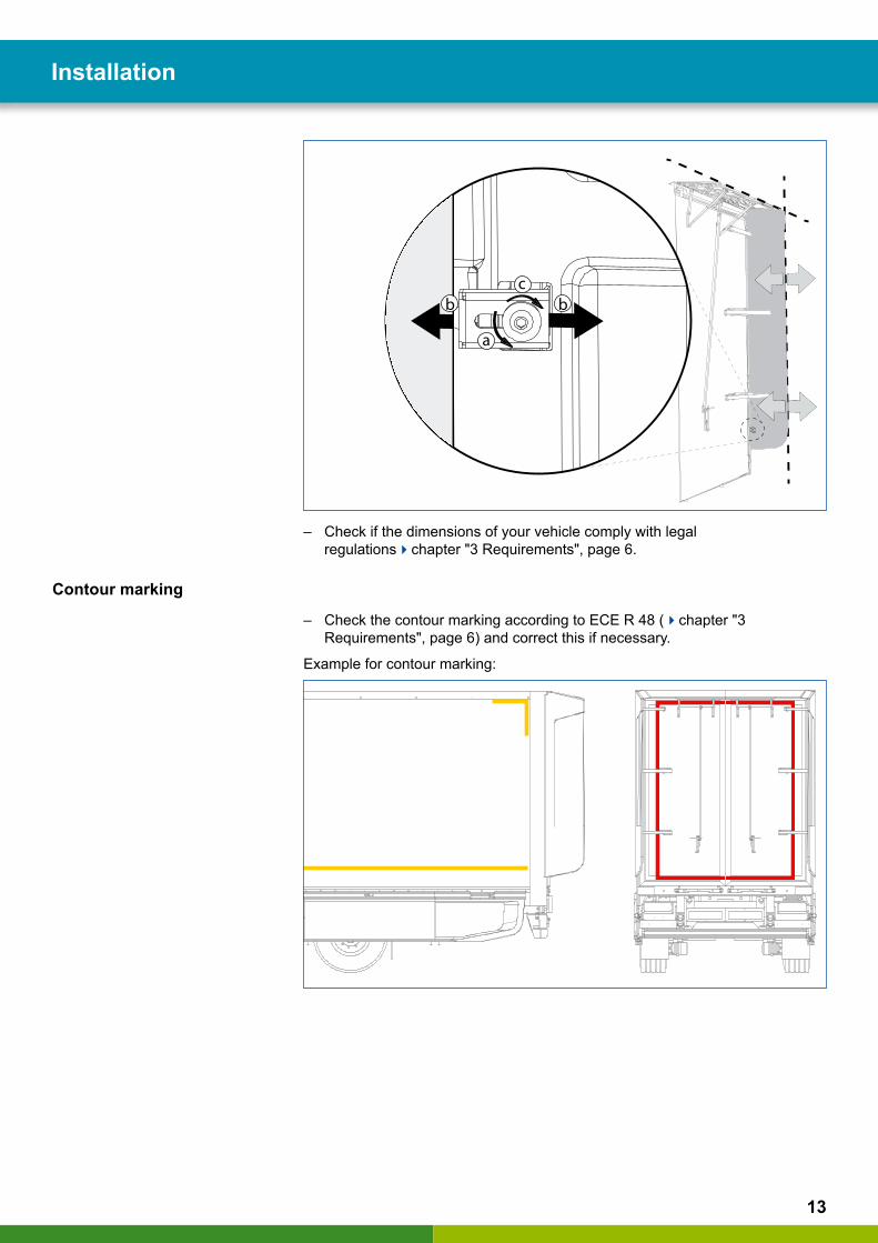
– Unscrew the screw M8 (a).
– Position the stopper (b) so that the top panel is flushing with the side panel, see figure below
– Tighten the screw M8 with 10 +/-2 Nm (c).
13
Installation
cbb
a
– Check if the dimensions of your vehicle comply with legal regulationschapter "3 Requirements", page 6.
Contour marking
– Check the contour marking according to ECE R 48 (chapter "3 Requirements", page 6) and correct this if necessary.
Example for contour marking:
14
Operation Operation
5 Operation
CAUTION Risk of crushing fingers/hands When operating the OptiFlowTM Tail system there is a risk of crushing your fingers/hands.
– When folding out the side panels, make sure that your fingers/hands do not get crushed.
CAUTION Damage to the OptiFlowTM Tail systemThe system could be damaged if your open the por-tal doors while the OptiFlowTM Tail system is folded out.
– Always fold in the panels of the system before you open the portal doors.
Folding out
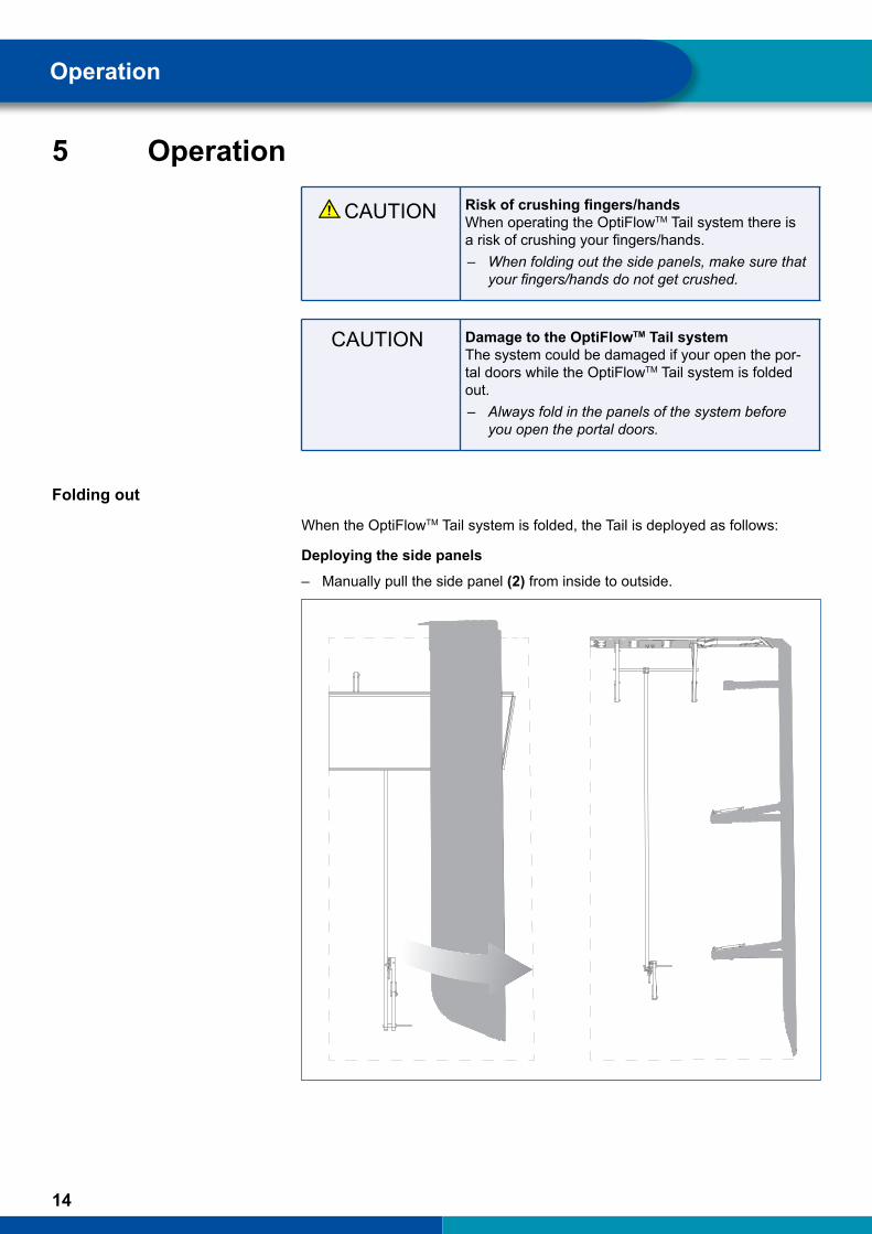
When the OptiFlowTM Tail system is folded, the Tail is deployed as follows:
Deploying the side panels
– Manually pull the side panel (2) from inside to outside.
15
Operation
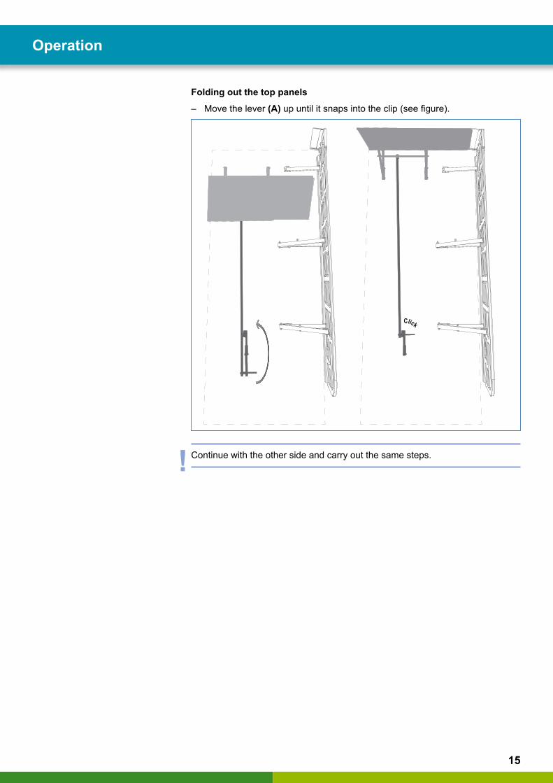
Folding out the top panels
– Move the lever (A) up until it snaps into the clip (see figure).
Click
! Continue with the other side and carry out the same steps.

16
Operation Operation
Folding
CAUTION Damage to the OptiFlowTM Tail systemThe OptiFlowTM Tail system can be damaged if you first fold in the side panels (2).
– Always fold in the top panels (1) first and then the side panels (2).
Folding in the top panel
– Pull the lever (A) out of the holder.
– Move the lever (A) up until the top panel (1) is completely folded.
17
Operation
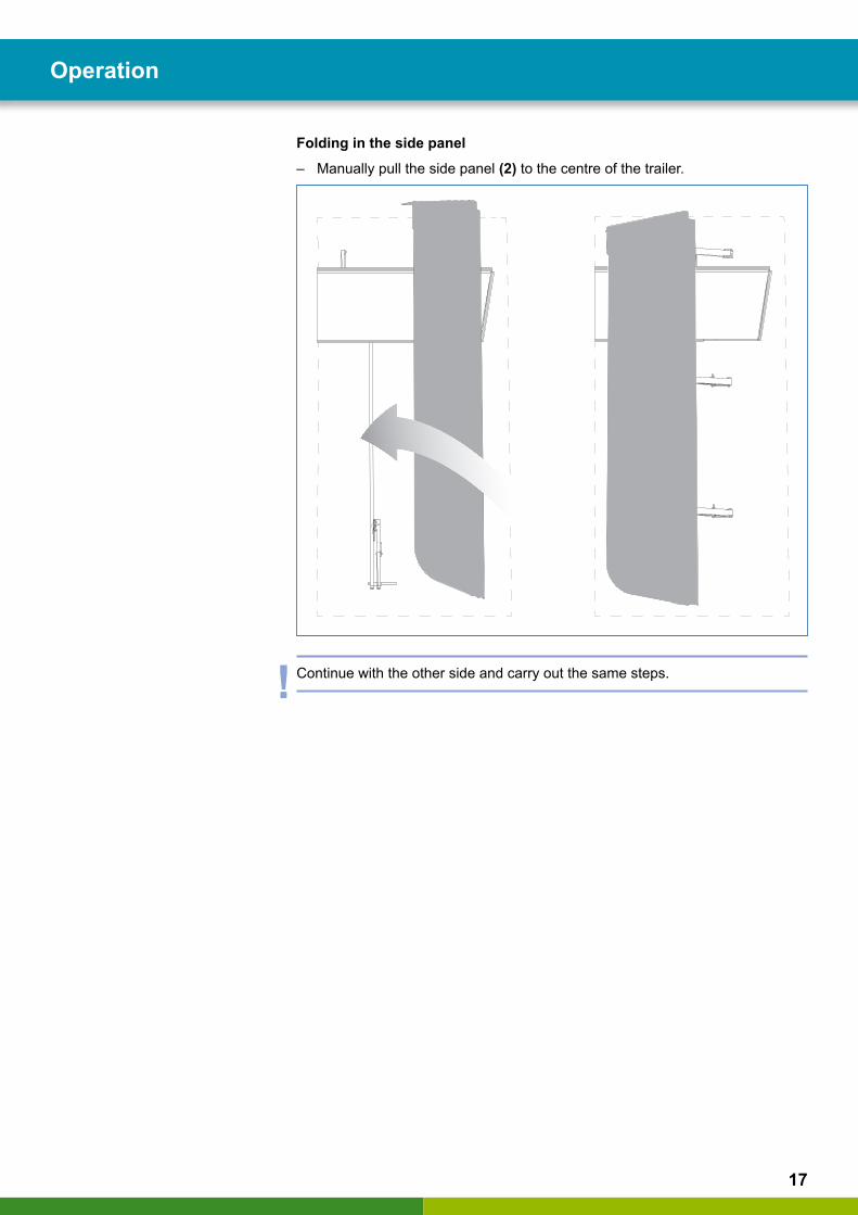
Folding in the side panel
– Manually pull the side panel (2) to the centre of the trailer.
! Continue with the other side and carry out the same steps.

18
Maintenance Spare parts
6 MaintenanceDuring normal operation the OptiFlowTM Tail system must be checked for visible damage.
All maintenance measures are required over the entire service life of the components and should be carried out at 6 month intervals.
Gas springs
– Check the gas springs (B) for ease of movement.
– Check if the panels (2) fit closely on the trailer without a gap.
Lifting rod
– Check the correct function of the top panel (1) by operating the lifting rod via the lever (A). Check the mechanism for ease of movement.
Ö The lifting rod (2) must be connected to the top panel (1) .
Ö If the lever (A) does not engage correctly, the clip lock may need to be replacedchapter “7 Spare parts”, page 19.
– Check if the position of the lifting rods (3) is vertical and the connected crossbar to the top panel (1) is not deformed.
Ö Check the positioning of the door bracket to avoid further damage.
Stopper
– Check the correct alignment of the side panels (2).
Ö The installed side panels (2) must run parallel to the outer edge.
Ö If you have identified a misalignment, align the side panels (2) correctly using the stopper by adjusting the distance to the trailer’s outer edge, section “Mechanics and alignment”, page 12.
Fine adjustment of the stopper:
– Check if the rubber element is attached to the stopper.
– Re-tighten the torque (M8 screw – 10 +/-2 Nm).
! Rust may develop on some components but will not impair the function.

19
Spare parts
7 Spare partsThe table below provides an overview of the most important spare parts at a glance:
PART NUMBER WABCO NAME FIGURE DESCRIPTION
181 010 010 4 Tail Profile Rubber-1 Rubber lip (9 m sufficient for an OptiFlowTM Tail set)
181 020 069 4 Tail Fork-1 Fork (link between the lifting rod and the top panel)
181 020 070 4 Tail Dist Rng Lftg Rod-1 Spacer, lifting rod mechanism, counterpart of the clip lock
181 020 071 4 Tail Lock-1Clip lock
810 511 109 4 Split Pin ISO1234 - 3,2x20
Split pin (for securing the bolt connection to the bracket)
181 020 080 4 Tail Cover of Hdl-1 Handle (cover of the lever)
181 020 081 4 Tail Spacer-1Spacer
181 210 007 2 Tail Prt Gas Spg-1 Gas spring (pre-tensioned and secured for installation)
181 210 008 2 Tail Stopper-1 Stopper (for adjusting the side panel)
181 020 073 4 Tail Sqr Gloss Caps-1 Protection cap (for installation on the lever or lifting rod)

Notes
20


© 2
016
WA
BC
O E
urop
e B
VB
A –
All
right
s re
serv
ed –
815
010
221
3 /
12.2
016towards autonomous driving,
WABCO also uniquely connects trucks, trailers, drivers, cargo, and fleet operators through telematics, as well as advanced fleet management and mobile solutions. WABCO reported sales of $2.6 billion in 2015. Headquartered in Brussels, Belgium, WABCO has 12,000 employees in 39 countries. For more information, visit
www.wabco-auto.com
WABCO (NYSE: WBC) is a leading global supplier of technologies and services that improve the safety, efficiency and connectivity of commercial vehicles. Founded nearly 150 years ago, WABCO continues to pioneer breakthrough innovations for advanced driver assistance, braking, stability control, suspension, transmission automation and aerodynamics. Partnering with the transportation industry as it maps a route