Embed Size (px)
Citation preview
INSTALLATION MANUAL
VEKTOR MAX – INSTALLATION MANUAL
Installation manual PN: VM-IML-US1 Updated in 12/24/2016
he installation of Vektor MAX™ is easy and quick. The system consists in a single unit with all the
electronics embedded, plus a light-bar for guidance and a high gain GPS/GLONASS antenna. All the
cables required for installation are supplied with the system.
Parts of Vektor MAX™:
COMPONENT PART NUMBER
Touch-screen computer VM-HMI-065
External light-bar VK-LBR-MAX
Cable harness ‘A’ VM-CBL-00A
Cable harness ‘B’ VM-CBL-00B
Cable harness ‘C’ VM-CBL-00C
Cable harness ‘D’ VM-CBL-00D
Antenna cable VM-CBL-GPS
GNSS Antenna VK-ANT-000
Circuit breaker 3A (MIL-C-5809) 7277-2-3
Circuit breaker 5A (MIL-C-5809) 7277-2-5
Planning the installation:
Before starting the installation, consider the length of all the cables and the space that will be available.
Have in mind, that the system parts are connected through cables with limited length. It is also important to
analyze the aircraft structure before drilling holes to mount the components or to pass cables. No part can
obstruct the pilot’s line of sight or compromise his vision of the outside world.
ATTENTION: The weight and balance of your aircraft should follow the instructions of the manufacturer of
your aircraft.
Required tools and parts:
Screwdriver with Phillips head if mounting the unit by the M4 screws supplied with the system;
Cable clamps and components for proper mounting of the cables.
Features needed to be available in the aircraft:
One switch available in the control grip for “Enter” function.
One switch in the by-pass valve’s handle or other device to trigger the spray ON/OFF event.
T
VEKTOR MAX – INSTALLATION MANUAL
Installation manual PN: VM-IML-US1 Updated in 12/24/2016
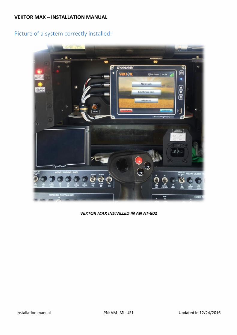
Picture of a system correctly installed:
VEKTOR MAX INSTALLED IN AN AT-802
VEKTOR MAX – INSTALLATION MANUAL
Installation manual PN: VM-IML-US1 Updated in 12/24/2016
General consideration: (Failure to follow these guidelines will void your equipment's warranty)
Disconnect the power before installing the equipment. Do not connect or disconnect cables while the
equipment is powered. Do not force the cables, and do not use tools to tighten the connectors. Do not
expose parts to high temperatures. Never attach a component near any heat exchanger.
Installation sequence:
The following, is the recommended installation sequence and steps:
1. Recognition of each component;
2. Identifying the cables;
3. Vektor MAX™ display unit review;
4. Installing the display in the aircraft’s dashboard;
5. Installing the light-bar;
6. Installing the GNSS antenna;
7. Installing cable harness A;
8. Installing cable harness B;
9. Installing cable harness C;
10. Installing cable harness D;
a. Note: This cable is sent in the acquisition of the valve and flowmeter.
11. GNSS antenna cable;
12. Electrical power considerations;
13. General care and use of the system;
14. Information for certification.
In the following pages, the sequence proposed above is conducted in a very explanatory and illustrated
way.
VEKTOR MAX – INSTALLATION MANUAL
Installation manual PN: VM-IML-US1 Updated in 12/24/2016
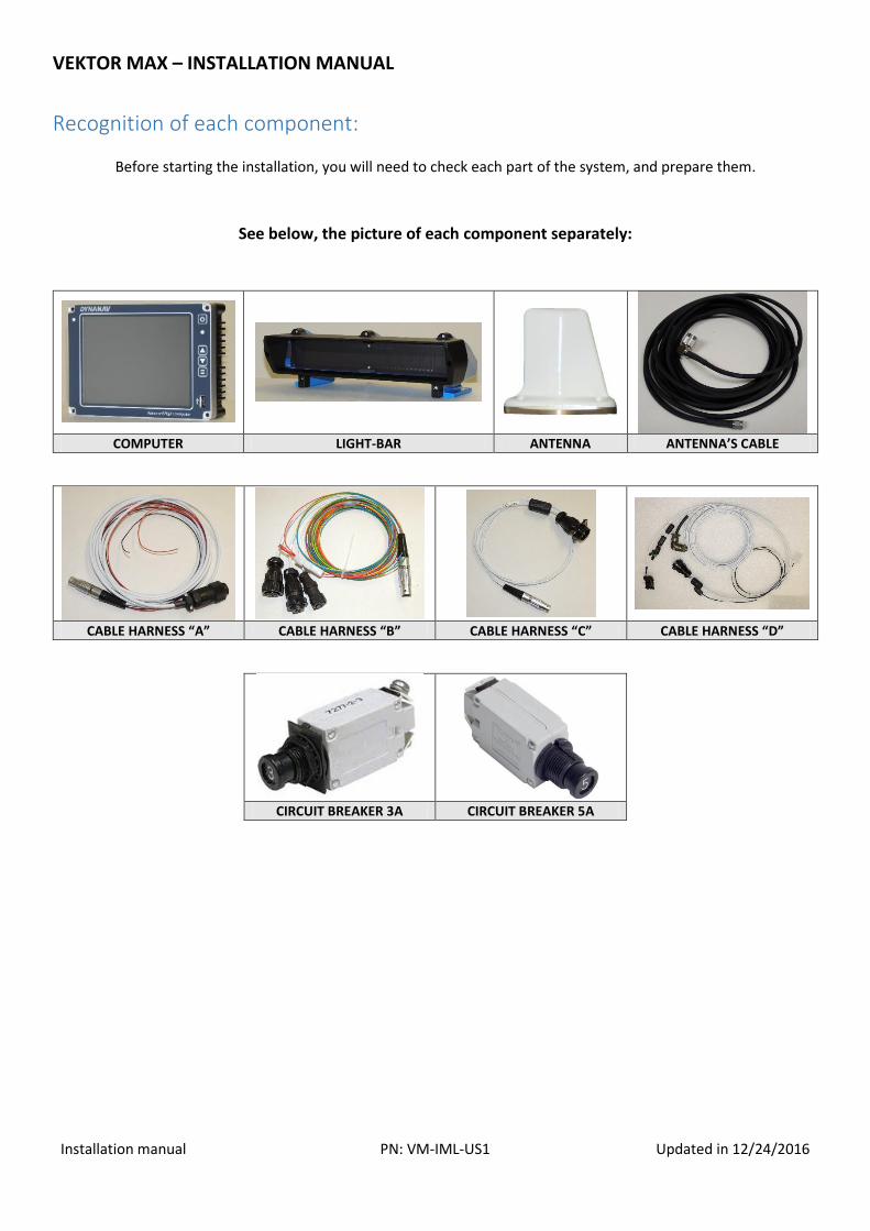
Recognition of each component:
Before starting the installation, you will need to check each part of the system, and prepare them.
See below, the picture of each component separately:
COMPUTER LIGHT-BAR ANTENNA ANTENNA’S CABLE
CABLE HARNESS “A” CABLE HARNESS “B” CABLE HARNESS “C” CABLE HARNESS “D”
CIRCUIT BREAKER 3A CIRCUIT BREAKER 5A
VEKTOR MAX – INSTALLATION MANUAL
Installation manual PN: VM-IML-US1 Updated in 12/24/2016
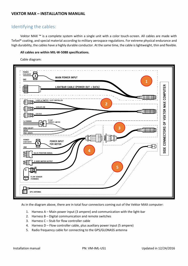
Identifying the cables:
Vektor MAX ™ is a complete system within a single unit with a color touch-screen. All cables are made with
Tefzel® coating, and special material according to military aerospace regulations. For extreme physical endurance and
high durability, the cables have a highly durable conductor. At the same time, the cable is lightweight, thin and flexible.
All cables are within MIL-W-5088 specifications.
Cable diagram:
As in the diagram above, there are in total four connectors coming out of the Vektor MAX computer:
1. Harness A – Main power input (3 ampere) and communication with the light-bar
2. Harness B – Digital communication and remote switches
3. Harness C – Stub for flow controller cable
4. Harness D – Flow controller cable, plus auxiliary power input (5 ampere)
5. Radio frequency cable for connecting to the GPS/GLONASS antenna
1
2
3
4
5

VEKTOR MAX – INSTALLATION MANUAL
Installation manual PN: VM-IML-US1 Updated in 12/24/2016
Vektor MAX™ display unit review
The Vektor MAX computer and display is a rugged unit with all the electronic circuits inside. When mounting the unit
to the aircraft, a few important details must be considered:
Front mounting holes for long screws;
Rear mounting holes with M4 threads in VESA 100 standard;
Position and dimensions of the side connectors for cable harnesses;
Front USB port for data exchange with flash drives;
Front keypad control for brightness adjust and power control;
Memory card slot in the bottom of the device for quick data swap.
Note the details pointed in the images below:
Memory card slot
Side connectors
for cables
ON/OFF, and
brightness
control.
Front USB
WiFi antenna
Telemetry
antenna
Connector A
Connector B
Connector C
Dual display
connection
GNSS Antenna
SMA Connector
Rear mounting holes
with four M4 screws
In VESA 100 standard.
VEKTOR MAX – INSTALLATION MANUAL
Installation manual PN: VM-IML-US1 Updated in 12/24/2016
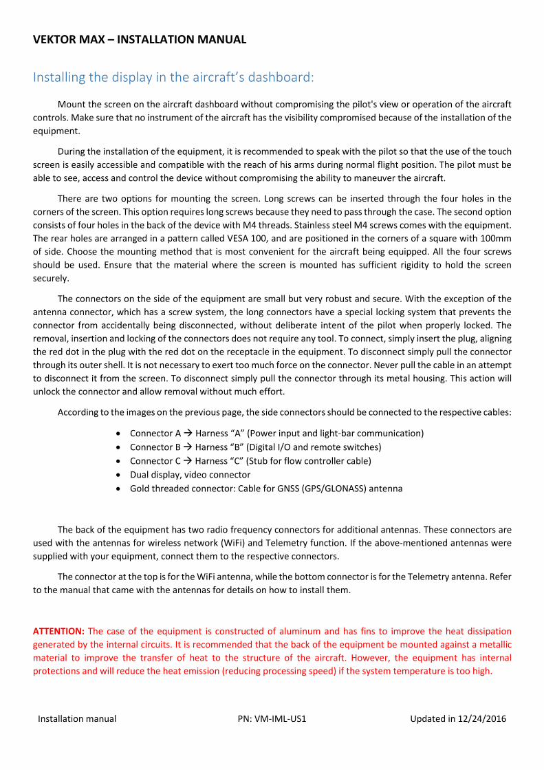
Installing the display in the aircraft’s dashboard:
Mount the screen on the aircraft dashboard without compromising the pilot's view or operation of the aircraft
controls. Make sure that no instrument of the aircraft has the visibility compromised because of the installation of the
equipment.
During the installation of the equipment, it is recommended to speak with the pilot so that the use of the touch
screen is easily accessible and compatible with the reach of his arms during normal flight position. The pilot must be
able to see, access and control the device without compromising the ability to maneuver the aircraft.
There are two options for mounting the screen. Long screws can be inserted through the four holes in the
corners of the screen. This option requires long screws because they need to pass through the case. The second option
consists of four holes in the back of the device with M4 threads. Stainless steel M4 screws comes with the equipment.
The rear holes are arranged in a pattern called VESA 100, and are positioned in the corners of a square with 100mm
of side. Choose the mounting method that is most convenient for the aircraft being equipped. All the four screws
should be used. Ensure that the material where the screen is mounted has sufficient rigidity to hold the screen
securely.
The connectors on the side of the equipment are small but very robust and secure. With the exception of the
antenna connector, which has a screw system, the long connectors have a special locking system that prevents the
connector from accidentally being disconnected, without deliberate intent of the pilot when properly locked. The
removal, insertion and locking of the connectors does not require any tool. To connect, simply insert the plug, aligning
the red dot in the plug with the red dot on the receptacle in the equipment. To disconnect simply pull the connector
through its outer shell. It is not necessary to exert too much force on the connector. Never pull the cable in an attempt
to disconnect it from the screen. To disconnect simply pull the connector through its metal housing. This action will
unlock the connector and allow removal without much effort.
According to the images on the previous page, the side connectors should be connected to the respective cables:
Connector A Harness “A” (Power input and light-bar communication)
Connector B Harness “B” (Digital I/O and remote switches)
Connector C Harness “C” (Stub for flow controller cable)
Dual display, video connector
Gold threaded connector: Cable for GNSS (GPS/GLONASS) antenna
The back of the equipment has two radio frequency connectors for additional antennas. These connectors are
used with the antennas for wireless network (WiFi) and Telemetry function. If the above-mentioned antennas were
supplied with your equipment, connect them to the respective connectors.
The connector at the top is for the WiFi antenna, while the bottom connector is for the Telemetry antenna. Refer
to the manual that came with the antennas for details on how to install them.
ATTENTION: The case of the equipment is constructed of aluminum and has fins to improve the heat dissipation
generated by the internal circuits. It is recommended that the back of the equipment be mounted against a metallic
material to improve the transfer of heat to the structure of the aircraft. However, the equipment has internal
protections and will reduce the heat emission (reducing processing speed) if the system temperature is too high.
VEKTOR MAX – INSTALLATION MANUAL
Installation manual PN: VM-IML-US1 Updated in 12/24/2016
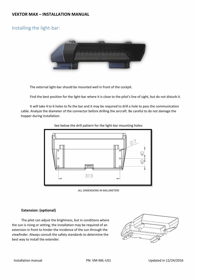
Installing the light-bar:
The external light-bar should be mounted well in front of the cockpit.
Find the best position for the light-bar where it is close to the pilot's line of sight, but do not disturb it.
It will take 4 to 6 holes to fix the bar and it may be required to drill a hole to pass the communication
cable. Analyze the diameter of the connector before drilling the aircraft. Be careful to do not damage the
hopper during installation.
See below the drill pattern for the light-bar mounting holes:
ALL DIMENSIONS IN MILLIMETERS
Extension: (optional)
The pilot can adjust the brightness, but in conditions where
the sun is rising or setting, the installation may be required of an
extension in front to hinder the incidence of the sun through the
viewfinder. Always consult the safety standards to determine the
best way to install the extender.
VEKTOR MAX – INSTALLATION MANUAL
Installation manual PN: VM-IML-US1 Updated in 12/24/2016
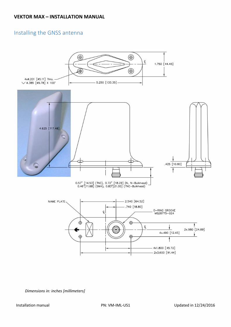
Installing the GNSS antenna
Dimensions in: inches [millimeters]
VEKTOR MAX – INSTALLATION MANUAL
Installation manual PN: VM-IML-US1 Updated in 12/24/2016
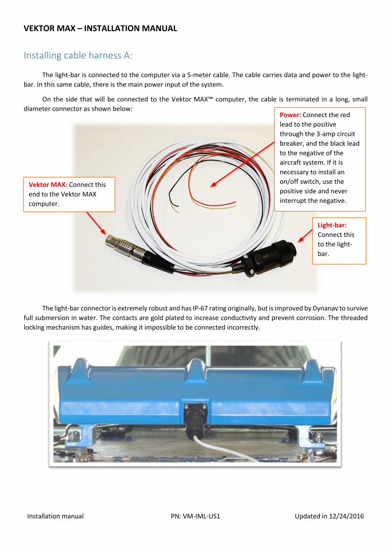
Installing cable harness A:
The light-bar is connected to the computer via a 5-meter cable. The cable carries data and power to the light-
bar. In this same cable, there is the main power input of the system.
On the side that will be connected to the Vektor MAX™ computer, the cable is terminated in a long, small
diameter connector as shown below:
The light-bar connector is extremely robust and has IP-67 rating originally, but is improved by Dynanav to survive
full submersion in water. The contacts are gold plated to increase conductivity and prevent corrosion. The threaded
locking mechanism has guides, making it impossible to be connected incorrectly.
Power: Connect the red
lead to the positive
through the 3-amp circuit
breaker, and the black lead
to the negative of the
aircraft system. If it is
necessary to install an
on/off switch, use the
positive side and never
interrupt the negative.
Vektor MAX: Connect this
end to the Vektor MAX
computer.
Light-bar:
Connect this
to the light-
bar.
VEKTOR MAX – INSTALLATION MANUAL
Installation manual PN: VM-IML-US1 Updated in 12/24/2016
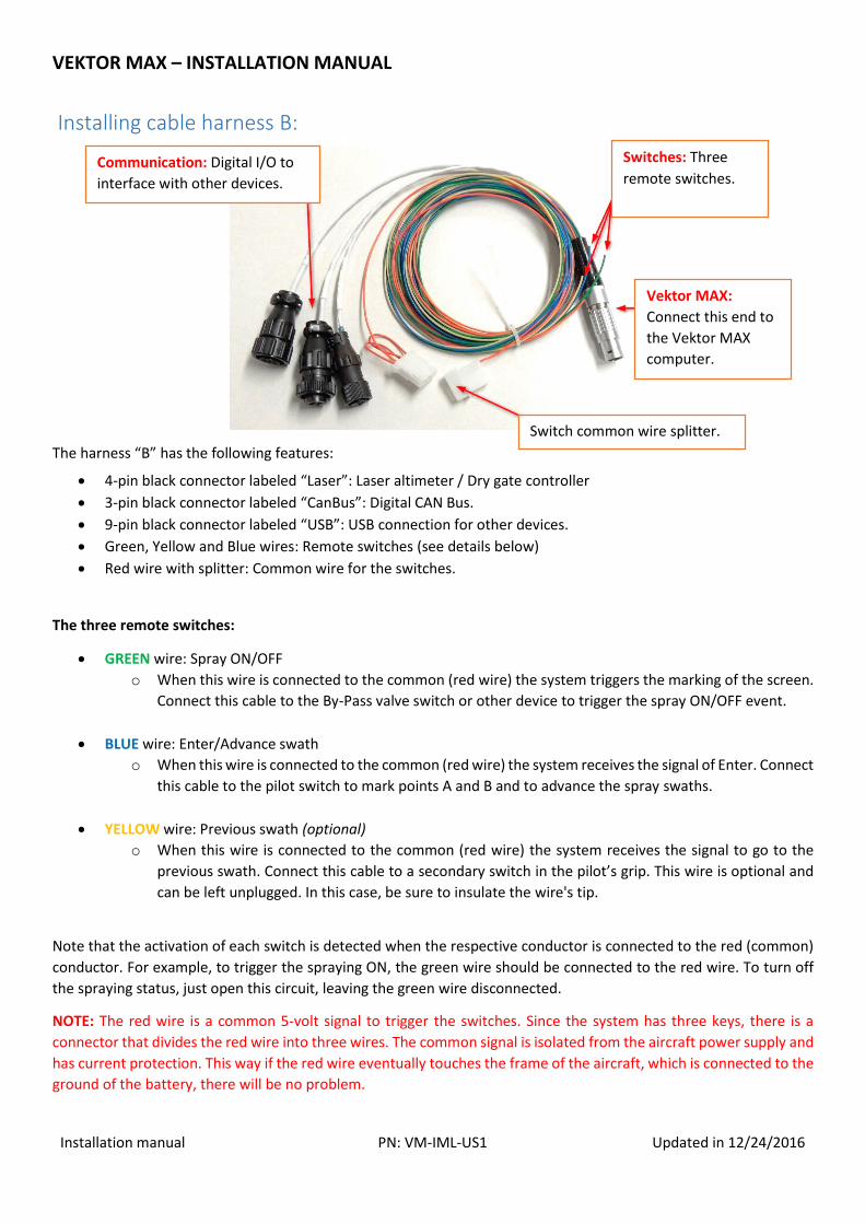
Installing cable harness B:
The harness “B” has the following features:
4-pin black connector labeled “Laser”: Laser altimeter / Dry gate controller
3-pin black connector labeled “CanBus”: Digital CAN Bus.
9-pin black connector labeled “USB”: USB connection for other devices.
Green, Yellow and Blue wires: Remote switches (see details below)
Red wire with splitter: Common wire for the switches.
The three remote switches:
GREEN wire: Spray ON/OFF
o When this wire is connected to the common (red wire) the system triggers the marking of the screen.
Connect this cable to the By-Pass valve switch or other device to trigger the spray ON/OFF event.
BLUE wire: Enter/Advance swath
o When this wire is connected to the common (red wire) the system receives the signal of Enter. Connect
this cable to the pilot switch to mark points A and B and to advance the spray swaths.
YELLOW wire: Previous swath (optional)
o When this wire is connected to the common (red wire) the system receives the signal to go to the
previous swath. Connect this cable to a secondary switch in the pilot’s grip. This wire is optional and
can be left unplugged. In this case, be sure to insulate the wire's tip.
Note that the activation of each switch is detected when the respective conductor is connected to the red (common)
conductor. For example, to trigger the spraying ON, the green wire should be connected to the red wire. To turn off
the spraying status, just open this circuit, leaving the green wire disconnected.
NOTE: The red wire is a common 5-volt signal to trigger the switches. Since the system has three keys, there is a
connector that divides the red wire into three wires. The common signal is isolated from the aircraft power supply and
has current protection. This way if the red wire eventually touches the frame of the aircraft, which is connected to the
ground of the battery, there will be no problem.
Switch common wire splitter.
Switches: Three
remote switches.
Vektor MAX:
Connect this end to
the Vektor MAX
computer.
Communication: Digital I/O to
interface with other devices.
VEKTOR MAX – INSTALLATION MANUAL
Installation manual PN: VM-IML-US1 Updated in 12/24/2016
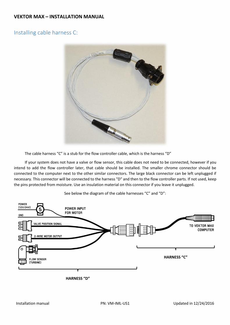
Installing cable harness C:
The cable harness “C” is a stub for the flow controller cable, which is the harness “D”
If your system does not have a valve or flow sensor, this cable does not need to be connected, however if you
intend to add the flow controller later, that cable should be installed. The smaller chrome connector should be
connected to the computer next to the other similar connectors. The large black connector can be left unplugged if
necessary. This connector will be connected to the harness "D" and then to the flow controller parts. If not used, keep
the pins protected from moisture. Use an insulation material on this connector if you leave it unplugged.
See below the diagram of the cable harnesses “C” and “D”:
HARNESS “C”
HARNESS “D”
VEKTOR MAX – INSTALLATION MANUAL
Installation manual PN: VM-IML-US1 Updated in 12/24/2016
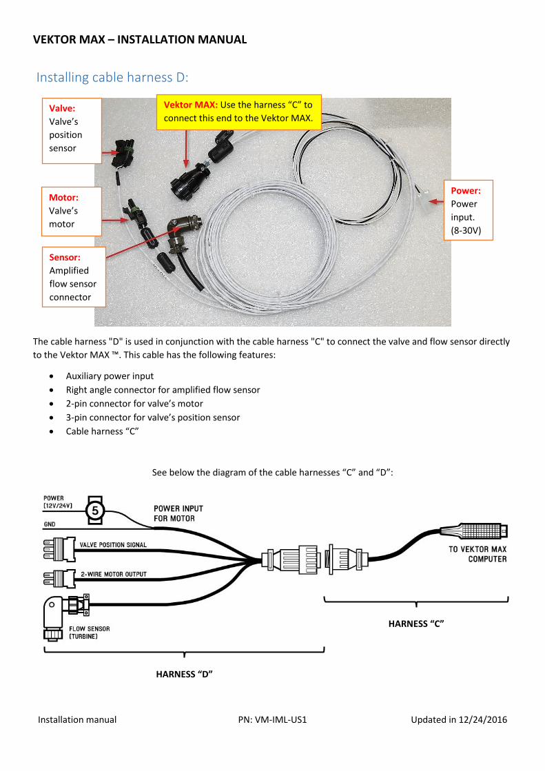
Installing cable harness D:
The cable harness "D" is used in conjunction with the cable harness "C" to connect the valve and flow sensor directly
to the Vektor MAX ™. This cable has the following features:
Auxiliary power input
Right angle connector for amplified flow sensor
2-pin connector for valve’s motor
3-pin connector for valve’s position sensor
Cable harness “C”
See below the diagram of the cable harnesses “C” and “D”:
Valve:
Valve’s
position
sensor
Motor:
Valve’s
motor
Sensor:
Amplified
flow sensor
connector
Vektor MAX: Use the harness “C” to
connect this end to the Vektor MAX.
Power:
Power
input.
(8-30V)
HARNESS “C”
HARNESS “D”
VEKTOR MAX – INSTALLATION MANUAL
Installation manual PN: VM-IML-US1 Updated in 12/24/2016
GNSS antenna cable:
The antenna supplied with Vektor MAX™, is compatible with GPS and GLONASS systems.
The supplied antenna has an internal low noise amplifier inside of it and uses a TNC 50Ohm connector.
The cable has military specifications with SMA and TNC connectors.
The cable must be fixed inside the aircraft and must never be cut, amended or modified.
Keep the threaded connectors properly locked at both ends of the cable.
Do not apply too much tension on the cable, and never crush the cable.
Do not bend the cable in a small angle to avoid damaging the material inside the cable.
Do not pass the cable near circuits or devices that radiate intense electromagnetic field, such as motors or high-
power solenoids.
The antenna cable should be replaced in the presence of any of the following changes:
Corrosion in the connectors;
Cable bent or with some fold that does not return to normal when stretched without much force;
Cable with visible signal of crushing;
Rips in the cable;
Visible change in diameter on a cable segment that indicates damage.
VEKTOR MAX – INSTALLATION MANUAL
Installation manual PN: VM-IML-US1 Updated in 12/24/2016
Electrical power considerations:
The Vektor MAX™ system can be powered in the range of 8 to 30 Volts DC and is therefore suitable for aircraft
with 12Volts or 24Volts systems.
When used in conjunction with flow controller, the system has an extra power input, in addition to the
computer’s main power input. The main and auxiliary power for the flow controller must be independently installed
and should only be merged on the aircraft bus or in a high current power outlet. If this separation is not respected,
when the valve motor moves, the voltage transient in the cables may restart the computer.
Main power: The system main power is made through a red and a black wire, with the function of positive and
negative respectively. The system features protection against interference, transients, and reverse polarity. When the
system is powered on with reverse polarity, the system will not operate and will not be damaged. This cable must pass
through a 3-ampere fuse or circuit breaker.
Flow controller power: The power for the flow controller is through a white and black color cables with the
positive and negative function respectively. This input also has reverse polarity and transient protection. This cable
must pass through a 5-ampere fuse or circuit breaker.
Other considerations:
For greater safety, greater stability and longer life span, avoid connecting the system's power cable together
the cable of high-power relays, solenoids, or equipment that generate a reverse electromotive force voltage, also
called an electromotive force. This type of voltage is generated mainly by equipment that works with electromagnetic
field such as the brake used in the pumps or electric motors. These devices temporarily generate negative voltage at
their power terminals and can destroy sensitive electronic systems. These devices also insert electrical noise in the
power supply line that can affect the operation of electronic systems connected in the same node.
When using a switch to turn the system on/off, install the switch between the circuit breaker and the Vektor
MAX™. The On/Off switch should interrupt the positive terminal, never the negative terminal.
If it is necessary to extend the length of the power cable, use higher gauge conductors than the original cable.
Avoid a length of more than 5 meters in total, up to the main power bus or battery of the aircraft. When there is a
need for a cable longer than 5 meters, contact the manufacturer for more information on the proper cable to be used,
or consult an electrical engineer trained for the aerospace industry.
VEKTOR MAX – INSTALLATION MANUAL
Installation manual PN: VM-IML-US1 Updated in 12/24/2016
General care and use of the system:
TOUCH-SCREEN DISPLAY:
The touch-screen display should be cleaned regularly to avoid scratches and wearing of the material.
Do not use abrasive materials to clean the touch-panel.
Avoid exposing the device directly to the sun light for a long period.
Never use sharp objects such as pens or nails to press the panel.
The touch-screen is able to work even if the pilot is wearing gloves.
Avoid excessive pressure over the panel. Press the screen with a gentle touch.
ELETRICAL SYSTEM:
Make sure your alternator is in good shape to operate, otherwise the system may be damaged.
Check the battery charge. Voltage below the rated voltage of the battery indicates a problem.
If the battery is discharged, or if there is a problem between the plates, the system may not work;
If an on/off switch is installed, use a new, robust switch of at least 10A.
GNSS ANTENNA:
Make sure that the antenna maintains a distance of at least 1 meter (±3 feet) from other antennas.
Install the antenna in a suitable location for greater signal availability.
Never paint over the antenna, or cover it with other material.
VEKTOR MAX – INSTALLATION MANUAL
Installation manual PN: VM-IML-US1 Updated in 12/24/2016
Information for certification:
Make sure that the installed system will meet the following criteria:
Does not block the view or the access to any aircraft flight instrument;
Does not compromise the ability to maneuver the aircraft;
Does not block the pilot’s line of sight to the outside of the cockpit;
Does not block emergency exits or handles;
It is used only for VFR;
It is considered non-essential for flight.
Operation of this equipment must not cause interference to other aircraft systems, nor should other systems or the
switching of electrical power supplies interfere with it.
Make sure that after installation of this equipment, the total electric consumption of the aircraft remains less than or
equal to 80% (eighty percent) of the total electric generation capacity of the same.
The installation of the flow control valve and the flow sensors of the Vektor MAX™ must not adversely affect any other
equipment previously installed.
All components of the system shall be rigidly attached to steel or fire rated plywood construction mounts with
thicknesses of at least 1mm (0.040 in) and 5mm (0.200 in) respectively.
All cables used in this equipment are within MIL-W-5088 specifications. The cables that make up the Vektor MAX™ are
M22759/16 or M27500 with shield.
The equipment comes with 3-amp and 5-amp circuit breaker. These circuit breakers meet the MIL-C-5809
specification. An equivalent or a fuse that meets the MIL-F-15160 specification may replace the original circuit breaker
if has the same current rating and specifications.
No component of this system weighs more than 5 kg individually.
Weight of the main components:
Screen/Computer: Approximately 1Kg (2.2 lbs)
Light-bar: Approximately 3.6 Kg (7.9 lbs)
GNSS antenna: Approximately 0.1 Kg (0.2 lbs)
VEKTOR MAX – INSTALLATION MANUAL
Installation manual PN: VM-IML-US1 Updated in 12/24/2016
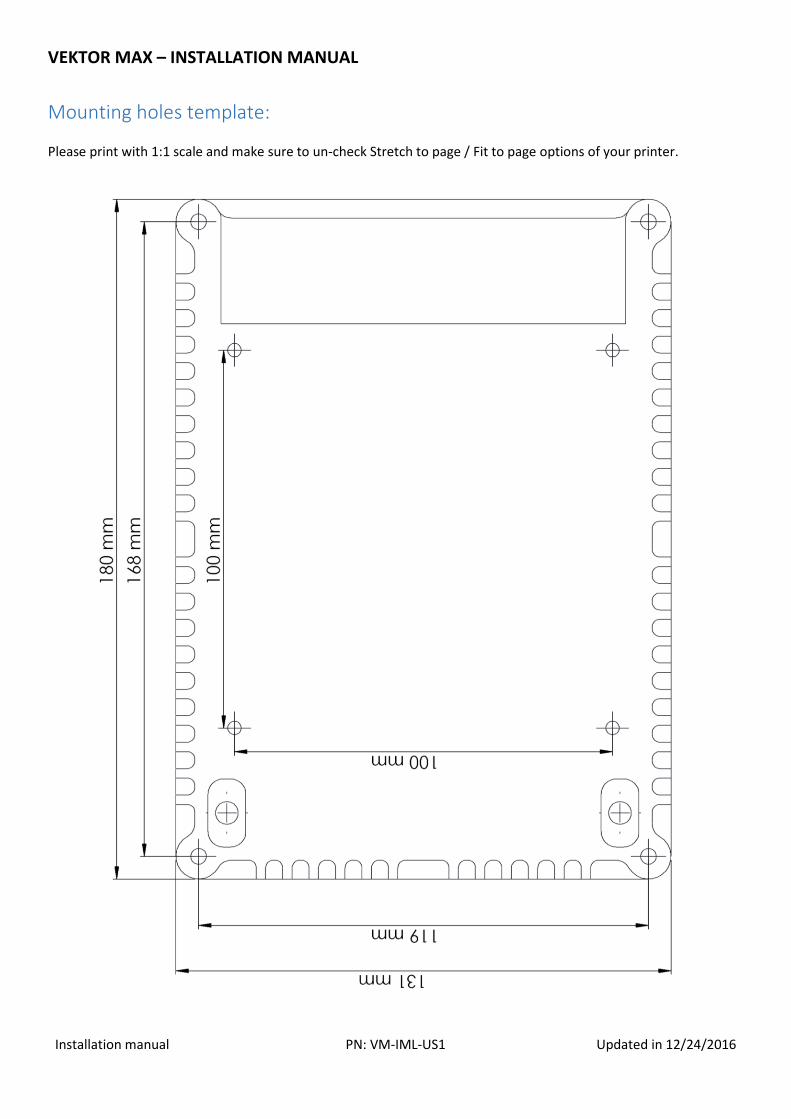
Mounting holes template:
Please print with 1:1 scale and make sure to un-check Stretch to page / Fit to page options of your printer.


![11. CABLE/HARNESS ROUTING - Honda...2-66 11.CABLE/HARNESS ROUTING [6] HARNESS BAND CLIP [4] IAT (INTAKE AIR TEMPERATURE) SENSOR [3] MAP (MANIFOLD ABSOLUTE PRESSURE) SENSOR [5] …](https://img.pdfslide.net/doc/110x75/6128ea67544a0219773ceb3e/11-cableharness-routing-honda-2-66-11cableharness-routing-6-harness.jpg)