Embed Size (px)
Citation preview
Page 1 of 13
Installation Manual: Nissan RoguePower Lift Gate System
Nissan Rogue
NOTE: Not for Rogue Sport Models
Page 2 of 13
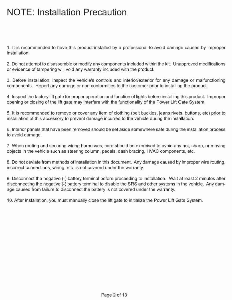
NOTE: Installation Precaution
1. It is recommended to have this product installed by a professional to avoid damage caused by improper installation.
2. Do not attempt to disassemble or modify any components included within the kit. Unapproved modifications or evidence of tampering will void any warranty included with the product.
3. Before installation, inspect the vehicle's controls and interior/exterior for any damage or malfunctioning components. Report any damage or non conformities to the customer prior to installing the product.
4. Inspect the factory lift gate for proper operation and function of lights before installing this product. Improper opening or closing of the lift gate may interfere with the functionality of the Power Lift Gate System.
5. It is recommended to remove or cover any item of clothing (belt buckles, jeans rivets, buttons, etc) prior to installation of this accessory to prevent damage incurred to the vehicle during the installation.
6. Interior panels that have been removed should be set aside somewhere safe during the installation process to avoid damage.
7. When routing and securing wiring harnesses, care should be exercised to avoid any hot, sharp, or moving objects in the vehicle such as steering column, pedals, dash bracing, HVAC components, etc.
8. Do not deviate from methods of installation in this document. Any damage caused by improper wire routing, incorrect connections, wiring, etc. is not covered under the warranty.
9. Disconnect the negative (-) battery terminal before proceeding to installation. Wait at least 2 minutes after disconnecting the negative (-) battery terminal to disable the SRS and other systems in the vehicle. Any dam-age caused from failure to disconnect the battery is not covered under the warranty.
10. After installation, you must manually close the lift gate to initialize the Power Lift Gate System.
Page 3 of 13
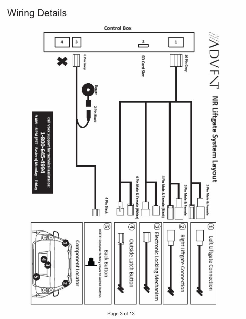
Wiring Details
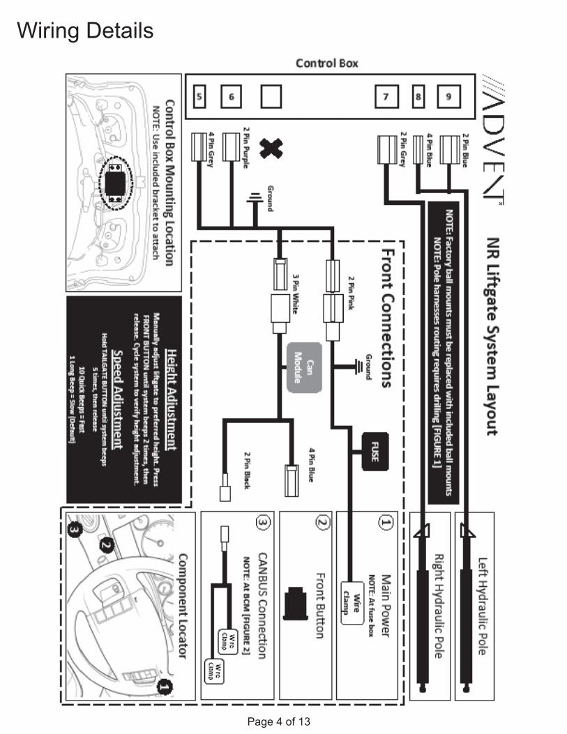
Page 4 of 13
Wiring Details
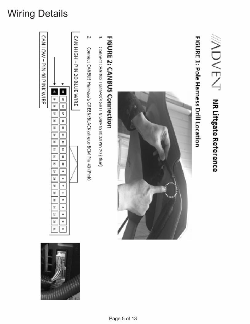
Page 5 of 13
Wiring Details
Page 6 of 13
INSTALLATION PREPARATION
Before starting installation
1. Familiarize yourself with the installation instructions.
2. Inspect kit components to verify everything is pres-ent, there is no damage, and to familiarize yourself with the parts.
Negative Battery Cable
INSTALLATION:
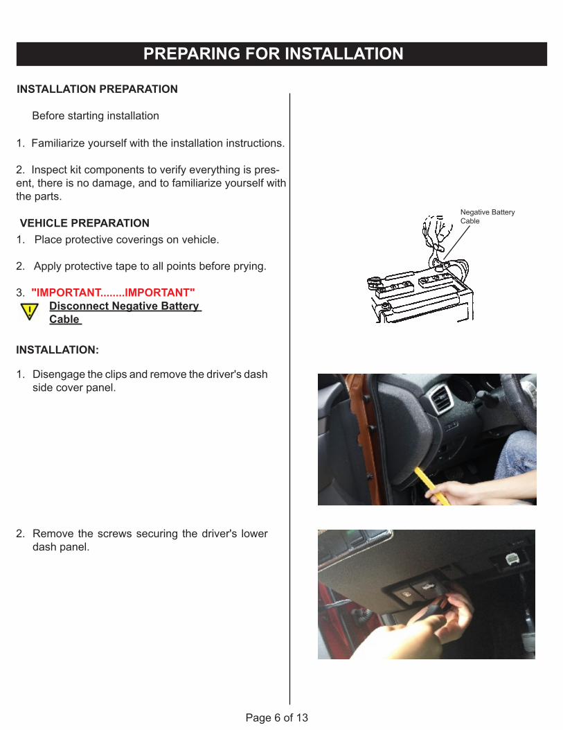
1. Disengage the clips and remove the driver's dash side cover panel.
2. Remove the screws securing the driver's lower dash panel.
PREPARING FOR INSTALLATION
VEHICLE PREPARATION1. Place protective coverings on vehicle.
2. Apply protective tape to all points before prying.
3. "IMPORTANT........IMPORTANT" Disconnect Negative Battery Cable
Page 7 of 13
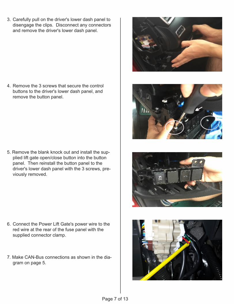
3. Carefully pull on the driver's lower dash panel to disengage the clips. Disconnect any connectors and remove the driver's lower dash panel.
4. Remove the 3 screws that secure the control buttons to the driver's lower dash panel, and remove the button panel.
5. Remove the blank knock out and install the sup-plied lift gate open/close button into the button panel. Then reinstall the button panel to the driver's lower dash panel with the 3 screws, pre-viously removed.
6. Connect the Power Lift Gate's power wire to the red wire at the rear of the fuse panel with the supplied connector clamp.
7. Make CAN-Bus connections as shown in the dia-gram on page 5.
Page 8 of 13
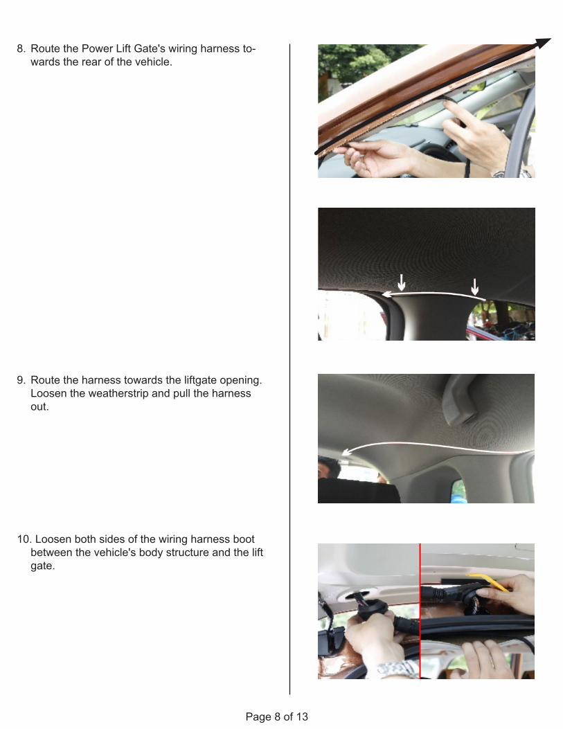
8. Route the Power Lift Gate's wiring harness to-wards the rear of the vehicle.
9. Route the harness towards the liftgate opening. Loosen the weatherstrip and pull the harness out.
10. Loosen both sides of the wiring harness boot between the vehicle's body structure and the lift gate.
Page 9 of 13
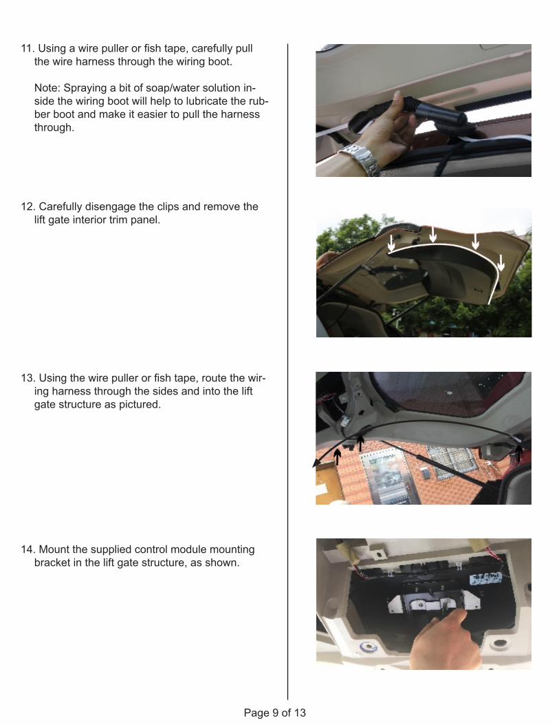
11. Using a wire puller or fish tape, carefully pull the wire harness through the wiring boot.
Note: Spraying a bit of soap/water solution in-side the wiring boot will help to lubricate the rub-ber boot and make it easier to pull the harness through.
12. Carefully disengage the clips and remove the lift gate interior trim panel.
13. Using the wire puller or fish tape, route the wir-ing harness through the sides and into the lift gate structure as pictured.
14. Mount the supplied control module mounting bracket in the lift gate structure, as shown.
Page 10 of 13
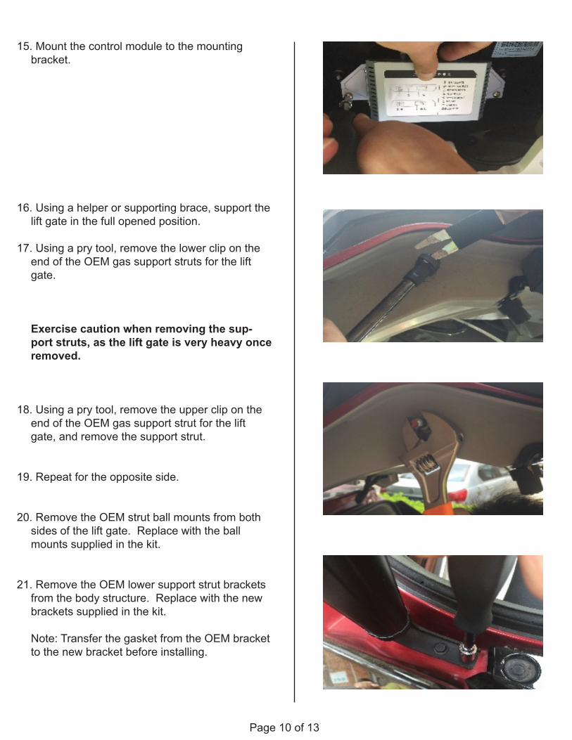
15. Mount the control module to the mounting bracket.
16. Using a helper or supporting brace, support the lift gate in the full opened position.
17. Using a pry tool, remove the lower clip on the end of the OEM gas support struts for the lift gate.
Exercise caution when removing the sup-port struts, as the lift gate is very heavy once removed.
18. Using a pry tool, remove the upper clip on the end of the OEM gas support strut for the lift gate, and remove the support strut.
19. Repeat for the opposite side.
20. Remove the OEM strut ball mounts from both sides of the lift gate. Replace with the ball mounts supplied in the kit.
21. Remove the OEM lower support strut brackets from the body structure. Replace with the new brackets supplied in the kit.
Note: Transfer the gasket from the OEM bracket to the new bracket before installing.
Page 11 of 13
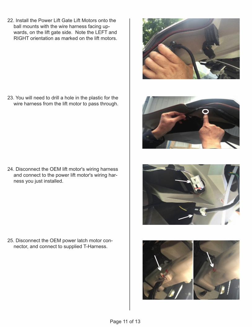
22. Install the Power Lift Gate Lift Motors onto the ball mounts with the wire harness facing up-wards, on the lift gate side. Note the LEFT and RIGHT orientation as marked on the lift motors.
23. You will need to drill a hole in the plastic for the wire harness from the lift motor to pass through.
24. Disconnect the OEM lift motor's wiring harness and connect to the power lift motor's wiring har-ness you just installed.
25. Disconnect the OEM power latch motor con-nector, and connect to supplied T-Harness.
Page 12 of 13
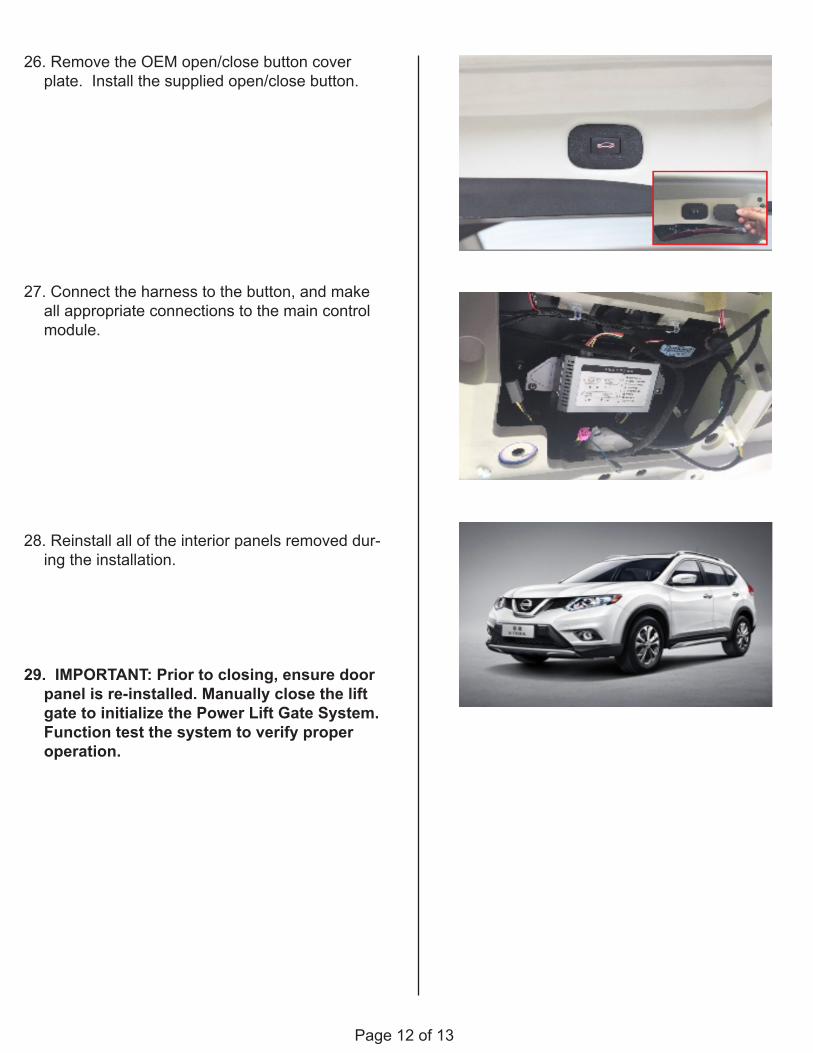
26. Remove the OEM open/close button cover plate. Install the supplied open/close button.
27. Connect the harness to the button, and make all appropriate connections to the main control module.
28. Reinstall all of the interior panels removed dur-ing the installation.
29. IMPORTANT: Prior to closing, ensure door panel is re-installed. Manually close the lift gate to initialize the Power Lift Gate System. Function test the system to verify proper operation.
Page 13 of 13
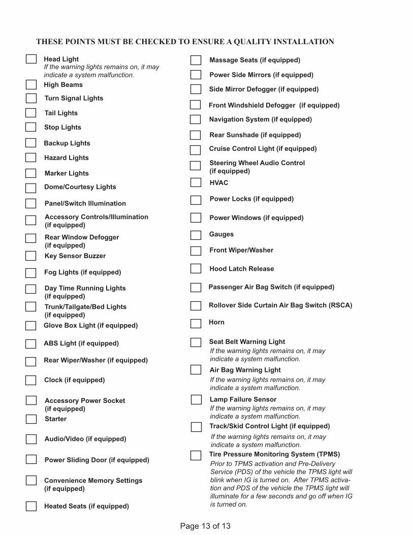
THESE POINTS MUST BE CHECKED TO ENSURE A QUALITY INSTALLATION
Head Light
High Beams
Turn Signal Lights
Tail Lights
Stop Lights
Backup Lights
Hazard Lights
Marker Lights
Dome/Courtesy Lights
Panel/Switch Illumination
Accessory Controls/Illumination (if equipped)
Rear Window Defogger (if equipped)Key Sensor Buzzer
Fog Lights (if equipped)
Day Time Running Lights (if equipped)Trunk/Tailgate/Bed Lights (if equipped)Glove Box Light (if equipped)
ABS Light (if equipped)
Rear Wiper/Washer (if equipped)
Clock (if equipped)
Accessory Power Socket (if equipped)Starter
Audio/Video (if equipped)
Power Sliding Door (if equipped)
If the warning lights remains on, it may indicate a system malfunction.
Convenience Memory Settings (if equipped)
Heated Seats (if equipped)
Massage Seats (if equipped)
Power Side Mirrors (if equipped)
Side Mirror Defogger (if equipped)
Front Windshield Defogger (if equipped)
Navigation System (if equipped)
Rear Sunshade (if equipped)
Cruise Control Light (if equipped)
Steering Wheel Audio Control (if equipped)HVAC
Power Locks (if equipped)
Power Windows (if equipped)
Gauges
Front Wiper/Washer
Hood Latch Release
Passenger Air Bag Switch (if equipped)
Rollover Side Curtain Air Bag Switch (RSCA)
Horn
Seat Belt Warning Light
Air Bag Warning Light
Lamp Failure Sensor
Track/Skid Control Light (if equipped)
If the warning lights remains on, it may indicate a system malfunction.
If the warning lights remains on, it may indicate a system malfunction.
If the warning lights remains on, it may indicate a system malfunction.
If the warning lights remains on, it may indicate a system malfunction.Tire Pressure Monitoring System (TPMS)Prior to TPMS activation and Pre-Delivery Service (PDS) of the vehicle the TPMS light will blink when IG is turned on. After TPMS activa-tion and PDS of the vehicle the TPMS light will illuminate for a few seconds and go off when IG is turned on.