Embed Size (px)
Citation preview
OR
EG
ON
INS
TALL
ATI
ON
MA
NU
AL
INDIVIDUAL HOMEWASTEWATER TREATMENT PLANT
with
PROGRESS THROUGH SERVICE SINCE 1906
SINGULAIR®
comprehensive protection, guaranteed

A dynamic combination of
electro-mechanical equipment, solid state
technology and web-based monitoring
that translates to increased property
value, performance certified for you
Consider the facts:• The Singulair Bio-Kinetic System meets or exceeds
government standards. The Singulair System is per-
formance certified and listed by NSF International.
The Singulair is certified to NSF Standard 40 and
our Bio-Kinetic System is certified to NSF Standard
46. Underwriters Laboratories and the Canadian
Standards Association have recognized, certified
and/or listed all electromechanical components.
The auto dialer telemetry system is licensed by the
Federal Communications Commission.
• The Bio-Kinetic System includes 3 positive filtration
zones with 8 independent settling zones.
• 48-hour retention in the Singulair System reduces
pumping frequency as compared to smaller
capacity systems.
• Operating costs are low. The only electrical compo-
nent is our low RPM aerator.
• Excessive hydraulic flows can cause major problems
for septic tanks, sand filters and any treatment
method that does not provide flow equalization.
The exclusive non-mechanical flow equalization
feature of our Bio-Kinetic System guarantees that
all incoming wastewater is fully treated, regardless
of heavy use periods.
• You can install an efficient Singulair plant for about
the same cost as an old-fashioned septic tank.
• Eliminates odors and all unsightly, unsanitary
conditions so common with septic tanks.
• Durable, reliable components are safely installed
out-of-sight below grade. No exposed power
cords, compressors, filters or air lines accessible to
children or pets.
• No need to purchase a separate tank – our
precast concrete pretreatment chamber is part
of the Singulair System.
• The Singulair System automatically equalizes
influent and effluent flow through all treatment
and disposal stages. Flow variations from guests,
parties or vacations do not effect treatment
performance.
• All flow is equalized an average of 50% at the
NSF Standard 40 600 GPD (gallons per day) design
loading pattern.
• Your local, factory-trained, certified and licensed
Norweco distributor sells, installs and services your
Bio-Kinetic System with pride. You’ll find your
distributor’s name and contact info conveniently
posted on the system’s control center.
Singulair® rivals the performance of the world’s most advanced treatment equipment
The new state-of-the-art Singulair treatment system is the trouble-free, energy-efficient alternative to that out-dated, unmanageable septic tank. It sets a new standard for properties that are not connected to centralized sewers. It quietly, efficiently and automatically treats all incoming wastewater, returning harmless effluent to the environment in just 24-hours. Because it operates only 30-minutes every hour, the new Singulair uses half the energy required by continuous-run systems.
We’ve been providing progress through service since 1906. When you consider the facts presented in this brochure, you will see why Norweco is recognized everywhere as providing today’s answer for the protection of tomorrow’s environment.
solutions i n w a s t e w a t e r t r e a t m e n t

Norweco distributors are located throughout the United States
and much of the rest of the world. Research, product develop-
ment, manufacturing, marketing and sales support are conducted
inside our offices and factory in Norwalk, Ohio. Everyone at
Norweco is committed to shaping the future of our industry.
Today’s Answer for the Protection of Tomorrow’s Environment
Specify Singulair®
Your local Norweco distributor is fully trained to install your Singulair
System and any other Norweco product you choose to protect your
environment. Each of our distributors has completed a nationally
accredited Singulair factory-training program.
The Singulair System comes to you complete, including delivery, tank
setting, equipment installation, plant start-up and service. A series of
service and adjustment inspections are scheduled for the first two years
of operation at the time your system is installed. These inspections are
included in the sale so that your system continues to perform at the
highest level to protect you and your investment. Extended service
contracts are also available from your Norweco distributor.
engineering t h e f u t u r e of water and wastewater treatment
A dynamic combination of
electro-mechanical equipment, solid state
technology and web-based monitoring
that translates to increased property
value, performance certified for you
Consider the facts:• The Singulair Bio-Kinetic System meets or exceeds
government standards. The Singulair System is per-
formance certified and listed by NSF International.
The Singulair is certified to NSF Standard 40 and
our Bio-Kinetic System is certified to NSF Standard
46. Underwriters Laboratories and the Canadian
Standards Association have recognized, certified
and/or listed all electromechanical components.
The auto dialer telemetry system is licensed by the
Federal Communications Commission.
• The Bio-Kinetic System includes 3 positive filtration
zones with 8 independent settling zones.
• 48-hour retention in the Singulair System reduces
pumping frequency as compared to smaller
capacity systems.
• Operating costs are low. The only electrical compo-
nent is our low RPM aerator.
• Excessive hydraulic flows can cause major problems
for septic tanks, sand filters and any treatment
method that does not provide flow equalization.
The exclusive non-mechanical flow equalization
feature of our Bio-Kinetic System guarantees that
all incoming wastewater is fully treated, regardless
of heavy use periods.
• You can install an efficient Singulair plant for about
the same cost as an old-fashioned septic tank.
• Eliminates odors and all unsightly, unsanitary
conditions so common with septic tanks.
• Durable, reliable components are safely installed
out-of-sight below grade. No exposed power
cords, compressors, filters or air lines accessible to
children or pets.
• No need to purchase a separate tank – our
precast concrete pretreatment chamber is part
of the Singulair System.
• The Singulair System automatically equalizes
influent and effluent flow through all treatment
and disposal stages. Flow variations from guests,
parties or vacations do not effect treatment
performance.
• All flow is equalized an average of 50% at the
NSF Standard 40 600 GPD (gallons per day) design
loading pattern.
• Your local, factory-trained, certified and licensed
Norweco distributor sells, installs and services your
Bio-Kinetic System with pride. You’ll find your
distributor’s name and contact info conveniently
posted on the system’s control center.
Singulair® rivals the performance of the world’s most advanced treatment equipment
The new state-of-the-art Singulair treatment system is the trouble-free, energy-efficient alternative to that out-dated, unmanageable septic tank. It sets a new standard for properties that are not connected to centralized sewers. It quietly, efficiently and automatically treats all incoming wastewater, returning harmless effluent to the environment in just 24-hours. Because it operates only 30-minutes every hour, the new Singulair uses half the energy required by continuous-run systems.
We’ve been providing progress through service since 1906. When you consider the facts presented in this brochure, you will see why Norweco is recognized everywhere as providing today’s answer for the protection of tomorrow’s environment.
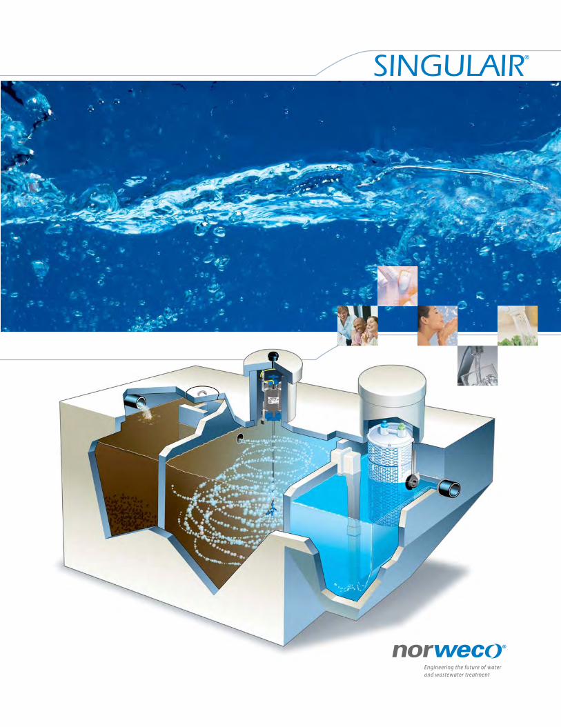
Inlet
Pretreatment Chamber
Aeration Chamber
Precast Concrete Tank
Singulair® Aerator
Outlet
Bio-Static® Sludge Return
Optional Bio-Neutralizer®
Dechlorination TabletsRELIABLY, SAFELY AND ECONOMICALLY REDUCE RESIDUAL
CHLORINE AND PROTECT ENVIRONMENTALLY SENSITIVE
SURFACE WATER WITH OUR SPECIALLY FORMULATED
TABLETS. PACKAGED IN EASY TO HANDLE, RE-SEALABLE
CONTAINERS, OUR BIO-NEUTRALIZER DECHLORINATION
TABLETS ARE AVAILABLE IN 25 AND 45 POUND POLYETHYL-
ENE PAILS FROM YOUR LOCAL NORWECO DISTRIBUTOR.
Bio-Kinetic® SystemConstructed entirely of plastic and rubber components that are
impervious to this environment, our Bio-Kinetic System combines
filtration, settling, non-mechanical flow equalization, optional
disinfection, adjustable outlet weir and optional dechlorination
features into a single, revolutionary package.
Precast Concrete TankEvery Singulair System is constructed of high quality, non-corrosive
materials under our rigid quality control standards. The tank,
access risers and cover are reinforced precast concrete manufac-
tured locally by your factory-trained, licensed Norweco distributor.
Inspection CoverAccess is safe and easy.
OutletOnly a clear, safe and odorless liquid exits the system here for
return to your environment.
Bio-Kinetic® System
Control Center EVERY SINGULAIR AERATOR IS INSTALLED WITH A
SOLID STATE ELECTRICAL CONTROL CENTER. EACH IS
EQUIPPED WITH RESETTABLE CURRENT SENSOR,
ON/OFF SELECTOR SWITCH, RED WARNING LIGHT,
TIME CLOCK, AUDIBLE ALARM, AUXILIARY INPUTS
AND FCC LICENSED AUTODIALER FOR REMOTE
MONITORING OF INDIVIDUAL COMPONENTS.
InletUntreated wastewater enters the system here.
Pretreatment ChamberWastewater enters at the Singulair inlet and is equalized here as
anaerobic bacteria and gravity precondition it.
Aeration ChamberHere, safe, living aerobic bacteria convert the wastewater into
stable substances. Flow equalization maximizes this biological
oxidation and assures 24-hour retention and treatment.
Aerator provides complete treatmentOur exclusive aerator infuses the fresh air that safe, living micro-
organisms require to fully digest and treat wastewater inside the
Aeration Chamber. Powered by our 1725 RPM, 115 volt, fractional
horsepower motor, our quiet, reliable aerator is inexpensive to
operate, reduces heat build up and dramatically increases bearing
life. Each aerator is precision engineered, tested and certified to
operate only 30-minutes per hour. Only the stainless steel aspirator
shaft and reinforced nylon aspirator come in contact with liquid in
the Aeration Chamber.
Clarification ChamberFlow equalization enhances the settling of biologically active
substances inside the Clarification Chamber. Wastewater has now
been converted into clarified liquids in this chamber.
Flow Equalization PortsThey control the flow through all upstream and downstream
processes and they regulate the amount of treated effluent that
can enter the Bio-Kinetic System.
Clarification Chamber
Inspection Cover

220 Republic Street Norwalk, Ohio, U.S.A. 44857-1156PH: 419.668.4471FAX: 419.663.5440www.norweco.com
© MMVII NORWECO
Singulair is warranted against defects in material
and workmanship under normal use and service by a
comprehensive 50 year Warranty and Exchange Program.
This 2 year Limited Warranty and 48 year Exchange
provides single source protection and covers all system components.
Complete Warranty and Exchange information, a Warranty
Registration Card and Owner’s Manual are included with purchase.
The Singulair Bio-Kinetic System components have
been listed, licensed and/or certified by each of the
following agencies/organizations.
SINGULAIR®
comprehensive protection, guaranteed
Progress Through Service Since 1906
We engineer, manufacture, install and maintain advanced water and
wastewater treatment technologies for residential properties, com-
munities and commercial properties that are not connected to sewer
lines. Norweco treatment systems are in service all over the world.
Norweco®, Norweco.com®, Singulair®, Modulair®, Travalair®, Lift-Rail®,
Microsonic®, Bio-Dynamic®, Bio-Sanitizer®, Bio-Neutralizer®, Bio-Kinetic®,
Bio-Static®, Bio-Gem®, Bio-Regeneration®, Bio-Perc®, Blue Crystal®, ClearCheck®,
ChemCheck®, Service Pro®, Grease Buster® and “BUSTER” logo are all
registered trademarks of Norwalk Wastewater Equipment Company, Inc.
Today’s Answer for the Protection of Tomorrow’s Environment
Specify Singulair®
Your local Norweco distributor is fully trained to install your Singulair
System and any other Norweco product you choose to protect your
environment. Each of our distributors has completed a nationally
accredited Singulair factory-training program.
The Singulair System comes to you complete, including delivery, tank
setting, equipment installation, plant start-up and service. A series of
service and adjustment inspections are scheduled for the first two years
of operation at the time your system is installed. These inspections are
included in the sale so that your system continues to perform at the
highest level to protect you and your investment. Extended service
contracts are also available from your Norweco distributor.
SP
EC
IFIC
AT
ION
S
GENERAL SPECIFICATIONS
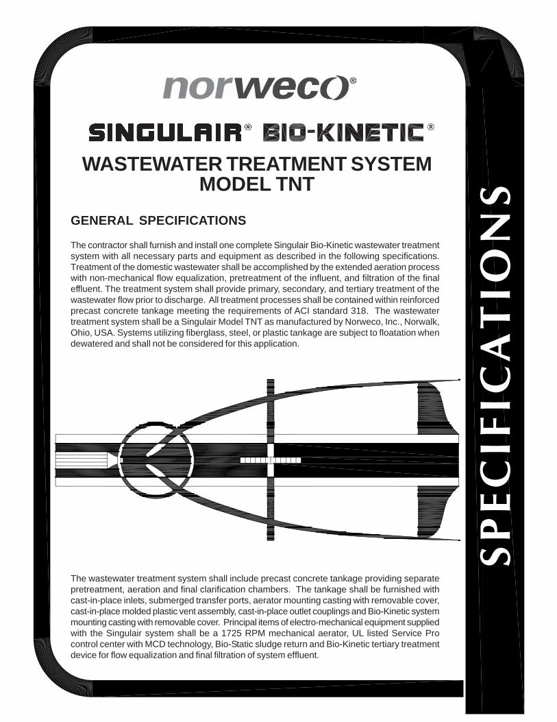
The contractor shall furnish and install one complete Singulair Bio-Kinetic wastewater treatmentsystem with all necessary parts and equipment as described in the following specifications.Treatment of the domestic wastewater shall be accomplished by the extended aeration processwith non-mechanical flow equalization, pretreatment of the influent, and filtration of the finaleffluent. The treatment system shall provide primary, secondary, and tertiary treatment of thewastewater flow prior to discharge. All treatment processes shall be contained within reinforcedprecast concrete tankage meeting the requirements of ACI standard 318. The wastewatertreatment system shall be a Singulair Model TNT as manufactured by Norweco, Inc., Norwalk,Ohio, USA. Systems utilizing fiberglass, steel, or plastic tankage are subject to floatation whendewatered and shall not be considered for this application.
WASTEWATER TREATMENT SYSTEM
The wastewater treatment system shall include precast concrete tankage providing separatepretreatment, aeration and final clarification chambers. The tankage shall be furnished withcast-in-place inlets, submerged transfer ports, aerator mounting casting with removable cover,cast-in-place molded plastic vent assembly, cast-in-place outlet couplings and Bio-Kinetic systemmounting casting with removable cover. Principal items of electro-mechanical equipment suppliedwith the Singulair system shall be a 1725 RPM mechanical aerator, UL listed Service Procontrol center with MCD technology, Bio-Static sludge return and Bio-Kinetic tertiary treatmentdevice for flow equalization and final filtration of system effluent.
MODEL TNT
OPERATING CONDITIONS
Total holding capacity of the system shall provide a minimum of 48 hour retention of the daily flow. The pretreatment chambershall provide at least 18 hour retention, the extended aeration chamber shall provide at least 24 hour retention, and the clarificationchamber shall provide at least 6 hour retention. The non-mechanical flow equalization device shall increase each individualchamber and total system retention time in direct proportion to loading. Design of the system shall include a compartmentedtank and non-mechanical flow equalization device to insure successful treatment performance without upset even when thesignificant runoff period is six hours. Hydraulic design considerations of the system and flow equalization device shall be suchthat intermittent peak flow factors as high as four shall not upset hydraulic reliability within the system. Capability of the systemto perform as outlined, when built by an approved manufacturer, shall be certified by an independent testing laboratory andapproved for use by the local governing regulatory agency.
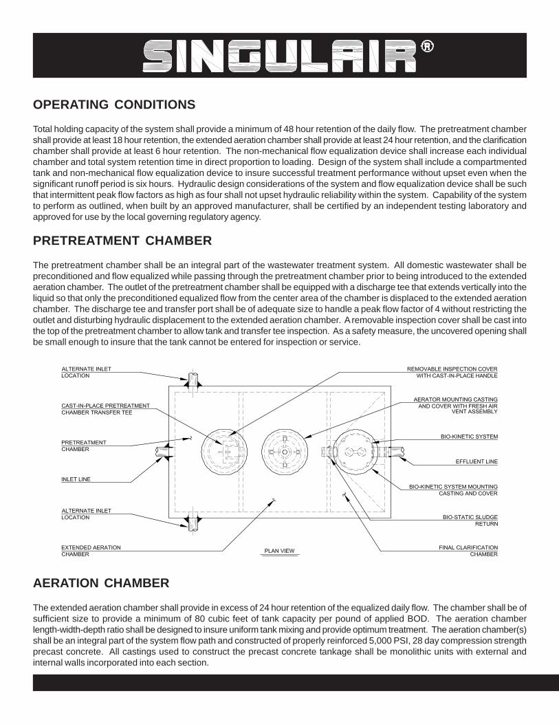
PRETREATMENT CHAMBER
The pretreatment chamber shall be an integral part of the wastewater treatment system. All domestic wastewater shall bepreconditioned and flow equalized while passing through the pretreatment chamber prior to being introduced to the extendedaeration chamber. The outlet of the pretreatment chamber shall be equipped with a discharge tee that extends vertically into theliquid so that only the preconditioned equalized flow from the center area of the chamber is displaced to the extended aerationchamber. The discharge tee and transfer port shall be of adequate size to handle a peak flow factor of 4 without restricting theoutlet and disturbing hydraulic displacement to the extended aeration chamber. A removable inspection cover shall be cast intothe top of the pretreatment chamber to allow tank and transfer tee inspection. As a safety measure, the uncovered opening shallbe small enough to insure that the tank cannot be entered for inspection or service.
AERATION CHAMBER
The extended aeration chamber shall provide in excess of 24 hour retention of the equalized daily flow. The chamber shall be ofsufficient size to provide a minimum of 80 cubic feet of tank capacity per pound of applied BOD. The aeration chamberlength-width-depth ratio shall be designed to insure uniform tank mixing and provide optimum treatment. The aeration chamber(s)shall be an integral part of the system flow path and constructed of properly reinforced 5,000 PSI, 28 day compression strengthprecast concrete. All castings used to construct the precast concrete tankage shall be monolithic units with external andinternal walls incorporated into each section.
FINAL CLARIFICATION CHAMBER
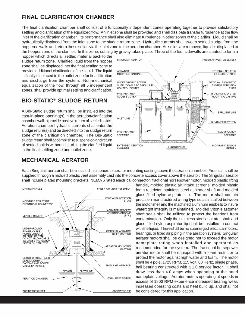
The final clarification chamber shall consist of 5 functionally independent zones operating together to provide satisfactorysettling and clarification of the equalized flow. An inlet zone shall be provided and shall dissipate transfer turbulence at the flowinlet of the clarification chamber. Its performance shall also eliminate turbulence in other zones of the clarifier. Liquid shall behydraulically displaced from the inlet zone to the sludge return zone. Hydraulic currents shall sweep settled sludge from thehoppered walls and return these solids via the inlet zone to the aeration chamber. As solids are removed, liquid is displaced tothe hopper zone of the clarifier. In this zone, settling by gravity takes place. Three of the four sidewalls are slanted to form ahopper which directs all settled material back to thesludge return zone. Clarified liquid from the hopperzone shall be displaced into the final settling zone toprovide additional clarification of the liquid. The liquidis finally displaced to the outlet zone for final filtrationand discharge from the system. Non-mechanicalequalization of the flow, through all 5 independentzones, shall provide optimal settling and clarification.
BIO-STATIC® SLUDGE RETURN
A Bio-Static sludge return shall be installed into thecast-in-place opening(s) in the aeration/clarificationchamber wall to provide positive return of settled solids.Aeration chamber hydraulic currents shall enter thesludge return(s) and be directed into the sludge returnzone of the clarification chamber. The Bio-Staticsludge return shall accomplish resuspension and returnof settled solids without disturbing the clarified liquidin the final settling zone and outlet zone.
MECHANICAL AERATOR
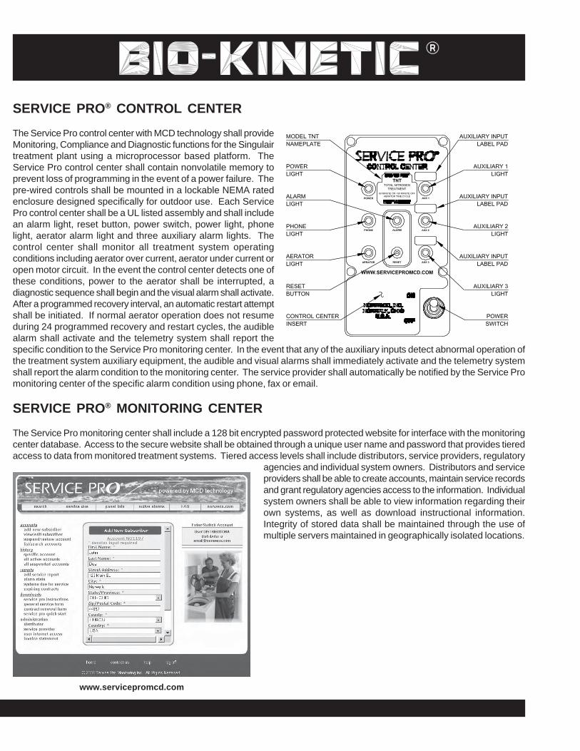
Each Singulair aerator shall be installed in a concrete aerator mounting casting above the aeration chamber. Fresh air shall besupplied through a molded plastic vent assembly cast into the concrete access cover above the aerator. The Singulair aeratorshall include plated mounting brackets, NEMA 6 rated electrical connector, fractional horsepower motor, molded plastic lifting
handle, molded plastic air intake screens, molded plasticfoam restrictor, stainless steel aspirator shaft and moldedglass-filled nylon aspirator tip. The motor shall containprecision manufactured o-ring type seals installed betweenthe motor shell and the machined aluminum endbells to insurewatertight integrity is maintained. Molded Viton elastomershaft seals shall be utilized to protect the bearings fromcontamination. Only the stainless steel aspirator shaft andglass-filled nylon aspirator tip shall be installed in contactwith the liquid. There shall be no submerged electrical motors,bearings, or fixed air piping in the aeration system. Singulairaerator motors shall be designed not to exceed the motornameplate rating when installed and operated asrecommended for the system. The fractional horsepoweraerator motor shall be equipped with a foam restrictor toprotect the motor against high water and foam. The motorshall be 4 pole, 1725 RPM, 115 volt, 60 Hertz, single phase,ball bearing constructed with a 1.0 service factor. It shalldraw less than 4.0 amps when operating at the ratednameplate voltage. Aerator motors operating at speeds inexcess of 1800 RPM experience increased bearing wear,increased operating costs and heat build up, and shall notbe considered for this application.
SERVICE PRO® CONTROL CENTER
The Service Pro control center with MCD technology shall provideMonitoring, Compliance and Diagnostic functions for the Singulairtreatment plant using a microprocessor based platform. TheService Pro control center shall contain nonvolatile memory toprevent loss of programming in the event of a power failure. Thepre-wired controls shall be mounted in a lockable NEMA ratedenclosure designed specifically for outdoor use. Each ServicePro control center shall be a UL listed assembly and shall includean alarm light, reset button, power switch, power light, phonelight, aerator alarm light and three auxiliary alarm lights. Thecontrol center shall monitor all treatment system operatingconditions including aerator over current, aerator under current oropen motor circuit. In the event the control center detects one ofthese conditions, power to the aerator shall be interrupted, adiagnostic sequence shall begin and the visual alarm shall activate.After a programmed recovery interval, an automatic restart attemptshall be initiated. If normal aerator operation does not resumeduring 24 programmed recovery and restart cycles, the audiblealarm shall activate and the telemetry system shall report thespecific condition to the Service Pro monitoring center. In the event that any of the auxiliary inputs detect abnormal operation ofthe treatment system auxiliary equipment, the audible and visual alarms shall immediately activate and the telemetry systemshall report the alarm condition to the monitoring center. The service provider shall automatically be notified by the Service Promonitoring center of the specific alarm condition using phone, fax or email.
SERVICE PRO® MONITORING CENTER
The Service Pro monitoring center shall include a 128 bit encrypted password protected website for interface with the monitoringcenter database. Access to the secure website shall be obtained through a unique user name and password that provides tieredaccess to data from monitored treatment systems. Tiered access levels shall include distributors, service providers, regulatory
agencies and individual system owners. Distributors and serviceproviders shall be able to create accounts, maintain service recordsand grant regulatory agencies access to the information. Individualsystem owners shall be able to view information regarding theirown systems, as well as download instructional information.Integrity of stored data shall be maintained through the use ofmultiple servers maintained in geographically isolated locations.
www.servicepromcd.com
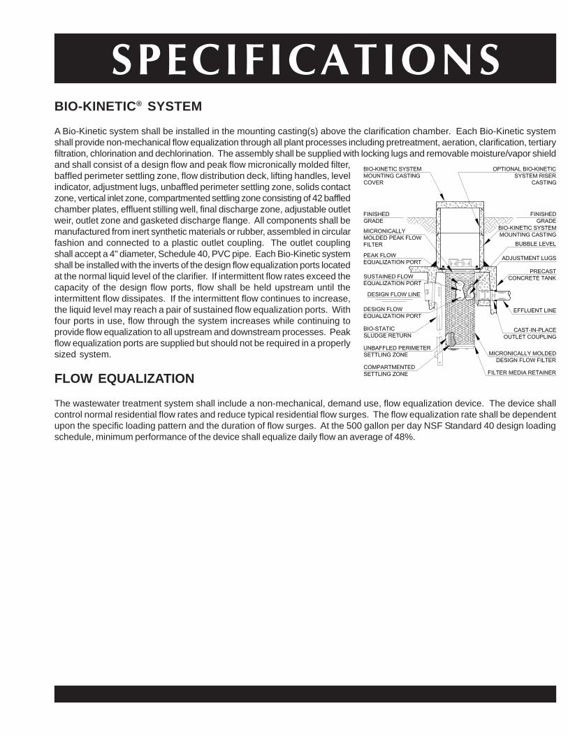
BIO-KINETIC® SYSTEM
A Bio-Kinetic system shall be installed in the mounting casting(s) above the clarification chamber. Each Bio-Kinetic systemshall provide non-mechanical flow equalization through all plant processes including pretreatment, aeration, clarification, tertiaryfiltration, chlorination and dechlorination. The assembly shall be supplied with locking lugs and removable moisture/vapor shieldand shall consist of a design flow and peak flow micronically molded filter,baffled perimeter settling zone, flow distribution deck, lifting handles, levelindicator, adjustment lugs, unbaffled perimeter settling zone, solids contactzone, vertical inlet zone, compartmented settling zone consisting of 42 baffledchamber plates, effluent stilling well, final discharge zone, adjustable outletweir, outlet zone and gasketed discharge flange. All components shall bemanufactured from inert synthetic materials or rubber, assembled in circularfashion and connected to a plastic outlet coupling. The outlet couplingshall accept a 4" diameter, Schedule 40, PVC pipe. Each Bio-Kinetic systemshall be installed with the inverts of the design flow equalization ports locatedat the normal liquid level of the clarifier. If intermittent flow rates exceed thecapacity of the design flow ports, flow shall be held upstream until theintermittent flow dissipates. If the intermittent flow continues to increase,the liquid level may reach a pair of sustained flow equalization ports. Withfour ports in use, flow through the system increases while continuing toprovide flow equalization to all upstream and downstream processes. Peakflow equalization ports are supplied but should not be required in a properlysized system.
FLOW EQUALIZATION
The wastewater treatment system shall include a non-mechanical, demand use, flow equalization device. The device shallcontrol normal residential flow rates and reduce typical residential flow surges. The flow equalization rate shall be dependentupon the specific loading pattern and the duration of flow surges. At the 500 gallon per day NSF Standard 40 design loadingschedule, minimum performance of the device shall equalize daily flow an average of 48%.
SPECIFICATIONS
PROGRESS THROUGH SERVICE SINCE 1906
DISTRIBUTED LOCALLY BY:
WARRANTY AND EXCHANGE PROGRAM
The manufacturer shall provide a two year limited warranty for theSingulair aerator, Service Pro control center, Bio-Kinetic system andSingulair precast concrete tank. A comprehensive exchange programoffers Singulair owners an additional forty-eight years of equipmentprotection. The distributor shall provide warranty and exchangeprogram details to the regulatory agency, contractor and customer asrequired.
EQUIPMENT MANUFACTURER
The equipment specified herein shall be the product of a manufacturer having a minimum of seven yearsexperience in the construction of prefabricated wastewater treatment equipment and systems. Bids shall beprepared on the basis of the equipment and material specified herein for purposes of determining the low bid.This is not done, however, to eliminate other products or equipment of equal quality and efficiency. If equipmentis to be substituted, approval of such substitution must be made prior to execution of any order. It is assumedthat substitution will result in a reduction of cost to the contractor and that if accepted, these savings will bepassed along by a reduction in the base bid.
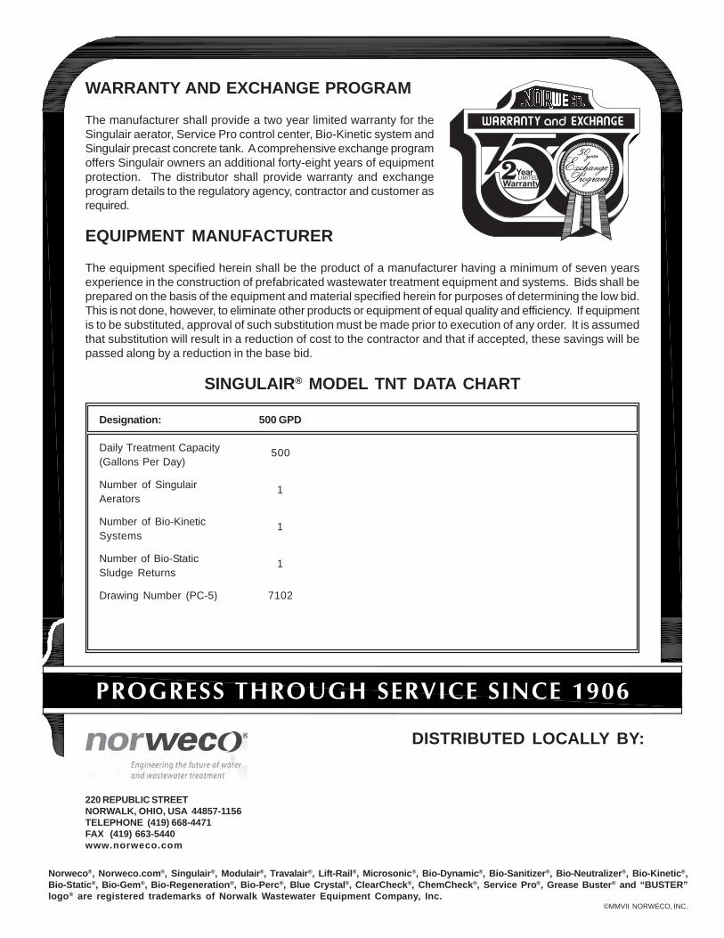
SINGULAIR® MODEL TNT DATA CHART
220 REPUBLIC STREETNORWALK, OHIO, USA 44857-1156TELEPHONE (419) 668-4471FAX (419) 663-5440www.norweco.com
Designation: 500 GPD
Daily Treatment Capacity 500(Gallons Per Day)
Number of Singulair 1Aerators
Number of Bio-Kinetic 1Systems
Number of Bio-Static 1Sludge Returns
Drawing Number (PC-5) 7102
Norweco®, Norweco.com®, Singulair®, Modulair®, Travalair®, Lift-Rail®, Microsonic®, Bio-Dynamic®, Bio-Sanitizer®, Bio-Neutralizer®, Bio-Kinetic®,Bio-Static®, Bio-Gem®, Bio-Regeneration®, Bio-Perc®, Blue Crystal®, ClearCheck®, ChemCheck®, Service Pro®, Grease Buster® and “BUSTER”logo® are registered trademarks of Norwalk Wastewater Equipment Company, Inc.
©MMVII NORWECO, INC.
BIO-KINETIC® WASTEWATER TREATMENT SYSTEM
INSTALLATION INSTRUCTIONSEach Singulair Bio-Kinetic wastewater treatment system is sold complete including: delivery and installation of the tank andBio-Static sludge return; installation and start-up of the mechanical aerator, control center and Bio-Kinetic system; two-yearlimited warranty with four prescheduled service inspections at six month intervals; and fifty-year aerator exchange program. Aclear outline of responsibilities when the order is placed will simplify installation of the system and establish a sound workingrelationship with the installing contractor and local health department.
INSTALLATION PROCEDURE
Installation of the Singulair system normally occurs in twophases. First, the precast concrete tankage is deliveredand installed at the contractor’s convenience. Eachelectrical control center, underground electrical servicecable and Bio-Static sludge return is also installed at thistime. Only when the system is ready for start-up are theSingulair aerators and Bio-Kinetic systems delivered andinstalled. When the Singulair installer has completedequipment installation, he should also start-up and test theentire system and familiarize the owner with its operation.This installation procedure will assure efficient use of thecontractor’s and installer’s time and protect equipment frompossible damage or unauthorized start-up.
CONTACT THE LOCAL HEALTH DEPARTMENT
The contractor must contact the local health departmentprior to installation of the Singulair system and apply for aninstallation permit. The local Singulair distributor will havedrawings, specifications and performance data for thesystem on file with the health department. Normally, thecontractor will not be required to supply this informationto receive the installation permit. The health departmentmay request a drawing showing the proposed method ofeffluent disposal and location of the Singulair system inrelation to the building, property lines and potable watersupply. The health department may wish to inspect thesite and proposed point of discharge, take soil samples orrun percolation tests before issuing an installation permit.The contractor must find out if an inspection of the Singulairtank and sewer line will be required before backfilling isallowed.
DELIVERY TRUCK ACCESSIBILITY
Inform the contractor of the dimensions and weight of thedelivery truck. The excavation must be accessible withoutinterference from trees, shrubbery, power lines or otherobstacles. Earth from the excavation must be piledoutside the working area needed to operate the truck.Remind the contractor that extra charges will apply if theexcavation is not complete and readily accessible.
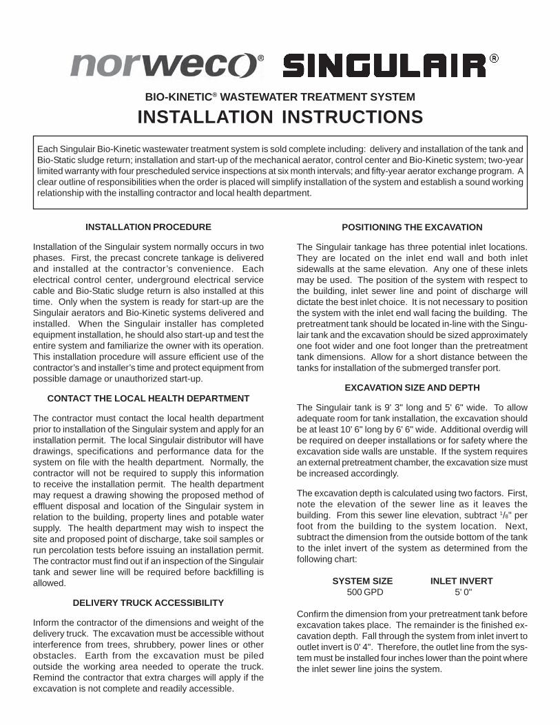
POSITIONING THE EXCAVATION
The Singulair tankage has three potential inlet locations.They are located on the inlet end wall and both inletsidewalls at the same elevation. Any one of these inletsmay be used. The position of the system with respect tothe building, inlet sewer line and point of discharge willdictate the best inlet choice. It is not necessary to positionthe system with the inlet end wall facing the building. Thepretreatment tank should be located in-line with the Singu-lair tank and the excavation should be sized approximatelyone foot wider and one foot longer than the pretreatmenttank dimensions. Allow for a short distance between thetanks for installation of the submerged transfer port.
EXCAVATION SIZE AND DEPTH
The Singulair tank is 9' 3" long and 5' 6" wide. To allowadequate room for tank installation, the excavation shouldbe at least 10' 6" long by 6' 6" wide. Additional overdig willbe required on deeper installations or for safety where theexcavation side walls are unstable. If the system requiresan external pretreatment chamber, the excavation size mustbe increased accordingly.
The excavation depth is calculated using two factors. First,note the elevation of the sewer line as it leaves thebuilding. From this sewer line elevation, subtract 1/8" perfoot from the building to the system location. Next,subtract the dimension from the outside bottom of the tankto the inlet invert of the system as determined from thefollowing chart:
SYSTEM SIZE INLET INVERT500 GPD 5' 0"
Confirm the dimension from your pretreatment tank beforeexcavation takes place. The remainder is the finished ex-cavation depth. Fall through the system from inlet invert tooutlet invert is 0' 4". Therefore, the outlet line from the sys-tem must be installed four inches lower than the point wherethe inlet sewer line joins the system.
MANUFACTURED BYNORWECO, INC.NORWALK, OHIOU.S.A. 44857www.norweco.com
©MCMXCVII NORWECO, INC. NORWALK, OHIO U.S.A.
INSTALLATION INSTRUCTIONS (Cont.)TANK LEVELING PAD
To insure that the tank bottom will be bearing the weightevenly, all tanks should be set on a four inch thick pad ofgravel, sand or fine crushed stone. The pad should beinstalled and leveled by the contractor before delivery andsetting of any tank takes place. The tank pad must beleveled to within 1/4" from side to side and end to end.
BACKFILLING THE TANKAGE
CAUTION: Do not allow dirt, debris or other material toenter the Singulair system during installation or backfilling.The Singulair system must be backfilled immediately afterinstallation. Any fine, granular jobsite material or backfillmay be used. Large clumps of earth, rocks or debris shouldnever be used to backfill around the system. The slantedendwall beneath the clarifier must be backfilled withparticular care. Be sure it is completely backfilled so thatfuture settling will not cause a low spot in the finished lawnor place an undue strain on the outlet line.
FILLING THE SYSTEM WITH WATER
The Singulair system should be filled with clean waterimmediately after installation. Water should be added asthe tank is being backfilled to equalize internal andexternal tank pressure. Fresh water is preferred but waterfrom a nearby pond may be used if it is free of silt and otherdebris. A septic tank pumping service should never beused to fill the Singulair system. If this is done, largeamounts of biologically untreatable materials may bedeposited in the system and they could interfere withsystem operation and performance.
INLET SEWER LINES
Only domestic wastewater must be allowed to enter theSingulair system. It is not intended to handle flows fromroofing down spouts, basement footer drains, sump pumppiping or garage and basement floor drains. If the sanitarysewer system must be used for disposal of these liquids, itmust be connected downstream of the Singulair system.Water softener backwash will affect system performanceand must not flow into the Singulair system.
ELECTRICAL POWER SUPPLY
A dedicated 115 volt AC single phase, 10 amp (minimum)60 Hertz circuit must be provided in the main electricalservice panel for each Singulair control center.
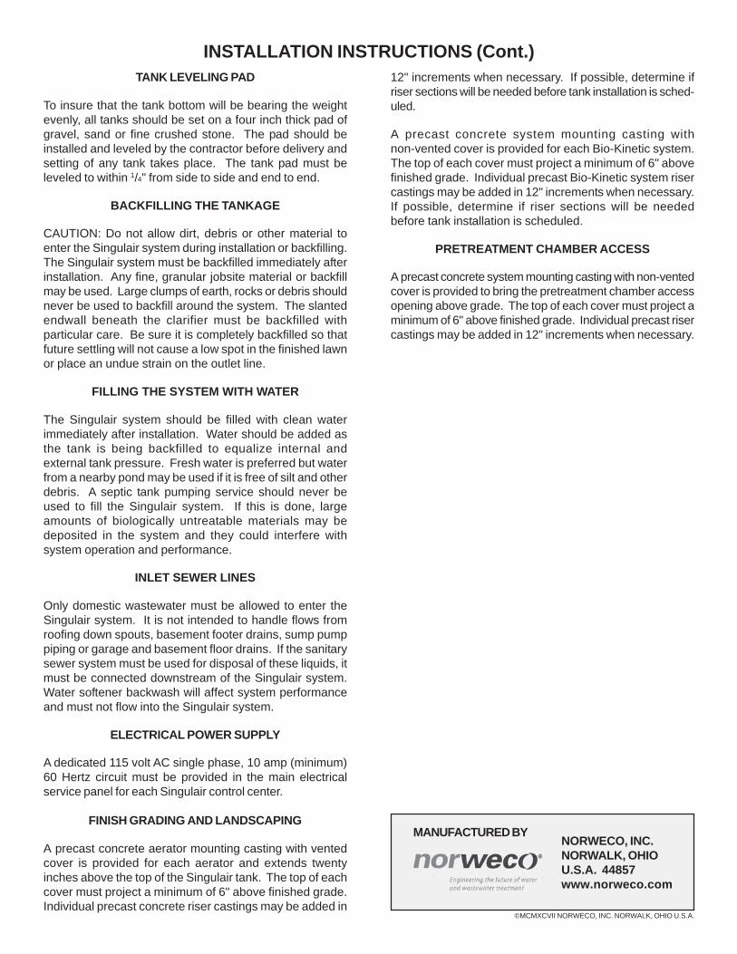
FINISH GRADING AND LANDSCAPING
A precast concrete aerator mounting casting with ventedcover is provided for each aerator and extends twentyinches above the top of the Singulair tank. The top of eachcover must project a minimum of 6" above finished grade.Individual precast concrete riser castings may be added in
12" increments when necessary. If possible, determine ifriser sections will be needed before tank installation is sched-uled.
A precast concrete system mounting casting withnon-vented cover is provided for each Bio-Kinetic system.The top of each cover must project a minimum of 6" abovefinished grade. Individual precast Bio-Kinetic system risercastings may be added in 12" increments when necessary.If possible, determine if riser sections will be neededbefore tank installation is scheduled.
PRETREATMENT CHAMBER ACCESS
A precast concrete system mounting casting with non-ventedcover is provided to bring the pretreatment chamber accessopening above grade. The top of each cover must project aminimum of 6" above finished grade. Individual precast risercastings may be added in 12" increments when necessary.
BIO-KINETIC® WASTEWATER TREATMENT SYSTEM
TANK DELIVERY AND SETTINGTo insure that all work proceeds safely and efficiently, check these items prior to delivery of the Singulair tankage.
✓ Does the driver have complete and accurate directions to the installation?
✓ Does the driver have the Singulair installer’s tool kit?
✓ Are the appropriate number of aerator mounting castings, Bio-Kinetic system mounting castings, extension risercastings and vented and non-vented access covers included?
✓ Is there an adequate supply of sealing material for the tank and all plumbing connections?
✓ Does the truck have the proper pick-up bar and cable (or chain)?
✓ Are the proper quantity and size of Bio-Static sludge returns installed?
✓ Are the proper quantity of Singulair control centers available for delivery with the tanks?
✓ Is there sufficient underground electrical cable to reach from the control center location to the tank?
PLEASE NOTE: The Singulair tank is constructed of monolithic castings and, if possible, the joints should be sealed at yourplant before setting. This will minimize tank loading, unloading and setting time at the site. The castings may be setindividually and sealed at the site if necessary. These instructions are written as if the castings will be installed separatelyand sealed at the site. However, the tank should be assembled and sealed in your plant if your tank handling and deliveryequipment will allow it. Otherwise, proceed with tank setting as outlined herein.
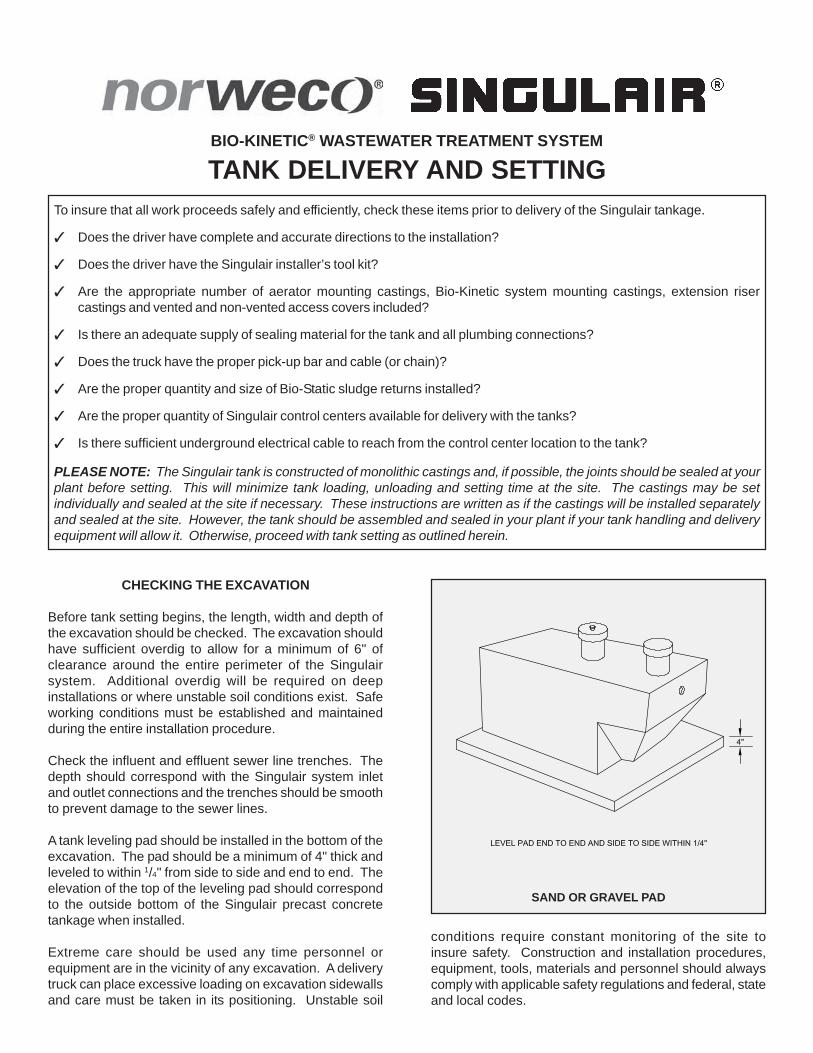
CHECKING THE EXCAVATION
Before tank setting begins, the length, width and depth ofthe excavation should be checked. The excavation shouldhave sufficient overdig to allow for a minimum of 6" ofclearance around the entire perimeter of the Singulairsystem. Additional overdig will be required on deepinstallations or where unstable soil conditions exist. Safeworking conditions must be established and maintainedduring the entire installation procedure.
Check the influent and effluent sewer line trenches. Thedepth should correspond with the Singulair system inletand outlet connections and the trenches should be smoothto prevent damage to the sewer lines.
A tank leveling pad should be installed in the bottom of theexcavation. The pad should be a minimum of 4" thick andleveled to within 1/4" from side to side and end to end. Theelevation of the top of the leveling pad should correspondto the outside bottom of the Singulair precast concretetankage when installed.
Extreme care should be used any time personnel orequipment are in the vicinity of any excavation. A deliverytruck can place excessive loading on excavation sidewallsand care must be taken in its positioning. Unstable soil
conditions require constant monitoring of the site toinsure safety. Construction and installation procedures,equipment, tools, materials and personnel should alwayscomply with applicable safety regulations and federal, stateand local codes.
SAND OR GRAVEL PAD
MANUFACTURED BYNORWECO, INC.NORWALK, OHIOU.S.A. 44857www.norweco.com
©MMIV NORWECO, INC. NORWALK, OHIO U.S.A.
TANK DELIVERY AND SETTING (Cont.)
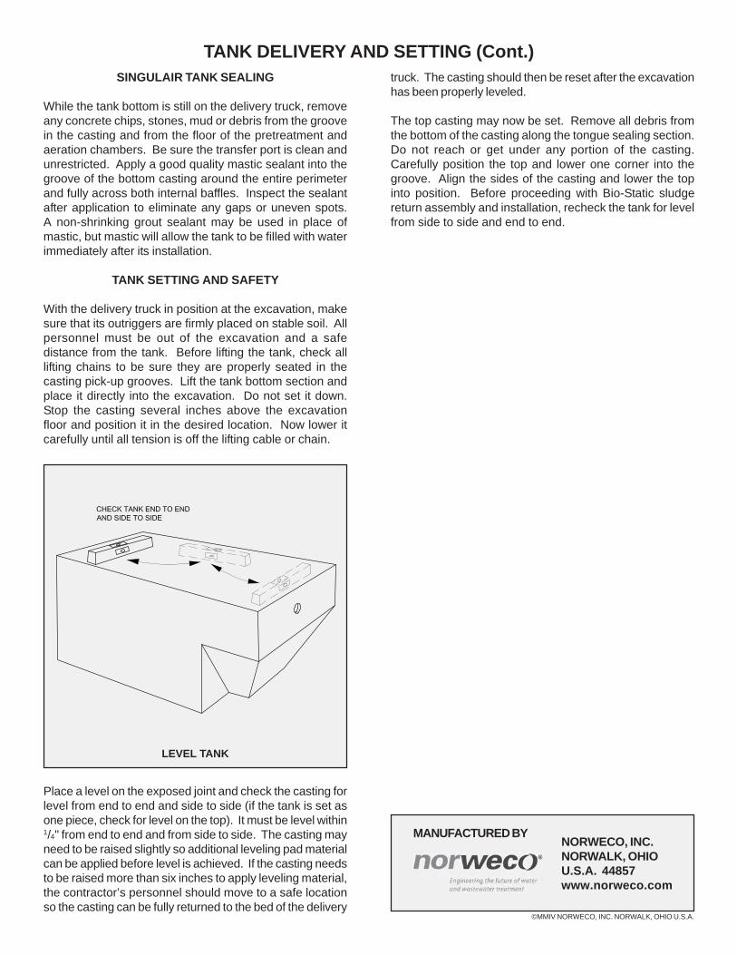
LEVEL TANK
SINGULAIR TANK SEALING
While the tank bottom is still on the delivery truck, removeany concrete chips, stones, mud or debris from the groovein the casting and from the floor of the pretreatment andaeration chambers. Be sure the transfer port is clean andunrestricted. Apply a good quality mastic sealant into thegroove of the bottom casting around the entire perimeterand fully across both internal baffles. Inspect the sealantafter application to eliminate any gaps or uneven spots.A non-shrinking grout sealant may be used in place ofmastic, but mastic will allow the tank to be filled with waterimmediately after its installation.
TANK SETTING AND SAFETY
With the delivery truck in position at the excavation, makesure that its outriggers are firmly placed on stable soil. Allpersonnel must be out of the excavation and a safedistance from the tank. Before lifting the tank, check alllifting chains to be sure they are properly seated in thecasting pick-up grooves. Lift the tank bottom section andplace it directly into the excavation. Do not set it down.Stop the casting several inches above the excavationfloor and position it in the desired location. Now lower itcarefully until all tension is off the lifting cable or chain.
Place a level on the exposed joint and check the casting forlevel from end to end and side to side (if the tank is set asone piece, check for level on the top). It must be level within1/4" from end to end and from side to side. The casting mayneed to be raised slightly so additional leveling pad materialcan be applied before level is achieved. If the casting needsto be raised more than six inches to apply leveling material,the contractor’s personnel should move to a safe locationso the casting can be fully returned to the bed of the delivery
truck. The casting should then be reset after the excavationhas been properly leveled.
The top casting may now be set. Remove all debris fromthe bottom of the casting along the tongue sealing section.Do not reach or get under any portion of the casting.Carefully position the top and lower one corner into thegroove. Align the sides of the casting and lower the topinto position. Before proceeding with Bio-Static sludgereturn assembly and installation, recheck the tank for levelfrom side to side and end to end.
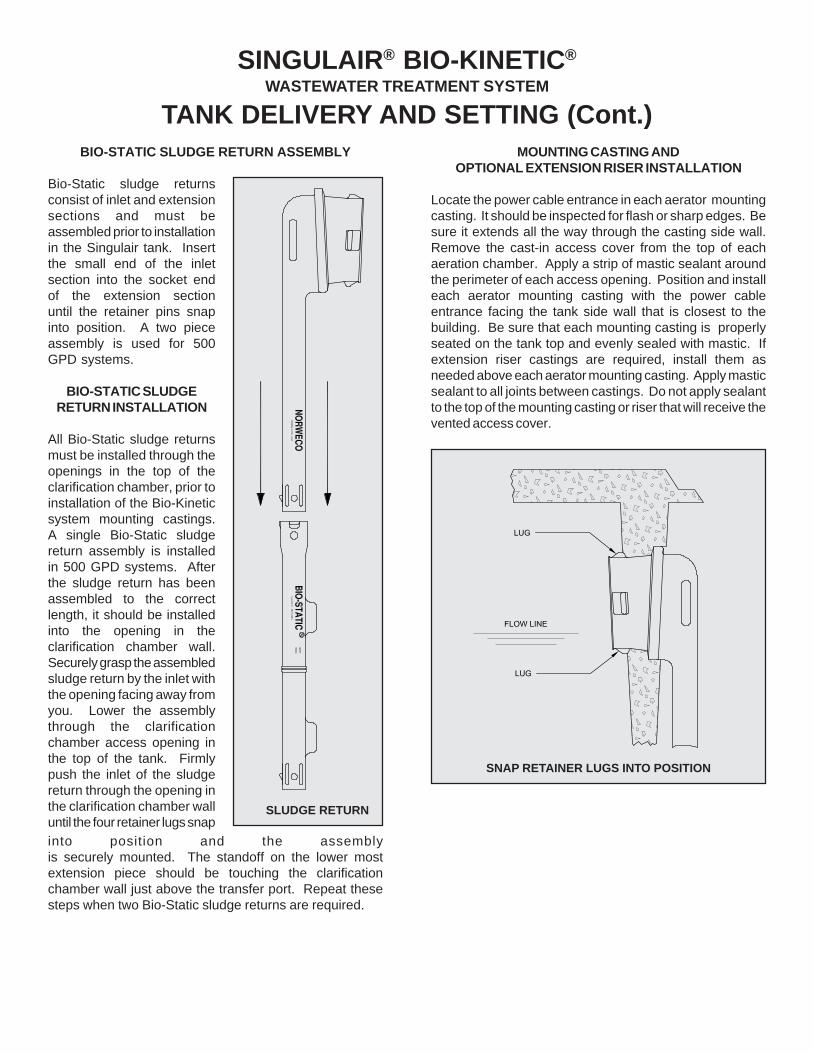
BIO-STATIC SLUDGE RETURN ASSEMBLY
Bio-Static sludge returnsconsist of inlet and extensionsections and must beassembled prior to installationin the Singulair tank. Insertthe small end of the inletsection into the socket endof the extension sectionuntil the retainer pins snapinto position. A two pieceassembly is used for 500GPD systems.
BIO-STATIC SLUDGERETURN INSTALLATION
All Bio-Static sludge returnsmust be installed through theopenings in the top of theclarification chamber, prior toinstallation of the Bio-Kineticsystem mounting castings.A single Bio-Static sludgereturn assembly is installedin 500 GPD systems. Afterthe sludge return has beenassembled to the correctlength, it should be installedinto the opening in theclarification chamber wall.Securely grasp the assembledsludge return by the inlet withthe opening facing away fromyou. Lower the assemblythrough the clarificationchamber access opening inthe top of the tank. Firmlypush the inlet of the sludgereturn through the opening inthe clarification chamber walluntil the four retainer lugs snapinto position and the assemblyis securely mounted. The standoff on the lower mostextension piece should be touching the clarificationchamber wall just above the transfer port. Repeat thesesteps when two Bio-Static sludge returns are required.
MOUNTING CASTING ANDOPTIONAL EXTENSION RISER INSTALLATION
Locate the power cable entrance in each aerator mountingcasting. It should be inspected for flash or sharp edges. Besure it extends all the way through the casting side wall.Remove the cast-in access cover from the top of eachaeration chamber. Apply a strip of mastic sealant aroundthe perimeter of each access opening. Position and installeach aerator mounting casting with the power cableentrance facing the tank side wall that is closest to thebuilding. Be sure that each mounting casting is properlyseated on the tank top and evenly sealed with mastic. Ifextension riser castings are required, install them asneeded above each aerator mounting casting. Apply masticsealant to all joints between castings. Do not apply sealantto the top of the mounting casting or riser that will receive thevented access cover.
SNAP RETAINER LUGS INTO POSITION
TANK DELIVERY AND SETTING (Cont.)
SINGULAIR® BIO-KINETIC®
WASTEWATER TREATMENT SYSTEM
SLUDGE RETURN
MANUFACTURED BYNORWECO, INC.NORWALK, OHIOU.S.A. 44857www.norweco.com
©MMIV NORWECO, INC. NORWALK, OHIO U.S.A.
TANK DELIVERY AND SETTING (Cont.)The pretreatment chamber can be made accessible at gradeor left below grade, as required by local regulationor owner preference. The inspection cover on thepretreatment chamber must at least be developed to withintwelve inches of finished grade. Pretreatment chamberaccess covers should never be vented and should be sealedwith mastic. Be sure all cast-in access opening covers thatare not extended to grade are properly aligned, seated andsecurely in place. Tank covers which have beenreplaced by Bio-Kinetic or aerator mounting castings shouldbe returned to your plant with the delivery truck. Install allcovers for aerator mounting castings, Bio-Kinetic systemmounting castings, risers and inspection ports beforebackfilling begins.
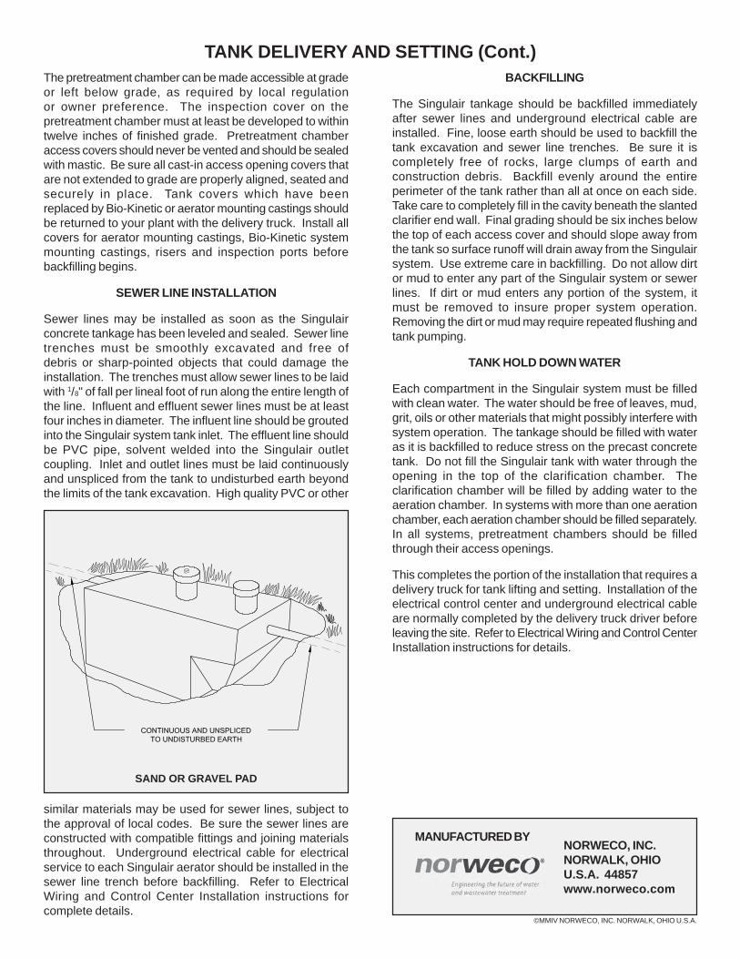
SEWER LINE INSTALLATION
Sewer lines may be installed as soon as the Singulairconcrete tankage has been leveled and sealed. Sewer linetrenches must be smoothly excavated and free ofdebris or sharp-pointed objects that could damage theinstallation. The trenches must allow sewer lines to be laidwith 1/8" of fall per lineal foot of run along the entire length ofthe line. Influent and effluent sewer lines must be at leastfour inches in diameter. The influent line should be groutedinto the Singulair system tank inlet. The effluent line shouldbe PVC pipe, solvent welded into the Singulair outletcoupling. Inlet and outlet lines must be laid continuouslyand unspliced from the tank to undisturbed earth beyondthe limits of the tank excavation. High quality PVC or other
similar materials may be used for sewer lines, subject tothe approval of local codes. Be sure the sewer lines areconstructed with compatible fittings and joining materialsthroughout. Underground electrical cable for electricalservice to each Singulair aerator should be installed in thesewer line trench before backfilling. Refer to ElectricalWiring and Control Center Installation instructions forcomplete details.
BACKFILLING
The Singulair tankage should be backfilled immediatelyafter sewer lines and underground electrical cable areinstalled. Fine, loose earth should be used to backfill thetank excavation and sewer line trenches. Be sure it iscompletely free of rocks, large clumps of earth andconstruction debris. Backfill evenly around the entireperimeter of the tank rather than all at once on each side.Take care to completely fill in the cavity beneath the slantedclarifier end wall. Final grading should be six inches belowthe top of each access cover and should slope away fromthe tank so surface runoff will drain away from the Singulairsystem. Use extreme care in backfilling. Do not allow dirtor mud to enter any part of the Singulair system or sewerlines. If dirt or mud enters any portion of the system, itmust be removed to insure proper system operation.Removing the dirt or mud may require repeated flushing andtank pumping.
TANK HOLD DOWN WATER
Each compartment in the Singulair system must be filledwith clean water. The water should be free of leaves, mud,grit, oils or other materials that might possibly interfere withsystem operation. The tankage should be filled with wateras it is backfilled to reduce stress on the precast concretetank. Do not fill the Singulair tank with water through theopening in the top of the clarification chamber. Theclarification chamber will be filled by adding water to theaeration chamber. In systems with more than one aerationchamber, each aeration chamber should be filled separately.In all systems, pretreatment chambers should be filledthrough their access openings.
This completes the portion of the installation that requires adelivery truck for tank lifting and setting. Installation of theelectrical control center and underground electrical cableare normally completed by the delivery truck driver beforeleaving the site. Refer to Electrical Wiring and Control CenterInstallation instructions for details.
SAND OR GRAVEL PAD
CONTROL CENTER WITH MCD TECHNOLOGY
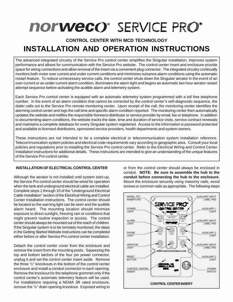
INSTALLATION AND OPERATION INSTRUCTIONSThe advanced integrated circuitry of the Service Pro control center simplifies the Singulair installation, improves systemperformance and allows for communication with the Service Pro website. The control center insert and enclosure providespace for wiring connections and allow removal of the insert via a convenient plug connector. The integrated circuitry continuallymonitors both motor over current and under current conditions and minimizes nuisance alarm conditions using the automaticrestart feature. To reduce unnecessary service calls, the control center shuts down the Singulair aerator in the event of anover current or an under current alarm condition, illuminates the alarm light and begins an automatic two hour aerator restartattempt sequence before activating the audible alarm and telemetry system.
Each Service Pro control center is equipped with an automatic telemetry system programmed with a toll free telephonenumber. In the event of an alarm condition that cannot be corrected by the control center’s self-diagnostic sequence, thedialer calls out to the Service Pro remote monitoring center. Upon receipt of the call, the monitoring center identifies thealarming control center and logs the call time and specific alarm condition reported. The monitoring center then automaticallyupdates the website and notifies the responsible Norweco distributor or service provider by email, fax or telephone. In additionto documenting alarm conditions, the website tracks the date, time and duration of service visits, service contract renewalsand maintains a complete database for every Singulair system registered. Access to the information is password protectedand available to licensed distributors, sponsored service providers, health departments and system owners.
These instructions are not intended to be a complete electrical or telecommunication system installation reference.Telecommunication system policies and electrical code requirements vary according to geographic area. Consult your localpolicies and regulations prior to installing the Service Pro control center. Refer to the Electrical Wiring and Control CenterInstallation instructions for additional details. These instructions are intended to give an understanding of the unique featuresof the Service Pro control center.
INSTALLATION OF ELECTRICAL CONTROL CENTER
Although the aerator is not installed until system start-up,the Service Pro control center should be wired for operationwhen the tank and underground electrical cable are installed.Complete steps 1 through 10 of the “Underground ElectricalCable Installation” section of the Electrical Wiring and ControlCenter Installation instructions. The control center shouldbe located so the warning light can be seen and the audiblealarm heard. The mounting location should minimizeexposure to direct sunlight, freezing rain or conditions thatmight prevent routine inspection or access. The controlcenter should always be mounted out of the reach of children.If the Singulair system is to be remotely monitored, the stepsin the Getting Started Website Instructions can be completedeither before or after Service Pro control center installation.
Detach the control center cover from the enclosure andremove the insert from the mounting posts. Squeezing thetop and bottom latches of the four pin power connector,unplug it and set the control center insert aside. Removethe three 1/2" knockouts in the bottom of the control centerenclosure and install a conduit connector in each opening.Remove the knockout for the telephone grommet only if thecontrol center’s automatic telemetry feature will be used.For installations requiring a NEMA 3R rated enclosure,remove the 1/8" drain opening knockout. Exposed wiring to
or from the control center should always be enclosed inconduit. NOTE: Be sure to assemble the hub to theconduit before connecting the hub to the enclosure.Mount the enclosure securely using masonry nails, woodscrews or common nails as appropriate. The following steps
CONTROL CENTER INSERT
©MMVI NORWECO, INC. NORWALK, OHIO U.S.A.
MANUFACTURED BYNORWECO, INC.NORWALK, OHIOU.S.A. 44857www.norweco.com
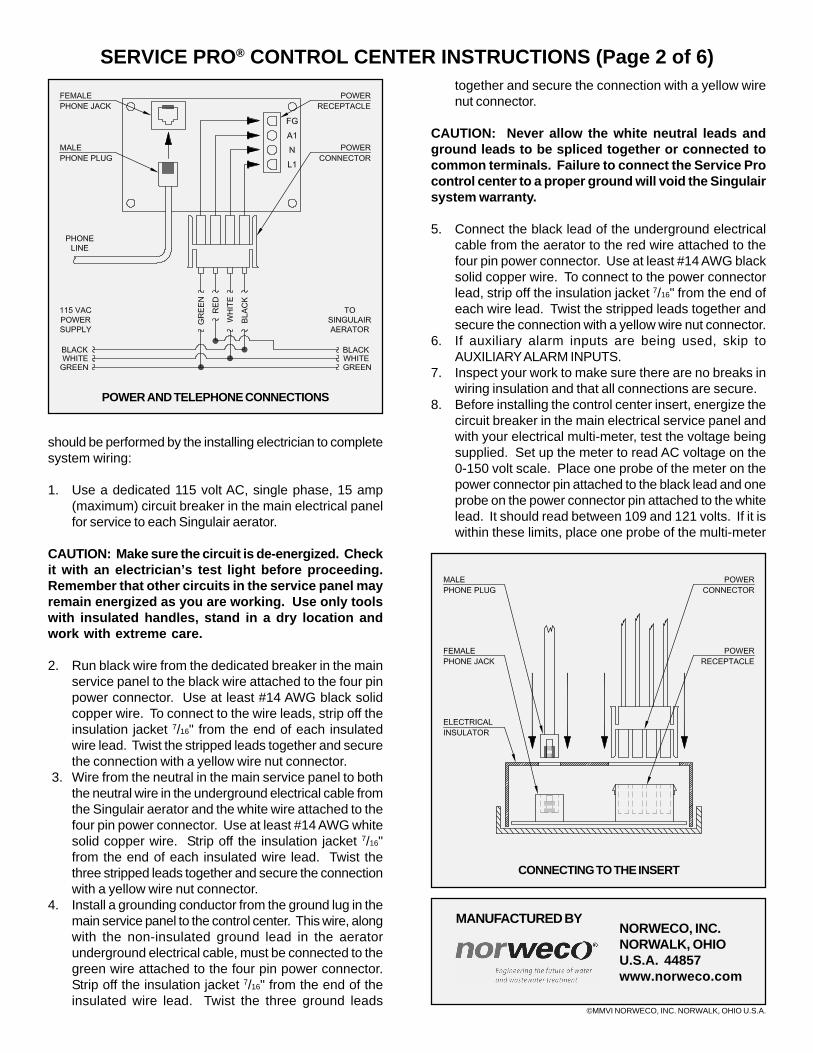
SERVICE PRO® CONTROL CENTER INSTRUCTIONS (Page 2 of 6)together and secure the connection with a yellow wirenut connector.
CAUTION: Never allow the white neutral leads andground leads to be spliced together or connected tocommon terminals. Failure to connect the Service Procontrol center to a proper ground will void the Singulairsystem warranty.
5. Connect the black lead of the underground electricalcable from the aerator to the red wire attached to thefour pin power connector. Use at least #14 AWG blacksolid copper wire. To connect to the power connectorlead, strip off the insulation jacket 7/16" from the end ofeach wire lead. Twist the stripped leads together andsecure the connection with a yellow wire nut connector.
6. If auxiliary alarm inputs are being used, skip toAUXILIARY ALARM INPUTS.
7. Inspect your work to make sure there are no breaks inwiring insulation and that all connections are secure.
8. Before installing the control center insert, energize thecircuit breaker in the main electrical service panel andwith your electrical multi-meter, test the voltage beingsupplied. Set up the meter to read AC voltage on the0-150 volt scale. Place one probe of the meter on thepower connector pin attached to the black lead and oneprobe on the power connector pin attached to the whitelead. It should read between 109 and 121 volts. If it iswithin these limits, place one probe of the multi-meter
should be performed by the installing electrician to completesystem wiring:
1. Use a dedicated 115 volt AC, single phase, 15 amp(maximum) circuit breaker in the main electrical panelfor service to each Singulair aerator.
CAUTION: Make sure the circuit is de-energized. Checkit with an electrician’s test light before proceeding.Remember that other circuits in the service panel mayremain energized as you are working. Use only toolswith insulated handles, stand in a dry location andwork with extreme care.
2. Run black wire from the dedicated breaker in the mainservice panel to the black wire attached to the four pinpower connector. Use at least #14 AWG black solidcopper wire. To connect to the wire leads, strip off theinsulation jacket 7/16" from the end of each insulatedwire lead. Twist the stripped leads together and securethe connection with a yellow wire nut connector.
3. Wire from the neutral in the main service panel to boththe neutral wire in the underground electrical cable fromthe Singulair aerator and the white wire attached to thefour pin power connector. Use at least #14 AWG whitesolid copper wire. Strip off the insulation jacket 7/16"from the end of each insulated wire lead. Twist thethree stripped leads together and secure the connectionwith a yellow wire nut connector.
4. Install a grounding conductor from the ground lug in themain service panel to the control center. This wire, alongwith the non-insulated ground lead in the aeratorunderground electrical cable, must be connected to thegreen wire attached to the four pin power connector.Strip off the insulation jacket 7/16" from the end of theinsulated wire lead. Twist the three ground leads
POWER AND TELEPHONE CONNECTIONS
CONNECTING TO THE INSERT
INSTALLATION AND OPERATION (Page 3 of 6)
SERVICE PRO®
CONTROL CENTER WITH MCD TECHNOLOGY
on the power connector pin attached to the red lead andone probe on the power connector pin attached to thewhite lead. The meter should read 0 volts. Once thesereadings are confirmed, place the dedicated circuitbreaker in the main service panel in the “off” position.The conduit openings in the control center must now besealed using duct seal. IMPORTANT: The conduitopenings must be sealed to prevent corrosive gas fromentering the control center enclosure and causing a fireor explosion. Failure to properly seal all conduit openingswill void the Singulair system warranty.
9. Close the insulator and plug the four pin power connectorinto the control center insert until the latches are secure.Snap the insert into position.
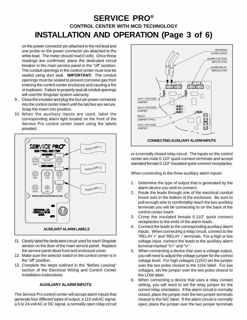
10. When the auxiliary inputs are used, label thecorresponding alarm light located on the front of theService Pro control center insert using the labelsprovided.
11. Clearly label the dedicated circuit used for each Singulairaerator on the door of the main service panel. Replacethe service panel dead front and enclosure cover.
12. Make sure the selector switch in the control center is inthe “off” position.
13. Complete the steps outlined in the “Before Leaving”section of the Electrical Wiring and Control CenterInstallation instructions.
AUXILIARY ALARM INPUTS
The Service Pro control center will accept alarm inputs thatgenerate four different types of output: a 115 volt AC signal,a 5 to 24 volt AC or DC signal, a normally open relay circuit
or a normally closed relay circuit. The inputs on the controlcenter are male 0.110" quick connect terminals and acceptstandard female 0.110" insulated quick connect receptacles.
When connecting to the three auxiliary alarm inputs:
1. Determine the type of output that is generated by thealarm device you wish to connect.
2. Route the leads through one of the electrical conduitknock outs in the bottom of the enclosure. Be sure topull enough wire to comfortably reach the two auxiliaryterminals you will be connecting to on the back of thecontrol center insert.
3. Crimp the insulated female 0.110" quick connectreceptacles to the ends of the alarm leads.
4. Connect the leads to the corresponding auxiliary alarminputs. When connecting a relay circuit, connect to the“RELAY +” and “RELAY -” terminals. For a high or lowvoltage input, connect the leads to the auxiliary alarmterminal marked “V+” and “V-”.
5. When connecting a device that uses a voltage output,you will need to adjust the voltage jumper for the correctvoltage level. For high voltages (115V) set the jumperover the two poles closest to the 115V label. For lowvoltages, set the jumper over the two poles closest tothe LOW label.
6. When connecting a device that uses a relay contactsetting, you will need to set the relay jumper for thecorrect relay orientation. If the alarm circuit is normallyclosed, place the jumper over the two jumper terminalsclosest to the N/C label. If the alarm circuit is normallyopen, place the jumper over the two jumper terminals
CONNECTING AUXILIARY ALARM INPUTS
AUXILIARY ALARM LABELS
©MMVI NORWECO, INC. NORWALK, OHIO U.S.A.
MANUFACTURED BYNORWECO, INC.NORWALK, OHIOU.S.A. 44857www.norweco.com
SERVICE PRO® CONTROL CENTER INSTRUCTIONS (Page 4 of 6)closest to the N/O label (see CONNECTING AUXILIARYALARM INPUTS on Page 3 for reference).
TELEPHONE LINE INSTALLATION REQUIREMENTS
In order to utilize the telemetry system, a telephone cablemust be installed between the control center and thetelephone service box. This cable must be unspliced fromthe telephone box to the control center enclosure.Telecommunication systems and equipment used to supplyservice vary. Before installing the telephone wire, familiarizeyourself with the equipment and policies of the local telephoneservice provider. The Service Pro control center is compatiblewith digital telephone service as long as it is installeddownstream of the digital /analog converter. The followingsteps must be performed to complete system wiring. If atelephone cable is not available, one will need to be installedusing the connector and methods specified by the telephoneservice provider.
1. Make sure the dedicated circuit breaker in the mainservice panel is in the “off” position. Using the grommetprovided, run the telephone cable into the bottom of thecontrol center enclosure.
2. Remove the insert and insert the telephone plug throughthe opening in the electrical insulator on the controlcenter insert and plug into the female phone jackprovided. Connect the other end of the phone line to theexisting telephone system.
3. Snap the control center insert into position. Close thecontrol center cover and secure it with a Norweco tamperevident seal.
SERVICE PRO REGISTRATION
Refer to the Getting Started Website Instructions for stepby step instructions on registering a new installation on theService Pro website. If you do not have access to theinternet, fill in all information fields on the registration cardthat came with the control center and place the card in themail after affixing proper postage. The information isnecessary to register the Singulair system atwww.servicepromcd.com. In the Notification Method field,indicate your preferences for notification should an alarmcondition occur. Your choices are email, fax or telephonecall (an additional fee applies for telephone notification).Return the registration form to Norweco, and the informationwill be entered into the monitoring center for you. You willthen be provided with Service Pro website information,including a username and password. The username andpassword will allow access to the Service Pro website inorder to view all operating information on each Service Procontrol center installation.
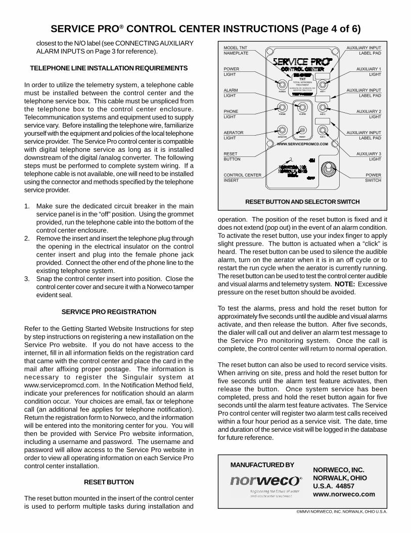
RESET BUTTON
The reset button mounted in the insert of the control centeris used to perform multiple tasks during installation and
operation. The position of the reset button is fixed and itdoes not extend (pop out) in the event of an alarm condition.To activate the reset button, use your index finger to applyslight pressure. The button is actuated when a “click” isheard. The reset button can be used to silence the audiblealarm, turn on the aerator when it is in an off cycle or torestart the run cycle when the aerator is currently running.The reset button can be used to test the control center audibleand visual alarms and telemetry system. NOTE: Excessivepressure on the reset button should be avoided.
To test the alarms, press and hold the reset button forapproximately five seconds until the audible and visual alarmsactivate, and then release the button. After five seconds,the dialer will call out and deliver an alarm test message tothe Service Pro monitoring system. Once the call iscomplete, the control center will return to normal operation.
The reset button can also be used to record service visits.When arriving on site, press and hold the reset button forfive seconds until the alarm test feature activates, thenrelease the button. Once system service has beencompleted, press and hold the reset button again for fiveseconds until the alarm test feature activates. The ServicePro control center will register two alarm test calls receivedwithin a four hour period as a service visit. The date, timeand duration of the service visit will be logged in the databasefor future reference.
RESET BUTTON AND SELECTOR SWITCH
INSTALLATION AND OPERATION (Page 5 of 6)
SERVICE PRO®
CONTROL CENTER WITH MCD TECHNOLOGY
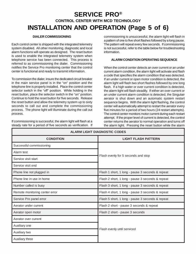
commissioning is unsuccessful, the alarm light will flash ina pattern of one to five short flashes followed by a long pause.The pattern will repeat every few seconds. If commissioningis not successful, refer to the table below for troubleshootinginformation.
ALARM CONDITION OPERATING SEQUENCE
When the control center detects an over current or an undercurrent alarm condition, the alarm light will activate and flasha code that specifies the alarm condition that was detected.If an under current or open motor condition is detected, thealarm light will flash two short flashes followed by one longflash. If a high water or over current condition is detected,the alarm light will flash steadily. If either an over current oran under current alarm condition is detected, the Singulairaerator is shut down and an automatic system restartsequence begins. With the alarm light flashing, the controlcenter will automatically attempt to restart the aerator everyfive minutes for a period of two hours (24 restart attempts).The control center monitors motor current during each restartattempt. If the proper level of current is detected, the controlcenter returns the aerator to normal operation and turns offthe alarm light. Pressing the reset button while the alarm
DIALER COMMISSIONING
Each control center is shipped with the integrated telemetrysystem disabled. All other monitoring, diagnostic and localalarm functions will operate as designed. The reset buttonis used to enable the integrated telemetry system whentelephone service has been connected. This process isreferred to as commissioning the dialer. Commissioningnotifies the Service Pro monitoring center that the controlcenter is functional and ready to transmit information.
To commission the dialer, insure the dedicated circuit breakerin the main service panel is in the “on” position and thetelephone line is properly installed. Place the control centerselector switch in the “off” position. While holding in thereset button, place the selector switch in the “on” position.Continue to hold the reset button for five seconds. Releasethe reset button and allow the telemetry system up to sixtyseconds to call out and complete the commissioningprocess. The phone light will illuminate during the call outprocess.
If commissioning is successful, the alarm light will flash at asteady rate for a period of five seconds as verification. If
SEDOCCITSONGAIDTHGILMRALA
NOITIDNOC NRETTAPHSALFTHGIL
gninoissimmoclufsseccuS
potsdnasdnoces5rofylnevehsalFtsetmralA
tratstisivecivreS
dnetisivecivreS
nideggulptonenilenohP taeper&sdnoces3esuap-gnol1,trohs1hsalF
emohniesunienilenohP taeper&sdnoces3esuap-gnol1,trohs2hsalF
ysubsidellacrebmuN taeper&sdnoces3esuap-gnol1,trohs3hsalF
rorreretnecgnirotinometomeR taeper&sdnoces3esuap-gnol1,trohs4hsalF
rorrelenaporPecivreS taeper&sdnoces3esuap-gnol1,trohs5hsalF
tnerrucrednurotareA taeper&sdnoces3esuap-trohs2hsalF
rotomneporotareA sdnoces3esuap-trohs2hsalF
tnerrucrevorotareA
decivreslitnuylnevehsalFenoyrailixuA
owtyrailixuA
eerhtyrailixuA
©MMVI NORWECO, INC. NORWALK, OHIO U.S.A.
MANUFACTURED BYNORWECO, INC.NORWALK, OHIOU.S.A. 44857www.norweco.com
SERVICE PRO® CONTROL CENTER INSTRUCTIONS (Page 6 of 6)operations of the equipment. If this happens the telephonecompany will provide advance notice in order for you to makenecessary modifications to maintain uninterrupted service.
If trouble is experienced with the Service Pro control center,for repair or warranty information, please contact Norweco,Inc. If the equipment is causing harm to the telephonenetwork, the telephone company may request that youdisconnect the equipment until the problem is resolved.
SERVICE PRO WEBSITE
The telemetry system that comes standard with every ServicePro control center is engineered to interface with the ServicePro monitoring center. The Service Pro monitoring centerallows the homeowner, service provider, licensed Norwecodistributor and authorized regulatory entities access toSingulair wastewater treatment system records online.Records generated by the Service Pro control centerthroughout the life of the Singulair system (heartbeat record,alarm conditions, service records) can then be accessed atwww.servicepromcd.com.
When a monitoring contract is initiated, the user will beissued a password that will allow them website access tothe information pertaining to their system. Once a ServicePro control center has been installed and the homeownerhas decided to use the Service Pro website, please refer tothe Getting Started Website Instructions on how to proceedwith setting up the user account. A control center can becommissioned either before or after the new account hasbeen formally registered with the Service Pro monitoringcenter. However, if the commissioning step is performedfirst, the registration of the new account must be completedwithin thirty (30) days of commissioning. Additionally, theService Pro monitoring service agreement must be signedand returned to Norweco before system monitoring will begin.
light is flashing causes the control center to attempt to restartthe aerator and counts toward the 24 restart attempts. Ifthe aerator does not restart after 24 attempts, the audiblealarm and the alarm light activate.
After both audible and visual alarms are activated, press thereset button and the control center will attempt to restartthe aerator again. If the proper current level is not detected,the audible alarm beeps three times, then silences. Thealarm light continues to flash and the control center interruptspower to the aerator. If the alarm condition is not correctedand the control center reset after 48 hours, the audible alarmwill automatically reactivate.
If an auxiliary alarm condition is detected, the audible alarmand the corresponding auxiliary alarm light will activate.
If the telemetry system on the Service Pro control centerhas been commissioned, the system will then attempt tocall out after a five minute delay and deliver an alarm message.The system will call the Service Pro monitoring center every48 hours until the alarm condition is corrected and the controlcenter is reset. The Service Pro control center usesadvanced diagnostic technology to monitor the Singulairsystem for proper operation. In the event an alarm conditionis encountered, the control center will display a series offlashes from the alarm light located in the center of the controlpanel (refer to the Alarm Light Diagnostic Codes chart onPage 5 for further reference).
SYSTEM HEARTBEAT FEATURE
The Service Pro control center contains a system heartbeatfeature that will call out every 30 days to inform themonitoring center that the Singulair system is functioningas designed. If the heartbeat call is not received, themonitoring center will notify the distributor or service providerthat service is required at that location.
FCC COMPLIANCE
This equipment complies with Part 68 of the FCC rules andthe requirements adopted by the ACTA. The label on theinside of the control center cover contains, among otherinformation, a product identifier in the formatUS:NK1MM00BLTS00700. If requested, this number mustbe provided to the telephone company.
If the Service Pro control center causes harm to the telephonenetwork, the telephone company will notify you in advancethat temporary discontinuance of service may be required.But if advance notice isn’t practical, the telephone companywill notify the customer as soon as possible. Also, you willbe advised of your right to file a complaint with the FCC ifyou believe it is necessary.
The telephone company may make changes in its facilities,equipment, operations or procedures that could affect the
INTEGRATED SYSTEM CONTROLS
ELECTRICAL WIRING & CONTROL CENTER INSTALLATION
UNDERGROUND ELECTRICAL CABLE INSTALLATION
1. A separate underground electrical service cable mustbe installed for each aerator within the Singulair system.Each cable must be UL or CSA approved, type UF,#14/2 AWG minimum and must have a full-size centerground. Larger cable is required if the undergroundservice needs to be run more than 80 feet. A separateunderground electrical service cable must also beinstalled for each effluent pump and float switch. Consultyour electrician for details on pump and float cable sizingbased on the specific pumps used and the length ofthe cable run. NOTE: Each float switch cable (otherthan alarm float switch cables) may carry the fullelectrical load of the pump and must be sized accordingto the same requirements as the pump power cord.
2. Each underground cable must be continuous andunspliced from the integrated control center to eachaerator, pump and float switch.
3. Underground cable must be protected in conduit anytimethe cable path passes directly across a tank orunderground structure.
4. Uncoil the electrical service cables into the excavationinfluent sewer line trench. Extend the aerator cable tothe aerator mounting casting and the pump and floatelectrical service cables to the pump station chamber.Leave sufficient slack in the cables so that they will notbe stressed or pulled tight during backfill or settling.
5. All underground electrical cables should have at leasttwo feet of earth cover. If the proposed finish grade willnot permit at least two feet of earth coverage, all cablesshould be installed from the control center to theappropriate component using an approved conduit .
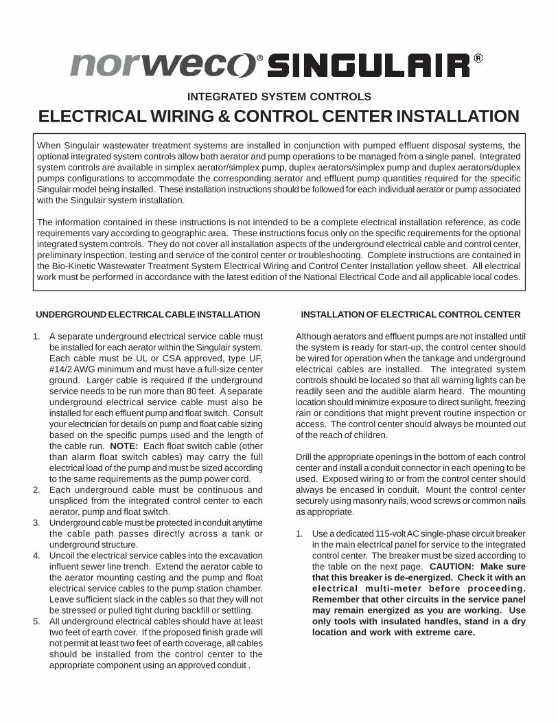
When Singulair wastewater treatment systems are installed in conjunction with pumped effluent disposal systems, theoptional integrated system controls allow both aerator and pump operations to be managed from a single panel. Integratedsystem controls are available in simplex aerator/simplex pump, duplex aerators/simplex pump and duplex aerators/duplexpumps configurations to accommodate the corresponding aerator and effluent pump quantities required for the specificSingulair model being installed. These installation instructions should be followed for each individual aerator or pump associatedwith the Singulair system installation.
The information contained in these instructions is not intended to be a complete electrical installation reference, as coderequirements vary according to geographic area. These instructions focus only on the specific requirements for the optionalintegrated system controls. They do not cover all installation aspects of the underground electrical cable and control center,preliminary inspection, testing and service of the control center or troubleshooting. Complete instructions are contained inthe Bio-Kinetic Wastewater Treatment System Electrical Wiring and Control Center Installation yellow sheet. All electricalwork must be performed in accordance with the latest edition of the National Electrical Code and all applicable local codes.
INSTALLATION OF ELECTRICAL CONTROL CENTER
Although aerators and effluent pumps are not installed untilthe system is ready for start-up, the control center shouldbe wired for operation when the tankage and undergroundelectrical cables are installed. The integrated systemcontrols should be located so that all warning lights can bereadily seen and the audible alarm heard. The mountinglocation should minimize exposure to direct sunlight, freezingrain or conditions that might prevent routine inspection oraccess. The control center should always be mounted outof the reach of children.
Drill the appropriate openings in the bottom of each controlcenter and install a conduit connector in each opening to beused. Exposed wiring to or from the control center shouldalways be encased in conduit. Mount the control centersecurely using masonry nails, wood screws or common nailsas appropriate.
1. Use a dedicated 115-volt AC single-phase circuit breakerin the main electrical panel for service to the integratedcontrol center. The breaker must be sized according tothe table on the next page. CAUTION: Make surethat this breaker is de-energized. Check it with anelectrical multi-meter before proceeding.Remember that other circuits in the service panelmay remain energized as you are working. Useonly tools with insulated handles, stand in a drylocation and work with extreme care.
MANUFACTURED BY
©MMIV NORWECO, INC. NORWALK, OHIO U.S.A.
NORWECO, INC.NORWALK, OHIOU.S.A. 44857
ELECTRICAL WIRING AND CONTROL CENTER INSTALLATION (Cont.)
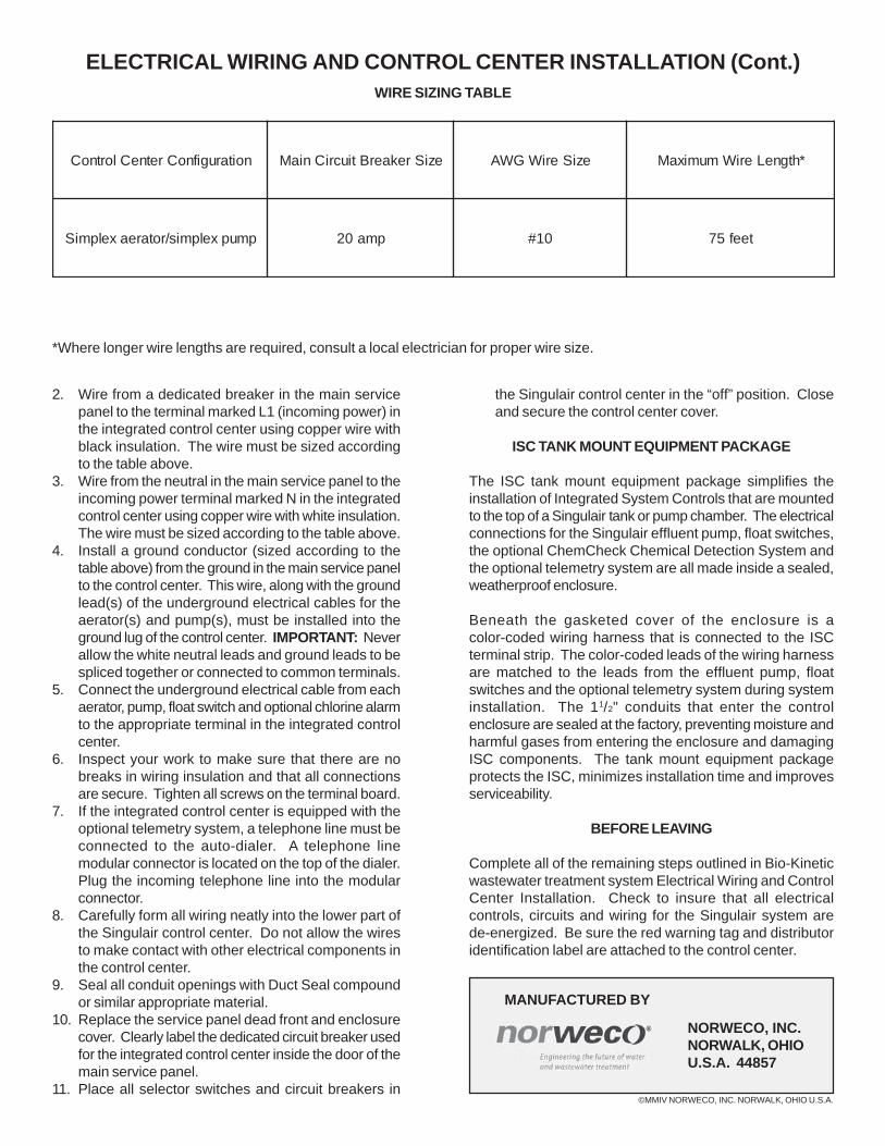
noitarugifnoCretneClortnoC eziSrekaerBtiucriCniaM eziSeriWGWA *htgneLeriWmumixaM
pmupxelpmis/rotareaxelpmiS pma02 01# teef57
2. Wire from a dedicated breaker in the main servicepanel to the terminal marked L1 (incoming power) inthe integrated control center using copper wire withblack insulation. The wire must be sized accordingto the table above.
3. Wire from the neutral in the main service panel to theincoming power terminal marked N in the integratedcontrol center using copper wire with white insulation.The wire must be sized according to the table above.
4. Install a ground conductor (sized according to thetable above) from the ground in the main service panelto the control center. This wire, along with the groundlead(s) of the underground electrical cables for theaerator(s) and pump(s), must be installed into theground lug of the control center. IMPORTANT: Neverallow the white neutral leads and ground leads to bespliced together or connected to common terminals.
5. Connect the underground electrical cable from eachaerator, pump, float switch and optional chlorine alarmto the appropriate terminal in the integrated controlcenter.
6. Inspect your work to make sure that there are nobreaks in wiring insulation and that all connectionsare secure. Tighten all screws on the terminal board.
7. If the integrated control center is equipped with theoptional telemetry system, a telephone line must beconnected to the auto-dialer. A telephone linemodular connector is located on the top of the dialer.Plug the incoming telephone line into the modularconnector.
8. Carefully form all wiring neatly into the lower part ofthe Singulair control center. Do not allow the wiresto make contact with other electrical components inthe control center.
9. Seal all conduit openings with Duct Seal compoundor similar appropriate material.
10. Replace the service panel dead front and enclosurecover. Clearly label the dedicated circuit breaker usedfor the integrated control center inside the door of themain service panel.
11. Place all selector switches and circuit breakers in
the Singulair control center in the “off” position. Closeand secure the control center cover.
ISC TANK MOUNT EQUIPMENT PACKAGE
The ISC tank mount equipment package simplifies theinstallation of Integrated System Controls that are mountedto the top of a Singulair tank or pump chamber. The electricalconnections for the Singulair effluent pump, float switches,the optional ChemCheck Chemical Detection System andthe optional telemetry system are all made inside a sealed,weatherproof enclosure.
Beneath the gasketed cover of the enclosure is acolor-coded wiring harness that is connected to the ISCterminal strip. The color-coded leads of the wiring harnessare matched to the leads from the effluent pump, floatswitches and the optional telemetry system during systeminstallation. The 11/2" conduits that enter the controlenclosure are sealed at the factory, preventing moisture andharmful gases from entering the enclosure and damagingISC components. The tank mount equipment packageprotects the ISC, minimizes installation time and improvesserviceability.
BEFORE LEAVING
Complete all of the remaining steps outlined in Bio-Kineticwastewater treatment system Electrical Wiring and ControlCenter Installation. Check to insure that all electricalcontrols, circuits and wiring for the Singulair system arede-energized. Be sure the red warning tag and distributoridentification label are attached to the control center.
*Where longer wire lengths are required, consult a local electrician for proper wire size.
WIRE SIZING TABLE
BIO-KINETIC® WASTEWATER TREATMENT SYSTEM
AERATOR INSTALLATION
Installation of the aerator and Bio-Kinetic system should take place when the Singulair system is ready for start-up. Refer tothe Bio-Kinetic System Installation instructions for additional details. Your delivery truck driver should have instructed thecontractor or owner to contact your office and make arrangements for equipment installation to coincide with occupancy andsanitary sewer use. Review your Singulair tank setting records weekly to insure that you do not have equipment installationsthat are overdue. If you suspect that adequate time has passed for system start-up and you have not yet heard from theowners, contact them to schedule equipment installation. For Singulair Bio-Kinetic wastewater treatment systems requiringmore than one aerator installation, follow these instructions for each aerator to be installed.
PRE-INSTALLATION CHECKLIST
✓ The installer should have accurate directions to the facility and a list of service inspections due at other installations inthe vicinity.
✓ The service vehicle should carry the Bio-Kinetic Tool Kaddy fully stocked with tools, spare parts and test equipment foruse during installation.
✓ Someone should be present at the location to allow installer access to the control center and electrical service panel.✓ The main electrical service panel wiring must be complete so each aerator may be started-up and tested.✓ All chambers of the Singulair tankage should be full to the flow line.✓ A Bio-Static sludge return should have been installed in each opening in the aeration/clarification chamber wall.✓ The installer must have the proper model and quantity of aerators for the installation.✓ The serial number on each aerator must match the service and warranty record card.
AERATOR START-UP PROCEDURE
When you arrive on site, introduce yourself to the owner andask to see the main electrical service panel and Singulaircontrol center. Be certain each circuit for the Singulairsystem in the main electrical service panel isde-energized and that the selector switch in the Singulaircontrol center is placed in the “off” position.Explain to the owner that you will be installing the aerator inthe tank and you will need access to the main electricalservice panel for system start-up after the aerator has beeninstalled. Carry the aerator in its shipping carton to the tanksite. Place the Singulair Bio-Kinetic Tool Kaddy nearby foreasy access to tools and test equipment. Remove the ventedcover from the aerator mounting casting. Carefully removethe aspirator shaft from the shipping carton. Do not bumpor bend the aspirator shaft. Lay the shaft on the ventedcover. Grip the outside bottom of the shipping carton withyour feet and lift the aerator to remove it. Lay the aerator onits side with the brackets resting on the vented cover nearthe aerator mounting casting. Uncoil the undergroundelectrical service cable from inside the aerator mountingcasting and extend it out of the casting. Test the exposedleads with the electrical multi-meter from the Tool Kaddybefore proceeding. The circuit should not be energized andvoltage should not be evident when the leads are tested withthe multi-meter.
WIRING THE ELECTRICAL CONNECTOR
The moisture resistant electrical connector must beproperly wired to insure system operation and protectcomponents. Carefully follow these steps to completelywire the electrical connector:
1. Uncouple the two halves of the electrical connector onthe Singulair aerator. Unscrew the three captive stainlesssteel screws from the face of the female half of theassembly. They will stay in the body of the receptacle.Lift out the rigid internal receptacle body.
2. Unscrew the compression nut on the strain reliefconnector assembly at the small end of the female halfof the connector. Do not misplace the compressionring. Insert the electrical service cable through thecompression nut, compression ring and neoprenegrommet, which is contained in the molded plastic sleeveof the female connector.
3. Strip the outer insulation back 11/4" on the undergroundelectrical service cable and expose the three individualleads. Use extreme care to be sure the insulationjackets on the individual black and white leads are notscarred or damaged while stripping the outer jacket.Check them carefully. If even slight damage is noticed,cut off the end of the cable just below your work andbegin again.
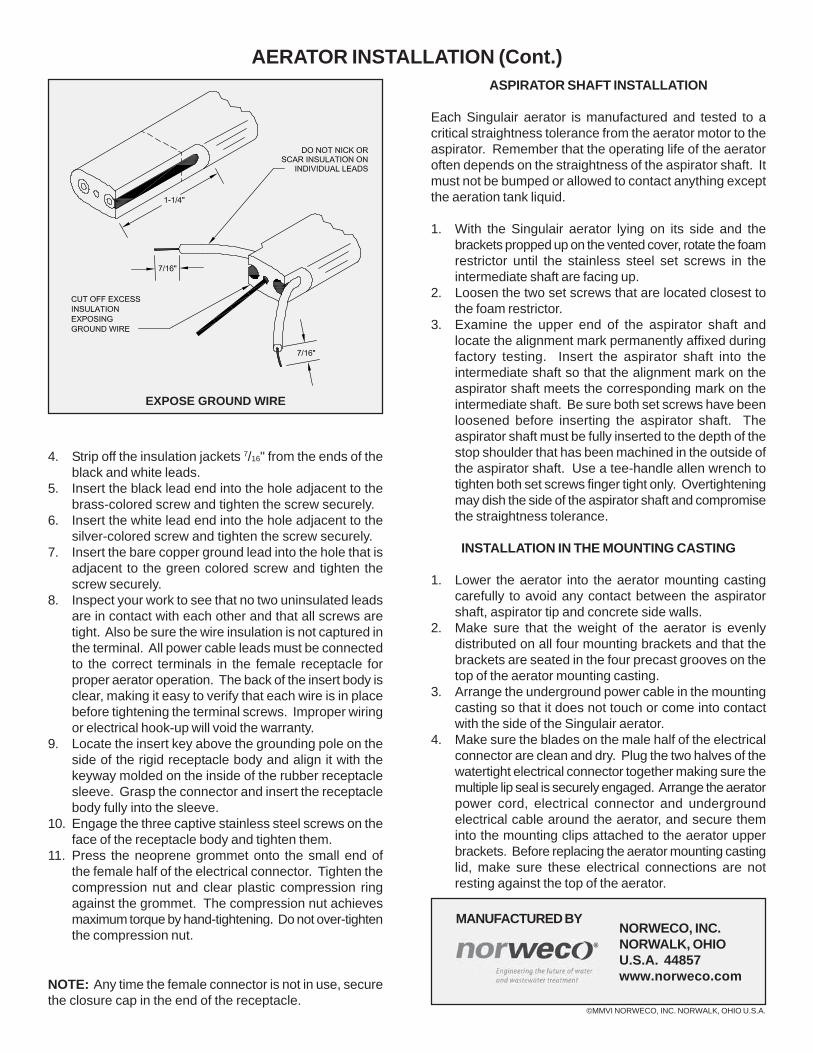
©MMVI NORWECO, INC. NORWALK, OHIO U.S.A.
MANUFACTURED BYNORWECO, INC.NORWALK, OHIOU.S.A. 44857www.norweco.com
AERATOR INSTALLATION (Cont.)ASPIRATOR SHAFT INSTALLATION
Each Singulair aerator is manufactured and tested to acritical straightness tolerance from the aerator motor to theaspirator. Remember that the operating life of the aeratoroften depends on the straightness of the aspirator shaft. Itmust not be bumped or allowed to contact anything exceptthe aeration tank liquid.
1. With the Singulair aerator lying on its side and thebrackets propped up on the vented cover, rotate the foamrestrictor until the stainless steel set screws in theintermediate shaft are facing up.
2. Loosen the two set screws that are located closest tothe foam restrictor.
3. Examine the upper end of the aspirator shaft andlocate the alignment mark permanently affixed duringfactory testing. Insert the aspirator shaft into theintermediate shaft so that the alignment mark on theaspirator shaft meets the corresponding mark on theintermediate shaft. Be sure both set screws have beenloosened before inserting the aspirator shaft. Theaspirator shaft must be fully inserted to the depth of thestop shoulder that has been machined in the outside ofthe aspirator shaft. Use a tee-handle allen wrench totighten both set screws finger tight only. Overtighteningmay dish the side of the aspirator shaft and compromisethe straightness tolerance.
INSTALLATION IN THE MOUNTING CASTING
1. Lower the aerator into the aerator mounting castingcarefully to avoid any contact between the aspiratorshaft, aspirator tip and concrete side walls.
2. Make sure that the weight of the aerator is evenlydistributed on all four mounting brackets and that thebrackets are seated in the four precast grooves on thetop of the aerator mounting casting.
3. Arrange the underground power cable in the mountingcasting so that it does not touch or come into contactwith the side of the Singulair aerator.
4. Make sure the blades on the male half of the electricalconnector are clean and dry. Plug the two halves of thewatertight electrical connector together making sure themultiple lip seal is securely engaged. Arrange the aeratorpower cord, electrical connector and undergroundelectrical cable around the aerator, and secure theminto the mounting clips attached to the aerator upperbrackets. Before replacing the aerator mounting castinglid, make sure these electrical connections are notresting against the top of the aerator.
4. Strip off the insulation jackets 7/16" from the ends of theblack and white leads.
5. Insert the black lead end into the hole adjacent to thebrass-colored screw and tighten the screw securely.
6. Insert the white lead end into the hole adjacent to thesilver-colored screw and tighten the screw securely.
7. Insert the bare copper ground lead into the hole that isadjacent to the green colored screw and tighten thescrew securely.
8. Inspect your work to see that no two uninsulated leadsare in contact with each other and that all screws aretight. Also be sure the wire insulation is not captured inthe terminal. All power cable leads must be connectedto the correct terminals in the female receptacle forproper aerator operation. The back of the insert body isclear, making it easy to verify that each wire is in placebefore tightening the terminal screws. Improper wiringor electrical hook-up will void the warranty.
9. Locate the insert key above the grounding pole on theside of the rigid receptacle body and align it with thekeyway molded on the inside of the rubber receptaclesleeve. Grasp the connector and insert the receptaclebody fully into the sleeve.
10. Engage the three captive stainless steel screws on theface of the receptacle body and tighten them.
11. Press the neoprene grommet onto the small end ofthe female half of the electrical connector. Tighten thecompression nut and clear plastic compression ringagainst the grommet. The compression nut achievesmaximum torque by hand-tightening. Do not over-tightenthe compression nut.
NOTE: Any time the female connector is not in use, securethe closure cap in the end of the receptacle.
EXPOSE GROUND WIRE
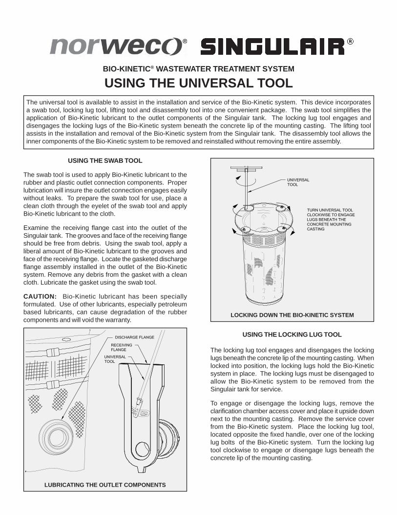
BIO-KINETIC® WASTEWATER TREATMENT SYSTEM
USING THE UNIVERSAL TOOLThe universal tool is available to assist in the installation and service of the Bio-Kinetic system. This device incorporatesa swab tool, locking lug tool, lifting tool and disassembly tool into one convenient package. The swab tool simplifies theapplication of Bio-Kinetic lubricant to the outlet components of the Singulair tank. The locking lug tool engages anddisengages the locking lugs of the Bio-Kinetic system beneath the concrete lip of the mounting casting. The lifting toolassists in the installation and removal of the Bio-Kinetic system from the Singulair tank. The disassembly tool allows theinner components of the Bio-Kinetic system to be removed and reinstalled without removing the entire assembly.
USING THE SWAB TOOL
The swab tool is used to apply Bio-Kinetic lubricant to therubber and plastic outlet connection components. Properlubrication will insure the outlet connection engages easilywithout leaks. To prepare the swab tool for use, place aclean cloth through the eyelet of the swab tool and applyBio-Kinetic lubricant to the cloth.
Examine the receiving flange cast into the outlet of theSingulair tank. The grooves and face of the receiving flangeshould be free from debris. Using the swab tool, apply aliberal amount of Bio-Kinetic lubricant to the grooves andface of the receiving flange. Locate the gasketed dischargeflange assembly installed in the outlet of the Bio-Kineticsystem. Remove any debris from the gasket with a cleancloth. Lubricate the gasket using the swab tool.
CAUTION: Bio-Kinetic lubricant has been speciallyformulated. Use of other lubricants, especially petroleumbased lubricants, can cause degradation of the rubbercomponents and will void the warranty.
USING THE LOCKING LUG TOOL
The locking lug tool engages and disengages the lockinglugs beneath the concrete lip of the mounting casting. Whenlocked into position, the locking lugs hold the Bio-Kineticsystem in place. The locking lugs must be disengaged toallow the Bio-Kinetic system to be removed from theSingulair tank for service.
To engage or disengage the locking lugs, remove theclarification chamber access cover and place it upside downnext to the mounting casting. Remove the service coverfrom the Bio-Kinetic system. Place the locking lug tool,located opposite the fixed handle, over one of the lockinglug bolts of the Bio-Kinetic system. Turn the locking lugtool clockwise to engage or disengage lugs beneath theconcrete lip of the mounting casting.
LUBRICATING THE OUTLET COMPONENTS
LOCKING DOWN THE BIO-KINETIC SYSTEM
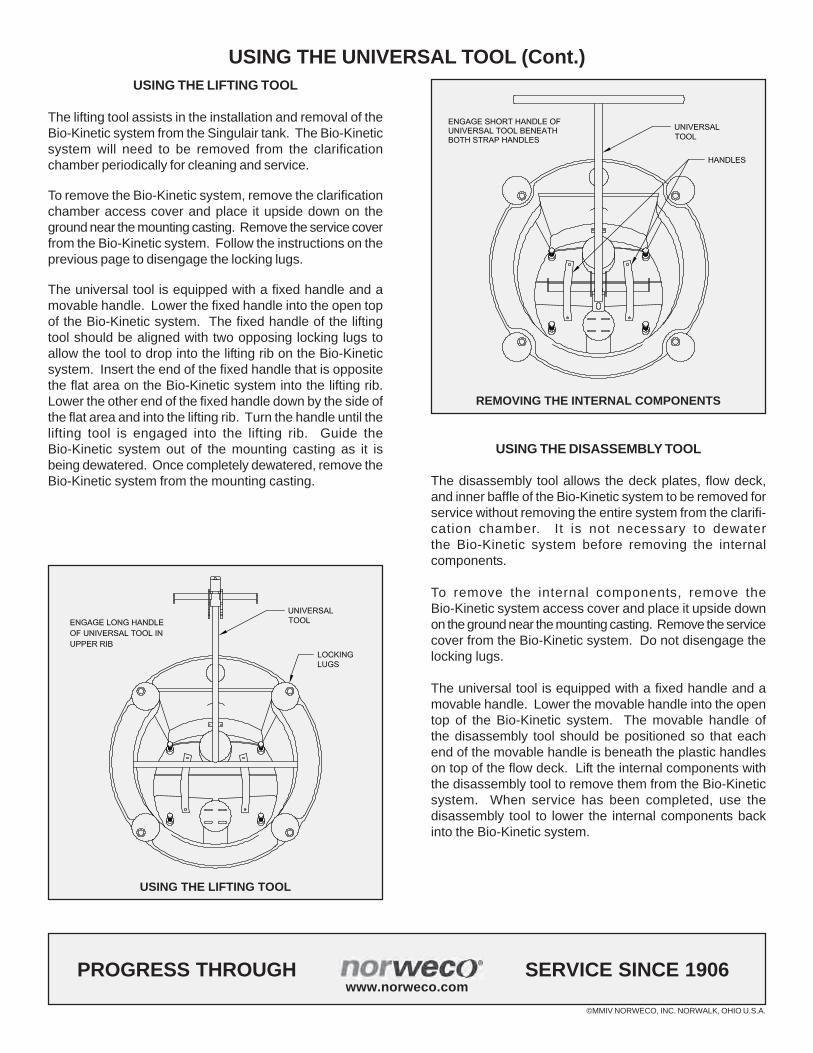
©MMIV NORWECO, INC. NORWALK, OHIO U.S.A.
PROGRESS THROUGH SERVICE SINCE 1906www.norweco.com
USING THE UNIVERSAL TOOL (Cont.)
USING THE LIFTING TOOL
REMOVING THE INTERNAL COMPONENTS
USING THE LIFTING TOOL
The lifting tool assists in the installation and removal of theBio-Kinetic system from the Singulair tank. The Bio-Kineticsystem will need to be removed from the clarificationchamber periodically for cleaning and service.
To remove the Bio-Kinetic system, remove the clarificationchamber access cover and place it upside down on theground near the mounting casting. Remove the service coverfrom the Bio-Kinetic system. Follow the instructions on theprevious page to disengage the locking lugs.
The universal tool is equipped with a fixed handle and amovable handle. Lower the fixed handle into the open topof the Bio-Kinetic system. The fixed handle of the liftingtool should be aligned with two opposing locking lugs toallow the tool to drop into the lifting rib on the Bio-Kineticsystem. Insert the end of the fixed handle that is oppositethe flat area on the Bio-Kinetic system into the lifting rib.Lower the other end of the fixed handle down by the side ofthe flat area and into the lifting rib. Turn the handle until thelifting tool is engaged into the lifting rib. Guide theBio-Kinetic system out of the mounting casting as it isbeing dewatered. Once completely dewatered, remove theBio-Kinetic system from the mounting casting.
USING THE DISASSEMBLY TOOL
The disassembly tool allows the deck plates, flow deck,and inner baffle of the Bio-Kinetic system to be removed forservice without removing the entire system from the clarifi-cation chamber. It is not necessary to dewaterthe Bio-Kinetic system before removing the internalcomponents.
To remove the internal components, remove theBio-Kinetic system access cover and place it upside downon the ground near the mounting casting. Remove the servicecover from the Bio-Kinetic system. Do not disengage thelocking lugs.
The universal tool is equipped with a fixed handle and amovable handle. Lower the movable handle into the opentop of the Bio-Kinetic system. The movable handle ofthe disassembly tool should be positioned so that eachend of the movable handle is beneath the plastic handleson top of the flow deck. Lift the internal components withthe disassembly tool to remove them from the Bio-Kineticsystem. When service has been completed, use thedisassembly tool to lower the internal components backinto the Bio-Kinetic system.
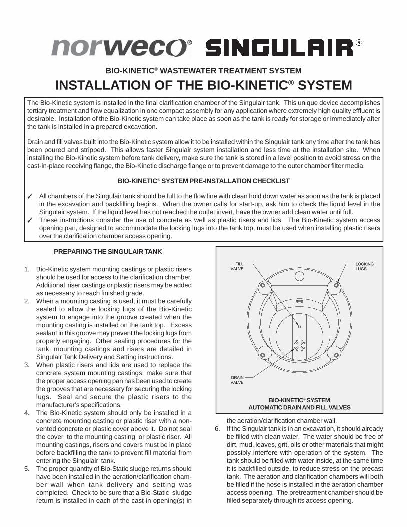
BIO-KINETIC® WASTEWATER TREATMENT SYSTEM
INSTALLATION OF THE BIO-KINETIC® SYSTEMThe Bio-Kinetic system is installed in the final clarification chamber of the Singulair tank. This unique device accomplishestertiary treatment and flow equalization in one compact assembly for any application where extremely high quality effluent isdesirable. Installation of the Bio-Kinetic system can take place as soon as the tank is ready for storage or immediately afterthe tank is installed in a prepared excavation.
Drain and fill valves built into the Bio-Kinetic system allow it to be installed within the Singulair tank any time after the tank hasbeen poured and stripped. This allows faster Singulair system installation and less time at the installation site. Wheninstalling the Bio-Kinetic system before tank delivery, make sure the tank is stored in a level position to avoid stress on thecast-in-place receiving flange, the Bio-Kinetic discharge flange or to prevent damage to the outer chamber filter media.
BIO-KINETIC® SYSTEM PRE-INSTALLATION CHECKLIST
✓ All chambers of the Singulair tank should be full to the flow line with clean hold down water as soon as the tank is placedin the excavation and backfilling begins. When the owner calls for start-up, ask him to check the liquid level in theSingulair system. If the liquid level has not reached the outlet invert, have the owner add clean water until full.
✓ These instructions consider the use of concrete as well as plastic risers and lids. The Bio-Kinetic system accessopening pan, designed to accommodate the locking lugs into the tank top, must be used when installing plastic risersover the clarification chamber access opening.
PREPARING THE SINGULAIR TANK
1. Bio-Kinetic system mounting castings or plastic risersshould be used for access to the clarification chamber.Additional riser castings or plastic risers may be addedas necessary to reach finished grade.
2. When a mounting casting is used, it must be carefullysealed to allow the locking lugs of the Bio-Kineticsystem to engage into the groove created when themounting casting is installed on the tank top. Excesssealant in this groove may prevent the locking lugs fromproperly engaging. Other sealing procedures for thetank, mounting castings and risers are detailed inSingulair Tank Delivery and Setting instructions.
3. When plastic risers and lids are used to replace theconcrete system mounting castings, make sure thatthe proper access opening pan has been used to createthe grooves that are necessary for securing the lockinglugs. Seal and secure the plastic risers to themanufacturer’s specifications.
4. The Bio-Kinetic system should only be installed in aconcrete mounting casting or plastic riser with a non-vented concrete or plastic cover above it. Do not sealthe cover to the mounting casting or plastic riser. Allmounting castings, risers and covers must be in placebefore backfilling the tank to prevent fill material fromentering the Singulair tank.
5. The proper quantity of Bio-Static sludge returns shouldhave been installed in the aeration/clarification cham-ber wall when tank delivery and setting wascompleted. Check to be sure that a Bio-Static sludgereturn is installed in each of the cast-in opening(s) in
BIO-KINETIC® SYSTEMAUTOMATIC DRAIN AND FILL VALVES
the aeration/clarification chamber wall.6. If the Singulair tank is in an excavation, it should already
be filled with clean water. The water should be free ofdirt, mud, leaves, grit, oils or other materials that mightpossibly interfere with operation of the system. Thetank should be filled with water inside, at the same timeit is backfilled outside, to reduce stress on the precasttank. The aeration and clarification chambers will bothbe filled if the hose is installed in the aeration chamberaccess opening. The pretreatment chamber should befilled separately through its access opening.
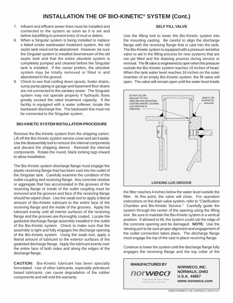
MANUFACTURED BYNORWECO, INC.NORWALK, OHIOU.S.A. 44857www.norweco.com
©MMVI NORWECO, INC. NORWALK, OHIO U.S.A.
INSTALLATION THE OF BIO-KINETIC® SYSTEM (Cont.)7. Influent and effluent sewer lines must be installed and
connected to the system as soon as it is set andbefore backfilling to prevent entry of mud or debris.
8. When a Singular system is being installed to replacea failed onsite wastewater treatment system, the oldseptic tank need not be abandoned. However, be surethe Singulair system is installed downstream of the oldseptic tank and that the entire obsolete system iscompletely pumped and cleaned before the Singulairtank is installed. If the owner prefers, the obsoletesystem may be totally removed or filled in andabandoned in the ground.
9. Check to see that roofing down spouts, footer drains,sump pump piping or garage and basement floor drainsare not connected to the sanitary sewer. The Singulairsystem may not operate properly if hydraulic flowsgreatly exceed the rated treatment capacity. If thefacility is equipped with a water softener, locate thebackwash discharge line. The backwash line must notbe connected to the Singulair system.
BIO-KINETIC SYSTEM INSTALLATION PROCEDURE
Remove the Bio-Kinetic system from the shipping carton.Lift off the Bio-Kinetic system service cover and set it aside.Use the disassembly tool to remove the internal componentsand discard the shipping sleeve. Reinstall the internalcomponents. Rotate the round, black locking lugs inwardto allow installation.
The Bio-Kinetic system discharge flange must engage theplastic receiving flange that has been cast into the outlet ofthe Singulair tank. Carefully examine the condition of theoutlet coupling and receiving flange. Any concrete residueor aggregate that has accumulated in the grooves of thereceiving flange or inside of the outlet coupling must beremoved and the grooves and face of the receiving flangeshould be wiped clean. Use the swab tool to apply a liberalamount of Bio-Kinetic lubricant to the entire face of thereceiving flange and the inside of the grooves. Apply thelubricant evenly until all interior surfaces of the receivingflange and the grooves are thoroughly coated. Locate thegasketed discharge flange assembly installed in the outletof the Bio-Kinetic system. Check to make sure that theassembly is tight and fully engages the discharge openingof the Bio-Kinetic system. Using the swab tool, apply aliberal amount of lubricant to the exterior surfaces of thegasketed discharge flange. Apply the lubricant evenly overthe entire face of both sides and along the edges of thedischarge flange.
CAUTION: Bio-Kinetic lubricant has been speciallyformulated. Use of other lubricants, especially petroleumbased lubricants, can cause degradation of the rubbercomponents and will void the warranty.
SELF FILL VALVE
Use the lifting tool to lower the Bio-Kinetic system intothe mounting casting. Be careful to align the dischargeflange with the receiving flange that is cast into the tank.The Bio-Kinetic system is equipped with a pressure sensitivevalve to aid in the filling process for new systems that arenot yet filled and the draining process during service orremoval. The fill valve is engineered to open when the pressureoutside the Bio-Kinetic system reaches 16 inches of head.When the tank water level reaches 16 inches on the outerchamber of an empty Bio-Kinetic system, the fill valve willopen. The valve will remain open until the water level inside
the filter reaches 4 inches below the water level outside thefilter. At this point, the valve will close. For operationinstructions on the drain valve system, refer to “ClarificationChamber and Bio-Kinetic Service.” Carefully guide thesystem through the center of the opening using the liftingtool. Be sure to maintain the Bio-Kinetic system in a verticalposition. If allowed to tilt, the system could rub the edge ofthe concrete opening and be damaged. NOTE: Use theviewing port to be sure proper alignment and engagement ofthe outlet connection takes place. The discharge flangemust engage the top of the cast in place receiving flange.
Continue to lower the system until the discharge flange fullyengages the receiving flange and the top collar of the
LOCKING LUG GROOVE
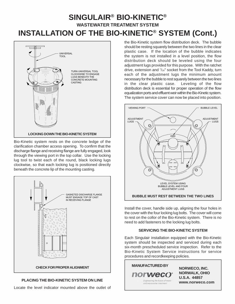
INSTALLATION OF THE BIO-KINETIC® SYSTEM (Cont.)
SINGULAIR® BIO-KINETIC®
WASTEWATER TREATMENT SYSTEM
Bio-Kinetic system rests on the concrete ledge of theclarification chamber access opening. To confirm that thedischarge flange and receiving flange are fully engaged, lookthrough the viewing port in the top collar. Use the lockinglug tool to twist each of the round, black locking lugsclockwise, so that each locking lug is positioned directlybeneath the concrete lip of the mounting casting.
the Bio-Kinetic system flow distribution deck. The bubbleshould be resting squarely between the two lines in the clearplastic case. If the location of the bubble indicatesthe system is not installed in a level position, the flowdistribution deck should be leveled using the fouradjustment lugs provided for this purpose. With the ratchetdrive, extension and 7/16" socket from the Tool Kaddy, turneach of the adjustment lugs the minimum amountnecessary for the bubble to rest squarely between the two linesin the clear plastic case. Leveling of the flowdistribution deck is essential for proper operation of the flowequalization ports and effluent weir within the Bio-Kinetic system.The system service cover can now be placed into position.
Install the cover, handle side up, aligning the four holes inthe cover with the four locking lug bolts. The cover will cometo rest on the collor of the Bio-Kinetic system. There is noneed to add fasteners to the locking lug bolts.
SERVICING THE BIO-KINETIC SYSTEM
Each Singulair installation equipped with the Bio-Kineticsystem should be inspected and serviced during eachsix-month prescheduled service inspection. Refer to theBio-Kinetic System Service instructions for serviceprocedures and recordkeeping policies.
LOCKING DOWN THE BIO-KINETIC SYSTEM
MANUFACTURED BYNORWECO, INC.NORWALK, OHIOU.S.A. 44857www.norweco.com
CHECK FOR PROPER ALIGNMENT
BUBBLE MUST REST BETWEEN THE TWO LINES
PLACING THE BIO-KINETIC SYSTEM ON LINE
Locate the level indicator mounted above the outlet of
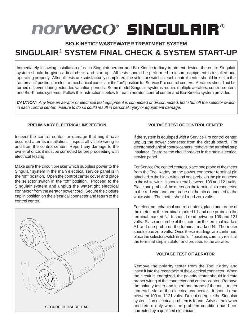
BIO-KINETIC® WASTEWATER TREATMENT SYSTEM
SINGULAIR® SYSTEM FINAL CHECK & SYSTEM START-UP
PRELIMINARY ELECTRICAL INSPECTION
Inspect the control center for damage that might haveoccurred after its installation. Inspect all visible wiring toand from the control center. Report any damage to theowner at once; it must be corrected before proceeding withelectrical testing.
Make sure the circuit breaker which supplies power to theSingulair system in the main electrical service panel is inthe “off” position. Open the control center cover and placethe selector switch in the “off” position. Proceed to theSingulair system and unplug the watertight electricalconnector from the aerator power cord. Secure the closurecap in position on the electrical connector and return to thecontrol center.
VOLTAGE TEST OF CONTROL CENTER
If the system is equipped with a Service Pro control center,unplug the power connector from the circuit board. Forelectromechanical control centers, remove the terminal stripinsulator. Energize the circuit breaker in the main electricalservice panel.
For Service Pro control centers, place one probe of the meterfrom the Tool Kaddy on the power connector terminal pinattached to the black wire and one probe on the pin attachedto the white wire. It should read between 109 and 121 volts.Place one probe of the meter on the terminal pin connectedto the red wire and one probe on the pin connected to thewhite wire. The meter should read zero volts.
For electromechanical control centers, place one probe ofthe meter on the terminal marked L1 and one probe on theterminal marked N. It should read between 109 and 121volts. Place one probe of the meter on the terminal markedA1 and one probe on the terminal marked N. The metershould read zero volts. Once these readings are confirmed,place the selector switch in the “off” position, carefully reinstallthe terminal strip insulator and proceed to the aerator.
VOLTAGE TEST OF AERATOR
Remove the polarity tester from the Tool Kaddy andinsert it into the receptacle of the electrical connector. Whenthe circuit is energized, the polarity tester should indicateproper wiring of the connector and control center. Removethe polarity tester and insert one probe of the multi-meterinto each slot of the electrical connector. It should readbetween 109 and 121 volts. Do not energize the Singulairsystem if an electrical problem is found. Advise the ownerand return only when the problem condition has beencorrected by a qualified electrician.
SECURE CLOSURE CAP
Immediately following installation of each Singulair aerator and Bio-Kinetic tertiary treatment device, the entire Singulairsystem should be given a final check and start-up. All tests should be performed to insure equipment is installed andoperating properly. After all tests are satisfactorily completed, the selector switch in each control center should be set to the“automatic” position for electro-mechanical panels, or the “on” position for Service Pro control centers. Aerators should not beturned off, even during extended vacation periods. Some model Singulair systems require multiple aerators, control centersand Bio-Kinetic systems. Follow the instructions below for each aerator, control center and Bio-Kinetic system provided.
CAUTION: Any time an aerator or electrical test equipment is connected or disconnected, first shut off the selector switchin each control center. Failure to do so could result in personal injury or equipment damage.
MANUFACTURED BYNORWECO, INC.NORWALK, OHIOU.S.A. 44857www.norweco.com
©MMVI NORWECO, INC. NORWALK, OHIO U.S.A.
SINGULAIR® SYSTEM FINAL CHECK & SYSTEM START-UP (Cont.)AMPERAGE TEST
Remove the electrical test pigtail from the Tool Kaddy andplace the current sensor of the multi-meter around theexposed black lead of the test pigtail. Plug the test pigtailin line between the two halves of the watertight electricalconnector. When energized, read the current draw of theaerator. The initial reading should never be greater than4.2 amps. After 48 hours of operation, break-in of themechanical seals will allow the amp draw to drop to 3.8amps or less. If an excessive current reading is obtained,de-energize the aerator immediately and do notre-energize it until the cause is found and corrected. Whenthe test is complete, place the control center selector switchin the “off” position, unplug the test pigtail at both ends andplug the aerator directly into the receptacle on theunderground electrical service cable. Make sure the twohalves of the connector are firmly engaged to insure theintegrity of the multiple lip seal for a moisture proofconnection. Place the control center in “continuous” runoperation.
AERATOR INSPECTION
Check the aerator to make sure it is running smoothlywithout vibration. Make sure the four brackets areproperly seated in the four cast-in grooves. Arrange thepower cord assembly and electrical connector so they aresecured in the mounting clips and are not touching the topof the aerator. Confirm that the debris screens are in placein the air intake ports. Replace the vented cover over theaerator mounting casting and check for excessive noise.Listen for evidence of debris in the aeration chamber strikingthe aspirator shaft. Occasionally, discarded constructionmaterials may enter the sewer line and Singulair tank.They must be removed at once so that the aspirator shaftstraightness tolerance is not compromised. Inspect thevent cap openings to assure the unrestricted passage of air.
FINAL INSPECTION OF BIO-KINETIC SYSTEM
Remove the concrete cover from the clarificationchamber access opening. Remove the Bio-Kinetic systemservice cover. Inspect the black locking lugs to make surethey are fully engaged beneath the concrete mountingcasting. Inspect the level indicator to be sure that the Bio-Kinetic system is installed in a level position to insure properoperation. Replace the system service cover. Replace theconcrete access cover.
INSPECTION OF EFFLUENT DISPOSAL SYSTEM
Inspect the final discharge point to make sure that theoutlet is unrestricted. If you suspect any possibility of adrainage problem, report it to the owner and request thatcorrective action be taken immediately. The system couldbe subjected to high water and liquid may back up into theinlet sewer line if not corrected. Locate the ground water
relief point and insure it is clean and unobstructed.
When an effluent lift pump or other accessory equipmenthas been installed as part of the Singulair system, theseitems must be started-up, and placed into operation at thistime. Refer to the individual start-up instructions furnishedwith accessory equipment and test them accordingly.
WHEN YOUR INSPECTIONS ARE COMPLETE
Place the selector switch in the Singulair control center inthe “automatic” or “on” position, depending upon the model.Latch the control center cover and secure it with a tamperevident seal. Notify the owner that the Singulair system isoperating properly. Ask if there are any questions regardingsystem operation. Most start-up problems are caused byimproper or incomplete installation of the system or becauseof a misunderstanding on the part of the contractor or owner.Refer to the Singulair Trouble-Shooting guide for direction ifa problem is discovered during start-up.
INTEGRATED SYSTEM CONTROLS
SINGULAIR® SYSTEM FINAL CHECK & SYSTEM START-UPWhen Singulair wastewater treatment systems are installed in conjunction with effluent disposal systems requiring pumping,the optional integrated system controls allow both aerator and pump operations to be controlled from a single panel. Basedon the specific Singulair model number and the corresponding quantity of aerators and effluent pumps required, integratedsystem controls are available in simplex aerator/simplex pump, duplex aerators/simplex pump and duplex aerators/duplexpumps configurations. Optional features allow chemical level monitoring, failsafe pump control and telemetry.
These instructions are directed only to the specific requirements of the optional integrated system controls. They are notintended to cover all aspects of preliminary inspection of the Singulair system. Additional instructions are contained inBio-Kinetic wastewater treatment system Singulair System Final Check and System Start-up.
PRELIMINARY ELECTRICAL INSPECTION
CAUTION: Before initiating any electrical componentinspection, turn off all power to the Singulair systemand test for voltage with the electrical multi-meter fromthe Service Pro Tool Kaddy. Inspection and repairsshould always be made by a qualified electrician usingproper procedures and safe tools. Make sure all circuitsare properly grounded. Do not stand in damp locationswhen making electrical system tests. Always use toolswith insulated handles for electrical repairs. Inspectthe Singulair integrated system controls for damagethat may have occurred after its installation. Inspectall visible wiring to and from the control center. Report anydamage to the owner at once. Any damage must be correctedbefore proceeding with electrical testing.
Make sure that the circuit breaker which supplies power tothe Singulair system from the main electrical service panelis in the “off” position. Open the control center cover andmake sure all circuit breakers and selector switches are inthe “off” or “normal” position. Proceed to the Singulair systemand unplug each watertight electrical connector. Securethe closure cap in position on each electrical connector andreturn to the control center.
VOLTAGE TEST OF CONTROL CENTER
Energize the circuit breaker in the main electrical servicepanel, as well as all circuit breakers in the integrated systemcontrols. If the control center is equipped with the optionalfailsafe pump control feature, the alarms may activate. Ifthis occurs, place the ALARM SILENCE switch in the“silence” position. Remove the electrical multi-meter fromthe Tool Kaddy to test the voltage being supplied. Set upthe meter to read AC voltage on the 0-150 volt scale. Placeone probe of the meter on the terminal marked L1 and oneprobe on the adjacent terminal marked N. It should readbetween 109-121 volts. If it is within these limits, place one
probe of the multi-meter on one of the terminals marked A1and one probe on the adjacent terminal marked N. Themeter should read 0 volts. Repeat this step for all otherterminals marked AERATOR POWER. If zero voltage isindicated at all terminals marked A1 or A2, move the controlcenter selector switch to the “continuous” position and theALARM SILENCE switch to the “normal” position. The metershould now read the same as the incoming voltage betweeneach set of terminals marked AERATOR POWER. Checkthe voltage at all sets of terminals marked A1 or A2 and N. Ifthe voltage reads the same as incoming voltage, move thecontrol center selector switch to the “automatic” position.Rotate the aerator timer knob until voltage is read. Themeter should now read the same as the incoming voltagebetween each set of terminals marked AERATOR POWER.Manually rotate the aerator timer knob approximately 1/2 turnuntil the meter reads 0 volts. Once these readings areconfirmed for all sets of terminals marked AERATORPOWER, place the aerator selector switch in the “off” position.
ALARM TESTING
Test the alarm functions by placing the SYSTEM TESTswitch in the “alarm test” position. The audible alarm shouldsound and the warning lights should illuminate. Place theALARM SILENCE switch in the “silence” position. Theaudible alarm should not sound, but the all warning lightsshould continue to illuminate. Return both the SYSTEMTEST and ALARM SILENCE switches to the “normal”position.
Place the control center selector switch in the “continuous”position. Test the yellow aerator alarm light by de-energizingthe aerator circuit breaker. The yellow aerator alarm lightshould illuminate and the audible alarm will sound.Re-energize the aerator circuit breaker.
Check the pump tank to see that all floats are hanging down,which is the “off” position. Place one probe of the
MANUFACTURED BY
©MMIV NORWECO, INC. NORWALK, OHIO U.S.A.
NORWECO, INC.NORWALK, OHIOU.S.A. 44857
SINGULAIR® SYSTEM FINAL CHECK & SYSTEM START-UP (Cont.)multi-meter on a terminal marked P1 and the other probe onthe adjacent terminal marked N. The meter should read 0volts. Repeat this step for all other terminals marked PUMPPOWER. If zero voltage is indicated at all terminals markedPUMP POWER, be sure the trippers on the pump timer inthe enabled (outboard) position are in alignment with thetriangular indicator on the inner face of the timer unit. At thepump tank, raise the lowest float (in the case of a 3 floatpump station, or the lowest two floats in the case of a 4 floatpump station), and secure them in the vertically “up” position.Return to the control center and again check the voltage atthe terminals marked PUMP POWER. One set of terminalsin the simplex pump panel and one of the two sets ofterminals in the duplex panel should now read the same asthe incoming voltage. Rotate the pump timer dial clockwiseuntil the trippers in the disabled (inboard) position are inalignment with the triangular indicator on the inner face ofthe timer unit. All sets of PUMP POWER terminals shouldnow read zero volts. In the case of a duplex pump panel,rotate the pump timer dial clockwise until the trippers in theenabled (outboard) position are in alignment with thetriangular indicator on the inner face of the timer unit. Again,check the voltage at the terminals marked PUMP POWER.The alternate set of terminals should now read the same asthe incoming voltage.
Return to the pump tank, invert the alarm float and secure itin the vertically “up” position. The audible and red visualalarms should be activated. Invert the highest float to avertically “up” position and secure it. Check the voltage atall sets of terminals marked PUMP POWER. The metershould now read the same as the incoming voltage at eachset of terminals. Return all floats to their vertically “down”position. If the integrated control center is equipped withduplex pump controls, press reset. The audible alarm shouldstop sounding and the red warning light should go off.
Check to make sure the trippers on the pump timer areenabled only during the time required by local regulations.Turn the outer ring dial of the pump timer until the correcttime of day is currently displayed opposite the triangularindicator on the inner ring of the timer. Place the aeratorselector switch in the “off” position.
OPTIONAL TELEMETRY SYSTEM
Systems equipped with the optional telemetry feature mustbe programmed prior to being placed into operation. Beginprogramming the auto-dialer by placing the power switch onthe dialer in the “on” position. Press the MODE button toselect the PROGRAM mode. “Program” should appear onthe dialer display. Press all of the digits of the first numberto be dialed. The display can be used to check accuracy,as it will display every number pressed. Momentarily pressthe MEMORY button after the entire phone number has beenentered. Next, press the 1 key. This number is now storedin memory location 1. To program a phone number intomemory location 2, enter all of the digits for the second
member to be dialed, momentarily press the MEMORYbutton, then press the 2 key. Repeat this process formemory locations 3 and 4, if desired.
Record an outgoing voice message that identifies the locationof the Singulair system by locating the microphone in thelower right corner of the speaker. When recording amessage, talk of a normal voice about 10 inches from themicrophone. Place the unit in the PROGRAM mode bypressing the MODE button. Next, press the 1 button. Torecord, press and hold the VOICE button down to initiatethe 16 second recording process. The word “Voice” willappear on the display during recording. The VOICE buttonmust be pressed for the entire time of recording. When theVOICE button is released, the word “Voice” will disappearfrom the display indicating that the recording process iscomplete.
To test the telemetry system, first notify all individuals thatthe system is programmed to call. Next, place the SYSTEMTEST switch in the “alarm test” position. The audible andvisual alarms should activate. The audible portion of thealarm may be disabled by placing the ALARM SILENCEswitch in the “silence” position. The dialer system is equippedwith a built in three minute delay. After three minutes, thedisplay should read “Alarm On.” Allow the system severalminutes to dial out. Place the SYSTEM TEST switch backinto the “normal” position. Press the MODE button on thedialer until the display reads “Operate.” Call each numberthe dialer was programmed to call and verify that the recordedvoice message was received.
INTEGRATED SYSTEM CONTROLS
FINAL INSTRUCTIONS TO THE OWNER
CONTROL CENTER SERVICE
CAUTION: If your visual inspection of the Singulaircontrol center reveals a problem, be sure to shut offthe appropriate circuit breaker in the main servicepanel, then test all circuits with the electricalmulti-meter to be sure they are de-energized prior toproceeding.
Control center service should be performed during eachservice inspection and should follow all parameters outlinedin the Singulair Service Manual.
NOTE: The performance of the Singulair Model TNT systemhas been tested and certified with the aerator(s) operatingon a 60 minute on / 60 minute off time cycle.
1. If there is no evidence of an electrical problem, checkthe main service panel to see that the circuit breaker isin the “on” position.
2. Check to see that all circuit breakers within the integratedcontrol center are in the “on” position.
3. Check the aerator selector switch in the Singulairintegrated control center to make sure that it is set to“automatic” operation.
4. Check all alarm selector switches in the Singulair controlcenter to see that all alarm functions are in the “normal”position.
5. Verify that your company’s identification label is affixedto the Singulair control center and is legible. Replacethe label if necessary.
6. Inspect wiring from the control center to the aerator(s)and pump(s) as far as it is visible, and notify the ownerif you see any damaged areas.
7. As you leave, make sure that the Singulair control centeris set for “automatic” operation for all aerators andpumps.
ELECTRICAL TROUBLESHOOTING
CAUTION: Before initiating any electrical component
When Singulair wastewater treatment systems are installed in conjunction with effluent disposal systems requiring pumping,the optional integrated system controls allow both aerator and pump operations to be controlled from a single panel. Basedon the specific Singulair model number, the corresponding quantity of aerators, and quantity of effluent pumps required,integrated system controls are available in simplex aerator/simplex pump, duplex aerators/simplex pump and duplexaerators/duplex pumps configurations.
These instructions are directed only to the specific requirements of the optional integrated system controls. They are notintended to cover all aspects of service of the control center or troubleshooting. Additional instructions are contained inBio-Kinetic wastewater treatment system Final Instructions to the Owner and Aerator Troubleshooting.
inspection or repair, turn off all power to the Singulairsystem by switching off the dedicated circuit breakerin the main electrical service panel and then test withthe electrical multi-meter. Repairs should always bemade by a qualified electrician using properprocedures and safe tools. Make sure that all circuitsare properly grounded. Do not stand in damp locationswhen making electrical system tests. Always use toolswith insulated handles for electrical repairs.
No electrical power from Follow instructions detailedelectrical service panel in “Electrical Troubleshootingto control center Section” of the Singulair
Service ManualNo electrical power from Follow instructions detailedcontrol center to aerator in “Electrical Troubleshooting
Section” of the SingulairService Manual
No electrical power from Check to see that pumpcontrol center to pump circuit breaker is in the “on”
position.Check to see that “on” float inpump station wet well iselevated to its “closed”position.Check all wiring from controlcenter to pump.
Aerator will not start Follow instructions detailedin “Electrical TroubleshootingSection” of the SingulairService Manual
Pump will not start See instructions containedin Pump Operation andMaintenance ManualReplace defective float
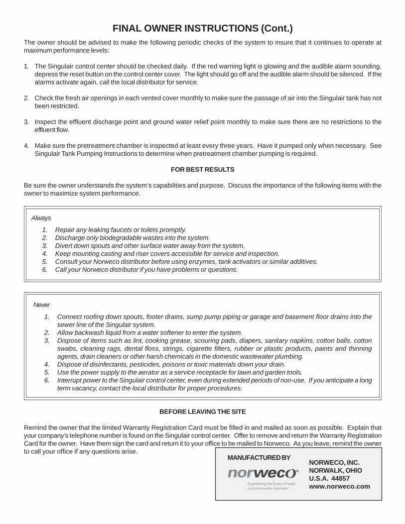
MANUFACTURED BYNORWECO, INC.NORWALK, OHIOU.S.A. 44857www.norweco.com
FINAL OWNER INSTRUCTIONS (Cont.)The owner should be advised to make the following periodic checks of the system to insure that it continues to operate atmaximum performance levels:
1. The Singulair control center should be checked daily. If the red warning light is glowing and the audible alarm sounding,depress the reset button on the control center cover. The light should go off and the audible alarm should be silenced. If thealarms activate again, call the local distributor for service.
2. Check the fresh air openings in each vented cover monthly to make sure the passage of air into the Singulair tank has notbeen restricted.
3. Inspect the effluent discharge point and ground water relief point monthly to make sure there are no restrictions to theeffluent flow.
4. Make sure the pretreatment chamber is inspected at least every three years. Have it pumped only when necessary. SeeSingulair Tank Pumping Instructions to determine when pretreatment chamber pumping is required.
FOR BEST RESULTS
Be sure the owner understands the system’s capabilities and purpose. Discuss the importance of the following items with theowner to maximize system performance.
Always
1. Repair any leaking faucets or toilets promptly.2. Discharge only biodegradable wastes into the system.3. Divert down spouts and other surface water away from the system.4. Keep mounting casting and riser covers accessible for service and inspection.5. Consult your Norweco distributor before using enzymes, tank activators or similar additives.6. Call your Norweco distributor if you have problems or questions.
Never
1. Connect roofing down spouts, footer drains, sump pump piping or garage and basement floor drains into thesewer line of the Singulair system.
2. Allow backwash liquid from a water softener to enter the system.3. Dispose of items such as lint, cooking grease, scouring pads, diapers, sanitary napkins, cotton balls, cotton
swabs, cleaning rags, dental floss, strings, cigarette filters, rubber or plastic products, paints and thinningagents, drain cleaners or other harsh chemicals in the domestic wastewater plumbing.
4. Dispose of disinfectants, pesticides, poisons or toxic materials down your drain.5. Use the power supply to the aerator as a service receptacle for lawn and garden tools.6. Interrupt power to the Singulair control center, even during extended periods of non-use. If you anticipate a long
term vacancy, contact the local distributor for proper procedures.
BEFORE LEAVING THE SITE
Remind the owner that the limited Warranty Registration Card must be filled in and mailed as soon as possible. Explain thatyour company’s telephone number is found on the Singulair control center. Offer to remove and return the Warranty RegistrationCard for the owner. Have them sign the card and return it to your office to be mailed to Norweco. As you leave, remind the ownerto call your office if any questions arise.
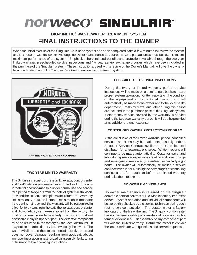
BIO-KINETIC® WASTEWATER TREATMENT SYSTEM
FINAL INSTRUCTIONS TO THE OWNERWhen the initial start-up of the Singulair Bio-Kinetic system has been completed, take a few minutes to review the systemand its operation with the owner. Although no owner maintenance is required, several precautions should be taken to insuremaximum performance of the system. Emphasize the continued benefits and protection available through the two yearlimited warranty, prescheduled service inspections and fifty year aerator exchange program which have been included inthe purchase of the Singulair system. These instructions, used with a review of the Owner’s Manual, will give the owner abasic understanding of the Singulair Bio-Kinetic wastewater treatment system.
TWO YEAR LIMITED WARRANTY
The Singulair precast concrete tank, aerator, control centerand Bio-Kinetic system are warranted to be free from defectsin material and workmanship under normal use and servicefor a period of two years from the date of system installation,provided the customer completes and returns the WarrantyRegistration Card to the factory. Registration is important:if the card is not received, the warranty will be recognized ineffect for two years from the date the aerator, control centerand Bio-Kinetic system were shipped from the factory. Toqualify for service under warranty, the owner must notdisassemble any component part. The defective componentmust be returned to the factory by the local distributor. Itmay not be returned directly to Norweco by the owner. Thewarranty is limited to the replacement of defective parts anddoes not cover damage resulting from accident, abuse,improper installation, unauthorized disassembly, faulty wiringor failure to follow operating instructions.
PRESCHEDULED SERVICE INSPECTIONS
During the two year limited warranty period, serviceinspections will be made on a semi-annual basis to insureproper system operation. Written reports on the conditionof the equipment and quality of the effluent willautomatically be made to the owner and to the local healthdepartment. Costs for travel and labor during this periodare included in the purchase price of the Singulair system.If emergency service covered by the warranty is neededduring the two year warranty period, it will also be providedat no additional owner expense.
CONTINUOUS OWNER PROTECTION PROGRAM
At the conclusion of the limited warranty period, continuedservice inspections may be made semi-annually under aSingulair Service Contract available from the licenseddistributor for a reasonable charge. Written reports willcontinue to be made automatically. Costs for travel andlabor during service inspections are at no additional chargeand emergency service is guaranteed within forty-eighthours. The owner will automatically be mailed a servicecontract with a letter outlining the advantages of continuingservice and a fee quotation before the limited warrantyperiod is about to expire.
NO OWNER MAINTENANCE
No owner maintenance is required on the Singulairaerator, electrical controls or Bio-Kinetic tertiary treatmentdevice. System operation and individual components willbe thoroughly checked by the service technician during eachroutine service inspection. The aerator motor is factorylubricated for the life of the unit. The Singulair control centerhas no user-serviceable parts inside and is secured with atamper evident seal. Disassembly of any component partwill void the limited warranty. Instruct the owner to contactthe local distributor with questions and service requests.
OWNER PROTECTION PROGRAM
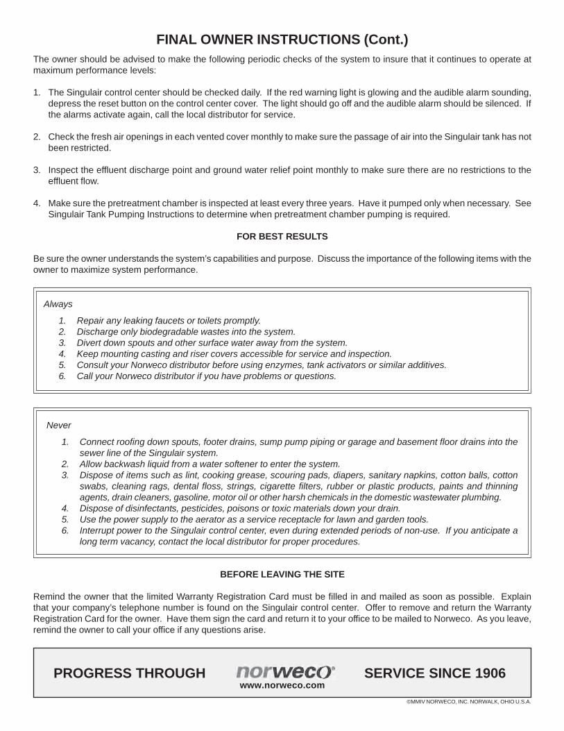
©MMIV NORWECO, INC. NORWALK, OHIO U.S.A.
PROGRESS THROUGH SERVICE SINCE 1906www.norweco.com
FINAL OWNER INSTRUCTIONS (Cont.)The owner should be advised to make the following periodic checks of the system to insure that it continues to operate atmaximum performance levels:
1. The Singulair control center should be checked daily. If the red warning light is glowing and the audible alarm sounding,depress the reset button on the control center cover. The light should go off and the audible alarm should be silenced. Ifthe alarms activate again, call the local distributor for service.
2. Check the fresh air openings in each vented cover monthly to make sure the passage of air into the Singulair tank has notbeen restricted.
3. Inspect the effluent discharge point and ground water relief point monthly to make sure there are no restrictions to theeffluent flow.
4. Make sure the pretreatment chamber is inspected at least every three years. Have it pumped only when necessary. SeeSingulair Tank Pumping Instructions to determine when pretreatment chamber pumping is required.
FOR BEST RESULTS
Be sure the owner understands the system’s capabilities and purpose. Discuss the importance of the following items with theowner to maximize system performance.
Always
1. Repair any leaking faucets or toilets promptly.2. Discharge only biodegradable wastes into the system.3. Divert down spouts and other surface water away from the system.4. Keep mounting casting and riser covers accessible for service and inspection.5. Consult your Norweco distributor before using enzymes, tank activators or similar additives.6. Call your Norweco distributor if you have problems or questions.
Never
1. Connect roofing down spouts, footer drains, sump pump piping or garage and basement floor drains into thesewer line of the Singulair system.
2. Allow backwash liquid from a water softener to enter the system.3. Dispose of items such as lint, cooking grease, scouring pads, diapers, sanitary napkins, cotton balls, cotton
swabs, cleaning rags, dental floss, strings, cigarette filters, rubber or plastic products, paints and thinningagents, drain cleaners, gasoline, motor oil or other harsh chemicals in the domestic wastewater plumbing.
4. Dispose of disinfectants, pesticides, poisons or toxic materials down your drain.5. Use the power supply to the aerator as a service receptacle for lawn and garden tools.6. Interrupt power to the Singulair control center, even during extended periods of non-use. If you anticipate a
long term vacancy, contact the local distributor for proper procedures.
BEFORE LEAVING THE SITE
Remind the owner that the limited Warranty Registration Card must be filled in and mailed as soon as possible. Explainthat your company’s telephone number is found on the Singulair control center. Offer to remove and return the WarrantyRegistration Card for the owner. Have them sign the card and return it to your office to be mailed to Norweco. As you leave,remind the owner to call your office if any questions arise.
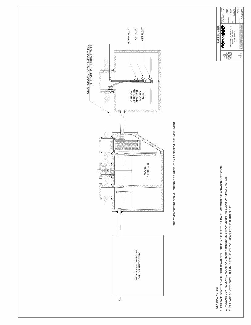
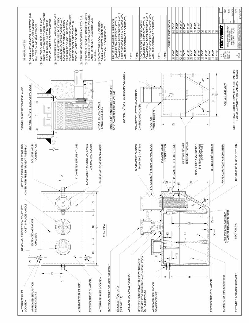
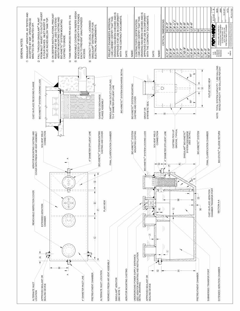
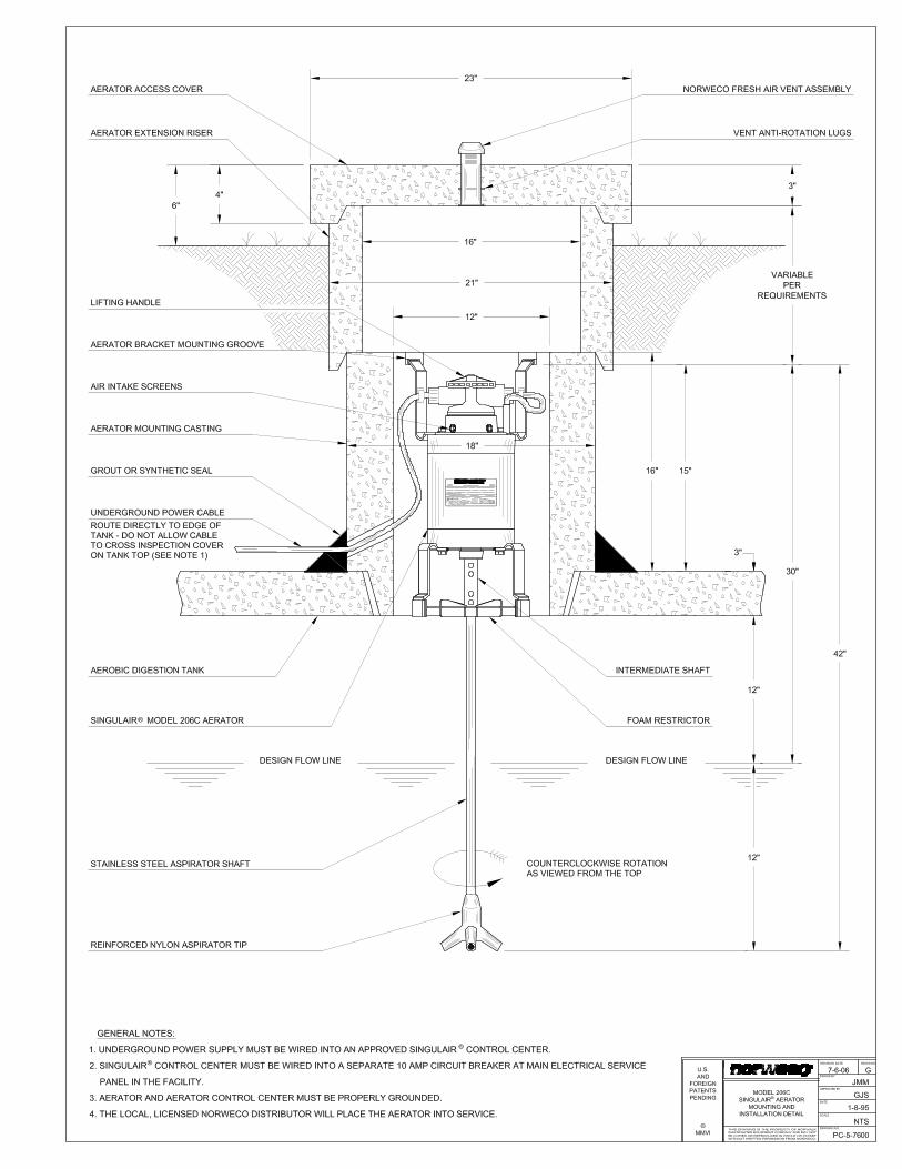
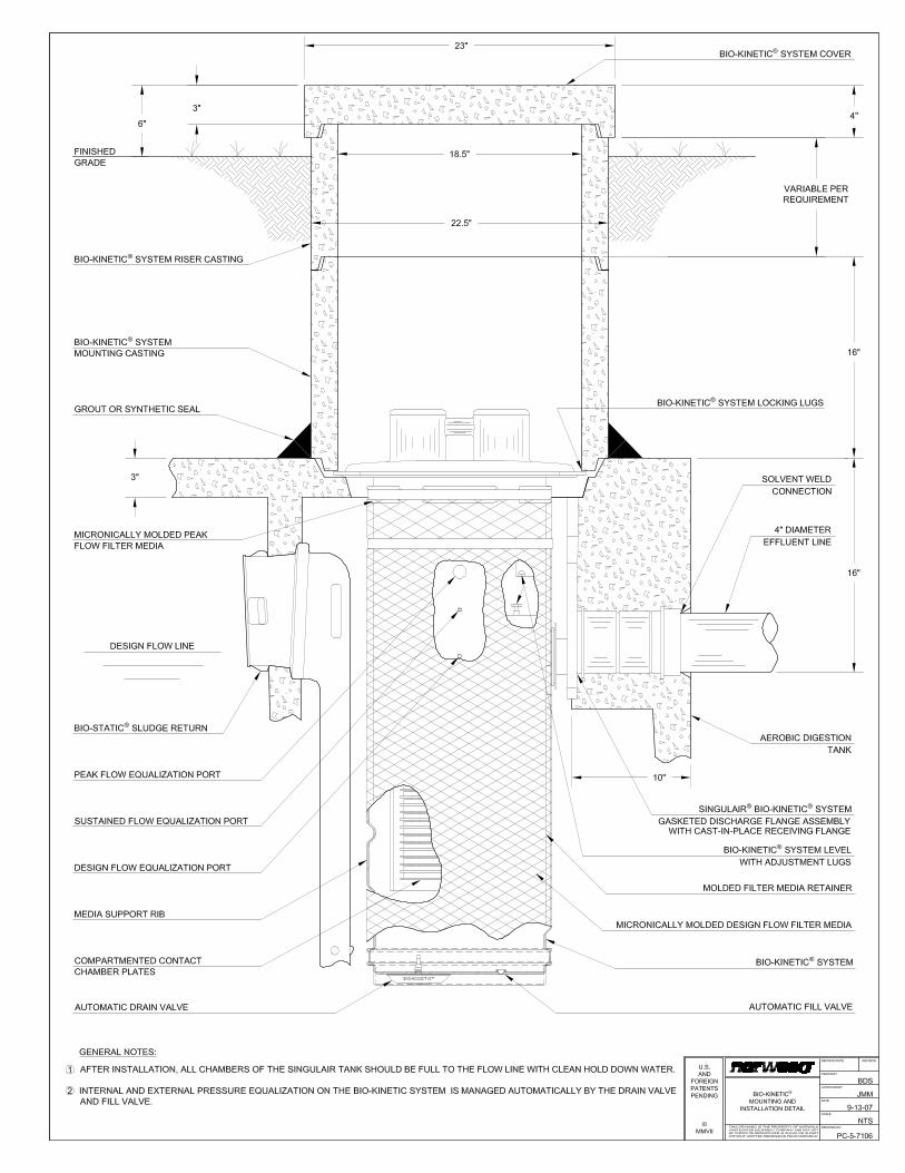
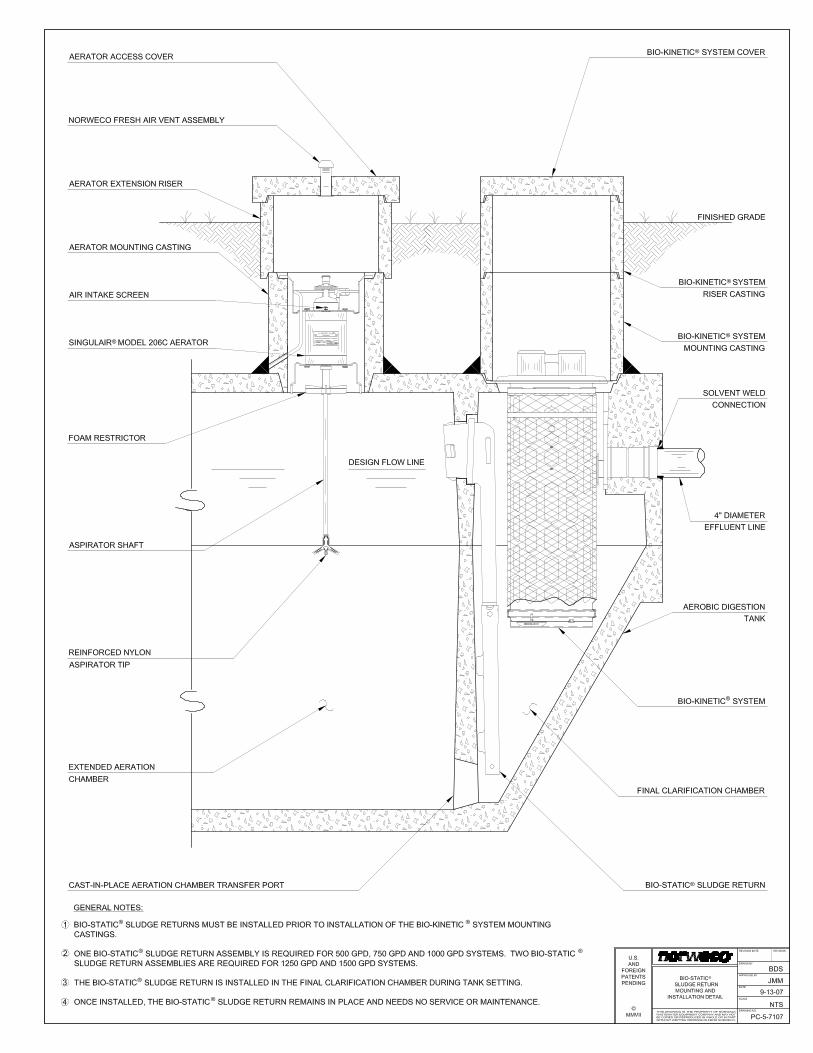
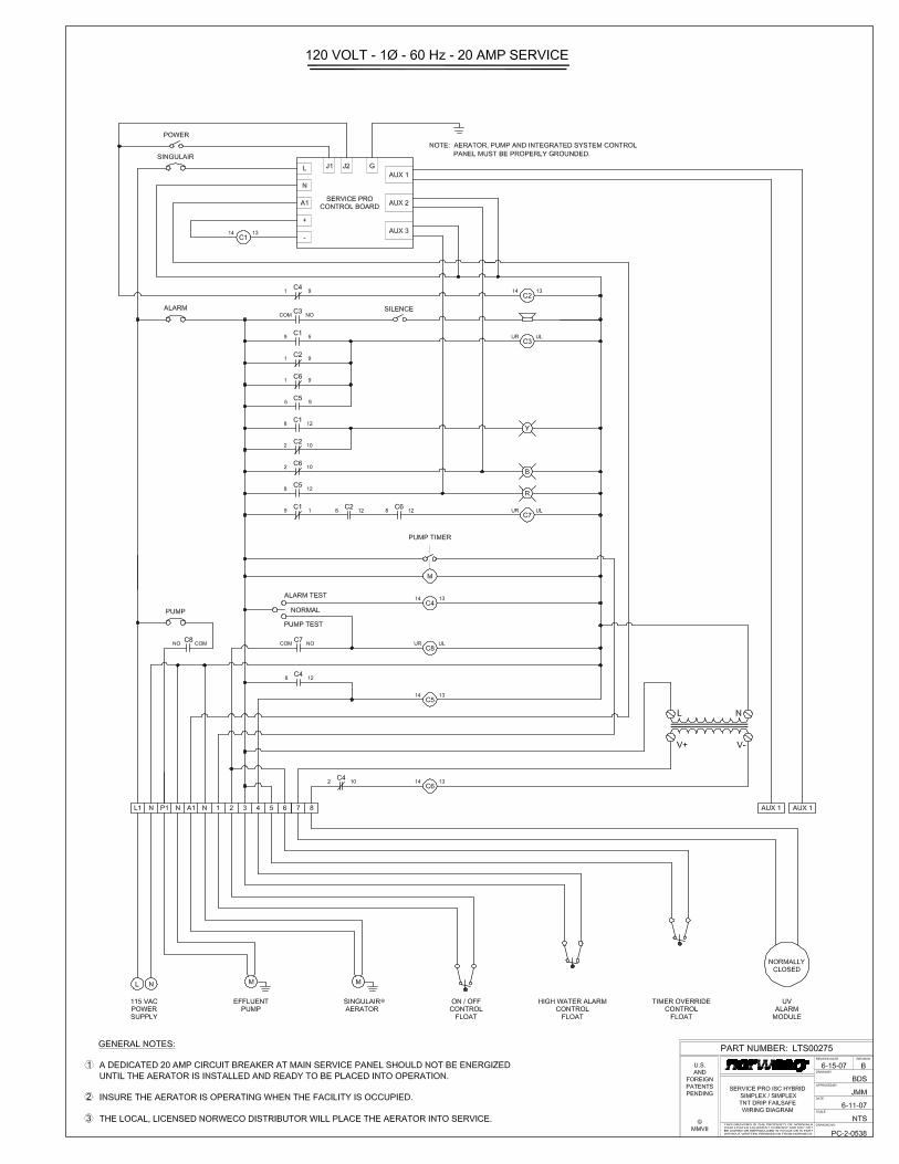
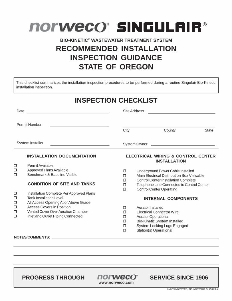
BIO-KINETIC® WASTEWATER TREATMENT SYSTEM
RECOMMENDED INSTALLATIONINSPECTION GUIDANCE
STATE OF OREGON
INSPECTION CHECKLISTDate
Permit Number
System Installer
Site Address
City County State
System Owner
INSTALLATION DOCUMENTATION
Permit AvailableApproved Plans AvailableBenchmark & Baseline Visible
CONDITION OF SITE AND TANKS
Installation Complete Per Approved PlansTank Installation LevelAll Access Opening At or Above GradeAccess Covers in PositionVented Cover Over Aeration ChamberInlet and Outlet Piping Connected
ELECTRICAL WIRING & CONTROL CENTERINSTALLATION
Underground Power Cable InstalledMain Electrical Distribution Box ViewableControl Center Installation CompleteTelephone Line Connected to Control CenterControl Center Operating
INTERNAL COMPONENTS
Aerator InstalledElectrical Connector WireAerator OperationalBio-Kinetic System InstalledSystem Locking Lugs EngagedStation(s) Operational
©MMVII NORWECO, INC. NORWALK, OHIO U.S.A.
PROGRESS THROUGH SERVICE SINCE 1906www.norweco.com
This checklist summarizes the installation inspection procedures to be performed during a routine Singulair Bio-Kineticinstallation inspection.
NOTES/COMMENTS: