Embed Size (px)
Citation preview

InstallatIon manual of stanDaRD solaR moDules
for professional use only

EN-Rev IM/GN-AM-EN/1.3 Copyright © Apr. 20th, 2018. Canadian Solar Inc.
2 |
1.0 GeneRal InfoRmatIon
1.1 InstallatIon manual DIsClaImeR
1.2 lImItatIon of lIaBIlItY
2.0 safetY PReCautIons
3.0 meCHanICal / eleCtRICal sPeCIfICatIons
4.0 unPaCKInG anD stoRaGe
5.0 moDule InstallatIon
5.1 moDule WIRInG
5.2 GRounDInG
6.0 mountInG InstRuCtIons
6.1 mountInG metHoD: BoltInG
7.0 maIntenanCe
amenDeD eDItIons anD Dates
1.0 GeneRal InfoRmatIon |3
|3
|3
|3
|3
|4
|5
|6
|7
|9
|10
|11
|13
|13

www.canadiansolar.com
| 3
1.0 GeneRal InfoRmatIon
This general manual provides important safety information relating to the installation, maintenance and handling of CS-series solar modules.
Professional installer must read these guidelines carefully and strictly follow these instructions. Failure to follow these instructions may result in death, injury or property damage. The installation and handling of PV modules requires professional skills and should only be performed by qualified professionals. The installers must inform end–users (consumers) the aforesaid information accordingly. The word "module" or "PV module" used in this manual refers to one or more CS-series solar modules.
This manual is only valid for the module types CS1V-MS, CS1K-MS, CS3U-P, CS3U-MS, CS3K-P, CS3K-MS, CS6A-P, CS6A-M, CS6V-P, CS6V-M, CS6K-P, CS6K-M, CS6K-MS, CS6V-MS, CS6VL-MS, CS6A-MS, CS6U-P and CS6U-M.
Please retain this manual for future reference. We recommend checking www.canadiansolar.com regularly for the most updated version.
1.1 InstallatIon manual DIsClaImeR
The information contained in this manual is subject to change by Canadian Solar Inc. without prior notice. Canadian Solar Inc. gives no warranty of any kind whatsoever, either explicitly or implicitly, with respect to the information contained herein.
In the event of any inconsistency among different language versions of this document, the English version shall prevail. Please refer to our product lists and documents published on our website at: http://www.canadiansolar.com as these lists are updated on a regular basis.
1.2 lImItatIon of lIaBIlItY
Canadian Solar Inc. shall not be held responsible for damages of any kind, including – without limitation – bodily harm, injury or damage to property, in
connection with handling PV modules, system installation, or compliance or non-compliance with the instructions set forth in this manual.
2.0 safetY PReCautIons
Warning Before attempting to install, wire, operate and / or service the module and other electrical equipment, all instructions should be read and understood. PV module connectors pass direct current (DC) when exposed to sunlight or other light sources. Contact with electrically active parts of the module, such as terminals, can result in injury or death, irrespective of whether or not the module and the other electrical equipment have been connected.
aveRtIssement: Toutes les instructions devront être lues et comprises avant de procéder à l’installation, le câblage, l’exploitation et/ou l’entretien des panneaux. Les interconnexions des panneaux conduisent du courant continu (CC) lorsque le panneau est exposé à la lumière du soleil ou à d’autres sources lumineuses. Tout contact avec des éléments sous tension du panneau tels que ses bornes de sortie peut entraîner des blessures ou la mort, que le panneau soit connecté ou non.
GeneRal safetY
· All modules must be installed by licensed electricians in accordance to the applicable electrical codes such as, the latest National Electrical Code (USA) or Canadian Electric Code (Canada) or other national or international applicable electrical codes.
Protective clothing (non-slip gloves, clothes, etc.) must be worn during installation to prevent direct contact with 30 V DC or greater, and to protect hands from sharp edges.
Prior to installation, remove all metallic jewelry to prevent accidental exposure to live circuits.
When installing modules in light rain,

EN-Rev IM/GN-AM-EN/1.3 Copyright © Apr. 20th, 2018. Canadian Solar Inc.
4 |
morning dew, take appropriate measures to prevent water ingress into the connector.
Do not allow children or unauthorized persons near the installation site or storage area of modules.
· Do not install modules in strong wind.
· Use electrically insulated tools to reduce the risk of electric shock.
· If the disconnects and Over Current Protection Device (OCPD)'s cannot be opened or the inverter cannot be powered down, cover the fronts of the modules in the PV array with an opaque material to stop the production of electricity when installing or working on a module or wiring.
· Do not use or install damaged modules.
· Contact with module surfaces or frames may cause electric shock if the front glass is broken or the backsheet is torn.
· The PV module does not contain any serviceable parts. Do not attempt to repair any part of the module.
· Keep the junction box cover closed at all times.
· Do not disassemble a module or remove any module part.
· Do not artificially concentrate sunlight on a module.
· Do not connect or disconnect modules when current from the modules or an external source is present.
3.0 meCHanICal / eleCtRICal sPeCIfICatIons
Module electrical ratings are measured under Standard Test Conditions (STC) of 1000 W/m2 irradiance, with an AM1.5 spectrum, and a cell temperature of 25°C. Detailed electrical and mechanical characteristics of Canadian Solar Inc. crystalline silicon PV modules can be found in our Installation Manual Annex ( Section Annex C: Module Specifications) on www.canadiansolar.com. Main electrical characteristics at STC are also stated on each module label. Please refer to the datasheet or the product nameplate for the maximum system voltage.
Under certain conditions, a module may produce more current or voltage than under its Standard Test Condition's rated power. As a result, the module short-circuit current under STC should be multiplied by 1.25, and a correction factor should be applied to the open-circuit voltage (see Table 1 below), when determining component ratings and capacities. Depending on your local regulations, an additional 1.25 multiplier for the short-circuit current (giving a total multiplier of 1.56) may be applicable when sizing conductors and fuses.
lowest expected ambient temperature (°C/°f) Correction factor
24 to 20 / 76 to 68 1.02
19 to 15 / 67 to 59 1.04
14 to 10 / 58 to 50 1.06
9 to 5 / 49 to 41 1.08
4 to 0 / 40 to 32-1 to -5 / 31 to 23
1.101.12
-6 to -10 / 22 to 14 1.14
-11 to -15 / 13 to 5 1.16
-16 to -20 / 4 to -4 1.18
-21 to -25 / -5 to -13 1.20
-26 to -30 / -14 to -22 1.21
-31 to -35 / -23 to -31 1.23
-36 to -40 / -32 to -40 1.25
table 1: low temperature correction factors for open-circuit voltage

www.canadiansolar.com
| 5
Alternatively, a more accurate correction factor for the open-circuit voltage can be calculated using the following formula:
t is the lowest expected ambient temperature at the system installation site
αvoc (%/ºC) is the voltage temperature coefficient of the selected module (refer to corresponding datasheet)
Electrical calculations and design must be performed by competent engineer or consultant.
4.0 unPaCKInG anD stoRaGe
PReCautIons
· Modules should be stored in a dry and ventilated environment to avoid direct sunlight and moisture. If modules are stored in an uncontrolled environment, the storage time should be less than 3 months and extra precautions should be taken to prevent connectors from being exposed to moisture or sunlight, like using connector endcaps.
· Unpack module pallets carefully, following the steps shown on the pallet. Unpack, transport and store the modules with care.
· Modules must always be unpacked and installed by two people. Always use both hands when handling modules.
· Do not stand, step, walk and / or jump on
modules under any circumstances. Localized heavy loads may cause severe micro-cracks at cell level, which in turn may compromise module reliability and void Canadian Solar Inc’s warranty.
· Do not support the backsheet when handling or installing the module.
· Do not carry modules on your head.
· Do not drop or place objects (such as tools) on the modules.
· Do not lift modules by their wires or junction box, lift them by the frame.
· Stacks of modules should contain no more than 12 modules, and the frames should be aligned.
· Do not place excessive loads on the module or twist the module frame.
· Do not use sharp instruments on the modules. Particular care should be taken to avoid module backsheets being damaged by sharp objects, as scratches may directly affect product safety.
· Do not leave modules unsupported or unsecured.
· Do not change the wiring of bypass diodes.
· Keep all electrical contacts clean and dry at all times.
PRoDuCt IDentIfICatIon
· Each module has three identical barcodes (one in the laminate under the front glass, the second on the rear side of the module and the third on the frame) that act as a unique identifier. Each module has a unique serial number containing 13 (pre March 2013) or 14 (post March 2013) digits.
CvoC = 1-αvoc ˣ (25 - T)

EN-Rev IM/GN-AM-EN/1.3 Copyright © Apr. 20th, 2018. Canadian Solar Inc.
6 |
· A nameplate is also affixed to the rear of each mo- dule. This nameplate specifies the model type, as well as the main electrical and safety characteristics of the module.
5.0 moDule InstallatIon
PReCautIonaRY measuRes anD GeneRal safetY
· Prior to installing modules please obtain information about any requirements and necessary approvals for the site, installation and inspection from the relevant authorities.
· Check applicable building codes to ensure that the construction or structure (roof, facade, support, etc.) can bear the module system load.
· CS-series solar modules have been qualified for Application Class A (equivalent to Safety Class II requirements). Modules rated under this class should be used in systems operating at voltage above 50 V or power above 240 W, where general contact access is anticipated.
· Canadian Solar Inc. modules have been certified as Type 1 or Type 4 according to UL 1703 and Class C according to IEC 61730-2, please refer to the datasheet or the product nameplate for the detailed types.
· Consult your local authority for guidelines and requirements for building or structural fire safety.
ul 1703 sYstem fIRe RatInG RequIRements
· A photovoltaic systems composed of UL 1703 certified modules mounted on a UL 2703 certified mounting system should be evaluated in combination with roof coverings in accordance with UL 1703 standard, with respect to meeting the same fire classification as the roof assembly.
· Mounting systems with a System Fire Class Rating (Class A, B or C), tested in conjunction with fire rated “Type 1” or “Type 4” rated modules, are considered acceptable for use with Canadian Solar
Inc. modules, provides the mounting system does not violate any other requirements of this manual.
· Any mounting system limitations on inclination or accessories required to maintain a specific System Fire Class Rating should be clearly specified in the installation instructions and UL 2703 certification of the mounting system supplier.
· When installing modules, ensure the supporting roof has a fire resistant roof covering rated for the application.
· The fire rating for this module is only valid when the product is installed as specified in the mechanical mounting instructions.
envIRonmental ConDItIons
· The module is intended for use in general open-air climates, as defined in IEC 60721-2-1: Classification of environmental conditions Part-2-1: Environmental conditions appearing in nature - Temperature and humidity.
· Please consult the Canadian Solar Inc. technical support department for more information on the use of modules in special climates.
Do not install modules near open flames or flammable materials.
Do not immerse modules in water or constantly expose modules to water (either fresh or salt) (i.e. from fountains, sea spray).
· Exposing modules to salt (i.e. marine environments) or sulfur (i.e. sulfur sources, volcanoes) incurs the risk of module corrosion.
· Failure to comply with these instructions will void Canadian Solar Inc. warranty.
InstallatIon RequIRements
· Ensure that the module meets the general technical system requirements.
· Ensure that other system components do not damage the module mechanically or electrically.

www.canadiansolar.com
| 7
· Modules can be wired in series to increase voltage or in parallel to increase current. To connect modules in series, connect the cables from the positive terminal of one module to the negative terminal of the next module. To connect in parallel, connect the cables from the positive terminal of one module to the positive terminal on the next module.
· The quantity of bypass diodes in the module's junction box may vary depending on the model series.
· Only connect the quantity of modules that corres- ponds to the voltage specifications of the inverters used in the system. In addition modules should not be connected together to create a voltage higher than the maximum permitted system voltage stated on the module nameplate, even under the worst local temperature conditions (see Table 1 for the correction coefficients that apply to open-circuit voltage).
· A maximum of two strings can be connected in parallel without the need to incorporate an over- current protection device (fuses, etc.) in series within each string. Three or more strings can be connected in parallel if an appropriate, certified over-current protection device is installed in series within each string.
· Only modules with similar electrical outputs should be connected in the same string to avoid or minimize mismatch effects in arrays.
· To minimize risk in the event of an indirect lightning strike, avoid forming loops with the wiring when designing the system.
· The recommended maximum series fuse rating is stated in a table in the Annex C.
· Modules should be safely fixed to bear all expected loads, including wind and snow loads.
· A minimum clearance of 6.5 mm (0.25 in) between modules is required to allow for thermal expansion of the frames.
· The small drainage holes on the underside of the module must not be blocked.
oPtImum oRIentatIon anD tIlt
· To maximize your annual yield, find out the optimum orientation and tilt for PV modules in your region. The highest yields are achieved when sunlight shines perpendicularly onto the PV modules.
avoID sHaDInG
· Even minor partial shading (e.g. from dirt deposits) reduces yields. A module can be considered to be unshaded if its entire surface is free from shading all year round. Sunlight should be able to reach the module even on the shortest day of the year.
· Constant shading conditions can affect module service lifetime, due to accelerated ageing of the encapsulation material and thermal stress on the bypass diodes.
RelIaBle ventIlatIon
· Sufficient clearance (at least 10 cm (3.94 in)) between the module frame and the mounting
surface is required to allow cooling air to circulate around the back of the module. This also enables condensation or moisture to dissipate.
· According to UL 1703, any other specific clearance required for maintaining a system fire rating should prevail. Detailed clearance requirements pertaining to system fire ratings must be provided by your racking supplier.
5.1 moDule WIRInG
CoRReCt WIRInG sCHeme
· Ensure that the wiring is correct before starting up the system. If the measured open circuit voltage (Voc) and short-circuit current (Isc) differ substantially from the specifications, this indicates that there is a wiring fault.
· When modules have been pre-installed but the system has not been connected to the grid yet, each module string should be kept under open-circuit conditions and proper actions should be taken to avoid dust and
EN-Rev IM/GN-AM-EN/1.3 Copyright © Apr. 20th, 2018. Canadian Solar Inc.
8 |
module types standard cables optional cables
CS3U-P, CS3U-MS, CS3K-P, CS3K-MS
Leap-frog
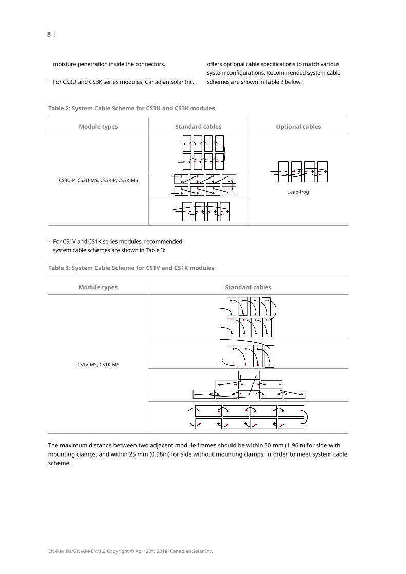
table 2: system Cable scheme for Cs3u and Cs3K modules
The maximum distance between two adjacent module frames should be within 50 mm (1.96in) for side with mounting clamps, and within 25 mm (0.98in) for side without mounting clamps, in order to meet system cablescheme.
moisture penetration inside the connectors.
· For CS3U and CS3K series modules, Canadian Solar Inc.
offers optional cable specifications to match various system configurations. Recommended system cable schemes are shown in Table 2 below:
· For CS1V and CS1K series modules, recommended system cable schemes are shown in Table 3:
table 3: system Cable scheme for Cs1v and Cs1K modules
module types standard cables
CS1V-MS, CS1K-MS

www.canadiansolar.com
| 9
CoRReCt ConneCtIon of PluG ConneCtoRs
· Make sure that all connections are safe and properly mated. The PV connector should not be subjected to stress from the exterior. Connectors should only be used to connect the circuit. They should never be used to turn the circuit on and off.
· Connectors are not waterproof when unmated. When installing modules, connector should be connected to each other as soon as possible or appropriate measures should be taken to avoid moisture and dust penetrating into the connector.
use of suItaBle mateRIals
· Only use dedicated solar cable and suitable connectors (wiring should be sheathed in a sunlight-resistant conduit or, if exposed, should be sunlight-resistant itself) that meet local fire, building and electrical regulations. Please ensure that all wiring is in perfect electrical and mechanical condition.
· Installers may only use single-conductor cable listed and labeled as USE-2 or PV wire which is 90°C wet rated in North America, and single conductor cable, 2.5-16 mm² (5-14 AWG ), 90°C wet rated in other areas (i.e. TUV 2PfG1169 or EN50618 approved), with proper insulation which is able to withstand the maximum possible system open-circuit voltage.
· Only copper conductor material should be used.
Select a suitable conductor gauge to minimize voltage drop and ensure that the conductor ampacity complies with local regulations (i.e. NEC 690.8(D)).
CaBle anD ConneCtoR PRoteCtIon
· Secure the cables to the mounting system using UV-resistant cable ties. Protect exposed cables from damage by taking appropriate precautions (e.g. placing them inside a metallic raceway like EMT conduit). Avoid exposure to direct sunlight.
· A minimum bending radius of 60 mm (2.36 in) is required when securing the junction box cables to the racking system.
· Do not place connectors in locations where water could easily accumulate.
5.2 GRounDInG
· For grounding requirements in North America, a module with exposed conductive parts is considered to comply with UL 1703 only when it is electrically grounded in accordance with both the instructions presented below and the requirements of the National Electrical Code. Any grounding means used with Canadian Solar Inc. modules should be NRTL certified to UL 467 and UL 2703 standards. Please consult our technical service team for the formal approval process.
· For grounding requirements in other areas, although the modules are certified to Safety Class II, we recommend them to be grounded and that module installation should comply with all applicable local electrical codes and regulations.
· Grounding connections should be installed by a qualified electrician.
· Connect module frames together using adequate grounding cables: we recommend using 4-14 mm² (AWG 6-12) copper wire. Holes provided for this purpose are identified with a grounding symbol
(IEC 61730-1). All conductive connection junctions must be firmly fixed.
· Do not drill any extra ground holes for convenience this will void the modules warranty.
· All bolts, nuts, flat washers, lock washers and other relevant hardware should be made of stainless steel, unless otherwise specified.
· Canadian Solar Inc. does not provide grounding hardware.
· One grounding method is recommended for Canadian Solar Inc. standard modules, as described below. For alternative grounding methods, please refer to Annex B (Alternative Grounding Methods) on the website (www.canadiansolar.com). It is not possible to use standard grounding methods for certain module ranges. Please refer to Annex B for more details.

EN-Rev IM/GN-AM-EN/1.3 Copyright © Apr. 20th, 2018. Canadian Solar Inc.
10 |
1. To fix the wire between the flat washer and cup washer, place the cup washer (concave side up) between the frame and the wire.
2. Then tighten the bolt using the toothed nut.
· A grounding kit containing an M5 (3/16") SS cap bolt, an M5 (3/16") SS flat washer, an M5 (3/16") SS cup washer, and an M5 (3/16") SS nut (with teeth) is used to attach copper grounding wire to a pre-drilled grounding hole on the frame (see image below).
· Place the wire between the flat washer and the cup washer. Ensure that the cup washer is positioned between the frame and the wire with the concave side up to prevent galvanic corrosion. Tighten the bolt securely using the SS toothed nut. A wrench may be used to do this. The tightening torque is 3-7 Nm (2.2-5.2 ft-lbs).
6.0 mountInG InstRuCtIons
The applicable regulations pertaining to work safety, accident prevention and securing the construction site must be
observed. Workers and third party personnel shall wear or install fall arrest equipment. Any third party need to be protected against injuries and damages.
· The mounting design must be certified by a registered professional engineer. The mounting design and procedures must comply with all applicable local codes and requirements from all relevant authorities.
· The module is considered to be in compliance with UL 1703 and IEC 61215 only when the module is mounted in the manner specified by the mounting instructions included in this installation manual.
· Any module without a frame (laminate) shall not be considered to comply with the requirements of UL
1703 unless the module is mounted with hardware that has been tested and evaluated with the module under this standard or by a field inspection certifying that the installed module complies with the requirements of UL 1703.
· Canadian Solar Inc. does not provide mounting hardware.
· Standard modules can be mounted onto a support structure using one of several approved methods. One of such methods is described below. For details of other mounting methods and the methods recommended by Canadian Solar Inc. for special module ranges, please refer to the Annex A (Alternative Mounting Methods) on our website (www.canadiansolar.com). For information about other installation methods, please contact your local representative. Failure to use a recognized installation method will void the Canadian Solar Inc. warranty.
· Use appropriate corrosion-proof fastening materials. All mounting hardware (bolts, spring washers, flat washers, nuts) should be hot dip galvanized or stainless steel.
· Use a torque wrench for installation.
· Do not drill additional holes or modify the module frame. Doing so will void the warranty.
· Standard modules can be installed in either landscape or portrait orientations. Refer to the detailed instructions for further guidance. Please note that in areas with heavy snowfall (> 2400 Pa) further countermeasures such the use of additional support bars should be considered to avoid snow loads damaging the lowest row of modules.
GRounDInG metHoD: Bolt + tootHeD nut + CuP WasHeR.

www.canadiansolar.com
| 11
· In cases where an additional support bar is recommended to improve both mechanical stability and long-term module performance, we recommend selecting a sufficiently resistant material. Canadian Solar Inc. recommends bars with a minimum thickness of 50 mm (1.97 in). The support bar centerline should be positioned within 100 mm (3.94 in) of the side frame centerline (slight shifts may be necessary to access module grounding holes).
· The loads described in this manual correspond to test loads. For installations complying with IEC 61215-2: 2016 and UL 1703, a safety factor of 1.5 should be applied for calculating the equivalent maximum authorized design loads. Project design loads depend on construction, applicable standards, location and local climate. Determination of the design loads is the responsibility of the racking suppliers and / or professional engineers. For detailed information, please follow local structural code or contact your professional structural engineer.
6.1 mountInG metHoD: BoltInG
· This mounting method has been qualified by Canadian Solar Inc. as well as certified by VDE. and CSA.
· Modules should be bolted to supporting structures through the mounting holes in the rear frame flanges only.
· Each module must be securely fastened at a minimum of 4 points on two opposite sides.
M8 X 1.25 - Grade 8.8 (5/16”-18 Grade B7)
galvanized or A2-70 stainless steel bolt and nut should be used.
The yield strength of bolt and nut should not be less than 450 MPa.
· Tightening torques should be within 6~12 Nm (4.4~8.9 ft-lbs) and 17~23 Nm (12.5~17.0 ft-lbs) respectively for M6 (1/4”-20) and M8 (5/16”-18) coarse thread bolts, depending on bolt class.
· In areas with heavy wind loads, additional mounting points should be used. The system
designer and the installer are responsible for correctly calculating the loads and ensuring that the supporting structure meets all the applicable requirements.
mounting method: Bolting
· Modules should be bolted at the following hole locations depending on the configuration and loads:
Bolt
Frame
NutSpringWasher
Washer
Washer
Rail

EN-Rev IM/GN-AM-EN/1.3 Copyright © Apr. 20th, 2018. Canadian Solar Inc.
12 |
table 3-1: approved bolting methods
Bolting on short frame side using four standard mounting holes. Mounting rails run parallel to the long frame side.
Maximum Load: Uplift load ≤ 2400 PaDownforce load ≤ 2400 Pa
Compatible module types: CS6A-P, CS6A-M and CS6A-MS
Bolting on short frame side using four standard mounting holes. Mounting rails run perpendicularly to the long frame side. An additional support bar should be placed below the module as shown below.
Maximum Load: Uplift load ≤ 2400 PaDownforce load ≤ 5400 Pa
Compatible module types: CS6A-P, CS6A-M and CS6A-MS
Bolting on long frame side using four innermost mounting holes. Mounting rails run perpendicularly to the long frame side.
Maximum Load: Uplift load ≤ 2400 PaDownforce load ≤ 5400 Pa
Compatible module types: CS1V-MS, CS1K-MS, CS3K-P, CS3K-MS, CS6A-P, CS6A-M, CS6V-P, CS6V-M, CS6K-P, CS6K-M, CS6K-MS, CS6V-MS, CS6VL-MS and CS6A-MS
Bolting on long frame side using four innermost mounting holes. Mounting rails run parallel to the long frame side.
Maximum Load:Uplift load ≤ 2400 Pa Downforce load ≤4000 Pa
Compatible module types: CS1V-MS, CS1K-MS, CS3K-P, CS3K-MS, CS6A-P, CS6A-M, CS6A-MS, CS6V-P, CS6V-M, CS6V-MS, CS6K-P, CS6K-M, CS6K-MS
Bolting on long frame side using four middle mounting holes. Mounting rails run perpendicularly to the long frame side.
Maximum Load: Uplift load ≤ 2400 PaDownforce load ≤ 5400 Pa
Compatible module types: CS3U-P, CS3U-MS, CS6U-P and CS6U-M
Support bar
Bolting on long frame side using four middle mounting holes. Mounting rails run parallel to the long frame side.
Maximum Load:Uplift load ≤ 2400 PaDownforce load ≤5400 Pa
Compatible module types: CS3U-P, CS3U-MS, CS6U-P and CS6U-M
www.canadiansolar.com
| 13
· Do not make modifications to any components of the PV module (diode, junction box, plug connectors or others).
· Regular maintenance is required to keep modules clear of snow, bird droppings, seeds, pollen, leaves, branches, dirt spots, and dust.
· Modules with sufficient tilt (at least 15°), generally may not require cleaning (rain will have a self-cleaning effect). If the module has become soiled, wash with water and a non-abrasive cleaning implement (sponge) during the cool part of the day. Do not scrape or rub dry dirt away, as this may cause micro scratches.
· Snow should be removed using a soft brush.
· Periodically inspect the system to check the integrity of all wiring and supports.
· To protect against electric shock or injury, electrical or mechanical inspections and maintenance should be performed by qualified personnel only.
· Please refer to Annex D (Module Cleaning Guide) for additional information on this topic.
amenDeD eDItIons anD Dates
7.0 maIntenanCe
CanaDIan solaR InC.545 Speedvale Avenue West, Guelph, Ontario, Canada N1K 1E6www.canadiansolar.com
· The first edition Rev 1.0 was released in June, 2017.· The Second edition Rev 1.1 was released in October, 2017.· The Third edition Rev 1.2 was released in April 11th, 2018.· The Forth edition Rev 1.3 was released in April 20th, 2018.

INSTALLATIONMANUAL ANNEXOF STANDARD SOLAR MODULES
For professional use only

EN-Rev IM/GN-AM-EN/A11 Copyright © Apr. 20th, 2018. Canadian Solar Inc.
ANNEX A: ALTERNATIvE MOUNTINg METhODS
MOUNTINg METhOD A: CLAMpINg
MOUNTINg METhOD B: INSERTION SySTEMS
MOUNTINg METhOD C: CENTER MOUNTINg METhOD wITh ThIRD pARTy TRACkER
|3
|3
|13
|16
ANNEX B: ALTERNATIvE gROUNDINg METhODS |16
ANNEX C: MEChANICAL AND ELECTRICAL RATINgS |18
ANNEX D: MODULE CLEANINg gUIDELINES |23
AMENDED EDITIONS AND DATES |24
INSTALLATION MANUAL DISCLAIMER
The information contained in this manual is subject to change by Canadian Solar Inc. without prior notice. Canadian Solar Inc. gives no warranty of any kind whatsoever, either explicitly or implicitly, with respect to the information contained herein.
In the event of any inconsistency among different language versions of this document, the English version shall prevail. Please refer to our product lists and documents published on our website at: http://www.canadiansolar.com as these lists are updated on a regular basis.
2 |

www.canadiansolar.com
All the basic requirements of the main installation manual should apply to the alternative mounting methods, unless otherwise specified.
The loads described in this manual corresponds to test loads. For installations complying with IEC 61215-2: 2016 and UL 1703, a safety factor of 1.5 should be applied for calculating the equivalent maximum authorized design loads.
Project design loads depend on construction, applicable standards, location and local climate. Determination of the design loads is the responsibility of the racking suppliers or professional engineers. For detailed information, please follow local structural code or contact your professional structural engineer.
MOUNTINg METhOD A CLAMpINg
· The mounting method has been qualified by Canadian Solar Inc. as well as certified by VDE and CSA.
· Top or bottom clamping methods will vary and are dependent on the mounting structures. Please follow the mounting guidelines recommended by the mounting system supplier.
· Each module must be securely fastened at a minimum of four points on two opposite sides. The clamps should be positioned symmetrically. The clamps should be positioned according to the authorized position ranges defined in table A.
· Install and tighten the module clamps to the mounting rails using the torque stated by the mounting hardware manufacturer. M8 X 1.25 (5/16”) bolt and nut are used for this clamping method.
· Tightening torques should be within 17~23 Nm (12.5~17.0 ft-lbs) for M8 (5/16”) coarse thread bolts, depending on the bolt class. For the bolt grade, the technical guideline from the fastener suppliers should be followed. Different recommendations from specific clamping hardware suppliers should prevail.
· The system designer and installer are responsible
for load calculations and for proper design of support structure.
· Canadian Solar Inc.’s warranty may be void in cases where improper clamps or unsuitable installation methods are found. When installing inter-modules or end-type clamps, please take the following measures into account:
Do not bend the module frame. Do not touch or cast shadows on the front glass. Do not damage the surface of the frame (to the exception of the clamps with bonding pins). Ensure the clamps overlap the module frame by at least 5 mm (0.2 in) Ensure the clamps overlap length is at least 40 mm (1.57 in) Ensure the clamp’s thickness is at least 3 mm (0.12 in).
· Clamp material should be anodized aluminum alloy or stainless steel.
· Clamp positions are of crucial importance for the reliability of the installation. The clamp centerlines must only be positioned within the ranges indicated in table A, depending on the configuration and load.
· For configurations where the mounting rails run parallel to the frame, precautions should be taken to ensure the bottom flange of the module frame overlaps the rail by 15 mm (0.59 in) or more.
ANNEX A: ALTERNATIvE MOUNTINg METhODS
Min. 5 mm overlap
Min. 3 mm thickness
Min. overlap length 40 mm
6
| 3

EN-Rev IM/GN-AM-EN/A11 Copyright © Apr. 20th, 2018. Canadian Solar Inc.
4 |
Table ACS3U-p, CS3U-MS, CS6U-p and CS6U-M
Use four clamps on the long side. Mounting rails run perpendicularly to the long side frame.
A1
A1 A1
A1
A1 range = (410 – 490) mmMaximum Load: Uplift load ≤ 3600 PaDownforce load ≤ 5400 Pa
A1 range = (340 – 550) mmMaximum Load: Uplift load ≤ 2400 PaDownforce load ≤ 2400 Pa
Min. 15 mm overlap width
Clamp
Rail
Module frame
A1
A1
Use two clamps on the long side and two clamps on the short side. Mounting rails run perpendicular to the long side frame.
A1 range = (300 – 550) mmA2 range = (200 – 250) mmMaximum Load: Uplift load ≤ 2400 PaDownforce load ≤ 2400 Pa
A2
A2

www.canadiansolar.com
| 5
CS3k-p, CS3k-MS, CS6k-p, CS6k-M, CS6k-MS
Use four clamps on the long side. Mounting rails run perpendicularly to the long side frame.
Use four clamps on the short side. Mounting rails run parallel to the long side frame.
A1 range = (0 – 239) mmMaximum Load: Uplift load ≤ 2000 PaDownforce load ≤ 2000 Pa
A2 range = (200 – 250) mmMaximum Load: Uplift load ≤ 2000 PaDownforce load ≤ 2000 Pa
A1 range = (331 – 550) mmMaximum Load: Uplift load ≤ 2400 PaDownforce load ≤ 2400 Pa
A1
A1 A1
A1
A1 range = (240 – 330) mmMaximum Load: Uplift load ≤ 3600 PaDownforce load ≤ 5400 Pa
A2
A2
A2
A2
A1
A1 A1
A1
Use four clamps on the long side. Mounting rails run parallel to the long side frame.
A1 range = (410 – 490) mmMaximum Load: Uplift load ≤ 2400 PaDownforce load ≤ 5400 Pa
A2
A2A2
A2
Use four clamps on the short side and two clamps on the long side. An additional support bar should be placed below the center of the module.
A2 range = (200 – 250) mmMaximum Load: Uplift load ≤ 2400 PaDownforce load ≤ 5400 Pa

EN-Rev IM/GN-AM-EN/A11 Copyright © Apr. 20th, 2018. Canadian Solar Inc.
6 |
Use four clamps on the short side.
A2
A2A2
A2 A2
A2A2
A2
A2 range = (0 – 250) mmMaximum Load: Uplift load ≤ 2000 PaDownforce load < 2000 Pa
A2 range = (200 – 250) mmMaximum Load: Uplift load ≤ 2400 PaDownforce load ≤ 5400 Pa
Use four clamps on the short side and two clamps on the long side. An additional support bar should be placed below the center of the module.
Use four clamps on the long side. Mounting rails run parallel to the long side frame.
A1 range = (240 – 330) mmMaximum Load: Uplift load ≤ 2400 PaDownforce load ≤ 4000 Pa
A1
A1 A1
A1 A3
A3 A5
A5
Use six clamps on the long side. Mounting rails run perpendicularly to the long side frame.
A3 range = (80 –280) mm, A5 range = (80 –280) mmMaximum Load: Uplift load ≤ 4000 PaDownforce load ≤ 6000 Pa
A4A4
A4A4
A1
A1Use two clamps on the long side and two clamps on the short side.Mounting rails run perpendicular to the long side frame.
A1 range = (100 – 550) mmA2 range = (200 – 250) mmMaximum Load: Uplift load ≤ 2400 PaDownforce load ≤ 2400 Pa
A2
A2

www.canadiansolar.com
| 7
Landscape installation, clamping on long side frame.
Mounting Orientation Max Span Max Cantilever length Downforce Uplift
Landscape
72 inches (1.83 m) 24 inches (0.61 m) 2200 Pa 1400 Pa
64 inches (1.63 m) 21.3 inches (0.54 m) 2400 Pa 1400 Pa
48 inches (1.22 m) 16 inches (0.41 m) 3400 Pa 1800 Pa
32 inches (0.81 m) 10.7 inches (0.27 m) 5400 Pa 2400 Pa
Cantilever Span Span Cantilever
Rafter24 inches(0.61 m)
Support Clamp
Interlock
portrait installation, clamping on short side frame.
Mounting Orientation Max Span Max Cantilever length Downforce Uplift
Portrait
48 inches (1.22 m) 16 inches (0.41 m) 1800 Pa 800 Pa
32 inches (0.81 m) 10.7 inches (0.27 m) 1800 Pa 1200 Pa
24 inches (0.61 m) 8 inches (0.2 m) 1800 Pa 1800 Pa
Cantilever Span Cantilever
Rafter24 inches(0.61 m)
Support Clamp
Interlock
Rail-less clamping for CS3k-p, CS3k-MS, CS6k-p, CS6k-M, CS6k-MS

EN-Rev IM/GN-AM-EN/A11 Copyright © Apr. 20th, 2018. Canadian Solar Inc.
8 |
CS1k-MS
Use four clamps on the long side. Mounting rails run perpendicularly to the long side frame.
A1 range = (0 – 239) mmMaximum Load: Uplift load ≤ 2000 PaDownforce load ≤ 2000 Pa
A1
A1 A1
A1
A1 range = (240 – 550) mmMaximum Load: Uplift load ≤ 2400 PaDownforce load ≤ 2400 Pa
A1 range = (240 – 330) mmMaximum Load: Uplift load ≤ 2400 PaDownforce load ≤ 5400 Pa
Use four clamps on the long side. Mounting rails run parallel to the long side frame.
A1
A1 A1
A1
A1 range = (240 – 330) mmMaximum Load: Uplift load ≤ 2400 PaDownforce load ≤ 4000 Pa
CS6A-p, CS6A-M, CS6vL-MS and CS6A-MS
Use four clamps on the long side. Mounting rails run perpendicularly to the long side frame.
Use four clamps on the short side. Mounting rails run parallel to the long side frame.
A1 range = (0 – 219) mmMaximum Load: Uplift load ≤ 2000 PaDownforce load ≤ 2000 Pa
A2 range = (200 – 250) mmMaximum Load: Uplift load ≤ 2400 PaDownforce load ≤ 2400 Pa
A1
A1 A1
A1
A1 range = (220 – 440) mmMaximum Load: Uplift load ≤ 2400 PaDownforce load ≤ 2400 Pa
A1 range = (270 – 330) mmMaximum Load: Uplift load ≤ 2400 PaDownforce load ≤ 5400 Pa
A2
A2
A2
A2

www.canadiansolar.com
| 9
Use four clamps on the short side. Use four clamps on the short side and two clamps on the long side. An additional support bar should be placed below the center of the module.
A2
A2A2
A2A2
A2A2
A2
A2 range = (0 – 250) mmMaximum Load: Uplift load ≤ 2400 PaDownforce load ≤ 2400 Pa
A2 range = (200 – 250) mmMaximum Load: Uplift load ≤ 2400 PaDownforce load ≤ 5400 Pa
Use four clamps on the long side. Mounting rails run parallel to the long side frame.
A1
A1 A1
A1
A1 range = (270 – 330) mmMaximum Load: Uplift load ≤ 2400 PaDownforce load ≤ 4000 Pa
A3
A3 A5
A5
Use six clamps on the long side. Mounting rails run perpendicularly to the long side frame.
A3 range = (80 –380) mmA5 range = (80 –380) mmMaximum Load: Uplift load ≤ 4000 PaDownforce load ≤ 6000 Pa
A4A4
A4A4

EN-Rev IM/GN-AM-EN/A11 Copyright © Apr. 20th, 2018. Canadian Solar Inc.
10 |
CS6v-p, CS6v-M and CS6v-MS
Use four clamps on the long side. Mounting rails run perpendicularly to the long side frame.
Use four clamps on the short side. Mounting rails run parallel to the long side frame.
A1 range = (0 – 239) mmMaximum Load: Uplift load ≤ 2000 PaDownforce load ≤ 2000 Pa
A2 range = (170 – 210) mmMaximum Load: Uplift load ≤ 2400 PaDownforce load ≤ 2400 Pa
A1
A1 A1
A1
A1 range = (240 – 550) mmMaximum Load: Uplift load ≤ 2400 PaDownforce load ≤ 2400 Pa
A1 range = (240 – 330) mmMaximum Load: Uplift load ≤ 2400 PaDownforce load ≤ 5400 Pa
A2
A2
A2
A2
Use four clamps on the short side. Use four clamps on the short side and two clamps on the long side. An additional support bar should be placed below the center of the module.
A2 range = (0 – 210) mmMaximum Load: Uplift load ≤ 2000 PaDownforce load ≤ 2000 Pa
A2 range = (170 – 210) mmMaximum Load: Uplift load ≤ 2400 PaDownforce load ≤ 5400 Pa
A2
A2A2
A2A2
A2A2
A2
www.canadiansolar.com
| 11
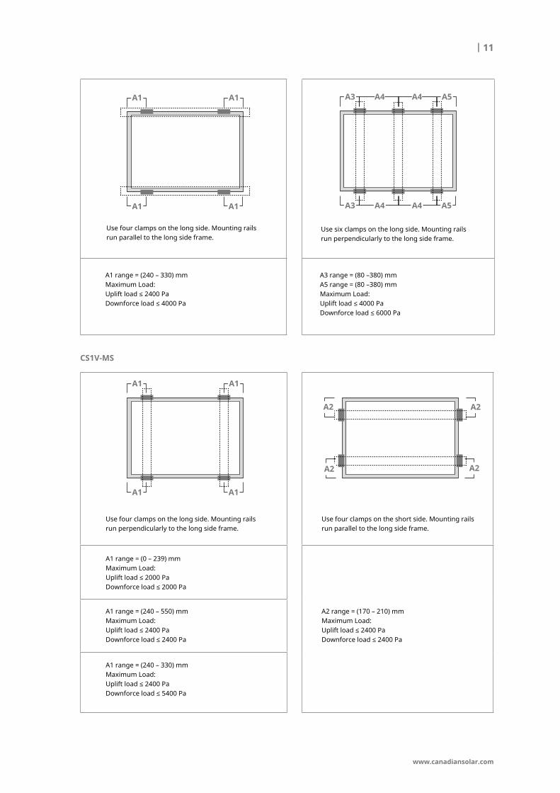
Use four clamps on the long side. Mounting rails run parallel to the long side frame.
A1
A1 A1
A1
A1 range = (240 – 330) mmMaximum Load: Uplift load ≤ 2400 PaDownforce load ≤ 4000 Pa
A3
A3 A5
A5
Use six clamps on the long side. Mounting rails run perpendicularly to the long side frame.
A3 range = (80 –380) mmA5 range = (80 –380) mmMaximum Load: Uplift load ≤ 4000 PaDownforce load ≤ 6000 Pa
A4A4
A4A4
CS1v-MS
Use four clamps on the long side. Mounting rails run perpendicularly to the long side frame.
Use four clamps on the short side. Mounting rails run parallel to the long side frame.
A1 range = (0 – 239) mmMaximum Load: Uplift load ≤ 2000 PaDownforce load ≤ 2000 Pa
A2 range = (170 – 210) mmMaximum Load: Uplift load ≤ 2400 PaDownforce load ≤ 2400 Pa
A1
A1 A1
A1
A1 range = (240 – 550) mmMaximum Load: Uplift load ≤ 2400 PaDownforce load ≤ 2400 Pa
A1 range = (240 – 330) mmMaximum Load: Uplift load ≤ 2400 PaDownforce load ≤ 5400 Pa
A2
A2
A2
A2

EN-Rev IM/GN-AM-EN/A11 Copyright © Apr. 20th, 2018. Canadian Solar Inc.
12 |
Use four clamps on the short side. Use four clamps on the short side and two clamps on the long side. An additional support bar should be placed below the center of the module.
A2 range = (0 – 210) mmMaximum Load: Uplift load ≤ 2000 PaDownforce load ≤ 2000 Pa
A2 range = (170 – 210) mmMaximum Load: Uplift load ≤ 2400 PaDownforce load ≤ 5400 Pa
A2
A2A2
A2A2
A2A2
A2
Use four clamps on the long side. Mounting rails run parallel to the long side frame.
A1
A1 A1
A1
A1 range = (240 – 330) mmMaximum Load: Uplift load ≤ 2400 PaDownforce load ≤ 4000 Pa

www.canadiansolar.com
| 13
MOUNTINg METhOD B: INSERTION SySTEMS
· The mounting method has been qualified by Canadian Solar Inc. as well as certified by VDE and CSA.
· Insertion methods can vary and depend on the mounting structures. The installer needs to follow the mounting guidelines recommended by the mounting system supplier. Each module must be securely maintained through all its length on two opposite sides. Install and tighten the insertion profiles to the support structure using the hardware and instructions provided by the mounting system manufacturer. The system designer and installer are solely responsible for load calculations and for the proper design of support structure.
· Canadian Solar Inc. warranty may be void in cases where improper insertion systems or unsuitable installation methods are found. When installing insertion profiles, please take the following measures into account:
Do not bend the module frame. Do not touch the front glass or cast shadow onto it. Do not damage the surface of the frame. Ensure that the insertion profiles overlap the module frame by at least 10 mm (0.39 in). Ensure that the module frame (C-shape) overlaps the insertion profiles by at least 15 mm (0.59 in). Ensure insertion profile thickness and tolerances suit module thickness.
Min. 10 mm overlap
Min. 15 mm overlap
6
CS3U-p, CS3U-MS, CS6U-p and CS6U-M
Use two insertion profiles running parallel to the long side frame.
Maximum Load:Uplift load ≤ 2400 PaDownforce load ≤ 5400 Pa
Use two insertion profiles running perpendicularly to the long side frame. An additional support bar should be placed below the module. Use two clamps on the support bar.
Maximum Load:Uplift load ≤ 2400 PaDownforce load ≤ 5400 Pa

EN-Rev IM/GN-AM-EN/A11 Copyright © Apr. 20th, 2018. Canadian Solar Inc.
14 |
Use two insertion profiles running parallel to the long side frame.
Use two insertion profiles running perpendicularly to the long side frame.
Maximum Load:Uplift load ≤ 2000 PaDownforce load ≤ 2000 Pa
Maximum Load:Uplift load ≤ 2400 PaDownforce load ≤ 4000 Pa
CS3k-p, CS3k-MS, CS6k-p, CS6k-M, CS6k-MS, CS6v-p, CS6v-M and CS6v-MS
Use two insertion profiles running perpendicularly to the long side frame. An additional support bar should be placed below the module. Use two clamps on the support bar.
Maximum Load:Uplift load ≤ 2400 PaDownforce load ≤ 5400 Pa
Use two insertion profiles running parallel to the long side frame.
Maximum Load:Uplift load ≤ 2400 PaDownforce load ≤ 2400 Pa
Use two insertion profiles running perpendicularly to the long side frame.
Maximum Load:Uplift load ≤ 2400 PaDownforce load ≤ 4000 Pa
CS6A-p, CS6A-M, CS6vL-MS and CS6A-MS

www.canadiansolar.com
| 15
Use two insertion profiles running perpendicularly to the long side frame. An additional support bar should be placed below the module. Use two clamps on the support bar.
Maximum Load:Uplift load ≤ 2400 PaDownforce load ≤ 5400 Pa
Use two insertion profiles running parallel to the long side frame.
Maximum Load:Uplift load ≤ 2400 PaDownforce load ≤ 4000 Pa
CS1k-MS
Use two insertion profiles running perpendicularly to the long side frame. An additional support bar should be placed below the module. Use two clamps on the support bar.
Maximum Load:Uplift load ≤ 2400 PaDownforce load ≤ 5400 Pa
Use two insertion profiles running parallel to the long side frame.
Maximum Load:Uplift load ≤ 2000 PaDownforce load ≤ 2000 Pa
Use two insertion profiles running perpendicularly to the long side frame.
Maximum Load:Uplift load ≤ 2400 PaDownforce load ≤ 4000 Pa
CS1v-MS

EN-Rev IM/GN-AM-EN/A11 Copyright © Apr. 20th, 2018. Canadian Solar Inc.
16 |
MOUNTINg METhOD C: CENTER CLAMp MOUNTINg METhOD wITh (SINgLE-AXIS TRACkER)
· Canadian Solar Inc. modules can be mounted on single-axis trackers using center clamps or mounting holes as described below. All the requirements of the standard module installation manual and specific tracker detailed installation instructions should apply.
· The mounting method has been qualified by Canadian Solar Inc. as well as certified by VDE and CSA.
Mounting Rail
Use two insertion profiles running perpendicularly to the long side frame. An additional support bar should be placed below the module. Use two clamps on the support bar.
Maximum Load:Uplift load ≤ 2400 PaDownforce load ≤ 5400 Pa
Module Type
Compatible Tracker
Mounting hardware Maximum Load (pa) Reference Manual
(version No.)
CS3U-P, CS3U-MS, CS6U-Pand CS6U-M
ATI DuraTrack™HZ Tracking System(V3) Clamp Ear (V3) Uplift load ≤ 2400 Pa
Downforce load ≤ 2400 Pa
DuraTrack™HZ Solar Tracker Installation Guide (January 2017, Rev. B-01)
CS3U-P, CS3U-MS, CS6U-Pand CS6U-M
NEXTracker NX Horizon
400 mm Short Rail (mounting
holes)
Uplift load ≤ 2400 PaDownforce load ≤ 2400 Pa
NEXTracker NX Horizon 2.1.1
Installation Manual (PDM-000103 Rev. A)
· The allowable maximum twist angle of the module is 0.5 degree.
· Please contact the tracker manufacturer and Canadian Solar Inc.’s technical support department for details in regard to specific projects.
Canadian Solar modules can be grounded using third party grounding devices as described below. The grounding methods are certified by CSA according to UL 1703. All the basic requirements of the main installation manual should apply to
the alternative grounding methods. For detailed grounding instructions, please refer to related third party installation manuals.
ANNEX B: ALTERNATIvE gROUNDINg METhODS

www.canadiansolar.com
| 17
Company grounding hardware Compatible Mounting System Reference Manual (version No.)
Variety Lay-in-Lug + Star Washer
(UL 2703 & UL 467 certified)Variety Related reference installation manual
Schletter GmbH
Schletter Rapid2+ Grounding Clamps
Schletter Rapid2+ Schletter Rapid2+ Clamp installation
instructions
Array Technologies
Inc.Grounding Strip ATI Duratrack HZ
Solar Tracker (V3)
DuraTrack™HZ Solar TrackerInstallation Guide (January 2017, Rev.
B-01)
IronRidge Inc. grounding mid clamps (integrated grounding)
standard (XRS) and light (XRL) rails
Standard (XRS) and Light (XRL) Rails with Integrated Grounding Installation
Manual (2013 Edition v1.13)
DYNORAXX Inc.
DynoRaxx® DynoBond spring clips
-----DynoRaxx® DynoBond Installation
Manual (publication no 090413)
RBI Solar Inc.Raised Zee purlin integrated with pre-punched grounding
holes
RBI Solar Ground Mount System Model
GM-I
Ground Mount System Model GM-I Module Installation Manual (14 April 2014, version 21)
Quick Rack PV Inc.
Clamp integrated with grounding pins
Quick Rack Rail-Free Mounting System
Quick Rack Rail-Free Mounting System for Composition/Asphalt Shingle Roofs Installation Manual (May 2014, Rev F)
Cantsink Mfg Inc.
1/4" serrated flange bolt & serrated flange nut
Brilliant Rack Ground Mount System
Brilliant Rack Ground Mount System Installation Manual (Revision
12/05/2014)
Everest Solar Systems, LLC
WEEB-KMC ClipsCrossrail 36, Crossrail
48 And Crossrail 80 Mounting Systems
WEEB Installation Instructions For Everest Solar Crossrail 36, Crossrail 48
And Crossrail 80 Mounting Systems Only (50015303 Rev H)
Unirac Inc. Mid clamp retention teeth SOLAR MOUNT (SM)Solar Mount Installation Guide
(Revision PUB15MAR02)
Sunlink Inc.Center Clamps & End Clamps
with pre-punched teeth
Ballasted Ground Mount System and Core Roof Mount
System
Assembly Instructions for Core RMS (Rev 03-14-2014) and Assembly Instructions for Ballasted GMS
(Rev 02/02/2014)
Roof Tech Inc. Bonding PlateRT-[E] Mount E Mount
AIR RT-[E] Mount E Mount AIR Installation
Manual (March 2015)
NEXTracker Inc.
1/4-in collar and 1/4-in pin NX Horizon 2.2.1NEXTracker NX Horizon 2.2.1 Short Rail Installation Manual (PDM-000103 Rev. )
BURNDY LLC. WEEB-UIR RBI Solar Groundmount
WEEB Installation Instructions For RBI Solar Groundmount Only (104-
0404-000074-003)

EN-Rev IM/GN-AM-EN/A11 Copyright © Apr. 20th, 2018. Canadian Solar Inc.
18 |
Standard Test Conditions are: Irradiance of 1000 W/m2, AM1.5 spectrum, and cell temperature of 25°C. The electrical characteristics are respectively within
±10% or [0; +5 W] of the indicated values for Isc, Voc and Pmax. Specifications are subject to change without notice.
Module TypeMaximum
powerpmax <w>
Operatingvoltage
vmp <v>
OperatingcurrentImp <A>
Open Circuit
voltagevoc <v>
Short Circuit
CurrentIsc <A>
Max. SeriesFuse
Rating <A>
OverallDimension
<mm>
weight<kg>
CS6A-195M 195 24.2 8.04 29.9 8.56 15.00
1324 x 984 x 40(52.1 ˣ 38.7 ˣ
1.57 in)
15.5(34.2 lbs)
CS6A-200M 200 24.3 8.22 30.0 8.74 15.00
CS6A-205M 205 24.5 8.38 30.2 8.90 15.00
CS6A-210M 210 24.6 8.54 30.3 9.06 15.00
CS6A-215M 215 24.7 8.70 30.4 9.22 15.00
CS6A-220M 220 24.8 8.87 30.6 9.31 15.00
CS6A-205MS 205 24.5 8.37 30.6 9.21 15.00
CS6A-210MS 210 24.7 8.50 30.8 9.29 15.00
CS6A-215MS 215 24.9 8.63 31.0 9.37 15.00
CS6A-220MS 220 25.1 8.76 31.2 9.45 15.00
CS6A-225MS 225 25.3 8.91 31.4 9.53 15.00
CS6A-230MS 230 25.5 9.02 31.6 9.61 15.00
CS6A-235MS 235 25.7 9.14 31.8 9.68 15.00
CS6A-240MS 240 25.9 9.27 32.0 9.76 15.00
CS6A-245MS 245 26.1 9.39 32.2 9.84 15.00
CS6A-195p 195 24.0 8.13 29.6 8.69 15.00
1324 x 984 x 40(52.1 ˣ 38.7 ˣ
1.57 in)
15.5(34.2 lbs)
CS6A-200p 200 24.1 8.30 29.8 8.87 15.00
CS6A-205p 205 24.2 8.47 29.9 9.03 15.00
CS6A-210p 210 24.3 8.63 30.0 9.19 15.00
CS6A-215p 215 24.5 8.78 30.2 9.35 15.00
CS6A-220p 220 24.6 8.95 30.4 9.45 15.00
CS6v-200M 200 25.2 7.95 31.1 8.46 15.00
1638 × 826 × 40(64.5 ˣ 32.5 ˣ
1.57 in)
16.0(35.3 lbs)
CS6v-205M 205 25.3 8.11 31.2 8.63 15.00
CS6v-210M 210 25.4 8.27 31.3 8.79 15.00
CS6v-215M 215 25.5 8.43 31.5 8.94 15.00
CS6v-220M 220 25.7 8.56 31.6 9.08 15.00
CS6v-225M 225 26.0 8.67 31.8 9.19 15.00
CS6v-230M 230 26.1 8.81 31.9 9.33 15.00
CS6v-235M 235 26.4 8.91 32.1 9.45 15.00
CS6v-240M 240 26.7 9.00 32.2 9.55 15.00
CS6v-245M 245 27.0 9.09 32.4 9.66 15.00
CS6v-210MS 210 25.4 8.27 31.5 9.19 15.00
CS6v-215MS 215 25.6 8.40 31.7 9.27 15.00
CS6v-220MS 220 25.8 8.53 31.9 9.35 15.00
CS6v-225MS 225 26.0 8.66 32.1 9.43 15.00
CS6v-230MS 230 26.2 8.78 32.3 9.51 15.00
CS6v-235MS 235 26.4 8.91 32.5 9.59 15.00
CS6v-240MS 240 26.6 9.03 32.7 9.67 15.00
CS6v-245MS 245 26.8 9.15 32.9 9.75 15.00
CS6v-250MS 250 27.0 9.26 33.1 9.83 15.00
Table C: Mechanical And Electrical Ratings under STC
ANNEX C: MEChANICAL AND ELECTRICAL RATINgS

www.canadiansolar.com
| 19
Module TypeMaximum
powerpmax <w>
Operatingvoltage
vmp <v>
OperatingcurrentImp <A>
Open Circuit
voltagevoc <v>
Short Circuit
CurrentIsc <A>
Max. SeriesFuse
Rating <A>
OverallDimension
<mm>
weight<kg>
CS6v-255MS 255 27.2 9.38 33.3 9.91 15.00
CS6vh-115MS 115 13.1 8.78 16.2 9.59 15.00844 × 826 × 40
(33.2 ˣ 32.5 ˣ 1.57 in) 9.0
(19.8 lbs) CS6vh-120MS 120 13.3 9.03 16.4 9.67 15.00
CS6vh-125MS 125 13.5 9.26 16.6 9.75 15.00
CS6vL-150MS 150 19.5 7.7 24.6 9.11 15.00
1322 × 826 × 40(52.05 x 32.5 x
1.57 in)
12.6(27.8 lbs)
CS6vL-155MS 155 19.7 7.87 24.8 9.19 15.00
CS6vL-160MS 160 19.9 8.05 25 9.27 15.00
CS6vL-165MS 165 20.1 8.21 25.2 9.35 15.00
CS6vL-170MS 170 20.3 8.38 25.4 9.43 15.00
CS6vL-175MS 175 20.5 8.54 25.6 9.51 15.00
CS6vL-180MS 180 20.7 8.7 25.8 9.59 15.00
CS6vL-185MS 185 20.9 8.86 26 9.67 15.00
CS6vL-190MS 190 21.1 9.01 26.2 9.75 15.00
CS6vL-195MS 195 21.3 9.16 26.4 9.83 15.00
CS6vL-200MS 200 21.5 9.31 26.6 9.91 15.00
CS6vL-205MS 205 21.7 9.45 26.8 9.99 15.00
CS6vL-210MS 210 21.9 9.59 26.9 10.07 15.00
CS6v-190p 190 24.6 7.73 30.6 8.28 15.00
1638 × 826 ×40(64.5 ˣ 32.5 ˣ
1.57 in)
16.0(35.3 lbs)
CS6v-195p 195 24.8 7.87 30.7 8.44 15.00
CS6v-200p 200 24.9 8.03 30.8 8.59 15.00
CS6v-205p 205 25.0 8.19 30.9 8.76 15.00
CS6v-210p 210 25.1 8.35 31.1 8.92 15.00
CS6v-215p 215 25.3 8.51 31.2 9.07 15.00
CS6v-220p 220 25.5 8.64 31.4 9.21 15.00
CS6v-225p 225 25.7 8.75 31.6 9.32 15.00
CS6v-230p 230 25.9 8.90 31.7 9.47 15.00
CS6v-235p 235 26.1 8.99 31.8 9.58 15.00
CS6k-240p 240 29.9 8.03 37.0 8.59 15.00
1650 x 992 x 40 / 35
(65.0 ˣ 39.1 ˣ 1.57 / 1.38 in)
18.2(40.1 lbs)
CS6k-245p 245 30.0 8.17 37.1 8.74 15.00
CS6k-250p 250 30.1 8.30 37.2 8.87 15.00
CS6k-255p 255 30.2 8.43 37.4 9.00 15.00
CS6k-260p 260 30.4 8.56 37.5 9.12 15.00
CS6k-265p 265 30.6 8.66 37.7 9.23 15.00
CS6k-270p 270 30.8 8.75 37.9 9.32 15.00
CS6k-275p 275 31.0 8.88 38.0 9.45 15.00
CS6k-280p 280 31.3 8.95 38.2 9.52 15.00
CS6k-285p 285 31.4 9.06 38.3 9.64 15.00
CS6k-290p 290 31.6 9.18 38.5 9.72 15.00
CS6k-295p 295 31.8 9.28 38.6 9.81 15.00
CS6k-250M 250 30.4 8.22 37.5 8.74 15.00
1650 x 992 x 40 / 35
(65.0 ˣ 39.1 ˣ 1.57 / 1.38 in)
18.2(40.1 lbs)
CS6k-255M 255 30.5 8.35 37.7 8.87 15.00
CS6k-260M 260 30.7 8.48 37.8 8.99 15.00
CS6k-265M 265 30.9 8.61 37.9 9.11 15.00
CS6k-270M 270 31.1 8.67 38.2 9.19 15.00
CS6k-275M 275 31.3 8.80 38.3 9.31 15.00
CS6k-280M 280 31.5 8.89 38.5 9.43 15.00

EN-Rev IM/GN-AM-EN/A11 Copyright © Apr. 20th, 2018. Canadian Solar Inc.
20 |
Module TypeMaximum
powerpmax <w>
Operatingvoltage
vmp <v>
OperatingcurrentImp <A>
Open Circuit
voltagevoc <v>
Short Circuit
CurrentIsc <A>
Max. SeriesFuse
Rating <A>
OverallDimension
<mm>
weight<kg>
CS6k-285M 285 31.7 8.98 38.6 9.51 15.00
1650 x 992 x 40 / 35
(65.0 ˣ 39.1 ˣ 1.57 / 1.38 in)
18.2(40.1 lbs)
CS6k-290M 290 31.9 9.09 38.7 9.59 15.00CS6k-255MS 255 30.7 8.31 37.9 9.11 15.00CS6k-260MS 260 30.9 8.42 38.1 9.19 15.00CS6k-265MS 265 31.1 8.53 38.3 9.27 15.00CS6k-270MS 270 31.3 8.63 38.5 9.35 15.00CS6k-275MS 275 31.5 8.74 38.7 9.43 15.00CS6k-280MS 280 31.7 8.84 38.9 9.51 15.00CS6k-285MS 285 31.9 8.94 39.1 9.59 15.00CS6k-290MS 290 32.1 9.05 39.3 9.67 15.00CS6k-295MS 295 32.3 9.14 39.5 9.75 15.00CS6k-300MS 300 32.5 9.24 39.7 9.83 15.00CS6k-305MS 305 32.7 9.33 39.9 9.91 15.00CS6U-290p 290 35.9 8.08 44.4 8.64 15.00
1960 × 992 × 40 / 35
(77.2 ˣ 39.1 ˣ 1.57 / 1.38 in)
22.4(49.4 lbs)
CS6U-295p 295 36.0 8.19 44.5 8.76 15.00CS6U-300p 300 36.1 8.30 44.6 8.87 15.00CS6U-305p 305 36.3 8.41 44.8 8.97 15.00CS6U-310p 310 36.4 8.52 44.9 9.08 15.00CS6U-315p 315 36.6 8.61 45.1 9.18 15.00CS6U-320p 320 36.8 8.69 45.3 9.26 15.00CS6U-325p 325 37.0 8.78 45.5 9.34 15.00CS6U-330p 330 37.2 8.88 45.6 9.45 15.00CS6U-335p 335 37.4 8.96 45.8 9.54 15.00CS6U-340p 340 37.6 9.05 45.9 9.62 15.00CS6U-345p 345 37.8 9.13 46.0 9.69 15.00CS6U-350p 350 38.1 9.21 46.2 9.79 15.00CS6U-290M 290 36.3 8.00 44.7 8.51 15.00
1960 × 992 × 40 / 35
(77.2 ˣ 39.1 ˣ 1.57 / 1.38 in)
22.4(49.4 lbs)
CS6U-295M 295 36.4 8.11 44.9 8.63 15.00CS6U-300M 300 36.5 8.22 45 8.74 15.00CS6U-305M 305 36.6 8.33 45.2 8.84 15.00CS6U-310M 310 36.7 8.44 45.3 8.95 15.00CS6U-315M 315 36.9 8.53 45.5 9.04 15.00CS6U-320M 320 37.2 8.61 45.6 9.13 15.00CS6U-325M 325 37.4 8.69 45.8 9.21 15.00CS6U-330M 330 37.5 8.8 45.9 9.31 15.00CS6U-335M 335 37.8 8.87 46.1 9.41 15.00CS6U-340M 340 37.9 8.97 46.2 9.48 15.00CS6U-345M 345 38.1 9.06 46.4 9.56 15.00CS6U-350M 350 38.3 9.14 46.6 9.67 15.00CS3U-350MS 350 38.8 9.03 46.6 9.53 30
2000 × 992 × 40 / 35
(78.7 ˣ 39.1 ˣ 1.57 / 1.38 in)
22.6 / 22.5(49.8 / 49.6
lbs)
CS3U-355MS 355 39 9.11 46.8 9.61 30CS3U-360MS 360 39.2 9.19 47 9.69 30CS3U-365MS 365 39.4 9.27 47.2 9.77 30CS3U-370MS 370 39.6 9.35 47.4 9.85 30CS3U-375MS 375 39.8 9.43 47.6 9.93 30CS3U-380MS 380 40 9.5 47.8 10.01 30CS3U-385MS 385 40.2 9.58 48 10.09 30

www.canadiansolar.com
| 21
Module TypeMaximum
powerpmax <w>
Operatingvoltage
vmp <v>
OperatingcurrentImp <A>
Open Circuit
voltagevoc <v>
Short Circuit
CurrentIsc <A>
Max. SeriesFuse
Rating <A>
OverallDimension
<mm>
weight<kg>
CS3U-390MS 390 40.4 9.66 48.2 10.17 30
CS3U-395MS 395 40.6 9.73 48.4 10.25 30
CS3U-400MS 400 40.8 9.81 48.6 10.33 30
CS3U-405MS 405 41 9.88 48.8 10.41 30
CS3U-410MS 410 41.2 9.96 49 10.49 30
CS3U-310p 310 37.2 8.34 44.7 8.88 30
2000 × 992 × 40 / 35
(78.7 ˣ 39.1 ˣ 1.57 / 1.38 in)
22.6 / 22.5(49.8 / 49.6
lbs)
CS3U-315p 315 37.4 8.43 44.9 8.96 30
CS3U-320p 320 37.6 8.52 45.1 9.04 30
CS3U-325p 325 37.8 8.6 45.3 9.12 30
CS3U-330p 330 38 8.69 45.5 9.2 30
CS3U-335p 335 38.2 8.77 45.7 9.28 30
CS3U-340p 340 38.4 8.86 45.9 9.36 30
CS3U-345p 345 38.6 8.94 46.1 9.44 30
CS3U-350p 350 39.2 8.94 46.6 9.51 30
CS3U-355p 355 39.4 9.02 46.8 9.59 30
CS3U-360p 360 39.6 9.10 47.0 9.67 30
CS3U-365p 365 39.8 9.18 47.2 9.75 30
CS3U-370p 370 40.0 9.26 47.4 9.83 30
CS3k-280MS 280 31.7 8.84 38.5 9.49 30
1675 x 992 x 40 / 35
(65.9 ˣ 39.1 ˣ 1.57 / 1.38 in)
18.5(40.8 lbs)
CS3k-285MS 285 31.9 8.94 38.7 9.57 30
CS3k-290MS 290 32.1 9.04 38.9 9.65 30
CS3k-295MS 295 32.3 9.14 39.1 9.73 30
CS3k-300MS 300 32.5 9.24 39.3 9.82 30
CS3k-305MS 305 32.7 9.33 39.5 9.9 30
CS3k-310MS 310 32.9 9.43 39.7 9.98 30
CS3k-315MS 315 33.1 9.52 39.9 10.06 30
CS3k-320MS 320 33.3 9.61 40.1 10.14 30
CS3k-325MS 325 33.5 9.71 40.3 10.22 30
CS3k-330MS 330 33.7 9.8 40.5 10.3 30
CS3k-250p 250 30 8.34 36.7 8.98 30
1675 x 992 x 40 / 35
(65.9 ˣ 39.1 ˣ 1.57 / 1.38 in)
18.5(40.8 lbs)
CS3k-255p 255 30.2 8.45 36.9 9.06 30
CS3k-260p 260 30.4 8.56 37.1 9.14 30
CS3k-265p 265 30.6 8.66 37.3 9.22 30
CS3k-270p 270 30.8 8.77 37.5 9.3 30
CS3k-275p 275 31 8.88 37.7 9.38 30
CS3k-280p 280 31.2 8.98 37.9 9.47 30
CS3k-285p 285 31.4 9.08 38.1 9.56 30
CS3k-290p 290 32.3 8.98 38.9 9.49 30
CS3k-295p 295 32.5 9.08 39.1 9.57 30
CS3k-300p 300 32.7 9.18 39.3 9.65 30
CS3k-305p 305 32.9 9.28 39.5 9.73 30
CS3k-310p 310 33.1 9.37 39.7 9.81 30
CS3k-315p 315 33.3 9.46 39.9 9.89 30
CS3k-320p 320 33.5 9.56 40.1 9.97 30
CS3k-325p 325 33.7 9.65 40.3 10.05 30

EN-Rev IM/GN-AM-EN/A11 Copyright © Apr. 20th, 2018. Canadian Solar Inc.
22 |
Module TypeMaximum
powerpmax <w>
Operatingvoltage
vmp <v>
OperatingcurrentImp <A>
Open Circuit
voltagevoc <v>
Short Circuit
CurrentIsc <A>
Max. SeriesFuse
Rating <A>
OverallDimension
<mm>
weight<kg>
CS1v-240MS 240 28.3 8.48 34.7 9.15 15
1638x826x40(64.5 x 32.5 x
1.57 in)
15.4(34.0 lbs)
CS1v-245MS 245 28.6 8.58 34.9 9.22 15
CS1v-250MS 250 28.8 8.68 35.1 9.29 15
CS1v-255MS 255 29.0 8.79 35.3 9.37 15
CS1v-260MS 260 29.2 8.89 35.5 9.44 15
CS1v-265MS 265 29.4 9.00 35.7 9.51 15
CS1v-270MS 270 29.6 9.11 35.9 9.59 15
CS1v-275MS 275 29.8 9.22 36.1 9.66 15
CS1k-285MS 285 29.1 9.80 35.6 10.64 20
1710x992x40(67.3 x 39.1 x
1.57 in)
18.9(41.7 lbs)
CS1k-290MS 290 29.3 9.89 35.8 10.72 20
CS1k-295MS 295 29.5 9.98 35.9 10.81 20
CS1k-300MS 300 29.8 10.08 36.1 10.89 20
CS1k-305MS 305 30.0 10.17 36.3 10.97 20
CS1k-310MS 310 30.2 10.27 36.5 11.06 20
CS1k-315MS 315 30.3 10.39 36.6 11.14 20
CS1k-320MS 320 30.5 10.49 36.8 11.23 20
CS1k-325MS 325 30.7 10.59 37.0 11.31 20
CS1k-330MS 330 30.9 10.69 37.1 11.40 20
CS1k-335MS 335 31.1 10.79 37.3 11.48 20
CS1k-340MS 340 31.2 10.89 37.5 11.57 20
CS1k-345MS 345 31.4 10.99 37.7 11.66 20

www.canadiansolar.com
| 23
ANNEX D: MODULE CLEANINg gUIDELINE
This manual covers requirements for the cleaning procedure of Canadian Solar Inc. photovoltaic modules. The purpose of these cleaning guidelines is to provide general information for cleaning Canadian Solar modules. Professional installers should read these guidelines carefully and strictly follow these instructions.
Failure to follow these instructions may result in death, injury or property damage to the photovoltaic module. Damages induced by inappropriate cleaning procedures will void Canadian Solar Inc. warranty.
SAFETy wARNINg
· Cleaning activities create risk of damaging the modules and array components, as well as increasing the potential electric shock hazard.
· Cracked or broken modules represent an electric shock hazard due to leakage currents, and the risk of shock is increased when modules are wet.
Before cleaning, thoroughly inspect modules for cracks, damage, and loose connections.
· The voltage and current present in an array during daylight hours are sufficient to cause a lethal electrical shock.
· Do not immerse the module, partially or totally, in water or any other cleaning solution.
· Ensure that the circuit is disconnected before starting the cleaning procedure as contact with leakage of electrically active parts can result in injury.
· Ensure that the array has been disconnected from other active components (such as inverter or combiner boxes) before starting with the cleaning.
· Wear suitable protection (clothes, insulated gloves, etc.).
hANDLINg NOTICE
· Use a proper cleaning solution and suitable
cleaning equipment.
· Do not use abrasive or electric cleaners on the module.
· Particular attention should be taken to avoid the module backsheet or frame to come in contact with sharp objects, as scratches may directly affect product safety.
· Do not use de-greasers on the module.
· Do not use cleaning corrosive solutions containing acid, alkali, acetone, or industrial alcohol.
· Canadian Solar Inc. recommends to avoid rotating brush cleaning methods, as they could create micro-cracks in the PV modules.
· Dirt must never be scraped or rubbed away when dry, as this will cause micro-scratches on the glass surface.
OpERATION pREpARATION
· Noticeable dirt must be rubbed away by gentle cleaning-implement (soft cloth, sponge or brush with soft bristles).
· Ensure that brushes or agitating tools are not abrasive to glass, EPDM, silicone, aluminum, or steel.
· Conduct the cleaning activities avoiding the hottest hours of the day, in order to avoid thermal stress on the module.
We recommend the following to be used:· Water with low mineral content· Near neutral pH water· The maximum water pressure recommended is 4 MPa (40 bar)
CLEANINg METhODS
Method A: Compressed AirCanadian Solar Inc. recommends cleaning the soft dirt (like dust) on modules just with compressed

air. This technique can be applied as long as the method is efficient enough considering the existing conditions.
Method B: wet cleaningIf excessive soiling is present on the module surface, a non-conductive brush, sponge, or other mild agitating method may be used with caution.
· Ensure that any brushes or agitating tools are constructed with non-conductive materials to minimize risk of electric shock and that they are not abrasive to the glass or the aluminum frame.
· If grease is present, an environmentally friendly cleaning agent may be used with caution.
AMENDMENT EDITIONS AND DATES
· The first edition Rev A1 was released in April, 2014.· Rev A2 was amended and released in December, 2014· Rev A3 was amended and released in August, 2015· Rev A4 was amended and released in March, 2016· Rev A5 was amended and released in June, 2016· Rev A6 was amended and released in December, 2016· Rev A7 was amended and released in March, 2017· Rev A8 was amended and released in June, 2017· Rev A9 was amended and released in October, 2017.· Rev A10 was amended and released in April 11th, 2018.· Rev A11 was amended and released in April 20th, 2018.