Embed Size (px)
Citation preview

A Crane Co. Company
INSTALLATION MANUALSubmersible Single-Stage Grinder Pump
IMPORTANT! Read all instructions in this manual before operating pump. As a result of Crane Pumps & Systems, Inc., constant product improvement program, product changes may occur. As such Crane Pumps & Systems reserves the right to changeproductwithoutpriorwrittennotification.
420 Third Street 83 West Drive, BramtonPiqua, Ohio 45356 Ontario, Canada L6T 2J6Phone: (937) 778-8947 Phone: (905) 457-6223Fax: (937) 773-7157 Fax: (905) 457-2650www.cranepumps.com Form No. 145448-Rev. B
Series: ZSGV, ZOGV
This product may be covered by one or more of the following patents and other patent(s) pending: Patent Pending
BURKS PUMPS · BARNES · SELLERSPROSSER · WEINMAN · DEMING
D
C
B
AA
B
C
D
12345678
8 7 6 5 4 3 2 1
THIS PRINT IS AND CONTAINS PROPRIETARY INFORMATION OWNED EXCLUSIVELYBY CRANE PUMPS & SYSTEMS, INC. THIS RESTRICTION INCLUDES, BUT US NOT
LIMITED TO THE CONDITION THAT THIS PRINT WILL ONLY BE USED AS A RECORDOR TO IDENTIFY OR INSPECT PARTS OR FOR OTHER INFORMATION PURPOSES,
AND WILL NOT BE USED TO MANUFACTURE OR PROCURE THE MANUFACTURE OFTHE PARTS SHOWN IN THIS PRINT BY ANY OTHER SOURCE THAN CRANE PUMPS &
SYSTEMS, INC.
CAGE NO THIS DRAWING IS APPROVED FOR UNCONTROLLED DISTRIBUTION
AS A RESULT OF CRANE PUMPS & SYSTEMS, INC CONSTANTPRODUCT IMPROVEMENT PROGRAM, PRODUCT CHANGES MAY OCCUR. AS SUCH, CRANE PUMPS AND SYSTEMS, INC
RESERVES THE RIGHT TO CHANGE PRODUCT WITHOUT PRIOR WRITTEN NOTIFICATION
DWG NO
TITLE
REV
SHEETWWW.CRANEPUMPS.COM 1 OF 1DRAWING NUMBER
TITLE 96046
BURKS PUMPS · BARNES · SELLERS
PROSSER · WEINMAN · DEMING
2
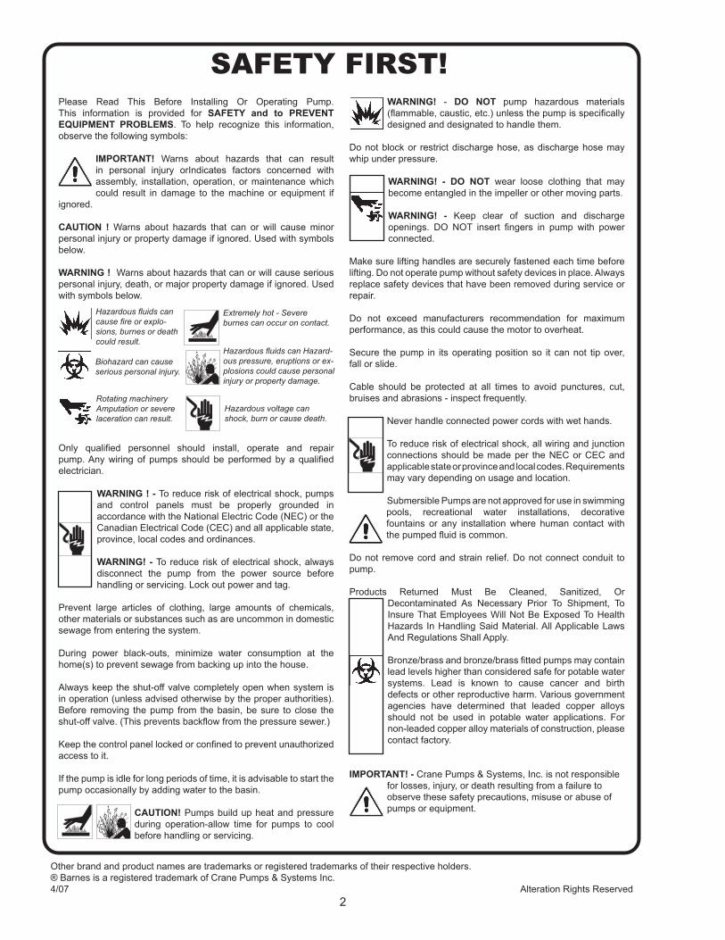
Please Read This Before Installing Or Operating Pump. This information is provided for SAFETY and to PREVENT EQUIPMENT PROBLEMS. To help recognize this information, observe the following symbols:
IMPORTANT! Warns about hazards that can result in personal injury orIndicates factors concerned with assembly, installation, operation, or maintenance which could result in damage to the machine or equipment if
ignored.
CAUTION ! Warns about hazards that can or will cause minor personal injury or property damage if ignored. Used with symbols below.
WARNING ! Warns about hazards that can or will cause serious personal injury, death, or major property damage if ignored. Used with symbols below.
Only qualified personnel should install, operate and repair pump. Any wiring of pumps should be performed by a qualified electrician.
WARNING ! - To reduce risk of electrical shock, pumps and control panels must be properly grounded in accordance with the National Electric Code (NEC) or the Canadian Electrical Code (CEC) and all applicable state, province, local codes and ordinances.
WARNING! - To reduce risk of electrical shock, always disconnect the pump from the power source before handling or servicing. Lock out power and tag.
Prevent large articles of clothing, large amounts of chemicals, other materials or substances such as are uncommon in domestic sewage from entering the system.
During power black-outs, minimize water consumption at the home(s) to prevent sewage from backing up into the house.
Always keep the shut-off valve completely open when system is in operation (unless advised otherwise by the proper authorities). Before removing the pump from the basin, be sure to close the shut-off valve. (This prevents backflow from the pressure sewer.)
Keep the control panel locked or confined to prevent unauthorized access to it.
If the pump is idle for long periods of time, it is advisable to start the pump occasionally by adding water to the basin.
CAUTION! Pumps build up heat and pressure during operation-allow time for pumps to cool before handling or servicing.
WARNING! - DO NOT pump hazardous materials (flammable, caustic, etc.) unless the pump is specifically designed and designated to handle them.
Do not block or restrict discharge hose, as discharge hose may whip under pressure.
WARNING! - DO NOT wear loose clothing that may become entangled in the impeller or other moving parts.
WARNING! - Keep clear of suction and discharge openings. DO NOT insert fingers in pump with power connected.
Make sure lifting handles are securely fastened each time before lifting. Do not operate pump without safety devices in place. Always replace safety devices that have been removed during service or repair.
Do not exceed manufacturers recommendation for maximum performance, as this could cause the motor to overheat.
Secure the pump in its operating position so it can not tip over, fall or slide.
Cable should be protected at all times to avoid punctures, cut, bruises and abrasions - inspect frequently.
Never handle connected power cords with wet hands.
To reduce risk of electrical shock, all wiring and junction connections should be made per the NEC or CEC and applicable state or province and local codes. Requirements may vary depending on usage and location.
Submersible Pumps are not approved for use in swimming pools, recreational water installations, decorative fountains or any installation where human contact with the pumped fluid is common.
Do not remove cord and strain relief. Do not connect conduit to pump.
Products Returned Must Be Cleaned, Sanitized, Or Decontaminated As Necessary Prior To Shipment, To Insure That Employees Will Not Be Exposed To Health Hazards In Handling Said Material. All Applicable Laws And Regulations Shall Apply. Bronze/brass and bronze/brass fitted pumps may contain lead levels higher than considered safe for potable water systems. Lead is known to cause cancer and birth defects or other reproductive harm. Various government agencies have determined that leaded copper alloys should not be used in potable water applications. For non-leaded copper alloy materials of construction, please contact factory.
IMPORTANT! - Crane Pumps & Systems, Inc. is not responsible for losses, injury, or death resulting from a failure to observe these safety precautions, misuse or abuse of pumps or equipment.
SAFETY FIRST!
Hazardous fluids can cause fire or explo-sions, burnes or death could result.
Extremely hot - Severe burnes can occur on contact.
Biohazard can cause serious personal injury.
Hazardous fluids can Hazard-ous pressure, eruptions or ex-plosions could cause personal injury or property damage.
Rotating machineryAmputation or severe laceration can result.
Hazardous voltage can shock, burn or cause death.
Other brand and product names are trademarks or registered trademarks of their respective holders.® Barnes is a registered trademark of Crane Pumps & Systems Inc.4/07 Alteration Rights Reserved
3
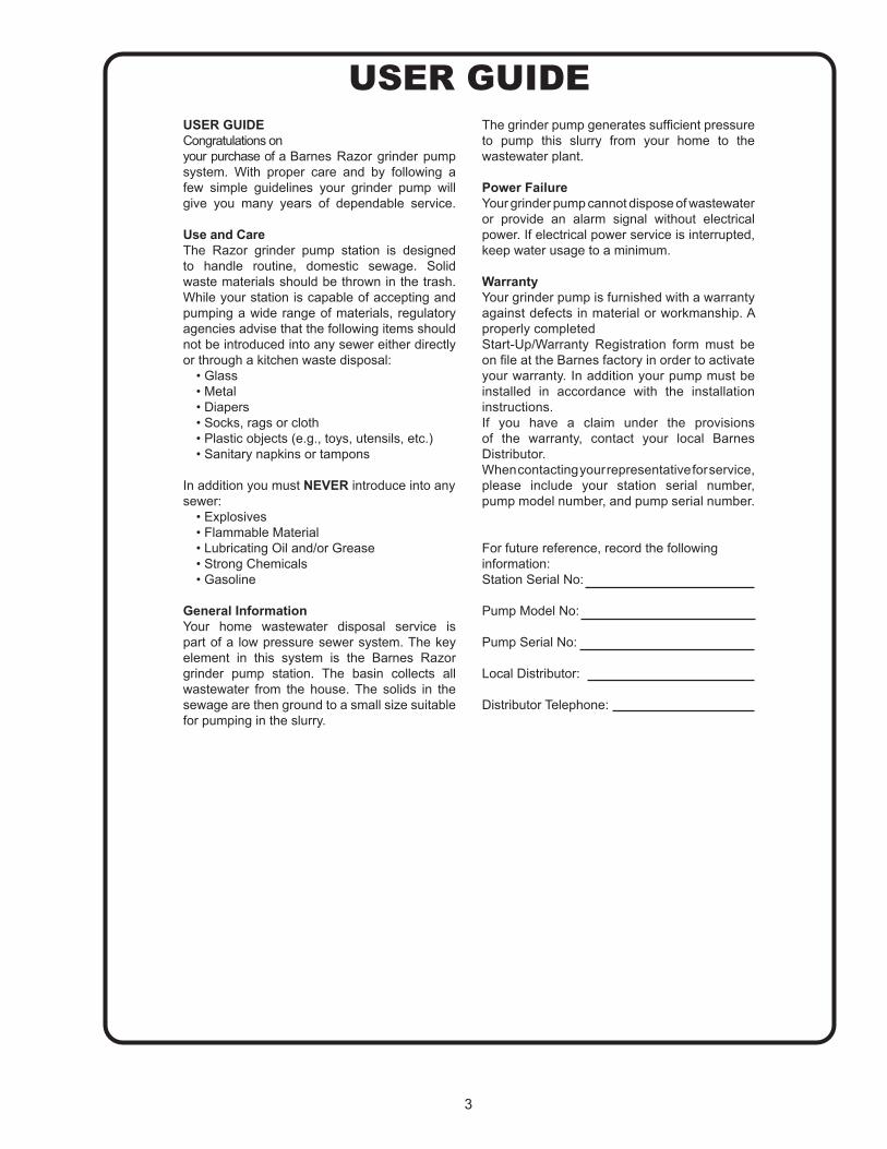
USER GUIDEUSER GUIDECongratulations on your purchase of a Barnes Razor grinder pump system. With proper care and by following a few simple guidelines your grinder pump will give you many years of dependable service.
Use and CareThe Razor grinder pump station is designed to handle routine, domestic sewage. Solid waste materials should be thrown in the trash. While your station is capable of accepting and pumping a wide range of materials, regulatory agencies advise that the following items should not be introduced into any sewer either directly or through a kitchen waste disposal:
• Glass• Metal• Diapers• Socks, rags or cloth• Plastic objects (e.g., toys, utensils, etc.)• Sanitary napkins or tampons
In addition you must NEVER introduce into any sewer:
• Explosives• Flammable Material• Lubricating Oil and/or Grease• Strong Chemicals• Gasoline
General InformationYour home wastewater disposal service is part of a low pressure sewer system. The key element in this system is the Barnes Razor grinder pump station. The basin collects all wastewater from the house. The solids in the sewage are then ground to a small size suitable for pumping in the slurry.
The grinder pump generates sufficient pressure to pump this slurry from your home to the wastewater plant.
Power FailureYour grinder pump cannot dispose of wastewater or provide an alarm signal without electrical power. If electrical power service is interrupted, keep water usage to a minimum.
WarrantyYour grinder pump is furnished with a warranty against defects in material or workmanship. A properly completed Start-Up/Warranty Registration form must be on file at the Barnes factory in order to activate your warranty. In addition your pump must be installed in accordance with the installation instructions.If you have a claim under the provisions of the warranty, contact your local Barnes Distributor.When contacting your representative for service, please include your station serial number, pump model number, and pump serial number.
For future reference, record the following information:Station Serial No:
Pump Model No:
Pump Serial No:
Local Distributor:
Distributor Telephone:
4
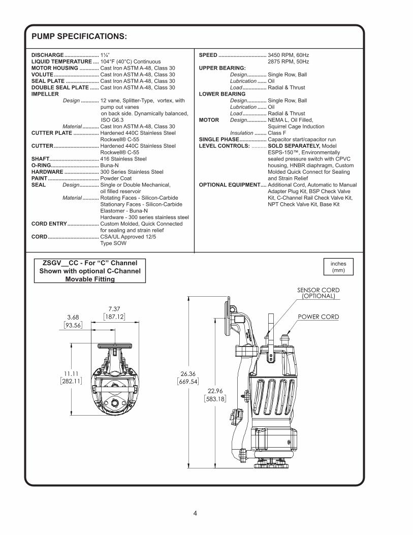
PUMP SPECIFICATIONS:
inches(mm)
DISCHARGE ....................... 1¼”LIQUID TEMPERATURE .... 104°F (40°C) ContinuousMOTOR HOUSING ............. Cast Iron ASTM A-48, Class 30VOLUTE .............................. Cast Iron ASTM A-48, Class 30SEAL PLATE ...................... Cast Iron ASTM A-48, Class 30 DOUBLE SEAL PLATE ...... Cast Iron ASTM A-48, Class 30IMPELLER Design ............ 12 vane, Splitter-Type, vortex, with pump out vanes on back side. Dynamically balanced, ISO G6.3 Material ........... Cast Iron ASTM A-48, Class 30CUTTER PLATE ................. Hardened 440C Stainless Steel Rockwell® C-55CUTTER .............................. Hardened 440C Stainless Steel Rockwell® C-55SHAFT ................................. 416 Stainless SteelO-RING ................................ Buna-NHARDWARE ....................... 300 Series Stainless SteelPAINT .................................. Powder CoatSEAL Design ............. Single or Double Mechanical,
oil filled reservoir Material ........... Rotating Faces - Silicon-Carbide Stationary Faces - Silicon-Carbide Elastomer - Buna-N Hardware - 300 series stainless steelCORD ENTRY ..................... Custom Molded, Quick Connected for sealing and strain reliefCORD .................................. CSA/UL Approved 12/5 Type SOW
SPEED ................................ 3450 RPM, 60Hz 2875 RPM, 50Hz
UPPER BEARING: Design ............. Single Row, Ball Lubrication ...... Oil Load ................ Radial & ThrustLOWER BEARING Design ............. Single Row, Ball Lubrication ...... Oil Load ................ Radial & ThrustMOTOR Design ............. NEMA L, Oil Filled, Squirrel Cage Induction Insulation ........ Class FSINGLE PHASE .................. Capacitor start/capacitor runLEVEL CONTROLS: .......... SOLD SEPARATELY, Model ESPS-150™, Environmentally sealed pressure switch with CPVC housing, HNBR diaphragm, Custom Molded Quick Connect for Sealing and Strain ReliefOPTIONAL EQUIPMENT .... Additional Cord, Automatic to Manual Adapter Plug Kit, BSP Check Valve Kit, C-Channel Rail Check Valve Kit, NPT Check Valve Kit, Base Kit
ZSGV__CC - For “C” ChannelShown with optional C-Channel
Movable Fitting
187.12
7.37
282.1111.11
93.563.68
669.5426.36
583.1822.96
POWER CORD
SENSOR CORD(OPTIONAL)
BURKS PUMPS · BARNES · SELLERSPROSSER · WEINMAN · DEMING
D
C
B
AA
B
C
D
12345678
8 7 6 5 4 3 2 1
AND WILL NOT BE USED TO MANUFACTURE OR PROCURE THE MANUFACTURE OF
CAGE NO THIS DRAWING IS APPROVED FOR UNCONTROLLED DISTRIBUTION
RESERVES THE RIGHT TO CHANGE PRODUCT WITHOUT PRIOR WRITTEN NOTIFICATION
DWG NO
TITLE
REV
SHEETWWW.CRANEPUMPS.COM 1 OF 1DRAWING NUMBER
TITLE 96046
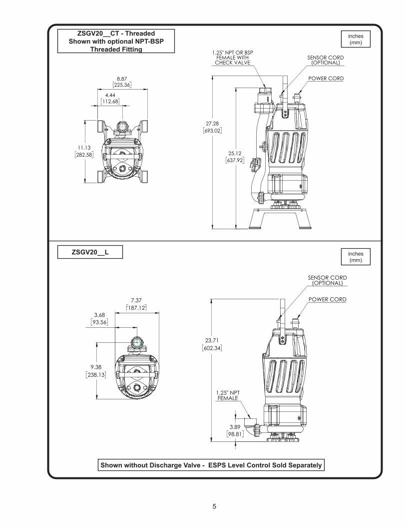
5
inches(mm)
Shown without Discharge Valve - ESPS Level Control Sold Separately
ZSGV20__CT - ThreadedShown with optional NPT-BSP
Threaded Fitting
ZSGV20__L inches(mm)
225.368.87
282.5811.13
112.684.44
637.9225.12
693.0227.28
POWER CORD
SENSOR CORD(OPTIONAL)
1.25" NPT OR BSPFEMALE WITH
CHECK VALVE
BURKS PUMPS · BARNES · SELLERSPROSSER · WEINMAN · DEMING
D
C
B
AA
B
C
D
12345678
8 7 6 5 4 3 2 1
AND WILL NOT BE USED TO MANUFACTURE OR PROCURE THE MANUFACTURE OF
CAGE NO THIS DRAWING IS APPROVED FOR UNCONTROLLED DISTRIBUTION
RESERVES THE RIGHT TO CHANGE PRODUCT WITHOUT PRIOR WRITTEN NOTIFICATION
DWG NO
TITLE
REV
SHEETWWW.CRANEPUMPS.COM 1 OF 1DRAWING NUMBER
TITLE 96046
187.127.37
238.139.38
93.563.68
602.3423.71
POWER CORD
SENSOR CORD(OPTIONAL)
1.25" NPTFEMALE
BURKS PUMPS · BARNES · SELLERSPROSSER · WEINMAN · DEMING
D
C
B
AA
B
C
D
12345678
8 7 6 5 4 3 2 1
AND WILL NOT BE USED TO MANUFACTURE OR PROCURE THE MANUFACTURE OF
CAGE NO THIS DRAWING IS APPROVED FOR UNCONTROLLED DISTRIBUTION
RESERVES THE RIGHT TO CHANGE PRODUCT WITHOUT PRIOR WRITTEN NOTIFICATION
DWG NO
TITLE
REV
SHEETWWW.CRANEPUMPS.COM 1 OF 1DRAWING NUMBER
TITLE 96046
98.813.89
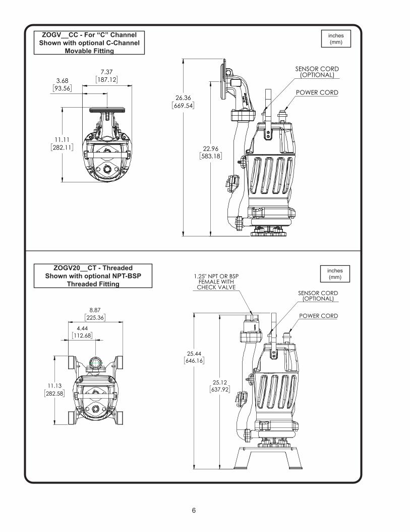
6
inches(mm)
inches(mm)
ZOGV__CC - For “C” ChannelShown with optional C-Channel
Movable Fitting
ZOGV20__CT - ThreadedShown with optional NPT-BSP
Threaded Fitting
225.368.87
282.5811.13
112.684.44
637.9225.12
646.1625.44
POWER CORD
SENSOR CORD(OPTIONAL)
1.25" NPT OR BSPFEMALE WITH
CHECK VALVE
BURKS PUMPS · BARNES · SELLERSPROSSER · WEINMAN · DEMING
D
C
B
AA
B
C
D
12345678
8 7 6 5 4 3 2 1
AND WILL NOT BE USED TO MANUFACTURE OR PROCURE THE MANUFACTURE OF
CAGE NO THIS DRAWING IS APPROVED FOR UNCONTROLLED DISTRIBUTION
RESERVES THE RIGHT TO CHANGE PRODUCT WITHOUT PRIOR WRITTEN NOTIFICATION
DWG NO
TITLE
REV
SHEETWWW.CRANEPUMPS.COM 1 OF 1DRAWING NUMBER
TITLE 96046
187.127.37
282.1111.11
93.563.68
669.5426.36
583.1822.96
POWER CORD
SENSOR CORD(OPTIONAL)
BURKS PUMPS · BARNES · SELLERSPROSSER · WEINMAN · DEMING
D
C
B
AA
B
C
D
12345678
8 7 6 5 4 3 2 1
AND WILL NOT BE USED TO MANUFACTURE OR PROCURE THE MANUFACTURE OF
CAGE NO THIS DRAWING IS APPROVED FOR UNCONTROLLED DISTRIBUTION
RESERVES THE RIGHT TO CHANGE PRODUCT WITHOUT PRIOR WRITTEN NOTIFICATION
DWG NO
TITLE
REV
SHEETWWW.CRANEPUMPS.COM 1 OF 1DRAWING NUMBER
TITLE 96046
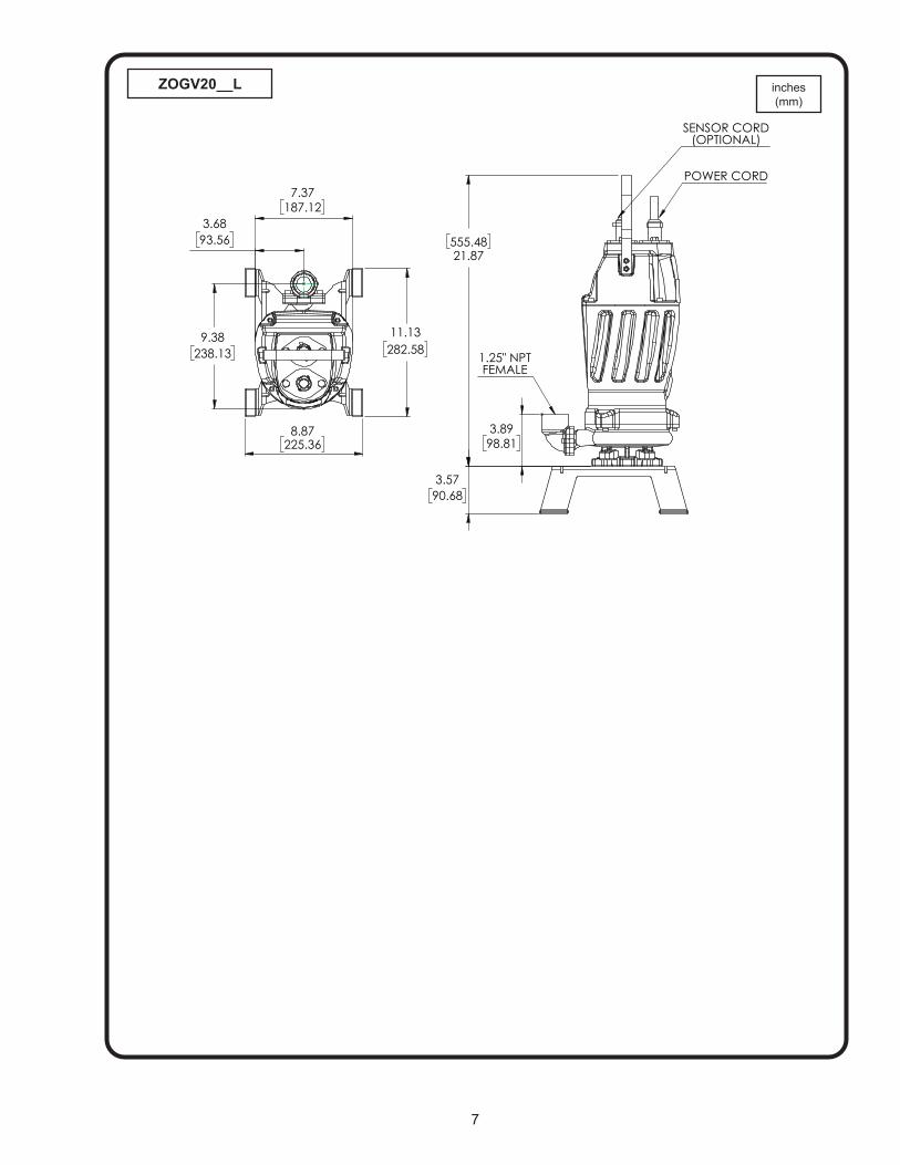
7
ZOGV20__L inches(mm)
187.12
7.37
225.36
8.87
282.5811.13
238.13
9.38
93.563.68
555.4821.87
90.683.57
98.813.89
POWER CORD
SENSOR CORD(OPTIONAL)
1.25" NPTFEMALE
BURKS PUMPS · BARNES · SELLERSPROSSER · WEINMAN · DEMING
D
C
B
AA
B
C
D
12345678
8 7 6 5 4 3 2 1
AND WILL NOT BE USED TO MANUFACTURE OR PROCURE THE MANUFACTURE OF
CAGE NO THIS DRAWING IS APPROVED FOR UNCONTROLLED DISTRIBUTION
RESERVES THE RIGHT TO CHANGE PRODUCT WITHOUT PRIOR WRITTEN NOTIFICATION
DWG NO
TITLE
REV
SHEETWWW.CRANEPUMPS.COM 1 OF 1DRAWING NUMBER
TITLE 96046
8
BURKS PUMPS · BARNES · SELLERSPROSSER · WEINMAN · DEMING
D
C
B
AA
B
C
D
12345678
8 7 6 5 4 3 2 1
AND WILL NOT BE USED TO MANUFACTURE OR PROCURE THE MANUFACTURE OF
CAGE NO THIS DRAWING IS APPROVED FOR UNCONTROLLED DISTRIBUTION
RESERVES THE RIGHT TO CHANGE PRODUCT WITHOUT PRIOR WRITTEN NOTIFICATION
DWG NO
TITLE
REV
SHEETWWW.CRANEPUMPS.COM 1 OF 1DRAWING NUMBER
TITLE 96046
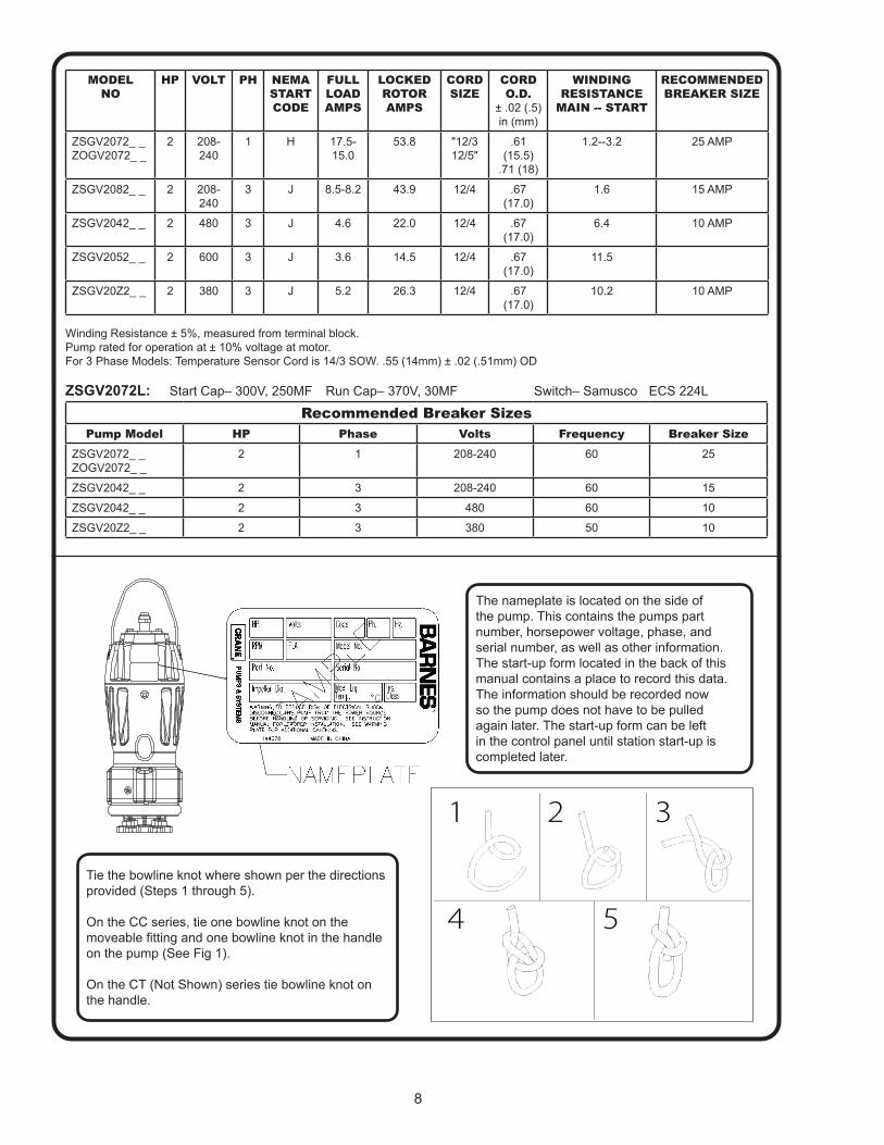
MODELNO
HP VOLT PH NEMASTARTCODE
FULLLOADAMPS
LOCKEDROTORAMPS
CORDSIZE
CORDO.D.
± .02 (.5)in (mm)
WINDINGRESISTANCE
MAIN -- START
RECOMMENDED BREAKER SIZE
ZSGV2072_ _ ZOGV2072_ _
2 208-240
1 H 17.5-15.0
53.8 "12/3 12/5"
.61 (15.5)
.71 (18)
1.2--3.2 25 AMP
ZSGV2082_ _ 2 208-240
3 J 8.5-8.2 43.9 12/4 .67 (17.0)
1.6 15 AMP
ZSGV2042_ _ 2 480 3 J 4.6 22.0 12/4 .67 (17.0)
6.4 10 AMP
ZSGV2052_ _ 2 600 3 J 3.6 14.5 12/4 .67 (17.0)
11.5
ZSGV20Z2_ _ 2 380 3 J 5.2 26.3 12/4 .67 (17.0)
10.2 10 AMP
Winding Resistance ± 5%, measured from terminal block.Pump rated for operation at ± 10% voltage at motor.For 3 Phase Models: Temperature Sensor Cord is 14/3 SOW. .55 (14mm) ± .02 (.51mm) OD
ZSGV2072L: Start Cap– 300V, 250MF Run Cap– 370V, 30MF Switch– Samusco ECS 224L
Recommended Breaker SizesPump Model HP Phase Volts Frequency Breaker Size
ZSGV2072_ _ ZOGV2072_ _
2 1 208-240 60 25
ZSGV2042_ _ 2 3 208-240 60 15
ZSGV2042_ _ 2 3 480 60 10
ZSGV20Z2_ _ 2 3 380 50 10
The nameplate is located on the side of the pump. This contains the pumps part number, horsepower voltage, phase, and serial number, as well as other information. The start-up form located in the back of this manual contains a place to record this data. The information should be recorded now so the pump does not have to be pulled again later. The start-up form can be left in the control panel until station start-up is completed later.
� � �
� �
Tie the bowline knot where shown per the directions provided (Steps 1 through 5).
On the CC series, tie one bowline knot on the moveable fitting and one bowline knot in the handle on the pump (See Fig 1).
On the CT (Not Shown) series tie bowline knot on the handle.
9
RECEIVING/UNPACKING:Upon receiving the pump, it should be inspected for dam-age or shortages. If damage has occurred, file a claim immediately with the company that delivered the pump. Unpack pump and record pump serial and model number before installing. If the manual is removed from the pack-aging, do not lose or misplace.
STORAGE:Short Term- For best results, pumps can be retained in storage, as factory assembled, in a dry atmosphere with constant temperatures for up to six (6) months.
Long Term- Any length of time exceeding six (6) months, but not more than twenty-four (24) months. The units should be stored in a temperature controlled area, a roofed over walled enclosure that provides protection from the elements (rain, snow, wind-blown dust, etc.), and whose temperature can be maintained between +40 deg. F and +120 deg. F. If extended high humidity is expected to be a problem, all exposed parts should be inspected before storage and all surfaces that have the paint scratched, damaged, or worn should be recoated with a air dry enamel paint. All surfaces should then be sprayed with a rust-inhibiting oil.
Pump should be stored in its original shipping container. On initial start up, rotate impeller by hand to assure seal and impeller rotate freely. If it is required that the pump be installed and tested before the long term storage begins, such installation will be allowed provided:
1.) The pump is not installed under water for more than one (1) month.2.) Immediately upon satisfactory completion of the test, the pump is removed, thoroughly dried, repacked in the original shipping container, and placed in a temperature controlled storage area.3.) Before placing pump into service, pump should be brought to operational temperature range. Excessive or direct heating or cooling should NOT be used.
OPERATION TEMPERATURE RANGE: +35ºF (2ºC) to 104ºF (40ºC). SERVICE CENTERS: For the location of the nearest Barnes Service Center, check your Barnes representative or Crane Pumps & Systems, Inc.Service Department in Piqua, Ohio, telephone(937) 778-8947 or in Brampton, Ontario, Canada (905) 457-6223.
INSTALLATION: Location - The pump is designed to fit into your basin ei-ther by sliding down the rail assembly, or by being mount-ed on a pump base. THIS PUMP MUST BE INSTALLED WITH A MINIMUM OF 3 INCHES AND A MAXIMUM OF 4.5 INCHES OF CLEARANCE UNDER THE PUMP FOR THE ENTRANCE OF SEWAGE SOLIDS.
Discharge - Assemble discharge piping or hose assembly (whichever is required by your application), to the pump. Discharge piping should be as short as possible. Both a check valve and a shut-off valve are required for each pump being used. The check valve is used to prevent backflow into the sump. Excessive backflow can cause flooding and/or damage to the pump. The shut-off valve is used to stop system flow during pump or check valve servicing. An anti-siphon valve is also required.
Package Systems- Refer to manual supplied with basin package system.
ELECTRICAL CONNECTIONS:
Pump Cables - The cord assembly mounted to the pump must NOT be modified in any way except for shortening to a specific application. Any splice between the pump and the control panel must be made in accordance with the National Electric Code or the Canadian Electric Code and all applicable state, province and local electric codes. It is recommended that a junction box, be mounted outside the sump or be of at least Nema 4 (EEMAC-4) construction if located within the wet well. DO NOT USE THE POWER OR CONTROL CABLES TO LIFT PUMP!
Overload Protection - For single phase, the type of in-winding overload protector used is referred to as an inherent overheating protector and operates on the combined effect of temperature and current. This means that the overload protector will trip out and shut the pump off if the windings become too hot, or the load current becomes too high. It will then automatically reset and start the pump after the motor cools to a safe temperature. In the event of an overload, the source of this condition should be determined and rectified immediately. DO NOT LET THE PUMP CYCLE OR RUN IF AN OVERLOAD CONDITION OCCURS !
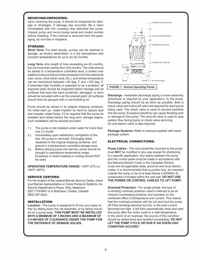
FIGURE 1 - Normal Operating Points
3.57
BOTTOM OF BASIN
STANDARD OFF POSITION
STANDARD ON POSITION
LAG ON POSITION (DUPLEX)
STANDARD ALARM POSITION
8.16
8.00
4.00
6.00
REVISIONS
REV. ECO # DESCRIPTION DR CKD DATE APP
A XXXX-XX RELEASE XXX XXX MM/DD/YYYY XXX
D
C
B
AA
B
C
D
12345678
8 7 6 5 4 3 2 1
E
F
E
F
INSIDE RADII = .015"-.040"BREAK ALL MACHINED CORNERS .005"-.015"FINISHED DIAMETERS CONCENTRIC WITHIN .002FINISHED FACES PARALLEL WITHIN .002
1:4D
DESCRIPTION 1DESCRIPTION 2
This print is and contains con�dential proprietary information owned exclusively by CRANE PUMPS & SYSTEMS INC., and it is furnished on a strictly con�dential basis. This restriction includes, but is not limited to the condition that this print will only be used as a record or to identify or inspect parts or for other information purposes, and will not be used to manufacture or procure the manufacture of the parts shown in this print by any source other than CRANE PUMPS & SYSTEMS INC..
CASTING
MATL
1 OF 1
PART NUMBER
SHEETCAGE NO 96046
DWG NO
SCALE
SIZE
MATERIAL
MATERIAL PART #
DIMENSIONS ARE IN INCHESTOLERANCES FOR MACH DIM:2 PL DECIMALS ±.0153 PL DECIMALS ±.005ANGLES ±1/2°SURFACE FINISH OF 125
UNLESS OTHERWISESPECIFIED
*CHARACTERISTICKEY
10
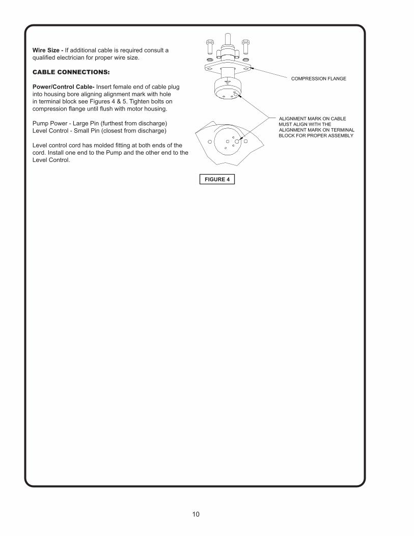
FIGURE 4
Wire Size - If additional cable is required consult a qualified electrician for proper wire size.
CABLE CONNECTIONS:
Power/Control Cable- Insert female end of cable plug into housing bore aligning alignment mark with hole in terminal block see Figures 4 & 5. Tighten bolts on compression flange until flush with motor housing.
Pump Power - Large Pin (furthest from discharge)Level Control - Small Pin (closest from discharge)
Level control cord has molded fitting at both ends of the cord. Install one end to the Pump and the other end to the Level Control.
11
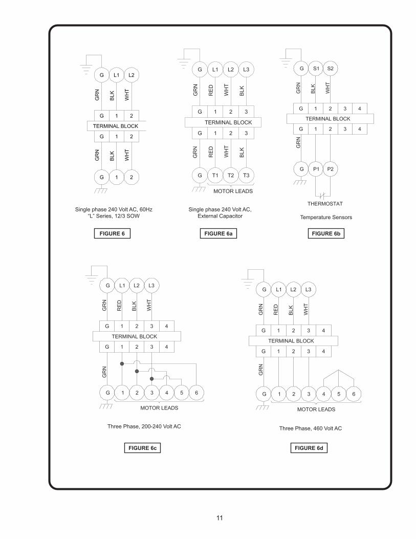
FIGURE 6
Single phase 240 Volt AC, 60Hz“L” Series, 12/3 SOW
FIGURE 6b
Temperature Sensors
FIGURE 6c
Three Phase, 200-240 Volt AC
FIGURE 6d
Three Phase, 460 Volt AC
FIGURE 6a
Single phase 240 Volt AC, External Capacitor
12
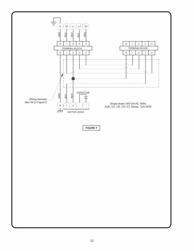
Single phase 240 Volt AC, 60HzAUE, CC, CE, CO, CT, Series, 12/5 SOW
FIGURE 7
Wiring HarnessItem 54 on Figure 8

13
TROUBLE SHOOTINGCAUTION ! Always disconnect the pump from the electrical power source before handling.If the system fails to operate properly, carefully read instructions and perform maintenance recommendations.If operating problems persist, the following chart may be of assistance in identifying and correcting them:MATCH “CAUSE” NUMBER WITH CORRELATING “CORRECTION” NUMBER.
NOTE: Not all problems and corrections will apply to each pump model.PROBLEM CAUSE CORRECTION
Pump will not run 1. Poor electrical connection, blown fuse, tripped breaker or other interruption of power, improper power supply.2. Motor or switch inoperative (to isolate cause, go to manual operation of pump).2a. Float movement restricted.2b. Switch will not activate pump or is defec-tive.3a. Insufficient liquid level.3b. Switch is unable to activate
1. Check all electrical connections for security. Have electrician measure current in motor leads, if current is within ±20% of locked rotor Amps, impeller is probably locked. If current is 0, overload may be tripped. Remove power, allow pump to cool, then recheck current.2a. Reposition pump or clean basin as required to provide adequate clearance for float.2b. Disconnect level control. Set ohmmeter for a low range, such as 100 ohms full scale and connect to level control leads. Actuate level control manually and check to see that ohmmeter shows zero ohms for closed switch and full scale for open switch. (Float Switch).3a. Make sure liquid level is at least equal to suggested turn-on point.3b. Rotate ESPS level control in horizontal position.4. Recheck all sizing calculations to determine proper pump size.5. Check discharge line for restrictions, including ice if line passes through or into cold areas.6. Remove and examine check valve for proper installation and freedom of operation.7. Open valve.8. Check cutter for freedom of operation, security and condition. Clean cutter and inlet of any obstruction.9. Loosen union slightly to allow trapped air to escape.Verify that turn-off level of switch is set so that the suction is always flooded. Clean vent hole.10. Remove & examine for damage. Replace pump stator if required.11. Repair fixtures as required to eliminate leakage.12. Check pump temperature limits & fluid temperature.13. Replace portion of discharge pipe with flexible connector.14. Turn to automatic position.15. Check for leaks around basin inlet and outlets.
Pump will not turn off 2a. Float movement restricted.2b. Switch will not activate pump or is defec-tive.4. Excessive inflow or pump not properly sized for application.9. Pump may be airlocked.14. H-O-A switch on panel is in “HAND” posi-tion
Pump hums but does not run 1. Incorrect voltage8. Cutter jammed or loose on shaft, worn or damaged, inlet plugged.
Pump delivers insufficient capacity 1. Incorrect voltage.4. Excessive inflow or pump not properly sized for application.5. Discharge restricted.6. Check valve stuck closed or installed backwards.7. Shut-off valve closed.8. Cutter jammed or loose on shaft, worn or damaged, inlet plugged.9. Pump may be airlocked.10. Pump stator damaged/torn.
Pump cycles too frequently or runs periodically when fixtures are not in use
6. Check valve stuck closed or installed backwards.11. Fixtures are leaking.15. Ground water entering basin.
Pump shuts off and turns on indepen-dent of switch, (trips thermal overload protector). CAUTION! Pump may start unexpectedly. Disconnect power supply.
1. Incorrect voltage.4. Excessive inflow or pump not properly sized for application.8. Cutter jammed, loose on shaft, worn or damaged, inlet plugged.12. Excessive water temperature.
Pump operates noisily or vibrates excessively
4. Operating at too high a pressure.5. Discharge restricted.8. Cutter broken.13. Piping attachments to buiding structure too rigid or too loose.
14
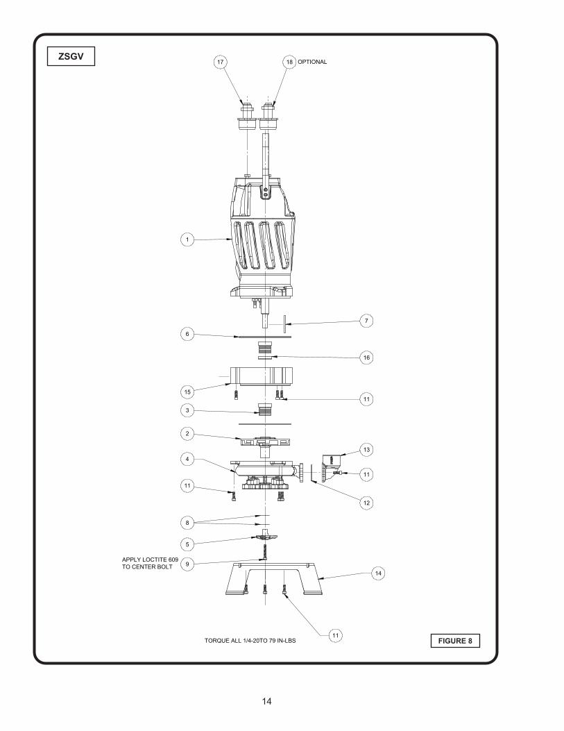
FIGURE 8
ZSGV
1
17 18
7
16
13
12
11
9
5
8
2
3
15
6
OPTIONAL
11
11
14
4
11
Contact your local distributer or the factory for other impeller sizes, cord leanths and other optional equipment
APPLY LOCTITE 609TO CENTER BOLT
TORQUE ALL 1/4-20TO 79 IN-LBS
REVISIONS
REV. ECO # DESCRIPTION DR CKD DATE APP
A XXXX-XX RELEASE XXX XXX MM/DD/YYYY XXX
ITEM NO. QTY. PART NUMBER DESCRIPTION MATERIAL
NOT SHOWN 1 145400 CAP,START,300V,250MFNOT SHOWN 1 145401 CAP,RUN,370V,30MFNOT SHOWN 1 139741 SWITCH,START,MOTOR
18 1 SEE BOM SENSOR CORD (OPTIONAL)17 1 SEE BOM POWER CORD16 1 142924 COLLAR,SHAFT,.875" Plain Carbon Steel15 1 141644 PLATE,SEAL,DOUBLE Gray Cast Iron14 1 145549 ASSY,BASE,SS,FEET13 1 141650 ADAPTER,VERT,1.25NPT CLASS 30 CI12 1 2-31003-222 O-RING,-222,BUNA,1.484ID BUNA-N11 12 11-30-1 SCREW,SKHD,1/4-20,.75" 18-8 SS10 A/R 030237 LOCTITE #609 THREAD LOCK9 1 11-34-1 SCREW,SKHD,1/4-20,1.50" 300 SS
8 A/R143567-005143567-010143567-030143567-060
SHIM,XXX,.69ID,1.03OD 316 SS
7 1 141704 KEY,3/16SQ,2.00LG,18-8SS 18-86 2 2-31003-162 O-RING,-162,BUNA,5.737ID BUNA-N5 1 141653 CUTTER,NGG 440 SS4 1 145611 ASSY,VOLUTE,SGV/OGV3 2 111131SD SEAL,MECH,.875",SC/SC/B SC/SC/B2 1 141655BTA1 IMPELLER,VORTEX,OGV,SGV CLASS 30 CI
1 1
143448 ASSY,DRIVER,RAZOR(MANUAL) 2HP,60HZ,208-240V,1PH
145241 ASSY,DRIVER,RAZOR,MS&TS(AUTO) 2HP,60HZ,208-240V,1PH
145242 ASSY,DRIVER,RAZOR,MS&TS(AUTO) 2HP,60HZ,208-240V,3PH
145243 ASSY,DRIVER,RAZOR,MS&TS(AUTO) 2HP,60HZ,460V,3PH
145244 ASSY,DRIVER,RAZOR,MS&TS(AUTO) 2HP,60HZ,575V,3PH
145247 ASSY,DRIVER,RAZOR,TS(AUTO) 2HP,60HZ,208-240V,3PH
145248 ASSY,DRIVER,RAZOR,TS(AUTO) 2HP,60HZ,460V,3PH
145249 ASSY,DRIVER,RAZOR,TS(AUTO) 2HP,60HZ,575V,3PH
D
C
B
AA
B
C
D
12345678
8 7 6 5 4 3 2 1
E
F
E
F
INSIDE RADII = .015"-.040"BREAK ALL MACHINED CORNERS .005"-.015"FINISHED DIAMETERS CONCENTRIC WITHIN .002FINISHED FACES PARALLEL WITHIN .002
1:8D
DESCRIPTION 1DESCRIPTION 2
This print is and contains confidential proprietary information owned exclusively by CRANE PUMPS & SYSTEMS INC., and it is furnished on a strictly confidential basis. This restriction includes, but is not limited to the condition that this print will only be used as a record or to identify or inspect parts or for other information purposes, and will not be used to manufacture or procure the manufacture of the parts shown in this print by any source other than CRANE PUMPS & SYSTEMS INC..
CASTINGMATL
1 OF 1PART NUMBER
SHEETCAGE NO 96046
DWG NO
SCALE
SIZE
MATERIAL
MATERIAL PART #DIMENSIONS ARE IN INCHESTOLERANCES FOR MACH DIM:2 PL DECIMALS ±.0153 PL DECIMALS ±.005ANGLES ±1/2°SURFACE FINISH OF 125
UNLESS OTHERWISESPECIFIED
*CHARACTERISTICKEY
15
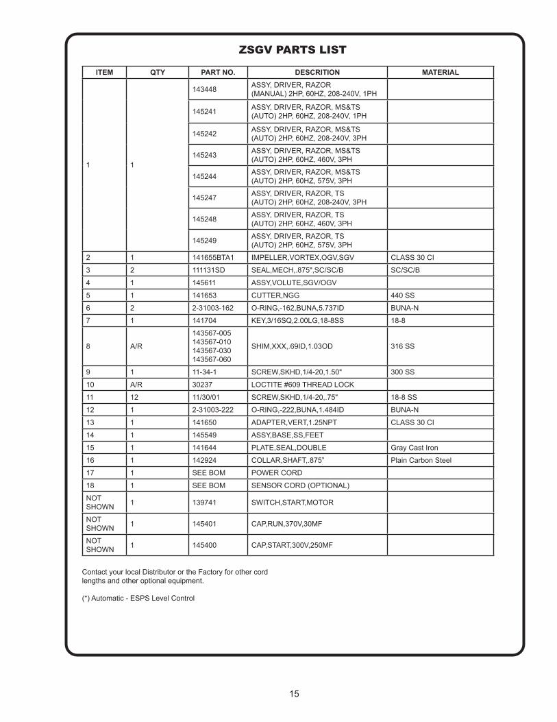
ZSGV PARTS LIST
ITEM QTY PART NO. DESCRITION MATERIAL
1 1
143448 ASSY, DRIVER, RAZOR (MANUAL) 2HP, 60HZ, 208-240V, 1PH
145241 ASSY, DRIVER, RAZOR, MS&TS (AUTO) 2HP, 60HZ, 208-240V, 1PH
145242 ASSY, DRIVER, RAZOR, MS&TS (AUTO) 2HP, 60HZ, 208-240V, 3PH
145243 ASSY, DRIVER, RAZOR, MS&TS (AUTO) 2HP, 60HZ, 460V, 3PH
145244 ASSY, DRIVER, RAZOR, MS&TS (AUTO) 2HP, 60HZ, 575V, 3PH
145247 ASSY, DRIVER, RAZOR, TS (AUTO) 2HP, 60HZ, 208-240V, 3PH
145248 ASSY, DRIVER, RAZOR, TS (AUTO) 2HP, 60HZ, 460V, 3PH
145249 ASSY, DRIVER, RAZOR, TS (AUTO) 2HP, 60HZ, 575V, 3PH
2 1 141655BTA1 IMPELLER,VORTEX,OGV,SGV CLASS 30 CI
3 2 111131SD SEAL,MECH,.875",SC/SC/B SC/SC/B
4 1 145611 ASSY,VOLUTE,SGV/OGV
5 1 141653 CUTTER,NGG 440 SS
6 2 2-31003-162 O-RING,-162,BUNA,5.737ID BUNA-N
7 1 141704 KEY,3/16SQ,2.00LG,18-8SS 18-8
8 A/R
143567-005 143567-010 143567-030 143567-060
SHIM,XXX,.69ID,1.03OD 316 SS
9 1 11-34-1 SCREW,SKHD,1/4-20,1.50" 300 SS
10 A/R 30237 LOCTITE #609 THREAD LOCK
11 12 11/30/01 SCREW,SKHD,1/4-20,.75" 18-8 SS
12 1 2-31003-222 O-RING,-222,BUNA,1.484ID BUNA-N
13 1 141650 ADAPTER,VERT,1.25NPT CLASS 30 CI
14 1 145549 ASSY,BASE,SS,FEET
15 1 141644 PLATE,SEAL,DOUBLE Gray Cast Iron
16 1 142924 COLLAR,SHAFT,.875” Plain Carbon Steel
17 1 SEE BOM POWER CORD
18 1 SEE BOM SENSOR CORD (OPTIONAL)
NOT SHOWN 1 139741 SWITCH,START,MOTOR
NOT SHOWN 1 145401 CAP,RUN,370V,30MF
NOT SHOWN 1 145400 CAP,START,300V,250MF
Contact your local Distributor or the Factory for other cord lengths and other optional equipment.
(*) Automatic - ESPS Level Control

16
FIGURE 8
ZOGV
12
15
116
9
12
4 12
14
13
2
3
1
1716
8
7
5
TORQUE ALL 1/4-20 TO 79 IN-LBS
APPLY LOCTITE 609TO CENTER BOLT
CONTACT YOUR LOCAL DISTRIBUTOR OR THE FACTORY FOR OTHER CORD LENGTHS AND OTHER OPTIONAL EQUIPMENT.
REVISIONS
REV. ECO # DESCRIPTION DR CKD DATE APP
A XXXX-XX RELEASE XXX XXX MM/DD/YYYY XXX
ITEM NO. QTY. PART NUMBER DESCRIPTION
1 1145253 ASSY,DRIVER,RAZOR
(AUTO) 2HP, 60 HZ, 208-230V, 1PH
145255 ASSY,DRIVER,RAZOR(MANUAL) 2HP, 60 HZ, 208-230V, 1PH
2 1 141655BTA1 IMPELLER,VORTEX,OGV,SGV3 1 111131SD SEAL,MECH,.875",SC/SC/B4 1 145611 ASSY,VOLUTE,SGV/OGV5 1 014270-SS PLUG,PIPE,.375-18NPT,C'SUNK6 1 141653 CUTTER,NGG7 1 2-31003-162 O-RING,-162,BUNA,5.737ID8 1 141704 KEY,3/16SQ,2.00LG,18-8SS
9 A/R143567-005143567-015143567-030143567-060
Shims
10 A/R 030237 LOCTITE #609 THREAD LOCK11 1 11-34-1 SCREW,SKHD,1/4-20,1.50"12 9 036803 SCREW,SKHD,1/4-20,.75"13 1 2-31003-222 O-RING,-222,BUNA,1.484ID14 1 141650 ADAPTER,VERT,1.25NPT15 1 145549 ASSY,BASE,SS,FEET16 1 SEE BOM POWER CORD…17 1 SEE BOM SENSOR CORD… (Optional)
NOT SHOWN 1 147000 CAP,START,300V,150MFNOT SHOWN 1 145402 CAP,RUN,370V,40MFNOT SHOWN 1 139741 SWITCH,START,MOTOR
D
C
B
AA
B
C
D
12345678
8 7 6 5 4 3 2 1
1:8B
DESCRIPTION 1DESCRIPTION 2
This print is and contains confidential proprietary information owned exclusively by CRANE PUMPS & SYSTEMS INC., and it is furnished on a strictly confidential basis. This restriction includes, but is not limited to the condition that this print will only be used as a record or to identify or inspect parts or for other information purposes, and will not be used to manufacture or procure the manufacture of the parts shown in this print by any source other than CRANE PUMPS & SYSTEMS INC..
MATL
1 OF 1PART NUMBER
SHEETCAGE NO 96046
DWG NO
SCALE
SIZE
MATERIALUNLESS OTHERWISE SPECIFIED: DIMENSIONSARE IN INCHES. TOLERANCES FOR CAST DIM:LESS THAN 7" - ±.067" & ABOVE - ±.10ANGLES ±1°
*CHARACTERISTICKEY
17
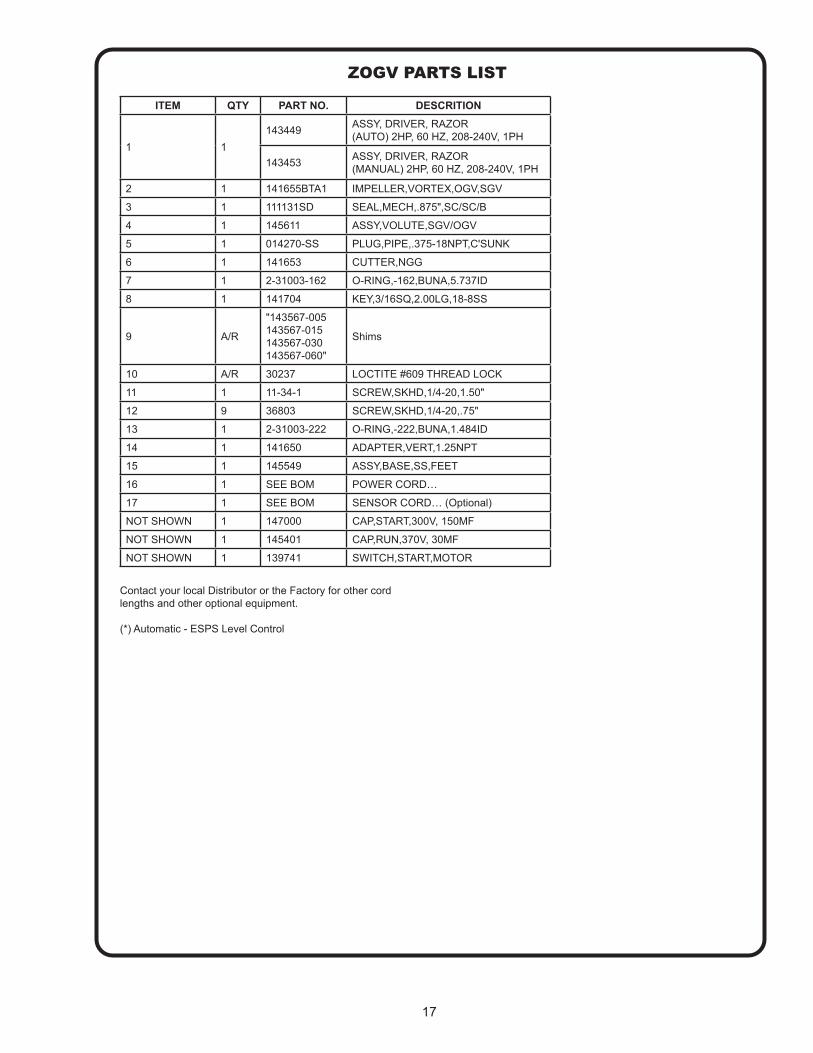
ZOGV PARTS LIST
ITEM QTY PART NO. DESCRITION
1 1143449 ASSY, DRIVER, RAZOR
(AUTO) 2HP, 60 HZ, 208-240V, 1PH
143453 ASSY, DRIVER, RAZOR (MANUAL) 2HP, 60 HZ, 208-240V, 1PH
2 1 141655BTA1 IMPELLER,VORTEX,OGV,SGV
3 1 111131SD SEAL,MECH,.875",SC/SC/B
4 1 145611 ASSY,VOLUTE,SGV/OGV
5 1 014270-SS PLUG,PIPE,.375-18NPT,C'SUNK
6 1 141653 CUTTER,NGG
7 1 2-31003-162 O-RING,-162,BUNA,5.737ID
8 1 141704 KEY,3/16SQ,2.00LG,18-8SS
9 A/R
"143567-005 143567-015 143567-030 143567-060"
Shims
10 A/R 30237 LOCTITE #609 THREAD LOCK
11 1 11-34-1 SCREW,SKHD,1/4-20,1.50"
12 9 36803 SCREW,SKHD,1/4-20,.75"
13 1 2-31003-222 O-RING,-222,BUNA,1.484ID
14 1 141650 ADAPTER,VERT,1.25NPT
15 1 145549 ASSY,BASE,SS,FEET
16 1 SEE BOM POWER CORD…
17 1 SEE BOM SENSOR CORD… (Optional)
NOT SHOWN 1 147000 CAP,START,300V, 150MF
NOT SHOWN 1 145401 CAP,RUN,370V, 30MF
NOT SHOWN 1 139741 SWITCH,START,MOTOR
Contact your local Distributor or the Factory for other cord lengths and other optional equipment.
(*) Automatic - ESPS Level Control
18
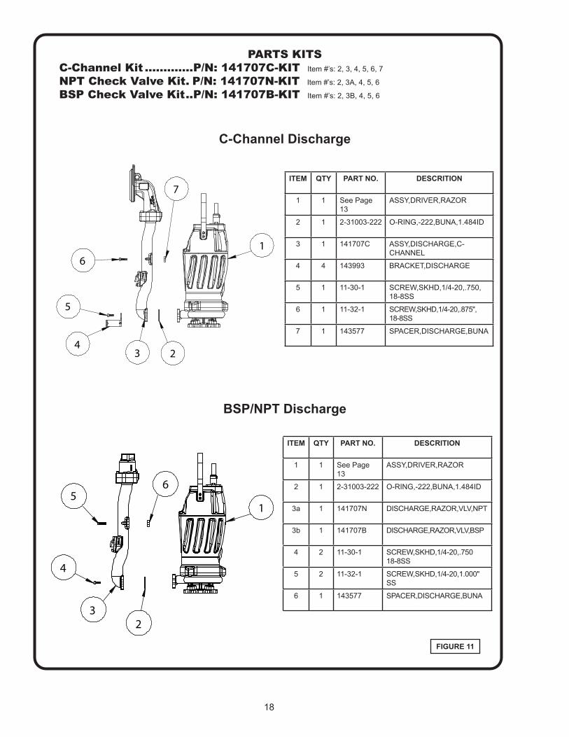
ITEM QTY PART NO. DESCRITION
1 1 See Page 13
ASSY,DRIVER,RAZOR
2 1 2-31003-222 O-RING,-222,BUNA,1.484ID
3a 1 141707N DISCHARGE,RAZOR,VLV,NPT
3b 1 141707B DISCHARGE,RAZOR,VLV,BSP
4 2 11-30-1 SCREW,SKHD,1/4-20,.750 18-8SS
5 2 11-32-1 SCREW,SKHD,1/4-20,1.000" SS
6 1 143577 SPACER,DISCHARGE,BUNA
FIGURE 11
ITEM QTY PART NO. DESCRITION
1 1 See Page 13
ASSY,DRIVER,RAZOR
2 1 2-31003-222 O-RING,-222,BUNA,1.484ID
3 1 141707C ASSY,DISCHARGE,C-CHANNEL
4 4 143993 BRACKET,DISCHARGE
5 1 11-30-1 SCREW,SKHD,1/4-20,.750, 18-8SS
6 1 11-32-1 SCREW,SKHD,1/4-20,.875", 18-8SS
7 1 143577 SPACER,DISCHARGE,BUNA
C-Channel Discharge
BSP/NPT Discharge
PARTS KITSC-Channel Kit .............P/N: 141707C-KIT Item #’s: 2, 3, 4, 5, 6, 7
NPT Check Valve Kit . P/N: 141707N-KIT Item #’s: 2, 3A, 4, 5, 6
BSP Check Valve Kit ..P/N: 141707B-KIT Item #’s: 2, 3B, 4, 5, 6
5
4
6
3
1
2
7
1
3
4
56
2
19
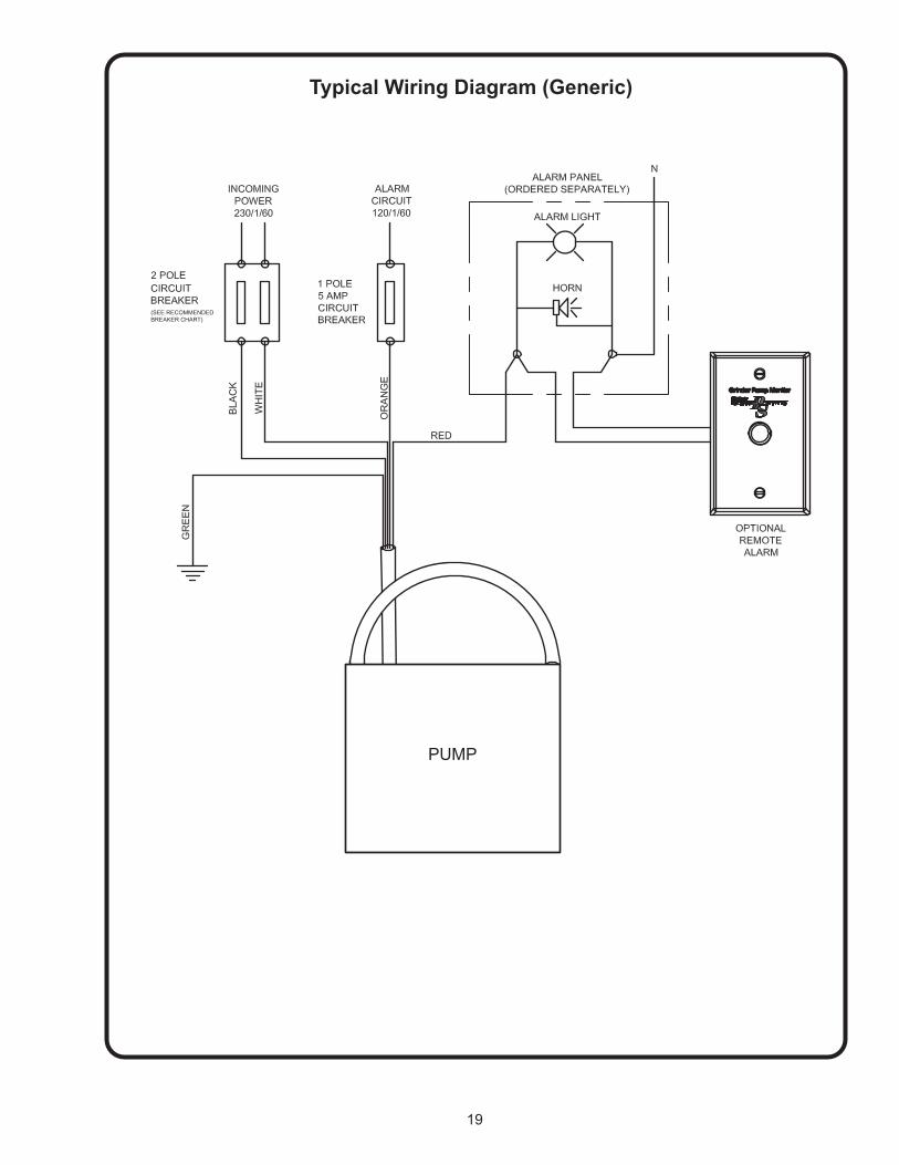
Typical Wiring Diagram (Generic)
PUMP
(SEE RECOMMENDED BREAKER CHART)

A Crane Co. Company 420 Third Street 83 West DrivePiqua, Ohio 45356 Brampton, Ont. Canada L6T 2J6(937) 778-8947 (905) 457-6223Fax (937) 773-7157 Fax (905) 457-2650www.cranepumps.com
Limited 3 Year WarrantyCrane Pumps & Systems warrants that products of our manufacture will be free of defects in material and workmanship under normal use and service for thirty-six (36) months after manufacture date, when installed and maintained in accordance with our instructions.This warranty gives you specific legal rights, and there may also be other rights which vary from state to state. In the event the product is covered by the Federal Consumer Product Warranties Law (1) the duration of any implied warranties associated with the product by virtue of said law is limited to the same duration as stated herein, (2) this warranty is a LIMITED WARRANTY, and (3) no claims of any nature whatsoever shall be made against us, until the ultimate consumer, his successor, or assigns, notifies us in writing of the defect, and delivers the product and/or defective part(s) freight prepaid to our factory or nearest authorized service station. Some states do not allow limitations on how long an implied warranty lasts, so the above limitation may not apply. THE SOLE AND EXCLUSIVE REMEDY FOR BREACH OF ANY AND ALL WARRANTIES WITH RESPECT TO ANY PRODUCT SHALL BE TO REPLACE OR REPAIR AT OUR ELECTION, F.O.B. POINT OF MANUFACTURE OR AUTHORIZED REPAIR STATION, SUCH PRODUCTS AND/OR PARTS AS PROVEN DEFECTIVE. THERE SHALL BE NO FURTHER LIABILITY, WHETHER BASED ON WARRANTY, NEGLIGENCE OR OTHERWISE. Unless expressly stated otherwise, guarantees in the nature of performance specifications furnished in addition to the foregoing material and workmanship warranties on a product manufactured by us, if any, are subject to laboratory tests corrected for field performance. Any additional guarantees, in the nature of performance specifications must be in writing and such writing must be signed by our authorized representative. Due to inaccuracies in field testing if a conflict arises between the results of field testing conducted by or for user, and laboratory tests corrected for field performance, the latter shall control. RECOMMENDATIONS FOR SPECIAL APPLICATIONS OR THOSE RESULTING FROM SYSTEMS ANALYSES AND EVALUATIONS WE CONDUCT WILL BE BASED ON OUR BEST AVAILABLE EXPERIENCE AND PUBLISHED INDUSTRY INFORMATION. SUCH RECOMMENDATIONS DO NOT CONSTITUTE A WARRANTY OF SATISFACTORY PERFORMANCE AND NO SUCH WARRANTY IS GIVEN.This warranty shall not apply when damage is caused by (a) improper installation, (b) improper voltage (c) lightning (d) excessive sand or other abrasive material (e) scale or corrosion build-up due to excessive chemical content. Any modification of the original equipment will also void the warranty. We will not be responsible for loss, damage or labor cost due to interruption of service caused by defective parts. Neither will we accept charges incurred by others without our prior written approval.This warranty is void if our inspection reveals the product was used in a manner inconsistent with normal industry practice and\or our specific recommendations. The purchaser is responsible for communication of all necessary information regarding the application and use of the product. UNDER NO CIRCUMSTANCES WILL WE BE RESPONSIBLE FOR ANY OTHER DIRECT OR CONSEQUENTIAL DAMAGES, INCLUDING BUT NOT LIMITED TO TRAVEL EXPENSES, RENTED EQUIPMENT, OUTSIDE CONTRACTOR FEES, UNAUTHORIZED REPAIR SHOP EXPENSES, LOST PROFITS, LOST INCOME, LABOR CHARGES, DELAYS IN PRODUCTION, IDLE PRODUCTION, WHICH DAMAGES ARE CAUSED BY ANY DEFECTS IN MATERIAL AND\OR WORKMANSHIP AND\OR DAMAGE OR DELAYS IN SHIPMENT. THIS WARRANTY IS EXPRESSLY IN LIEU OF ANY OTHER EXPRESS OR IMPLIED WARRANTY, INCLUDING ANY WARRANTY OF MERCHANTABILITY OR FITNESS FOR A PARTICULAR PURPOSE.No rights extended under this warranty shall be assigned to any other person, whether by operation of law or otherwise, without our prior written approval.

RETURNED GOODSRETURN OF MERCHANDISE REQUIRES A “RETURNED GOODS AUTHORIZATION”.
CONTACT YOUR LOCAL CRANE PUMPS & SYSTEMS, INC. DISTRIBUTOR.
Products Returned Must Be Cleaned, Sanitized, Or Decontaminated As Necessary Prior To Shipment, To Insure That Employees Will Not Be Exposed To Health Hazards In Handling Said Material. All Applicable Laws And Regulations Shall Apply.
IMPORTANT!WARRANTY REGISTRATION
Your product is covered by the enclosed Warranty.
If you have a claim under the provision of the warranty, contact your local Crane Pumps & Systems, Inc. Distributor.
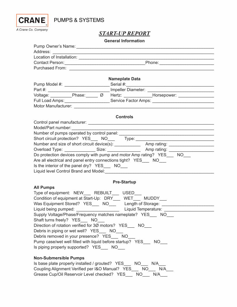
START-UP REPORTGeneral Information
Pump Owner’s Name: __________________________________________________________Address: ____________________________________________________________________Location of Installation: _________________________________________________________Contact Person: __________________________________Phone: _______________________Purchased From: _____________________________________________________________
Nameplate DataPump Model #: ___________________ Serial #: _____________________________________Part #: __________________________ Impeller Diameter: ____________________________Voltage: _________Phase: _____ Ø Hertz: ____________Horsepower: _______________Full Load Amps: ___________________ Service Factor Amps: __________________________Motor Manufacturer: ___________________________________________________________
ControlsControl panel manufacturer: _____________________________________________________Model/Part number: ____________________________________________________________Number of pumps operated by control panel: ________________________________________Short circuit protection? YES___ NO___ Type: _________________________________Number and size of short circuit device(s): ___________ Amp rating: ___________________Overload Type: _____________ Size: ______________ Amp rating: ___________________Do protection devices comply with pump and motor Amp rating? YES___ NO___Are all electrical and panel entry connections tight? YES___ NO___Is the interior of the panel dry? YES___ NO___Liquid level Control Brand and Model: ______________________________________________
Pre-StartupAll PumpsType of equipment: NEW___ REBUILT___ USED___Condition of equipment at Start-Up: DRY___ WET___ MUDDY___Was Equipment Stored? YES___ NO___ Length of Storage: ______________________Liquid being pumped: __________________ Liquid Temperature: _____________________Supply Voltage/Phase/Frequency matches nameplate? YES___ NO___Shaft turns freely? YES___ NO___ Direction of rotation verifi ed for 3Ø motors? YES___ NO___Debris in piping or wet well? YES___ NO___Debris removed in your presence? YES___ NO___Pump case/wet well fi lled with liquid before startup? YES___ NO___ Is piping properly supported? YES___ NO___
Non-Submersible PumpsIs base plate properly installed / grouted? YES___ NO___ N/A___Coupling Alignment Verifi ed per I&O Manual? YES___ NO___ N/A___Grease Cup/Oil Reservoir Level checked? YES___ NO___ N/A___
A Crane Co. Company

Submersible PumpsResistance of cable and pump motor (measured at pump control):Red-Black:_______Ohms(Ω) Red-White:_______Ohms(Ω) White-Black:_______Ohms(Ω)Resistance of Ground Circuit between Control Panel and outside of pump: __________Ohms(Ω)MEG Ohms check of insulation:Red to Ground: _________ White to Ground: __________ Black to Ground: ____________
Operational ChecksIs there noise or vibration present? YES___ NO___ Source of noise/vibration: ___________Does check valve operate properly? YES___ NO___ N/A___Is system free of leaks? YES___ NO___ Leaks at: ______________________________Does system appear to operate at design fl ow rate? YES___ NO___Nominal Voltage: _____________________ Phase: 1Ø 3Ø (select one)Voltage Reading at panel connection, Pump OFF: L1, L2 _____ L2, L3 ____ L1, L3 _____Voltage Reading at panel connection, Pump ON: L1, L2 ______ L2, L3 ____ L1, L3 _____Amperage Draw, Pump ON: L1 ____________ L2 _____________ L3 _____________
Submersible PumpsAre BAF and guide rails level / plumb? YES___ NO___Is pump seated on discharge properly? YES___ NO___Are level controls installed away from turbulence? YES___ NO___Is level control operating properly? YES___ NO___ Is pump fully submerged during operation? YES___ NO___
Follow up/Corrective Action RequiredYES___ NO___
Additional Comments:____________________________________________________________________________________________________________________________________________________________________________________________________________________________________________________________________________________________________________________________________________________________________________________________________________________________________________________________________________________________________________________________________________________
Startup performed by: _____________________ Date: ______________________________
Present at Start-Up( ) Engineer: ____________________________ ( ) Operator: ________________________
( ) Contractor: ____________________________ ( ) Other: ___________________________
All parties should retain a copy of this report for future trouble shooting/reference
A Crane Co. Company 420 Third Street 83 West DrivePiqua, Ohio 45356 Brampton, Ont. Canada L6T 2J6(937) 778-8947 (905) 457-6223Fax (937) 773-7157 Fax (905) 457-2650www.cranepumps.com

Notes


![PROSSER - Kuttkat · * 1863 Lichtenberg, Bez.Solka, Hztg.Bukowina [A] Maria Prosser * 1865 Lichtenberg, Bez.Solka, Hztg.Bukowina [A] Theresia Prosser * 1866 Lichtenberg, Bez.Solka,](https://img.pdfslide.net/doc/110x75/5f4bf2297c11ae244b2a3049/prosser-1863-lichtenberg-bezsolka-hztgbukowina-a-maria-prosser-1865.jpg)