Embed Size (px)
Citation preview

Pfahlsymposium, Braunschweig, 2013
1
Installation of Monopiles by Vibrohammers for the Riffgat Project
L. de Neef, P. Middendorp, J. Bakker, The Netherlands
1. Introduction
The successful installation of 22m diameter steel tubular piles/caissons by vibratory
hammers in China in 2011 resulted in a strong interest in the application of vibratory
hammers to install steel tubular monopiles for wind turbines, especially offshore. The
first such project, the Riffgat project in the North Sea, was successfully completed in
2012. This paper describes the project itself as well as the key elements in bringing it
to a successful completion.
Figure 1, Vibratory driving of 22 m diameter pile in China

Pfahlsymposium, Braunschweig, 2013
2
2. Hong Kong-Zhuhai-Macau Bridge, China
In November 2010 the companies APE, APE-Holland, APE-China and Allnamics
teamed up to convince the Chinese contractor First Harbor Marine Group China that
a massive multi-vibro hammer could be used to drive 49 m long, 22 m diameter steel
pipe piles weighing 600 tonnes each 25 m into the bed of the South China Sea,
where the soil consists of silty clay, clay and sand with SPT N-values ranging from 8
to 40.
Allnamics performed the vibratory driveability studies, using the AllWave-PDP
program, which showed the feasibility of driving these gigantic piles into the bottom of
the sea to the required depth.
On May 15, 2011 the world’s largest vibratory hammer drove the world’s largest pile
in 7½ minutes (Figure 1), just as the driveability studies performed by Allnamics had
predicted. At the highest production rate three piles were driven in a single day and
seven piles in three days, and within 7 months, on December 8, 2011, the APE
“Octakong” hammer drove the last of the 120 piles to the target penetration.
Figure 2, Vibro driving modeling for driveability predictions

Pfahlsymposium, Braunschweig, 2013
3
3. Riffgat Wind Farm Project
The Riffgat Wind Farm project is located in the North Sea near the German island of
Borkum and includes the installation of 30 steel monopiles on which 30 wind turbines
will be placed. The monopiles weigh between 480 and 720 tons, they are between 53
and 70 m long, with a diameter of 4.7 m at the top of the pile and between 5.7 and
6.5 m at the pile tip.
As a spin off from the successful vibratory driving at the Hong Kong-Zhuhai-Macau
Bridge project, the contractor Seaway Heavy Lifting chose the option of using a
vibratory hammer for the installation of the monopiles. By choosing this innovative
pile installation method they could adhere to the strict environmental rules which
apply in Germany and keep the environmental impact due to noise and vibrations
within acceptable limits, whereas traditional piling techniques with the conventional
hydraulic impact hammers would have resulted in noise levels that would have
caused major damage to marine life. Another advantage of vibratory driving is that
the pile can be repositioned easily when the initial installation angle is out of
specification, as was experienced during project execution.
Figure 3, SQK on deck and vibratory driving of monopile with SQK

Pfahlsymposium, Braunschweig, 2013
4
4. Soil investigation Riffgat
For the foundation design an extensive soil investigation was done, which included a
number of CPTs and borehole logs. From the interpretation of the field results three
distinct homogeneous zones were identified (identified as Homogenbereich I, II and
III in Figure 4):
Homogenbereich I comprises medium to dense packed sands up to and
beyond design level. Typical cone resistances vary between 10 and 75 MPa
and higher.
Homogenbereich II is inter-layered with highly consolidated stiff clay from 5 to
20 m below seabed.
Homogenbereich III reveals highly consolidated stiff clay from 10 m below
seabed up to and beyond design level.
Figure 4, Soil type zones

Pfahlsymposium, Braunschweig, 2013
5
Vibratory driving technique is especially suitable for granular non-cohesive soils, but
in cohesive soils the reduction in the oscillation amplitude might prevent the breaking
up of the inter-particle bonds. Therefore the overall success of the project would
hinge on successful installation in zones II and III and consequently these zones are
of particular interest for the driveability predictions
5. Driveability predictions
The contract for the vibratory hammers was awarded to APE-Holland, who
cooperated with Allnamics to carry out the driveability studies for the monopiles. To
model the transfer of forces to pile and soil properly, a wave equation (WEQ)
approach is required for such studies when the frequencies of the vibratory hammer
are in the range or higher than the lowest resonant frequency of the pile.
The WEQ prediction software package AllWave-PDP that was used for this project is
based on the Method of Characteristics (Middendorp 2004). In the model the pile is
subdivided into elements interacting with the soil at discrete points along the shaft
and at the toe, while soil resistance is modelled as a combination of springs, dampers
and masses.
To take into account soil fatigue as a result of the cyclic loading of the vibratory
hammer the Beta method (Fig.2) proposed by Jonker (1987) and Jonker and
Middendorp (1988) is applied.
Due to fatigue, yield stresses might be reduced considerably in sands, but much less
so in clays. This aspect combined with the higher damping values makes it more
difficult to penetrate clay layers as opposed to sand layers. This was reflected when
the driveability analysis was done for all three identified zones indicated in Figure 4:
as expected the simulations for Zone II and especially Zone III showed that it would
be more difficult to reach the required penetration depth.
However, the predictions indicated that a vibratory hammer with a (combined)
eccentric moment of 920 kg-m would be able to drive the monopiles in all 3 zones to
a minimum penetration at which the pile could be left free standing with sufficient
stability. To generate this combined eccentric moment APE-Holland developed a
Pfahlsymposium, Braunschweig, 2013
6
modular hammer specifically for this project: the Super Quad Kong (SQK, Figure 3),
a combination of four in-phase operating APE 600 vibrators.
Installation of the production piles was started in Zone I. As predicted the SQK could
install the piles to the required depth without any problems. As a matter of fact, for
these first piles, which were driven in sandy soils, only 50% of the total SQK power
was required and it was possible to drive the monopiles to a penetration of 31 meters
in one run. Nonetheless the client was still concerned about the installation in the
zones with clay and in order to reduce this concern it was decided to perform scaled
field tests in these zones.
Before the test piles were driven predictions were made for a steel pipe pile 1.22 m in
diameter driven with an APE 200-6 vibratory hammer (76 kg-m), and during
installation the test piles were monitored extensively, which included Vibratory Driving
Analysis (VDA). The VDA results were used in a signal matching procedure in which
the original soil model (used for the predictions) is modified (predominantly by
adjusting the fatigue and quake parameters) until the calculated computer results are
similar to the actual measurements. Next the simulations for the monopoles for
Zones II and III were rerun using the modified soil model, which indicated that the
conditions were slightly worse than originally predicted, but it was nevertheless
concluded that the SKQ could still drive the piles to a depth, which ensured a stable
situation when the pile was left free standing.
Based on these results the installation of production piles was started in Zones II and
III. No problems were encountered during the installation and the foundation of the
entire wind park was completed ahead of schedule.
The driveability predictions, especially in combination with VDA results in order to
fine-tune the initial predictions, have proven to be a cost effective and very powerful
tool to select the correct installation equipment and to prevent problems during
installation, which could result in downtime and delays with obviously serious
financial consequences.
Since the owner of the field required a blow count as indication of the pile bearing
capacity and since there was concern of soil strength degradation by vibratory

Pfahlsymposium, Braunschweig, 2013
7
driving, the last 10m of the piles still had to be driven with an impact hammer (using
an IHC S-1800 hydraulic hammer).
As part of the driveability studies Allnamics indicated that this was a rather
conservative approach, and this opinion was supported during actual driving by the
fact that the pile at the start of driving with the impact hammer showed a blow count
of 100 blows/25cm with an impact energy of 1200 kJ, which clearly demonstrated a
strong recovery of the soil strength after vibratory driving.
Moreover, before the hydrohammer could be applied, a Noise Mitigation System had
to be installed around the pile, which clearly showed the difference in environmental
impact between the two types of hammers.
Figure 5, NMS for impact pile driving

Pfahlsymposium, Braunschweig, 2013
8
Figure 6, SQK Vibratory hammer components
6. SQK Vibratory hammer set up
The APE Super Quad King consists
of:
A - Lifting frame which can also be
used for extraction up to 12 MN.
B - Four APE 600 vibratory hammers
working in tandem are placed on a
rigid steel framework.
C – Rigid framework, consisting of a
stiff and solid box to prevent flexing of
the pile.
D – Twelve hydraulic pile clamps, with
double cylinders and evenly
distributed along the pile perimeter.
It should be noted that the operation
of a vibratory hammer is different from
an impact hammer. Just resting the
vibratory hammer on top of the pile
while driving it is likely to result in
early refusal. Vibratory driving needs
acceleration and amplitude, and when
these motions are damped by the soil
the hammer should be lifted
somewhat to gain acceleration and amplitude again. Consequently successful
vibratory driving requires a crane operator familiar with the installation procedures for
vibratory driving.
Pfahlsymposium, Braunschweig, 2013
9
7. Learning loop
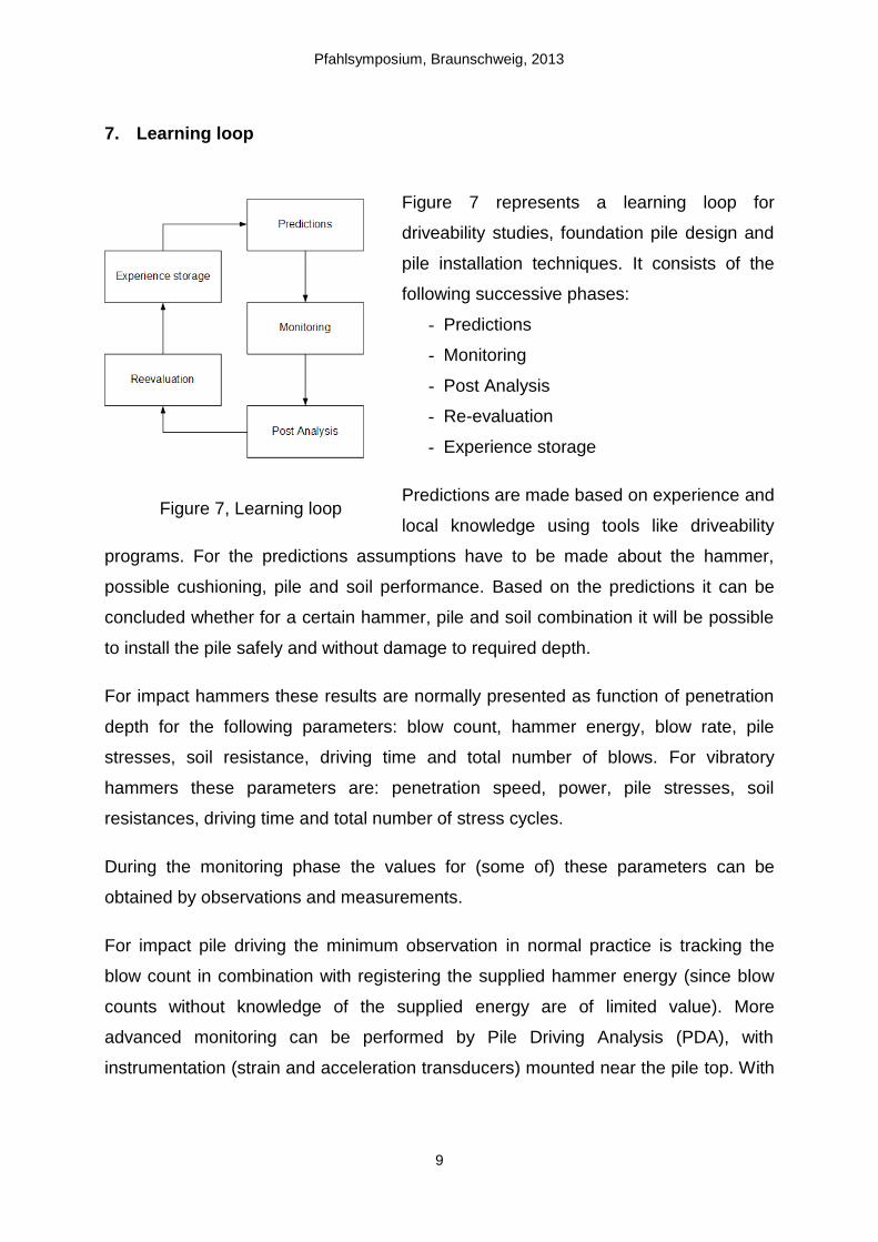
Figure 7 represents a learning loop for
driveability studies, foundation pile design and
pile installation techniques. It consists of the
following successive phases:
- Predictions
- Monitoring
- Post Analysis
- Re-evaluation
- Experience storage
Predictions are made based on experience and
local knowledge using tools like driveability
programs. For the predictions assumptions have to be made about the hammer,
possible cushioning, pile and soil performance. Based on the predictions it can be
concluded whether for a certain hammer, pile and soil combination it will be possible
to install the pile safely and without damage to required depth.
For impact hammers these results are normally presented as function of penetration
depth for the following parameters: blow count, hammer energy, blow rate, pile
stresses, soil resistance, driving time and total number of blows. For vibratory
hammers these parameters are: penetration speed, power, pile stresses, soil
resistances, driving time and total number of stress cycles.
During the monitoring phase the values for (some of) these parameters can be
obtained by observations and measurements.
For impact pile driving the minimum observation in normal practice is tracking the
blow count in combination with registering the supplied hammer energy (since blow
counts without knowledge of the supplied energy are of limited value). More
advanced monitoring can be performed by Pile Driving Analysis (PDA), with
instrumentation (strain and acceleration transducers) mounted near the pile top. With
Figure 7, Learning loop

Pfahlsymposium, Braunschweig, 2013
10
PDA impact force, pile stresses, transferred energy and soil resistance parameters
are obtained.
For vibratory driving the minimum observation is quite often just whether the vibratory
hammer was able to drive the pile to the required penetration. Recording the
penetration speed in combination with supplied power is rarely performed, while VDA
(using the strain transducers, but more sensitive acceleration transducers than used
in case of impact pile driving) is even rarer. However, with VDA force amplitude, pile
stresses, supplied power and hammer frequency information can be measured.
In the post analysis phase it is attempted to retrieve the soil model parameters from
the measured pile and soil responses. The standard technique for this process is
signal matching and the input for this process are the measurements obtained with
PDA or VDA.
In the re-evaluation phase the assumptions made during the prediction phase are
checked and obviously the knowledge gained should be stored and easily accessible
for the next prediction project.
Learning will only take place when all components of the learning curve are present.
For impact driving there have been many cases with all components present and a
lot has been learned from it. On the other hand, for vibratory driving there are only a
few of those complete learning cases and in most situations there is lack of feedback.
To contribute to the monitoring component of the learning loop the SQK was
equipped with sensors to measure hammer frequency and supplied power. However,
the Riffgat project team did not allow mounting of the transducers on the production
monopoles to allow for VDA. On several other wind turbine projects the authors also
noticed that mechanical engineers did not allow the drilling of about five 8 mm holes
to mount the transducers on the pile shaft with the argument of potential pile fatigue
life reduction, not taking into account the much lower (less fatigue inducing) stress
levels with vibratory driving. In this way valuable feedback data of the vibratory
driving process cannot be obtained and used for learning.

Pfahlsymposium, Braunschweig, 2013
11
8. VDA instrumentation and results
The vibratory driving analysis (VDA) instrumentation consists of combined
acceleration-strain transducers bolted on the pile shaft and a PDR (an advanced WiFi
Figure 9, PDR monitoring unit with Wi-Fi signal transmission for VDA
Figure 8, Combined acceleration/strain transducer for VDA
Figure 10, Time recordings from the scaled field test VDA

Pfahlsymposium, Braunschweig, 2013
12
based pile testing monitoring system for Pile Driving Analysis - for both impact and
vibratory hammers -, Dynamic Load Testing, and Rapid Load Testing) resiliently
suspended near the pile top. In case of vibratory driving the resulting signals are the
oscillating forces, pile top accelerations, velocities and displacement amplitudes.
Typical measured signals for the test pile on one of the Riffgat locations (R25) are
presented in Figure 10. The power transferred to the pile can be calculated by
multiplying the forces with the velocity signals. The pile penetration has to be
supplied manually to the monitoring software. Characteristic peak values of forces,
stresses, accelerations, velocities, displacements and penetration speed are
presented as function of penetration (Fig.11).
Figure 11, VDA monitoring results as function of pile penetration depth

Pfahlsymposium, Braunschweig, 2013
13
9. Vibratory Driving and impact driving
An extensive comparison between impact and vibratory driving will be published by
Fischer et.al. in 2013 and this document will discuss the influence on axial and lateral
pile capacities. However, in summary the advantages of vibratory driving are:
- Low stress levels compared to impact driving
- Pile material fatigue life friendly
- Short installation times especially in sandy soils
- Lower peak noise levels compared to impact pile driving
- Pile can be extracted and repositioned when required
- The chance on pile drops and pile runs is eliminated
while the advantages of impact driving are:
- Stiffer and harder soil types can be penetrated
- Availability of large databases with observations and monitoring feedback
- Driveability predictions calibrated on many projects
- Extensive offshore experience
It should be noted however, that the vibratory driving cannot fully replace impact pile
driving (e.g. in stiff clays and dense soil types impact hammers will be able to
penetrate deeper). At the same time an impact hammer should not be the standard
tool for each pile driving project: vibratory hammers and impact hammers should be
considered as complementary tools.
10. Conclusions
Powerful vibratory hammers allow the installation of large diameter steel
tubular piles.
The Riffgat pile installation process was completed with a vibratory hammer
ahead of schedule.
For vibratory driving more attention should be given to the learning
components like monitoring with VDA and the subsequent steps of the
learning loop (Post Analysis, Re-evaluation, and Experience storage) to reach
similar comfort zone for vibratory driveability predictions as exists for impact

Pfahlsymposium, Braunschweig, 2013
14
pile driving predictions Impact pile driving hammers and vibratory hammers
are complementary tools.
The driveability predictions, especially in combination with VDA results to fine-
tune the initial predictions, have proven to be a cost effective and a very
powerful tool to make the correct equipment selection and prevent installation
problems.
11. References
Jonker, G., Vibratory Pile Driving Hammers for Pile Installation and Soil
Improvement Projects., Proc. of Nineteenth Annual Offshore Technology Conf.,
Houston, Texas, OTC 5422, pp. 549-560, 1987
Jonker, G., Middendorp, P.,. Subsea installations using vibratory piling hammers,
20th OTC, Houston, Texas, 1988
Viking, K. Vibro-Driveability – a field study of vibratory driven sheet piles in non-
cohesive soils. Ph.D. Thesis 1002, Div. of Soil and Rock Mechanics, Royal Inst. of
Technology (KTH), Stockholm, Sweden, 2002
Holeyman, A. Vibratory driven piles, Vibratory Pile Driving and Deep Soil
Compaction, Balkema Publishers, Lisse 2002, pp 3 – 20
Fischer, J., Sychla, H., Bakker, J., Neef de, L., Stahlmann, J., A comparison
between impact driven and vibratory driven steel piles in the German North Sea,
Conference on Maritime Energy, Hamburg, 2013.