Embed Size (px)
Citation preview
OPTIC 3 Installation Guide onto Shimadzu GC-2010
INSTALLATION OF OPTIC 3 INJECTOR SYSTEM ONTO AN
SHIMADZU GC-2010 GAS CHROMATOGRAPH.
Please read the manual first before installation.
ATAS GL International B.V. De Run 4441 5503 LS Veldhoven Tel: +31 (0)40 254 95 31 Fax: +31 (0)40 254 97 79 [email protected]
Author : G.Alkema Quality Control Doc.id. : SM-040 Issue : 4 OPTIC 3 installation guide –
Shimadzu GC-2010 Page : 1 of 13
Date : 23-01-2007 Kit P/No: H500019 ATAS GL International

OPTIC 3 Installation Guide onto Shimadzu GC-2010
Author : G.Alkema Quality Control Doc.id. : SM-040 Issue : 4 OPTIC 3 installation guide –
Shimadzu GC-2010 Page : 2 of 13
Date : 23-01-2007 Kit P/No: H500019 ATAS GL International
Unpacking the installation kit Check for the following parts in the installation kit
Description
Quantity Part Number
Cable for OPTIC 3 – Shimatzu 2010 1 H400034 Mounting plate 1 H200034
Spacer with internal thread, M4x30x9
3
25 pin male sunD connector 1

OPTIC 3 Installation Guide onto Shimadzu GC-2010
Author : G.Alkema Quality Control Doc.id. : SM-040 Issue : 4 OPTIC 3 installation guide –
Shimadzu GC-2010 Page : 3 of 13
Date : 23-01-2007 Kit P/No: H500019 ATAS GL International
Pre-installation P1 Gases P1.1 Helium supply: 99.999% purity for the carrier gas on OPTIC 3. The carrier supply should be made available using 1/8” o.d. copper tubing. The maximum input pressure for the OPTIC 3 is 700 kPa (100 PSI). P1.2 A compressed air supply will be required for cooling the OPTIC 3 injector (or for
driving the liquid CO2 cooling valve when a liquid CO2 cooling kit, Pt.No.H500009 has been purchased).
The compressed air supply should be free of oil, water mist and particulate to ensure
reliable operation of the cooling system. The supply should be made available using 1/8” o.d. tubing. The operating pressure is 500 kPa (72 PSI) and the maximum inlet-pressure is 700 kPa (100 PSI).
P1.3 When an OPTIC 3 is to be used with a liquid CO2 sub ambient kit, please refer to the
CO2 kit installation manual. P2 Electrical Supply One mains supply socket will be required.
The OPTIC 3 has a universal electronic power supply and can be used with 110 V 60 Hz and 230 V 50Hz.
P3 Mounting Considerations P3.1 OPTIC 3 Injector Positioning. The Shimadzu GC-2010 has two injector positions available. The OPTIC 3 injector
will fit into both the injector positions. It is advisable with a DTD unit to install the injector in the front position.
P3.2 Control Module Positioning. The OPTIC 3 control module is usually placed on the left hand side of a Shimadzu
GC-2010. The dimensions of the control module are 43cm x 15cm x 43cm (h x w x d).
P4 GC and Autosampler I/O Requirements P4.1 If the OPTIC 3 is being mounted on a stand-alone chromatograph the “Cable for
OPTIC 3 - Shimadzu GC-2010” is required. (H400013) P4.2 If the installation is with a CombiPal, the “Cable for OPTIC 3 - Shimadzu GC-2010”
(H400013) is required and an extra cable between CombiPal and OPTIC 3 is required. (H400001)
P4.3 The combination of a Shimadzu autosampler and OPTIC 3 is not supported from
ATAS GL at the moment.

OPTIC 3 Installation Guide onto Shimadzu GC-2010
1 Safety
Before removing any cover from the gas chromatograph
Disconnect the mains supply Disconnect or de-pressurise any gas connections
Allow all ovens and heated zones to cool to a safe temperature Read the relevant sections of the gas chromatograph manual
2 Removal of Autosampler and/or MSD 2.1 If fitted, remove the autosampler and the autosampler mounting plate from the top the
GC oven, referring to the autosampler and/or GC manuals if required. 2.2 If fitted, the MSD may be removed if it obstructs the installation, refer to the GC
and/or manuals for information. (Usually no necessary) 3. Removing the inlet, pneumatics, and manifold
When no free position is available one of the injectors should be removed. If there is a free position available for the OPTIC 3, skip section 3.
3.1 Turn off the oven and the inlet and allow them to cool.
WARNING Turn off the oven and the inlet and allow them to cool. Turn off all flows at the initial gas supply. Then turn off the main power switch and unplug the power cord.
3.2 Remove the top cover, left side panel and the pneumatics chassis cover.
3.3 Remove the column. 3.4 Loosen the two screws, which secure the inlet to the oven,
and lift the inlet out of the oven. 3.5 Remove the heater and temperature sensor connector. 3.6 Remover the gasline blok attached at the regulator and remove the complete injector. 3.7 In order to prevent the G.C. reporting an electronic fault condition on the injector
removed above, a replacement plug should be placed. 4 Placing the GC thermocouple
Author : G.Alkema Quality Control Doc.id. : SM-040 Issue : 4 OPTIC 3 installation guide –
Shimadzu GC-2010 Page : 4 of 13
Date : 23-01-2007 Kit P/No: H500019 ATAS GL International

OPTIC 3 Installation Guide onto Shimadzu GC-2010
In order to have an accurate constant column flow, it is necessary to know the GC
column oven temperature. This is measured with a thermocouple supplied with the OPTIC 3.
4.1 Find a hole in the GC oven top and guide the thermocouple trough the wall inside the
GC oven. Or place the thermocouple near the injector and guide it inside the GC oven.
4.2 Fix the thermocouple end some where in the GC oven so it’s measuring the oven
temperature in a good way. Take care that the end of the thermocouple is not in contact with metal.
4.3 Route the thermocouple cable to the back of the host chromatograph. 4.4 Connect the thermocouple plug to the thermocouple socket on the rear panel of the
OPTIC 3 control module. Note that it is important to ensure that the correct connector is used.
Warning: Do not use the connector for the Injector thermocouple. 5 Mounting the OPTIC 3 Injector 5.1 Place the insulation material supplied with the installation kit in the hole where the
injector should be installed. 5.2 Mount the installation bracket and place the tree 30mm spacers. 5.3 Place the injector in the position prepared and fix it using the 3 M4x10 screws
supplied with the injector kit. 6 Gas Control Connection to the Injector 6.1 The pipe work from the OPTIC 3 injector will be connected to the ports on the rear of
the control module. 6.2 The injector top should be located and the pipe work uncoiled. Re-fit the injector top. 6.3 Form the pipe work neatly on the oven top and route the pipe work such that it may
be connected to the ports on the rear of the control module. 6.4 The carrier out, split, pressure and septum purge ports on the rear of the control
module have been fitted with appropriate reducing ferrules to enable direct connection to 1/16” o.d. pipe work.
6.5 Connect the split line from the OPTIC 3 injector (with an “Split” identifier) to the
Control module “Split” port using the PTFE reducing ferrule supplied with the injector.
Author : G.Alkema Quality Control Doc.id. : SM-040 Issue : 4 OPTIC 3 installation guide –
Shimadzu GC-2010 Page : 5 of 13
Date : 23-01-2007 Kit P/No: H500019 ATAS GL International

OPTIC 3 Installation Guide onto Shimadzu GC-2010
Do not push the split line to much inside the ferrule so it is touching the metal of the coupling. Make sure there is an electrical insulation between the control module and the OPTIC 3 injector split line.
6.6 Connect the carrier line (with a “Carrier” identifier) to the “Carrier Out” port on the control module.
6.7 Connect the septum purge line (with “Septum Purge” identifier) to the “Aux Gas In /
Purge In” port on the control module. As the standard, there is a fixed restrictor installed allowing a few ml/min septum purge flow.
7 Cooling Air 7.1 Connect the 1/8” o.d. Nylon pipe supplied with the injector to the “To Injector” port on
the cooling solenoid on the control module rear panel. 7.2 Route the cooling air line to the injector. It is suggested that a similar route to the
carrier, pressure, split and purge lines is chosen. 7.3. Fit the cooling tube to the cooling pipe. Take care not to brake the cooling pipe on the
welding. 7.4 The cooling pipe should be positioned such that the outlet projects down into the cup
of the OPTIC 3 injector and is approximately level with the injector central tube when the injector is viewed from above. Ensure that the end of the cooling tube does not come into contact with the central tube of the injector when the cooling pipe is secured in place. The cooling air should not blow direct on the thermocouple.
7.5 The cooling air line can be cut to length using a sharp knife to improve the neatness
of the installation before the outlet end of the Nylon line is pushed over the inlet end of the cooling pipe. A secure connection will be ensured if the nylon pipe overlaps the cooling pipe by 10-12 mm.
9 Connections of Injector Power and Thermocouple Cables 9.1 Route the injector thermocouple cable under the back cover and of the host
chromatograph. 9.2 Connect the thermocouple plug to the thermocouple socket on the rear panel of the
OPTIC 3 control module. Note that it is important to ensure that the correct connector is used.
Warning: Do not use the connector for the GC thermocouple.
Author : G.Alkema Quality Control Doc.id. : SM-040 Issue : 4 OPTIC 3 installation guide –
Shimadzu GC-2010 Page : 6 of 13
Date : 23-01-2007 Kit P/No: H500019 ATAS GL International

OPTIC 3 Installation Guide onto Shimadzu GC-2010
Figure 1. 9.3 Route the injector power cable (flat blue cable sleeved with a braided glass fibre
sheath) to the injector and connect the connectors to the OPTIC 3 injector. See figure 1.
9.4 Take care that the heater cable clamps are not in contact with the top-boss clamp nut
or the central tube. If this happens, there is a short cut and the injector will not perform well.
9.5 Secure connections between the power cable and the injector are necessary for
reliable operation of the system. (Torque settings 5lb/inches [58grms/meter]) Connections that are insufficiently tight will cause increased contact resistance and may cause the connections to overheat. Note, however, that overtightening the power cable fixing nuts may cause damage to the threads on the mounting studs which may require replacement of the injector.
10 Connection of Helium and Cooling Air Supplies 10.1 Connect a supply of helium of a suitable quality at a pressure between 200 and 700
kPa to the “Carrier IN” port on the rear of the control module using the copper tube supplied. Note that the maximum pressure that can be set using the OPTIC 3 gas control will be approximately 5 psi less than the carrier gas supply pressure. As a result a low carrier supply pressure may limit the flexibility of the equipment.
10.2 Connect a supply of cooling air to the “Air In” port on the cooling solenoid on the rear
of the control module at a pressure between 400 and 500 kPa. Lower pressure can be used if decreased cooling performance is acceptable.
Author : G.Alkema Quality Control Doc.id. : SM-040 Issue : 4 OPTIC 3 installation guide –
Shimadzu GC-2010 Page : 7 of 13
Date : 23-01-2007 Kit P/No: H500019 ATAS GL International
OPTIC 3 Installation Guide onto Shimadzu GC-2010
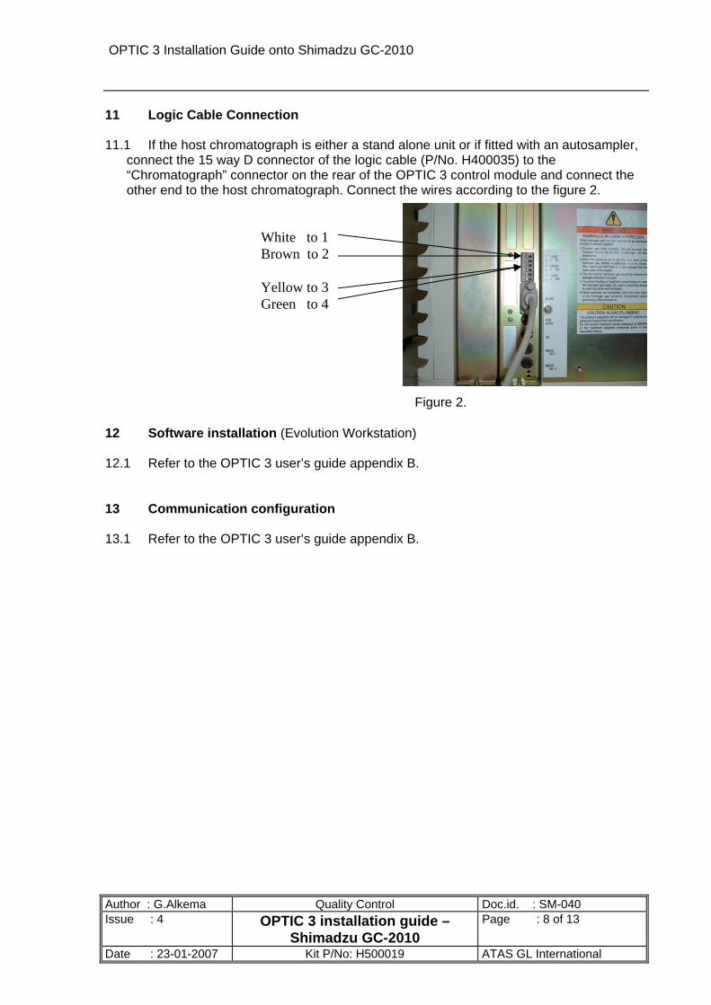
11 Logic Cable Connection 11.1 If the host chromatograph is either a stand alone unit or if fitted with an autosampler,
connect the 15 way D connector of the logic cable (P/No. H400035) to the “Chromatograph” connector on the rear of the OPTIC 3 control module and connect the other end to the host chromatograph. Connect the wires according to the figure 2.
White to 1
Brown to 2 Yellow to 3 Green to 4
Figure 2. 12 Software installation (Evolution Workstation) 12.1 Refer to the OPTIC 3 user’s guide appendix B. 13 Communication configuration 13.1 Refer to the OPTIC 3 user’s guide appendix B.
Author : G.Alkema Quality Control Doc.id. : SM-040 Issue : 4 OPTIC 3 installation guide –
Shimadzu GC-2010 Page : 8 of 13
Date : 23-01-2007 Kit P/No: H500019 ATAS GL International
OPTIC 3 Installation Guide onto Shimadzu GC-2010
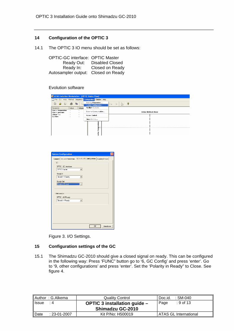
14 Configuration of the OPTIC 3 14.1 The OPTIC 3 IO menu should be set as follows: OPTIC-GC interface: OPTIC Master Ready Out: Disabled Closed Ready In: Closed on Ready Autosampler output: Closed on Ready
Evolution software
Figure 3. I/O Settings. 15 Configuration settings of the GC 15.1 The Shimadzu GC-2010 should give a closed signal on ready. This can be configured
in the following way: Press ‘FUNC” button go to ‘6, GC Config’ and press ‘enter’. Go to ‘9, other configurations’ and press ‘enter’. Set the ‘Polarity in Ready” to Close. See figure 4.
Author : G.Alkema Quality Control Doc.id. : SM-040 Issue : 4 OPTIC 3 installation guide –
Shimadzu GC-2010 Page : 9 of 13
Date : 23-01-2007 Kit P/No: H500019 ATAS GL International

OPTIC 3 Installation Guide onto Shimadzu GC-2010
Figure 4. Cable when AOC 20i is used Use the start and ready calbe from Shimadzu supplied with the sampler. Solder this cable to the 25 pin male subD connector supplied with this kit. Pin number (OPTIC) Colour autosampler cable
1 White 2 Black 6 Yellow 5 Red
Connect the 25 pin connector on the back of the OPTIC control box, using the autosampler port. 16 Testing 16.1 Fit an O ring to a liner and place the liner in the injector, ensuring that the notch at the
end of the liner is towards the bottom of the injector. 16.2 Fit the white PTFE insulating washer to the top of the injector base before securing
the injector top to the injector base. Note that excessive tightening of the top boss clamp nut is unnecessary to form a seal between the top and bottom halves of the injector.
16.3 Refit the covers to the host chromatograph, routing the OPTIC 3 cables and pipework
under the injector mouldings and covers if appropriate. Tywraps are provided to allow the cables and pipework to be clipped together to ensure a tidy installation. Refit the injector moulding and cover or autosampler mounting plate.
Author : G.Alkema Quality Control Doc.id. : SM-040 Issue : 4 OPTIC 3 installation guide –
Shimadzu GC-2010 Page : 10 of 13
Date : 23-01-2007 Kit P/No: H500019 ATAS GL International

OPTIC 3 Installation Guide onto Shimadzu GC-2010
Author : G.Alkema Quality Control Doc.id. : SM-040 Issue : 4 OPTIC 3 installation guide –
Shimadzu GC-2010 Page : 11 of 13
Date : 23-01-2007 Kit P/No: H500019 ATAS GL International
16.4 Fit a capillary column to the injector and check the pipework for leaks. An electronic Leakseeker or 50/50 isopropanol/water should be used for leak checking. Under no circumstances should soap solution or other proprietary leak detector fluid be applied to couplings in the piping system.
16.5 Run a test sample of known composition to test the system chromatographically and
to check logic connections between the OPTIC 3, host chromatograph and auto sampler, where fitted.
OPTIC 3 Installation Guide onto Shimadzu GC-2010
Author : G.Alkema Quality Control Doc.id. : SM-040 Issue : 4 OPTIC 3 installation guide –
Shimadzu GC-2010 Page : 12 of 13
Date : 23-01-2007 Kit P/No: H500019 ATAS GL International
17 Testing the OPTIC 3 communication in a system. (Ready Input & Ready Output)
In principal there are two system possibilities, depending on the hardware.
17.1 The OPTIC 3 is Master:
The auto sampler waits for the OPTIC to be Ready and the OPTIC waits for the GC to be Ready. Auto sampler starts the OPTIC; OPTIC starts the GC; GC starts data-acquisition. Testing: Turn the GC oven to OFF; set the data-acquisition software to ready; start a CombiPal method; Start an OPTIC method. The CombiPal should wait; the OPTIC should wait (Initialising on the display of the OPTIC). Turn the GC oven back to on. When the GC gets Ready, the OPTIC gets Ready and the CombiPal will start. Check the start sequence as described above.
17.2 When the original Shimadzu sampler is used there is the same sequence as with a
CombiPal. To check the communication with the original Shimadzu sampler see 16.1. The installation is now complete.
If you have suggestions for this manual please mail to [email protected]
OPTIC 3 Installation Guide onto Shimadzu GC-2010
Author : G.Alkema Quality Control Doc.id. : SM-040 Issue : 4 OPTIC 3 installation guide –
Shimadzu GC-2010 Page : 13 of 13
Date : 23-01-2007 Kit P/No: H500019 ATAS GL International
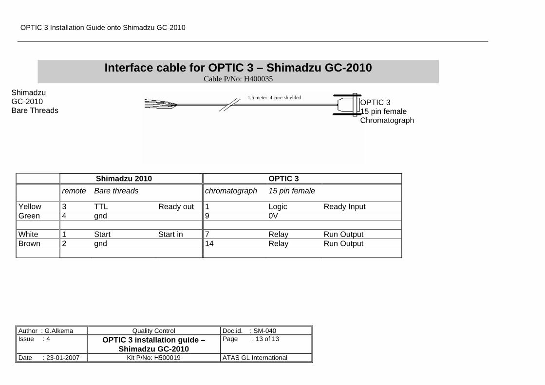
Interface cable for OPTIC 3 – Shimadzu GC-2010 Cable P/No: H400035
Shimadzu GC-2010 Bare Threads
1,5 meter 4 core shielded OPTIC 3 15 pin female Chromatograph
Shimadzu 2010 OPTIC 3 remote Bare threads chromatograph 15 pin female
Yellow 3 TTL Ready out 1 Logic Ready Input Green 4 gnd 9 0V White 1 Start Start in 7 Relay Run Output Brown 2 gnd 14 Relay Run Output