Embed Size (px)
Citation preview
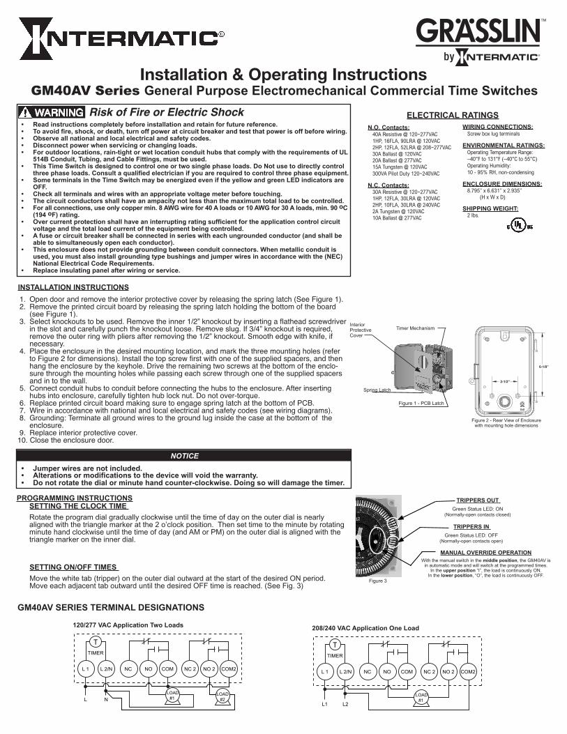
Installation & Operating InstructionsGM40AV Series General Purpose Electromechanical Commercial Time Switches
• Read instructions completely before installation and retain for future reference.• To avoid fire, shock, or death, turn off power at circuit breaker and test that power is off before wiring.• Observe all national and local electrical and safety codes.• Disconnect power when servicing or changing loads.• For outdoor locations, rain-tight or wet location conduit hubs that comply with the requirements of UL
514B Conduit, Tubing, and Cable Fittings, must be used. • This Time Switch is designed to control one or two single phase loads. Do Not use to directly control
three phase loads. Consult a qualified electrician if you are required to control three phase equipment.• Some terminals in the Time Switch may be energized even if the yellow and green LED indicators are
OFF. • Check all terminals and wires with an appropriate voltage meter before touching.• The circuit conductors shall have an ampacity not less than the maximum total load to be controlled.• For all connections, use only copper min. 8 AWG wire for 40 A loads or 10 AWG for 30 A loads, min. 90 oC
(194 oF) rating.• Over current protection shall have an interrupting rating sufficient for the application control circuit
voltage and the total load current of the equipment being controlled.• A fuse or circuit breaker shall be connected in series with each ungrounded conductor (and shall be
able to simultaneously open each conductor).• This enclosure does not provide grounding between conduit connectors. When metallic conduit is
used, you must also install grounding type bushings and jumper wires in accordance with the (NEC) National Electrical Code Requirements.
• Replace insulating panel after wiring or service.
WARNING
1. Open door and remove the interior protective cover by releasing the spring latch (See Figure 1). 2. Remove the printed circuit board by releasing the spring latch holding the bottom of the board (see Figure 1). 3. Select knockouts to be used. Remove the inner 1/2” knockout by inserting a flathead screwdriver in the slot and carefully punch the knockout loose. Remove slug. If 3/4” knockout is required, remove the outer ring with pliers after removing the 1/2” knockout. Smooth edge with knife, if necessary. 4. Place the enclosure in the desired mounting location, and mark the three mounting holes (refer to Figure 2 for dimensions). Install the top screw first with one of the supplied spacers, and then hang the enclosure by the keyhole. Drive the remaining two screws at the bottom of the enclo- sure through the mounting holes while passing each screw through one of the supplied spacers and in to the wall. 5. Connect conduit hubs to conduit before connecting the hubs to the enclosure. After inserting hubs into enclosure, carefully tighten hub lock nut. Do not over-torque. 6. Replace printed circuit board making sure to engage spring latch at the bottom of PCB. 7. Wire in accordance with national and local electrical and safety codes (see wiring diagrams). 8. Grounding: Terminate all ground wires to the ground lug inside the case at the bottom of the enclosure. 9. Replace interior protective cover. 10. Close the enclosure door.
INSTALLATION INSTRUCTIONS
Figure 2 - Rear View of Enclosure with mounting hole dimensions
6-1/8”
2-1/2”
Figure 1 - PCB Latch
Interior Protective Cover
Timer Mechanism
Spring Latch
SETTING THE CLOCK TIME
Rotate the program dial gradually clockwise until the time of day on the outer dial is nearly aligned with the triangle marker at the 2 o’clock position. Then set time to the minute by rotating minute hand clockwise until the time of day (and AM or PM) on the outer dial is aligned with the triangle marker on the inner dial.
PROGRAMMING INSTRUCTIONS
TRIPPERS IN Green Status LED: OFF
(Normally-open contacts open)
TRIPPERS OUT Green Status LED: ON
(Normally-open contacts closed)
MANUAL OVERRIDE OPERATIONWith the manual switch in the middle position, the GM40AV is
in automatic mode and will switch at the programmed times. In the upper position “I”, the load is continuously ON.
In the lower position, “O”, the load is continuously OFF.
• Jumper wires are not included.• Alterations or modifications to the device will void the warranty.• Do not rotate the dial or minute hand counter-clockwise. Doing so will damage the timer.
NOTICE
GM40AV SERIES TERMINAL DESIGNATIONS
NO 2NC 2NONCL 2/NL 1
TTIMER
L N
COM
LOAD #1
LOAD #2
COM2
120/277 VAC Application Two Loads
COM2NO 2NC 2NONCL 2/NL 1
TTIMER
L1 L2
COM
LOAD #1
208/240 VAC Application One Load
N.O. Contacts: 40A Resistive @ 120~277VAC 1HP, 16FLA, 90LRA @ 120VAC 2HP, 12FLA, 52LRA @ 208~277VAC 30A Ballast @ 120VAC 20A Ballast @ 277VAC 15A Tungsten @ 120VAC 300VA Pilot Duty 120~240VAC
N.C. Contacts: 30A Resistive @ 120~277VAC 1HP, 12FLA, 30LRA @ 120VAC 2HP, 10FLA, 30LRA @ 240VAC 2A Tungsten @ 120VAC 10A Ballast @ 277VAC
WIRING CONNECTIONS: Screw box lug terminals
ENVIRONMENTAL RATINGS: Operating Temperature Range: –40°F to 131°F (–40°C to 55°C) Operating Humidity: 10 - 95% RH, non-condensing
ENCLOSURE DIMENSIONS: 8.795” x 6.631” x 2.935” (H x W x D)
SHIPPING WEIGHT: 2 lbs.
SETTING ON/OFF TIMES
Move the white tab (tripper) on the outer dial outward at the start of the desired ON period. Move each adjacent tab outward until the desired OFF time is reached. (See Fig. 3)
ELECTRICAL RATINGS
Figure 3
Risk of Fire or Electric Shock
INSTRUCCIONES DE INSTALACIÓN Y OPERACIÓN
Serie GM40AV Uso general Interruptores de tiempo electrómecanico comerciales
• Lealasinstruccionescompletasantesdeinstalaryconsérvelasparareferenciasfuturas. • Paraevitarelriesgodeincendio,descargaeléctricaomuerte,apagueelsuministroeléctricodel cortacircuitoycompruebequeelsuministroestéapagadoantesdecomenzarainstalarelcableado. • Respetetodosloscódigosdeelectricidadyseguridadnacionalesylocales. • Desconecteelsuministroeléctricocuandolleveacabomantenimientoorealiceuncambiodelacarga. • Paralasubicacionesenexteriores,sedeberánusarconcentradoresdeconductocontraaguao humedadquecumplanconlosrequisitosdeconductosUL514B,tuberíayaccesoriosparacable. • Esteinterruptordetiempoestádiseñadoparacontrolarunaodoscargasdefasesencilla.Nose useparacontrolardirectamentecargasdetresfases.Consulteaunelectricistacapacitadosisele requierecontrolarequiposdetresfases. • Algunasterminalesdelinterruptordetiempopuedentenerenergíainclusosilosdiodosemisores deluzindicadoresestánDESACTIVADOS. • Verifiquetodaslasterminalesycablesconunverificadordevoltajeadecuadoantesdetocarlos. • Losconductoresdecircuitotendránunaampacidadnomenorquelacargatotalmáximaacontrolar. • Paratodaslasconexiones,usecomomínimouncablede8AWGparacargasde40Aode10AWG paracargasde30A,unaclasificaciónmínimade90oC(194oF). • Laproteccióncontrasobrecorrientestendráunrangodeinterrupciónsuficienteparaelvoltajede circuitodecontroldelaaplicaciónylacorrientedelacargatotaldelequipoqueseesté controlando. • Seconectaráunfusibleocortacircuitosenserieconcadaconductorsinconexiónatierra(yéste podráabrircadaconductorenformasimultánea). • Estacajanoproporcionaunaconexiónatierraentrelosconectoresdelconducto.Cuandoseusan conductosmetálicos,tambiénsedebeninstalarcasquillosdeconexiónatierraycablesde acoplamiento,segúnlosrequisitosdeCódigoEléctricoNacional(NEC,porsussiglaseninglés). • Reemplaceelpaneldeaislamientodespuésderealizarelcableadooelmantenimiento.
ADVERTENCIA Riesgo de incendio o descarga eléctrica N.O. Contactos: Resistencia de 40 A a 120~277 VAC 1 HP, 16 FLA, 90 LRA a 120 VAC 2 HP, 12 FLA, 52 LRA a 208~277 VAC Balastra de 30 A a 120 VAC Balastra de 20 A a 277 VAC Tungsteno de 15 A a 120 VAC Relé auxiliar de 300 VA a 120~240 VAC
N.C. Contactos: Resistencia de 30A a 120~277 VAC 1 HP, 12 FLA, 30 LRA a 120 VAC 2 HP, 10 FLA, 30 LRA a 240 VAC Tungsteno de 2A a 120 VAC Balastra de 10A a 277 VAC
CONEXIONES DEL CABLEADO: Terminales de puesta a tierra en caja con tornillo
CAPACIDADES NOMINALES AMBIENTALES: Rango de temperatura operativa: -40°F a 131°F (-40°C a 55°C) Humedad operativa: 10 - 95% RH, sin condensación
DIMENSIONES DE LA CARCASA: 8.795” x 6.631” x 2.935” (A x A x P)
PESO AL EMBARQUE: 2 lbs.
CAPACIDAD ELÉCTRICA NOMINAL
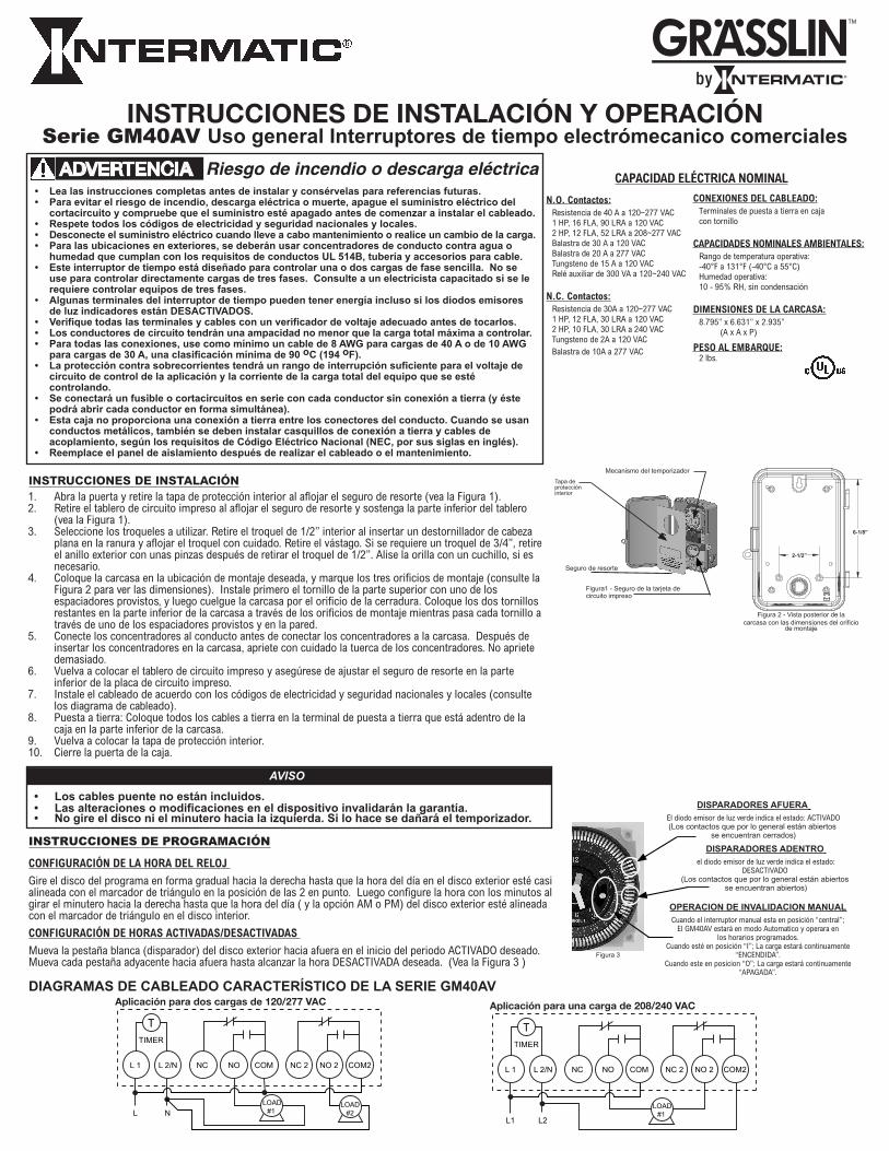
1. Abra la puerta y retire la tapa de protección interior al aflojar el seguro de resorte (vea la Figura 1).2. Retire el tablero de circuito impreso al aflojar el seguro de resorte y sostenga la parte inferior del tablero
(vea la Figura 1).3. Seleccione los troqueles a utilizar. Retire el troquel de 1/2” interior al insertar un destornillador de cabeza
plana en la ranura y aflojar el troquel con cuidado. Retire el vástago. Si se requiere un troquel de 3/4”, retire el anillo exterior con unas pinzas después de retirar el troquel de 1/2”. Alise la orilla con un cuchillo, si es necesario.
4. Coloque la carcasa en la ubicación de montaje deseada, y marque los tres orificios de montaje (consulte la Figura 2 para ver las dimensiones). Instale primero el tornillo de la parte superior con uno de los espaciadores provistos, y luego cuelgue la carcasa por el orificio de la cerradura. Coloque los dos tornillos restantes en la parte inferior de la carcasa a través de los orificios de montaje mientras pasa cada tornillo a través de uno de los espaciadores provistos y en la pared.
5. Conecte los concentradores al conducto antes de conectar los concentradores a la carcasa. Después de insertar los concentradores en la carcasa, apriete con cuidado la tuerca de los concentradores. No apriete demasiado.
6. Vuelva a colocar el tablero de circuito impreso y asegúrese de ajustar el seguro de resorte en la parte inferior de la placa de circuito impreso.
7. Instale el cableado de acuerdo con los códigos de electricidad y seguridad nacionales y locales (consulte los diagrama de cableado).
8. Puesta a tierra: Coloque todos los cables a tierra en la terminal de puesta a tierra que está adentro de la caja en la parte inferior de la carcasa.
9. Vuelva a colocar la tapa de protección interior. 10. Cierre la puerta de la caja.
INSTRUCCIONES DE INSTALACIÓN
6-1/8”
2-1/2”
CONFIGURACIÓN DE LA HORA DEL RELOJ
Gire el disco del programa en forma gradual hacia la derecha hasta que la hora del día en el disco exterior esté casi alineada con el marcador de triángulo en la posición de las 2 en punto. Luego configure la hora con los minutos al girar el minutero hacia la derecha hasta que la hora del día ( y la opción AM o PM) del disco exterior esté alineada con el marcador de triángulo en el disco interior.
CONFIGURACIÓN DE HORAS ACTIVADAS/DESACTIVADAS
Mueva la pestaña blanca (disparador) del disco exterior hacia afuera en el inicio del periodo ACTIVADO deseado. Mueva cada pestaña adyacente hacia afuera hasta alcanzar la hora DESACTIVADA deseada. (Vea la Figura 3 )
INSTRUCCIONES DE PROGRAMACIÓN
Tapa de protección interior
Mecanismo del temporizador
Figura 2 - Vista posterior de la carcasa con las dimensiones del orificio
de montaje
Seguro de resorte
Figura1 - Seguro de la tarjeta de circuito impreso
• Loscablespuentenoestánincluidos.• Lasalteracionesomodificacioneseneldispositivoinvalidaránlagarantía.• Nogireeldisconielminuterohacialaizquierda.Silohacesedañaráeltemporizador.
AVISO
DISPARADORESADENTRO el diodo emisor de luz verde indica el estado:
DESACTIVADO (Los contactos que por lo general están abiertos
se encuentran abiertos)
OPERACIONDEINVALIDACIONMANUALCuando el interruptor manual esta en posición “central”;
El GM40AV estará en modo Automatico y operara en los horarios programados.
Cuando esté en posición “I”; La carga estará continuamente “ENCENDIDA”.
Cuando este en posicion “O”; La carga estará continuamente “APAGADA”.
DIAGRAMASDECABLEADOCARACTERÍSTICODELASERIEGM40AV
NO 2NC 2NONCL 2/NL 1
TTIMER
L N
COM
LOAD #1
LOAD #2
COM2 COM2NO 2NC 2NONCL 2/NL 1
TTIMER
L1 L2
COM
LOAD #1
Aplicación para dos cargas de 120/277 VAC Aplicación para una carga de 208/240 VAC
Série de GM40AVCommutateurshorairescommerciauxélectromécaniquesd’usageuniversel.
Figura 3
DISPARADORESAFUERA El diodo emisor de luz verde indica el estado: ACTIVADO (Los contactos que por lo general están abiertos
se encuentran cerrados)
DIRECTIVES D’INSTALLATION ET DE FONCTIONNEMENTSérie de GM40AVCommutateurshorairescommerciauxélectromécaniquesd’usageuniversel.
Contacts N.O. : 40 A résistifs à 120-277 volts c.a. 1 HP, 16 FLA, 90 LRA à 120 volts c.a. 2 HP, 12 FLA, 52 LRA à 208-277 volts c.a. 30 A Ballast à 120 volts c.a. 20 A Ballast à 277 volts c.a. 15 A tungstène à 120 volts c.a. 300 VA commande pilote 120-240 volts c.a. Contacts N.C. : 30 A résistifs à 120-277 volts c.a. 1 HP, 12 FLA, 30 LRA à 120 volts c.a. 2 HP, 10 FLA, 30 LRA à 240 volts c.a. 2 A tungstène à 120 volts c.a. 10 A Ballast à 277 volts c.a.
CONNEXIONS DU CÂBLAGE : Bornes à vis
CARACTÉRISTIQUES NOMINALES : Échelle de température de fonctionnement : -40°C à 55°C (-40°F à 131°F) Humidité de fonctionnement : 10 - 95 % HR, sans condensation
DIMENSIONS DU BOÎTIER : 22,34 x 16,84 x 7,45 cm (8,795 x 6,631 x 2,935 po) (H x L x P)
POIDS D’EXPÉDITION : 0,907 kg (2 livres)
CARACTÉRISTIQUES NOMINALES
6-1/8”
2-1/2”
Figure 2 - Vue arrière du boîtier et dimensions des orifices de montage
Cache intérieur de protection
Mécanisme de la minuterie
Verrou à ressort
Figure 1 - Verrou de la carte imprimée
• Lisezentièrementlesinstructionsavantdeprocéderàl’installationetconservercelles-cienvue d’uneréférenceultérieure.• Pouréviterlesrisquesd’incendie,d’électrocutionoudemort,coupezlecourantaudisjoncteuret vérifiezl’absencedecourantavantdeprocéderaucâblage.• Respecteztouteslesnormesélectriquesetdesécuriténationalesetlocales.• Coupezlecourantpendantuneréparationouunchangementdecharge.• Pourlesemplacementsenextérieur,étanchesàlapluieouhumides,vousdevezutiliserdes entréesdeconduitrespectantlesexigencesdesconduits,tuyauxetraccordsUL514B.• Cetteminuterieestconçuepourcontrôlerdeschargesmonophaséesoubiphasées.Nel’utilisez paspourcontrôlerdirectementdeschargestriphasées.Consultezunélectricienqualifiésivous devezcontrôlerunéquipmenttriphasé.• CertainesbornesdelaminuteriesontalimentéesmêmesilesDELjauneetvertesontÉTEINTES.• Vérifieztouslescâblesetbornesàl’aided’unvoltmètreappropriéavantdelestoucher.• L’intensitéadmissibledesconducteursducircuitnedoitpasëtreinférieureàl’intensitétotale maximaleàcontrôler.• Pourtouteslesconnexions,utilisezuncâbled’aumoins8AWGpouruneintensitéde40Aou10 AWGpouruneintensitéde30A,pourunetempératurenominalemin.de90˚C(194˚F).• Lepouvoirdecouprenominaldelaprotectioncontrelessurintensitésdoitêtresuffisantpourla tensionducircuitdecontrôleetlatensiontotaledel’équipmentsouscontrôle.• Undisjoncteur(pourlecircuitoulesfusibles)doitêtreconnectéensérieàchaqueconducteurnon reliéàlaterre(etdoitêtrecapabled’ouvrirchaqueconducteursimultanément).• Ceboîtiern’estpaspourvud’unemiseàlaterreentrelesconnecteursdesconduits.Lorsq’un conduitmétalliqueestutilisé,ilfautaussiinstallerunemiseàlaterredetypebagueetcâblede liaisonconformémentauxexigencesduCodenationaldel’électricité.• Replacerlepanneauisolantaaprèsavoireffectuélecâblageoul’entretien.
AVERTISSEMENT Risque d’incendie ou de choc électriquerr
DÉCLENCHEURS ENFONCÉS
DEL verte d’état : ARRÊT (Les contacts normalement ouverts sont ouverts.)
DÉCLENCHEURS SORTIS
DEL verte d’état : MARCHE (Les contacts normalement ouverts sont fermés.)
SURPASSEMENT MANUEL
Lorsque l’interrupteur manuel est en position centrale, le GM40AV est en mode automatique et fonctionne aux heures programmées. Lorsqu’il est en position supérieure « I », la
charge est continuellement ACTIVE. Lorsqu’il est en position inférieure « O », la charge est
continuellement INACTIVE.
• Lescavaliersnesontpasinclus.• Toutealtérationoumodificationdel’appareilannulelagarantie.• Nefaitespastournerlescadransdanslesensantihoraire,vousrisqueriez d’endommagerlaminuterie.
AVIS
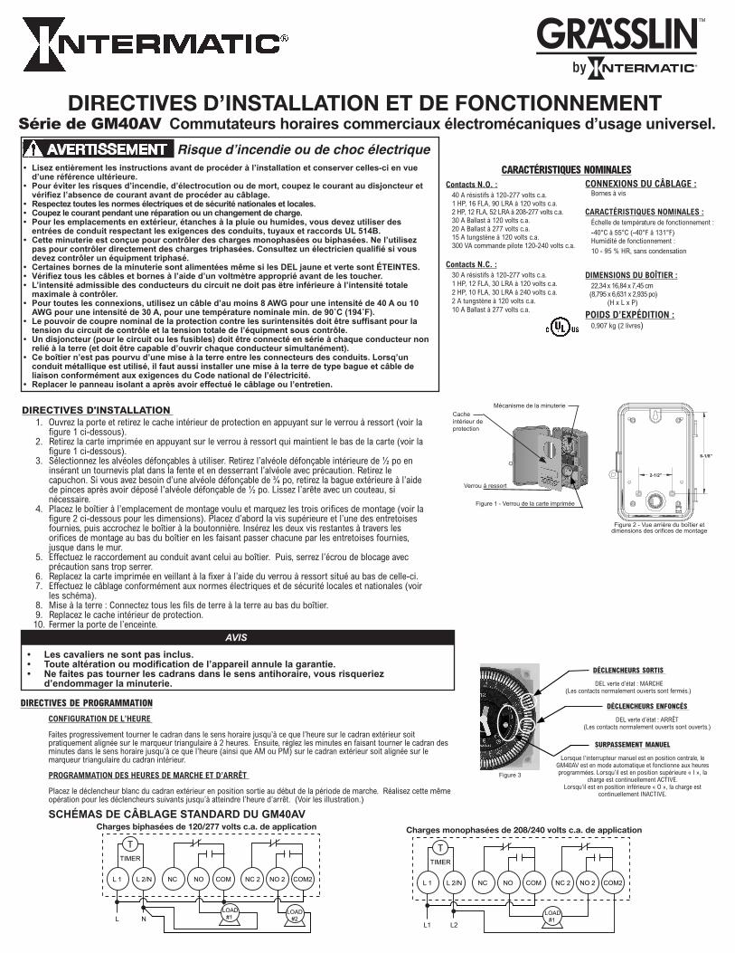
1. Ouvrez la porte et retirez le cache intérieur de protection en appuyant sur le verrou à ressort (voir la figure 1 ci-dessous). 2. Retirez la carte imprimée en appuyant sur le verrou à ressort qui maintient le bas de la carte (voir la figure 1 ci-dessous). 3. Sélectionnez les alvéoles défonçables à utiliser. Retirez l’alvéole défonçable intérieure de ½ po en insérant un tournevis plat dans la fente et en desserrant l’alvéole avec précaution. Retirez le capuchon. Si vous avez besoin d’une alvéole défonçable de ¾ po, retirez la bague extérieure à l’aide de pinces après avoir déposé l'alvéole défonçable de ½ po. Lissez l’arête avec un couteau, si nécessaire. 4. Placez le boîtier à l’emplacement de montage voulu et marquez les trois orifices de montage (voir la figure 2 ci-dessous pour les dimensions). Placez d’abord la vis supérieure et l’une des entretoises fournies, puis accrochez le boîtier à la boutonnière. Insérez les deux vis restantes à travers les orifices de montage au bas du boîtier en les faisant passer chacune par les entretoises fournies, jusque dans le mur. 5. Effectuez le raccordement au conduit avant celui au boîtier. Puis, serrez l’écrou de blocage avec précaution sans trop serrer. 6. Replacez la carte imprimée en veillant à la fixer à l’aide du verrou à ressort situé au bas de celle-ci. 7. Effectuez le câblage conformément aux normes électriques et de sécurité locales et nationales (voir les schéma). 8. Mise à la terre : Connectez tous les fils de terre à la terre au bas du boîtier. 9. Replacez le cache intérieur de protection.10. Fermer la porte de l’enceinte.
DIRECTIVES D'INSTALLATION
CONFIGURATION DE L’HEURE
Faites progressivement tourner le cadran dans le sens horaire jusqu’à ce que l’heure sur le cadran extérieur soitpratiquement alignée sur le marqueur triangulaire à 2 heures. Ensuite, réglez les minutes en faisant tourner le cadran des minutes dans le sens horaire jusqu’à ce que l’heure (ainsi que AM ou PM) sur le cadran extérieur soit alignée sur le marqueur triangulaire du cadran intérieur.
PROGRAMMATION DES HEURES DE MARCHE ET D’ARRÊT
Placez le déclencheur blanc du cadran extérieur en position sortie au début de la période de marche. Réalisez cette même opération pour les déclencheurs suivants jusqu’à atteindre l’heure d’arrêt. (Voir les illustration.)
SCHÉMAS DE CÂBLAGE STANDARD DU GM40AV
DIRECTIVES DE PROGRAMMATION
Figure 3
NO 2NC 2NONCL 2/NL 1
TTIMER
L N
COM
LOAD #1
LOAD #2
COM2 COM2NO 2NC 2NONCL 2/NL 1
TTIMER
L1 L2
COM
LOAD #1
Charges biphasées de 120/277 volts c.a. de application Charges monophasées de 208/240 volts c.a. de application
158--01124
LIMITED ONE YEAR WARRANTY
If within the warranty period specified, this product fails due to a defect in material or workmanship, Intermatic Incorporated will repair or replace it, at its sole option, free of charge. This warranty is extended to the original purchaser only and is not transferable. This warranty does not apply to: (a) damage to units caused by accident, dropping or abuse in handling, acts of God or any negligent use; (b) units which have been subject to unauthorized repair, opened, taken apart or otherwise modified; (c) units not used in accordance with instructions; (d) damages exceeding the cost of the product; (e) sealed lamps and/or lamp bulbs, LED’s and batteries; (f) the finish on any portion of the product, such as surface and/or weathering, as this is considered normal wear and tear; (g) transit damage, initial installation costs, removal costs, or reinstallation costs.
INTERMATIC INCORPORATED WILL NOT BE LIABLE FOR INCIDENTAL OR CONSEQUENTIAL DAMAGES. SOME STATES DO NOT ALLOW THE EXCLUSION OR LIMITATION OF INCIDENTAL OR CONSEQUENTIAL DAMAGES, SO THE ABOVE LIMITATION OR EXCLUSION MAY NOT APPLY TO YOU. THIS WARRANTY IS IN LIEU OF ALL OTHER EXPRESS OR IMPLIED WARRANTIES. ALL IMPLIED WARRANTIES, INCLUDING THE WARRANTY OF MERCHANTABILITY AND THE WARRANTY OF FITNESS FOR A PARTICULAR PURPOSE, ARE HEREBY MODIFIED TO EXIST ONLY AS CONTAINED IN THIS LIMITED WARRANTY, AND SHALL BE OF THE SAME DURATION AS THE WARRANTY PERIOD STATED ABOVE. SOME STATES DO NOT ALLOW LIMITATIONS ON THE DURATION OF AN IMPLIED WARRANTY, SO THE ABOVE LIMITATION MAY NOT APPLY TO YOU.
This warranty service is available by either (a) returning the product to the dealer from whom the unit was purchased, or (b) completing a warranty claim on line at www.intermatic.com. This warranty is made by: Intermatic Incorporated Customer Service/7777 Winn Rd., Spring Grove, Illinois 60081-9698 / 815-675-7000 http://www.intermatic.com
GARANTÍA LIMITADA DE UN AÑO
Si dentro del período de garantía especificado este producto falla debido a un defecto de material o de mano de obra, Intermatic Incorporated loreparará o reemplazará, a su entera discreción, sin cargo alguno. Esta garantía sólo se otorga al comprador original y no es transferible. Estagarantía no se aplica en los siguientes casos: (a) daños en las unidades causados por accidentes, caídas o manejo indebido, causas de fuerzamayor o uso negligente; (b) unidades que hayan sido sometidas a una reparación no autorizada, abiertas, desmontadas o modificadas de alguna manera; c) unidades no utilizadas de acuerdo con las instrucciones; (d) daños que excedan el costo del producto; (e) lámparas y/o bombillas de lámparas selladas, diodos emisores de luz (LED) y baterías; (f) el acabado de cualquier parte del producto, como su superficie y/o por exposición a la intemperie, ya que esto se considera un desgaste y uso normal; g) daños durante el transporte, costos de instalación inicial, costos de remoción o costos de reinstalación.
INTERMATIC INCORPORATED NO ASUME RESPONSABILIDAD ALGUNA POR DAÑOS INCIDENTALES O CONSECUENCIALES. ALGUNOS ES-TADOS NO PERMITEN EXCLUIR O LIMITAR LOS DAÑOS INCIDENTALES O CONSECUENCIALES, POR LO QUE LA LIMITACIÓN O EXCLUSIÓN ANTERIOR PUDIERA NO SER VÁLIDA EN SU CASO. ESTA GARANTÍA SUSTITUYE A CUALQUIER OTRA GARANTÍA EXPRESA O IMPLÍCITA. TODAS LAS GARANTÍAS IMPLÍCITAS, INCLUIDA LA GARANTÍA DE IDONEIDAD COMERCIAL O DE IDONEIDAD PARA UN DETERMINADO FIN, SE MODIFICAN PARA QUEDAR INCLUIDAS ÚNICAMENTE EN LA PRESENTE GARANTÍA LIMITADA, Y TENDRÁN LA MISMA DURACIÓN QUE EL PERIODO DE GARANTÍA MENCIONADO ANTES. ALGUNOS ESTADOS NO PERMITEN LIMITAR LA DURACIÓN DE UNA GARANTÍA IMPLÍCITA, POR LO QUE LA LIMITACIÓN ANTERIOR PUDIERA NO SER APLICABLE EN SU CASO.
Este servicio de garantía está disponible (a) devolviendo el producto al distribuidor donde se compró la unidad o (b) completando un reclamo de garantía en Internet en www.intermatic.com. Esta garantía es concedida por: Intermatic Incorporated Customer Service/7777 Winn Rd., Spring Grove, Illinois 60081-9698/815-675-7000 http://www.intermatic.com
INTERMATIC INCORPORATED SPRING GROVE, ILLINOIS 60081
www.Intermatic.com
GARANTIELIMITÉED’UNAN
Si, au cours de la période indiquée, ce dispositif présente une défectuosité de matériel ou de fabrication, Intermatic Incorporated s'engage à le réparer ou le remplacer, à sa seule discrétion, sans frais. Cette garantie s’applique uniquement à l’acheteur original et elle est incessible. Cette garantie ne s'applique pas : (a) aux dommages au dispositif causés par un accident, une chute ou une mauvaise manipulation, une catastrophenaturelle ou une utilisation négligente ; (b) aux dispositifs soumis à des réparations non autorisées, qui ont été ouverts, démontés ou modifiés de quelconque manière ; (c) aux dispositifs qui n'ont pas été utilisés selon les directives ; (d) aux dommages dépassant le coût du produit ; (e) aux lampes scellées et/ou aux ampoules, aux DEL et aux piles ; (f) à la finition de l'une des parties du dispositif, telle que la surface ou les caractéristiques de résistance aux intempéries, ce qui est considéré comme de l'usure normale ; (g) aux dommages causés par le transport, aux coûts d'installation initiale, aux coûts de démontage ou de remontage.
INTERMATIC INCORPORATED NE POURRA ÊTRE TENUE RESPONSABLE DE DOMMAGES ACCIDENTELS OU CONSÉCUTIFS. CERTAINS ÉTATS N'AUTORISENT PAS L'EXCLUSION OU LA LIMITATION DE DOMMAGES ACCIDENTELS OU CONSÉCUTIFS. DANS CE CAS, LES LIMITES CI-DESSUS NE S'APPLIQUENT PAS. CETTE GARANTIE REMPLACE TOUTES LES AUTRES GARANTIES EXPRESSES OU IMPLICITES. TOUTES LES GARANTIES IMPLICITES, Y COMPRIS LA GARANTIE DE COMMERCIALISATION ET LA GARANTIE DE CONFORMITÉ À UNE FIN PRÉVUE, SONT PAR LA PRÉSENTE MODIFIÉES POUR EXISTER UNIQUEMENT TELLES QUE COMPRISES DANS LA GARANTIE LIMITÉE, ET AURONT LA MÊME DURÉE QUE LA PÉRIODE DE GARANTIE DÉCLARÉE CI-DESSUS. CERTAINS ÉTATS N’ACCEPTENT PAS DE LIMITES SUR LA DURÉE D’UNE GARANTIE IMPLICITE. DANS CE CAS, LA LIMITE PEUT NE PAS VOUS CONCERNER.
Le service de garantie est disponible soit (a) par retour du produit au vendeur auprès duquel le dispositif a été acheté soit (b) en remplissant le formulaire de réclamation sur le site Web www.intermatic.com. Cette garantie est accordée par : Intermatic Incorporated / 7777 Winn Rd., Spring Grove, Illinois 60081-9698 / 815-675-7000 http://www.intermatic.com