Embed Size (px)
Citation preview
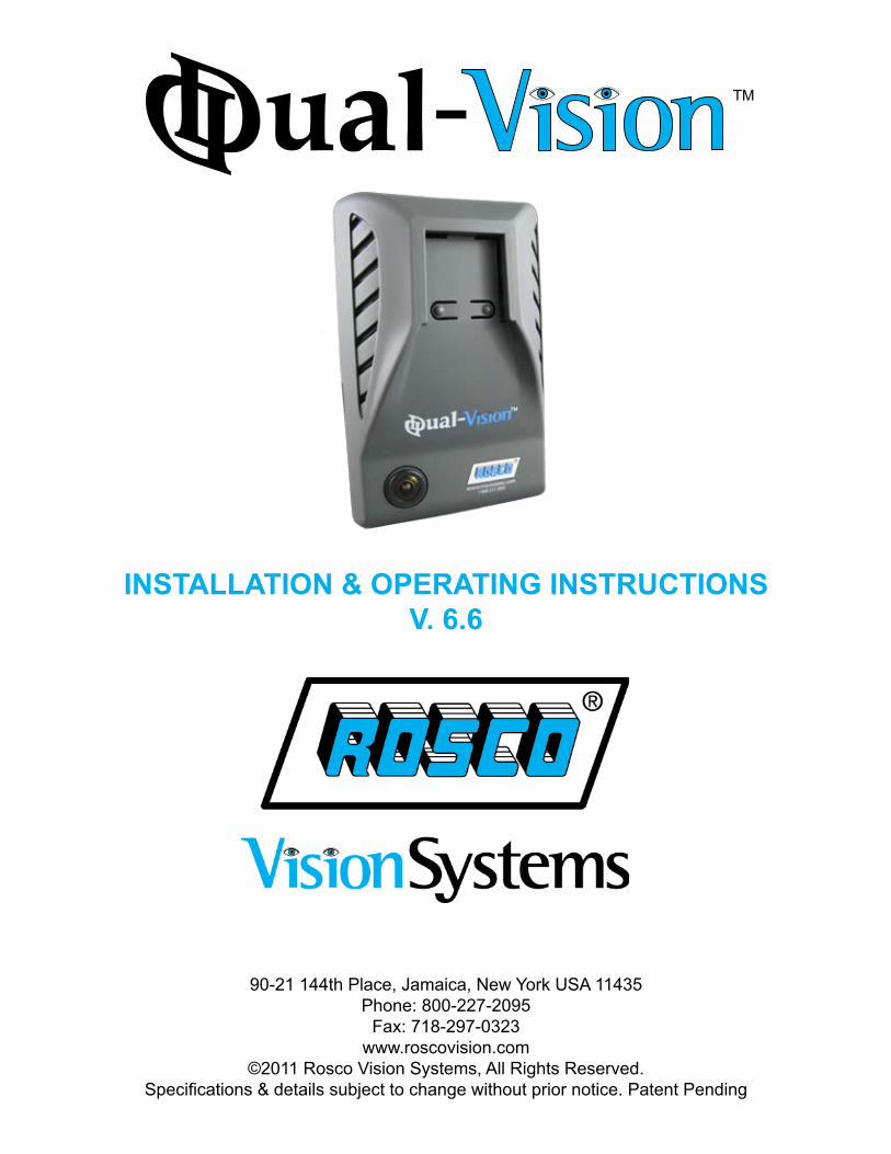
INSTALLATION & OPERATING INSTRUCTIONSV. 6.6
90-21 144th Place, Jamaica, New York USA 11435Phone: 800-227-2095
Fax: 718-297-0323www.roscovision.com
©2011 Rosco Vision Systems, All Rights Reserved.Specifications & details subject to change without prior notice. Patent Pending
Table Of Contents
Safety Instructions........................................................................................................ 1Introduction / Options.................................................................................................... 2Components.................................................................................................................. 3Parts Nomenclature...................................................................................................... 5Technical Specifications............................................................................................... 7
IMPORTANT - Read Before Using Product............................................................... 8 SD Card............................................................................................................... 8 Dual-Vision™ Functions...................................................................................... 9 32G Firmware Update Guide *MUST BE PERFORMED*.................................... 10 Dual-Vision™ Firmware & Reader Update............................................................ 11 System Configuration *MUST BE PERFORMED*.............................................. 12 Continuous Recording While Driving................................................................... 14
Basic Installation......................................................................................................... 15 Installing The Remote Manual Alarm Event Button.............................................. 17
Dual-Vision™ Player................................................................................................... 18 Review Video....................................................................................................... 18 Playback Interface Controls................................................................................. 19 Volume & Playback Speed Controls..................................................................... 20 Detailed Video Playback Instructions................................................................... 20 Converting files to AVI file format.......................................................................... 21 Interfacing with a Google Maps............................................................................ 22 Additional Software Playback Functions.............................................................. 23 Analyzing G-Sensor Data..................................................................................... 24 System Diagnostics Display Codes...................................................................... 25
Troubleshooting.......................................................................................................... 26
Installation of Power/Delay Timer Module DV138................................................ 27 Components........................................................................................................ 27 Main Features...................................................................................................... 27 Installation Instructions........................................................................................ 27
Installation of Security Enclosure DV106................................................................. 28
Copyright Rosco, Inc. ©2011 - All Rights Reserved
CAUTION - Read This Entire Manual Before Installation
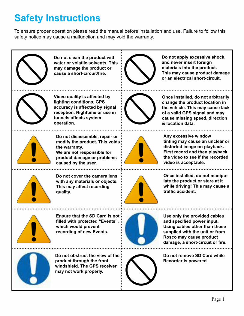
Safety InstructionsTo ensure proper operation please read the manual before installation and use. Failure to follow this safety notice may cause a malfunction and may void the warranty.
Do not clean the product with water or volatile solvents. This may damage the product or cause a short-circuit/fire.
Video quality is affected by lighting conditions, GPSaccuracy is affected by signal reception. Nighttime or use in tunnels affects systemoperation.
Do not apply excessive shock, and never insert foreignmaterials into the product.This may cause product damage or an electrical short-circuit.
Once installed, do not arbitrarily change the product location in the vehicle. This may cause lack of a valid GPS signal and may cause missing speed, direction & location data.
Do not disassemble, repair or modify the product. This voids the warranty.We are not responsible for product damage or problems caused by the user.
Do not cover the camera lens with any materials or objects. This may affect recordingquality.
Ensure that the SD Card is not filled with protected “Events”, which would preventrecording of new Events.
Any excessive windowtinting may cause an unclear or distorted image on playback. First record and then playback the video to see if the recorded video is acceptable.
Once installed, do not manipu-late the product or stare at it while driving! This may cause a traffic accident.
Use only the provided cables and specified power input. Using cables other than those supplied with the unit or from Rosco may cause productdamage, a short-circuit or fire.
Do not obstruct the view of the product through the frontwindshield. The GPS receiver may not work properly.
Do not remove SD Card while Recorder is powered.
Page 1
IntroductionRosco’s Dual-Vision™ System allows recording of vehicle travel data and exterior/interior video. Mounted on the windshield, Dual-Vision’s™ twin cameras capture wide-angle views of the forward exterior field of vision as well as the driver/passenger compartment. Privacy concerns may be addressed through several means, including disabling of interior audio recording. Data is recorded in a continuous loop, with oldest data erased by more recent video, however the compact system can hold up to 30 hours of data before any overwriting takes place. For protection of important events, the system is programmed to mark certain occurrences, such as driver-initiated markings or excessive G-Force, and prevent them from being overwritten. An internal GPS antenna enables recording of vehicle location, speed, and direction.
All the data is stored in proprietary files located on a removable SD card. Video, audio, location information, and G-force data may only be reviewed by viewing the contents of the SD card using proprietary Player software on any Windows PC. The software is provided at no additional cost to the end-user, and there are no follow-up fees for use or updating of the Player by authorized users. Once viewed, the data may be deleted or stored at the manager’s discretion. Critical videos may be converted to standard media-player formats for transmission to legal or administrative offices.
Page 2
OptionsThe Dual-Vision™ may be used in a variety of applications, and there are several accessories available in order to tailor the application to the end-user. Installation may be as simple as mounting the unit on a vehicle’s windshield and providing power through a cigarette-lighter cord. Commercial grade installations may be accomplished using optional Security Enclosures to prevent the unauthorized removal of the SD card. High quality installations may require hard-wire setups into a commercial vehicle’s electrical system to discourage tampering and provide recording capability even after the engine has been shut off. Additionally, there are several infra-red modules available to enhance night-vision within the driver/passenger compartment.
Optional DV-Pro™ Fleet Management SoftwareDual-Vision™ kits are complete with our standard Dual-Vision™ Player software. For more advanced needs, Rosco has developed DV-Pro™ an exclusive fleet management software system for managing multi-vehicle video recordings and data. Use the software to archive footage by driver, vehicle, or to insert descriptive tags highlighting video segments of interest. Post-route GPS tracker data is easily accessed to help evaluate location, routing, and speed. The software creates Excel spreadsheets for driver safety and exception reports for Events. There are no monthly/annual fees or setup costs associ-ated with DV-Pro™. Contact Rosco or your authorized dealer for more information.
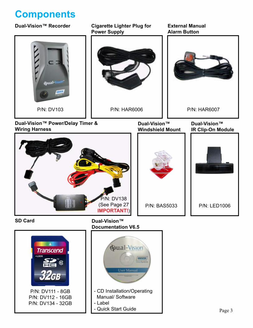
ComponentsDual-Vision™ Recorder
P/N: DV103
P/N: DV111 - 8GBP/N: DV112 - 16GBP/N: DV134 - 32GB
P/N: BAS5033 P/N: LED1006
P/N: HAR6006
- CD Installation/Operating Manual/ Software- Label- Quick Start Guide
P/N: HAR6007
SD Card
Dual-Vision™ Power/Delay Timer &Wiring Harness
Cigarette Lighter Plug for Power Supply
Dual-Vision™Documentation V6.5
Dual-Vision™Windshield Mount
Dual-Vision™IR Clip-On Module
External ManualAlarm Button
Page 3
P/N: DV138(See Page 27IMPORTANT!)
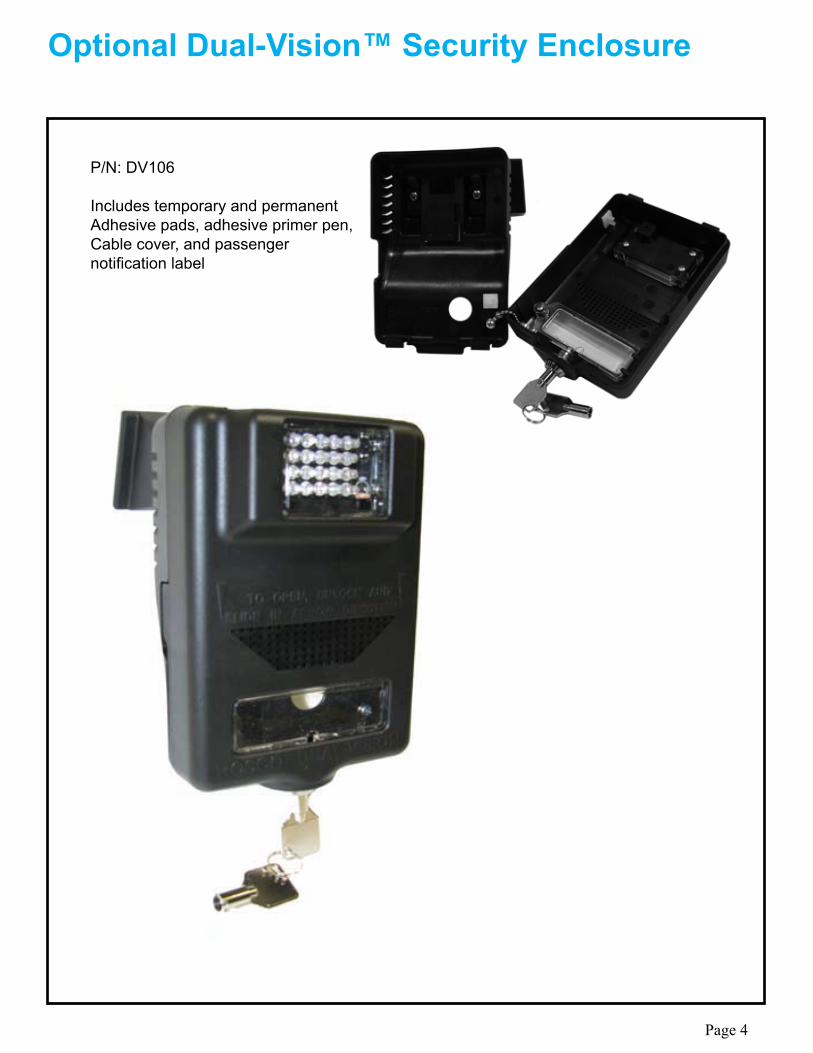
Optional Dual-Vision™ Security Enclosure
P/N: DV106
Includes temporary and permanentAdhesive pads, adhesive primer pen,Cable cover, and passengernotification label
Page 4
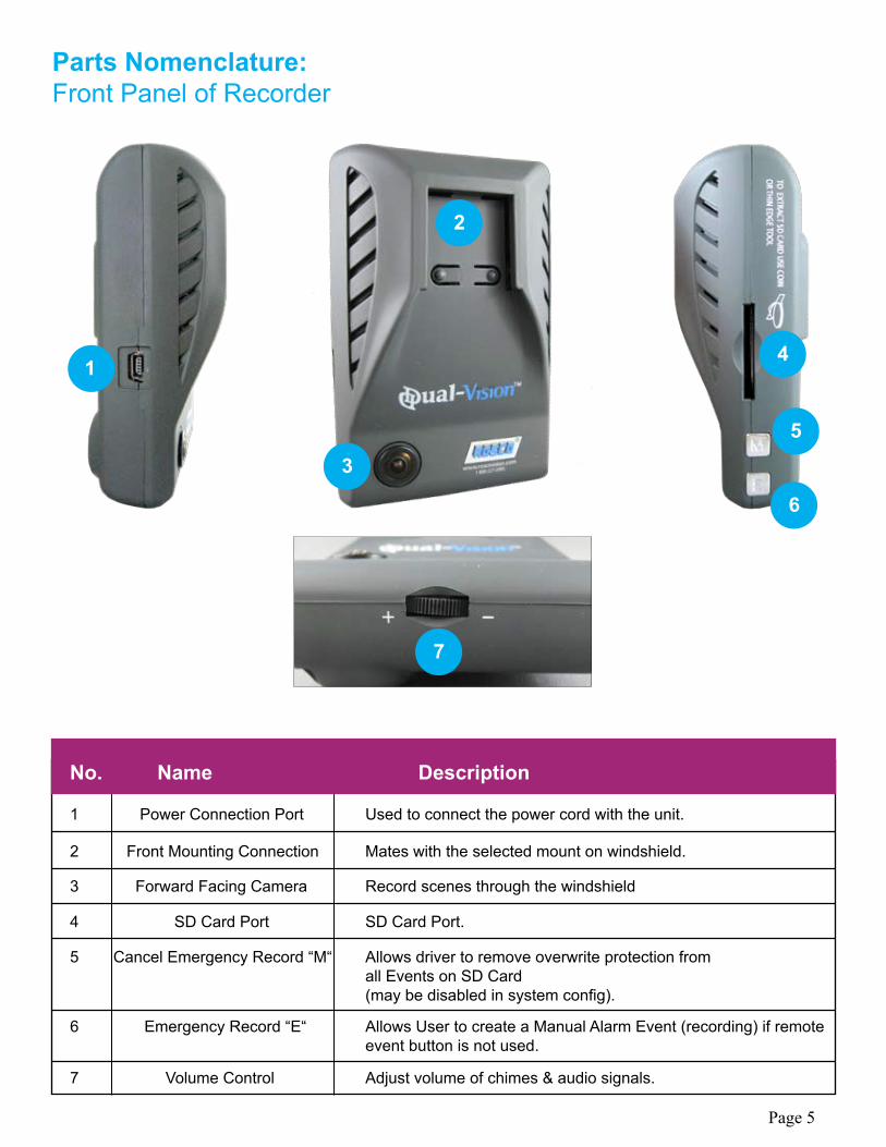
Parts Nomenclature:Front Panel of Recorder
No. Name Description
1 Power Connection Port Used to connect the power cord with the unit.
2 Front Mounting Connection Mates with the selected mount on windshield.
3 Forward Facing Camera Record scenes through the windshield
4 SD Card Port SD Card Port.
5 Cancel Emergency Record “M“ Allows driver to remove overwrite protection from all Events on SD Card (may be disabled in system config).
6 Emergency Record “E“ Allows User to create a Manual Alarm Event (recording) if remote event button is not used.
7 Volume Control Adjust volume of chimes & audio signals.
1
2
3
4
5
6
7
Page 5
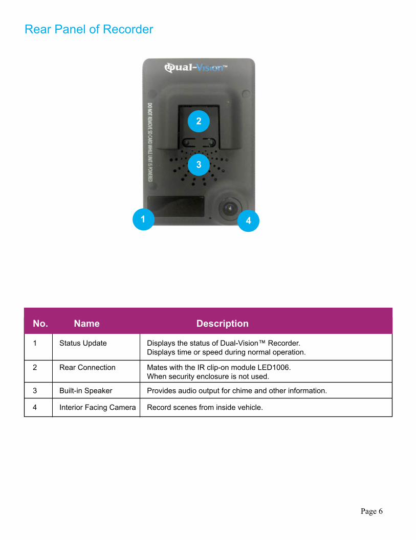
Rear Panel of Recorder
No. Name Description
1 Status Update Displays the status of Dual-Vision™ Recorder. Displays time or speed during normal operation.
2 Rear Connection Mates with the IR clip-on module LED1006. When security enclosure is not used.
3 Built-in Speaker Provides audio output for chime and other information.
4 Interior Facing Camera Record scenes from inside vehicle.
1
2
3
4
Page 6
Item Specification
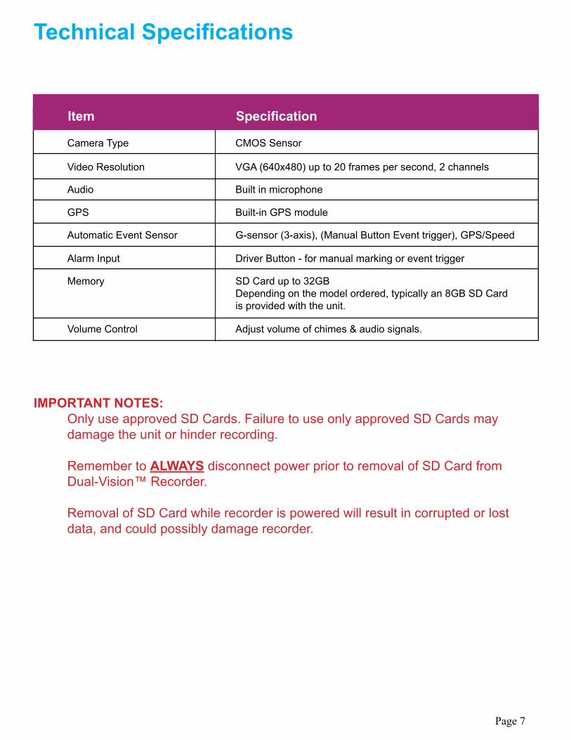
Camera Type CMOS Sensor
Video Resolution VGA (640x480) up to 20 frames per second, 2 channels
Audio Built in microphone
GPS Built-in GPS module
Automatic Event Sensor G-sensor (3-axis), (Manual Button Event trigger), GPS/Speed
Alarm Input Driver Button - for manual marking or event trigger
Memory SD Card up to 32GB Depending on the model ordered, typically an 8GB SD Card is provided with the unit.
Volume Control Adjust volume of chimes & audio signals.
Technical Specifications
IMPORTANT NOTES: Only use approved SD Cards. Failure to use only approved SD Cards may damage the unit or hinder recording.
Remember to ALWAYS disconnect power prior to removal of SD Card from Dual-Vision™ Recorder.
Removal of SD Card while recorder is powered will result in corrupted or lost data, and could possibly damage recorder.
Page 7
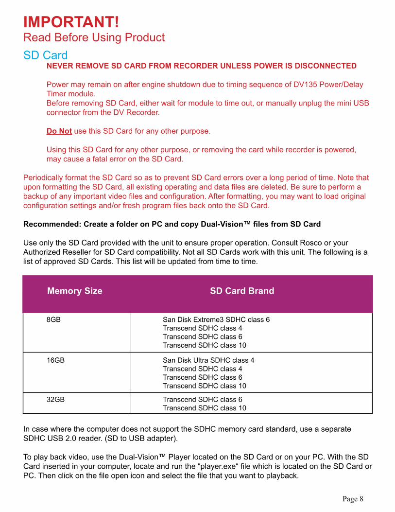
IMPORTANT!Read Before Using ProductSD Card NEVER REMOVE SD CARD FROM RECORDER UNLESS POWER IS DISCONNECTED
Power may remain on after engine shutdown due to timing sequence of DV135 Power/Delay Timer module. Before removing SD Card, either wait for module to time out, or manually unplug the mini USB connector from the DV Recorder.
Do Not use this SD Card for any other purpose.
Using this SD Card for any other purpose, or removing the card while recorder is powered, may cause a fatal error on the SD Card.
Periodically format the SD Card so as to prevent SD Card errors over a long period of time. Note that upon formatting the SD Card, all existing operating and data files are deleted. Be sure to perform a backup of any important video files and configuration. After formatting, you may want to load original configuration settings and/or fresh program files back onto the SD Card.
Recommended: Create a folder on PC and copy Dual-Vision™ files from SD Card
Use only the SD Card provided with the unit to ensure proper operation. Consult Rosco or yourAuthorized Reseller for SD Card compatibility. Not all SD Cards work with this unit. The following is a list of approved SD Cards. This list will be updated from time to time.
In case where the computer does not support the SDHC memory card standard, use a separate SDHC USB 2.0 reader. (SD to USB adapter).
To play back video, use the Dual-Vision™ Player located on the SD Card or on your PC. With the SD Card inserted in your computer, locate and run the “player.exe“ file which is located on the SD Card or PC. Then click on the file open icon and select the file that you want to playback.
Page 8
Memory Size SD Card Brand
8GB San Disk Extreme3 SDHC class 6 Transcend SDHC class 4 Transcend SDHC class 6 Transcend SDHC class 10
16GB San Disk Ultra SDHC class 4 Transcend SDHC class 4 Transcend SDHC class 6 Transcend SDHC class 10
32GB Transcend SDHC class 6 Transcend SDHC class 10
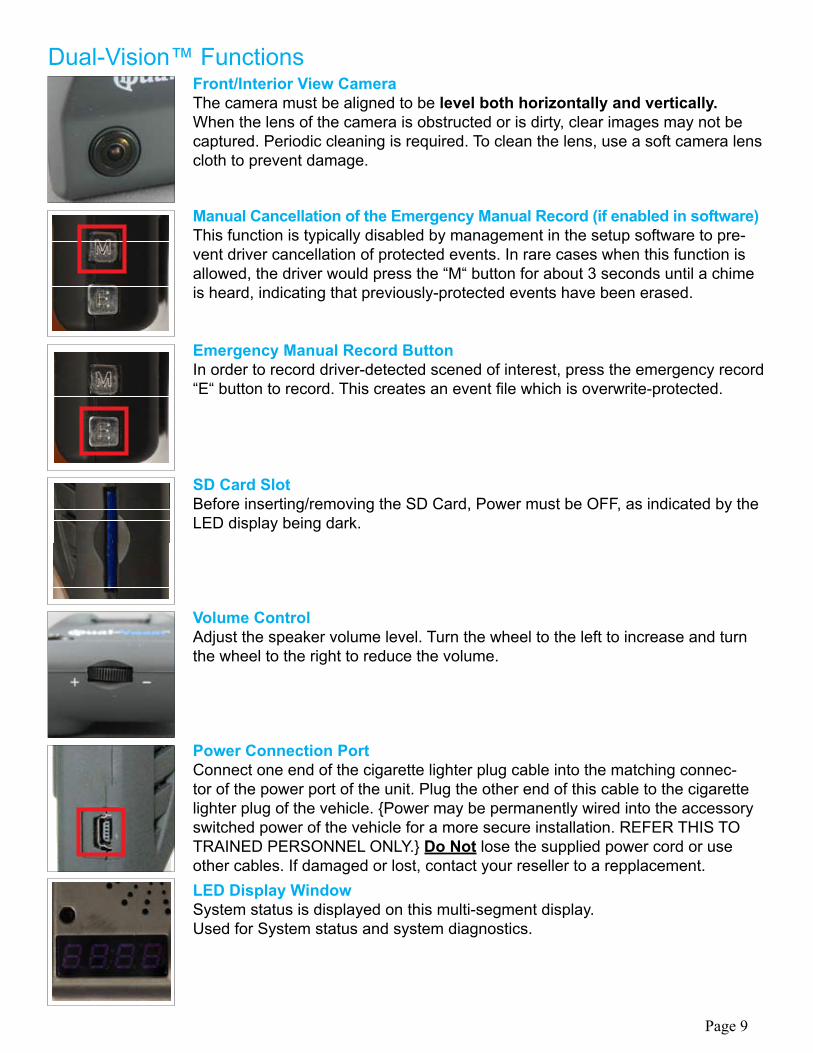
Dual-Vision™ FunctionsFront/Interior View CameraThe camera must be aligned to be level both horizontally and vertically.When the lens of the camera is obstructed or is dirty, clear images may not be captured. Periodic cleaning is required. To clean the lens, use a soft camera lens cloth to prevent damage.
Manual Cancellation of the Emergency Manual Record (if enabled in software)This function is typically disabled by management in the setup software to pre-vent driver cancellation of protected events. In rare cases when this function is allowed, the driver would press the “M“ button for about 3 seconds until a chime is heard, indicating that previously-protected events have been erased.
Emergency Manual Record ButtonIn order to record driver-detected scened of interest, press the emergency record “E“ button to record. This creates an event file which is overwrite-protected.
SD Card SlotBefore inserting/removing the SD Card, Power must be OFF, as indicated by the LED display being dark.
Volume ControlAdjust the speaker volume level. Turn the wheel to the left to increase and turn the wheel to the right to reduce the volume.
Power Connection PortConnect one end of the cigarette lighter plug cable into the matching connec-tor of the power port of the unit. Plug the other end of this cable to the cigarette lighter plug of the vehicle. {Power may be permanently wired into the accessory switched power of the vehicle for a more secure installation. REFER THIS TO TRAINED PERSONNEL ONLY.} Do Not lose the supplied power cord or use other cables. If damaged or lost, contact your reseller to a repplacement.LED Display WindowSystem status is displayed on this multi-segment display.Used for System status and system diagnostics.
Page 9
IMPORTANT!Read Before Using Product
32G Firmware Update GuideNOTICE: Dual-Vision™ is now capable of operating with SD Cards of up to 32GB
When transitioning to 32GB capability it is required to have the following in order to properly play and view files:
Firmware Version 2.73 or higherPlayer Version 2.0.0.2 or higherDV-Pro Version 2.2 or higher(Optional)
Please update your DV Recorder with the latest firmware and GPS data. Follow the instructions on the following pages. For Rosco’s exclusive fleet management software DV-Pro, customers should update to DV-Pro version 2.2. For more information on DV-Pro please contact your local salesrepresentative or go online to http://www.roscovision.com/.
Note: Events recorded with 32GB firmware version 2.73 will not show correct event logging on Player versions 2.0.0.0 and older. Events recorded with earlier Dual-Vision™ firmware versions 2.65 and earlier will not be correctly logged on Player 2.0.0.2. It is recommended that thecorrect version of Player be kept on the desktop.
DV-Pro Version 2.2 is backwards compatible with non-32GB Firmware Versions. However olderversions of DV-Pro cannot correctly identify event markings on newly recorded files.
Page 10
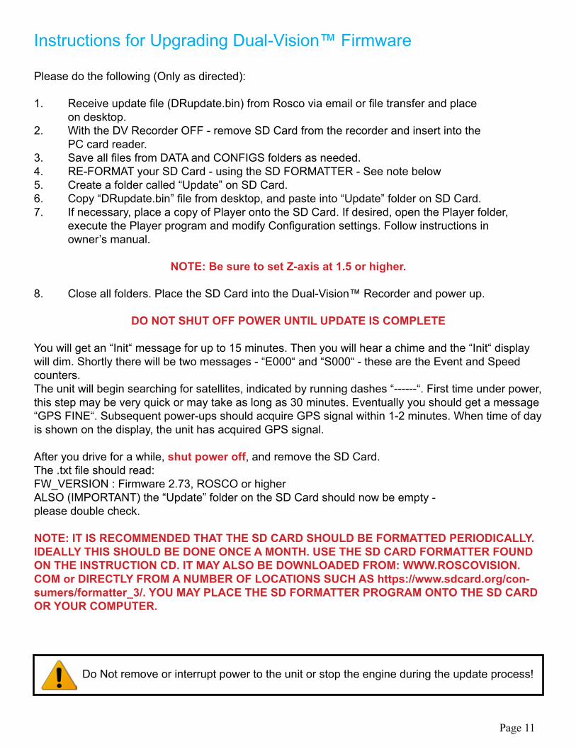
Instructions for Upgrading Dual-Vision™ Firmware
Please do the following (Only as directed): 1. Receive update file (DRupdate.bin) from Rosco via email or file transfer and place on desktop. 2. With the DV Recorder OFF - remove SD Card from the recorder and insert into the PC card reader.3. Save all files from DATA and CONFIGS folders as needed.4. RE-FORMAT your SD Card - using the SD FORMATTER - See note below5. Create a folder called “Update” on SD Card.6. Copy “DRupdate.bin” file from desktop, and paste into “Update” folder on SD Card.7. If necessary, place a copy of Player onto the SD Card. If desired, open the Player folder, execute the Player program and modify Configuration settings. Follow instructions in owner’s manual.
NOTE: Be sure to set Z-axis at 1.5 or higher.
8. Close all folders. Place the SD Card into the Dual-Vision™ Recorder and power up.
DO NOT SHUT OFF POWER UNTIL UPDATE IS COMPLETE
You will get an “Init“ message for up to 15 minutes. Then you will hear a chime and the “Init“ display will dim. Shortly there will be two messages - “E000“ and “S000“ - these are the Event and Speed counters.The unit will begin searching for satellites, indicated by running dashes “------“. First time under power, this step may be very quick or may take as long as 30 minutes. Eventually you should get a message “GPS FINE“. Subsequent power-ups should acquire GPS signal within 1-2 minutes. When time of day is shown on the display, the unit has acquired GPS signal.
After you drive for a while, shut power off, and remove the SD Card.The .txt file should read:FW_VERSION : Firmware 2.73, ROSCO or higherALSO (IMPORTANT) the “Update” folder on the SD Card should now be empty -please double check.
NOTE: IT IS RECOMMENDED THAT THE SD CARD SHOULD BE FORMATTED PERIODICALLY. IDEALLY THIS SHOULD BE DONE ONCE A MONTH. USE THE SD CARD FORMATTER FOUND ON THE INSTRUCTION CD. IT MAY ALSO BE DOWNLOADED FROM: WWW.ROSCOVISION.COM or DIRECTLY FROM A NUMBER OF LOCATIONS SUCH AS https://www.sdcard.org/con-sumers/formatter_3/. YOU MAY PLACE THE SD FORMATTER PROGRAM ONTO THE SD CARD OR YOUR COMPUTER.
Do Not remove or interrupt power to the unit or stop the engine during the update process!
Page 11
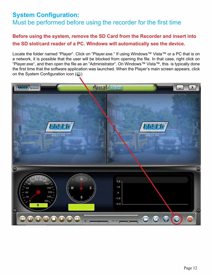
System Configuration:Must be performed before using the recorder for the first time Before using the system, remove the SD Card from the Recorder and insert into the SD slot/card reader of a PC. Windows will automatically see the device. Locate the folder named “Player“. Click on “Player.exe.“ If using Windows™ Vista™ or a PC that is on a network, it is possible that the user will be blocked from opening the file. In that case, right click on “Player.exe“, and then open the file as an “Administrator“. On Windows™ Vista™, this is typically done the first time that the software application was launched. When the Player’s main screen appears, click on the System Configuration icon ( )
Page 12
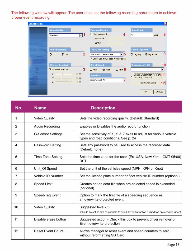
The following window will appear. The user must set the following recording parameters to achieve proper event recording:
No. Name Description
1 Video Quality Sets the video recording quality. (Default: Standard)
2 Audio Recording Enables or Disables the audio record function
3 G-Sensor Settings Set the sensitivity of X, Y, & Z axes to adjust for various vehicle types and road conditions. See p. 24
4 Password Setting Sets any password to be used to access the recorded data. (Default: none)
5 Time Zone Setting Sets the time zone for the user. (Ex. USA, New York - GMT-05:00) DST
6 Unit_Of Speed Set the unit of the vehicles speed (MPH, KPH or Knot)
7 Vehicle ID Number Set the license plate number or fleet vehicle ID number (optional)
8 Speed Limit Creates not on data file when pre-selected speed is exceeded (optional)
9 Speed/Tag Event Option to mark the first file of a speeding sequence as an overwrite-protected event
10 Video Quality Suggested level - 3 (Should be set as dim as possible to avoid driver distraction & shadows on recorded video)
11 Disable erase button Suggested action - Check this box to prevent driver removal of Event overwrite protection
12 Reset Event Count Allows manager to reset event and speed counters to zero without reformatting SD Card
1 4
5
6
7
8
9
10
11
12
2
3
Page 13
Preparation For Video Recording1. After configuring the system, re-insert the SD Card in the recorder, and install recorder in the vehicle. Follow the installation instructions. When you connect the unit to power, or turn the engine on, “Init“ will appear on the LED display indicating that the recorder is initializing. Approximately one minute after powering on, the unit should complete initializing and a “ding-dong“ chime will sound. Recording begins at this time, although GPS data may not yet be active.
2. LCD Display Window will indicate the number G-force or Driver-Button Events recorded since last reset. This alphanumerical code (E000) will remain displayed for 10 seconds. Next, a similar display (S000) will indicate the number of times that speed limit was exceeded.
3. The LED Display Window will show four dashes (----), indicating that GPS satellites are being acquired. This may take a while; up to 30 minutes on initial startup, 1-3 minutes on subsequent vehicle starts. When “GPS FINE“, time or speed value appears in the display, this indicates that GPS data is now being embedded into the recording.
4. After the acquisition of signal, the Dual-Vision™ recorder starts continuous recording with GPS data. The unit is recording video and audio (optional) as well as vehicle speed, direction and location.
NOTE: When the vehicle is in motion, the LCD displays vehicle speed. When the vehicle is stopped, the LCD displays local time.
Continuous Recording While Driving
1. When the capacity of the SD Card has been reached, the oldest files are overwritten for continuous recording. “Event“ data recorded by either the unit’s internal G-Sensor or external manual button are not overwritten.
2. After power to Dual-Vision™ recorder is disconnected, Dual-Vision™ unit stays on for an additional 5 seconds.
3. For continuous recording after engine shutdown (timed delay shutdown recording), discard the cigarette lighter and use the Delay Timer Module, DV138, and follow wiring instructions located in the back of this manual.
4. For tamper-resistant, secure installation, consider using the Security Enclosure, P/N: DV106, described in the back of this manual.
Be sure to stop the engine before installing the product. Remove all power to any areas where wires will be connected. Install the product in a location where the satellite signals may be properly received. (We recommend testing for GPS acquisition prior to permanent mounting) Before permanently mounting the unit, ensure that the camera views meet your requirements. (ex: where the interior view is not hidden by the interior mirror.) The Recorder must be aligned both horizontally and vertically.
Page 14
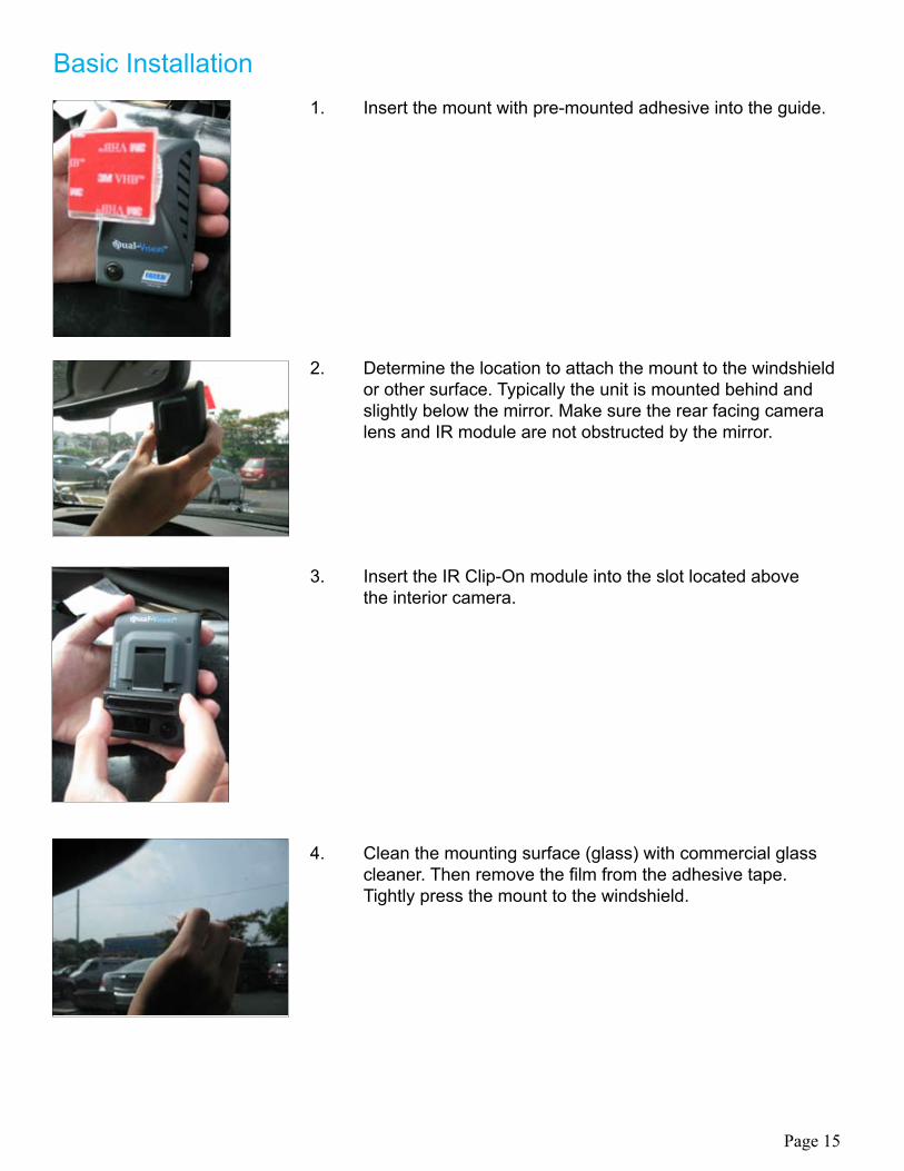
Basic Installation1. Insert the mount with pre-mounted adhesive into the guide.
3. Insert the IR Clip-On module into the slot located above the interior camera.
4. Clean the mounting surface (glass) with commercial glass cleaner. Then remove the film from the adhesive tape. Tightly press the mount to the windshield.
2. Determine the location to attach the mount to the windshield or other surface. Typically the unit is mounted behind and slightly below the mirror. Make sure the rear facing camera lens and IR module are not obstructed by the mirror.
Page 15
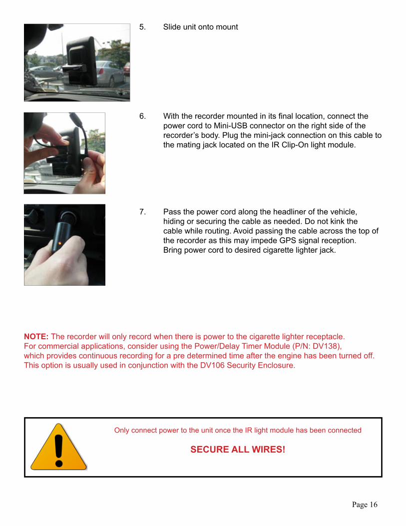
5. Slide unit onto mount
Only connect power to the unit once the IR light module has been connected
SECURE ALL WIRES!
6. With the recorder mounted in its final location, connect the power cord to Mini-USB connector on the right side of the recorder’s body. Plug the mini-jack connection on this cable to the mating jack located on the IR Clip-On light module.
7. Pass the power cord along the headliner of the vehicle, hiding or securing the cable as needed. Do not kink the cable while routing. Avoid passing the cable across the top of the recorder as this may impede GPS signal reception. Bring power cord to desired cigarette lighter jack.
NOTE: The recorder will only record when there is power to the cigarette lighter receptacle.For commercial applications, consider using the Power/Delay Timer Module (P/N: DV138),which provides continuous recording for a pre determined time after the engine has been turned off. This option is usually used in conjunction with the DV106 Security Enclosure.
Page 16
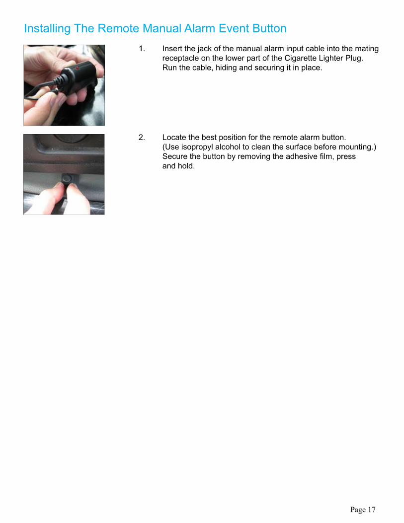
Installing The Remote Manual Alarm Event Button1. Insert the jack of the manual alarm input cable into the mating receptacle on the lower part of the Cigarette Lighter Plug. Run the cable, hiding and securing it in place.
2. Locate the best position for the remote alarm button. (Use isopropyl alcohol to clean the surface before mounting.) Secure the button by removing the adhesive film, press and hold.
Page 17
Component Requirement
CPU Pentium 4 / 1GHz processor or higher
PC Minimum System Requirements:
Memory 512 MB of RAM or higher
Operating System Microsoft Windows XP Home Edition or higher
Graphics DirectX 8.1b or higher
Hard disk drive space 200 MB or higher
Dual-Vision™ Player
*Note: when using MS Windows Vista and the Dual-Vision™ Player software for the first time, you may have to run the Player in Administrator Mode. Dual-Vision™ Player software is not compatible with Mac OS.
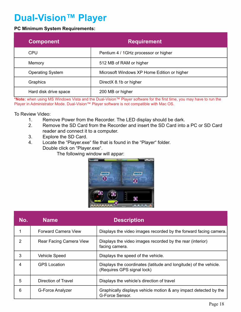
To Review Video: 1. Remove Power from the Recorder. The LED display should be dark. 2. Remove the SD Card from the Recorder and insert the SD Card into a PC or SD Card reader and connect it to a computer. 3. Explore the SD Card. 4. Locate the “Player.exe“ file that is found in the “Player“ folder. Double click on “Player.exe“. The following window will appar:
No. Name Description
1 Forward Camera View Displays the video images recorded by the forward facing camera.
2 Rear Facing Camera View Displays the video images recorded by the rear (interior) facing camera.
3 Vehicle Speed Displays the speed of the vehicle.
4 GPS Location Displays the coordinates (latitude and longitude) of the vehicle. (Requires GPS signal lock)
5 Direction of Travel Displays the vehicle’s direction of travel
6 G-Force Analyzer Graphically displays vehicle motion & any impact detected by the G-Force Sensor.
Page 18
Btn. Function Btn. Function
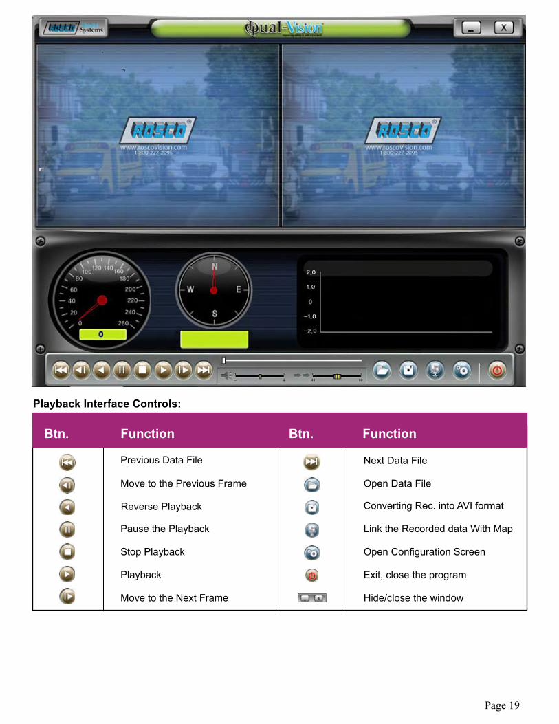
Previous Data File Next Data File
Move to the Previous Frame Open Data File
Reverse Playback Converting Rec. into AVI format
Pause the Playback Link the Recorded data With Map
Stop Playback Open Configuration Screen
Playback Exit, close the program
Move to the Next Frame Hide/close the window
Playback Interface Controls:
Page 19
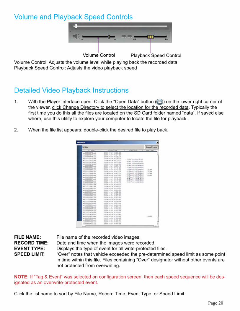
Volume and Playback Speed Controls
Detailed Video Playback Instructions
Volume Control: Adjusts the volume level while playing back the recorded data.Playback Speed Control: Adjusts the video playback speed
1. With the Player interface open: Click the “Open Data“ button ( ) on the lower right corner of the viewer, click Change Directory to select the location for the recorded data. Typically the first time you do this all the files are located on the SD Card folder named “data“. If saved else where, use this utility to explore your computer to locate the file for playback.
2. When the file list appears, double-click the desired file to play back.
FILE NAME: File name of the recorded video images.RECORD TIME: Date and time when the images were recorded.EVENT TYPE: Displays the type of event for all write-protected files.SPEED LIMIT: “Over“ notes that vehicle exceeded the pre-determined speed limit as some point in time within this file. Files containing “Over“ designator without other events are not protected from overwriting.
NOTE: If “Tag & Event“ was selected on configuration screen, then each speed sequence will be des-ignated as an overwrite-protected event.
Click the list name to sort by File Name, Record Time, Event Type, or Speed Limit.
Volume Control Playback Speed Control
Page 20
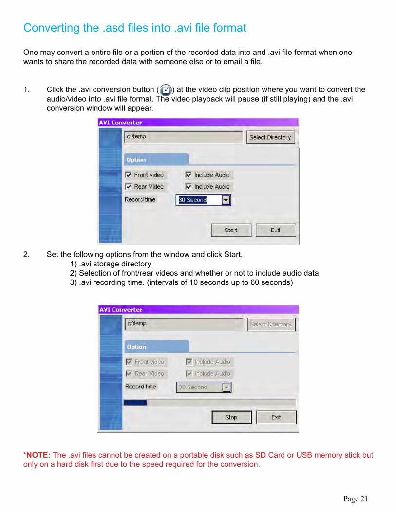
Converting the .asd files into .avi file format
One may convert a entire file or a portion of the recorded data into and .avi file format when one wants to share the recorded data with someone else or to email a file.
1. Click the .avi conversion button ( ) at the video clip position where you want to convert the audio/video into .avi file format. The video playback will pause (if still playing) and the .avi conversion window will appear.
2. Set the following options from the window and click Start. 1) .avi storage directory 2) Selection of front/rear videos and whether or not to include audio data 3) .avi recording time. (intervals of 10 seconds up to 60 seconds)
*NOTE: The .avi files cannot be created on a portable disk such as SD Card or USB memory stick but only on a hard disk first due to the speed required for the conversion.
Page 21
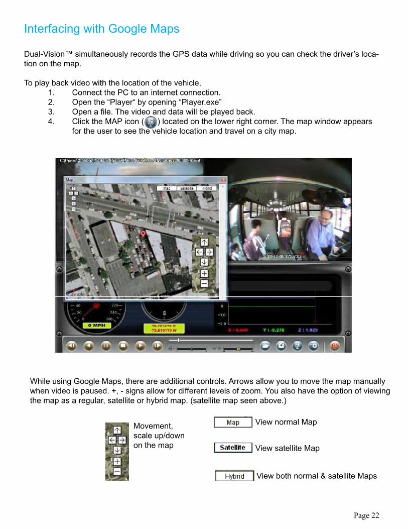
Interfacing with Google Maps
Dual-Vision ™ simultaneously records the GPS data while driving so you can check the driver’s loca-tion on the map.
To play back video with the location of the vehicle, 1. Connect the PC to an internet connection. 2. Open the “Player“ by opening “Player.exe” 3. Open a file. The video and data will be played back. 4. Click the MAP icon ( ) located on the lower right corner. The map window appears for the user to see the vehicle location and travel on a city map.
While using Google Maps, there are additional controls. Arrows allow you to move the map manually when video is paused. +, - signs allow for different levels of zoom. You also have the option of viewing the map as a regular, satellite or hybrid map. (satellite map seen above.)
Movement,scale up/downon the map
View normal Map
View satellite Map
View both normal & satellite Maps
Page 22
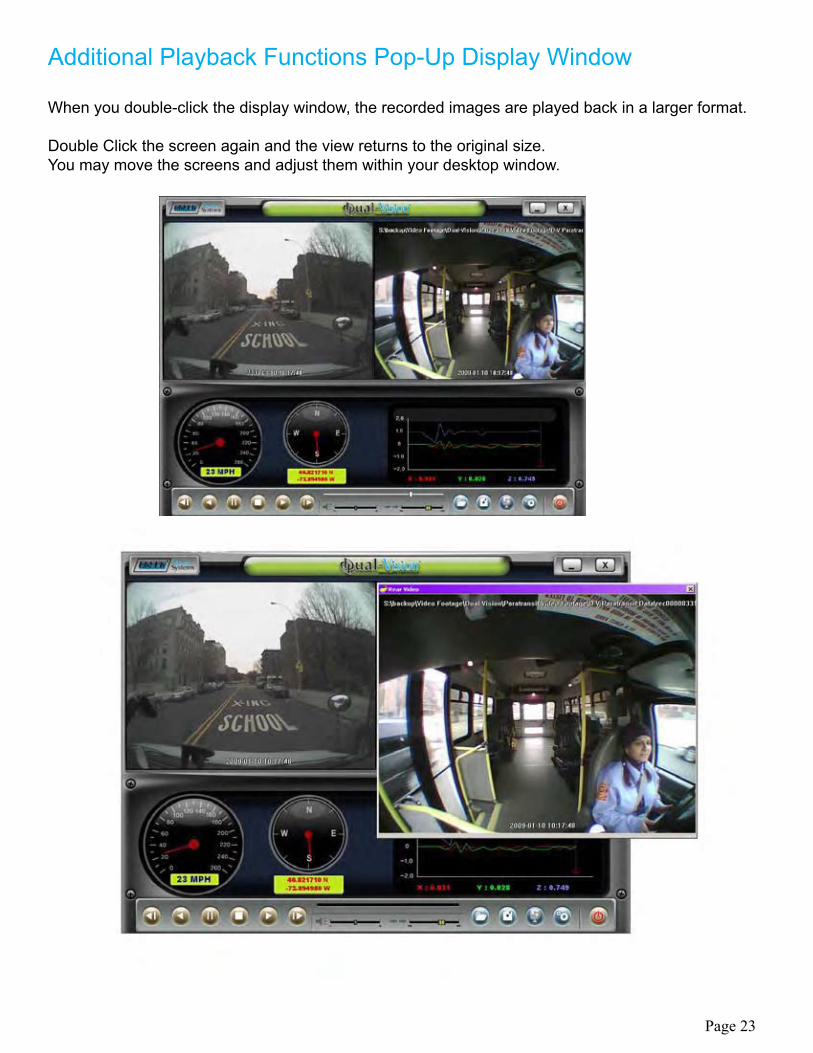
Additional Playback Functions Pop-Up Display Window
When you double-click the display window, the recorded images are played back in a larger format.
Double Click the screen again and the view returns to the original size.You may move the screens and adjust them within your desktop window.
Page 23
Setting Up & Analyzing G-SENSOR Data
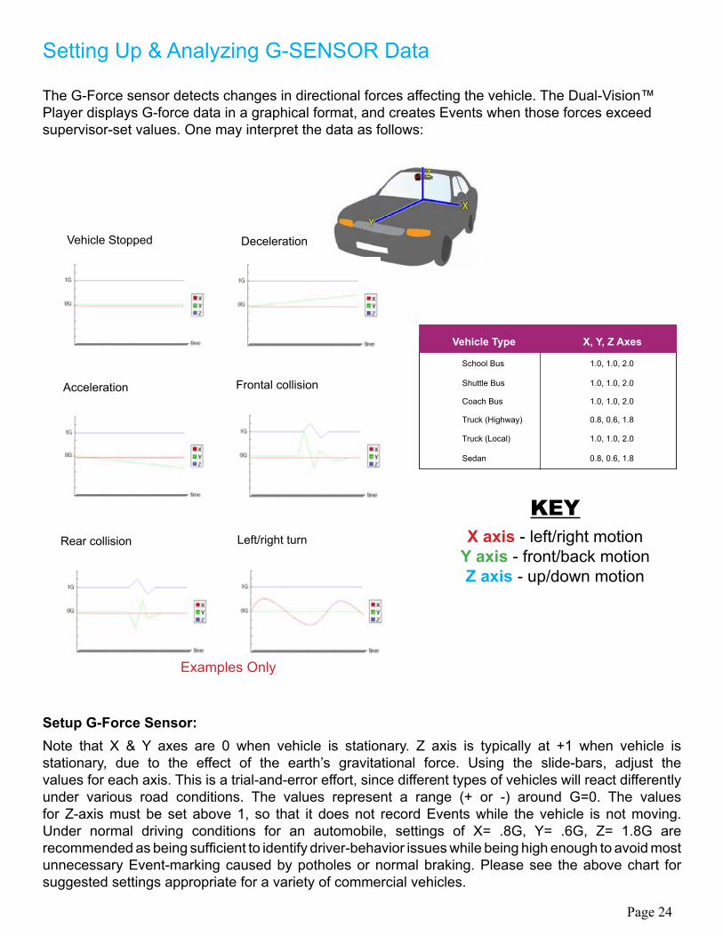
The G-Force sensor detects changes in directional forces affecting the vehicle. The Dual-Vision™ Player displays G-force data in a graphical format, and creates Events when those forces exceed supervisor-set values. One may interpret the data as follows:
Note that X & Y axes are 0 when vehicle is stationary. Z axis is typically at +1 when vehicle is stationary, due to the effect of the earth’s gravitational force. Using the slide-bars, adjust the values for each axis. This is a trial-and-error effort, since different types of vehicles will react differently under various road conditions. The values represent a range (+ or -) around G=0. The values for Z-axis must be set above 1, so that it does not record Events while the vehicle is not moving. Under normal driving conditions for an automobile, settings of X= .8G, Y= .6G, Z= 1.8G are recommended as being sufficient to identify driver-behavior issues while being high enough to avoid most unnecessary Event-marking caused by potholes or normal braking. Please see the above chart for suggested settings appropriate for a variety of commercial vehicles.
Vehicle Type X, Y, Z Axes
School Bus 1.0, 1.0, 2.0
Shuttle Bus 1.0, 1.0, 2.0
Coach Bus 1.0, 1.0, 2.0
Truck (Highway) 0.8, 0.6, 1.8
Truck (Local) 1.0, 1.0, 2.0
Sedan 0.8, 0.6, 1.8
KEY X axis - left/right motion
Y axis - front/back motionZ axis - up/down motion
Vehicle Stopped Deceleration
Acceleration Frontal collision
Rear collision Left/right turn
Examples Only
Page 24
Setup G-Force Sensor:
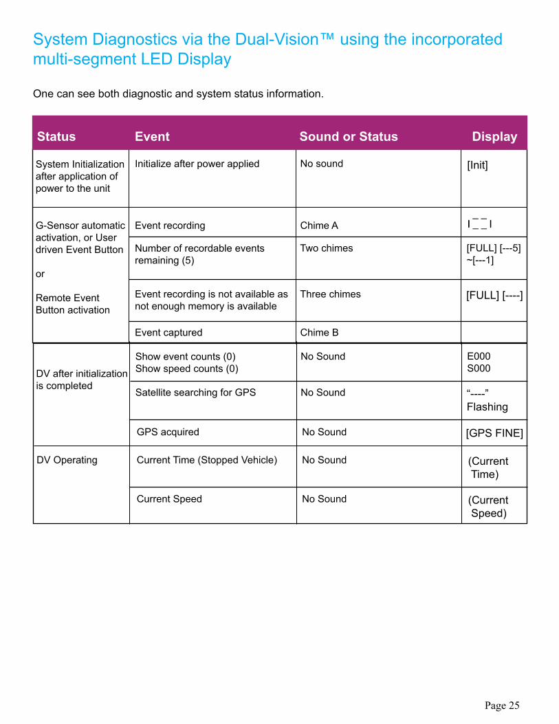
System Diagnostics via the Dual-Vision™ using the incorporated multi-segment LED Display
One can see both diagnostic and system status information.
Status Event Sound or Status Display
System Initializationafter application ofpower to the unit
DV Operating
G-Sensor automatic activation, or User driven Event Button
or
Remote EventButton activation
DV after initialization is completed
Initialize after power applied
Event recording
Number of recordable events remaining (5)
Show event counts (0) Show speed counts (0)
Event recording is not available as not enough memory is available
Satellite searching for GPS
GPS acquired
Current Time (Stopped Vehicle)
Current Speed
Event captured
No sound
Chime A
Two chimes
No Sound
Three chimes
No Sound
No Sound
No Sound
No Sound
Chime B
[Init]
[FULL] [---5] ~[---1]
E000 S000
[FULL] [----]
“----” Flashing
[GPS FINE]
(Current Time)
(Current Speed)
l _ _ l l _ _ l
Page 25
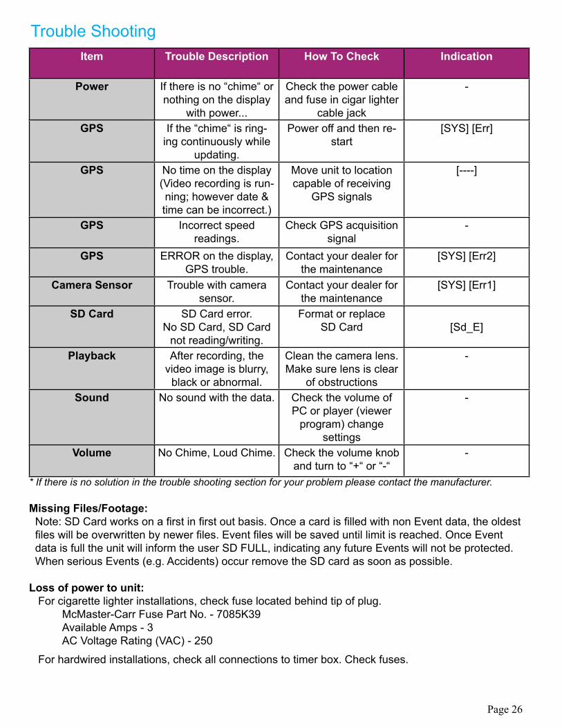
Item Trouble Description How To Check Indication
Power If there is no “chime“ or nothing on the display
with power...
Check the power cable and fuse in cigar lighter
cable jack
-
GPS If the “chime“ is ring-ing continuously while
updating.
Power off and then re-start
[SYS] [Err]
GPS No time on the display (Video recording is run-ning; however date & time can be incorrect.)
Move unit to location capable of receiving
GPS signals
[----]
GPS Incorrect speedreadings.
Check GPS acquisition signal
-
GPS ERROR on the display, GPS trouble.
Contact your dealer for the maintenance
[SYS] [Err2]
Camera Sensor Trouble with camera sensor.
Contact your dealer for the maintenance
[SYS] [Err1]
SD Card SD Card error.No SD Card, SD Card
not reading/writing.
Format or replaceSD Card [Sd_E]
Playback After recording, the video image is blurry,
black or abnormal.
Clean the camera lens. Make sure lens is clear
of obstructions
-
Sound No sound with the data. Check the volume of PC or player (viewer
program) changesettings
-
Volume No Chime, Loud Chime. Check the volume knob and turn to “+“ or “-“
-
* If there is no solution in the trouble shooting section for your problem please contact the manufacturer.
Missing Files/Footage: Note: SD Card works on a first in first out basis. Once a card is filled with non Event data, the oldest files will be overwritten by newer files. Event files will be saved until limit is reached. Once Event data is full the unit will inform the user SD FULL, indicating any future Events will not be protected. When serious Events (e.g. Accidents) occur remove the SD card as soon as possible.
Loss of power to unit: For cigarette lighter installations, check fuse located behind tip of plug. McMaster-Carr Fuse Part No. - 7085K39 Available Amps - 3 AC Voltage Rating (VAC) - 250
For hardwired installations, check all connections to timer box. Check fuses.
Trouble Shooting
Page 26
Page 27
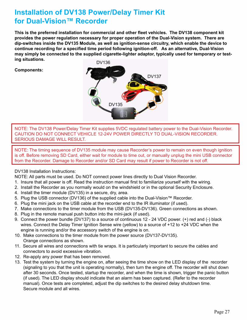
Installation of DV138 Power/Delay Timer Kitfor Dual-Vision™ Recorder This is the preferred installation for commercial and other fleet vehicles. The DV138 component kit provides the power regulation necessary for proper operation of the Dual-Vision system. There are dip-switches inside the DV135 Module, as well as ignition-sense circuitry, which enable the device to continue recording for a specified time period following ignition-off. As an alternative, Dual-Vision may simply be connected to the supplied cigarette-lighter adaptor, typically used for temporary or test-ing situations.
Components:
NOTE: The DV138 Power/Delay Timer Kit supplies 5VDC regulated battery power to the Dual-Vision Recorder. CAUTION DO NOT CONNECT VEHICLE 12-24V POWER DIRECTLY TO DUAL-VISION RECORDER.SERIOUS DAMAGE WILL RESULT.
NOTE: The timing sequence of DV135 module may cause Recorder’s power to remain on even though ignition is off. Before removing SD Card, either wait for module to time out, or manually unplug the mini USB connector from the Recorder. Damage to Recorder and/or SD Card may result if power to Recorder is not off.
DV138 Installation Instructions:NOTE: All parts must be used. Do NOT connect power lines directly to Dual Vision Recorder. 1. Insure that all power is off. Read the instruction manual first to familiarize yourself with the wiring.2. Install the Recorder as you normally would on the windshield or in the optional Security Enclosure.4. Install the timer module (DV135) in a secure, dry, area.5. Plug the USB connector (DV136) of the supplied cable into the Dual-Vision™ Recorder. 6. Plug the mini jack on the USB cable at the recorder end to the IR illuminator (if used).7. Make connections to the timer module from the USB (DV135-DV136). Green connections as shown.8. Plug in the remote manual push button into the mini-jack (if used).9. Connect the power bundle (DV137) to a source of continuous 12 - 24 VDC power. (+) red and (-) black wires. Connect the Delay Timer Ignition Sense wire (yellow) to a source of +12 to +24 VDC when the engine is running and/or the accessory switch of the engine is on.10. Make connections to the timer module from the power source (DV137-DV135). Orange connections as shown.11. Secure all wires and connections with tie wraps. It is particularly important to secure the cables and connectors to avoid excessive vibration.12. Re-apply any power that has been removed.13. Test the system by turning the engine on, after seeing the time show on the LED display of the recorder (signaling to you that the unit is operating normally), then turn the engine off. The recorder will shut down after 30 seconds. Once tested, startup the recorder, and when the time is shown, trigger the panic button (if used). The LED display should indicate that an alarm has been captured. (Refer to the recorder manual). Once tests are completed, adjust the dip switches to the desired delay shutdown time. Secure module and all wires.
DV137
DV135
DV136
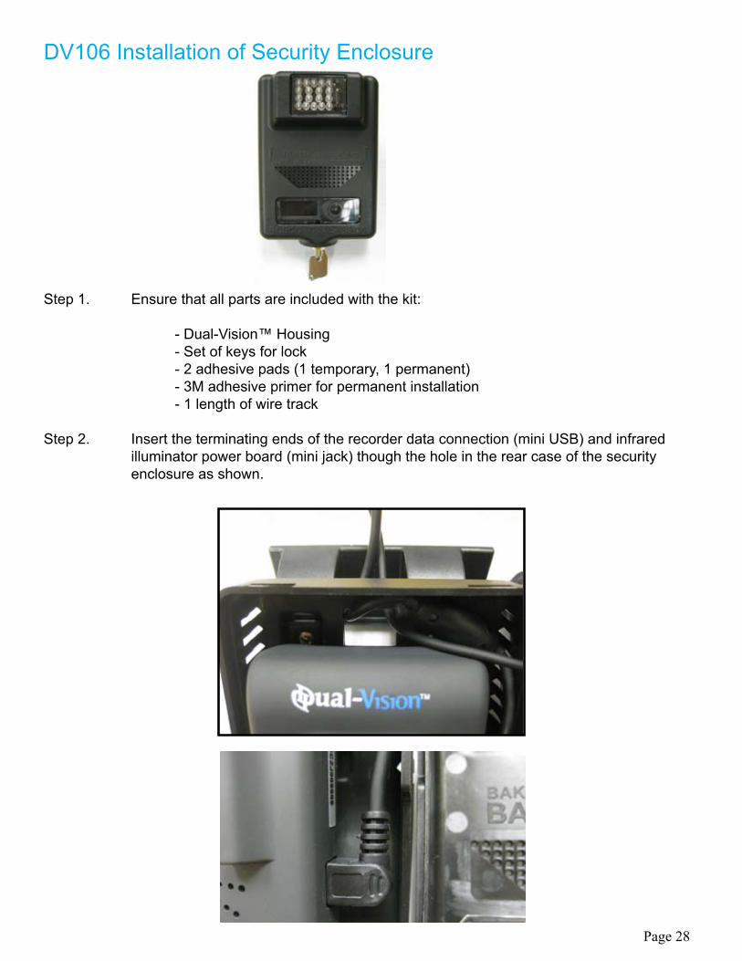
DV106 Installation of Security Enclosure
Step 1. Ensure that all parts are included with the kit:
- Dual-Vision™ Housing - Set of keys for lock - 2 adhesive pads (1 temporary, 1 permanent) - 3M adhesive primer for permanent installation - 1 length of wire track
Step 2. Insert the terminating ends of the recorder data connection (mini USB) and infrared illuminator power board (mini jack) though the hole in the rear case of the security enclosure as shown.
Page 28
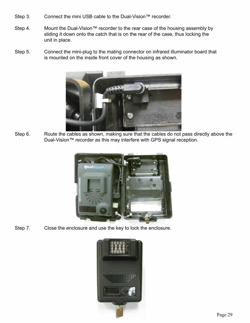
Step 3. Connect the mini USB cable to the Dual-Vision™ recorder.
Step 4. Mount the Dual-Vision™ recorder to the rear case of the housing assembly by sliding it down onto the catch that is on the rear of the case, thus locking the unit in place.
Step 5. Connect the mini-plug to the mating connector on infrared illuminator board that is mounted on the inside front cover of the housing as shown.
Step 6. Route the cables as shown, making sure that the cables do not pass directly above the Dual-Vision™ recorder as this may interfere with GPS signal reception.
Step 7. Close the enclosure and use the key to lock the enclosure.
Page 29
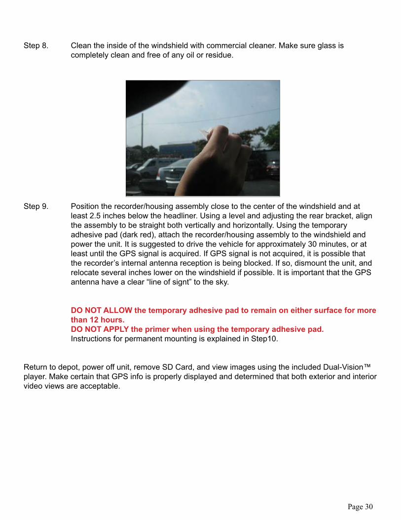
Step 8. Clean the inside of the windshield with commercial cleaner. Make sure glass is completely clean and free of any oil or residue.
Step 9. Position the recorder/housing assembly close to the center of the windshield and at least 2.5 inches below the headliner. Using a level and adjusting the rear bracket, align the assembly to be straight both vertically and horizontally. Using the temporary adhesive pad (dark red), attach the recorder/housing assembly to the windshield and power the unit. It is suggested to drive the vehicle for approximately 30 minutes, or at least until the GPS signal is acquired. If GPS signal is not acquired, it is possible that the recorder’s internal antenna reception is being blocked. If so, dismount the unit, and relocate several inches lower on the windshield if possible. It is important that the GPS antenna have a clear “line of signt” to the sky.
DO NOT ALLOW the temporary adhesive pad to remain on either surface for more than 12 hours. DO NOT APPLY the primer when using the temporary adhesive pad. Instructions for permanent mounting is explained in Step10.
Return to depot, power off unit, remove SD Card, and view images using the included Dual-Vision™ player. Make certain that GPS info is properly displayed and determined that both exterior and interior video views are acceptable.
Page 30
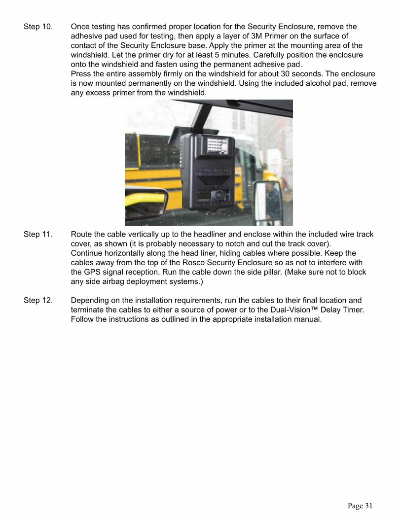
Step 10. Once testing has confirmed proper location for the Security Enclosure, remove the adhesive pad used for testing, then apply a layer of 3M Primer on the surface of contact of the Security Enclosure base. Apply the primer at the mounting area of the windshield. Let the primer dry for at least 5 minutes. Carefully position the enclosure onto the windshield and fasten using the permanent adhesive pad. Press the entire assembly firmly on the windshield for about 30 seconds. The enclosure is now mounted permanently on the windshield. Using the included alcohol pad, remove any excess primer from the windshield.
Step 11. Route the cable vertically up to the headliner and enclose within the included wire track cover, as shown (it is probably necessary to notch and cut the track cover). Continue horizontally along the head liner, hiding cables where possible. Keep the cables away from the top of the Rosco Security Enclosure so as not to interfere with the GPS signal reception. Run the cable down the side pillar. (Make sure not to block any side airbag deployment systems.)
Step 12. Depending on the installation requirements, run the cables to their final location and terminate the cables to either a source of power or to the Dual-Vision™ Delay Timer. Follow the instructions as outlined in the appropriate installation manual.
Page 31
We warrant that all ROSCO mirror, camera, sun visor, and electronic vision products are free from defects in workmanship and materials for a period of ONE (1) YEAR from the date of receipt of the product. During the warranty period, we agree to provide a replacement for (or at our option, repair) the ROSCO product and/or any one or more component parts of a ROSCO product. Which malfunctions under normal use and service.
Upon discovering a defect, the customer must contact ROSCO for a return authorization and then must return the product, and/or component part, together with proof of date of receipt of the product, to ROSCO INC. 144-31 91st Ave. Jamaica, New York 11435. The customer and not ROSCO will be responsible for the payment of all removal, installation and transportation charges for return of defective products or components to ROSCO. Transportation charges for such return must be prepaid. The repaired or replaced equipment will be returned to the customer with transportation charges prepaid by ROSCO. Replacement (or repaired) products and/or component parts are warranted only for the unexpired term of the original warranty.
This warranty does not cover defects caused by neglect, misuse, incorrect application, incorrect installation, water damage, vehicle wash facilities, alteration or repair in any manner outside ROSCO’s factory. Damage caused by the return shipment due to inadequate packaging or mishandling will also not be covered. If the alleged defect is due to any of these causes, the customer will be advised of the findings and asked what action is to be taken. If ROSCO is requested to repair the product, a repair charge estimate will be prepared and the customer’s written permission (purchase order, repair, etc.) will be necessary to proceed with the repair of the product and/or component part. Transportation charges for such returns will be the responsibility of the customer.
This warranty may not be expanded by oral representation, written sales information, drawings or otherwise. Repair or replacement is the exclusive remedy for defective products under this warranty. This warranty is expressly in lieu of all other warranties, including any implied warranty of merchantability or any implied warranty of fitness for a particular purpose on any ROSCO product. ROSCO shall not be liable for any consequential or incidental damages for breach of any express or implied warranty on any ROSCO product.
ROSCO COMMERCIAL WARRANTY