Embed Size (px)
Citation preview
1Internal Power Vent System EuropeanHome.com
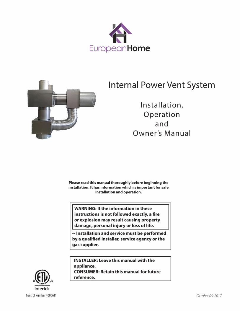
-- Installation and service must be performed by a qualified installer, service agency or the gas supplier.
WARNING: If the information in these instructions is not followed exactly, a fire or explosion may result causing property damage, personal injury or loss of life.
INSTALLER: Leave this manual with the appliance.CONSUMER: Retain this manual for future reference.
Installation, Operation
andOwner’s Manual
October 05, 2017
Internal Power Vent System
Please read this manual thoroughly before beginning the installation. It has information which is important for safe
installation and operation.
Control Number 4006611
2Internal Power Vent System EuropeanHome.com
TABLE OF CONTENTS
Important Safety Information 3
Product Information 4
Venting Requirements 8
Installation 11
Operating the System 18
Warranty Appendix A
3
IMPORTANT SAFETY INFORMATIONRead these instructions carefully before installing or operating this system.
Internal Power Vent System EuropeanHome.com
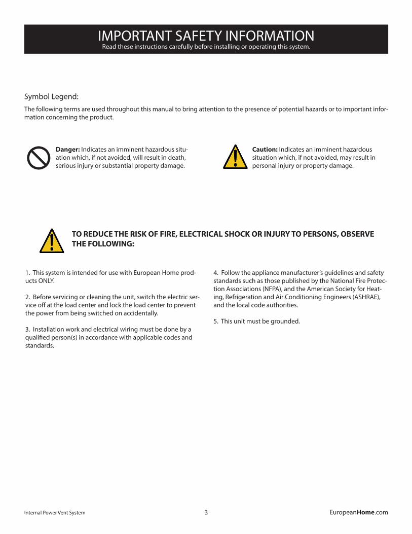
Symbol Legend:The following terms are used throughout this manual to bring attention to the presence of potential hazards or to important infor-mation concerning the product.
Danger: Indicates an imminent hazardous situ-ation which, if not avoided, will result in death, serious injury or substantial property damage.X
Caution: Indicates an imminent hazardous situation which, if not avoided, may result in personal injury or property damage.
TO REDUCE THE RISK OF FIRE, ELECTRICAL SHOCK OR INJURY TO PERSONS, OBSERVE THE FOLLOWING:
1. This system is intended for use with European Home prod-ucts ONLY.
2. Before servicing or cleaning the unit, switch the electric ser-vice off at the load center and lock the load center to prevent the power from being switched on accidentally.
3. Installation work and electrical wiring must be done by a qualified person(s) in accordance with applicable codes and standards.
4. Follow the appliance manufacturer’s guidelines and safety standards such as those published by the National Fire Protec-tion Associations (NFPA), and the American Society for Heat-ing, Refrigeration and Air Conditioning Engineers (ASHRAE), and the local code authorities.
5. This unit must be grounded.
PRODUCT INFORMATION
4Internal Power Vent System EuropeanHome.com
Thank you for purchasing an Internal Power Vent System (IPVS) by European Home. This system combines two great hearth product names; European Home and Enervex®. Where necessary, excerpts of the Enervex installation instructions are inserted into this manual and labeled with: ENERVEX®
OVERVIEW
The IPVS is approved for use with the entire line of Element4 fireplaces. It accepts 5” x 8” venting, must be mounted internally and used with wall-mounted terminations ONLY. The IPVS consists of six main components:
1. a PV-GS-SGV-02 solenoid valve2. a PV-WM-AS air separator (2 req’d.; PV-WM-FAS-01 and PV-WM-MAS-01)3. a PV-GS-CM-ADC 100 system control with included PDS 1 proven draft switch4. a PV-WM-146 power vent5. a PV-ES-PLS-WHT-02 system switch6. an E4-SA-WS-80 flame switch7. an installation manual
The PV-WM-146 fan, which creates negative pressure within the venting, is mounted between two PV-WM-AS separators, one of which is mounted directly to the outside wall of the building. Inside of the building, the PDS 1 proven draft switch senses the draft pressure and signals the system controller. Once the draft has been established the solenoid valve is opened, the ready light is lit and the fireplace can be operated as usual.
The above components are all connected by customer-supplied wiring which must be in accordance with the requirements of the authority having jurisdiction or, in the absence of such requirements, with the National Electrical Code, NFPA70.
The installation of your IPVS will follow the steps below and this manual is laid out accordingly.
• Installing the Fan and Fan Controls
• Installing the Solenoid Gas Valve
• Testing the System
As sold, the Enervex® components may be installed to accommodate a number of different fireplace models and types. However, when installed with an Element4 fireplace from European Home the Enervex® instructions excerpted in this manual are to be followed exclusively.
PRODUCT INFORMATION
5Internal Power Vent System EuropeanHome.com
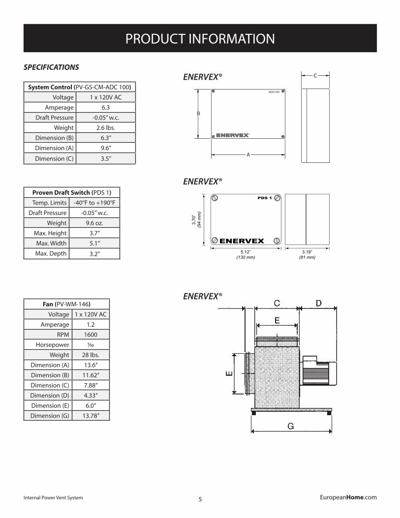
Fan (PV-WM-146)
Voltage 1 x 120V AC
Amperage 1.2
RPM 1600
Horsepower 1/10
Weight 28 lbs.
Dimension (A) 13.6”
Dimension (B) 11.62”
Dimension (C) 7.88”
Dimension (D) 4.33”
Dimension (E) 6.0”
Dimension (G) 13.78”
SPECIFICATIONS
System Control (PV-GS-CM-ADC 100)
Voltage 1 x 120V AC
Amperage 6.3
Draft Pressure -0.05” w.c.
Weight 2.6 lbs.
Dimension (B) 6.3”
Dimension (A) 9.6”
Dimension (C) 3.5”
Proven Draft Switch (PDS 1)
Temp. Limits -40°F to +190°F
Draft Pressure -0.05” w.c.
Weight 9.6 oz.
Max. Height 3.7”
Max. Width 5.1”
Max. Depth 3.2”
4
3916067 01.13
2.Specifications
2.1 Dimensions & Capacities
ADC100 ControlPower supply V 1x120VACAmperage A 6.3Operating temperature °F/°C -4 to 122 / -20 to 50Control signal mA max. 10Control relay Max. 120 VAC / 8A Output VAC 10-120
VDC 0-10Post Purge Time 0-3 MinutesAlarm Delay Time 15 SecondsDimensions A in/mm 9.6 / 244
B in/mm 6.3 / 160C in/mm 3.5 / 90
Weight lbs/kg 2.6 / 1.2Chimney ProbeDimensions D in/mm 4.25 / 108
E in/mm 3.50 / 89
B
A
C
ADC100
E
D
ADC100
2
3903001 05.12
1. Product Information .............................................................................................................2
2. Specifications .............................................................................................................2
3. MechanicalInstallation .............................................................................................................3
4. ElectricalInstallation .............................................................................................................4 5. StartupandConfiguration .............................................................................................................4
1. Product Information
1.1 FunctionUse The PDS 1, Proven Draft Switch, is a fixed position differential pressure switch that is used in conjunction with ENERVEX’s Mechanical Draft Systems for insufficient draft protection. If an unsafe draft condition occurs, whether this is caused by mechanical or electrical failure, the switch will shut down the heating appliance. It is typically used with gas or oil fired appliances where it can be interlocked with the gas supply valve or the safety or control circuit of the appliance.
Construction The enclosure, the switch housing and the internal switch are made of polycarbonate. The diaphragm is madeofNBR(silicone),whiletheswitchingcontactismadeinfinesilver.
Listings The switch is UL recognized product
1.2ComponentsStandard packinglist The PDS shipment contains: - 1 PDS 1 Differential Pressure Switch - Duct Kit consisting of stack probe with mounting flange and 6 ft silicone tubing If other components are shipped, they will appear as separate items on the shipping packing list.
1.3 Warranty CompletewarrantyconditionsareavailablefromENERVEX,Inc.
2.Specifications
2.1Dimensions&Capacities
PDS 1Maximum Load V 1x120 VAC
Amperage A 3
Range of Operation inWC/Pa .05 to .50/13 to 135
Temperature Limits oF/oC -40 to +190/ -40 to +88
Max. Pressure PSI/mbar 3 / 207
Wiring Connections 1/4” Solderless Quick Con-nect Terminals
Pressure Connections Two plastic tubes, outside diameter of 1/4” (6.0mm)
Weight oz. / kg 9.6 / 0.275
ENERVEX
PDS 1
5.12” (130 mm)
3.70
” (9
4 m
m)
3.19” (81 mm)
ENERVEX®
ENERVEX®
ENERVEX®
PRODUCT INFORMATION
6Internal Power Vent System EuropeanHome.com
3
3903001 05.12
3.MechanicalInstallation
3.1InstallationofProvenDraftSwitch(PDS1)
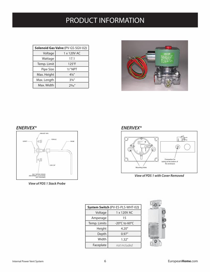
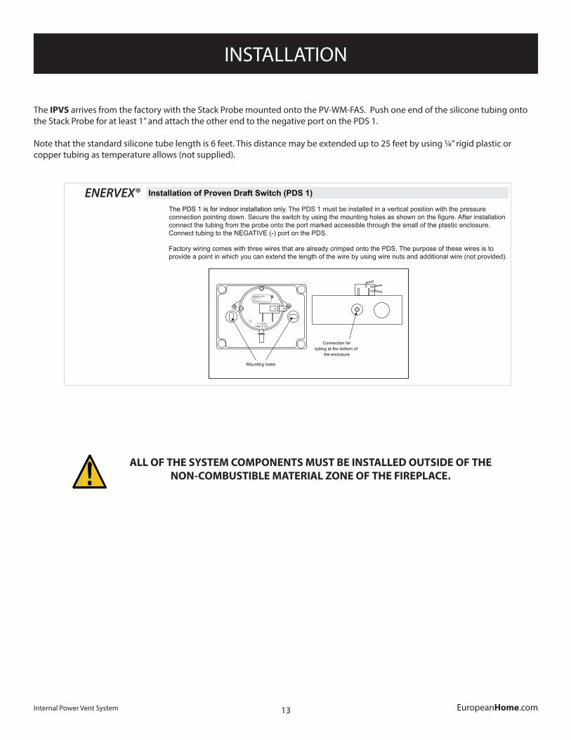
The PDS 1 is for indoor installation only. The PDS 1 must be installed in a vertical position with the pressure connectionpointingdown.Securetheswitchbyusingthemountingholesasshownonthefigure.Afterinstallation connect the tubing from the probe onto the port marked accessible through the small of the plastic enclosure. Connect tubing to the NEGATIVE (-) port on the PDS.
Factory wiring comes with three wires that are already crimped onto the PDS. The purpose of these wires is to provide a point in which you can extend the length of the wire by using wire nuts and additional wire (not provided).
3.2InstallationofStackProbeforPDS1
A stack probe is used with ENERVEX Proven Draft Switches (PDS). The PDS 1 monitors the pressure inside the stack and signals the control to shut down the applianceifinsufficientdraftexistsinsidethestack.The probe must be installed between the appliance and the exhaust fan.
For all installations, the stack probe must be placed sotheflowthroughthestackisperpendiculartothetip of the probe. Locate the probe at least the distance “A” away from any elbows or tees in the stack. Thedistance“A”isdefinedasatleast three(3)ventdiameters;A≥3*V(seefigurebelow).To prevent condensation from entering the probe or PDS when installed on a horizontal stack, the probe must be installed above the centerline of the stack. For fireplaceinstallations,thestackprobeshouldbe installed as close to the exhaust fan as possible.
ENERVEX
ENDURA PLASTICSXP042105-1-1REV A0.05” WC PRMOUNT DIAPHRAGM VERTICAL
UR
Mounting holes
Connection fortubing at the bottom of
the enclosure
BRACKET ASM.
SELF TAPPING SCREWS(RECOMMEND 1/4-20 OR M6)
(NOT PROVIDED)
GASKET PROBE
FERRULE
END CAP
ENERVEX®
View of PDS 1 with Cover Removed
3
3903001 05.12
3.MechanicalInstallation
3.1InstallationofProvenDraftSwitch(PDS1)
The PDS 1 is for indoor installation only. The PDS 1 must be installed in a vertical position with the pressure connectionpointingdown.Securetheswitchbyusingthemountingholesasshownonthefigure.Afterinstallation connect the tubing from the probe onto the port marked accessible through the small of the plastic enclosure. Connect tubing to the NEGATIVE (-) port on the PDS.
Factory wiring comes with three wires that are already crimped onto the PDS. The purpose of these wires is to provide a point in which you can extend the length of the wire by using wire nuts and additional wire (not provided).
3.2InstallationofStackProbeforPDS1
A stack probe is used with ENERVEX Proven Draft Switches (PDS). The PDS 1 monitors the pressure inside the stack and signals the control to shut down the applianceifinsufficientdraftexistsinsidethestack.The probe must be installed between the appliance and the exhaust fan.
For all installations, the stack probe must be placed sotheflowthroughthestackisperpendiculartothetip of the probe. Locate the probe at least the distance “A” away from any elbows or tees in the stack. Thedistance“A”isdefinedasatleast three(3)ventdiameters;A≥3*V(seefigurebelow).To prevent condensation from entering the probe or PDS when installed on a horizontal stack, the probe must be installed above the centerline of the stack. For fireplaceinstallations,thestackprobeshouldbe installed as close to the exhaust fan as possible.
ENERVEX
ENDURA PLASTICSXP042105-1-1REV A0.05” WC PRMOUNT DIAPHRAGM VERTICAL
UR
Mounting holes
Connection fortubing at the bottom of
the enclosure
BRACKET ASM.
SELF TAPPING SCREWS(RECOMMEND 1/4-20 OR M6)
(NOT PROVIDED)
GASKET PROBE
FERRULE
END CAP
View of PDS 1 Stack Probe
ENERVEX®
System Switch (PV-ES-PLS-WHT-02)
Voltage 1 x 120V AC
Amperage 15
Temp. Limits -20°C to 60°C
Height 4.20”
Depth 0.97”
Width 1.32”
Faceplate not included
Solenoid Gas Valve (PV-GS-SGV-02)
Voltage 1 x 120V AC
Wattage 17.1
Temp. Limit 125°F
Pipe Size 1/2” NPT
Max. Height 41/8”
Max. Length 33/4”
Max. Width 29/16”
PRODUCT INFORMATION
7Internal Power Vent System EuropeanHome.com
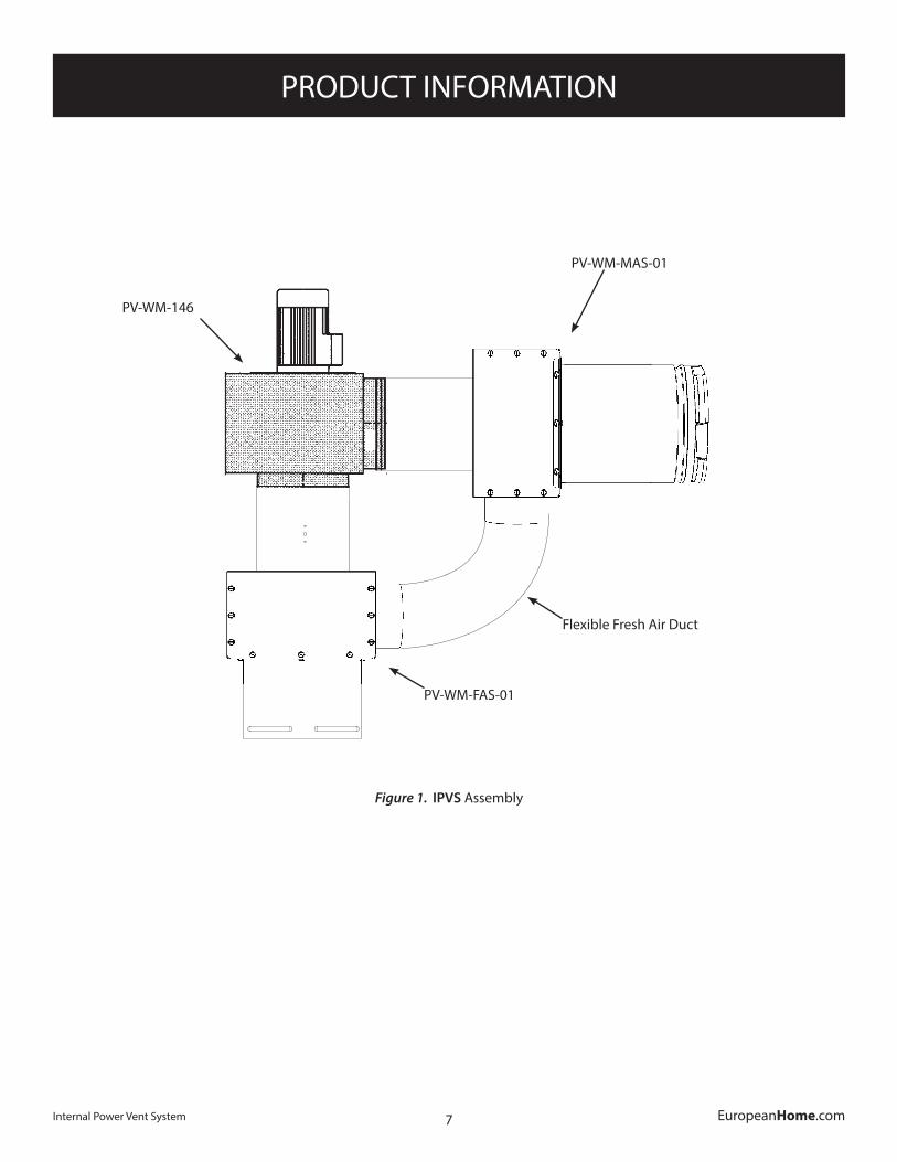
Figure 1. IPVS Assembly
PV-WM-MAS-01
PV-WM-FAS-01
PV-WM-146
Flexible Fresh Air Duct
VENTING REQUIREMENTS
8Internal Power Vent System EuropeanHome.com
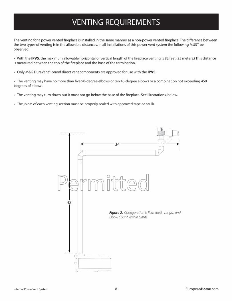
The venting for a power vented fireplace is installed in the same manner as a non-power vented fireplace. The difference between the two types of venting is in the allowable distances. In all installations of this power vent system the following MUST be observed:
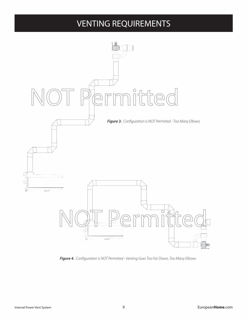
• With the IPVS, the maximum allowable horizontal or vertical length of the fireplace venting is 82 feet (25 meters.) This distance is measured between the top of the fireplace and the base of the termination. • Only M&G DuraVent®-brand direct vent components are approved for use with the IPVS. • The venting may have no more than five 90-degree elbows or ten 45-degree elbows or a combination not exceeding 450 ‘degrees of elbow’.
• The venting may turn down but it must not go below the base of the fireplace. See illustrations, below.
• The joints of each venting section must be properly sealed with approved tape or caulk.
34’
42’
Figure 2. Configuration is Permitted - Length and Elbow Count Within Limits
VENTING REQUIREMENTS
9Internal Power Vent System EuropeanHome.com
Figure 4. Configuration is NOT Permitted - Venting Goes Too Far Down, Too Many Elbows
Figure 3. Configuration is NOT Permitted - Too Many Elbows
VENTING REQUIREMENTS
10Internal Power Vent System EuropeanHome.com
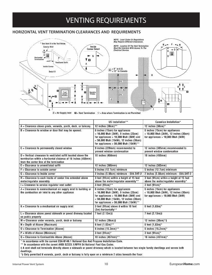
HORIZONTAL VENT TERMINATION CLEARANCES AND REQUIREMENTS
11
INSTALLATION
Internal Power Vent System EuropeanHome.com
INSTALLING the FAN and FAN CONTROLS
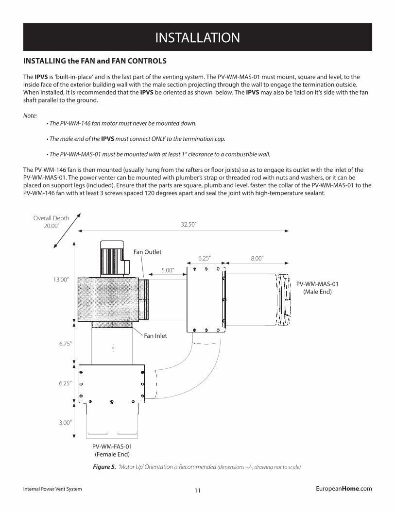
The IPVS is ‘built-in-place’ and is the last part of the venting system. The PV-WM-MAS-01 must mount, square and level, to the inside face of the exterior building wall with the male section projecting through the wall to engage the termination outside. When installed, it is recommended that the IPVS be oriented as shown below. The IPVS may also be ‘laid on it’s side with the fan shaft parallel to the ground.
Note: • The PV-WM-146 fan motor must never be mounted down.
• The male end of the IPVS must connect ONLY to the termination cap.
• The PV-WM-MAS-01 must be mounted with at least 1” clearance to a combustible wall.
The PV-WM-146 fan is then mounted (usually hung from the rafters or floor joists) so as to engage its outlet with the inlet of the PV-WM-MAS-01. The power venter can be mounted with plumber’s strap or threaded rod with nuts and washers, or it can be placed on support legs (included). Ensure that the parts are square, plumb and level, fasten the collar of the PV-WM-MAS-01 to the PV-WM-146 fan with at least 3 screws spaced 120 degrees apart and seal the joint with high-temperature sealant.
Figure 5. ‘Motor Up’ Orientation is Recommended (dimensions +/-, drawing not to scale)
6.25” 8.00”
6.25”
3.00”
5.00”
6.75”
PV-WM-MAS-01(Male End)
Fan Outlet
Fan Inlet
PV-WM-FAS-01(Female End)
32.50”
13.00”
Overall Depth 20.00”
12
INSTALLATION
Internal Power Vent System EuropeanHome.com
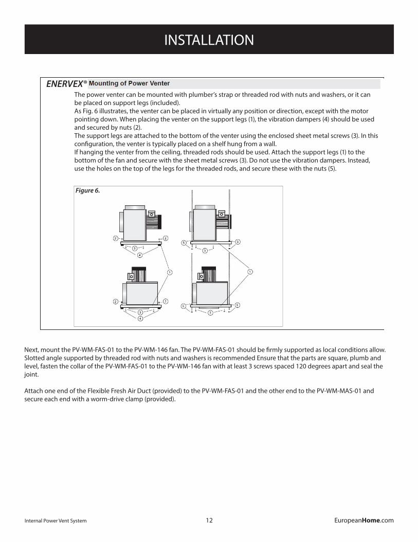
ENERVEX®The power venter can be mounted with plumber’s strap or threaded rod with nuts and washers, or it can be placed on support legs (included).As Fig. 6 illustrates, the venter can be placed in virtually any position or direction, except with the motor pointing down. When placing the venter on the support legs (1), the vibration dampers (4) should be used and secured by nuts (2).The support legs are attached to the bottom of the venter using the enclosed sheet metal screws (3). In this configuration, the venter is typically placed on a shelf hung from a wall.If hanging the venter from the ceiling, threaded rods should be used. Attach the support legs (1) to the bottom of the fan and secure with the sheet metal screws (3). Do not use the vibration dampers. Instead, use the holes on the top of the legs for the threaded rods, and secure these with the nuts (5).
Figure 6.
Next, mount the PV-WM-FAS-01 to the PV-WM-146 fan. The PV-WM-FAS-01 should be firmly supported as local conditions allow. Slotted angle supported by threaded rod with nuts and washers is recommended Ensure that the parts are square, plumb and level, fasten the collar of the PV-WM-FAS-01 to the PV-WM-146 fan with at least 3 screws spaced 120 degrees apart and seal the joint.
Attach one end of the Flexible Fresh Air Duct (provided) to the PV-WM-FAS-01 and the other end to the PV-WM-MAS-01 and secure each end with a worm-drive clamp (provided).
13
INSTALLATION
Internal Power Vent System EuropeanHome.com
ALL OF THE SYSTEM COMPONENTS MUST BE INSTALLED OUTSIDE OF THE NON-COMBUSTIBLE MATERIAL ZONE OF THE FIREPLACE.
3
3903001 05.12
3.MechanicalInstallation
3.1InstallationofProvenDraftSwitch(PDS1)
The PDS 1 is for indoor installation only. The PDS 1 must be installed in a vertical position with the pressure connectionpointingdown.Securetheswitchbyusingthemountingholesasshownonthefigure.Afterinstallation connect the tubing from the probe onto the port marked accessible through the small of the plastic enclosure. Connect tubing to the NEGATIVE (-) port on the PDS.
Factory wiring comes with three wires that are already crimped onto the PDS. The purpose of these wires is to provide a point in which you can extend the length of the wire by using wire nuts and additional wire (not provided).
3.2InstallationofStackProbeforPDS1
A stack probe is used with ENERVEX Proven Draft Switches (PDS). The PDS 1 monitors the pressure inside the stack and signals the control to shut down the applianceifinsufficientdraftexistsinsidethestack.The probe must be installed between the appliance and the exhaust fan.
For all installations, the stack probe must be placed sotheflowthroughthestackisperpendiculartothetip of the probe. Locate the probe at least the distance “A” away from any elbows or tees in the stack. Thedistance“A”isdefinedasatleast three(3)ventdiameters;A≥3*V(seefigurebelow).To prevent condensation from entering the probe or PDS when installed on a horizontal stack, the probe must be installed above the centerline of the stack. For fireplaceinstallations,thestackprobeshouldbe installed as close to the exhaust fan as possible.
ENERVEX
ENDURA PLASTICSXP042105-1-1REV A0.05” WC PRMOUNT DIAPHRAGM VERTICAL
UR
Mounting holes
Connection fortubing at the bottom of
the enclosure
BRACKET ASM.
SELF TAPPING SCREWS(RECOMMEND 1/4-20 OR M6)
(NOT PROVIDED)
GASKET PROBE
FERRULE
END CAP
ENERVEX®
The IPVS arrives from the factory with the Stack Probe mounted onto the PV-WM-FAS. Push one end of the silicone tubing onto the Stack Probe for at least 1” and attach the other end to the negative port on the PDS 1.
Note that the standard silicone tube length is 6 feet. This distance may be extended up to 25 feet by using 1/4” rigid plastic or copper tubing as temperature allows (not supplied).
14
INSTALLATION
Internal Power Vent System EuropeanHome.com
5
3916067 01.13
3. Mechanical Installation
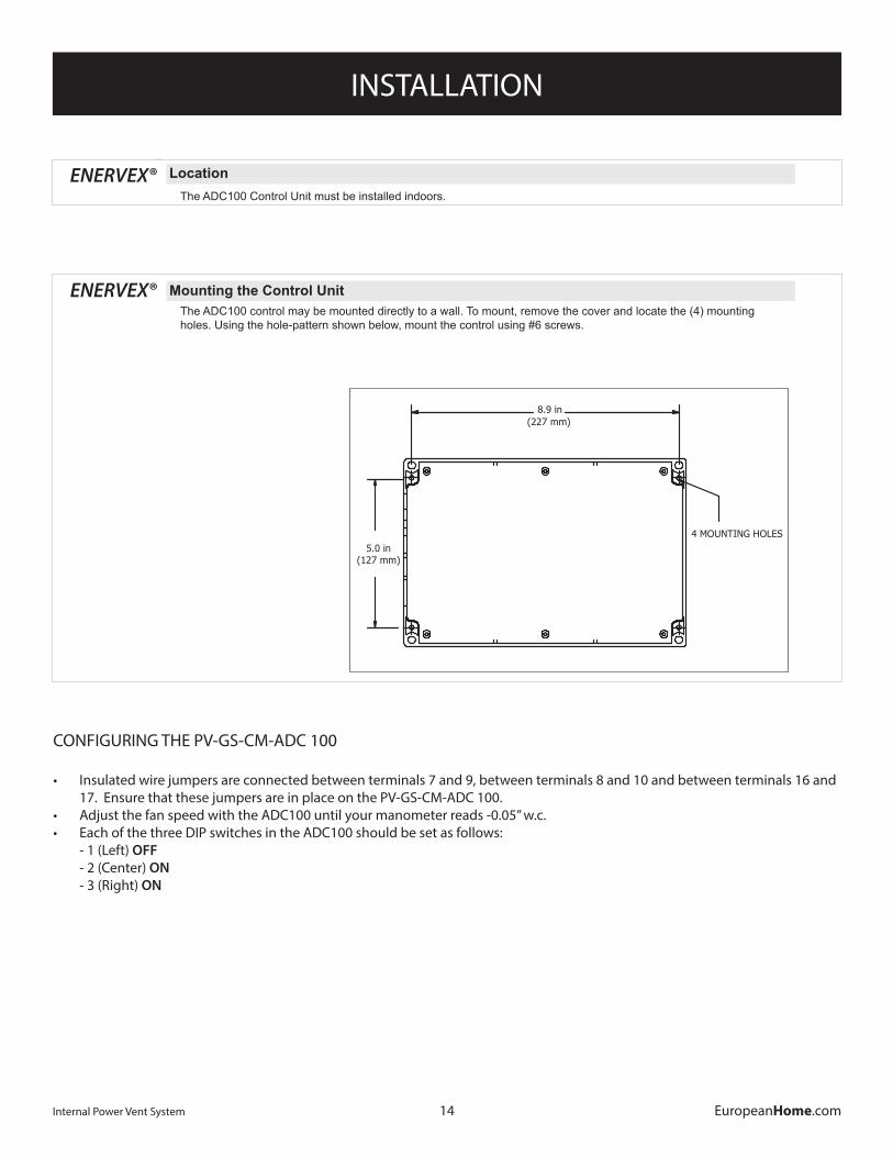
3.1 Location The ADC100 Control Unit must be installed indoors.
As shown in the diagram below, the control will be wired directly to a 120/1/60 VAC power supply. The control will also be connected to the fan, appliance and damper (if used). For detailed wiring information, see Chapter 4.
3.2MountingtheControlUnit The ADC100 control may be mounted directly to a wall. To mount, remove the cover and locate the (4) mounting holes. Using the hole-pattern shown below, mount the control using #6 screws. Once it is attached, wire the unit in accordance with Chapter 4.
ADC100
ENERVEX
ENERVEX
ADC100
PDS1
ADC100
DAMPER(SOLDSEPARATELY)
Fig.1
4 MOUNTING HOLES5.0 in
(127 mm)
8.9 in(227 mm)
Fig.2
ENERVEX®
5
3916067 01.13
3. Mechanical Installation
3.1 Location The ADC100 Control Unit must be installed indoors.
As shown in the diagram below, the control will be wired directly to a 120/1/60 VAC power supply. The control will also be connected to the fan, appliance and damper (if used). For detailed wiring information, see Chapter 4.
3.2MountingtheControlUnit The ADC100 control may be mounted directly to a wall. To mount, remove the cover and locate the (4) mounting holes. Using the hole-pattern shown below, mount the control using #6 screws. Once it is attached, wire the unit in accordance with Chapter 4.
ADC100
ENERVEX
ENERVEX
ADC100
PDS1
ADC100
DAMPER(SOLDSEPARATELY)
Fig.1
4 MOUNTING HOLES5.0 in
(127 mm)
8.9 in(227 mm)
Fig.2
ENERVEX®
CONFIGURING THE PV-GS-CM-ADC 100
• Insulated wire jumpers are connected between terminals 7 and 9, between terminals 8 and 10 and between terminals 16 and 17. Ensure that these jumpers are in place on the PV-GS-CM-ADC 100.
• Adjust the fan speed with the ADC100 until your manometer reads -0.05” w.c. • Each of the three DIP switches in the ADC100 should be set as follows:
- 1 (Left) OFF - 2 (Center) ON - 3 (Right) ON
15
INSTALLATION
Internal Power Vent System EuropeanHome.com
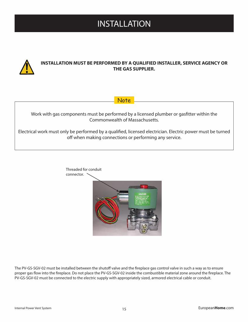
INSTALLATION MUST BE PERFORMED BY A QUALIFIED INSTALLER, SERVICE AGENCY OR THE GAS SUPPLIER.
Work with gas components must be performed by a licensed plumber or gasfitter within the Commonwealth of Massachusetts.
Electrical work must only be performed by a qualified, licensed electrician. Electric power must be turned off when making connections or performing any service.
Note
The PV-GS-SGV-02 must be installed between the shutoff valve and the fireplace gas control valve in such a way as to ensure proper gas flow into the fireplace. Do not place the PV-GS-SGV-02 inside the combustible material zone around the fireplace. The PV-GS-SGV-02 must be connected to the electric supply with appropriately sized, armored electrical cable or conduit.
Threaded for conduit connector.
16
INSTALLATION
Internal Power Vent System EuropeanHome.com
1 x 120V ACN
EnervexRSxx
DISCONNECT(by others)
FAN OUT 24VDC AUX 1 IN
ADC100
AC IN
L1
•
•
POWERSWITCH
1 2 7 109854AUX 1 OUT
2322PDS IN
131211
PDS-1
NO NC C
DAMPER PROVE
1716
• •
SOLENOIDGAS
VALVE
••INDICATOR
LAMP
••
• • • • • • • • • • • • • • •
• • •
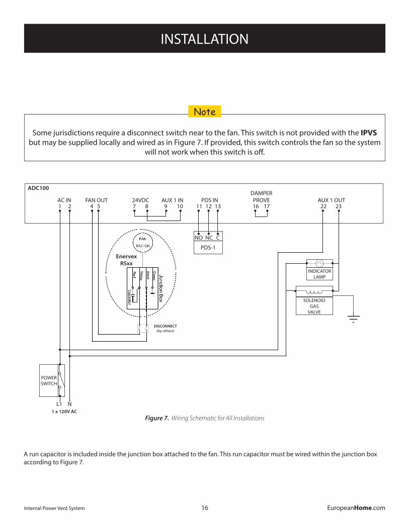
Figure 7. Wiring Schematic for All Installations
Some jurisdictions require a disconnect switch near to the fan. This switch is not provided with the IPVS but may be supplied locally and wired as in Figure 7. If provided, this switch controls the fan so the system
will not work when this switch is off.
Note
A run capacitor is included inside the junction box attached to the fan. This run capacitor must be wired within the junction box according to Figure 7.
17
INSTALLATION
Internal Power Vent System EuropeanHome.com
PV-ES-PLS-WHTThis part is delivered as two devices; light
and switch.
Ç
Ç
On-Off
E4-SA-WS-80This part has a 26’ ca-ble (which may NOT be extended) con-nected to the fireplace
control.
Gas ControlPV-GS-SGV-01This part must be installed in the gas supply upstream of the
fireplace.
Fireplace
Power Vent
PV-GS-CM-ADC 100This part must be in-
stalled indoors.
PDSThis part must be installed indoors.
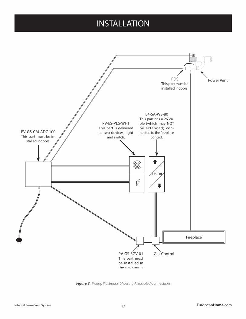
Figure 8. Wiring Illustration Showing Associated Connections
18
INSTALLATION
Internal Power Vent System EuropeanHome.com
Figure 7 shows the electrical connections in schematic format with no attention to relative component mounting distances.
Figure 8 is an illustration which is intended to help the installer locate the components in an average installation.
While all parts are subject to local and national code restrictions and limitations some parts have distance limitations and requirements.
- The E4-SA-SW-80 wall switch has a low voltage, proprietary, built-in 26’ connection cable which may NOT be modified or extended. The placement of this switch is limited by its cable length and it must be connected to the fireplace control module.
- The PV-ES-PLS-WHT-02 system switch should be placed next to E4-SA-SW-80 wall switch for convenience.
- The PV-GS-SGV-02 solenoid valve must be connected as close as practical to the gas control valve and after, as the gas flows, the gas shutoff valve.
- The PDS 1 stack probe may be extended up to 25 feet by using 1/4” rigid plastic or copper tubing as temperature allows (not supplied). The PDS 1 must be wired to the PV-GS-CM-ADC 100 with 3-conductor, shielded, 24 AWG cable; maximum length 300 feet.
9
3916067 01.13
ADC 100
To Fireplace
ENERVEX
Fig.7
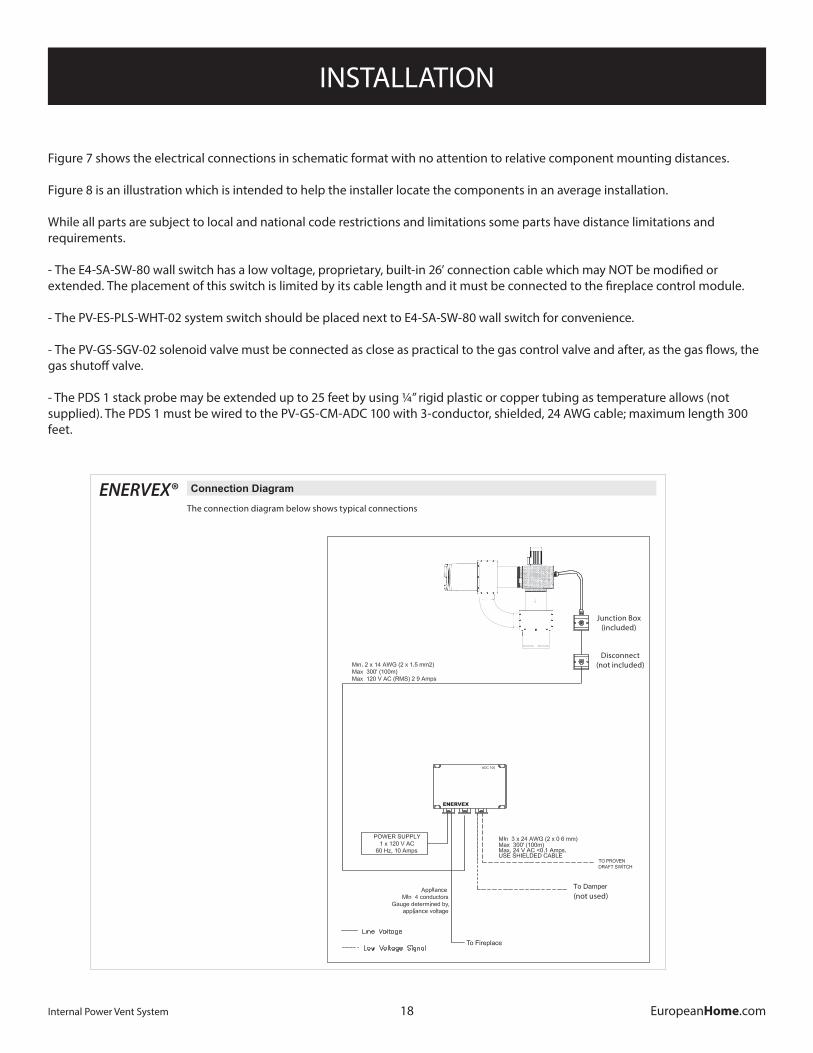
4.2ConnectionDiagram
The connection diagram shown in Fig. 7 below shows typical connections for a single phase fan. If a 3-phase fan is used, a VFD must be connected between the fan and control.
ENERVEX®The connection diagram below shows typical connections
(not used)
Junction Box(included)
Disconnect(not included)
19
INSTALLATION
Internal Power Vent System EuropeanHome.com
DIP Switch
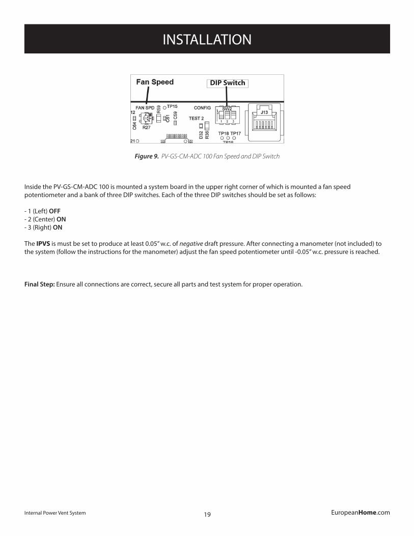
Figure 9. PV-GS-CM-ADC 100 Fan Speed and DIP Switch
Inside the PV-GS-CM-ADC 100 is mounted a system board in the upper right corner of which is mounted a fan speed potentiometer and a bank of three DIP switches. Each of the three DIP switches should be set as follows:
- 1 (Left) OFF - 2 (Center) ON - 3 (Right) ON
The IPVS is must be set to produce at least 0.05” w.c. of negative draft pressure. After connecting a manometer (not included) to the system (follow the instructions for the manometer) adjust the fan speed potentiometer until -0.05” w.c. pressure is reached.
Final Step: Ensure all connections are correct, secure all parts and test system for proper operation.
OPERATING the SYSTEM
20Internal Power Vent System EuropeanHome.com
TURNING THE SYSTEM ON Turn the PV-ES-PLS-WHT-02 switch to the ON position. The fan will provide negative pressure (draft). Once the fan has generated enough draft to reach the draft set-point, the PV-ES-PLS-WHT-02 indicator lamp will light and the PV-GS-SGV-02 valve will open. The gas fireplace is now ready for normal operation via the E4-SA-WS-80 wall switch or the remote control. The E4-SA-WS-80 wall switch has three buttons on it; On/Off, UP flame, DOWN flame. Press the On/Off button to begin the start-up sequence. After the main burner has lit the UP flame or DOWN flame button may be used as desired. Note that on multiple burner models the secondary burner(s) cannot be controlled by the wall switch, the remote control must be used.
TURNING THE SYSTEM OFF First, turn the gas fireplace off using the either E4-SA-WS-80 wall switch or the remote control then turn the PV-ES-PLS-WHT-02 switch OFF. The indicator lamp and the gas both turn off.
OPERATING the SYSTEM
21Internal Power Vent System EuropeanHome.com
TROUBLESHOOTING
22Internal Power Vent System EuropeanHome.com
14
3916067 01.13
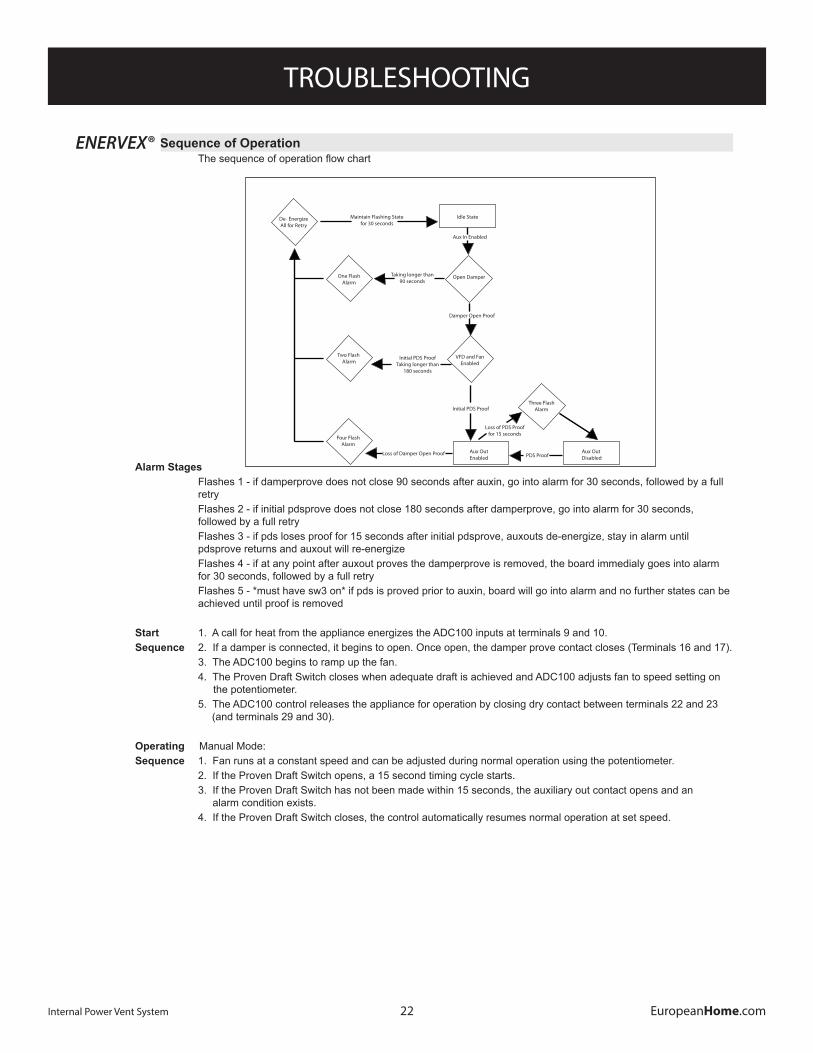
5.2 Sequence of Operation Thesequenceofoperationflowchartisshowninfigure11below.
Fig.11
AlarmStages Flashes 1 - if damperprove does not close 90 seconds after auxin, go into alarm for 30 seconds, followed by a full retry Flashes 2 - if initial pdsprove does not close 180 seconds after damperprove, go into alarm for 30 seconds, followed by a full retry Flashes 3 - if pds loses proof for 15 seconds after initial pdsprove, auxouts de-energize, stay in alarm until pdsprove returns and auxout will re-energize Flashes 4 - if at any point after auxout proves the damperprove is removed, the board immedialy goes into alarm for 30 seconds, followed by a full retry Flashes 5 - *must have sw3 on* if pds is proved prior to auxin, board will go into alarm and no further states can be achieved until proof is removed
Start 1. A call for heat from the appliance energizes the ADC100 inputs at terminals 9 and 10. Sequence 2. If a damper is connected, it begins to open. Once open, the damper prove contact closes (Terminals 16 and 17). 3. The ADC100 begins to ramp up the fan. 4. The Proven Draft Switch closes when adequate draft is achieved and ADC100 adjusts fan to speed setting on the potentiometer. 5. The ADC100 control releases the appliance for operation by closing dry contact between terminals 22 and 23 (and terminals 29 and 30).
Operating Manual Mode:Sequence 1. Fan runs at a constant speed and can be adjusted during normal operation using the potentiometer. 2. If the Proven Draft Switch opens, a 15 second timing cycle starts. 3. If the Proven Draft Switch has not been made within 15 seconds, the auxiliary out contact opens and an alarm condition exists. 4. If the Proven Draft Switch closes, the control automatically resumes normal operation at set speed.
Maintain Flashing Statefor 30 seconds
Taking longer than 90 seconds
Initial PDS ProofTaking longer than
180 seconds
Loss of Damper Open Proof
Aux In Enabled
Damper Open Proof
Initial PDS Proof
Loss of PDS Prooffor 15 seconds
PDS Proof
De- EnergizeAll for Retry
One FlashAlarm
Two Flash Alarm
Four FlashAlarm
Aux OutEnabled
Aux Out Disabled
Three FlashAlarm
Open Damper
Idle State
VFD and FanEnabled
ENERVEX®
TROUBLESHOOTING
23Internal Power Vent System EuropeanHome.com
15
3916067 01.13
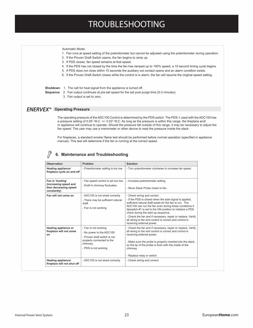
Observation Problem SolutionHeatingappliance/fireplacecycleonandoff
- Potentiometer setting is too low - Turn potentiometer clockwise to increase fan speed.
Fanis‘hunting’(increasingspeedandthendecreasingspeedconstantly)
- Fan speed control is set too low.-Draftinchimneyfluctuates.
- Increase potentiometer setting.
- Move Stack Probe closer to fan.
Fan will not come on - ADC100 is not wired correctly-Theremaybesufficientnaturaldraft- Fan is not working
- Check wiring and correct- If the PDS is closed when the start signal is applied, sufficientnaturaldraftexistsforthefantorun.TheADC100 can run the fan even during these conditions if dipswitch #1 is set to the ON position to initialize a PDS check during the start up sequence.- Check the fan and if necessary, repair or replace. Verify all wiring to fan and control is correct and control is receiving external power.
Heatingapplianceorfireplacewillnotcomeon
- Fan is not working- No power to the ADC100- Proven draft switch is not properly connected to the chimney.- PDS is not working
- Check the fan and if necessary, repair or replace. Verify all wiring to fan and control is correct and control is receiving external power.
- Make sure the probe is properly inserted into the stack, sothetipoftheprobeisflushwiththeinsideofthechimney.
- Replace relay or switch
Heatingappliance/fireplacewillnotshutoff
- ADC100 is not wired correctly - Check wiring and correct.
6.MaintenanceandTroubleshooting
5.3OperatingPressure The operating pressure of the ADC100 Control is determined by the PDS switch. The PDS-1 used with the ADC100 has apressuresettingof0.05”W.C.+/-0.03”W.C.Aslongasthepressureiswithinthisrange,thefireplaceand/ or appliance will continue to operate. Should the pressure fall outside of this range, it may be necessary to adjust the fan speed. The user may use a manometer or other device to read the pressure inside the stack. Forfireplaces,astandardsmoke/flametestshouldbeperformedbeforenormaloperation(specifiedinappliance manual). This test will determine if the fan is running at the correct speed.
Automatic Mode: 1. Fan runs at speed setting of the potentiometer but cannot be adjusted using the potentiometer during operation. 2. If the Proven Draft Switch opens, the fan begins to ramp up. 3. If PDS closes, fan speed remains at that speed. 4. If the PDS has not closed by the time the fan has ramped up to 100% speed, a 10 second timing cycle begins. 5. If PDS does not close within 15 seconds the auxiliary out contact opens and an alarm condition exists. 6. If the Proven Draft Switch closes while the control is in alarm, the fan will resume the original speed setting.
Shutdown 1. The call for heat signal from the appliance is turned off.Sequence 2. Fan output continues at pre-set speed for the set post purge time (0-3 minutes). 3. Fan output is set to zero.
ENERVEX®
24Internal Power Vent System EuropeanHome.com
European Home Warrantyfor
The Internal Power Vent System
European Home warrants this product against defects in materials and workmanship for a period of ONE (1) YEAR from the date of original retail purchase. If a defect exists, European Home will, at its option, either (1) provide needed components using new or refurbished replacement parts or (2) exchange the product with one which is new or which has been manufactured from new or serviceable used parts and is at least functionally equivalent to the original product. A replacement product/part assumes the remaining warranty of the original product or ninety (90) days from the date of replacement or repair, whichever provides longer coverage for you. When a product or part is exchanged, any replacement item becomes your property and the replaced item becomes the property of European Home. All warranty claims must be submitted through the dealer from which you purchased the product. Check with your dealer in advance for any costs to you when arranging a warranty call. Shipping and/or delivery charges for parts are not covered by this warranty.
Nothing in the above shall be deemed to imply that this warranty shall apply to work which has been abused or neglected or shows evidence of changes or modifications by others with or without permit, damages caused by the acts of God, building settlement or moving, fire or vandalism. In addition, installation of this product that varies from the requirements stated in the instruction manual will void the warranty.
European Home is a division of Europa Ja, Inc.
APPENDIX A
25Internal Power Vent System EuropeanHome.com
NOTES

26Internal Power Vent System EuropeanHome.com
IGIPVSIOOM-170816
EUROPEAN HOMEa division of Europa Ja, Inc.
30 Log Bridge RoadBuilding 300 - Suite 303Middleton, MA 01949
www.europeanhome.com


![Dangc Pds 71 Pds Ngc Model700[1]](https://img.pdfslide.net/doc/110x75/577cc1111a28aba71192272d/dangc-pds-71-pds-ngc-model7001.jpg)