Embed Size (px)
Citation preview
Installation &
Owner’s Manual
READ THIS MANUAL CAREFULLY BEFORE INSTALLATION OR USEREAD THIS MANUAL CAREFULLY BEFORE INSTALLATION OR USE
TYM-VariSpeed
GATE OPERATOR
As of date of manufacture, these units meet all ANSI/UL 325 safety requirements for vehicular
gate operators.
Tymetal Corp. 800-328-GATE 2549 State Route 40 www.tymetal.com Greenwich, NY 12834 email [email protected]
111318
TYMETAL CORP.
A FORT MILLER GROUP COMPANY
We close openings.

Operator Features ............................................................ 3 Operator Class Designation ........................................ 3 Section A: Gate System Design / Important Installation
Instructions ............................................................ 4 & 5
Section B: Preparing the Site
Electrical Power Requirements .................................. 6
Notes On Lightning Protection ................................... 8
Placing the Vehicle Detector Loops .................... 6 & 7
Section C: Installing the Operator ................................. 8
Post Mounting Details.................................................. 8
Control Devices & Accessory Equipment Wiring...... 9
Photoelectric Thru Beam Sensor.............................. 10
Photoelectric Retro-Reflective Sensor ..................... 11
Optional Electric Edge Sensor .................................. 12
Wiring the Vehicle Detector Modules ....................... 13
Wiring a Radio Receiver ............................................ 13
Wiring A Three Button Station .................................. 14
Timer To Close Setting .............................................. 14
READ THESE STATEMENTS CAREFULLY AND FOLLOW THE INSTRUCTIONS CLOSELY.
The Warning and Caution boxes throughout this manual are there to protect you and your equipment. Pay close attention to these boxes as you follow the manual.
Indicates a MECHANICAL hazard of INJURY OR
DEATH. Gives instructions to avoid the hazard.
Indicates a MECHANICAL hazard of DAMAGE to your gate, gate operator, or equipment. Gives
instructions to avoid the hazard.
Indicates an ELECTRICAL hazard of INJURY OR
DEATH. Gives instructions to avoid the hazard.
Indicates an ELECTRICAL hazard of DAMAGE to your gate, gate operator, or equipment. Gives
instructions to avoid the hazard.
Setting the Switch Selectable Options ......................14
Left or Right Hand Installations..................................15
SMART - Maximum Run Timer....................................15
Section D: Starting the Operator...................................16
Setting the Limit & Ramp Switches............................16
Final Installation Checklist..........................................16
Terminal Strip Reference Chart ..................................17
Single Phase Wiring Diagram.........................................18
Three Phase Wiring Diagram..........................................18
Section E: End User Instructions..................................19
Notes.............................................................................19
Initial Power Up Considerations.................................20
Operational Guide for the End User...........................20
Clutch Adjustment ......................................................21
Manual Operation.........................................................21
Safety Guide for the End User ........................... 22 & 23
Recommended Maintenance ..........................................24
Warranty ...........................................................................25
WA R N I N G H I G H V O LTA G E ONLY A QUALIFIED TECHNICIAN SHOULD SERVICE THIS GATE OPERATOR
PERIODICALLY TEST SENSITIVITY OF OVERLOAD *** READ MANUAL ***
DATES OPERATOR
DATE TESTED DATE TESTED DATE TESTED DATE TESTED SERVICED
LOG DATE OVERLOAD TEST
Figure 1
PERIODICALLY TEST ALL THE SAFETY FEATURES OF THIS OPERATOR CONSULT THIS MANUAL FOR TEST PROCEDURES AND APPLICABLE TIME INTERVALS
LOG DATE OPERATOR WAS TESTED
TABLE OF CONTENTS 2
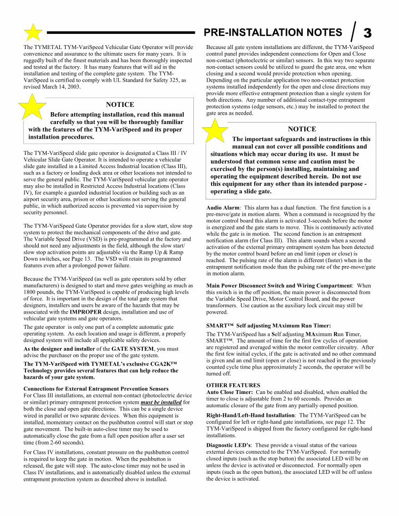
The TYMETAL TYM-VariSpeed Vehicular Gate Operator will provide convenience and assurance to the ultimate users for many years. It is ruggedly built of the finest materials and has been thoroughly inspected and tested at the factory. It has many features that will aid in the installation and testing of the complete gate system. The TYM-VariSpeed is certified to comply with UL Standard for Safety 325, as revised March 14, 2003.
The TYM-VariSpeed slide gate operator is designated a Class III / IV Vehicular Slide Gate Operator. It is intended to operate a vehicular slide gate installed in a Limited Access Industrial location (Class III), such as a factory or loading dock area or other locations not intended to serve the general public. The TYM-VariSpeed vehicular gate operator may also be installed in Restricted Access Industrial locations (Class IV), for example a guarded industrial location or building such as an airport security area, prison or other locations not serving the general public, in which authorized access is prevented via supervision by security personnel.
The TYM-VariSpeed Gate Operator provides for a slow start, slow stop system to protect the mechanical components of the drive and gate. The Variable Speed Drive (VSD) is pre-programmed at the factory and should not need any adjustments in the field, although the slow start/ slow stop activation points are adjustable via the Ramp Up & Ramp Down switches, see Page 13. The VSD will retain its programmed features even after a prolonged power failure.
Because the TYM-VariSpeed (as well as gate operators sold by other manufacturers) is designed to start and move gates weighing as much as 1800 pounds, the TYM-VariSpeed is capable of producing high levels of force. It is important in the design of the total gate system that designers, installers and users be aware of the hazards that may be
associated with the IMPROPER design, installation and use of vehicular gate systems and gate operators.
The gate operator is only one part of a complete automatic gate operating system. As each location and usage is different, a properly designed system will include all applicable safety devices.
As the designer and installer of the GATE SYSTEM, you must advise the purchaser on the proper use of the gate system.
The TYM-VariSpeed with TYMETAL’s exclusive CGA2K™
Technology provides several features that can help reduce the
hazards of your gate system.
Connections for External Entrapment Prevention Sensors For Class III installations, an external non-contact (photoelectric device
or similar) primary entrapment protection system must be installed for both the close and open gate directions. This can be a single device
wired in parallel or two separate devices. When this equipment is
installed, momentary contact on the pushbutton control will start or stop
gate movement. The built-in auto-close timer may be used to
automatically close the gate from a full open position after a user set
time (from 2-60 seconds).
For Class IV installations, constant pressure on the pushbutton control
is required to keep the gate in motion. When the pushbutton is
released, the gate will stop. The auto-close timer may not be used in
Class IV installations, and is automatically disabled unless the external
entrapment protection system as described above is installed.
Because all gate system installations are different, the TYM-VariSpeed control panel provides independent connections for Open and Close non-contact (photoelectric or similar) sensors. In this way two separate non-contact sensors could be utilized to guard the gate area, one when closing and a second would provide protection when opening. Depending on the particular application two non-contact protection systems installed independently for the open and close directions may provide more effective entrapment protection than a single system for both directions. Any number of additional contact-type entrapment protection systems (edge sensors, etc.) may be installed to protect the gate area as needed.
Audio Alarm: This alarm has a dual function. The first function is a pre-move/gate in motion alarm. When a command is recognized by the motor control board this alarm is activated 3-seconds before the motor is energized and the gate starts to move. This is continuously activated while the gate is in motion. The second function is an entrapment notification alarm (for Class III). This alarm sounds when a second activation of the external primary entrapment system has been detected by the motor control board before an end limit (open or close) is reached. The pulsing rate of the alarm is different (faster) when in the entrapment notification mode than the pulsing rate of the pre-move/gate in motion alarm.
Main Power Disconnect Switch and Wiring Compartment: When this switch is in the off position, the main power is disconnected from the Variable Speed Drive, Motor Control Board, and the power transformers. Use caution as the auxiliary lock circuit may still be powered.
SMART™ Self adjusting MAximum Run Timer:
The TYM-VariSpeed has a Self adjusting MAximum Run Timer, SMART™. The amount of time for the first few cycles of operation are registered and averaged within the motor controller circuitry. After the first few initial cycles, if the gate is activated and no other command is given and an end limit (open or close) is not reached in the previously counted cycle time plus approximately 2 seconds, the operator will be turned off.
OTHER FEATURES
Auto Close Timer: Can be enabled and disabled, when enabled the timer to close is adjustable from 2 to 60 seconds. Provides an
automatic closure of the gate from any partially opened position.
Right-Hand/Left-Hand Installation: The TYM-VariSpeed can be configured for left or right-hand gate installations, see page 12. The
TYM-VariSpeed is shipped from the factory configured for right-hand
installations.
Diagnostic LED’s: These provide a visual status of the various external devices connected to the TYM-VariSpeed. For normally
closed inputs (such as the stop button) the associated LED will be on
unless the device is activated or disconnected. For normally open
inputs (such as the open button), the associated LED will be off unless
the device is activated.
NOTICE
Before attempting installation, read this manual
carefully so that you will be thoroughly familiar
with the features of the TYM-VariSpeed and its proper
installation procedures.
NOTICE
The important safeguards and instructions in this
manual can not cover all possible conditions and
situations which may occur during its use. It must be
understood that common sense and caution must be
exercised by the person(s) installing, maintaining and
operating the equipment described herein. Do not use
this equipment for any other than its intended purpose -
operating a slide gate.
PRE-INSTALLATION NOTES 3
GATE SYSTEM DESIGN AND INSTALLATION SAFETY CHECK LIST
• The TYM-VariSpeed operator may be installed on a Class III or IV
Vehicular Slide Gate. See page 3 for an explanation of the different
Class locations.
• Make sure that the gate moves freely, all rollers are in good working
order, the gate does not bind in any manner and the gate area is clean
and free of irregularities. DO NOT INSTALL THE OPERATOR
UNTIL ALL GATE PROBLEMS HAVE BEEN CORRECTED.
• Install the operator on the inside of the property/fence line. DO
NOT install an operator on the public side of the fence line or gate
unless all parts of the drive system will be enclosed and inaccessible.
• Make sure the gate operating system is placed far enough back from the road to eliminate traffic backup. The distance from the road, size of the gate, usage level and gate cycle/speed must be taken into consideration to eliminate potential hazards.
• The gate must be installed in a location so that enough clearance is supplied between the gate and any adjacent structures when opening and closing to reduce the risk of entrapment.
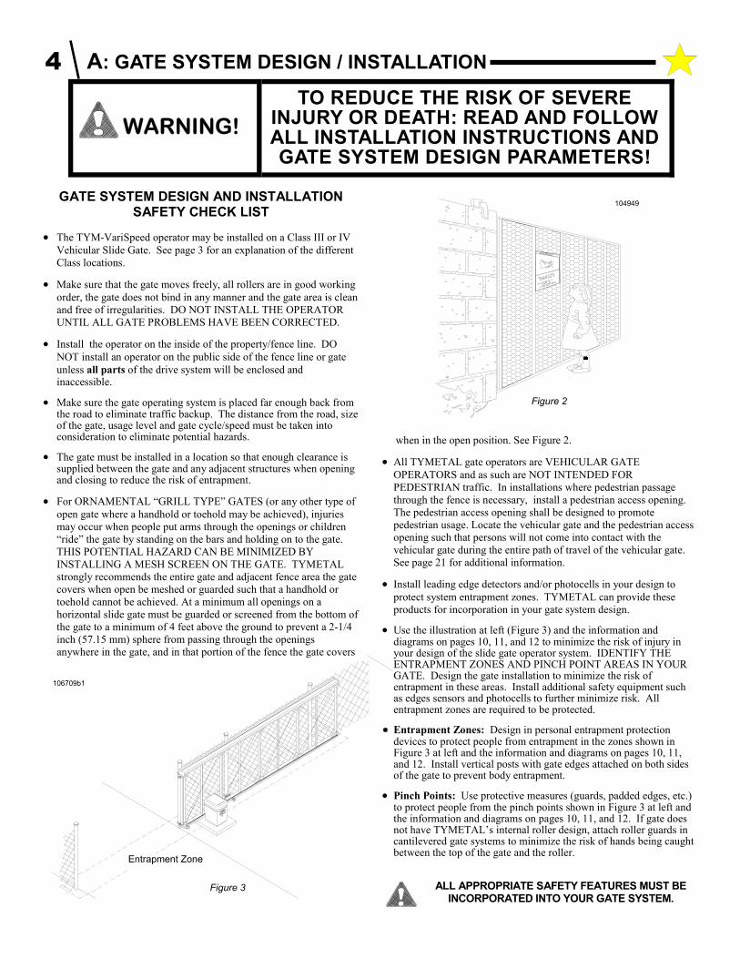
• For ORNAMENTAL “GRILL TYPE” GATES (or any other type of
open gate where a handhold or toehold may be achieved), injuries
may occur when people put arms through the openings or children
“ride” the gate by standing on the bars and holding on to the gate.
THIS POTENTIAL HAZARD CAN BE MINIMIZED BY
INSTALLING A MESH SCREEN ON THE GATE. TYMETAL
strongly recommends the entire gate and adjacent fence area the gate
covers when open be meshed or guarded such that a handhold or
toehold cannot be achieved. At a minimum all openings on a
horizontal slide gate must be guarded or screened from the bottom of
the gate to a minimum of 4 feet above the ground to prevent a 2-1/4
inch (57.15 mm) sphere from passing through the openings
anywhere in the gate, and in that portion of the fence the gate covers
when in the open position. See Figure 2.
• All TYMETAL gate operators are VEHICULAR GATE
OPERATORS and as such are NOT INTENDED FOR
PEDESTRIAN traffic. In installations where pedestrian passage
through the fence is necessary, install a pedestrian access opening.
The pedestrian access opening shall be designed to promote
pedestrian usage. Locate the vehicular gate and the pedestrian access
opening such that persons will not come into contact with the
vehicular gate during the entire path of travel of the vehicular gate.
See page 21 for additional information.
• Install leading edge detectors and/or photocells in your design to
protect system entrapment zones. TYMETAL can provide these
products for incorporation in your gate system design.
• Use the illustration at left (Figure 3) and the information and diagrams on pages 10, 11, and 12 to minimize the risk of injury in your design of the slide gate operator system. IDENTIFY THE ENTRAPMENT ZONES AND PINCH POINT AREAS IN YOUR GATE. Design the gate installation to minimize the risk of entrapment in these areas. Install additional safety equipment such as edges sensors and photocells to further minimize risk. All entrapment zones are required to be protected.
Entrapment Zones: Design in personal entrapment protection devices to protect people from entrapment in the zones shown in Figure 3 at left and the information and diagrams on pages 10, 11, and 12. Install vertical posts with gate edges attached on both sides of the gate to prevent body entrapment.
• Pinch Points: Use protective measures (guards, padded edges, etc.) to protect people from the pinch points shown in Figure 3 at left and the information and diagrams on pages 10, 11, and 12. If gate does not have TYMETAL’s internal roller design, attach roller guards in cantilevered gate systems to minimize the risk of hands being caught between the top of the gate and the roller.
TO REDUCE THE RISK OF SEVERE INJURY OR DEATH: READ AND FOLLOW ALL INSTALLATION INSTRUCTIONS AND GATE SYSTEM DESIGN PARAMETERS!
Figure 2
Figure 3
Entrapment Zone
ALL APPROPRIATE SAFETY FEATURES MUST BE INCORPORATED INTO YOUR GATE SYSTEM.
106709b1
104949
A: GATE SYSTEM DESIGN / INSTALLATION 4

• DO NOT connect any auxiliary equipment to the TYM-VariSpeed
operator (detectors, card readers, etc.) until the gate operator and all
its functions are fully tested. Only connect one device at a time and
ensure its proper function(s) before moving on to the next device.
• DO NOT locate any control device (key switch, switch, key pad,
card reader, etc.) in a position where it may be activated by a person
reaching through the gate or while touching the gate in any manner.
Locate all control devices a minimum of 10 feet from the gate when
opened or closed.
• Outdoor or easily accessible controls must be of the security type to
prevent unauthorized use of the system.
• Install all devices that will Open, Close or Stop the gate in such a
manner that THE GATE WILL BE IN FULL VIEW WHEN THE
DEVICE IS OPERATED.
• Before activating the "timer to close" option of the TYM-VariSpeed,
ENSURE THE PERSONAL ENTRAPMENT PROTECTION
DEVICES (operator reversing feature, edges, photocells) ARE
OPERATING and install VEHICLE DETECTOR LOOPS AND
VEHICLE DETECTORS for protection of user vehicles. Read the
manual for information on the installation of these devices. IF
VEHICLE DETECTOR LOOPS HAVE BEEN INSTALLED TO
PREVENT THE GATE FROM CLOSING ON A VEHICLE,
INSTRUCT THE USER TO PERIODICALLY CHECK THE
OPERATION OF THE DETECTORS.
• USE EXTREME CAUTION WHEN WORKING NEAR THE
INTERNAL MECHANICAL DRIVE COMPONENTS when the
operator cover is removed. Apply power to the operator only when
instructed to do so.
• When the cover of the TYM-VariSpeed Control Box cover is
removed, high voltage will be exposed. EVEN IF THE RED
POWER LIGHT IS NOT LIGHTED, HIGH VOLTAGE AC MAY
STILL BE PRESENT. NEVER LEAVE THE INSTALLATION
WITH THE CONTROL BOX COVER REMOVED.
• ALWAYS TURN OFF THE POWER AT THE DISCONNECT
SWITCH BEFORE ATTEMPTING SERVICE OF EITHER THE
ELECTRICAL OR MECHANICAL SYSTEMS. ALLOW A
WAITING PERIOD BEFORE REMOVING THE CONTROL BOX
COVER AS HIGH VOLTAGE AC WILL STILL BE PRESENT
INSIDE THE CONTROL BOX FOR APPROX. TWO MINUTES
AFTER THE POWER IS REMOVED.
• SECURELY ATTACH THE WARNING SIGNS provided with the
TYM-VariSpeed on the gate (one on the outside and one on the
inside) where they can be seen by persons in the area of the gate to
alert them of automatic gate operation. (If the user refuses to have
the warning signs installed, TYMETAL recommends that you note
this on your records and have the user sign a disclaimer.) See Figure
4.
AS THE INSTALLER YOU ARE RESPONSIBLE FOR:
1 ASSURING THAT THE GATE AND OPERATOR SYSTEM,
WHEN FULLY INSTALLED AND OPERABLE, COMPLIES
WITH ALL APPLICABLE REQUIREMENTS OF UL325:
STANDARD FOR SAFETY FOR DOOR, DRAPERY, GATE,
LOUVER AND WINDOW OPERATORS AND SYSTEMS.
2 ASSURING THAT THE OWNER/END USER OF THE
SYSTEM UNDERSTANDS ITS BASIC OPERATION AND
SAFETY FEATURES. IN PARTICULAR, BE SURE THE
OWNER/END USER UNDERSTANDS THE LOCATION
AND OPERATION OF A MANUAL DISCONNECT
(WHERE PROVIDED) OR HOW TO OPERATE THE GATE
MANUALLY.
3 YOU ALSO HAVE THE PRIMARY RESPONSIBILITY OF
INSURING THAT ALL POSSIBLE OPERATIONAL
HAZARDS HAVE BEEN CONSIDERED AND
ELIMINATED. YOU MUST ADVISE AND WARN THE
PURCHASER AND THE ULTIMATE USER OF ANY
HAZARDS THAT YOU HAVE NOT BEEN ABLE TO
ELIMINATE.
4 POINTING OUT TO THE OWNER/END USER OF THE
GATE SYSTEM THAT CHILDREN OR PETS ARE NOT
ALLOWED TO PLAY ON OR NEAR THE GATE, FENCE
OR ANY PART OF THE SYSTEM, AND THAT THE
SAFETY INSTRUCTIONS SUPPLIED WITH THIS
OPERATOR AND THEIR IMPLEMENTATION ARE THE
RESPONSIBILITY OF THE OWNER/END USER.
5 LEAVING THE INSTALLATION AND MAINTENANCE
MANUAL FOR THIS OPERATOR AS WELL AS ANY
ADDITIONAL SAFETY INFORMATION SUPPLIED WITH
THIS OPERATOR OR OTHER COMPONENTS OF THE
GATE SYSTEM WITH THE OWNER/END USER.
6 NOT PLACING IN SERVICE THIS OPERATOR IF YOU
HAVE ANY QUESTIONS ABOUT THE SAFETY OF THE
GATE OPERATING SYSTEM. CONSULT THE
OPERATOR MANUFACTURER.
DEATH
area is in sight and free ofpeople and obstructions.
Gate May Move at Any Time.Do not allow children to playin gate area or operate gate.Operate gate only when gate
KEEP CLEAR !
CAN CAUSESERIOUS
INJURY OR
MOVING GATE
Figure 4
A: GATE SYSTEM DESIGN & INSTALLATION 5
ELECTRICAL POWER REQUIREMENTS
NOTE: Before connecting the operator, use a voltmeter to
insure that the electrical service is applicable according to the
product label. Connection to the improper voltage and/or phase is
the most common cause of unit failure in new installations and is
NOT covered by the warranty.
In installations with more than one operator, each operator must have a
separate service from the breaker panel. The electrical hookup is made
in the junction box located in the upper right front corner of the control
panel.
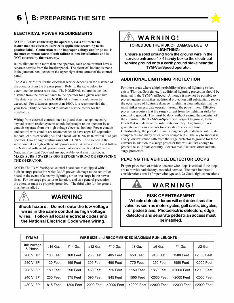
The AWG wire size for the electrical service depends on the distance of
the operator from the breaker panel. Refer to the table below to
determine the correct wire size. The NOMINAL column is the ideal
distance from the breaker panel to the operator for a given wire size.
The distances shown in the NOMINAL column should never be
exceeded. For distances greater than 1600', it is recommended that
your local utility be contacted to install a service feeder for the
installation.
Wiring from external controls such as guard shack, telephone entry,
keypad or card reader systems should be brought to the operator by a
conduit separate from the high voltage electrical hookup. Power conduit
and control wire conduit are recommended to have appx 18" separation
for parallel runs exceeding 50' and a local GROUND ROD within 3' of gate
operator. Low voltage control wires MUST NEVER be routed in the
same conduit as high voltage AC power wires. Always consult and follow
the National voltage AC power wires. Always consult and follow the
National Electrical Code and any applicable local electrical codes.
MAKE SURE POWER IS OFF BEFORE WIRING OR SERVICING
THE OPERATOR.
NOTE: The TYM-VariSpeed control board comes equipped with a
built-in surge protection which MAY prevent damage to the controller
board in the event of a nearby lightning strike or a surge in the power
lines. For the surge protector to function, and as a general precaution,
the operator must be properly grounded. The third wire for the ground
must be installed .
ADDITIONAL LIGHTNING PROTECTION
For those areas where a high probability of ground lightning strikes
exists (Florida, Georgia, etc.), additional lightning protection should be
installed in the TYM-VariSpeed. Although it may not be possible to
protect against all strikes, additional protection will substantially reduce
the occurrence of lightning damage. Lightning data indicates that the
most strikes enter a gate operator through the power lines. Effective
protection requires that the surge current from the lightning strike be
shunted to ground. This must be done without raising the potential of
the circuitry in the TYM-VariSpeed, with respect to ground, to the
levels that will damage the solid state circuitry. Lightning strikes
generate enormous currents for very short periods of time.
Unfortunately, the period of time is long enough to damage solid state
components and many times, other components. The key to success is
a very low resistance path from the surge protector to ground for these
currents in addition to a surge protector that will act fast enough to
protect the solid state circuitry. Several manufacturers offer suitable
surge protectors.
PLACING THE VEHICLE DETECTOR LOOPS
Proper placement of vehicle detector wire loops is critical if the loops
are to provide satisfactory, extended service. The most important
considerations are: 1) Proper wire type and, 2) Good, tight connections
WARNING
Shock hazard: Do not route the low voltage wires in the same conduit as high voltage
wires. Follow all local electrical codes and the National Electrical Code when wiring.
RISK OF ENTRAPMENT Vehicle detector loops will not detect smaller
vehicles such as motorcycles, golf carts, bicycles, or pedestrians. Photoelectric detectors, edge
detectors and separate pedestrian access must be installed.
W A R N I N G !
W A R N I N G ! TO REDUCE THE RISK OF DAMAGE DUE TO
LIGHTNING:Ensure a solid ground from the ground wire in the service entrance 4 x 4 handy box to the electrical
service ground or to a earth ground stake near the TYM-VariSpeed operator.
TYM-VS WIRE SIZE and RECOMMENDED MAXIMUM RUN LENGHTS
Unit Voltage & Phase
#16 Ga. #14 Ga. #12 Ga. #10 Ga. #8 Ga. #6 Ga. #4 Ga. #2 Ga.
208 V, 1P 100 Feet 160 Feet 255 Feet 405 Feet 650 Feet 945 Feet 1500 Feet >2000 Feet
240 V, 1P 120 Feet 195 Feet 305 Feet 490 Feet 775 Feet 1250 Feet 1950 Feet >2000 Feet
208 V, 3P 180 Feet 290 Feet 460 Feet 725 Feet 1150 Feet 1850 Feet >2000 Feet >2000 Feet
240 V, 3P 230 Feet 375 Feet 595 Feet 945 Feet 1500 Feet >2000 Feet >2000 Feet >2000 Feet
480 V, 3P 815 Feet 1300 Feet 2000 Feet >2000 Feet >2000 Feet >2000 Feet >2000 Feet >2000 Feet
B: PREPARING THE SITE 6
from the loop to the loop terminating connector. When a "Stand
Alone" vehicle detector is used, the detection loop is connected to the
wire harness on the detector itself.
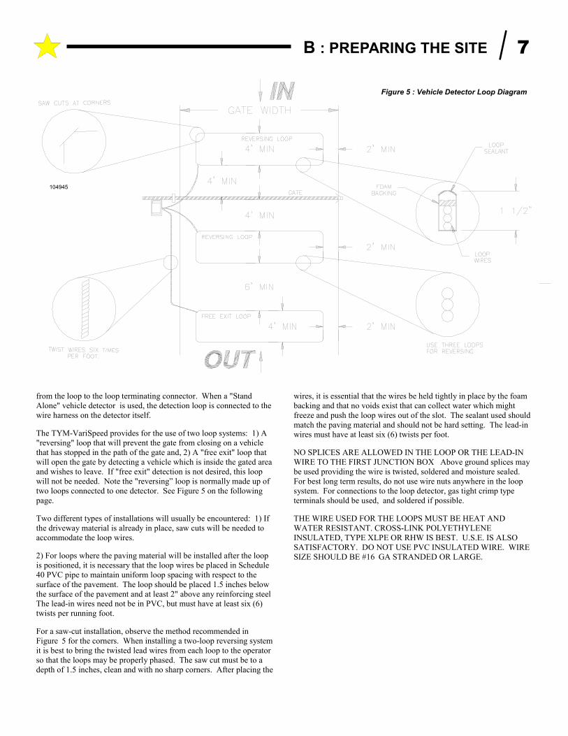
The TYM-VariSpeed provides for the use of two loop systems: 1) A
"reversing" loop that will prevent the gate from closing on a vehicle
that has stopped in the path of the gate and, 2) A "free exit" loop that
will open the gate by detecting a vehicle which is inside the gated area
and wishes to leave. If "free exit" detection is not desired, this loop
will not be needed. Note the "reversing” loop is normally made up of
two loops connected to one detector. See Figure 5 on the following
page.
Two different types of installations will usually be encountered: 1) If
the driveway material is already in place, saw cuts will be needed to
accommodate the loop wires.
2) For loops where the paving material will be installed after the loop
is positioned, it is necessary that the loop wires be placed in Schedule
40 PVC pipe to maintain uniform loop spacing with respect to the
surface of the pavement. The loop should be placed 1.5 inches below
the surface of the pavement and at least 2" above any reinforcing steel
The lead-in wires need not be in PVC, but must have at least six (6)
twists per running foot.
For a saw-cut installation, observe the method recommended in
Figurez5 for the corners. When installing a two-loop reversing system
it is best to bring the twisted lead wires from each loop to the operator
so that the loops may be properly phased. The saw cut must be to a
depth of 1.5 inches, clean and with no sharp corners. After placing the
wires, it is essential that the wires be held tightly in place by the foam
backing and that no voids exist that can collect water which might
freeze and push the loop wires out of the slot. The sealant used should
match the paving material and should not be hard setting. The lead-in
wires must have at least six (6) twists per foot.
NO SPLICES ARE ALLOWED IN THE LOOP OR THE LEAD-IN
WIRE TO THE FIRST JUNCTION BOX Above ground splices may
be used providing the wire is twisted, soldered and moisture sealed.
For best long term results, do not use wire nuts anywhere in the loop
system. For connections to the loop detector, gas tight crimp type
terminals should be used, and soldered if possible.
THE WIRE USED FOR THE LOOPS MUST BE HEAT AND
WATER RESISTANT. CROSS-LINK POLYETHYLENE
INSULATED, TYPE XLPE OR RHW IS BEST. U.S.E. IS ALSO
SATISFACTORY. DO NOT USE PVC INSULATED WIRE. WIRE
SIZE SHOULD BE #16zGA STRANDED OR LARGE.
Figure 5 : Vehicle Detector Loop Diagram
104945
B : PREPARING THE SITE 7
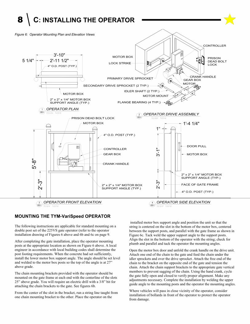
MOUNTING THE TYM-VariSpeed OPERATOR The following instructions are applicable for standard mounting on a
double post set of the 225VS gate operator (refer to the operator
installation drawing of Figures 6 above and 6b and 6c on page 9.
After completing the gate installation, place the operator mounting
posts at the appropriate location as shown on Figure 6 above. A local
engineer in accordance with local building codes shall determine the
post footing requirements. When the concrete had set sufficiently,
install the lower motor box support angle. The angle should be set level
and welded to the motor box posts so the top of the angle is at 27”
above grade.
The chain mounting brackets provided with the operator should be
mounted on the gate frame at each end with the centerline of the slots
25” above grade. You will require an electric drill with a 3/8” bit for
attaching the chain brackets to the gate. See figures 6b.
From the center of the slot in the bracket, run a string line taught from
one chain mounting bracket to the other. Place the operator on the
installed motor box support angle and position the unit so that the
string is centered on the slot in the bottom of the motor box, centered
between the support posts, and parallel with the gate frame as shown in
Figure 6c. Tack weld the upper support angle to the support posts.
Align the slot in the bottom of the operator with the string; check for
plumb and parallel and tack the operator the mounting angles.
Open the motor box door and unfold the crank handle on the drive unit.
Attach one end of the chain to the gate and feed the chain under the
idler sprockets and over the drive sprocket. Attach the free end of the
chain to the bracket on the opposite end of the gate and tension the
chain. Attach the chain support brackets to the appropriate gate vertical
members to prevent sagging of the chain. Using the hand crank, cycle
the gate fully open and closed to verify proper alignment. Make any
adjustments necessary. Complete the installation by welding the upper
guide angle to the mounting posts and the operator the mounting angles.
Where vehicles will pass in close vicinity of the operator, consider
installation of bollards in front of the operator to protect the operator
from damage.
5'-8
"2
'-3
"
1"1'-4 1/4"
2'-3
"3
'-1"
3'-10"
2'-11 1/2"5 1/4"
1
2
43
Figure 6: Operator Mounting Plan and Elevation Views
8 C: INSTALLING THE OPERATOR
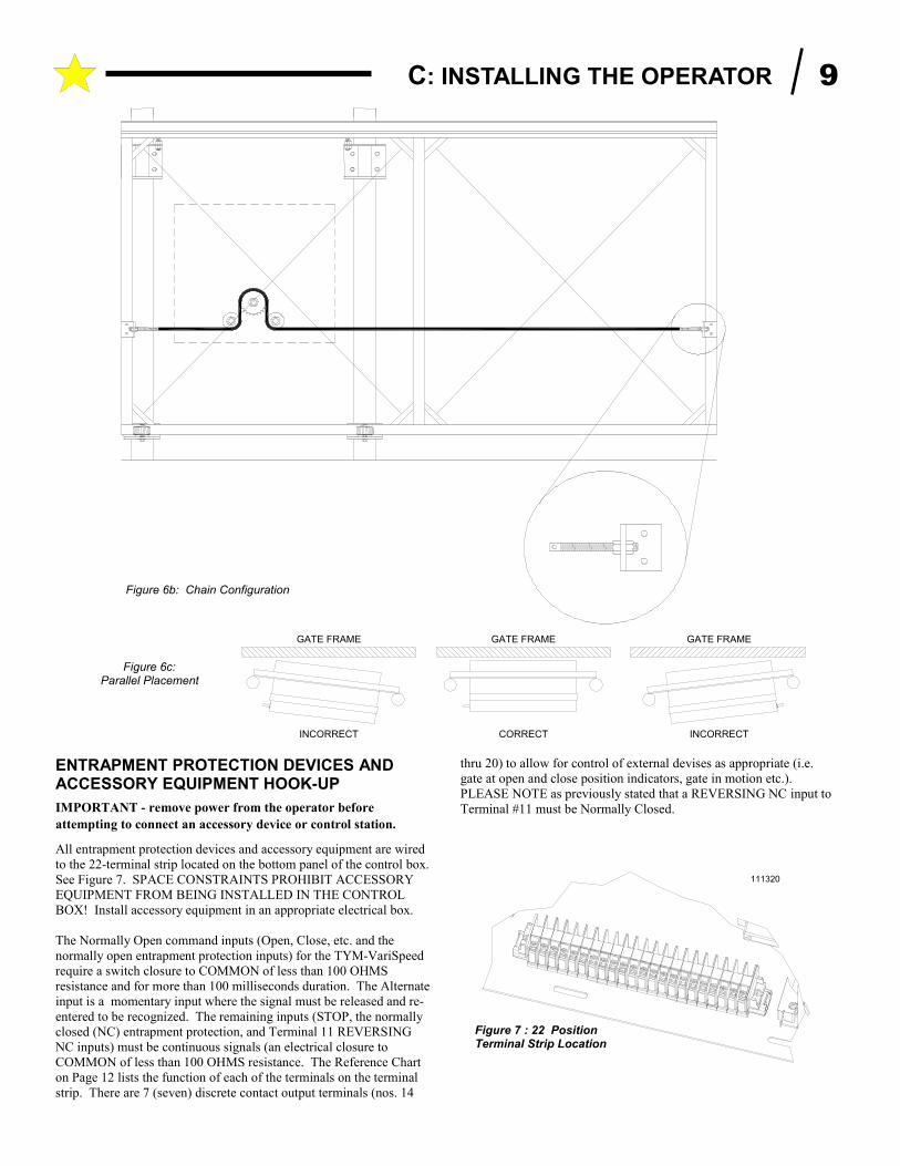
ENTRAPMENT PROTECTION DEVICES AND ACCESSORY EQUIPMENT HOOK-UP
IMPORTANT - remove power from the operator before
attempting to connect an accessory device or control station.
All entrapment protection devices and accessory equipment are wired
to the 22-terminal strip located on the bottom panel of the control box.
See Figure 7. SPACE CONSTRAINTS PROHIBIT ACCESSORY
EQUIPMENT FROM BEING INSTALLED IN THE CONTROL
BOX! Install accessory equipment in an appropriate electrical box.
The Normally Open command inputs (Open, Close, etc. and the
normally open entrapment protection inputs) for the TYM-VariSpeed
require a switch closure to COMMON of less than 100 OHMS
resistance and for more than 100 milliseconds duration. The Alternate
input is a momentary input where the signal must be released and re-
entered to be recognized. The remaining inputs (STOP, the normally
closed (NC) entrapment protection, and Terminal 11 REVERSING
NC inputs) must be continuous signals (an electrical closure to
COMMON of less than 100 OHMS resistance. The Reference Chart
on Page 12 lists the function of each of the terminals on the terminal
strip. There are 7 (seven) discrete contact output terminals (nos. 14
thru 20) to allow for control of external devises as appropriate (i.e.
gate at open and close position indicators, gate in motion etc.).
PLEASE NOTE as previously stated that a REVERSING NC input to
Terminal #11 must be Normally Closed.
111320
Figure 7 : 22 Position Terminal Strip Location
Figure 6b: Chain Configuration
GATE FRAME
CORRECTINCORRECT
GATE FRAME
INCORRECT
GATE FRAME
Figure 6c: Parallel Placement
C: INSTALLING THE OPERATOR 9
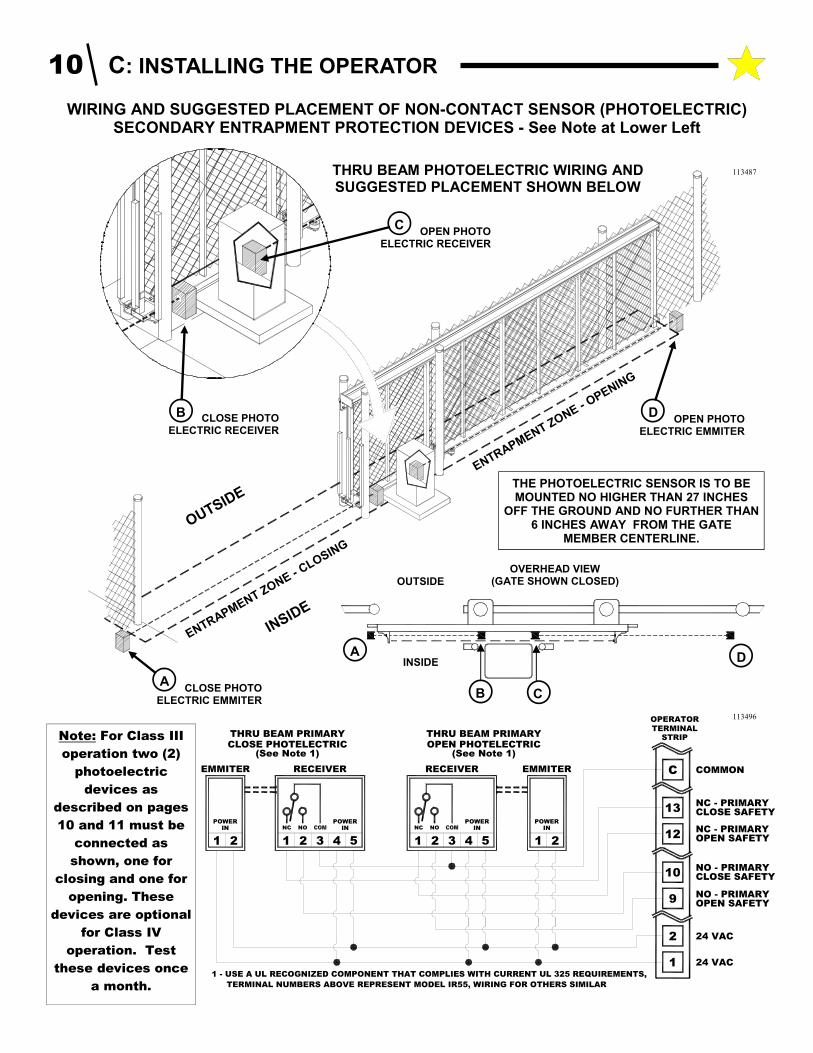
WIRING AND SUGGESTED PLACEMENT OF NON-CONTACT SENSOR (PHOTOELECTRIC) SECONDARY ENTRAPMENT PROTECTION DEVICES - See Note at Lower Left
OUTSIDE
INSID
E
ENTRAPMENT ZONE - CLOSIN
G
ENTRAPMENT ZONE - OPENIN
G
D OPEN PHOTO
ELECTRIC EMMITER
A CLOSE PHOTO
ELECTRIC EMMITER
OUTSIDE
INSIDE A
B C
D
OVERHEAD VIEW (GATE SHOWN CLOSED)
CLOSE PHOTO ELECTRIC RECEIVER
B
OPEN PHOTO ELECTRIC RECEIVER
C
THRU BEAM PHOTOELECTRIC WIRING AND SUGGESTED PLACEMENT SHOWN BELOW
THE PHOTOELECTRIC SENSOR IS TO BE MOUNTED NO HIGHER THAN 27 INCHES
OFF THE GROUND AND NO FURTHER THAN 6 INCHES AWAY FROM THE GATE
MEMBER CENTERLINE.
113487
C
5
1
COMMON
24 VAC
24 VAC
TERMINALSTRIP
13
OPEN PHOTELECTRIC
321
NC NO
4
INPOWER
12NC - PRIMARY
2
POWERIN
1 2
EMMITERRECEIVERRECEIVEREMMITER
21
INPOWER POWER
IN
4
NONC
1 2 3
CLOSE PHOTELECTRIC
5
OPERATOR
THRU BEAM PRIMARYTHRU BEAM PRIMARY
OPEN SAFETY
1 - USE A UL RECOGNIZED COMPONENT THAT COMPLIES WITH CURRENT UL 325 REQUIREMENTS,
TERMINAL NUMBERS ABOVE REPRESENT MODEL IR55, WIRING FOR OTHERS SIMILAR
(See Note 1) (See Note 1)
NC - PRIMARYCLOSE SAFETY
OPEN SAFETY
CLOSE SAFETY
9 NO - PRIMARY
NO - PRIMARY10
Note: For Class III
operation two (2)
photoelectric
devices as
described on pages
10 and 11 must be
connected as
shown, one for
closing and one for
opening. These
devices are optional
for Class IV
operation. Test
these devices once
a month.
113496
10 C: INSTALLING THE OPERATOR
OVERHEAD VIEW (GATE SHOWN CLOSED)
OUTSIDE
INSIDE A
B C
D
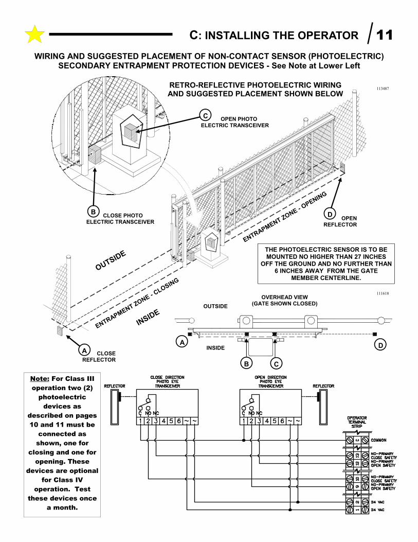
WIRING AND SUGGESTED PLACEMENT OF NON-CONTACT SENSOR (PHOTOELECTRIC) SECONDARY ENTRAPMENT PROTECTION DEVICES - See Note at Lower Left
OUTSIDE
INSID
E
ENTRAPMENT ZONE- CLOSIN
G
ENTRAPMENT ZONE- OPENIN
G
A CLOSE REFLECTOR
CLOSE PHOTO ELECTRIC TRANSCEIVER
B
OPEN PHOTO ELECTRIC TRANSCEIVER
C
RETRO-REFLECTIVE PHOTOELECTRIC WIRING AND SUGGESTED PLACEMENT SHOWN BELOW
DOPEN
REFLECTOR
THE PHOTOELECTRIC SENSOR IS TO BE MOUNTED NO HIGHER THAN 27 INCHES
OFF THE GROUND AND NO FURTHER THAN 6 INCHES AWAY FROM THE GATE
MEMBER CENTERLINE.
113487
111618
Note: For Class III
operation two (2)
photoelectric
devices as
described on pages
10 and 11 must be
connected as
shown, one for
closing and one for
opening. These
devices are optional
for Class IV
operation. Test
these devices once
a month.
C: INSTALLING THE OPERATOR 11
OUTSIDE
INSIDE
B
OVERHEAD VIEW (GATE SHOWN CLOSED)
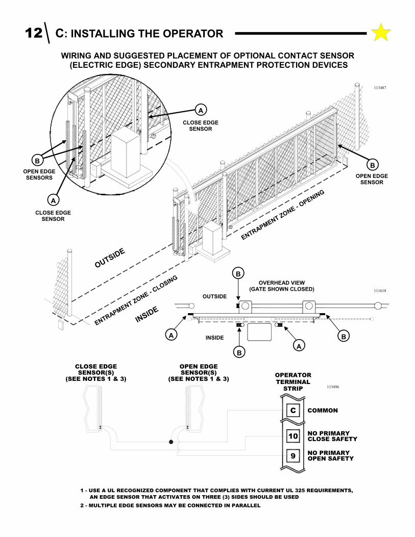
WIRING AND SUGGESTED PLACEMENT OF OPTIONAL CONTACT SENSOR (ELECTRIC EDGE) SECONDARY ENTRAPMENT PROTECTION DEVICES
OUTSIDE
INSID
E
ENTRAPMENT ZONE - CLOSIN
G
ENTRAPMENT ZONE - OPENIN
G
B
OPEN EDGE SENSOR
A
CLOSE EDGE SENSOR
B
OPEN EDGE SENSORS
A
CLOSE EDGE SENSOR
A
B
A
B
113487
111618
C COMMON
TERMINALSTRIP
10
9NO PRIMARY
NO PRIMARY
CLOSE EDGE
OPERATOR
OPEN SAFETY
CLOSE SAFETY
1 - USE A UL RECOGNIZED COMPONENT THAT COMPLIES WITH CURRENT UL 325 REQUIREMENTS,
AN EDGE SENSOR THAT ACTIVATES ON THREE (3) SIDES SHOULD BE USED
2 - MULTIPLE EDGE SENSORS MAY BE CONNECTED IN PARALLEL
SENSOR(S) SENSOR(S)OPEN EDGE
(SEE NOTES 1 & 3)(SEE NOTES 1 & 3)
113496
12 C: INSTALLING THE OPERATOR
WIRING THE VEHICLE DETECTOR(S) TO THE GATE OPERATOR
NOTE: INSTALLATION STEPS DETAILED IN SECTIONS
A, B, C AND D MUST BE COMPLETE BEFORE WIRING IN
THE VEHICLE LOOP DETECTOR(S). The wiring
instructions are placed here for sake of continuity with the
subject matter.
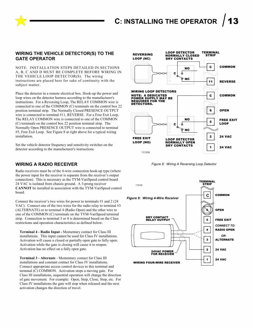
Place the detector in a remote electrical box. Hook-up the power and
loop wires on the detector harness according to the manufacturer's
instructions. For a Reversing Loop, The RELAY COMMON wire is
connected to one of the COMMON (C) terminals on the control box 22
position terminal strip. The Normally Closed PRESENCE OUTPUT
wire is connected to terminal #11, REVERSE. For a Free Exit Loop,
The RELAY COMMON wire is connected to one of the COMMON
(C) terminals on the control box 22 position terminal strip. The
Normally Open PRESENCE OUTPUT wire is connected to terminal
#5, Free Exit Loop. See Figure 8 at right above for a typical wiring
installation.
Set the vehicle detector frequency and sensitivity switches on the
detector according to the manufacturer's instructions.
WIRING A RADIO RECEIVER
Radio receivers must be of the 4-wire connection hook-up type (where
the power input for the receiver is separate from the receiver’s output
connection). This is necessary as the TYM-VariSpeed control board
24 VAC is isolated from chassis ground. A 3-prong receiver
CANNOT be installed in association with the TYM-VariSpeed control board.
Connect the receiver’s two wires for power to terminals #1 and 2 (24
VAC). Connect one of the two wires for the radio relay to terminal #3
(ALTERNATE) or to terminal 4 (Radio Open) and the other wire to
one of the COMMON (C) terminals on the TYM-VariSpeed terminal
strip. Connection to terminal 3 or 4 is determined based on the Class
restrictions and operation characteristics as defined below:
Terminal 4 - Radio Input - Momentary contact for Class III installations. This input cannot be used for Class IV installations.
Activation will cause a closed or partially open gate to fully open.
Activation while the gate is closing will cause it to reopen.
Activation has no effect on a fully open gate.
Terminal 3 - Alternate - Momentary contact for Class III installations and constant contact for Class IV installations.
Connect appropriate access control devices to this terminal and
terminal (C) COMMON. Activation stops a moving gate. For
Class III installations, sequential operation will change the direction
of gate movement. For example: Open, Stop, Close, Stop, etc. For
Class IV installations the gate will stop when released and the next
activation changes the direction of travel.
Figure 8: Wiring A Reversing Loop Detector
TERMINAL
REQUIRED FOR THE
LOOP (NO)
DETECTORS.
FREE EXIT
NORMALLY OPENDRY CONTACTS
1
LOOP DETECTOR
NO
NC
C5
2
6
NOTE: A DEDICATEDPOWER SUPPLY MAY BE
WIRING LOOP DETECTORS
REVERSING
LOOP (NC)
NO
NC
C
11
C
C
NORMALLY CLOSEDDRY CONTACTS
LOOP DETECTORSTRIP
24 VAC
FREE EXIT
LOOP
24 VAC
OPEN
REVERSE
COMMON
COMMON
111316
16
4
2
1
COMMON
RADIO OPEN
24 VAC
24 VACWIRING FOUR-WIRE RECEIVER
TERMINALSTRIP
ALTERNATE3
FREE EXIT5
OPEN6
DRY CONTACTRELAY OUTPUT
24VAC POWERFOR RECEIVER
110120
CONNECT TO:
OR:
Figure 9: Wiring 4-Wire Receiver C
C: INSTALLING THE OPERATOR 13
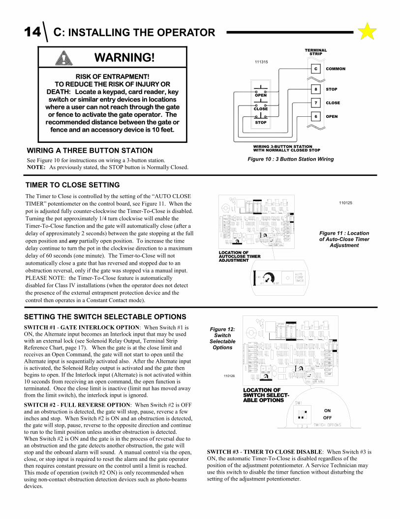
SETTING THE SWITCH SELECTABLE OPTIONS
SWITCH #1 - GATE INTERLOCK OPTION: When Switch #1 is ON, the Alternate input becomes an Interlock input that may be used
with an external lock (see Solenoid Relay Output, Terminal Strip
Reference Chart, page 17). When the gate is at the close limit and
receives an Open Command, the gate will not start to open until the
Alternate input is sequentially activated also. After the Alternate input
is activated, the Solenoid Relay output is activated and the gate then
begins to open. If the Interlock input (Alternate) is not activated within
10 seconds from receiving an open command, the open function is
terminated. Once the close limit is inactive (limit nut has moved away
from the limit switch), the interlock input is ignored.
SWITCH #2 - FULL REVERSE OPTION: When Switch #2 is OFF and an obstruction is detected, the gate will stop, pause, reverse a few
inches and stop. When Switch #2 is ON and an obstruction is detected,
the gate will stop, pause, reverse to the opposite direction and continue
to run to the limit position unless another obstruction is detected.
When Switch #2 is ON and the gate is in the process of reversal due to
an obstruction and the gate detects another obstruction, the gate will
stop and the onboard alarm will sound. A manual control via the open,
close, or stop input is required to reset the alarm and the gate operator
then requires constant pressure on the control until a limit is reached.
This mode of operation (switch #2 ON) is only recommended when
using non-contact obstruction detection devices such as photo-beams
devices.
SWITCH #3 - TIMER TO CLOSE DISABLE: When Switch #3 is ON, the automatic Timer-To-Close is disabled regardless of the
position of the adjustment potentiometer. A Service Technician may
use this switch to disable the timer function without disturbing the
setting of the adjustment potentiometer.
TIMER TO CLOSE SETTING
The Timer to Close is controlled by the setting of the “AUTO CLOSE
TIMER” potentiometer on the control board, see Figure 11. When the
pot is adjusted fully counter-clockwise the Timer-To-Close is disabled.
Turning the pot approximately 1/4 turn clockwise will enable the
Timer-To-Close function and the gate will automatically close (after a
delay of approximately 2 seconds) between the gate stopping at the full
open position and any partially open position. To increase the time
delay continue to turn the pot in the clockwise direction to a maximum
delay of 60 seconds (one minute). The Timer-to-Close will not
automatically close a gate that has reversed and stopped due to an
obstruction reversal, only if the gate was stopped via a manual input.
PLEASE NOTE: the Timer-To-Close feature is automatically
disabled for Class IV installations (when the operator does not detect
the presence of the external entrapment protection device and the
control then operates in a Constant Contact mode).
ADJUSTMENTAUTOCLOSE TIMERLOCATION OF
Figure 11 : Location of Auto-Close Timer
Adjustment
110125
WITH NORMALLY CLOSED STOPWIRING 3-BUTTON STATION
STOP
CLOSE
OPEN
CLOSE7
OPEN6
STOP
COMMON
8
C
STRIPTERMINAL
111315
Figure 10 : 3 Button Station Wiring
WIRING A THREE BUTTON STATION
See Figure 10 for instructions on wiring a 3-button station.
NOTE: As previously stated, the STOP button is Normally Closed.
ABLE OPTIONSSWITCH SELECT-LOCATION OF
110126
ON
OFF
Figure 12: Switch
Selectable Options
14 C: INSTALLING THE OPERATOR
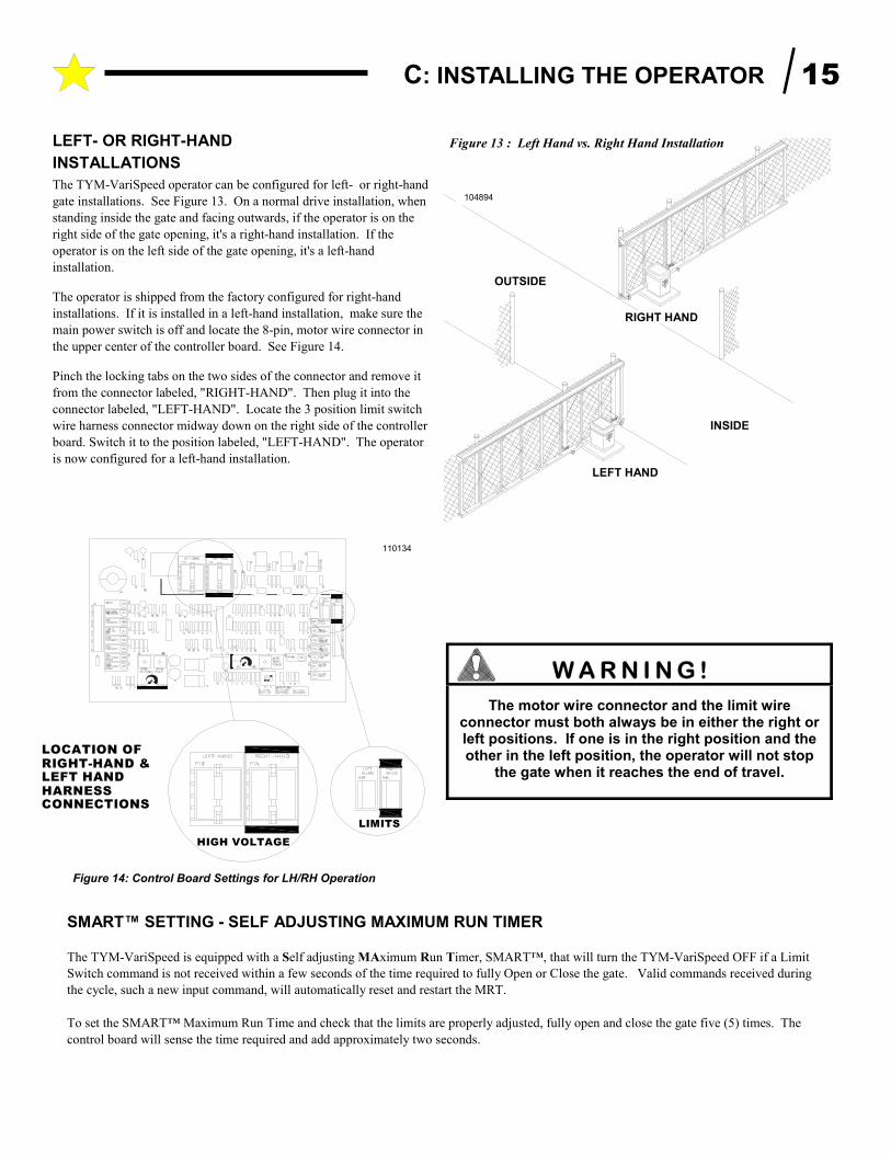
LEFT- OR RIGHT-HAND
INSTALLATIONS
The TYM-VariSpeed operator can be configured for left- or right-hand
gate installations. See Figure 13. On a normal drive installation, when
standing inside the gate and facing outwards, if the operator is on the
right side of the gate opening, it's a right-hand installation. If the
operator is on the left side of the gate opening, it's a left-hand
installation.
The operator is shipped from the factory configured for right-hand
installations. If it is installed in a left-hand installation, make sure the
main power switch is off and locate the 8-pin, motor wire connector in
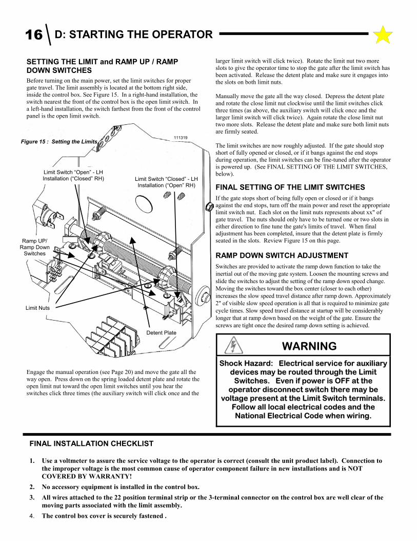
the upper center of the controller board. See Figure 14.
Pinch the locking tabs on the two sides of the connector and remove it
from the connector labeled, "RIGHT-HAND". Then plug it into the
connector labeled, "LEFT-HAND". Locate the 3 position limit switch
wire harness connector midway down on the right side of the controller
board. Switch it to the position labeled, "LEFT-HAND". The operator
is now configured for a left-hand installation.
HIGH VOLTAGE
HARNESSCONNECTIONS
LEFT HANDRIGHT-HAND &LOCATION OF
LIMITS
110134
SMART™ SETTING - SELF ADJUSTING MAXIMUM RUN TIMER
The TYM-VariSpeed is equipped with a Self adjusting MAximum Run Timer, SMART™, that will turn the TYM-VariSpeed OFF if a Limit
Switch command is not received within a few seconds of the time required to fully Open or Close the gate. Valid commands received during
the cycle, such a new input command, will automatically reset and restart the MRT.
To set the SMART™ Maximum Run Time and check that the limits are properly adjusted, fully open and close the gate five (5) times. The
control board will sense the time required and add approximately two seconds.
OUTSIDE
Figure 13 : Left Hand vs. Right Hand Installation
104894
LEFT HAND
INSIDE
RIGHT HAND
The motor wire connector and the limit wire connector must both always be in either the right or left positions. If one is in the right position and the other in the left position, the operator will not stop
the gate when it reaches the end of travel.
Figure 14: Control Board Settings for LH/RH Operation
C: INSTALLING THE OPERATOR 15
FINAL INSTALLATION CHECKLIST
1. Use a voltmeter to assure the service voltage to the operator is correct (consult the unit product label). Connection to
the improper voltage is the most common cause of operator component failure in new installations and is NOT
COVERED BY WARRANTY!
2. No accessory equipment is installed in the control box.
3. All wires attached to the 22 position terminal strip or the 3-terminal connector on the control box are well clear of the
moving parts associated with the limit assembly.
4. The control box cover is securely fastened .
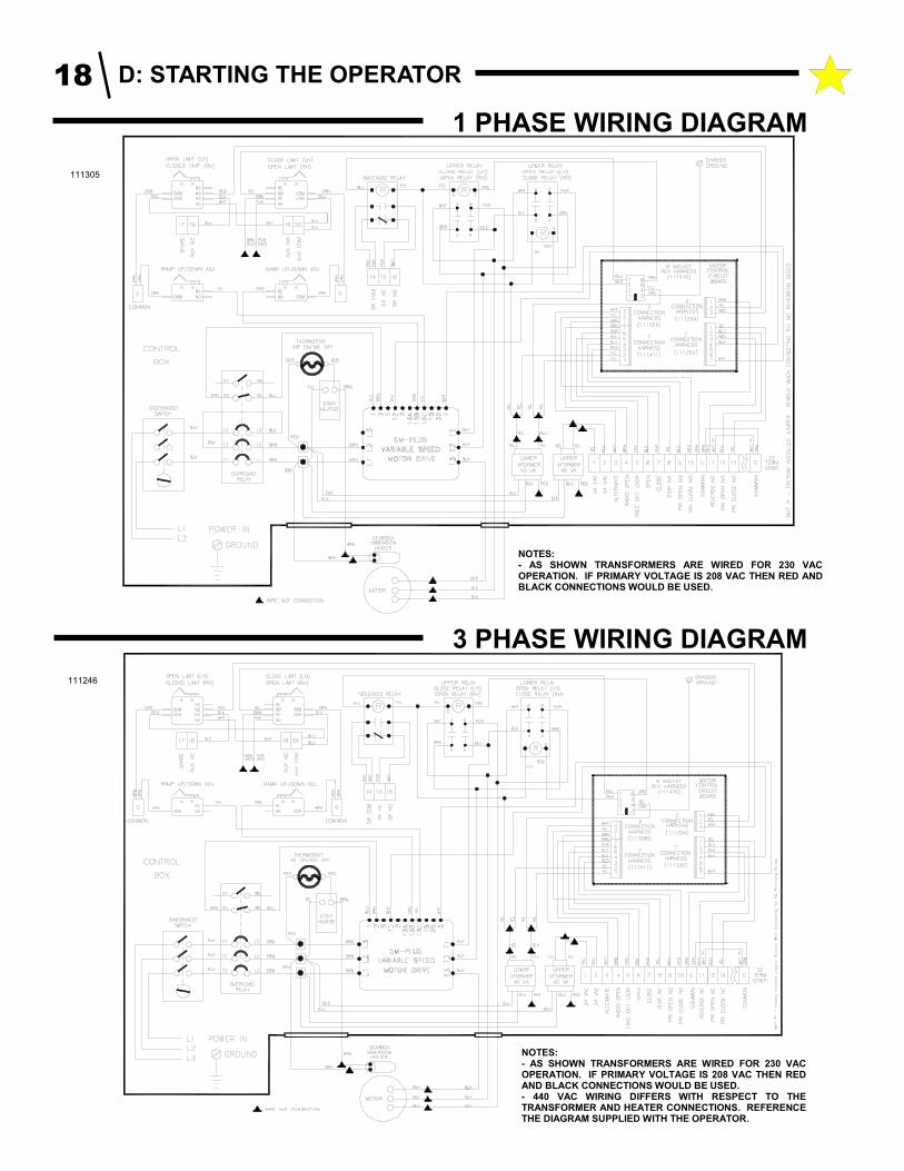
SETTING THE LIMIT and RAMP UP / RAMP DOWN SWITCHES
Before turning on the main power, set the limit switches for proper
gate travel. The limit assembly is located at the bottom right side,
inside the control box. See Figure 15. In a right-hand installation, the
switch nearest the front of the control box is the open limit switch. In
a left-hand installation, the switch farthest from the front of the control
panel is the open limit switch.
Engage the manual operation (see Page 20) and move the gate all the
way open. Press down on the spring loaded detent plate and rotate the
open limit nut toward the open limit switches until you hear the
switches click three times (the auxiliary switch will click once and the
larger limit switch will click twice). Rotate the limit nut two more
slots to give the operator time to stop the gate after the limit switch has
been activated. Release the detent plate and make sure it engages into
the slots on both limit nuts.
Manually move the gate all the way closed. Depress the detent plate
and rotate the close limit nut clockwise until the limit switches click
three times (as above, the auxiliary switch will click once and the
larger limit switch will click twice). Again rotate the close limit nut
two more slots. Release the detent plate and make sure both limit nuts
are firmly seated.
The limit switches are now roughly adjusted. If the gate should stop
short of fully opened or closed, or if it bangs against the end stops
during operation, the limit switches can be fine-tuned after the operator
is powered up. (See FINAL SETTING OF THE LIMIT SWITCHES,
below).
FINAL SETTING OF THE LIMIT SWITCHES
If the gate stops short of being fully open or closed or if it bangs
against the end stops, turn off the main power and reset the appropriate
limit switch nut. Each slot on the limit nuts represents about xx" of
gate travel. The nuts should only have to be turned one or two slots in
either direction to fine tune the gate's limits of travel. When final
adjustment has been completed, insure that the detent plate is firmly
seated in the slots. Review Figure 15 on this page.
RAMP DOWN SWITCH ADJUSTMENT
Switches are provided to activate the ramp down function to take the
inertial out of the moving gate system. Loosen the mounting screws and
slide the switches to adjust the setting of the ramp down speed change.
Moving the switches toward the box center (closer to each other)
increases the slow speed travel distance after ramp down. Approximately
2" of visible slow speed operation is all that is required to minimize gate
cycle times. Slow speed travel distance at startup will be considerably
longer that at ramp down based on the weight of the gate. Ensure the
screws are tight once the desired ramp down setting is achieved.
Figure 15 : Setting the Limits
Limit Nuts
Detent Plate
Ramp UP/Ramp Down
Switches
Limit Switch “Open” - LH Installation (“Closed” RH)
111319
Limit Switch “Closed” - LH Installation (“Open” RH)
WARNING
Shock Hazard: Electrical service for auxiliary devices may be routed through the Limit
Switches. Even if power is OFF at the operator disconnect switch there may be
voltage present at the Limit Switch terminals. Follow all local electrical codes and the National Electrical Code when wiring.
D: STARTING THE OPERATOR 16

# NAME DESCRIPTION
1 24 VAC Provides maximum 40 VA auxiliary power for accessories.
24 Volts @ 1.67 Amps Max. 2 24 VAC
3 ALTERNATE * - NORMALLY OPEN
Momentary contact for Class III installations and constant contact for Class IV installations.
Connect appropriate access control devices to this terminal and terminal (C) COMMON. Activation stops a moving gate. For Class III installations, sequential operation will change the direction of gate movement. For example: Open, Stop, Close, Stop, etc. For Class IV installations the gate will stop when released and the next activation changes the direction of travel.
4 RADIO INPUT - NORMALLY OPEN
Momentary contact for Class III installations. This input cannot be used for Class IV installations.
Activation will cause a closed or partially open gate to fully open. Activation while the gate is closing will cause it to reopen. Activation has no effect on a fully open gate.
5 FREE EXIT LOOP -NORMALLY OPEN
Momentary contact for activation and the input does recognize constant contact (see below). Class III installations. This input cannot be used for Class IV installations.
Activation will cause a closed or partially open gate to fully open. Activation while the gate is closing will cause the gate to reopen. Continuous activation will prevent the Timer-To-Close function from automatically closing the gate.
6 OPEN - NORMALLY OPEN
Momentary contact for Class III installations and constant contact for Class IV installations.
For Class III installations, activation will start the gate open or cause a closing gate to stop and open. Continuous activation will prevent the timer to close from automatically closing the gate. For Class IV installations the gate will stop when released. For Class III or Class IV installations, continuous activation overrides the alternate and close commands.
7 CLOSE - NORMALLY OPEN
Momentary contact for Class III installations and constant contact for Class IV installations.
For Class III installations, activation will start the gate close or cause an opening gate to stop and close. For Class IV installations the gate will stop when released.
8 STOP - NORMALLY CLOSED
Momentary contact for Class III and Class IV installations. Overrides all other signals.
Once activated the gate will immediately stop and wait for a new command. If continuously activated the gate will not move.
TERMIN
# NAME DESCRIPTION
9 PRIMARY OPEN SAFETY INPUT * - Normally Open
12 PRIMARY OPEN SAFETY INPUT * - Normally Closed
These inputs are only active when the gate is moving open. The device dedicated to providing primary entrapment protection in the open direction is connected to these inputs. The device must have both a normally open and normally closed output when the device is operating properly. When the device detects an obstruction or is not working properly, it must change the state of its outputs. If activated when the gate is moving open the gate will stop and reverse direction for approximately 4 seconds.
10 PRIMARY CLOSE SAFETY INPUT * - Normally Open
13 PRIMARY CLOSE SAFETY INPUT * - Normally Closed
These inputs are only active when the gate is moving close. The device dedicated to providing primary entrapment protection in the close direction is connected to these inputs. The device must have both a normally open and normally closed output when the device is operating properly. When the device detects an obstruction or is not working properly , it must change the state of its outputs. If activated when the gate is moving closed the gate will stop and reverse direction for approximately 4 seconds.
11 REVERSING DEVICE INPUT- Normally Closed
This input is only active when the gate is moving close. The device must have a normally closed output when the device is operating properly. The output changes states to an open condition when power is removed or an obstruction is detected. If activated when the gate is moving closed the gate will stop and reverse direction and continue to the full open position.
14 SOLENOID RELAY OUTPUT - Common
15 SOLENOID RELAY OUTPUT - Normally Closed
16 SOLENOID RELAY OUTPUT - Normally Open
This output can be used to power an external lock mechanism. When the gate is at the close limit and input is given to start an open function the relay is activated (changes states) until the gate moves off the close limit switch. Once the close limit is inactive, the relay is de-energized and the output returns to its normal state. The relay is not activated at any other time.
17 SPARE
18 AUX SWITCH NC - Normally Closed output of auxiliary
19 AUX SWITCH NO - Normally Open output of auxiliary
20 AUX SWITCH COM - Common output of auxiliary
The position of the Auxiliary Switch is fixed and activates just prior to the Closed Limit (right hand installations). Provides a dry contact switch - maximum of 10 Amps @ 120 VAC and 5 Amps @ 230 VAC.
C COMMON
There are two COMMON terminals, one placed between terminals 10 & 11 and the other placed after terminal 20. The Command Inputs and the Safety device inputs must be connected to their individual terminals and the COMMON terminal.
* The descriptions above outline how the gate reacts with the
Switch Selectable Option Switches (page 14) in the OFF
positions. Please review “Setting The Switch Selectable
Options” section on the bottom of page 14 for a full description
of the gate reacts when the switches are set to the ON position.
D: STARTING THE OPERATOR 17
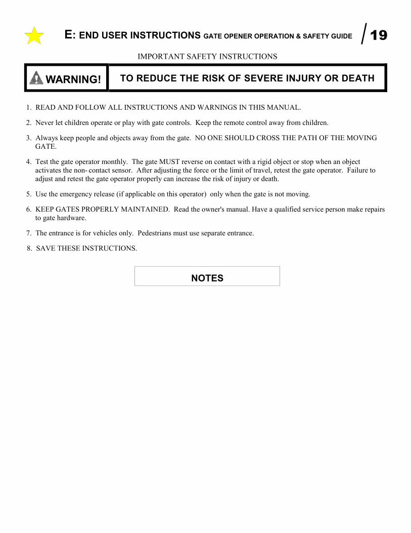
1 PHASE WIRING DIAGRAM
111305
3 PHASE WIRING DIAGRAM
111246
NOTES: - AS SHOWN TRANSFORMERS ARE WIRED FOR 230 VAC OPERATION. IF PRIMARY VOLTAGE IS 208 VAC THEN RED AND BLACK CONNECTIONS WOULD BE USED.
NOTES: - AS SHOWN TRANSFORMERS ARE WIRED FOR 230 VAC OPERATION. IF PRIMARY VOLTAGE IS 208 VAC THEN RED AND BLACK CONNECTIONS WOULD BE USED. - 440 VAC WIRING DIFFERS WITH RESPECT TO THE TRANSFORMER AND HEATER CONNECTIONS. REFERENCE THE DIAGRAM SUPPLIED WITH THE OPERATOR.
D: STARTING THE OPERATOR 18
E: END USER INSTRUCTIONS GATE OPENER OPERATION & SAFETY GUIDE 19
NOTES
TO REDUCE THE RISK OF SEVERE INJURY OR DEATH WARNING!
1. READ AND FOLLOW ALL INSTRUCTIONS AND WARNINGS IN THIS MANUAL.
2. Never let children operate or play with gate controls. Keep the remote control away from children.
3. Always keep people and objects away from the gate. NO ONE SHOULD CROSS THE PATH OF THE MOVING
GATE.
4. Test the gate operator monthly. The gate MUST reverse on contact with a rigid object or stop when an object
activates the non- contact sensor. After adjusting the force or the limit of travel, retest the gate operator. Failure to
adjust and retest the gate operator properly can increase the risk of injury or death.
5. Use the emergency release (if applicable on this operator) only when the gate is not moving.
6. KEEP GATES PROPERLY MAINTAINED. Read the owner's manual. Have a qualified service person make repairs
to gate hardware.
7. The entrance is for vehicles only. Pedestrians must use separate entrance.
8. SAVE THESE INSTRUCTIONS.
IMPORTANT SAFETY INSTRUCTIONS
E: END USER INSTRUCTIONS GATE OPENER OPERATION & SAFETY GUIDE 20
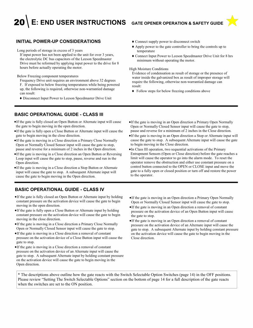
•If the gate is moving in an Open direction a Primary Open Normally
Open or Normally Closed Sensor input will cause the gate to stop,
pause and reverse for a minimum of 2 inches in the Close direction.
•If the gate is moving in an Open direction a Stop or Alternate input will
cause the gate to stop. A subsequent Alternate input will cause the gate
to begin moving in the Close direction.
•In Class III operation, two sequential activations of the Primary
Entrapment Sensors (Open or Close direction) before the gate reaches a
limit will cause the operator to go into the alarm mode. To reset the
operator remove the obstruction and either use constant pressure on a
control button connected to the OPEN or CLOSE input and move the
gate to a fully open or closed position or turn off and restore the power
to the operator.
BASIC OPERATIONAL GUIDE - CLASS IV
•If the gate is fully closed an Open Button or Alternate input by holding
constant pressure on the activation device will cause the gate to begin
moving in the open direction.
•If the gate is fully open a Close Button or Alternate input by holding
constant pressure on the activation device will cause the gate to begin
moving in the close direction.
•If the gate is moving in a Close direction a Primary Close Normally
Open or Normally Closed Sensor input will cause the gate to stop.
•If the gate is moving in a Close direction a removal of constant
pressure on the activation device of a Close Button input will cause the
gate to stop.
•If the gate is moving in a Close direction a removal of constant
pressure on the activation device of an Alternate input will cause the
gate to stop. A subsequent Alternate input by holding constant pressure
on the activation device will cause the gate to begin moving in the
Open direction.
•If the gate is moving in an Open direction a Primary Open Normally
Open or Normally Closed Sensor input will cause the gate to stop.
•If the gate is moving in an Open direction a removal of constant
pressure on the activation device of an Open Button input will cause
the gate to stop.
•If the gate is moving in an Open direction a removal of constant
pressure on the activation device of an Alternate input will cause the
gate to stop. A subsequent Alternate input by holding constant pressure
on the activation device will cause the gate to begin moving in the
Close direction.
BASIC OPERATIONAL GUIDE - CLASS III
•If the gate is fully closed an Open Button or Alternate input will cause
the gate to begin moving in the open direction.
•If the gate is fully open a Close Button or Alternate input will cause the
gate to begin moving in the close direction.
•If the gate is moving in a Close direction a Primary Close Normally
Open or Normally Closed Sensor input will cause the gate to stop,
pause and reverse for a minimum of 2 inches in the Open direction.
•If the gate is moving in a Close direction an Open Button or Reversing
Loop input will cause the gate to stop, pause, reverse and run in the
Open direction.
•If the gate is moving in a Close direction a Stop Button or Alternate
input will cause the gate to stop. A subsequent Alternate input will
cause the gate to begin moving in the Open direction.
* The descriptions above outline how the gate reacts with the Switch Selectable Option Switches (page 14) in the OFF positions.
Please review “Setting The Switch Selectable Options” section on the bottom of page 14 for a full description of the gate reacts
when the switches are set to the ON position.
INITIAL POWER-UP CONSIDERATIONS
Long periods of storage in excess of 3 years
If input power has not been applied to the unit for over 3 years,
the electrolytic DC bus capacitors of the Leeson Speedmaster
Drive must be reformed by applying input power to the drive for 8
hours before actually operating the motor.
Below Freezing component temperatures
Frequency Drive unit requires an environment above 32 degrees
F. If exposed to below freezing temperatures while being powered
up, the following is required, otherwise non-warrantied damage
can result:
♦Disconnect Input Power to Leeson Speedmaster Drive Unit
♦Connect supply power to disconnect switch
♦Apply power to the gate controller to bring the controls up to
temperature
♦Connect Input Power to Leeson Speedmaster Drive Unit for 8 hrs
minimum without operating the motor.
High Moisture Conditions
Evidence of condensation as result of storage or the presence of
water inside the galvanized box as result of improper storage will
require the following, otherwise non-warrantied damage can
result:
♦ Follow steps for below freezing conditions above
E: END USER INSTRUCTIONS GATE OPENER OPERATION & SAFETY GUIDE 21
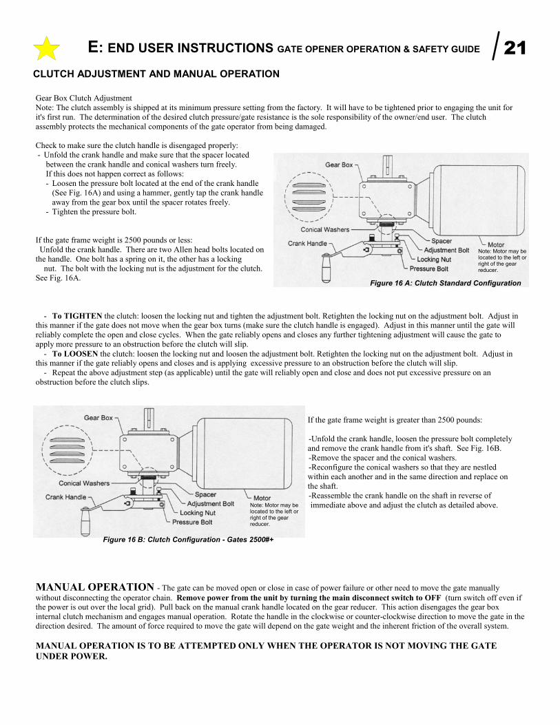
MANUAL OPERATION - The gate can be moved open or close in case of power failure or other need to move the gate manually
without disconnecting the operator chain. Remove power from the unit by turning the main disconnect switch to OFF (turn switch off even if the power is out over the local grid). Pull back on the manual crank handle located on the gear reducer. This action disengages the gear box
internal clutch mechanism and engages manual operation. Rotate the handle in the clockwise or counter-clockwise direction to move the gate in the
direction desired. The amount of force required to move the gate will depend on the gate weight and the inherent friction of the overall system.
MANUAL OPERATION IS TO BE ATTEMPTED ONLY WHEN THE OPERATOR IS NOT MOVING THE GATE
UNDER POWER.
CLUTCH ADJUSTMENT AND MANUAL OPERATION
Gear Box Clutch Adjustment
Note: The clutch assembly is shipped at its minimum pressure setting from the factory. It will have to be tightened prior to engaging the unit for
it's first run. The determination of the desired clutch pressure/gate resistance is the sole responsibility of the owner/end user. The clutch
assembly protects the mechanical components of the gate operator from being damaged.
Check to make sure the clutch handle is disengaged properly:
- Unfold the crank handle and make sure that the spacer located
between the crank handle and conical washers turn freely.
If this does not happen correct as follows:
- Loosen the pressure bolt located at the end of the crank handle
(See Fig. 16A) and using a hammer, gently tap the crank handle
away from the gear box until the spacer rotates freely.
- Tighten the pressure bolt.
If the gate frame weight is 2500 pounds or less:
Unfold the crank handle. There are two Allen head bolts located on
the handle. One bolt has a spring on it, the other has a locking
nut. The bolt with the locking nut is the adjustment for the clutch.
See Fig. 16A.
- To TIGHTEN the clutch: loosen the locking nut and tighten the adjustment bolt. Retighten the locking nut on the adjustment bolt. Adjust in this manner if the gate does not move when the gear box turns (make sure the clutch handle is engaged). Adjust in this manner until the gate will
reliably complete the open and close cycles. When the gate reliably opens and closes any further tightening adjustment will cause the gate to
apply more pressure to an obstruction before the clutch will slip.
- To LOOSEN the clutch: loosen the locking nut and loosen the adjustment bolt. Retighten the locking nut on the adjustment bolt. Adjust in this manner if the gate reliably opens and closes and is applying excessive pressure to an obstruction before the clutch will slip.
- Repeat the above adjustment step (as applicable) until the gate will reliably open and close and does not put excessive pressure on an
obstruction before the clutch slips.
If the gate frame weight is greater than 2500 pounds:
-Unfold the crank handle, loosen the pressure bolt completely
and remove the crank handle from it's shaft. See Fig. 16B.
-Remove the spacer and the conical washers.
-Reconfigure the conical washers so that they are nestled
within each another and in the same direction and replace on
the shaft.
-Reassemble the crank handle on the shaft in reverse of
immediate above and adjust the clutch as detailed above.
Figure 16 A: Clutch Standard Configuration
Figure 16 B: Clutch Configuration - Gates 2500#+
Note: Motor may be located to the left or right of the gear reducer.
Note: Motor may be located to the left or right of the gear reducer.
E: END USER INSTRUCTIONS GATE OPENER OPERATION & SAFETY GUIDE 22
To the Owner/End User of TYMETAL’s Gate Operator: Thank you for choosing a TYMETAL product. We are confident
you will have many years of use and satisfaction with your gate
operator. As you review these safety guidelines refer to Figures 17
(below) and 18 (page 22).
Our Gate Operator is part of your unique gate operating system,
which may consist of a variety of components, including the gate, the
gate tracks, posts, and electronic features. These components
combined present certain risks and safety issues of which you, the
end user, must be aware.
Each unique system presents a unique set of hazards which we
cannot possibly address individually. These instructions will help
you to identify the potential risks and safety issues your gate operator
system presents, and guide you as you make your system as safe as
possible for everyone who uses it.
Your first step is to consider the intended use of the gate system,
who will be using the gate system, and in what manner the system is
installed. You should have a clear understanding of how often the
gate will be opened, who will be opening it, whether children and the
general public will be near the gate system, and how close the gate
system is to public property. Once you have answered these
questions, you are ready to decide what safety measures must be
taken to prevent injury.
To minimize the risk of entrapment in your gate system, install the
following safety features:
• Electric gate edges
• Enclosed tracks
• Vertical guard posts
• Protective screen mesh
• Photoelectric sensors
• Instructional and precautionary signs
• Covers for exposed rollers
Each safety feature is a separate component in your gate system.
Read and follow all instructions for each of the components of your
unique system. Ensure that all instructions for mechanical
components, safety features and the TYMETAL Gate Operator
are available for everyone who will be using your gate system.
The two warning signs shipped with your Gate Operator (See
Figurez4, Page 5 of this manual) must be installed in prominent
positions on both sides of your gate. Keep them clean and legible.
Read and follow the safety points on this and the following page
which present the basic guidelines for the safest operation of your
gate operator system.
SAVE THESE INSTRUCTIONS !
ALL APPROPRIATE SAFETY FEATURES MUST BE INCORPORATED INTO YOUR GATE SYSTEM.
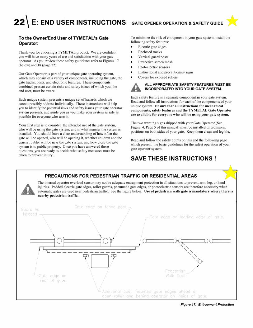
PRECAUTIONS FOR PEDESTRIAN TRAFFIC OR RESIDENTIAL AREAS
The internal operator overload sensor may not be adequate entrapment protection in all situations to prevent arm, leg, or hand
injuries. Padded electric gate edges, roller guards, pneumatic gate edges, or photoelectric sensors are therefore necessary when
automatic gates are used near pedestrian traffic. See the figure below. Use of pedestrian walk gate is mandatory where there is
nearby pedestrian traffic.
Figure 17: Entrapment Protection
E: END USER INSTRUCTIONS GATE OPENER OPERATION & SAFETY GUIDE 23
NO CHILDREN OR PETS ALLOWED: Never allow a child to operate gate controls, “ride” a gate, or play in the area of a gate.
Install and store all controls out of children’s reach. Also, pets must be kept away from the gate. Install a pedestrian gate in applications where
children or pets need access.
This entrance is for vehicles only. Pedestrians must use a separate entrance.
KEEP GATE IN SIGHT: Never activate the gate unless it is in sight. Install mounted controls in full view of the gate. Be sure the
gate area is clear before activating the gate, and watch the gate and gate area
as the gate is in motion.
LOCATE MANUAL CONTROLS SAFELY: A manual control such as a pushbutton or keyswitch must be included in
your gate system design to be used if automatic controls such as radio
controls or loop detectors do not function. Carefully consider the placement
of the manual control: It must be out of reach of the gate so that no one pushing the button or inserting the card is in the path of the gate or moving
parts; it must also be within sight of the gate so that the operator can watch
the gate and gate area during operation. The recommended minimum
distance between the gate or fence and manual control accessory is 10
feet.
MAINTAIN THE GATE AND GATE HARDWARE: A damaged gate or one that cannot be easily opened and closed
manually must be repaired before installing a gate operator. A poorly
operating gate may cause the load sensing device of the operator to fail,
causing a risk of entrapment. Never overtighten the clutch or load sensing
device to compensate for a poorly operating slide gate. Correct all mechanical problems on the gate and gate hardware before installing the
gate operator. Have a qualified service technician make repairs to the gate
and gate hardware.
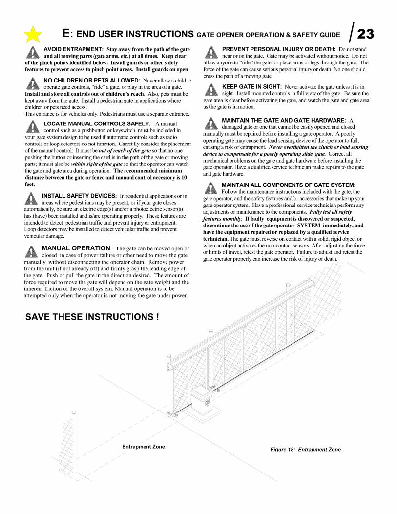
AVOID ENTRAPMENT: Stay away from the path of the gate
and all moving parts (gate arms, etc.) at all times. Keep clear
of the pinch points identified below. Install guards or other safety
features to prevent access to pinch point areas. Install guards on open
PREVENT PERSONAL INJURY OR DEATH: Do not stand near or on the gate. Gate may be activated without notice. Do not
allow anyone to “ride” the gate, or place arms or legs through the gate. The
force of the gate can cause serious personal injury or death. No one should
cross the path of a moving gate.
Figure 18: Entrapment Zone
MAINTAIN ALL COMPONENTS OF GATE SYSTEM: Follow the maintenance instructions included with the gate, the
gate operator, and the safety features and/or accessories that make up your
gate operator system. Have a professional service technician perform any
adjustments or maintenance to the components. Fully test all safety
features monthly. If faulty equipment is discovered or suspected,
discontinue the use of the gate operator SYSTEM immediately, and
have the equipment repaired or replaced by a qualified service
technician. The gate must reverse on contact with a solid, rigid object or when an object activates the non-contact sensors. After adjusting the force
or limits of travel, retest the gate operator. Failure to adjust and retest the
gate operator properly can increase the risk of injury or death.
Entrapment Zone
MANUAL OPERATION - The gate can be moved open or
closed in case of power failure or other need to move the gate
manually without disconnecting the operator chain. Remove power
from the unit (if not already off) and firmly grasp the leading edge of
the gate. Push or pull the gate in the direction desired. The amount of
force required to move the gate will depend on the gate weight and the
inherent friction of the overall system. Manual operation is to be
attempted only when the operator is not moving the gate under power.
INSTALL SAFETY DEVICES: In residential applications or in areas where pedestrians may be present, or if your gate closes
automatically, be sure an electric edge(s) and/or a photoelectric sensor(s)
has (have) been installed and is/are operating properly. These features are
intended to detect pedestrian traffic and prevent injury or entrapment.
Loop detectors may be installed to detect vehicular traffic and prevent
vehicular damage.
SAVE THESE INSTRUCTIONS !

It is recommended that the following maintenance be
performed on the operator at a minimum (for high use
installations (>100 cycles per day), steps noted below as
monthly should be performed every 2 weeks):
Monthly - Check the function of all safety devices
(photo-eyes, safety edges, etc.).
1. Photo eye inspection;
Break the beam of the photo eye in the direc-
tion of gate travel. The gate should either
stop then reverse for 2 seconds then stop or
if programmed for second option reverse to
full open or closed position.
Clean the lenses on both photo eyes.
Check mounting on both photo eyes- they
should not move or vibrate.
Check the alignment of photo eyes by shak-
ing both photo eyes lightly. The photo beam
should not break.
2. If the operator has reversing edges, they should
be hooked to the reversing circuit (not the entrap-
ment circuit).
To test the edges compress the edge at the
furthest point from the cable lead in.
The gate should stop then reverse to the full
reverse position. This should be tested on
both directions of gate travel if so equipped.
Check the mount of the reversing edge to
verify the edge is not slipping down.
Batteries should be replaced twice a year (be
sure to write the date of replacement on the
battery or cover).
On the receiver for the edge, inspect the
antenna mount (it must be isolated from
grounding).
3. Check other traffic control devices for proper
operation (loop detectors, traffic lighting, warning
devices, etc.).
Monthly – Check the drive chain tension (maintain 1”
to 2” sag maximum between chain support brackets).
Tighten as necessary.
Monthly – Check the operation of the gate; it should
operate smoothly and quietly back and forth. It should
not bang into the receiver catcher and should not pinch
the reversing edges. If so make the necessary adjust-
ment (see Gate Installation Manual).
Monthly - Check the clutch for slippage and gearbox
for oil level;
1. Check the clutch for proper adjustment - as the
gate travels close, place medium force against the
gate travel, if the gate pushes you away loosen the
clutch, if the gate stops with little force tighten the
clutch. See operator manual for adjustment of
proper force.
2. Check the gearbox for oil leaks (visual check
only).
Monthly - Inspect the electro-mechanical lock for oper-
ation and alignment. Adjust as necessary.
Monthly - Follow gate installation and maintenance
manual for gate related tuning and adjustments (at a
minimum check gate truck wheels and guide rollers for
proper adjustment and wear, replacing if necessary).
Quarterly - Check for proper manual operator operation.
Quarterly – Check sprockets, limit switches and chain
alignment;
1. Clean and lubricate the drive chain with a high
grade chain & cable lube spray (do not lubricate
the trucks or track area). Inspect drive sprocket
and idler sprockets.
2. Sprockets should be in a straight line and
should not be allowing the chain to rub on the
motor cabinet. Check the set screws on flange
bearings and sprockets for tightness.
3. Inspect limit drive chain. It should not be real
tight or real loose. There should be about ¼ inch
travel in chain.
Yearly - Check all wiring for integrity of insulation.
Yearly - Check the tightness of all electrical connec-
tions.
Yearly - Remove any foreign matter from the interior of
unit.
•
•
•
•
•
•
•
•

This Gate Operator is built in the USA and complies with all requirements of Underwriters' Laboratories Standard UL-325. P/N 111317 REV. O November 2008
Manufacturer’s Limited Warranty
TYMETAL warrants its gate operators to be free from defect in material and workmanship for a period of five (5) years from the date of
purchase for single family home use and three (3) years from the date of purchase for multi-family and commercial use. This warranty covers all components except the electronic circuit boards which are warranted for three (3) years from the date of purchase for single family home use and two (2) years from the date of purchase for multi-family and commercial use. To obtain service contact your dealer.
To obtain service under this warranty the buyer must obtain authorization instructions for the return of any goods from TYMETAL before
returning the goods. The goods must be returned with complete identification, with copy of proof-of-purchase, freight prepaid and in accordance with TYMETAL’s instructions or they will not be accepted. In no event will TYMETAL be responsible for goods returned
without proper authorization or identification.
Goods returned to TYMETAL for warranty repair within the warranty period, which upon receipt by TYMETAL are confirmed to be defective and covered by this limited warranty, will be repaired or replaced at TYMETAL’s sole option, at no cost and returned pre-paid. Defective parts will be repaired or replaced with new or factory rebuilt parts at TYMETAL’s sole option.
This limited warranty does not cover non-defect damage, damage caused by unreasonable use, damage caused by improper installation or
care, vandalism or lightning, fire or excessive heat, flood or other acts of God (including, but not limited to misuse, abuse or alterations, failure to provide reasonable and necessary maintenance), labor charges for dismantling or reinstalling a repaired or replaced unit, or replacement batteries.
These warranties are in lieu of all other warranties, either expressed or implied. All implied warranties of merchantability and/or fitness for a particular purpose are hereby disclaimed and excluded. Under no circumstances shall TYMETAL be liable for consequential, incidental or special damages arising in connection with the use or inability to use this product. In no event shall TYMETAL’s liability for breach of
warranty, breach of contract, negligence or strict liability exceed the cost of the product covered hereby. No person is authorized to assume for TYMETAL any other liability in connection with the sale of this product.
This warranty gives you specific legal rights. You may also have other rights which vary from state to state. Warranty effective after August 31, 2002.