Embed Size (px)
Citation preview
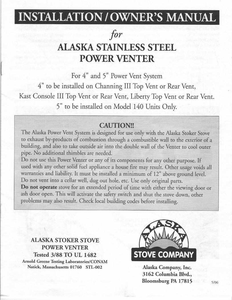
INSTALLATION/ OWNER'S MANUAL
[
forALASKA STAINLESS STEEL
POWER VENTER
For 4" and 5" Power Vent System
4" to be installed on Channing III Top Vent or Rear Vent,
Kast Console III Top Vent or Rear Vent, Liberty Top Vent or Rear Vent.
5" to be installed on Model 140 Units Only.
I
ilIII
I
I
r
CAUTION!!The Alaska Power Vent System is designed for use only with the Alaska Stoker Stoveto exhaust by-products of combustion through a combustible wall to the exterior of abuilding, and also to take outside air into the double wall of the Venter to cool outerpipe. No additional thimbles are needed.
Do not use this Power Venter or any of its components for any other purpose. Ifused with any other solid fuel appliance a house fire may result. Other usage voids allwarranties and liability. It must be installed a minimum of 12" above ground level.Do not vent into a cellar well, dug out hole, etc. Use only original parts.Do not operate stove for an extended period of time with either the viewing door orash door open. This will activate the safety switch and shut the stove down, other
problems may also result. Check local building codes before installing.
ALASKASTOKER STOVEPOWER VENTER
Tested 3/88 TO UL 1482Arnold Greene Testing Laboratories/CONAM
Natick, Massachusetts 01760 STL-002 Alaska Company, Inc.3162 Columbia Blvd.,
Bloomsburg PA 17815 5/06
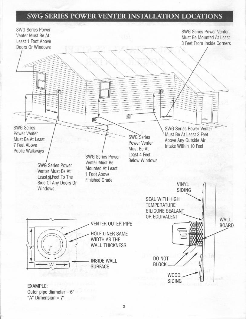
SWG SERIES POWER VENTER INSTALLATION LOCATIONS
SWGSeriesPowerVenterMust BeAtLeast1 FootAboveDoorsOrWindows
SWGSeriesPowerVenterMustBeAt Least7 FeetAbovePublicWalkways
SWGSeriesPowerVenterMust BeMountedAt Least3 FeetFromInsideCorners
SWGSeriesPowerVenterMustBeAtLeast4FeetToTheSideOfAnyDoorsOrWindows
SWGSeriesPowerVenterMust BeMountedAt Least1 FootAboveFinishedGrade
SWGSeriesPowerVenterMustBeAtLeast4 FeetBelowWindows
SWGSeriesPowerVenterMustBeAt Least3 FeetAboveAnyOutsideAirIntakeWithin10Feet
VINYLSIDING
SEALWITHHIGH ~TEMPERATURESILICONESEALANT .
lOREQUIVALENT~VENTEROUTERPIPE
HOLELINERSAMEWIDTHASTHEWALLTHICKNESS
INSIDEWALLSURFACE
EXAMPLE:Outerpipediameter=6""A"Dimension= 7"
2
HOW THE POWER VENTER WORKS IN CONJUNCTIONWITH THE ALASKASTOKERSTOVE .
The PowerVenter is a mechanical chimney that creates anegative pressure (draw) as a chimney does. TheBarometric Damper in your pipe allowsa balance to becreated between the draw of the PowerVenter and the
draw through the Fume Switch.This balance allowsthemaximum amount of super heated air to remain in theStoker Body to be radiated into your home.
If the PowerVenter becomes dirty or if a strong headwind pushes into the PowerVenter, room air is notdrawn through the Fume Switch allowing the heated airin the stove to push out and trip the snap disc - cuttingpower to the stove.
There is a "reset" button on the Fume Switch Box that
must be pushed to reset. (Seefigure I-B page 7) Alwayscheck this reset button first if you should lose your fire. Ifbutton needs resetting, then check for dirty PowerVentWheel and check that the Stove Pipe is not dirty.
Youshould also have a carbonmonoxide alarm in your
home. Test the gas alarm periodically to insure properoperation.
NOTE: A barometric damper is required forinstallation on all power vent systems.
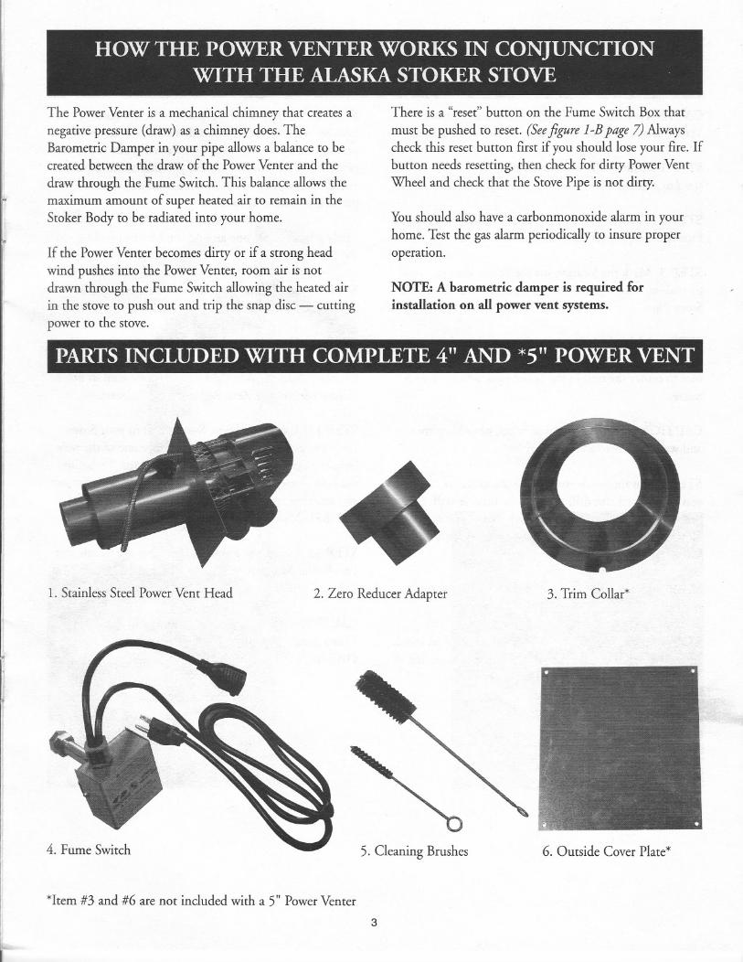
PARTS INCLUDED WITH COMPLETE 4" AND *5" POWER VENT
1. Stainless Steel Power Vent Head 2. Zero Reducer Adapter 3. Trim Collar*
4. Fume Switch
*Item #3 and #6 are not included with a 5" PowerVenter
5. Cleaning Brushes 6. Outside Cover Plate*
3
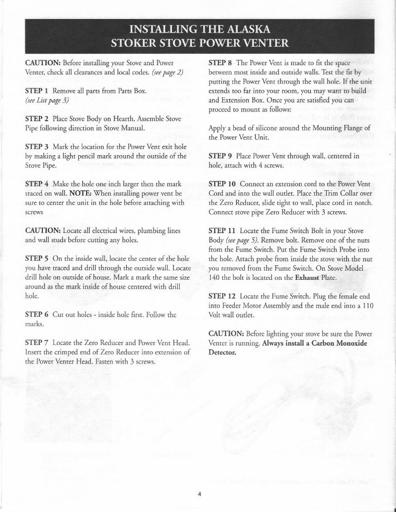
INSTALLING THE ALASKASTOKER STOVE POWER VENTER
CAUTION: Before installing your Stove and Power
Venter, check all clearancesand local codes. (seepage2)
STEP 1 Remove all parts from Parts Box.(see List page 3)
STEP 2 Place Stove Body on Hearth. Assemble Stove
Pipe following direction in Stove Manual.
STEP 3 Mark the location for the PowerVent exit hole
by making a light pencil mark around the outside of theStove Pipe.
STEP 4 Make the hole one inch larger then the marktraced on wall. NOTE: When installing power vent besure to center the unit in the hole before attaching withscrews
CAUTION: Locate all electricalwires, plumbing linesand wall studs before cutting any holes.
STEP 5 On the inside wall, locate the center of the hole
you have traced and drill through the outside wall. Locatedrill hole on outside of house. Mark a mark the same sizearound as the mark inside of house centered with drillhole.
STEP 6 Cut out holes - inside hole first. Follow themarks.
STEP 7 Locate the Zero Reducer and Power Vent Head.
Insert the crimped end of Zero Reducer into extension ofthe Power Venter Head. Fasten with 3 screws.
STEP 8 The PowerVent is made to fit the spacebetween most inside and outside walls.Test the fit byputting the PowerVent through the wall hole. If the unitextends too far into your room, you may want to buildand Extension Box. Once you are satisfiedyou canproceed to mount as follows:
Apply a bead of silicone around the Mounting Flange ofthe PowerVent Unit.
STEP 9 Place PowerVent through wall, centered inhole, attach with 4 screws.
STEP 10 Connect an extension cord to the PowerVentCord and into the wall outlet. Place the Trim Collar over
the Zero Reducer, slide tight to wall, place cord in notch.Connect stove pipe Zero Reducer with 3 screws.
STEP 11 Locate the Fume Switch Bolt in your StoveBody (seepage 5). Remove bolt. Remove one of the nutsfrom the Fume Switch. Put the Fume Switch Probe into
the hole. Attach probe from inside the stovewith the nutyou removed from the Fume Switch. On StoveModel140 the bolt is located on the Exhaust Plate.
STEP 12 Locate the Fume Switch. Plug the female endinto Feeder Motor Assembly and the male end into a 110Volt wall outlet.
CAUTION: Before lighting your stove be sure the PowerVenter is running. Always install a Carbon MonoxideDetector.
4
.
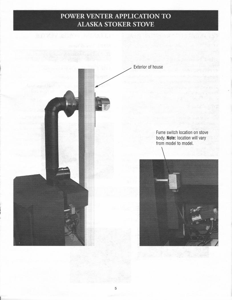
POWER VENTER APPLICATION TOALASKA STOKER STOVE
i/ Exteriorofhouse
Fumeswitchlocationonstovebody.Note:locationwill varyfrommodelto model.
5
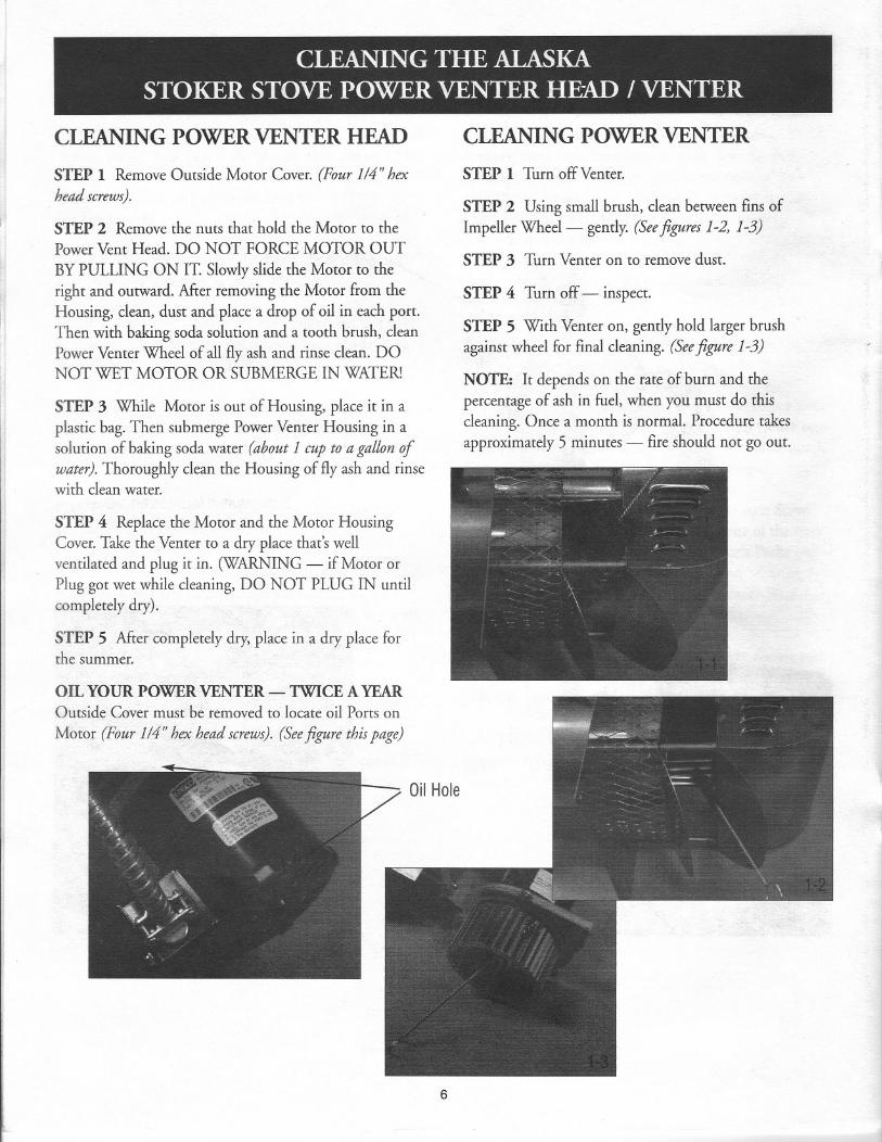
CLEANING THE ALASKASTOKER STOVE POWER VENTER HEAD / VENTER
CLEANING POWER VENTER HEAD
STEP 1 Remove Outside Motor Cover. (Four 114" hex
head screws).
STEP 2 Remove the nuts that hold the Motor to thePowerVent Head. DO NOT FORCE MOTOR OUT
BY PULLING ON IT. Slowlyslide the Motor to theright and outward. After removing the Motor from theHousing, clean, dust and place a drop of oil in each port.Then with baking soda solution and a tooth brush, cleanPowerVenter Wheel of all fly ash and rinse clean. DONOT WET MOTOR OR SUBMERGE IN WATER!
STEP 3 While Motor is out of Housing, place it in aplastic bag. Then submerge PowerVenter Housing in asolution of baking soda water (about 1 cup toa gallonofwater).Thoroughly clean the Housing of fly ash and rinsewith clean water.
STEP 4 Replace the Motor and the Motor HousingCover.Take the Venter to a dry place that's wellventilated and plug it in. (WARNING - if Motor orPlug got wet while cleaning, DO NOT PLUG IN untilcompletely dry).
STEP 5 After completely dry, place in a dry place forthe summer.
OIL YOUR POWERVENTER - TWICE A YEAROutside Cover must be removed to locate oil Ports on
Motor (Four 114" hex head screws). (See figure this page)
CLEANING POWER VENTER
STEP 1 Turn off Venter.
STEP 2 Using small brush, clean between fins ofImpeller Wheel- gently. (Seefigures 1-2, 1-3)
STEP 3 Turn Venter on to remove dust.
STEP4 Turn off- inspect.
STEP5 With Venteron, gentlyhold largerbrushagainstwheelfor finalcleaning.(Seefigure1-3)
NOTE: It depends on the rate of burn and thepercentage of ash in fuel, when you must do thiscleaning. Once a month is normal. Procedure takesapproximately 5 minutes - fire should not go out.
Oil Hole
6
ADJUSTING Barometric
Once you have a 2" to 3" fire on the grate, set yourBarometric at .02 - .04. This allowsheated air to remainin stoker to radiate out into home.
I
!I.
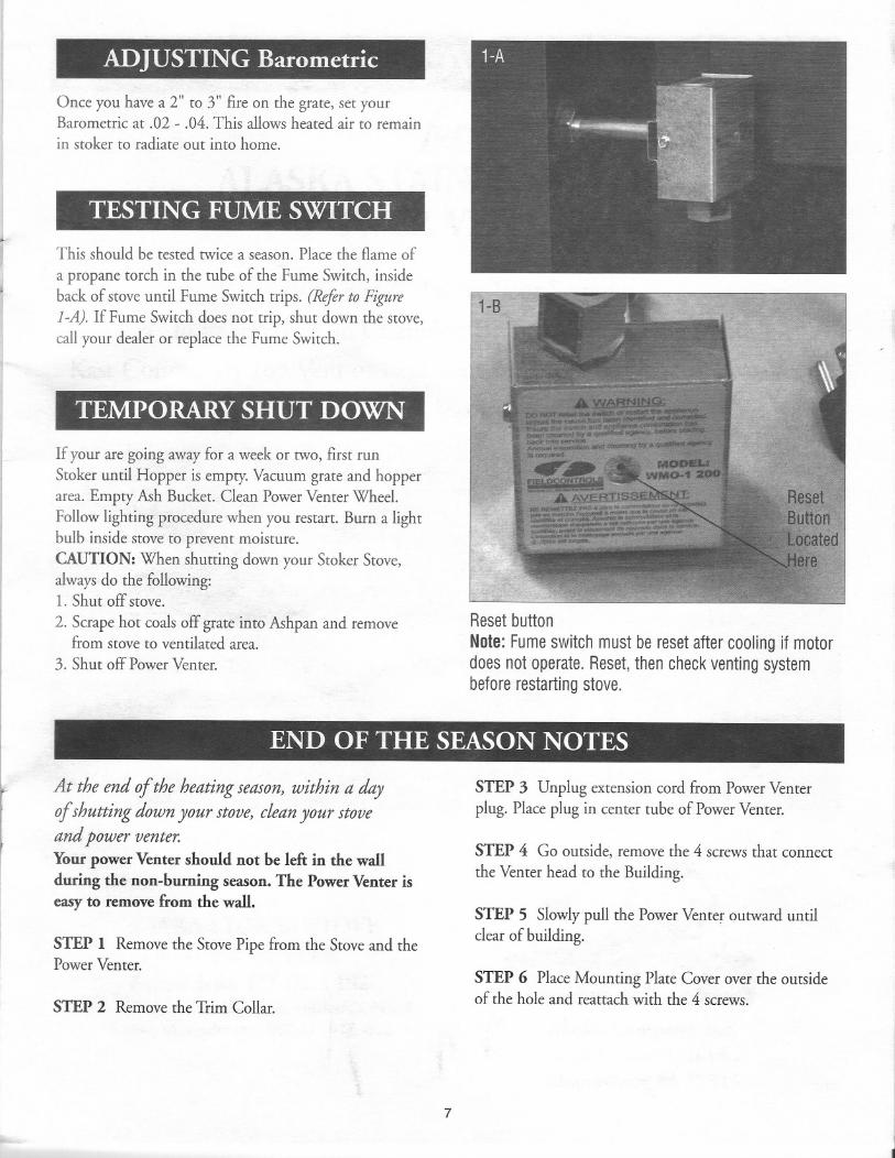
TESTING FUME SWITCH
This should be tested twice a season. Place the flame of
a propane torch in the tube of the Fume Switch, inside
back of stove until Fume Switch trips. (Refer to Figure
I-A). If Fume Switch does not trip, shut down the stove,call your dealer or replace the Fume Switch.
TEMPORARY SHUT DOWN
If your are going away for a week or two, first run
Stoker until Hopper is empty. Vacuum grate and hopperarea. Empty Ash Bucket. Clean PowerVenter Wheel.
Follow lighting procedure when you restart. Burn a lightbulb inside stove to prevent moisture.CAUTION: When shutting down your Stoker Stove,alwaysdo the following:1. Shut off stove.
2. Scrape hot coals off grate into Ashpan and removefrom stove to ventilated area.
3. Shut off PowerVenter.
1-8
ResetbuttonNote:Fumeswitchmustberesetaftercoolingif motordoesnotoperate.Reset,thencheckventingsystembeforerestartingstove.
END OF THE SEASON NOTES
,..
rI
~
At the end of the heating season, within a day
of shutting down your stove, clean your stove
and power venter.Your power Venter should not be left in the wallduring the non-burning season. The Power Venter iseasy to remove from the wall.
STEP 1 Remove the StovePipe from the Stoveand thePower Venter.
STEP 2 Remove the Trim Collar.
STEP 3 Unplug extension cord from PowerVenterplug. Place plug in center tube of PowerVenter.
STEP 4 Go outside, remove the 4 screws that connect
the Venter head to the Building.
STEP 5 Slowlypull the PowerVente):'outward untilclear of building.
STEP 6 Place Mounting Plate Cover over the outsideof the hole and reattach with the 4 screws.
7