Embed Size (px)
Citation preview
INSTALLATION/OWNER'S MANUAL10" Ported Enclosure with Built-in Amplifier
ALB10
2
Getting StartedThank you for purchasing the Dual ALB10 10" ported enclosure with built-in amplifier. Although Dual has attempted to ensure the information in this manual is accurate, please be aware that any part of it is subject to change without notice.
Please read entire manual before installation. Due to the technical nature of amplifiers, it is highly recommended that your Dual ALB10 is installed by a professional installer or an authorized dealer.
Before You Start
�•�Always�disconnect�the�negative�battery�terminal.�Consult�a�qualified�technician�for instructions if you are unsure.
�•�Avoid�installing�the�amplifier�where�it�would�be�subject�to�high�temperatures,�such as from direct sunlight, or where it would be subject to dust, dirt or excessive�vibration.�
�•�Use�extreme�caution�when�drilling�holes�to�avoid�damaging�fuel�lines�or�existing�vehicle�wiring.��
�•�All�amplifier�installations�require�power,�signal�and�speaker�wires�(not�included).
�•�An�amplifier�installation�kit�(sold�separately)�is�highly�recommended�to�facilitate�the�installation.�Consult�your�dealer�for�recommendations.��
Mounting Location
�•�Choose�a�mounting�location�for�the�ALB10.�Suggested�locations�include�behind�a seat or in the trunk.
�•�For�optimum�performance,�make�sure�to�provide�at�least�1"�of�space�around�all�sides of the amplifier.
•�Do�not�mount�the�ALB10�under�carpets�or�where�airflow�is�restricted.
�•�Do�not�install�the�ALB10�where�it�may�be�exposed�to�moisture.
�•�The�optimum�mounting�location�varies�between�vehicles.�Remember�to�test�all�amplifier functions before completing the final mounting procedure.
PREPARATION
3
The following installation instructions are intended to be used as a basic guideline. If you feel unsure about installing this speaker system yourself, Dual recommends�acquiring�the�services�of�a�professional�car�audio�installation�center.
Before�installation,�please�review�the�following�guidelines:
1. Be sure to carefully read and understand the instructions before attempting to install this product.
2.�If�additional�wiring�is�required,�we�recommend�running�all�wires�prior�to�mounting your enclosure in place.
3. To ensure reliable performance and minimize signal or power loss, use the highest�quality�connectors�available.
4.�Never�run�speaker�wires�underneath�your�vehicle.�Running�speaker�wires�inside�the�vehicle�provides�the�best�protection�from�exhaust,�heat�and�environmental�elements.�
5.�Avoid�running�wires�over,�near�or�through�sharp-edged�surfaces.�We�suggest�you also use rubber grommets to protect any wires routed through metal, especially the firewall.
6.�When�running�the�speaker�cable�to�the�amplifier,�avoid�running�it�near�sources�of�high�current�(i.e.�wiring�harnesses,�battery�cables).
Safety First
The following instructions are designed to ensure safety during installation and use of the ALB10. Failure to heed these instructions can result in injury or damage
to the unit or vehicle.
CAUTION!
INSTALLATION
4
Note: Be sure to follow specific instructions included with your amplifier installation kit (not included with this amplifier). The information below should be used a general guideline only.
Power Wire (+12V)•��Disconnect�negative�battery�terminal�before�proceeding.�Consult�a�qualified�
technician for instructions if you are unsure.•��Plan�wire�routing�before�cutting�any�wires�to�length.�Begin�by�routing�the�power�+12V�wire�from�the�battery�to�the�amplifier�location.�Use�a�grommet�when�running�wires�through�the�firewall�or�metal�openings.�Avoid�running�the�power�wire�near�existing�vehicle�wiring�to�prevent�induced�noise�from�entering�the�audio system.•��Use�extreme�caution�when�drilling�holes�to�avoid�damaging�fuel�lines�or�existing�vehicle�wiring.��•��The�+12V�wire�MUST�be�fused�within�18"�of�the�battery�for�protection�of�the�vehicle’s�electrical�system.
Ground Wire (GND)•��The�amplifier�ground�wire�should�be�as�short�as�possible.�Choose�a�clean�unpainted�section�of�metal�or�the�vehicle�chassis�when�attaching�the�ground�connection. Be sure to clean the area of any dirt or grease.
Remote Turn-on Wire (REM)•��The�remote�turn-on�wire�connects�to�the�head�unit's�amplifier�turn-on�lead�or�other�switched�12�volt�source.
Input Signal •��The�amplifier's�input�signal�connects�to�the�head�unit's�low�level�(RCA)�outputs.�
CAUTION •��Never�run�any�wires�underneath�or�outside�the�vehicle.
Connection Descriptions
INSTALLATION
5
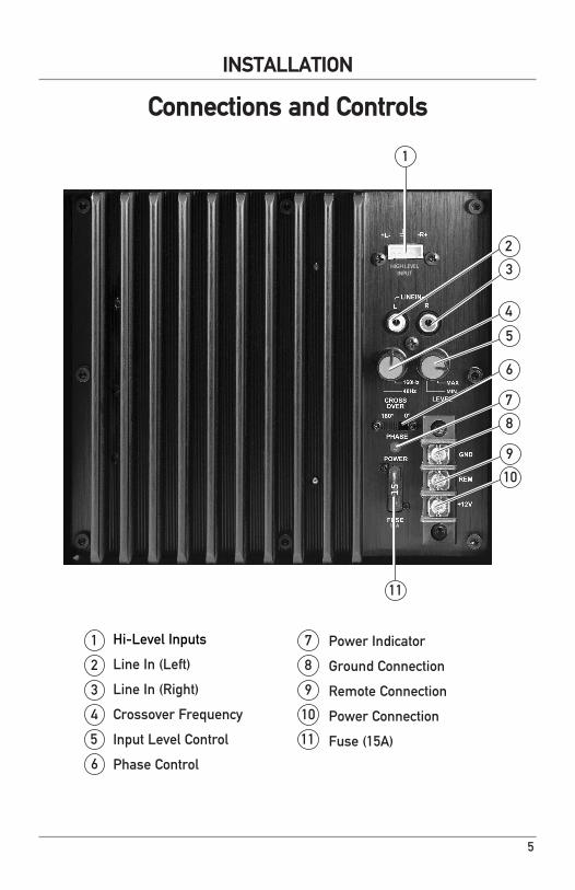
Hi-Level�Inputs
Line�In�(Left)
Line�In�(Right)
Crossover�Frequency�
Input�Level�Control
Phase�Control
1 7
2 8
3 9
4 10
Power Indicator
Ground�Connection
Remote�Connection
Power�Connection
Fuse�(15A)
Connections and Controls
INSTALLATION
5 11
1
2
3
4
5
6
7
8
9
10
6
HIGH LEVEL INPUT
15A
11
6
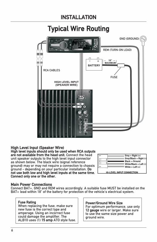
Main Power ConnectionsConnect�BAT+,�GND�and�REM�wires�accordingly.�A�suitable�fuse�MUST�be�installed�on�the�BAT+�lead�within�18"�of�the�battery�for�protection�of�the�vehicle’s�electrical�system.
BATTERY
HIGH LEVEL INPUT(SPEAKER WIRE)
18”MAXIMUM
Fuse RatingWhen�replacing�the�fuse,�make�sure�new fuse is the correct type and amperage.�Using�an�incorrect�fuse�could damage the amplifier. The ALB10�uses�(1)�15 amp ATO style fuse.
Power/Ground Wire SizeFor�optimum�performance,�use�only�12 gauge�wire�or�larger.�Make�sure�to use the same size power and ground wire.
Typical Wire Routing
INSTALLATION
High Level Input (Speaker Wire)High level inputs should only be used when RCA outputs are not available from the head unit.�Connect�the�head�unit�speaker�outputs�to�the�high�level�input�connector�as�shown�below.�The�black�wire�(signal�reference�ground)�may�or�may�not�require�a�connection�to�chassis�ground - depending on your particular installation. Do not use both low and high level inputs at the same time. Connect only one or the other.
HI-LEVEL INPUT CONNECTION
Grey = Right (+)Grey/Black = Right (-)Black = GroundWhite/Black = Left (-)White = Left (+)
HIGH LEVEL INPUT
15A
7
INSTALLATION
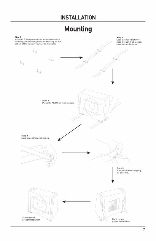
MountingStep 1Install ALB10 in place on the mounting base byscrewing the mounting brackets securely on thebottom of the trunk in your car as illustrated.
Step 2Lace straps so that theypass through the bracketsmounted on the base.
Step 3Place the ALB10 on the brackets.
Step 4Lace straps through buckles.
Step 5Fasten buckles as tightlyas possible.
Back view ofproper installation
Front view ofproper installation
8
INSTALLATION
Low�level�(RCA)�input�signal�is�preferred�for�best�performance. Typical trunk-mount installations require�a�17-20�foot�RCA�cable.�Most�trucks�and�behind-seat�applications�require�a�6-12�foot�RCA�cable.�Using�twisted�pair�construction�RCA�cables�will minimize noise.
The�adjustable�crossover�is�used�to�filter�out�frequencies�above�40Hz�~�160Hz.�Adjust�it�to�where�the ALB10 sound output blends with the rest of the sound system.
The phase control compensates for delay between the ALB10 output and the rest of the sound system. Begin with the phase control set to 0 degrees. If the�sound�is�adequate�from�the�normal�listening�position�inside�the�vehicle,�no�further�adjustment�is�necessary. If the sound is thin or lacking bass, adjust the phase control until the bass is full and punchy.
The�input�level�control�(LEVEL)�is�used�to�obtain�the�best possible match between the head unit audio output and the amplifier input. Begin by turning the�input�level�control�fully�counterclockwise.�Next,�turn�up�the�head�unit�volume�control�around�3/4�of�the�way�up.�Adjust�the�input�level�control�clockwise�until audible distortion is heard, then slightly counterclockwise�to�provide�the�best�match. The�LED�indicator�illuminates�green�during�normal�operation.
Input Signal ConnectionsLow Level (RCA)
Crossover Frequency Control
Phase Control
Input Level Control
LED Indicator
Control Setup and Adjustment
9
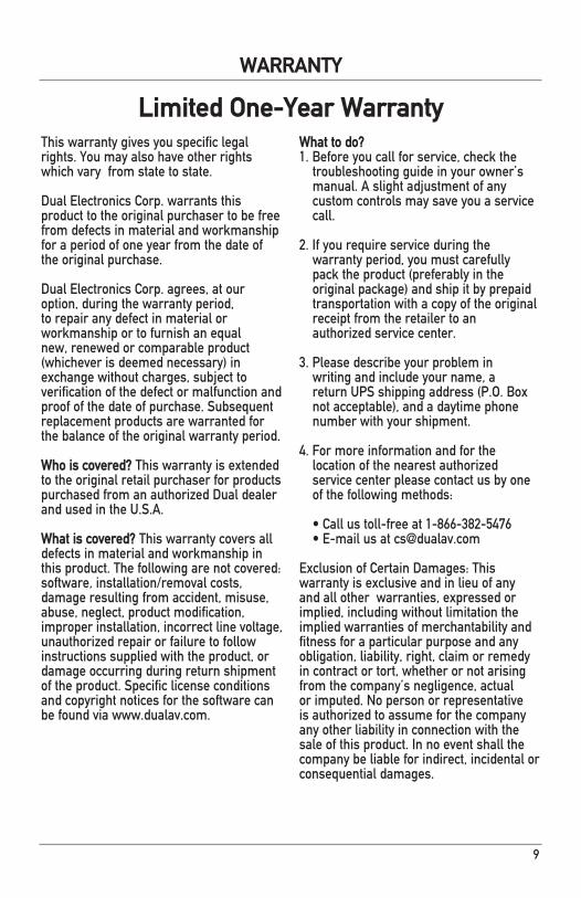
This�warranty�gives�you�specific�legal�rights.�You�may�also�have�other�rights�which�vary��from�state�to�state.�
Dual�Electronics�Corp.�warrants�this�product to the original purchaser to be free from defects in material and workmanship for a period of one year from the date of the original purchase.
Dual�Electronics�Corp.�agrees,�at�our�option, during the warranty period, to repair any defect in material or workmanship�or�to�furnish�an�equal�new, renewed or comparable product (whichever�is�deemed�necessary)�in�exchange without charges, subject to verification�of�the�defect�or�malfunction�and�proof�of�the�date�of�purchase.�Subsequent�replacement products are warranted for the balance of the original warranty period.
Who is covered? This warranty is extended to the original retail purchaser for products purchased from an authorized Dual dealer and�used�in�the�U.S.A.
What is covered?�This�warranty�covers�all�defects in material and workmanship in this�product.�The�following�are�not�covered:�software,�installation/removal�costs,�damage resulting from accident, misuse, abuse, neglect, product modification, improper�installation,�incorrect�line�voltage,�unauthorized repair or failure to follow instructions supplied with the product, or damage occurring during return shipment of�the�product.�Specific�license�conditions�and copyright notices for the software can be�found�via�www.dualav.com.
What to do? 1.�Before�you�call�for�service,�check�the�troubleshooting�guide�in�your�owner’s�manual. A slight adjustment of any custom�controls�may�save�you�a�service�call.
2.�If�you�require�service�during�the�warranty period, you must carefully pack�the�product�(preferably�in�the�original package) and ship it by prepaid transportation with a copy of the original receipt from the retailer to an authorized�service�center.�
3. Please describe your problem in writing and include your name, a return�UPS�shipping�address�(P.O.�Box�not acceptable), and a daytime phone number with your shipment.
4.�For�more�information�and�for�the�location of the nearest authorized service�center�please�contact�us�by�one�of�the�following�methods:
•�Call�us�toll-free�at�1-866-382-5476•�E-mail�us�at�[email protected]
Exclusion�of�Certain�Damages:�This�warranty�is�exclusive�and�in�lieu�of�any�and all other warranties, expressed or implied, including without limitation the implied warranties of merchantability and fitness for a particular purpose and any obligation, liability, right, claim or remedy in contract or tort, whether or not arising from�the�company’s�negligence,�actual�or�imputed.�No�person�or�representative�is authorized to assume for the company any other liability in connection with the sale�of�this�product.�In�no�event�shall�the�company be liable for indirect, incidental or consequential�damages.
Limited One-Year Warranty
WARRANTY
10
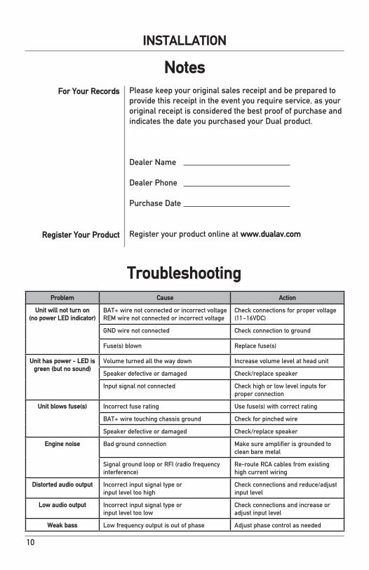
Please keep your original sales receipt and be prepared to provide�this�receipt�in�the�event�you�require�service,�as�your�original receipt is considered the best proof of purchase and indicates the date you purchased your Dual product.
Dealer Name
Dealer Phone
Purchase Date
Register�your�product�online�at�www.dualav.com
For Your Records
Register Your Product
Notes
INSTALLATION
Problem Cause Action
Unit will not turn on(no power LED indicator)
BAT+�wire�not�connected�or�incorrect�voltage�REM�wire�not�connected�or�incorrect�voltage
Check�connections�for�proper�voltage�(11~16VDC)
GND wire not connected Check�connection�to�ground
Fuse(s)�blown Replace�fuse(s)
Unit has power - LED is green (but no sound)
Volume turned all the way down Increase�volume�level�at�head�unit
Speaker�defective�or�damaged Check/replace�speaker
Input signal not connected Check�high�or�low�level�inputs�for�proper connection
Unit blows fuse(s) Incorrect fuse rating Use�fuse(s)�with�correct�rating
BAT+ wire touching chassis ground Check�for�pinched�wire
Speaker�defective�or�damaged Check/replace�speaker
Engine noise Bad ground connection Make�sure�amplifier�is�grounded�to�clean bare metal
Signal�ground�loop�or�RFI�(radio�frequency�interference)
Re-route�RCA�cables�from�existing�high current wiring
Distorted audio output Incorrect input signal type or input�level�too�high
Check�connections�and�reduce/adjust�input�level
Low audio output Incorrect input signal type orinput�level�too�low
Check�connections�and�increase�or�adjust�input�level
Weak bass Low�frequency�output�is�out�of�phase� Adjust phase control as needed
Troubleshooting
11
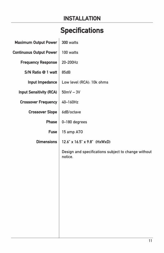
300 watts
100 watts
20-200Hz
85dB
Low�level�(RCA):�10k�ohms
50mV – 3V
40–160Hz
6dB/octave
0–180�degrees
15 amp ATO
12.6"�x�16.5"�x�9.8"��(HxWxD)
Design and specifications subject to change without notice.
Maximum Output Power
Continuous Output Power
Frequency Response
S/N Ratio @ 1 watt
Input Impedance
Input Sensitivity (RCA)
Crossover Frequency
Crossover Slope
Phase
Fuse
Dimensions
Specifications
INSTALLATION

Dual�Electronics�Corp.Toll�Free:�1-866-382-5476
Monday-Friday,�9AM-5PM�EST
www.dualav.com©2013�Dual�Electronics�Corp.�All�rights�reserved.
NSA1013-V01Printed�in�China