Embed Size (px)
Citation preview

2
1
0 4
3
bar
Reset Burner On
Flame Failure
Power On
Installation & Service Instructions Performa24 Eco HE
This is a Wall Mounted Powered Flue Condensing Combination Boiler Gas Fired Central Heating Unit.
The boiler meets the requirements of Statutory Instrument “ The Boiler (Efficiency) Regulations 1993 No 3083” and isdeemed to meet the requirements of Directive 92/42/EEC on the energy efficiency requirements for new hot waterboilers fired with liquid or gaseous fuels:-
Type test for purpose of Regulation 5 certified by: Notified Body 0051.
Product/Production certified by:Notified Body 0051.
For use in GB/IE only.

Publication No. 51118112
Natural Gas
Potterton Performa 24 Eco HEG.C.No 47 393 11
This product has an energy rating (B) on a scale of A to G.For more information see www.boilers.org.uk. This is a certification mark.
3
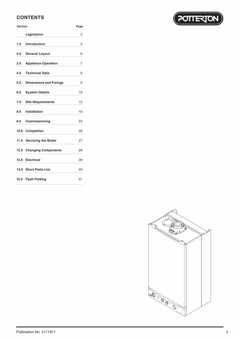
CONTENTS
Publication No. 5111811
Legislation 4
1.0 Introduction 5
2.0 General Layout 6
3.0 Appliance Operation 7
4.0 Technical Data 8
5.0 Dimensions and Fixings 9
6.0 System Details 10
7.0 Site Requirements 13
8.0 Installation 19
9.0 Commissioning 24
10.0 Completion 26
11.0 Servicing the Boiler 27
12.0 Changing Components 29
13.0 Electrical 39
14.0 Short Parts List 40
15.0 Fault Finding 41
Section Page
LEGISLATION
4 Publication No. 5111811
Codes of Practice, most recent version shouldbe used
IMPORTANT - Installation, Commissioning, Service & Repair
This appliance must be installed in accordance with the manufacturer’sinstructions and the regulations in force. Read the instructions fully beforeinstalling or using the appliance.
In GB, this must be carried out by a competent person as stated in the GasSafety (Installation & Use) Regulations.
Definition of competence: A person who works for a CORGI registeredcompany and holding current certificates in the relevant ACS modules, orvalid ACoP equivalents, is deemed competent.
In IE, this must be carried out by a competent person as stated in I.S. 813“Domestic Gas Installations”.
Lifting - This product should be lifted and handled by two people. Stoopingshould be avoided and protective equipment worn where necessary. Carrying& lifting equipment should be used as required, e.g. when installing in a loftspace.
The addition of anything that may interfere with the normal operation of theappliance without express written permission from the manufacturer or hisagent could invalidate the appliance warranty. In GB this could also infringethe Gas Safety (Installation and Use) Regulations.
Warning - Check the information on the data plate is compatible with localsupply conditions.
“Benchmark” Log Book
As part of the industry-wide “Benchmark” initiative all Potterton boilers nowinclude an Installation, Commissioning and Service Record Log Book. Pleaseread the Log Book carefully and complete all sections relevant to theappliance and installation. These include sections on the type of controlsemployed, flushing the system, burner operating pressure etc. The details ofthe Log Book will be required in the event of any warranty work. Also, there isa section to be completed at each subsequent regular service visit. The LogBook must be left with the user.
All CORGI registered installers carry a CORGI identification card and have aregistration number. Both should be recorded in your boiler Log Book. Youcan check your installer is registered by telephoning +44 (0)1256 372300 orwriting to:-
1 Elmwood,Chineham Business Park,
Crockford Lane,Basingstoke. RG24 8WG
Potterton declare that no substances harmful tohealth are contained in the appliance or usedduring appliance manufacture.
The appliance is suitable only for installation in GBand IE and should be installed in accordance withthe rules in force, and only used in a suitablyventilated location.
In GB, the installation must be carried out by a CORGIRegistered Installer. It must be carried out in accordancewith the relevant requirements of the:• Gas Safety (Installation & Use) Regulations.• The appropriate Building Regulations either The
Building Regulations, The Building Regulations (Scotland), Building Regulations (Northern Ireland).
• The Water Fittings Regulations or Water Byelaws in Scotland.
• The Current I.E.E. Wiring Regulations.
Where no specific instructions are given, referenceshould be made to the relevant British Standard Code ofPractice.
In IE, the installation must be carried out by a competentPerson and installed in accordance with the currentedition of I.S. 813 ‘Domestic Gas Installations’, thecurrent Building Regulations and reference should bemade to the current ETCI rules for electrical installation.
All systems must be thoroughly flushed andtreated with inhibitor (see section 6.2).
In GB the following Codes of Practice apply:Standard ScopeBS 6891 Gas Installation.BS 5546 Installation of hot water supplies for
domestic purposes.BS 5449 Forced circulation hot water systems.BS 6798 Installation of gas fired hot water boilers.BS 5440 Part 1 Flues.BS 5440 Part 2 Ventilation.BS 7074 Expansion vessels and ancillary equipment
for sealed water systems.BS 7593 Treatment of water in domestic hot water
central heating systems.
In IE the following Codes of Practice apply:Standard ScopeI.S. 813 Domestic Gas Installations.The following BS standards give valuable additional information;BS 5546 Installation of hot water supplies for
domestic purposes.BS 5449 Forced circulation hot water systems.BS 7074 Expansion vessels and ancillary equipment
for sealed water systems.BS 7593 Treatment of water in domestic hot water
central heating systems.
5
1.0 INTRODUCTION
Publication No. 5111811
1.1 Description
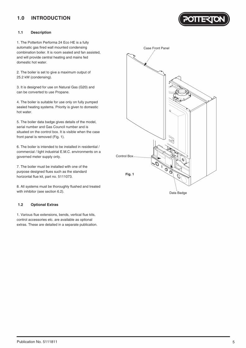
1. The Potterton Performa 24 Eco HE is a fullyautomatic gas fired wall mounted condensingcombination boiler. It is room sealed and fan assisted,and will provide central heating and mains feddomestic hot water.
2. The boiler is set to give a maximum output of 25.2 kW (condensing).
3. It is designed for use on Natural Gas (G20) andcan be converted to use Propane.
4. The boiler is suitable for use only on fully pumpedsealed heating systems. Priority is given to domestichot water.
5. The boiler data badge gives details of the model,serial number and Gas Council number and issituated on the control box. It is visible when the casefront panel is removed (Fig. 1).
6. The boiler is intended to be installed in residential /commercial / light industrial E.M.C. environments on agoverned meter supply only.
7. The boiler must be installed with one of thepurpose designed flues such as the standardhorizontal flue kit, part no. 5111073.
8. All systems must be thoroughly flushed and treatedwith inhibitor (see section 6.2).
1.2 Optional Extras
1. Various flue extensions, bends, vertical flue kits,control accessories etc. are available as optionalextras. These are detailed in a separate publication.
Data Badge
Fig. 1
Control Box
Case Front Panel
2.0 GENERAL LAYOUT
6 Publication No. 5111811
2.1 Layout
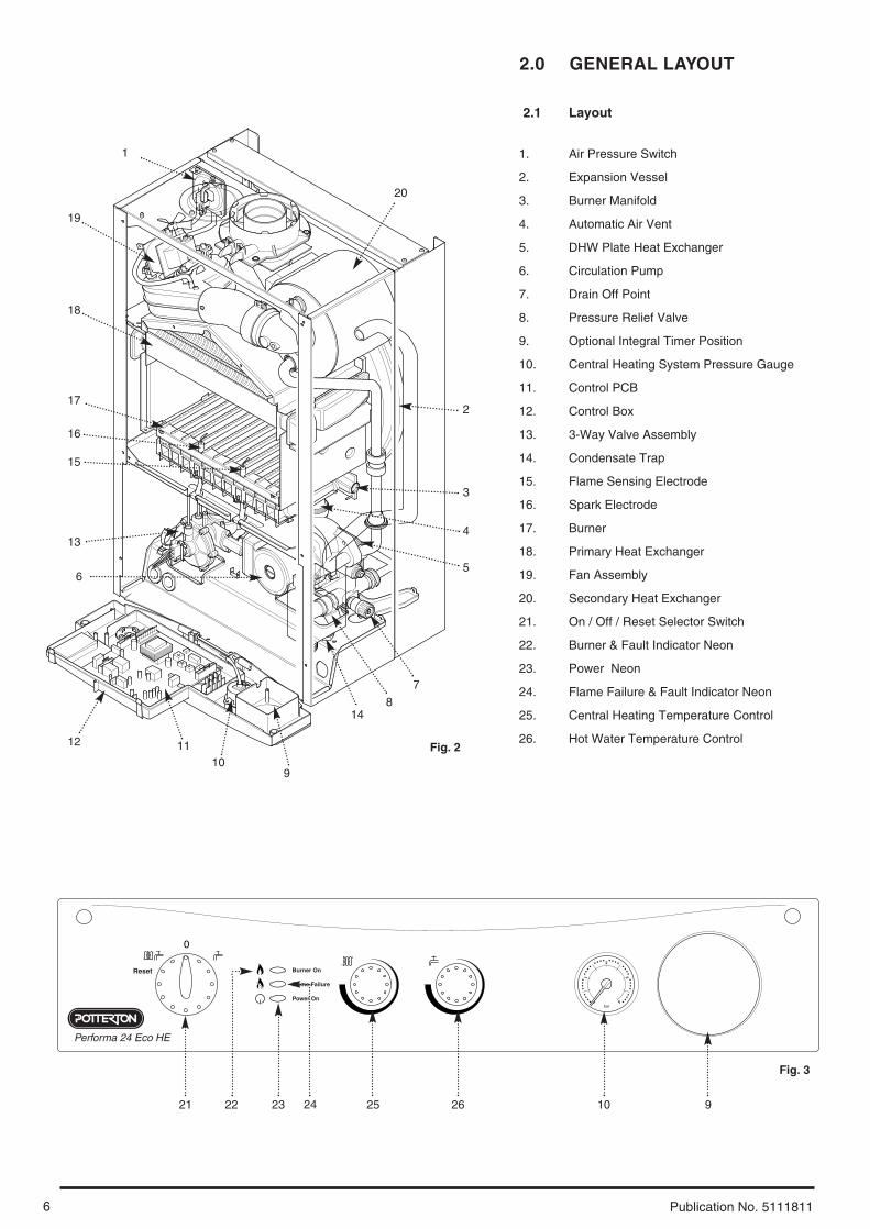
1. Air Pressure Switch
2. Expansion Vessel
3. Burner Manifold
4. Automatic Air Vent
5. DHW Plate Heat Exchanger
6. Circulation Pump
7. Drain Off Point
8. Pressure Relief Valve
9. Optional Integral Timer Position
10. Central Heating System Pressure Gauge
11. Control PCB
12. Control Box
13. 3-Way Valve Assembly
14. Condensate Trap
15. Flame Sensing Electrode
16. Spark Electrode
17. Burner
18. Primary Heat Exchanger
19. Fan Assembly
20. Secondary Heat Exchanger
21. On / Off / Reset Selector Switch
22. Burner & Fault Indicator Neon
23. Power Neon
24. Flame Failure & Fault Indicator Neon
25. Central Heating Temperature Control
26. Hot Water Temperature Control
19
18
17
14
15
16
13
12 1110
9
21 22 23 24 25 26 10 9
7
6
3
4
5
8
2
1
2
1
0 4
3
bar
Reset Burner On
Flame Failure
Power On
Performa 24 Eco HE
Fig. 2
Fig. 3
20
7
3.0 APPLIANCE OPERATION
Publication No. 5111811
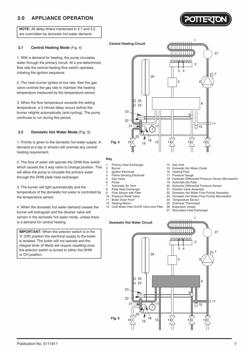
NOTE: All delay timers mentioned in 3.1 and 3.2are overridden by domestic hot water demand.
3.1 Central Heating Mode (Fig. 4)
1. With a demand for heating, the pump circulateswater through the primary circuit. At a pre-determinedflow rate the central heating flow switch operates,initiating the ignition sequence.
2. The main burner ignites at low rate, then the gasvalve controls the gas rate to maintain the heatingtemperature measured by the temperature sensor.
3. When the flow temperature exceeds the settingtemperature, a 3 minute delay occurs before theburner relights automatically (anti-cycling). The pumpcontinues to run during this period.
3.2 Domestic Hot Water Mode (Fig. 5)
1. Priority is given to the domestic hot water supply. Ademand at a tap or shower will override any centralheating requirement.
2. The flow of water will operate the DHW flow switchwhich causes the 3 way valve to change position. Thiswill allow the pump to circulate the primary waterthrough the DHW plate heat exchanger.
3. The burner will light automatically and thetemperature of the domestic hot water is controlled bythe temperature sensor.
4. When the domestic hot water demand ceases theburner will extinguish and the diverter valve willremain in the domestic hot water mode, unless thereis a demand for central heating.
IMPORTANT: When the selector switch is in the‘0’ (Off) position the electrical supply to the boileris isolated. The boiler will not operate and the integral timer (if fitted) will require resetting once the selector switch is turned to either the DHWor CH position.
1
2
4
5 6
7
8
9
10 11
1213141516
17
1819
20
21
22
23
2425
26
3
1 Primary Heat Exchanger2 Burner 3 Ignition Electrode4 Flame Sensing Electrode5 Gas Valve6 Pump7 Automatic Air Vent8 Plate Heat Exchanger9 Flow Sensor with Filter10 Pressure Relief Valve11 Boiler Drain Point12 Heating Return13 Cold Water Inlet On/Off Valve and Filter
14 Gas Inlet15 Domestic Hot Water Outlet16 Heating Flow17 Pressure Gauge18 Hydraulic Differential Pressure Sensor Microswitch19 Automatic By-Pass20 Hydraulic Differential Pressure Sensor21 Diverter Valve Assembly22 Domestic Hot Water Flow Priority Assembly23 Domestic Hot Water Flow Priority Microswitch24 Temperature Sensor25 Overheat Thermostat26 Expansion Vessel27 Secondary Heat Exchanger
Key
Central Heating Circuit
Domestic Hot Water Circuit
Fig. 4
Fig. 5
1
2
4
5 6
7
8
9
10 11
1213141516
17
1819
20
21
22
23
2425
26
3
27
27

4.0 TECHNICAL DATA
8 Publication No. 5111811
0200 400 600 800 1000 1200
0.5
1
1.5
2
2.5
3
3.5
4
Met
re (
wg)
Flow Rate (l/h)
Pump - Available Head
0
5
4.5
TemperaturesC.H. Flow Temp (adjustable)
35°C to 85°C max (± 5°C)
D.H.W. Flow Temp 35°C to 65°C max (± 5°C)dependent upon flow rate
This value is used in the UK Government’s Standard Assessment
Procedure (SAP) for energy rating of dwellings. The test data from
which it has been calculated have been certified by 0051.
SEDBUK Declaration For Performa 24 Eco HE
The seasonal efficiency (SEDBUK) is 87.3% (89.3% LPG)
Band B
Heat Input CH
Max Min
kW 24.8 10.6
Heat Output CH (Non-Condensing)Max Min
kW 24 9.8
Electrical Supply 230V~ 50Hz (Appliance must be connected to an earthed supply)
Power Consumption 170W
External Fuse Rating 3A
Internal Fuse Rating Fuse 2A Fast Blow to BS 4265
Appliance Category CAT II 2H 3P
Inlet Pressure (Natural Gas - G20)mbar 20
Burner Injector (Natural Gas - G20)15 x 1.18mm Diameter
Burner Pressure (Natural Gas - G20)Max Rate Min Rate
mbar 10.2 ± 0.5 2 ± 0.2
Appliance Type C12 C32
Heat Output CH (Condensing)Max Min
kW 25.2 10.1
Heat Input DHWMax
kW 24.8
Heat Output DHWMax
kW 24
Flue Terminal Diameter 100mmDimensions Projection 125mm
Outercase DimensionsCasing Height - 780mmOverall Height Inc FlueElbow - 965mmCasing Width - 450mmCasing Depth - 345mm
ClearancesAbove Casing 200 mm MinBelow Casing 200 mm MinFront 450 mm Min (For Servicing)
Front 5 mm Min (In Operation)
L.H. Side 5 mm MinR.H. Side 5 mm Min (In Operation)
20 mm Min (See Note*)
*NOTE: The boiler can be operated with aclearance of 5mm at the right. This is alsosufficient for routine maintenance.However a clearance of 20mm is requiredif it is necessary to remove the secondaryheat exchanger. This should beconsidered when siting the appliance andin the event of any subsequent alterationsin the area of installation
Weights kgPackaged Boiler Carton 50Installation Lift Weight 43.5
Connections copper tailsGas Supply - 22mmCentral Heating Flow - 22mmCentral Heating Return - 22mmCold Water Mains Inlet - 15mmDHW Flow - 15mmPressure Relief Discharge - 15mm
NOx Class 3
Electrical Protection IPX4D
Condensate Drain 1” BSP
LPG Propane - G31
Burner Injector 15 x 0.77mm diameter
Burner PressurePropane mbar
Inlet Pressuresmbar
Max Rate21.8 ± 0.5
Min Rate4.4 ± 0.2
37
Central Heating Primary CircuitPressures
barSafety Discharge 3Max Operating 2.5Min Operating 0.5Recommend Operating 1-2
DHW Circuit barPressuresMax Operating 8Min Operating 0.2
Min Operating Pressureat 11.1 l/min 0.9
Flow Rates l/min DHW Flow Rate @ 30°CRise 11.5
DHW Flow Rate@ 35°CRise 9.8
Min WorkingDHW Flow Rate 2.5
PumpAvailable Head See graph below
Expansion Vessel - (For Central Heatingonly. Integral with appliance)
barMin Pre-charge Pressure 0.5
litreMax Capacity of CH System 125
Primary Water Content 1.0of Boiler (unpressurised)
Max Gas Rate (Natural Gas - G20)(After 10 mins)
m3/h 2.62
9
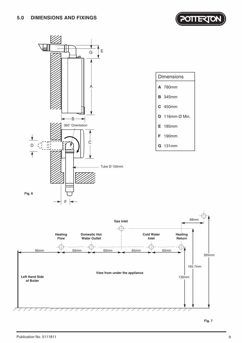
5.0 DIMENSIONS AND FIXINGS
Publication No. 5111811
Dimensions
A 780mm
B 345mm
C 450mm
D 116mm Ø Min.
E 185mm
F 190mm
G 131mm
65mm 65mm 65mm 65mm
View from under the appliance
Gas Inlet
Heating Flow
Domestic HotWater Outlet
Cold Water Inlet
Heating Return
130mm
165.7mm
95mm
Left Hand Sideof Boiler
Fig. 7
360° Orientation
Tube Ø 100mm
DC
B
A
EG
F
Fig. 6
68mm
265mm
6.0 SYSTEM DETAILS
10 Publication No. 5111811
6.1 Information
1. The Potterton Performa 24 Eco HE CondensingCombination Boiler is a ‘Water Byelaws Scheme -Approved Product’. To comply with the Water Byelawsyour attention is drawn to the following installationrequirements and notes (IRN).
a) IRN 001 - See text of entry for installation requirements and notes.
b) IRN 302 - Byelaw 14.2. Reference to the WRc publications, ‘Water fittings andmaterials directory’ and ‘Water supply byelaws guide’ givefull details of byelaws and the IRNs.
6.2 Central Heating Circuit
1. The appliance is suitable for fully pumped SEALEDSYSTEMS ONLY.
Treatment of Water Circulating Systems• All recirculatory water systems will be subject to corrosion unless an appropriate water treatment is applied. This means that the efficiency of the system willdeteriorate as corrosion sludge accumulates within thesystem, risking damage to pump and valves, boiler noiseand circulation problems.
• When upgrading existing systems that exhibit evidenceof sludging, it is advisable to clean the system prior totreatment in order to remove any sludge and reduce thelikelihood of these deposits damaging new components.
• When fitting new systems flux will be evident within thesystem, which can lead to damage of system components.
• All systems must be thoroughly drained and flushedout. The recommended flushing and cleansing agents areBetz-Dearborn Sentinel X300 or X400 and Fernox Superfloc Universal Cleanser which should be usedfollowing the flushing agent manufacturer’s instructions.
• System additives - corrosion inhibitors and flushing agents/descalers should be suitable for aluminium andcomply to BS7593 requirements. The only systemadditives recommended are Betz-Dearborn Sentinel X100and Fernox-Copal which should be used following theinhibitor manufacturer’s instructions.
Failure to flush and add inhibitor to the system willinvalidate the appliance warranty.
• It is important to check the inhibitor concentration after installation, system modification and at every service in accordance with the manufacturer’s instructions. (Test kits are available from inhibitor stockists.)
• For information or advice regarding any of the abovecontact the Potterton Helpline.
6.3 Bypass
1. The boiler is fitted with an automatic integral bypass.
6.4 System Control
1. The boiler is designed for use in a heating systemthat incorporates external controls, i.e. a minimum of atimer device.
2. An integral electro-mechanical or electronic timer isavailable as an optional extra.
3. For optimum operating conditions and maximumeconomy the fitting of a programmable thermostat isrecommended.
11
6.0 SYSTEM DETAILS
Publication No. 5111811
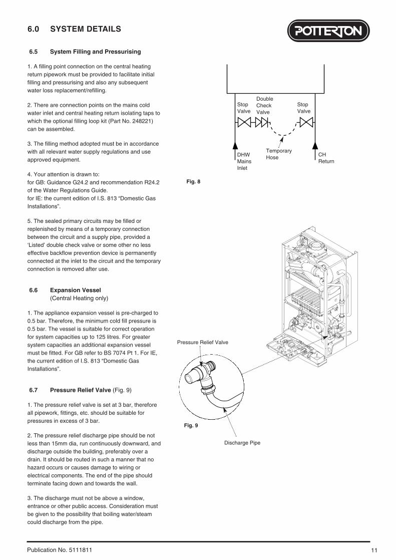
6.5 System Filling and Pressurising
1. A filling point connection on the central heatingreturn pipework must be provided to facilitate initialfilling and pressurising and also any subsequentwater loss replacement/refilling.
2. There are connection points on the mains coldwater inlet and central heating return isolating taps towhich the optional filling loop kit (Part No. 248221)can be assembled.
3. The filling method adopted must be in accordancewith all relevant water supply regulations and useapproved equipment.
4. Your attention is drawn to: for GB: Guidance G24.2 and recommendation R24.2of the Water Regulations Guide. for IE: the current edition of I.S. 813 “Domestic GasInstallations”.
5. The sealed primary circuits may be filled orreplenished by means of a temporary connectionbetween the circuit and a supply pipe, provided a‘Listed’ double check valve or some other no lesseffective backflow prevention device is permanentlyconnected at the inlet to the circuit and the temporaryconnection is removed after use.
6.6 Expansion Vessel (Central Heating only)
1. The appliance expansion vessel is pre-charged to0.5 bar. Therefore, the minimum cold fill pressure is0.5 bar. The vessel is suitable for correct operationfor system capacities up to 125 litres. For greatersystem capacities an additional expansion vesselmust be fitted. For GB refer to BS 7074 Pt 1. For IE,the current edition of I.S. 813 “Domestic GasInstallations”.
6.7 Pressure Relief Valve (Fig. 9)
1. The pressure relief valve is set at 3 bar, thereforeall pipework, fittings, etc. should be suitable forpressures in excess of 3 bar.
2. The pressure relief discharge pipe should be notless than 15mm dia, run continuously downward, anddischarge outside the building, preferably over adrain. It should be routed in such a manner that nohazard occurs or causes damage to wiring orelectrical components. The end of the pipe shouldterminate facing down and towards the wall.
3. The discharge must not be above a window,entrance or other public access. Consideration mustbe given to the possibility that boiling water/steamcould discharge from the pipe.
Fig. 8
Fig. 9
StopValve
DoubleCheckValve
DHWMainsInlet
CHReturn
TemporaryHose
Pressure Relief Valve
Discharge Pipe
StopValve
6.0 SYSTEM DETAILS
12 Publication No. 5111811
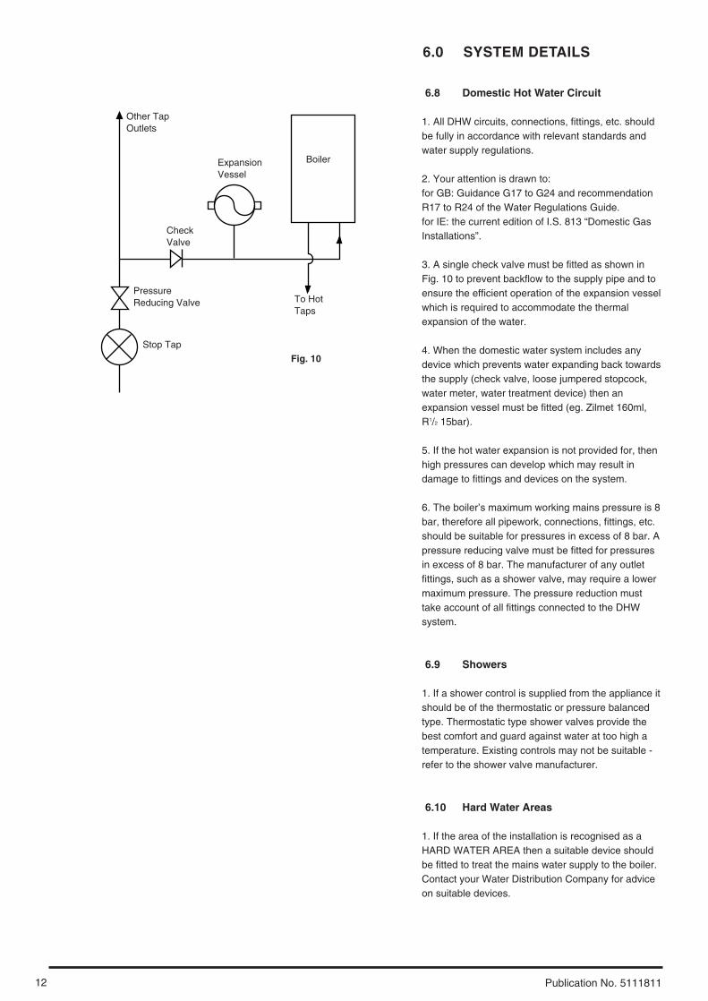
6.8 Domestic Hot Water Circuit
1. All DHW circuits, connections, fittings, etc. shouldbe fully in accordance with relevant standards andwater supply regulations.
2. Your attention is drawn to: for GB: Guidance G17 to G24 and recommendationR17 to R24 of the Water Regulations Guide.for IE: the current edition of I.S. 813 “Domestic GasInstallations”.
3. A single check valve must be fitted as shown inFig. 10 to prevent backflow to the supply pipe and toensure the efficient operation of the expansion vesselwhich is required to accommodate the thermalexpansion of the water.
4. When the domestic water system includes anydevice which prevents water expanding back towardsthe supply (check valve, loose jumpered stopcock,water meter, water treatment device) then anexpansion vessel must be fitted (eg. Zilmet 160ml,R1/2 15bar).
5. If the hot water expansion is not provided for, thenhigh pressures can develop which may result indamage to fittings and devices on the system.
6. The boiler’s maximum working mains pressure is 8bar, therefore all pipework, connections, fittings, etc.should be suitable for pressures in excess of 8 bar. Apressure reducing valve must be fitted for pressuresin excess of 8 bar. The manufacturer of any outletfittings, such as a shower valve, may require a lowermaximum pressure. The pressure reduction musttake account of all fittings connected to the DHWsystem.
6.9 Showers
1. If a shower control is supplied from the appliance itshould be of the thermostatic or pressure balancedtype. Thermostatic type shower valves provide thebest comfort and guard against water at too high atemperature. Existing controls may not be suitable -refer to the shower valve manufacturer.
6.10 Hard Water Areas
1. If the area of the installation is recognised as aHARD WATER AREA then a suitable device shouldbe fitted to treat the mains water supply to the boiler.Contact your Water Distribution Company for adviceon suitable devices.
Boiler
Other TapOutlets
ExpansionVessel
To HotTaps
CheckValve
PressureReducing Valve
Stop Tap
Fig. 10
13
7.0 SITE REQUIREMENTS
Publication No. 5111811
7.1 Location
1. The boiler may be fitted to any suitable wall with theflue passing through an outside wall or roof anddischarging to atmosphere in a position permittingsatisfactory removal of combustion products andproviding an adequate air supply. The boiler should befitted within the building unless otherwise protected bya suitable enclosure i.e. garage or outhouse. (Theboiler may be fitted inside a cupboard - see Section7.3).
2. If the boiler is sited in an unheated enclosure then itis recommended that frost protection is incorporated inthe control system.
3. If the boiler is fitted in a room containing a bath orshower reference must be made to the relevantrequirements.In GB this is the current I.E.E. Wiring Regulations andBuilding Regulations.In IE reference should be made to the current editionof I.S. 813 “Domestic Gas Installations” and thecurrent ETCI rules.
4. If the boiler is to be fitted into a building of timberframe construction then reference must be made tothe current edition of Institute of Gas EngineersPublication IGE/UP/7 (Gas Installations in TimberFramed Housing).
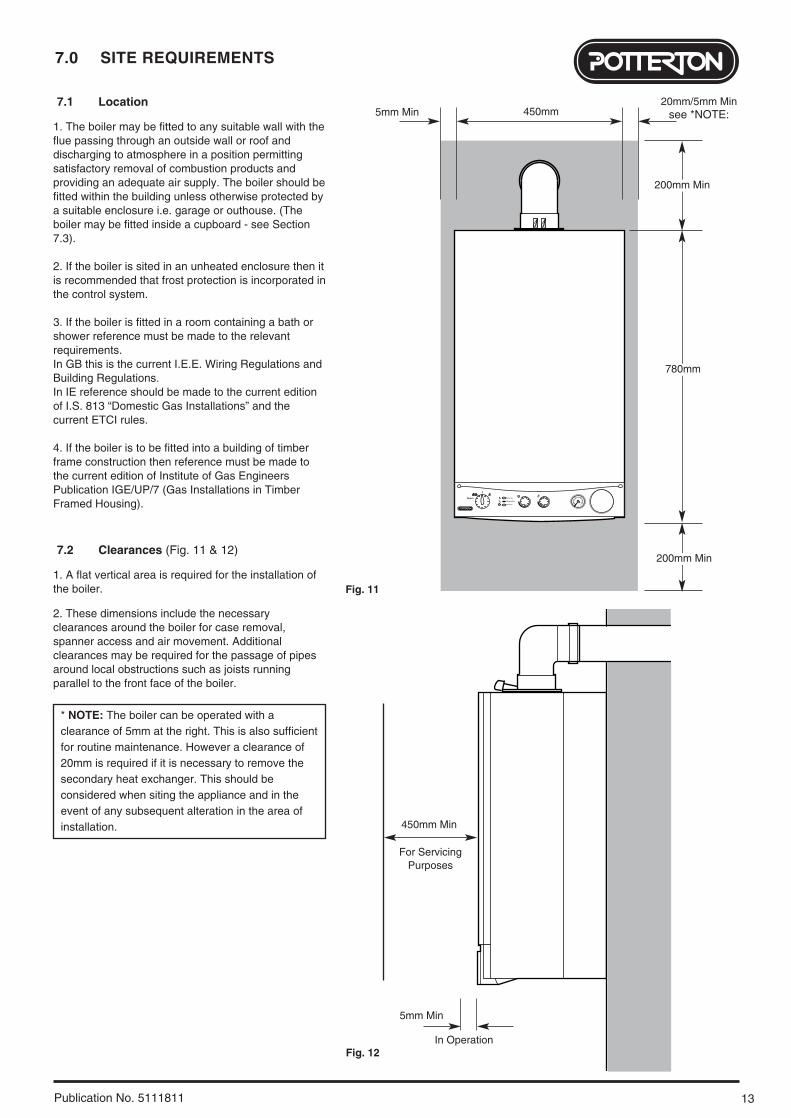
7.2 Clearances (Fig. 11 & 12)
1. A flat vertical area is required for the installation ofthe boiler.
2. These dimensions include the necessaryclearances around the boiler for case removal,spanner access and air movement. Additionalclearances may be required for the passage of pipesaround local obstructions such as joists runningparallel to the front face of the boiler.
* NOTE: The boiler can be operated with aclearance of 5mm at the right. This is also sufficientfor routine maintenance. However a clearance of20mm is required if it is necessary to remove thesecondary heat exchanger. This should beconsidered when siting the appliance and in theevent of any subsequent alteration in the area ofinstallation.
2
1
0 4
3
bar
Reset Burner On
Flame Failure
Power On
200mm Min
780mm
450mm
200mm Min
20mm/5mm Minsee *NOTE:5mm Min
5mm Min
450mm Min
For ServicingPurposes
Fig. 11
Fig. 12In Operation

7.0 SITE REQUIREMENTS
14 Publication No. 5111811
7.3 Ventilation of Compartments
1. Where the appliance is installed in a cupboard orcompartment, no air vents are required.
2. BS 5440: Part 2 refers to room sealed appliancesinstalled in compartments. The appliance will runsufficiently cool without ventilation.
7.4 Gas Supply
1. The gas installation should be in accordance withthe relevant standards. In GB this is BS 6891. In IEthis is the current edition of I.S. 813 “Domestic GasInstallations”.
2. The connection to the appliance is a 22mmcopper tail located at the rear of the gas service cock(Fig. 13).
3. Ensure that the pipework from the meter to theappliance is of adequate size. Do not use pipes of asmaller diameter than the boiler gas connection(22mm).
7.5 Electrical Supply
1. External wiring must be correctly earthed,polarised and in accordance with relevantregulations/rules. In GB this is the current I.E.E.Wiring Regulations. In IE reference should be madeto the current edition of ETCI rules.
2. The mains supply is 230V ~ 50Hz fused at 3Amaximum.
NOTE: The method of connection to theelectricity supply must facilitate completeelectrical isolation of the appliance.
Connection may be via a fused double-poleisolator with a contact separation of at least 3mmin all poles and servicing the boiler and systemcontrols only.
Fig. 13
Gas Service Cock
15
7.0 SITE REQUIREMENTS
Publication No. 5111811
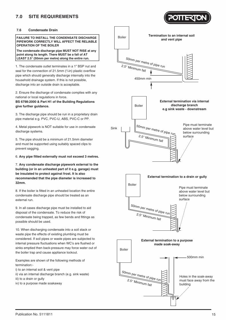
7.6 Condensate Drain
FAILURE TO INSTALL THE CONDENSATE DISCHARGEPIPEWORK CORRECTLY WILL AFFECT THE RELIABLEOPERATION OF THE BOILER
The condensate discharge pipe MUST NOT RISE at anypoint along its length. There MUST be a fall of ATLEAST 2.5° (50mm per metre) along the entire run.
1. The condensate outlet terminates in a 1” BSP nut andseal for the connection of 21.5mm (3/4in) plastic overflowpipe which should generally discharge internally into thehousehold drainage system. If this is not possible,discharge into an outside drain is acceptable.
2. Ensure the discharge of condensate complies with anynational or local regulations in force. BS 6798:2000 & Part H1 of the Building Regulationsgive further guidance.
3. The discharge pipe should be run in a proprietary drainpipe material e.g. PVC, PVC-U, ABS, PVC-C or PP.
4. Metal pipework is NOT suitable for use in condensatedischarge systems.
5. The pipe should be a minimum of 21.5mm diameterand must be supported using suitably spaced clips toprevent sagging.
6. Any pipe fitted externally must not exceed 3 metres.
7. Any condensate discharge pipework external to thebuilding (or in an unheated part of it e.g. garage) mustbe insulated to protect against frost. It is alsorecommended that the pipe diameter is increased to32mm.
8. If the boiler is fitted in an unheated location the entirecondensate discharge pipe should be treated as anexternal run.
9. In all cases discharge pipe must be installed to aiddisposal of the condensate. To reduce the risk ofcondensate being trapped, as few bends and fittings aspossible should be used.
10. When discharging condensate into a soil stack orwaste pipe the effects of existing plumbing must beconsidered. If soil pipes or waste pipes are subjected tointernal pressure fluctuations when WC's are flushed orsinks emptied then back-pressure may force water out ofthe boiler trap and cause appliance lockout.
Examples are shown of the following methods oftermination:-i) to an internal soil & vent pipeii) via an internal discharge branch (e.g. sink waste)iii) to a drain or gullyiv) to a purpose made soakaway
Boiler
2.5° Minimum fall
Termination to an internal soiland vent pipe
450mm min
Boiler
2.5° Minimum fall
External termination via internaldischarge branch
e.g sink waste - downstream
SinkPipe must terminateabove water level butbelow surroundingsurface
BoilerPipe must terminateabove water level butbelow surroundingsurface
2.5° Minimum fall
External termination to a drain or gully
Boiler
500mm min
2.5° Minimum fall
External termination to a purposemade soak-away
Holes in the soak-awaymust face away from thebuilding
50mm per metre of pipe run
50mm per metre of pipe run
50mm per metre of pipe run
50mm per metre of pipe run
7.0 SITE REQUIREMENTS
16 Publication No. 5111811
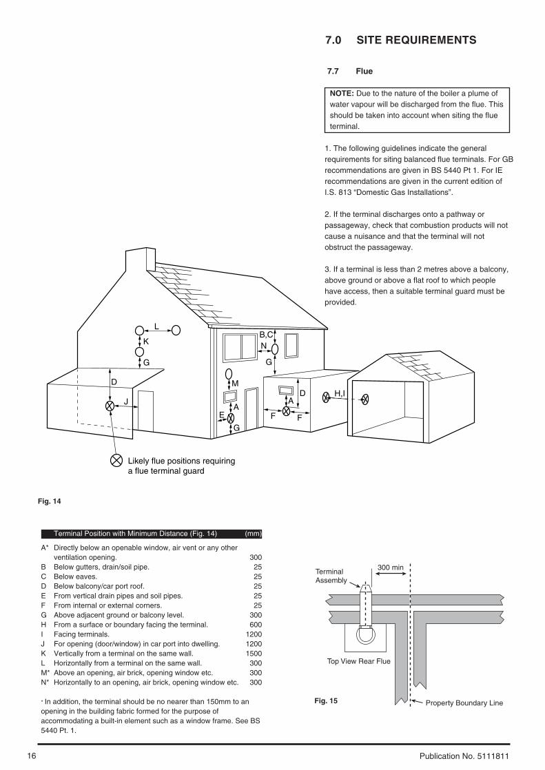
7.7 Flue
NOTE: Due to the nature of the boiler a plume ofwater vapour will be discharged from the flue. Thisshould be taken into account when siting the flueterminal.
1. The following guidelines indicate the generalrequirements for siting balanced flue terminals. For GBrecommendations are given in BS 5440 Pt 1. For IErecommendations are given in the current edition ofI.S. 813 “Domestic Gas Installations”.
2. If the terminal discharges onto a pathway orpassageway, check that combustion products will notcause a nuisance and that the terminal will notobstruct the passageway.
3. If a terminal is less than 2 metres above a balcony,above ground or above a flat roof to which peoplehave access, then a suitable terminal guard must beprovided.
Terminal Position with Minimum Distance (Fig. 14) (mm)
A* Directly below an openable window, air vent or any otherventilation opening. 300
B Below gutters, drain/soil pipe. 25C Below eaves. 25D Below balcony/car port roof. 25E From vertical drain pipes and soil pipes. 25F From internal or external corners. 25G Above adjacent ground or balcony level. 300H From a surface or boundary facing the terminal. 600I Facing terminals. 1200J For opening (door/window) in car port into dwelling. 1200K Vertically from a terminal on the same wall. 1500L Horizontally from a terminal on the same wall. 300M* Above an opening, air brick, opening window etc. 300N* Horizontally to an opening, air brick, opening window etc. 300
* In addition, the terminal should be no nearer than 150mm to anopening in the building fabric formed for the purpose ofaccommodating a built-in element such as a window frame. See BS5440 Pt. 1.
Fig. 14
L
G
G
E
J
D
K
G
AA
D
F
H,I
B,C
F
Likely flue positions requiring a flue terminal guard
M
N
300 minTerminalAssembly
Top View Rear Flue
Property Boundary LineFig. 15
17
7.0 SITE REQUIREMENTS
Publication No. 5111811
Fig. 17
Fig. 16
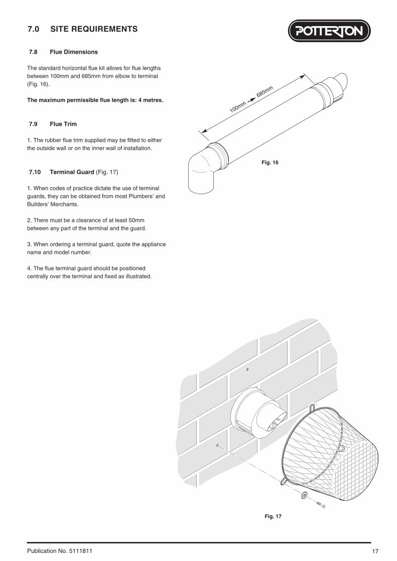
7.8 Flue Dimensions
The standard horizontal flue kit allows for flue lengthsbetween 100mm and 685mm from elbow to terminal(Fig. 16).
The maximum permissible flue length is: 4 metres.
7.9 Flue Trim
1. The rubber flue trim supplied may be fitted to eitherthe outside wall or on the inner wall of installation.
7.10 Terminal Guard (Fig. 17)
1. When codes of practice dictate the use of terminalguards, they can be obtained from most Plumbers’ andBuilders’ Merchants.
2. There must be a clearance of at least 50mmbetween any part of the terminal and the guard.
3. When ordering a terminal guard, quote the appliancename and model number.
4. The flue terminal guard should be positionedcentrally over the terminal and fixed as illustrated.
100mm
685mm
7.0 SITE REQUIREMENTS
18 Publication No. 5111811
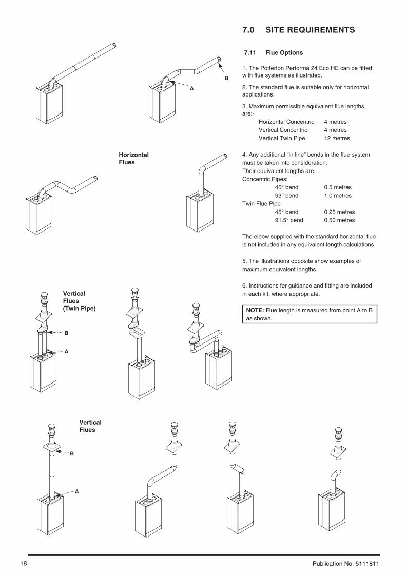
7.11 Flue Options
1. The Potterton Performa 24 Eco HE can be fittedwith flue systems as illustrated.
2. The standard flue is suitable only for horizontalapplications.
3. Maximum permissible equivalent flue lengthsare:-
Horizontal Concentric 4 metresVertical Concentric 4 metresVertical Twin Pipe 12 metres
4. Any additional “in line” bends in the flue systemmust be taken into consideration. Their equivalent lengths are:-Concentric Pipes:
45° bend 0.5 metres93° bend 1.0 metres
Twin Flue Pipe45° bend 0.25 metres91.5° bend 0.50 metres
The elbow supplied with the standard horizontal flueis not included in any equivalent length calculations
5. The illustrations opposite show examples ofmaximum equivalent lengths.
6. Instructions for guidance and fitting are includedin each kit, where appropriate.
NOTE: Flue length is measured from point A to Bas shown.
HorizontalFlues
VerticalFlues
VerticalFlues(Twin Pipe)
B
A
B
A
B
A
19
8.0 INSTALLATION
Publication No. 5111811
8.1 Initial Preparation
The gas supply, gas type and pressure must bechecked for suitability before connection (seeSection 7.4).
1. After considering the site requirements (see Section 7.0) position the fixing template on thewall ensuring it is level both horizontally andvertically.
2. Mark the position of the two most suitable fixingslots for the wall plate and boiler lower fixing holes. Itis preferable to use the horizontal fixing slots. Forside flue exit, mark as shown (Fig. 18).
3. Mark the position of the centre of the flue hole (rearexit). For side flue exit, mark as shown.
4. If required, mark the position of the gas and waterpipes. Remove the template.
5. Cut the hole for the flue (minimum diameter116mm).
6. Drill the wall as previously marked to accept thewall plugs supplied. Secure the wall plate using twoof the fixing screws.
7. Using a spirit level ensure that the plate is levelbefore finally tightening the screws.
8.2 Flushing
1. Connect a tube to the central heating flow or returnpipe (Fig. 19).
2. Flush thoroughly (see System Details, Section6.2).
8.3 Preparing The Boiler
1. Remove all packaging.
2. Stand the boiler on its base by using the rear loweredge as a pivot.
NOTE: A small amount of water may drain from theboiler in the upright position.
Fig. 18
Fig. 19
190mm
For Side Flue Exit
Central Heating Return
Flushing Tube
8.0 INSTALLATION
20 Publication No. 5111811
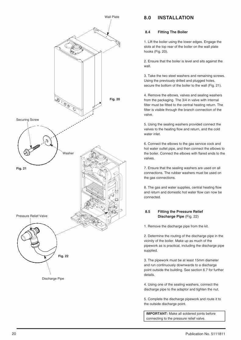
8.4 Fitting The Boiler
1. Lift the boiler using the lower edges. Engage theslots at the top rear of the boiler on the wall platehooks (Fig. 20).
2. Ensure that the boiler is level and sits against thewall.
3. Take the two steel washers and remaining screws.Using the previously drilled and plugged holes,secure the bottom of the boiler to the wall (Fig. 21).
4. Remove the elbows, valves and sealing washersfrom the packaging. The 3/4 in valve with internalfilter must be fitted to the central heating return. Thefilter is visible through the branch connection of thevalve.
5. Using the sealing washers provided connect thevalves to the heating flow and return, and the coldwater inlet.
6. Connect the elbows to the gas service cock andhot water outlet pipe, and then connect the elbows tothe boiler. Connect the elbows with flared ends to thevalves.
7. Ensure that the sealing washers are used on allconnections. The rubber washers must be used onthe gas connections.
8. The gas and water supplies, central heating flowand return and domestic hot water flow can now beconnected.
8.5 Fitting the Pressure Relief Discharge Pipe (Fig. 22)
1. Remove the discharge pipe from the kit.
2. Determine the routing of the discharge pipe in thevicinity of the boiler. Make up as much of thepipework as is practical, including the discharge pipesupplied.
3. The pipework must be at least 15mm diameterand run continuously downwards to a dischargepoint outside the building. See section 6.7 for furtherdetails.
4. Using one of the sealing washers, connect thedischarge pipe to the adaptor and tighten the nut.
5. Complete the discharge pipework and route it tothe outside discharge point.
IMPORTANT: Make all soldered joints beforeconnecting to the pressure relief valve.
Fig. 22
Fig. 20
Fig. 21
Pressure Relief Valve
Securing Screw
Washer
Wall Plate
Discharge Pipe

21
8.0 INSTALLATION
Publication No. 5111811
8.6 Condensate Drain (see section 7.6)
1. Connect the condensate drain using the 1” BSP nutand seal supplied.
Ensure the discharge of condensate complies withany national or local regulations in force (seeBritish Gas “Guidance Notes for the Installation ofDomestic Gas Condensing Boilers”.
2. The condensate outlet terminates in a 1” BSP nutand seal for the connection of 21.5mm (3/4in) plasticoverflow pipe which should generally dischargeinternally into the household drainage system. If thisis not possible, discharge into an outside drain isacceptable.
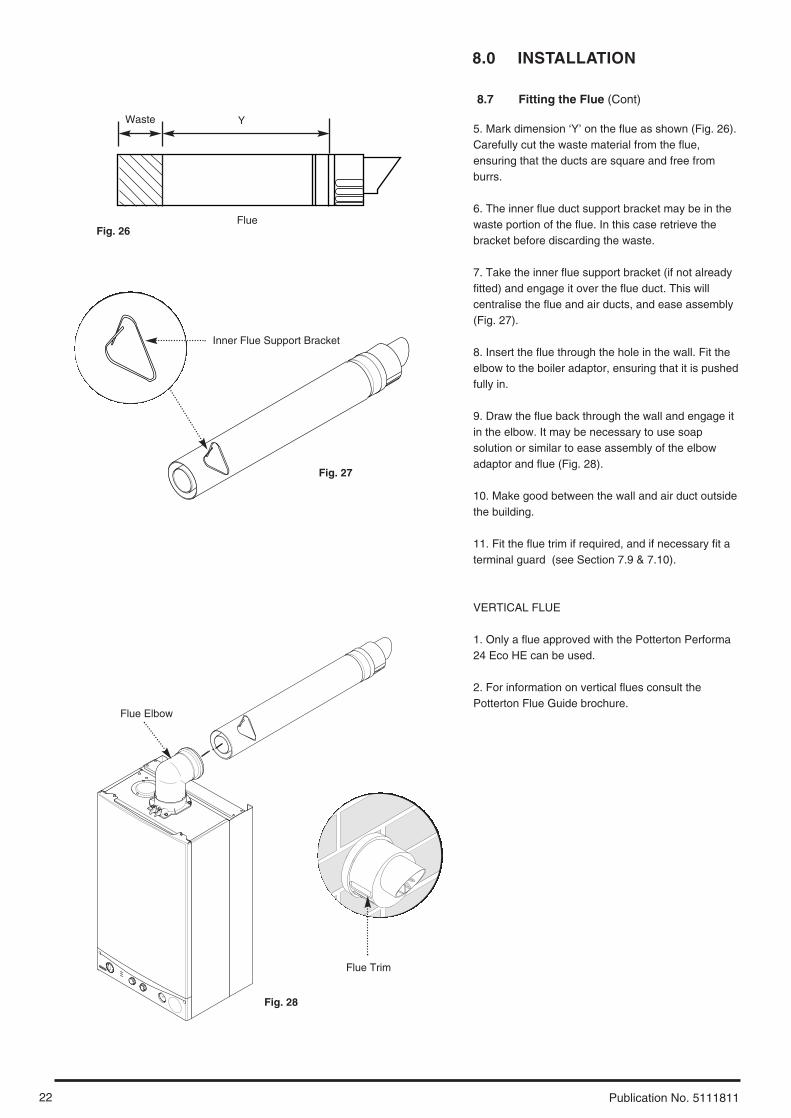
8.7 Fitting The Flue
HORIZONTAL FLUE
1. The standard flue is suitable for lengths between100mm minimum and 685mm maximum, asmeasured from the edge of the flue elbow outlet tothe joint between the terminal and air duct (Fig. 23).
2. Locate the flue elbow on the adaptor at the top ofthe boiler. Set the elbow to the required orientation(Fig. 24).
NOTE: The flue elbow is angled at 93 degrees toensure a fall back to the boiler.
3. Measure the distance from the outside wall face tothe elbow. This dimension will be known as ‘X’ (Fig. 25).
4. To dimension ‘X’ add 50mm. This dimension to beknown as ‘Y’.
IMPORTANT: Check all dimensions before cutting.
Wall Thickness
(X)
Wall Thickness
(X)
Flue Elbow
Fig. 25
100mm
685mm
Fig. 23
Fig. 24
Adaptor
8.0 INSTALLATION
22 Publication No. 5111811
8.7 Fitting the Flue (Cont)
5. Mark dimension ‘Y’ on the flue as shown (Fig. 26).Carefully cut the waste material from the flue,ensuring that the ducts are square and free fromburrs.
6. The inner flue duct support bracket may be in thewaste portion of the flue. In this case retrieve thebracket before discarding the waste.
7. Take the inner flue support bracket (if not alreadyfitted) and engage it over the flue duct. This willcentralise the flue and air ducts, and ease assembly(Fig. 27).
8. Insert the flue through the hole in the wall. Fit theelbow to the boiler adaptor, ensuring that it is pushedfully in.
9. Draw the flue back through the wall and engage itin the elbow. It may be necessary to use soapsolution or similar to ease assembly of the elbowadaptor and flue (Fig. 28).
10. Make good between the wall and air duct outsidethe building.
11. Fit the flue trim if required, and if necessary fit aterminal guard (see Section 7.9 & 7.10).
VERTICAL FLUE
1. Only a flue approved with the Potterton Performa24 Eco HE can be used.
2. For information on vertical flues consult thePotterton Flue Guide brochure.
Flue Trim
Inner Flue Support Bracket
Y
Flue
Waste
Flue Elbow
Fig. 26
Fig. 27
Fig. 28
23
8.0 INSTALLATION
Publication No. 5111811
L230 V
Selector / Reset Switch
ExternalControls Nbr b
Pump
Hydraulic Differential Pressure Switchr
r
DHW Flow Priority Microswitchg
g
Safety Overheat Thermostat
Flue Thermostatb
b
NTC Sensorr
r
Gas ValveSpark Electrode
Condensate Trap
Flame Sensing Electrode
Nbr b
Fan
bkbk
bbrbk
Pressure Switchbbr
PCB
b
bbr
r
bk
bk
br
Gas Valve Modulator
Fig. 31
Fig. 30
Fig. 32
Fig. 33
Fig. 29
Cable Clamp
Control Box Cover
Facia Panel
Functional Flow Diagram
Key to Wiringb - bluebr - brownbk - blackr - redg - greenw - white
Always fit fast blow 2A fuse
Fused supply 3A230V ~ 50Hz
Live (brown)
Neutral (blue)
Earth (green/yellow)
1
2
230V
br
b
g/y
bk
bk
b
br
bk
bk
g/y
1
N
L
Frost Thermostat
Room Thermostat
External Clock
2N
230 V
NL
SL
Terminal Block
Fuse
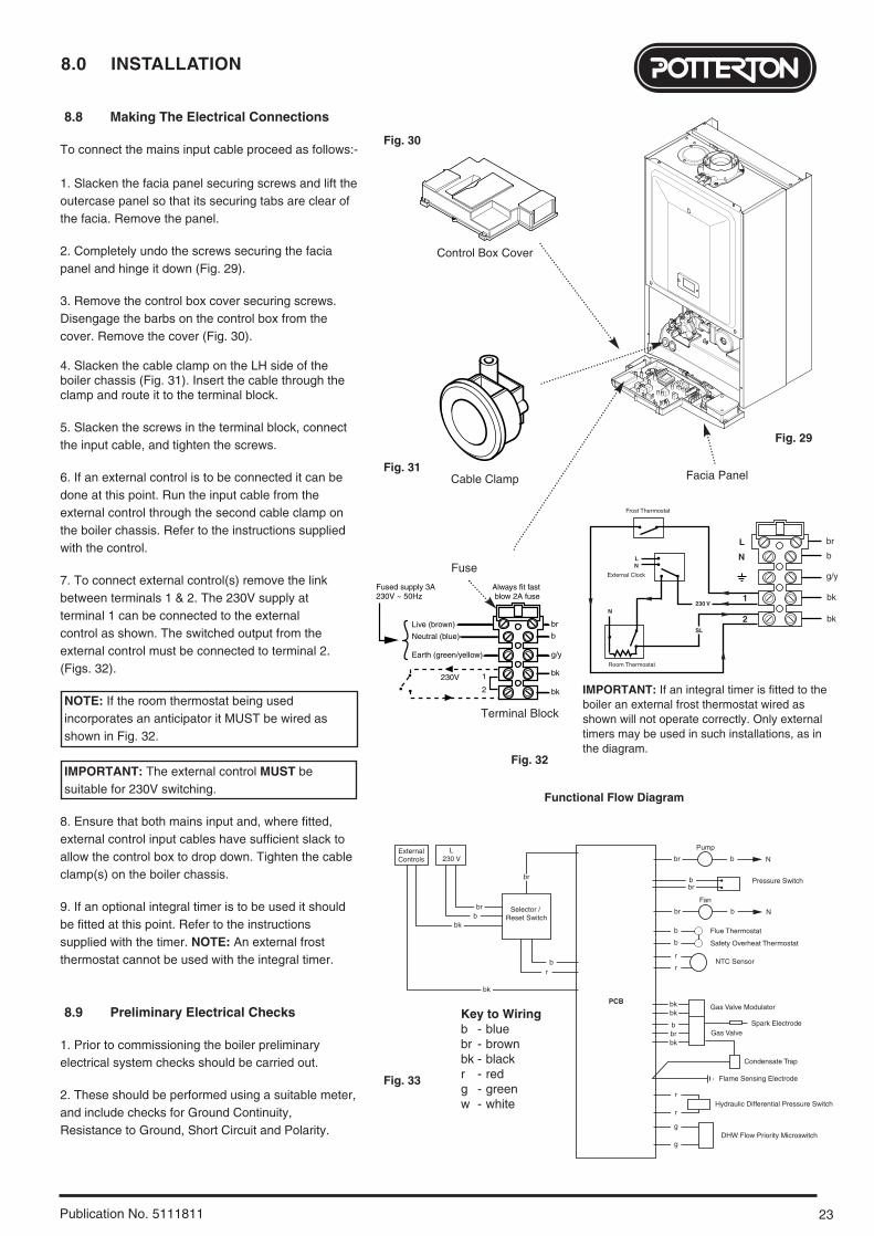
8.8 Making The Electrical Connections
To connect the mains input cable proceed as follows:-
1. Slacken the facia panel securing screws and lift theoutercase panel so that its securing tabs are clear ofthe facia. Remove the panel.
2. Completely undo the screws securing the faciapanel and hinge it down (Fig. 29).
3. Remove the control box cover securing screws.Disengage the barbs on the control box from thecover. Remove the cover (Fig. 30).
4. Slacken the cable clamp on the LH side of theboiler chassis (Fig. 31). Insert the cable through theclamp and route it to the terminal block.
5. Slacken the screws in the terminal block, connectthe input cable, and tighten the screws.
6. If an external control is to be connected it can bedone at this point. Run the input cable from theexternal control through the second cable clamp onthe boiler chassis. Refer to the instructions suppliedwith the control.
7. To connect external control(s) remove the link between terminals 1 & 2. The 230V supply at terminal 1 can be connected to the external control as shown. The switched output from theexternal control must be connected to terminal 2.(Figs. 32).
NOTE: If the room thermostat being usedincorporates an anticipator it MUST be wired asshown in Fig. 32.
IMPORTANT: The external control MUST besuitable for 230V switching.
8. Ensure that both mains input and, where fitted,external control input cables have sufficient slack toallow the control box to drop down. Tighten the cableclamp(s) on the boiler chassis.
9. If an optional integral timer is to be used it shouldbe fitted at this point. Refer to the instructionssupplied with the timer. NOTE: An external frostthermostat cannot be used with the integral timer.
8.9 Preliminary Electrical Checks
1. Prior to commissioning the boiler preliminaryelectrical system checks should be carried out.
2. These should be performed using a suitable meter,and include checks for Ground Continuity,Resistance to Ground, Short Circuit and Polarity.
IMPORTANT: If an integral timer is fitted to theboiler an external frost thermostat wired asshown will not operate correctly. Only externaltimers may be used in such installations, as inthe diagram.
9.0 COMMISSIONING
24 Publication No. 5111811
9.1 Commissioning the Boiler
1. Reference should be made to BS 5449 Section 5when commissioning the boiler.
2. Open the mains water supply to the boiler.
3. Open all hot water taps to purge the DHW system.
4. Ensure that the filling loop is connected and open,then open the heating flow and return valves on theboiler.
5. Open the screw on the automatic air vent (Fig. 35).
6. The system must be flushed in accordance withBS 7593 (see Section 6.2) and the flushing agentmanufacturers instructions.
7. Pressurise the system to at least 0.5 bar thenclose and disconnect the filling loop (Fig. 34).
8. Turn the gas supply on and purge the systemaccording to in GB BS 6891 and in IE I.S. 813“Domestic Gas Installations”.
9. Test for gas soundness.
10. If at any time during commissioning it is requiredto terminate a particular cycle, turn the selector to theOFF position and then back to either ( ) or ( )(Fig. 36).
Automatic Air Vent
Pressure Gauge
Screw
2
1
0 4
3
bar
Selector Switch
Central Heating Temperature Control
Hot Water Temperature Control
Fig. 35
Fig. 36
Fig. 34
2
1
0 4
3
bar
Reset Burner On
Flame Failure
Power On
Performa 24 Eco HE
25
9.0 COMMISSIONING
Publication No. 5111811
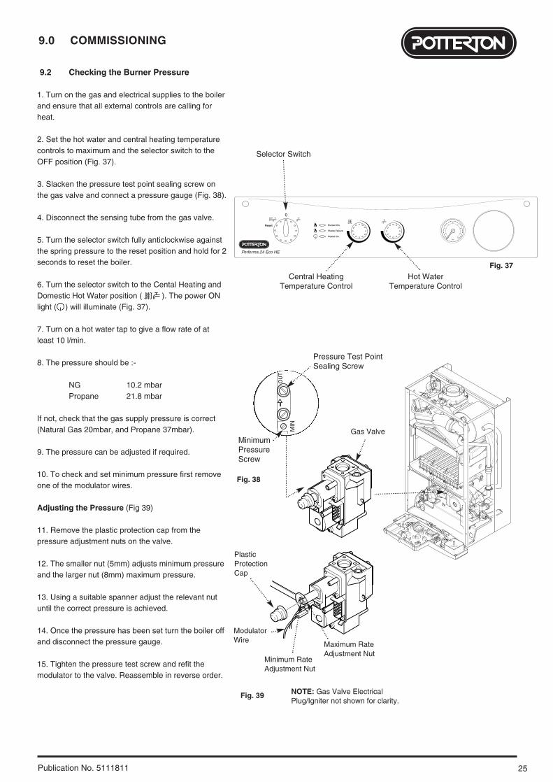
9.2 Checking the Burner Pressure
1. Turn on the gas and electrical supplies to the boilerand ensure that all external controls are calling forheat.
2. Set the hot water and central heating temperaturecontrols to maximum and the selector switch to theOFF position (Fig. 37).
3. Slacken the pressure test point sealing screw onthe gas valve and connect a pressure gauge (Fig. 38).
4. Disconnect the sensing tube from the gas valve.
5. Turn the selector switch fully anticlockwise againstthe spring pressure to the reset position and hold for 2seconds to reset the boiler.
6. Turn the selector switch to the Cental Heating andDomestic Hot Water position ( ). The power ONlight ( ) will illuminate (Fig. 37).
7. Turn on a hot water tap to give a flow rate of atleast 10 l/min.
8. The pressure should be :-
NG 10.2 mbarPropane 21.8 mbar
If not, check that the gas supply pressure is correct(Natural Gas 20mbar, and Propane 37mbar).
9. The pressure can be adjusted if required.
10. To check and set minimum pressure first removeone of the modulator wires.
Adjusting the Pressure (Fig 39)
11. Remove the plastic protection cap from thepressure adjustment nuts on the valve.
12. The smaller nut (5mm) adjusts minimum pressureand the larger nut (8mm) maximum pressure.
13. Using a suitable spanner adjust the relevant nutuntil the correct pressure is achieved.
14. Once the pressure has been set turn the boiler offand disconnect the pressure gauge.
15. Tighten the pressure test screw and refit themodulator to the valve. Reassemble in reverse order.
OU
T
MIN
Pressure Test Point Sealing Screw
Central Heating Temperature Control
Hot Water Temperature Control
Fig. 37
Fig. 38
Fig. 39
2
1
0 4
3
bar
Reset Burner On
Flame Failure
Power On
Performa 24 Eco HE
Selector Switch
MinimumPressureScrew
Gas Valve
PlasticProtectionCap
ModulatorWire
Maximum RateAdjustment Nut
Minimum RateAdjustment Nut
NOTE: Gas Valve ElectricalPlug/Igniter not shown for clarity.

10.0 COMPLETION
26 Publication No. 5111811
10.1 Completion
1. Hinge the facia panel upwards and engage thesecuring screws. Refit the case front panel andtighten the screws (Fig. 40).
2. Instruct the user in the operation of the boiler andsystem, explaining the operational sequence.
3. Carefully read and complete all sections of the“Benchmark” Installation, Commissioning andService Record Log Book that are relevant to theappliance and installation. The details of the LogBook will be required in the event of any warrantywork. The Log Book must be handed to the user forsafe keeping and each subsequent regular servicevisit recorded.
4. For IE, it is necessary to complete a “Declarationof Conformity” to indicate compliance with I.S. 813.An example of this is given in I.S. 813 “DomesticGas Installations”. In addition it is necessary tocomplete the “Benchmark” Log Book.
5. Hand over the Users Operating, Installation andServicing Instructions and the Log Book, givingadvice on the necessity of regular servicing.
Fig. 40
Facia Panel
Case Front Panel
27
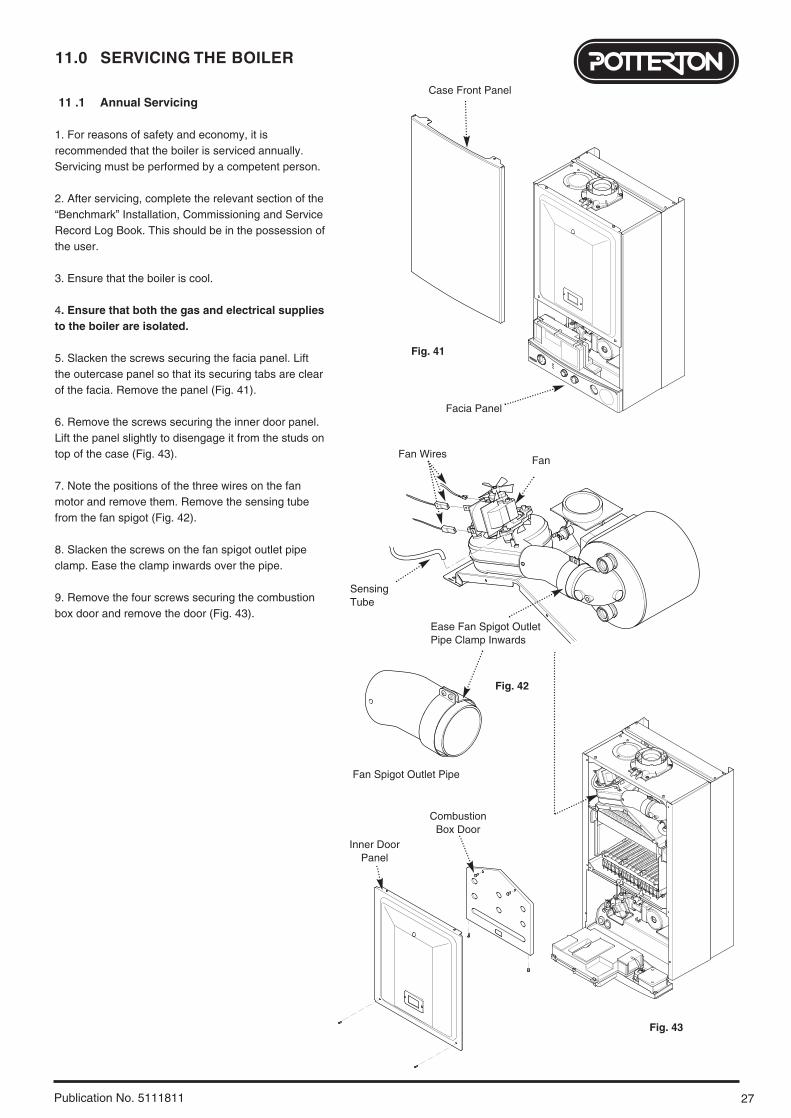
11.0 SERVICING THE BOILER
Publication No. 5111811
11 .1 Annual Servicing
1. For reasons of safety and economy, it isrecommended that the boiler is serviced annually.Servicing must be performed by a competent person.
2. After servicing, complete the relevant section of the“Benchmark” Installation, Commissioning and ServiceRecord Log Book. This should be in the possession ofthe user.
3. Ensure that the boiler is cool.
4. Ensure that both the gas and electrical suppliesto the boiler are isolated.
5. Slacken the screws securing the facia panel. Liftthe outercase panel so that its securing tabs are clearof the facia. Remove the panel (Fig. 41).
6. Remove the screws securing the inner door panel.Lift the panel slightly to disengage it from the studs ontop of the case (Fig. 43).
7. Note the positions of the three wires on the fanmotor and remove them. Remove the sensing tubefrom the fan spigot (Fig. 42).
8. Slacken the screws on the fan spigot outlet pipeclamp. Ease the clamp inwards over the pipe.
9. Remove the four screws securing the combustionbox door and remove the door (Fig. 43).
Fig. 41
Fig. 43
Facia Panel
Case Front Panel
CombustionBox Door
Inner DoorPanel
Fan WiresFan
SensingTube
Ease Fan Spigot OutletPipe Clamp Inwards
Fan Spigot Outlet Pipe
Fig. 42

11.0 SERVICING THE BOILER
28 Publication No. 5111811
11.1 Annual Servicing (Cont)
10. Ease the front edge of the left hand baffleupwards, disengaging the spring clip. Disengage thetab on the baffle from the slot in the fan hood (Fig.44).
11. Undo the screws securing the fan hood assemblyto the appliance back panel, and draw the fan andhood assembly forwards (Fig. 45).
12. Draw the burner out of the combustion box, pullingthe electrode grommets from the slots in thecombustion box lower panel (Fig. 46).
13. Disconnect the electrode leads and grommetsfrom the electrodes. Completely remove the burner(Fig. 46).
14. Brush any deposits from the injectors. Do not usea pin or wire to clean them.
15. Brush the burner blades and venturis and cleanthe combustion box.
16. Ensure that the heat exchanger fins are clear ofany obstruction.
NOTE: If necessary the secondary heat exchangermay be dismantled - see section 12.23
D.H.W. Filters (Fig. 48)17. If the flow of domestic hot water is diminished, itmay be necessary to clean the filters.
18. Initially check the cold water inlet tap filter.
19. Turn the tap off. Undo the blanking cap andremove the threaded bush (Fig. 47).
20. Extract the filter and rinse thoroughly in cleanwater. Reassemble and check the flow. If requiredclean the manifold filter as described below.
21. Undo the filter cartridge from the inlet/returnmanifold.
22. Dismantle the cartridge and carefully remove theflow regulator and filter gauze. Rinse them thoroughlyin clean water and reassemble in reverse order.
23. Check that the pressure vessel charge is 0.5bar,reassemble in reverse order of dismantling.
24. Turn the selector switch fully anticlockwise againstthe spring pressure to position R and hold for 2seconds to reset the boiler before recommissioning.
25. Complete the relevant section of the “Benchmark”Installation, Commissioning and Service Record LogBook and hand it back to the user.
Burner
Electrode
Grommets
Electrode Leads
Inlet / Return Manifold
CartridgeBody
Filter Gauze
FlowRegulator
Venturi
Gas Supply Pipe
BlankingCap
Cold WaterInlet Tap
ThreadedBush
Fig. 46
Fig. 55
Fig. 48
Fig. 47
Spring Clip
Fan and HoodAssembly
BaffleTab
Fig. 44
Fig. 45
29
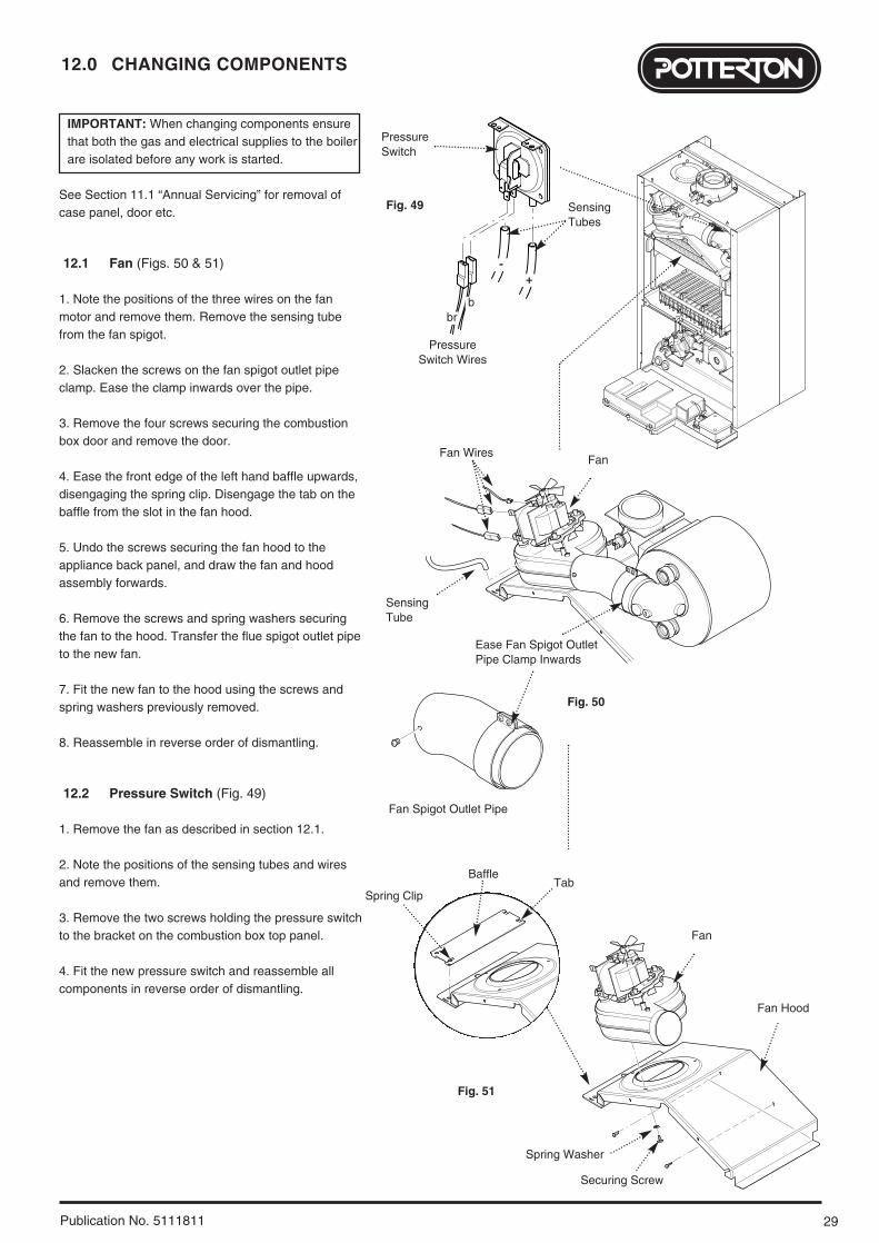
12.0 CHANGING COMPONENTS
Publication No. 5111811
IMPORTANT: When changing components ensurethat both the gas and electrical supplies to the boilerare isolated before any work is started.
See Section 11.1 “Annual Servicing” for removal ofcase panel, door etc.
12.1 Fan (Figs. 50 & 51)
1. Note the positions of the three wires on the fanmotor and remove them. Remove the sensing tubefrom the fan spigot.
2. Slacken the screws on the fan spigot outlet pipeclamp. Ease the clamp inwards over the pipe.
3. Remove the four screws securing the combustionbox door and remove the door.
4. Ease the front edge of the left hand baffle upwards,disengaging the spring clip. Disengage the tab on thebaffle from the slot in the fan hood.
5. Undo the screws securing the fan hood to theappliance back panel, and draw the fan and hoodassembly forwards.
6. Remove the screws and spring washers securingthe fan to the hood. Transfer the flue spigot outlet pipeto the new fan.
7. Fit the new fan to the hood using the screws andspring washers previously removed.
8. Reassemble in reverse order of dismantling.
12.2 Pressure Switch (Fig. 49)
1. Remove the fan as described in section 12.1.
2. Note the positions of the sensing tubes and wiresand remove them.
3. Remove the two screws holding the pressure switchto the bracket on the combustion box top panel.
4. Fit the new pressure switch and reassemble allcomponents in reverse order of dismantling.
PressureSwitch
SensingTubes
Pressure Switch Wires
Fig. 49
brb
-+
Fan Hood
Spring Washer
Securing Screw
Fan WiresFan
SensingTube
Ease Fan Spigot OutletPipe Clamp Inwards
Fan Spigot Outlet Pipe
Spring Clip
BaffleTab
Fan
Fig. 50
Fig. 51
12.0 CHANGING COMPONENTS
30 Publication No. 5111811
12.3 Heat Exchanger (Fig. 52)
1. Remove the fan as described in section 12.1.
2. Drain the primary circuit. Prise the pipe connectingclips off the joints in the flow and return pipes.Remove the heat exchanger return pipe.
3. Lift the heat exchanger to disconnect the flow pipejoint. Withdraw it from the appliance, taking care notto damage the rear insulation piece.
4. Fit the new heat exchanger, ensuring that the tabson the side insulation carriers engage in the slots inthe heat exchanger side plates.
5. Reassemble in reverse order of dismantling, andrepressurise the system.
12.4 Burner (Fig. 53)
1. Remove the four screws securing the combustionbox door and remove the door.
2. Draw the burner out of the combustion box, pullingthe electrode grommets from the slots in thecombustion box lower panel.
3. Disconnect the electrode leads and grommetsfrom the electrodes. Completely remove the burner.
4. Undo the screws securing the electrodes to theburner. Examine the condition of the electrodes,replacing if necessary. Fit the electrodes to the newburner.
5. Engage the burner location brackets over thestuds on the injector manifold and reassemble inreverse order.
Burner
ElectrodeGrommets
Electrode Leads
Electrodes
Pipe Connecting Clips
Heat Exchanger
Fig. 52
Fig. 53
31
12.0 CHANGING COMPONENTS
Publication No. 5111811
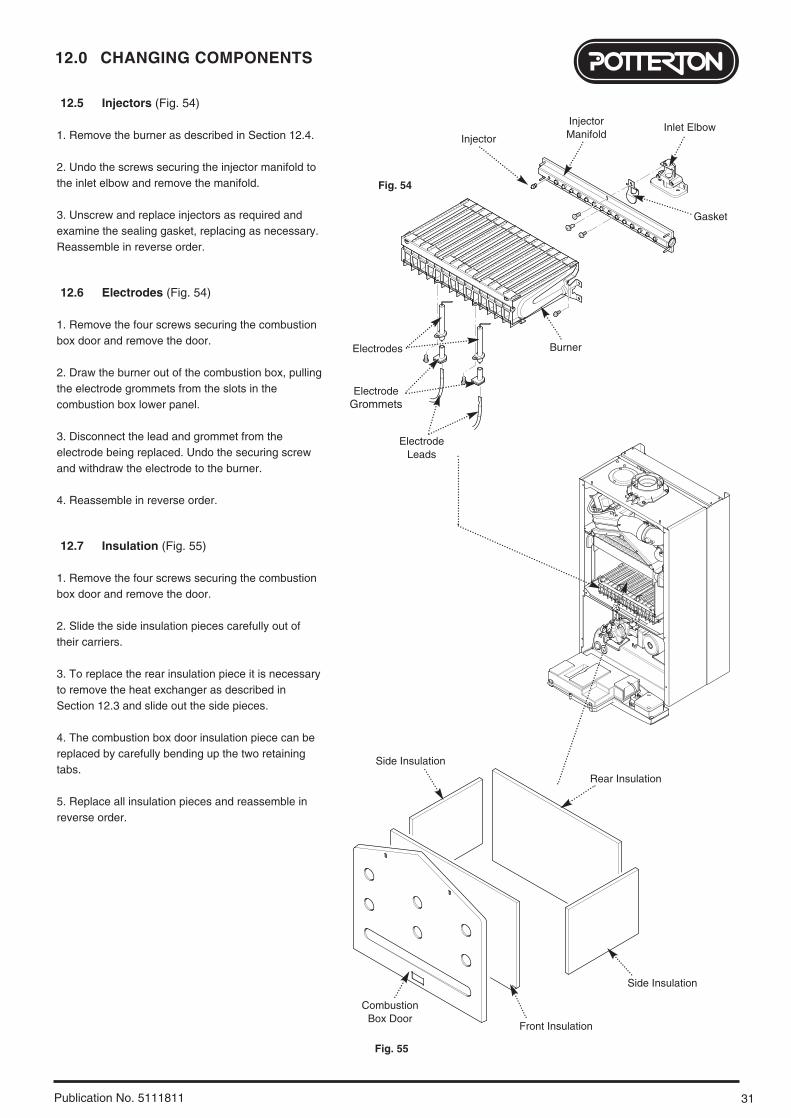
12.5 Injectors (Fig. 54)
1. Remove the burner as described in Section 12.4.
2. Undo the screws securing the injector manifold tothe inlet elbow and remove the manifold.
3. Unscrew and replace injectors as required andexamine the sealing gasket, replacing as necessary.Reassemble in reverse order.
12.6 Electrodes (Fig. 54)
1. Remove the four screws securing the combustionbox door and remove the door.
2. Draw the burner out of the combustion box, pullingthe electrode grommets from the slots in thecombustion box lower panel.
3. Disconnect the lead and grommet from theelectrode being replaced. Undo the securing screwand withdraw the electrode to the burner.
4. Reassemble in reverse order.
12.7 Insulation (Fig. 55)
1. Remove the four screws securing the combustionbox door and remove the door.
2. Slide the side insulation pieces carefully out oftheir carriers.
3. To replace the rear insulation piece it is necessaryto remove the heat exchanger as described inSection 12.3 and slide out the side pieces.
4. The combustion box door insulation piece can bereplaced by carefully bending up the two retainingtabs.
5. Replace all insulation pieces and reassemble inreverse order.
13.8
InjectorManifold
Inlet Elbow
Gasket
Injector
Burner
ElectrodeGrommets
Electrode Leads
Side Insulation
Rear Insulation
Front Insulation
CombustionBox Door
Side Insulation
Electrodes
Fig. 54
Fig. 55
12.0 CHANGING COMPONENTS
32 Publication No. 5111811
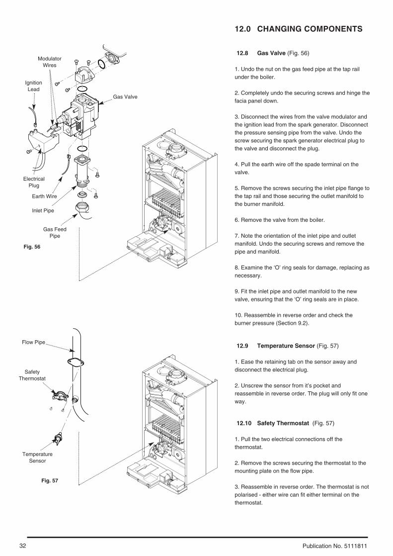
12.8 Gas Valve (Fig. 56)
1. Undo the nut on the gas feed pipe at the tap railunder the boiler.
2. Completely undo the securing screws and hinge thefacia panel down.
3. Disconnect the wires from the valve modulator andthe ignition lead from the spark generator. Disconnectthe pressure sensing pipe from the valve. Undo thescrew securing the spark generator electrical plug tothe valve and disconnect the plug.
4. Pull the earth wire off the spade terminal on thevalve.
5. Remove the screws securing the inlet pipe flange tothe tap rail and those securing the outlet manifold tothe burner manifold.
6. Remove the valve from the boiler.
7. Note the orientation of the inlet pipe and outletmanifold. Undo the securing screws and remove thepipe and manifold.
8. Examine the ‘O’ ring seals for damage, replacing asnecessary.
9. Fit the inlet pipe and outlet manifold to the newvalve, ensuring that the ‘O’ ring seals are in place.
10. Reassemble in reverse order and check theburner pressure (Section 9.2).
12.9 Temperature Sensor (Fig. 57)
1. Ease the retaining tab on the sensor away anddisconnect the electrical plug.
2. Unscrew the sensor from it’s pocket andreassemble in reverse order. The plug will only fit oneway.
12.10 Safety Thermostat (Fig. 57)
1. Pull the two electrical connections off thethermostat.
2. Remove the screws securing the thermostat to themounting plate on the flow pipe.
3. Reassemble in reverse order. The thermostat is notpolarised - either wire can fit either terminal on thethermostat.
Gas Valve
Inlet Pipe
Gas FeedPipe
ElectricalPlug
TemperatureSensor
SafetyThermostat
Flow Pipe
Fig. 56
Fig. 57
ModulatorWires
IgnitionLead
Earth Wire
33
12.0 CHANGING COMPONENTS
Publication No. 5111811
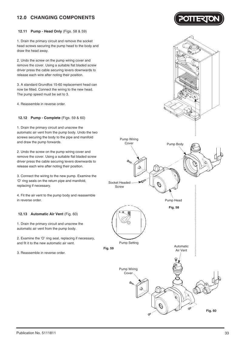
12.11 Pump - Head Only (Figs. 58 & 59)
1. Drain the primary circuit and remove the sockethead screws securing the pump head to the body anddraw the head away.
2. Undo the screw on the pump wiring cover andremove the cover. Using a suitable flat bladed screwdriver press the cable securing levers downwards torelease each wire after noting their position.
3. A standard Grundfos 15-60 replacement head cannow be fitted. Connect the wiring to the new head.The pump speed must be set to 3.
4. Reassemble in reverse order.
12.12 Pump - Complete (Figs. 59 & 60)
1. Drain the primary circuit and unscrew theautomatic air vent from the pump body. Undo the twoscrews securing the body to the pipe and manifoldand draw the pump forwards.
2. Undo the screw on the pump wiring cover andremove the cover. Using a suitable flat bladed screwdriver press the cable securing levers downwards torelease each wire after noting their position.
3. Connect the wiring to the new pump. Examine the‘O’ ring seals on the return pipe and manifold,replacing if necessary.
4. Fit the air vent to the pump body and reassemblein reverse order.
12.13 Automatic Air Vent (Fig. 60)
1. Drain the primary circuit and unscrew theautomatic air vent from the pump body.
2. Examine the ‘O’ ring seal, replacing if necessary,and fit it to the new automatic air vent.
3. Reassemble in reverse order.
Pump Setting
Pump WiringCover
Socket HeadedScrew
Pump Head
Pump Body
Pump WiringCover
AutomaticAir Vent
Fig. 59
Fig. 60
Fig. 58
12.0 CHANGING COMPONENTS
34 Publication No. 5111811
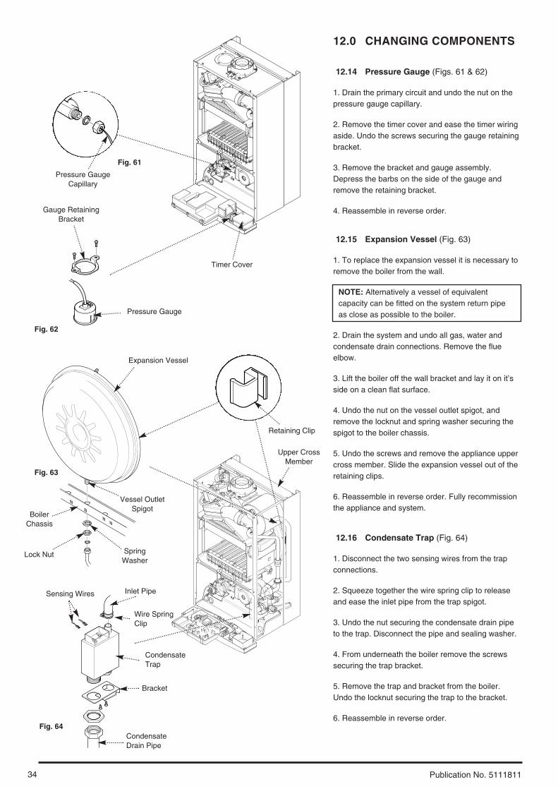
12.14 Pressure Gauge (Figs. 61 & 62)
1. Drain the primary circuit and undo the nut on thepressure gauge capillary.
2. Remove the timer cover and ease the timer wiringaside. Undo the screws securing the gauge retainingbracket.
3. Remove the bracket and gauge assembly.Depress the barbs on the side of the gauge andremove the retaining bracket.
4. Reassemble in reverse order.
12.15 Expansion Vessel (Fig. 63)
1. To replace the expansion vessel it is necessary toremove the boiler from the wall.
NOTE: Alternatively a vessel of equivalentcapacity can be fitted on the system return pipeas close as possible to the boiler.
2. Drain the system and undo all gas, water andcondensate drain connections. Remove the flueelbow.
3. Lift the boiler off the wall bracket and lay it on it’sside on a clean flat surface.
4. Undo the nut on the vessel outlet spigot, andremove the locknut and spring washer securing thespigot to the boiler chassis.
5. Undo the screws and remove the appliance uppercross member. Slide the expansion vessel out of theretaining clips.
6. Reassemble in reverse order. Fully recommissionthe appliance and system.
12.16 Condensate Trap (Fig. 64)
1. Disconnect the two sensing wires from the trapconnections.
2. Squeeze together the wire spring clip to releaseand ease the inlet pipe from the trap spigot.
3. Undo the nut securing the condensate drain pipeto the trap. Disconnect the pipe and sealing washer.
4. From underneath the boiler remove the screwssecuring the trap bracket.
5. Remove the trap and bracket from the boiler.Undo the locknut securing the trap to the bracket.
6. Reassemble in reverse order.
Pressure Gauge
Timer Cover
Pressure GaugeCapillary
Gauge RetainingBracket
Expansion Vessel
Retaining Clip
Vessel OutletSpigot
BoilerChassis
Lock Nut SpringWasher
Fig. 61
Fig. 62
Fig. 63
Fig. 64
Upper CrossMember
Inlet PipeSensing Wires
CondensateTrap
Wire SpringClip
Bracket
CondensateDrain Pipe
35
12.0 CHANGING COMPONENTS
Publication No. 5111811
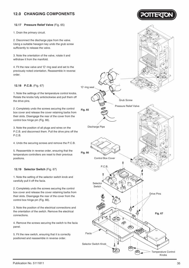
12.17 Pressure Relief Valve (Fig. 65)
1. Drain the primary circuit.
2. Disconnect the discharge pipe from the valve.Using a suitable hexagon key undo the grub screwsufficiently to release the valve.
3. Note the orientation of the valve, rotate it andwithdraw it from the manifold.
4. Fit the new valve and ‘O’ ring seal and set to thepreviously noted orientation. Reassemble in reverseorder.
12.18 P.C.B. (Fig. 67)
1. Note the settings of the temperature control knobs.Rotate the knobs fully anticlockwise and pull them offthe drive pins.
2. Completely undo the screws securing the controlbox cover and release the cover retaining barbs fromtheir slots. Disengage the rear of the cover from thecontrol box hinge pin (Fig. 66).
3. Note the position of all plugs and wires on theP.C.B. and disconnect them. Pull the drive pins off theP.C.B.
4. Undo the securing screws and remove the P.C.B.
5. Reassemble in reverse order, ensuring that thetemperature controllers are reset to their previouspositions.
12.19 Selector Switch (Fig. 67)
1. Note the setting of the selector switch knob andcarefully pull it off the facia.
2. Completely undo the screws securing the controlbox cover and release the cover retaining barbs fromtheir slots. Disengage the rear of the cover from thecontrol box hinge pin (Fig. 66).
3. Note the position of the electrical connections andthe orientation of the switch. Remove the electricalconnections.
4. Remove the screws securing the switch to the faciapanel.
5. Fit the new switch, ensuring that it is correctlypositioned and reassemble in reverse order.
Pressure Relief Valve
Grub Screw
‘O’ ring seal
Discharge Pipe
Control Box Cover
P.C.B.
SelectorSwitch
Facia
Selector Switch Knob
Temperature ControlKnobs
Fig. 65
Fig. 66
Fig. 67
Drive Pins
12.0 CHANGING COMPONENTS
36 Publication No. 5111811
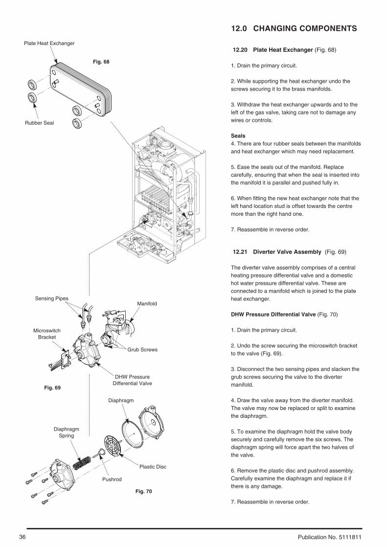
12.20 Plate Heat Exchanger (Fig. 68)
1. Drain the primary circuit.
2. While supporting the heat exchanger undo thescrews securing it to the brass manifolds.
3. Withdraw the heat exchanger upwards and to theleft of the gas valve, taking care not to damage anywires or controls.
Seals4. There are four rubber seals between the manifoldsand heat exchanger which may need replacement.
5. Ease the seals out of the manifold. Replacecarefully, ensuring that when the seal is inserted intothe manifold it is parallel and pushed fully in.
6. When fitting the new heat exchanger note that theleft hand location stud is offset towards the centremore than the right hand one.
7. Reassemble in reverse order.
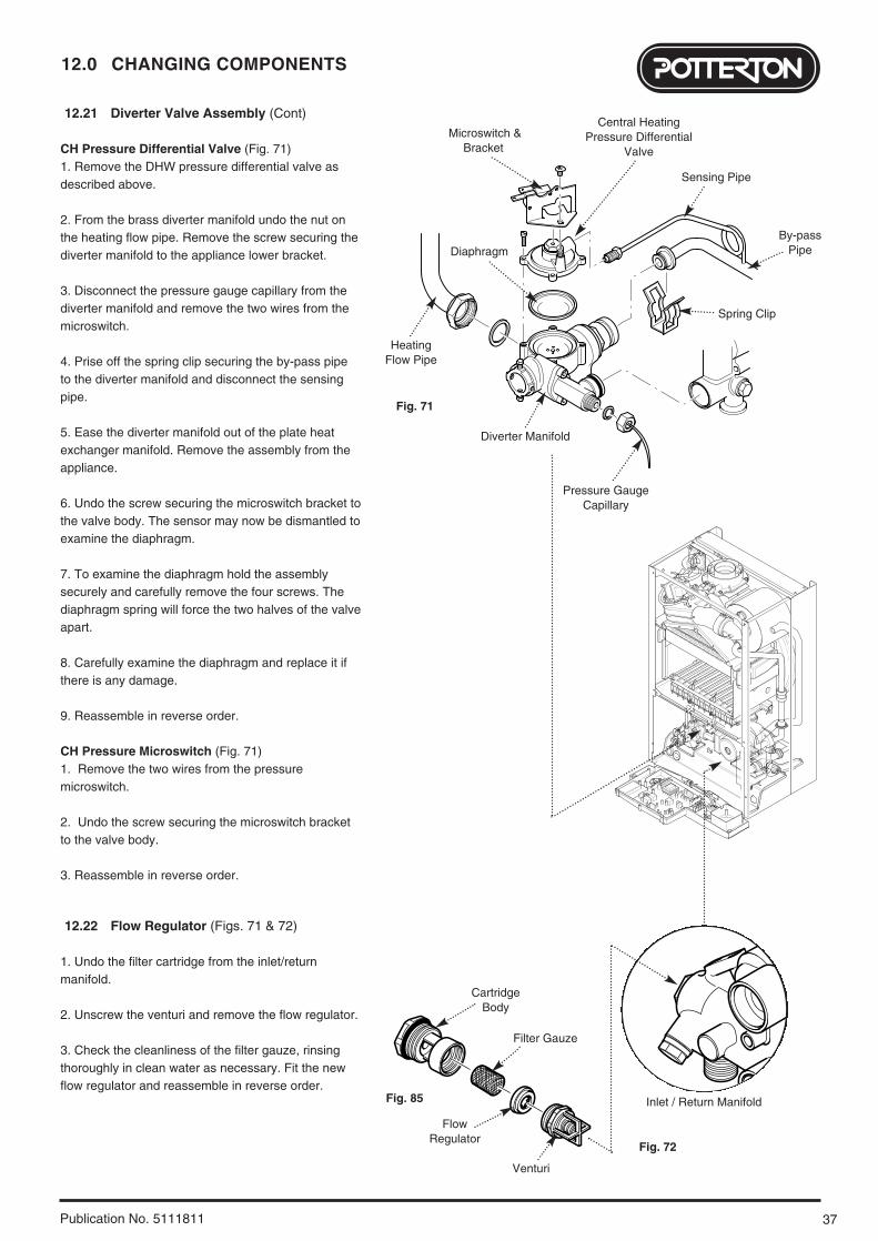
12.21 Diverter Valve Assembly (Fig. 69)
The diverter valve assembly comprises of a centralheating pressure differential valve and a domestichot water pressure differential valve. These areconnected to a manifold which is joined to the plateheat exchanger.
DHW Pressure Differential Valve (Fig. 70)
1. Drain the primary circuit.
2. Undo the screw securing the microswitch bracketto the valve (Fig. 69).
3. Disconnect the two sensing pipes and slacken thegrub screws securing the valve to the divertermanifold.
4. Draw the valve away from the diverter manifold.The valve may now be replaced or split to examinethe diaphragm.
5. To examine the diaphragm hold the valve bodysecurely and carefully remove the six screws. Thediaphragm spring will force apart the two halves ofthe valve.
6. Remove the plastic disc and pushrod assembly.Carefully examine the diaphragm and replace it ifthere is any damage.
7. Reassemble in reverse order.
Plate Heat Exchanger
Rubber Seal
DHW Pressure Differential Valve
MicroswitchBracket
Grub Screws
ManifoldSensing Pipes
Plastic Disc
Pushrod
DiaphragmSpring
Diaphragm
Fig. 68
Fig. 69
Fig. 70
37
12.0 CHANGING COMPONENTS
Publication No. 5111811
12.21 Diverter Valve Assembly (Cont)
CH Pressure Differential Valve (Fig. 71)1. Remove the DHW pressure differential valve asdescribed above.
2. From the brass diverter manifold undo the nut onthe heating flow pipe. Remove the screw securing thediverter manifold to the appliance lower bracket.
3. Disconnect the pressure gauge capillary from thediverter manifold and remove the two wires from themicroswitch.
4. Prise off the spring clip securing the by-pass pipeto the diverter manifold and disconnect the sensingpipe.
5. Ease the diverter manifold out of the plate heatexchanger manifold. Remove the assembly from theappliance.
6. Undo the screw securing the microswitch bracket tothe valve body. The sensor may now be dismantled toexamine the diaphragm.
7. To examine the diaphragm hold the assemblysecurely and carefully remove the four screws. Thediaphragm spring will force the two halves of the valveapart.
8. Carefully examine the diaphragm and replace it ifthere is any damage.
9. Reassemble in reverse order.
CH Pressure Microswitch (Fig. 71)1. Remove the two wires from the pressuremicroswitch.
2. Undo the screw securing the microswitch bracketto the valve body.
3. Reassemble in reverse order.
12.22 Flow Regulator (Figs. 71 & 72)
1. Undo the filter cartridge from the inlet/returnmanifold.
2. Unscrew the venturi and remove the flow regulator.
3. Check the cleanliness of the filter gauze, rinsingthoroughly in clean water as necessary. Fit the newflow regulator and reassemble in reverse order.
Pressure GaugeCapillary
HeatingFlow Pipe
Spring Clip
By-passPipe
Sensing Pipe
Diaphragm
Diverter Manifold
Microswitch &Bracket
Fig. 71
Inlet / Return Manifold
CartridgeBody
Filter Gauze
FlowRegulator
Venturi
Fig. 85
Fig. 72
Central HeatingPressure Differential
Valve

12.0 CHANGING COMPONENTS
38 Publication No. 5111811
12.23 Secondary Heat Exchanger (Fig. 73)
1. Drain the primary circuit
2. Undo the four screws securing the right handcase panel. Remove the panel.
3. Prise the connecting clips from the heatexchanger return pipe and the boiler return pipe.Remove the pipes.
4. Slacken the screws on the fan spigot outletpipe clamp. Ease the clamp to the left. Undo thescrew at the left hand end of the pipe.
5. Remove the nut securing the elbow to thesecondary heat exchanger. Draw the elbow andoutlet pipe forwards.
6. Remove the secondary heat exchanger fromthe outer drum by easing it forward.
7. Reassemble in reverse order of dismantling.
12.24 Flue Overheat Thermostat (Fig. 74)
NOTE: The flue overheat thermostat includesa reset button. Check that the thermostat willnot reset before replacing.
1. Remove the fan spigot outlet pipe from the fanand elbow.
2. Pull the two wires off the terminals on the flueoverheat thermostat. Unscrew the thermostatfrom the adaptor in the outlet elbow.
3. Reassemble in reverse order of dismantling.
Ease Fan Spigot OutletPipe Clamp Inwards
Overheat Thermostat
Fan Spigot OutletPipe Clamp
Fan SpigotOutlet Pipe
SecondaryHeat Exchanger
Outer Drum
Boiler Return Pipe
Pipe Connecting Clip
ElbowHeat ExchangerReturn Pipe
Fig. 73
Fig. 74
Fan Spigot Outlet Pipe
39
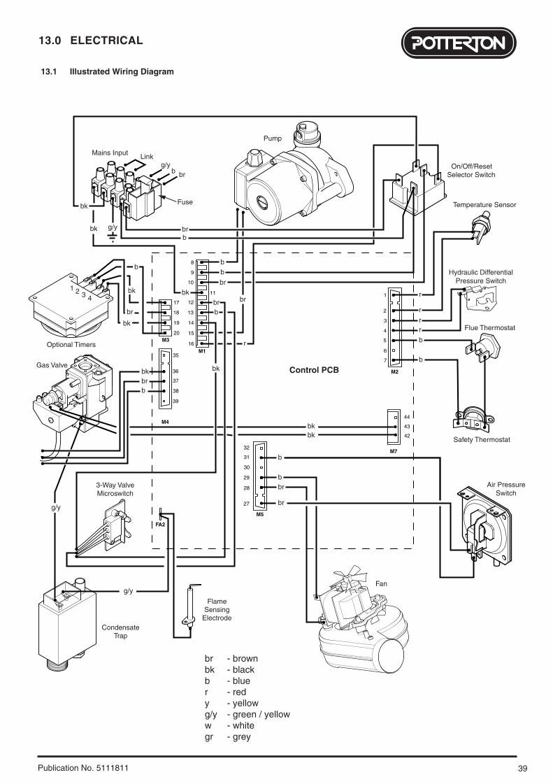
13.0 ELECTRICAL
Publication No. 5111811
Optional Timers
Pump
Gas Valve
Air PressureSwitch
Safety Thermostat
Pressure SwitchHydraulic Differential
Temperature Sensor
Selector SwitchOn/Off/Reset
Fan
Control PCB
Flame
ElectrodeSensing
Microswitch3-Way Valve
M2
M5
M4
M1
M3
FA2
15
16
14
13
12
20
19
18
17
11
10
39
38
37
36
35
9
7
6
5
4
3
2
1
8
Mains Input
Fuse
Link
g/y
g/yb br
b
bb
b
br
br
br br
r
bk
bk
br
brb
r
r
rr
b
b
b
brb
1
bk
bk
bk
b
bk
bk
br
2 3 4
Flue Thermostat
CondensateTrap
g/y
g/y
M7
bkbk
28
29
30
31
32
27
42
43
44
br - brownbk - blackb - bluer - redy - yellowg/y - green / yelloww - whitegr - grey
13.1 Illustrated Wiring Diagram
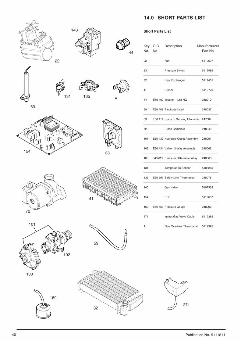
14.0 SHORT PARTS LIST
40 Publication No. 5111811
Short Parts List
Key G.C. Description ManufacturersNo. No. Part No.
22 Fan 5112627
23 Pressure Switch 5112999
32 Heat Exchanger 5112431
41 Burner 5112770
44 E66 402 Injector - 1.18 NG 248210
59 E66 408 Electrode Lead 248037
63 E66 411 Spark or Sensing Electrode 247384
72 Pump Complete 248042
101 E66 432 Hydraulic Outlet Assembly 248061
102 E66 434 Valve - 3-Way Assembly 248062
103 343 619 Pressure Differential Assy 248063
131 Temperature Sensor 5108265
135 E66 697 Safety Limit Thermostat 248078
140 Gas Valve 5107339
154 PCB 5112657
169 E66 453 Pressure Gauge 248090
371 Igniter/Gas Valve Cable 5112385
A Flue Overheat Thermostat 5112395
22
140
44
63
154
72
135
59
41
101
102
103
32
169
131
23
A
371
41
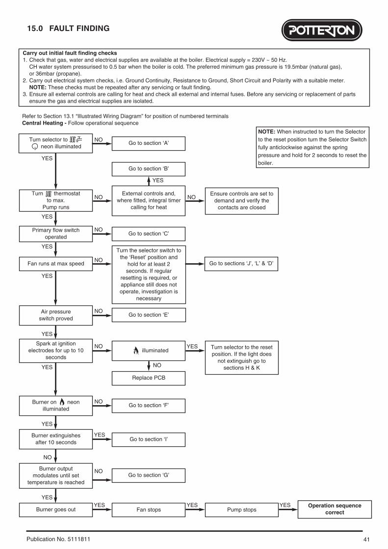
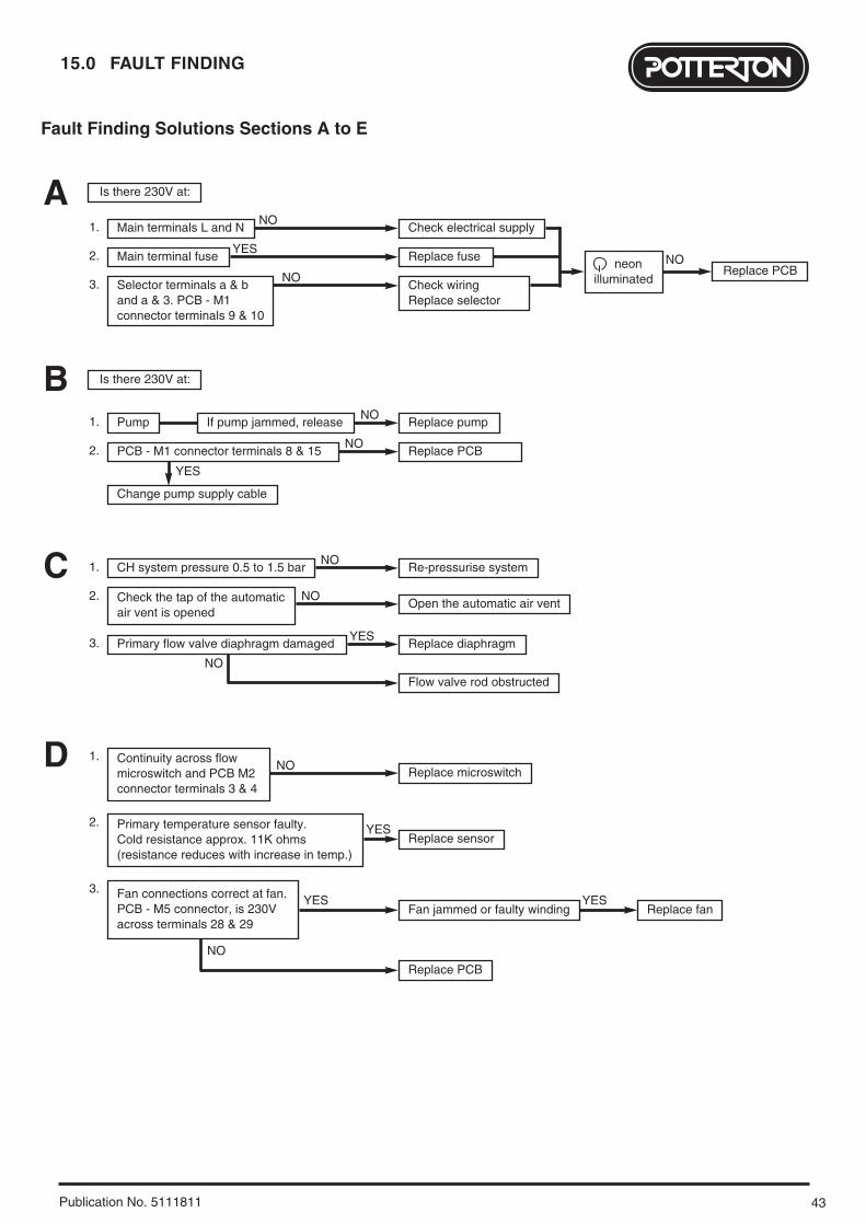
15.0 FAULT FINDING
Publication No. 5111811
Carry out initial fault finding checks1. Check that gas, water and electrical supplies are available at the boiler. Electrical supply = 230V ~ 50 Hz.
CH water system pressurised to 0.5 bar when the boiler is cold. The preferred minimum gas pressure is 19.5mbar (natural gas), or 36mbar (propane).
2. Carry out electrical system checks, i.e. Ground Continuity, Resistance to Ground, Short Circuit and Polarity with a suitable meter. NOTE: These checks must be repeated after any servicing or fault finding.
3. Ensure all external controls are calling for heat and check all external and internal fuses. Before any servicing or replacement of parts ensure the gas and electrical supplies are isolated.
Refer to Section 13.1 “Illustrated Wiring Diagram” for position of numbered terminalsCentral Heating - Follow operational sequence
Turn selector to neon illuminated
Primary flow switchoperated
Fan runs at max speed
Burner goes out
Turn thermostat to max.
Pump runs
Air pressure switch proved
illuminated
Burner on neonilluminated
Burner output modulates until set
temperature is reached
Spark at ignitionelectrodes for up to 10
seconds
Go to section ‘A’
Go to section ‘B’
Go to section ‘C’
Go to sections ‘J’, ‘L’ & ‘D’
Go to section ‘E’
Replace PCB
Turn selector to the resetposition. If the light does
not extinguish go tosections H & K
Go to section ‘F’
Go to section ‘I’
Go to section ‘G’
Fan stops Pump stopsOperation sequence
correct
Turn the selector switch tothe ‘Reset’ position and
hold for at least 2seconds. If regular
resetting is required, orappliance still does notoperate, investigation is
necessary
External controls and,where fitted, integral timer
calling for heat
Ensure controls are set todemand and verify the
contacts are closed
Burner extinguishes after 10 seconds
YES
YES
YES
YES
YES
YES
YES
YES
YES
NO
YESYES YES YES
NO
NO NO
NO
NO
NO
NO
NO
NO
YES
NO
NOTE: When instructed to turn the Selectorto the reset position turn the Selector Switchfully anticlockwise against the springpressure and hold for 2 seconds to reset theboiler.

15.0 FAULT FINDING
42 Publication No. 5111811
Domestic Hot Water - Follow operational sequence
Turn selector to neon illuminated
Primary flow switchoperated
Fan runs at max speed
Pump runs
Turn thermostat tomax. Open DHW tap fully.DHW flow switch operated
Primary water is divertedfrom CH system to DHWheat exchanger and flow
microswitch operated
Continuity across DHWflow microswitch terminalsand PCB - M1 connector
terminals 13 & 14(terminals 12-14 open)
Air pressure switchproved
neon illuminated
Burner on neonilluminated
Spark at ignitionelectrodes for up to 10
seconds
Go to section ‘A’
Go to section ‘B’
Go to section ‘C’
Go to section ‘J’, ‘L’ & ‘D’
Replace PCB
Turn the selector to thereset position. If the lightdoes not extinguish go to
section H & K
Go to section ‘F’
Go to section ‘I’
DHW flow valve senses no flow.
Primary water diverted toCH system. DHW flow
switch released off
Close DHW tap
Burner goes out
Diverter valve spindleassembly faulty
Pump stopsOperation sequence
correct
Turn the selector switch tothe ‘Reset’ position and
hold for at least 2seconds. If regular
resetting is required, orappliance still does notoperate investigation is
necessary
Go to section ‘E’
Burner extinguishes after 10 seconds
YES
YES
YES
YES
YES
YES
YES
YES
YES
YES
YES
YES
YES
YES
YES
YES
NO
Fan stopsNO YES YES
YES
NO
NO
DHW flow rate more than2.5l/min.
Is mains water filter and differential
assembly clean?
DHW flow valvediaphragm damaged
DHW flow valve rodobstructed
Replace DHW flowmicroswitch
Replace PCB
Replace diaphragm
NO
NO
NO
YES
NO
NO
NO
NO
NO
NO
NO
NOReduce the DHW flowrate. If burner does not
modulate cleantemperature sensor andDHW heat exchanger. If
modulation does not occurgo to section ‘G’
Burner output modulatesto maintain temperature
set at thermostat
NO
43
15.0 FAULT FINDING
Publication No. 5111811
Fault Finding Solutions Sections A to E
Is there 230V at:
Is there 230V at:
Main terminals L and N Check electrical supply1. NO
Main terminal fuse Replace fuseReplace PCBneon
illuminated
2. YES
Selector terminals a & band a & 3. PCB - M1connector terminals 9 & 10
Check wiringReplace selector
3. NO
NO
A
Pump Replace pump1. NO
PCB - M1 connector terminals 8 & 15 Replace PCB2. NO
Change pump supply cable
YES
B
CH system pressure 0.5 to 1.5 bar Re-pressurise system1. NO
Primary flow valve diaphragm damaged Replace diaphragm
Flow valve rod obstructed
3. YES
Check the tap of the automaticair vent is opened
Open the automatic air vent2. NO
NO
C
YES
Continuity across flowmicroswitch and PCB M2connector terminals 3 & 4
Replace microswitch1.
NO
NO
Primary temperature sensor faulty. Cold resistance approx. 11K ohms (resistance reduces with increase in temp.)
Replace sensor2.
YESFan connections correct at fan.PCB - M5 connector, is 230Vacross terminals 28 & 29
Fan jammed or faulty winding
Replace PCB
Replace fanYES
3.
D
If pump jammed, release
15.0 FAULT FINDING
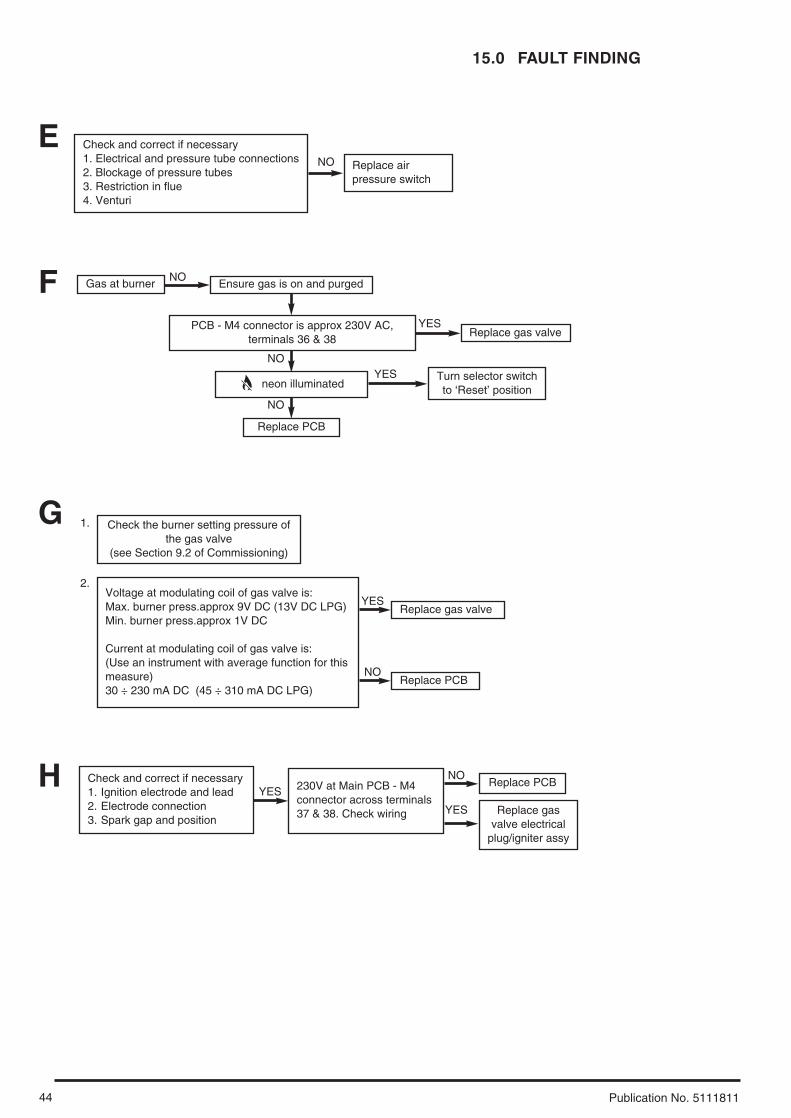
44 Publication No. 5111811
Check and correct if necessary1. Electrical and pressure tube connections2. Blockage of pressure tubes3. Restriction in flue4. Venturi
NO
EReplace airpressure switch
Gas at burner Ensure gas is on and purged
Replace PCB
Replace gas valve
neon illuminated
PCB - M4 connector is approx 230V AC,terminals 36 & 38
YES
Turn selector switchto ‘Reset’ position
YES
NO
NO
NO
F
Replace PCB
G
Check and correct if necessary1. Ignition electrode and lead2. Electrode connection3. Spark gap and position
230V at Main PCB - M4connector across terminals 37 & 38. Check wiring
YESNO
Replace gasvalve electrical
plug/igniter assy
YES
H
YES
Check the burner setting pressure ofthe gas valve
(see Section 9.2 of Commissioning)
1.
Replace gas valve
NOReplace PCB
2.Voltage at modulating coil of gas valve is:Max. burner press.approx 9V DC (13V DC LPG)Min. burner press.approx 1V DC
Current at modulating coil of gas valve is:(Use an instrument with average function for thismeasure)30 ÷ 230 mA DC (45 ÷ 310 mA DC LPG)
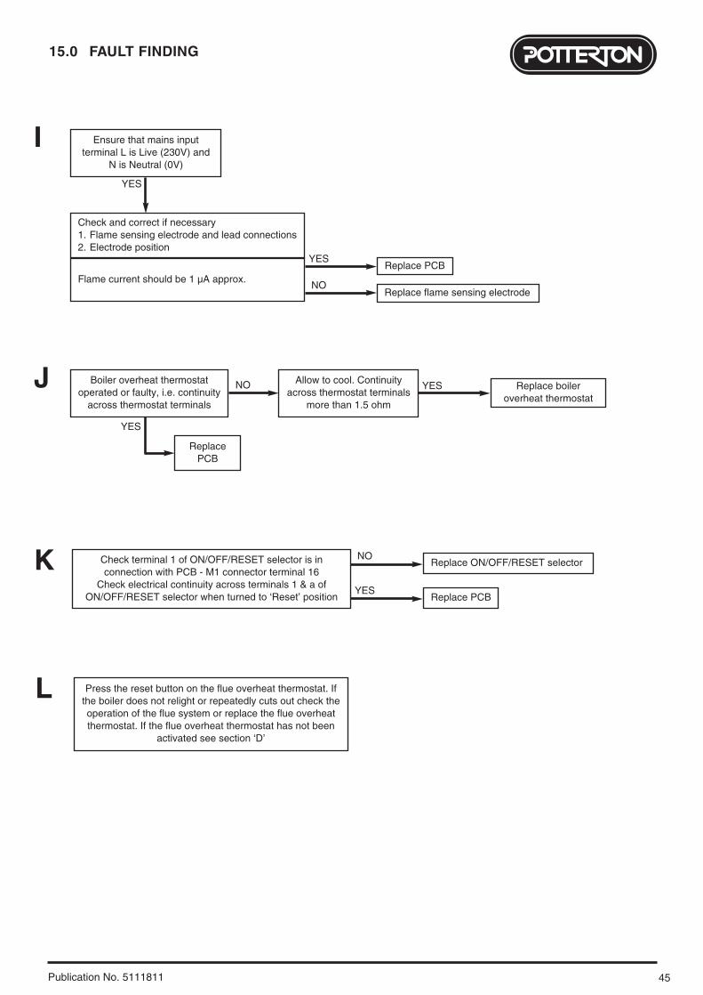
45
15.0 FAULT FINDING
Publication No. 5111811
Check and correct if necessary1. Flame sensing electrode and lead connections2. Electrode position
Flame current should be 1 µA approx.Replace PCB
ReplacePCB
YES
YES
Replace flame sensing electrodeNO
YES
Ensure that mains inputterminal L is Live (230V) and
N is Neutral (0V)
I
Check terminal 1 of ON/OFF/RESET selector is inconnection with PCB - M1 connector terminal 16
Check electrical continuity across terminals 1 & a ofON/OFF/RESET selector when turned to ‘Reset’ position
Replace ON/OFF/RESET selectorNO
Replace PCBYES
K
Replace boileroverheat thermostat
YESNOBoiler overheat thermostatoperated or faulty, i.e. continuity
across thermostat terminals
Allow to cool. Continuityacross thermostat terminals
more than 1.5 ohm
J
L Press the reset button on the flue overheat thermostat. Ifthe boiler does not relight or repeatedly cuts out check theoperation of the flue system or replace the flue overheatthermostat. If the flue overheat thermostat has not been
activated see section ‘D’

16.0 NOTES
46 Publication No. 5111811

47Publication No. 5111811
Publication No. 5111811 - Iss. 1 (06/2004)
All descriptions and illustrations provided in this leaflet have been
carefully prepared but we reserve the right to make changes and
improvements in our products which may affect the accuracy of the
information contained in this leaflet. All goods are sold subject to
our standard Conditions of Sale which are available on request.
General Enquiries (GB)
Tel. 08706 060 780Technical (GB)
Tel. 08706 049 049Service (GB)
Tel. 08706 096 096Fax. 01926 410 006
Literature Request (GB)
Tel. 08706 060 623
Technical (IE)
Tel. 1850 560570
BAXI POTTERTONA Trading Division of Baxi Heating UK LtdBrownedge Road Bamber Bridge Preston Lancashire PR5 6SNAfter Sales Service 08706 096 096 Technical Enquiries 08706 049 049Website www.potterton.co.uk
company923.634.2