Embed Size (px)
Citation preview

© Baxi Heating UK Ltd 2012
Installation & Service Instructions System EcoRange
These instructions include the Benchmark Commissioning Checklistand should be left with the user for safe keeping.

2 © Baxi Heating UK Ltd 2012
Natural Gas
Main System 24 Eco G.C.No 41 467 11Main System 28 Eco G.C.No 41 467 12
© Baxi Heating UK Ltd 2012 All rights reserved. No part of this publication maybe reproduced or transmitted in any form or by any means, or stored in anyretrieval system of any nature (including in any database), in each case whetherelectronic, mechanical, recording or otherwise, without the prior writtenpermission of the copyright owner, except for permitted fair dealing underCopyrights, Designs and Patents Act 1988.
Applications for the copyright owner’s permission to reproduce or make otheruse of any part of this publication should be made, giving details of the proposeduse, to the following address:
The Company Secretary, Baxi Heating UK Limited,Brooks House, Coventry Road, Warwick. CV34 4LL
Full acknowledgement of author and source must be given.
WARNING: Any person who does any unauthorised act in relation to acopyright work may be liable to criminal prosecution and civil claims for damages.
The Benchmark Scheme
Benchmark places responsibilities on both manufacturers and installers. Thepurpose is to ensure that customers are provided with the correct equipment fortheir needs, that it is installed, commissioned and serviced in accordance with themanufacturer’s instructions by competent persons and that it meets therequirements of the appropriate Building Regulations. The Benchmark Checklistcan be used to demonstrate compliance with Building Regulations and should beprovided to the customer for future reference.
Installers are required to carry out installation, commissioning and servicing workin accordance with the Benchmark Code of Practice which is available from theHeating and Hotwater Industry Council who manage and promote the Scheme.Visit www.centralheating.co.uk for more information.
0086ISO 9001FM 00866
Building Regulations and the Benchmark CommissioningChecklist
Building Regulations (England & Wales) require notification ofthe installation of a heating appliance to the relevant LocalAuthority Building Control Department. From 1 April 2005 thiscan be achieved via a Competent Persons Self CertificationScheme as an option to notifying the Local Authority directly.Similar arrangements will follow for Scotland and will apply inNorthern Ireland from 1 January 2006.
The Health & Safety Executive operates the ‘Gas Safe Register’,a self-certification scheme for gas heating appliances.
These arrangements represent a change from the situationwhereby compliance with Building Regulations was accepted asbeing demonstrated by completion of the Benchmark Logbook(which was then left on site with the customer).
With the introduction of Self Certification Schemes, theBenchmark Logbook is being withdrawn. However, a similardocument in the form of a commissioning checklist and serviceinterval record is incorporated at the back of these instructions.
This company is a member of the Benchmark initiative and fullysupports the aims of the programme. Its aim is to improve thestandards of installation and commissioning of central heatingsystems in the UK and to encourage the regular servicing of allcentral heating systems to ensure safety and efficiency.
Building Regulations require that installations should complywith manufacturer's instructions. It is therefore important thatthe commissioning checklist is completed by the installer. Therelevant section of Building Regulations only relates todwellings. Therefore the checklist only applies if the appliance isbeing installed in a dwelling or some related structure.
The flowchart opposite gives guidance for installers on theprocess necessary to ensure compliance with BuildingRegulations.

3
Installer Notification Guidelines
© Baxi Heating UK Ltd 2012
Choose BuildingRegulations Notification
Route
Contact your relevant LocalAuthority Building Control(LABC) who will arrangean inspection or contacta government approved
inspector
LABC will record the dataand will issue a
certificate of compliance
‘Gas Safe Register’ will issue aBuilding Regulations ComplianceCertificate to the property ownerand inform the relevant LABC
You must ensure that thecertificate number issued by
the ‘Gas Safe Register’ is written onto the Benchmark Checklist
Scheme Members only
Call ‘Gas Safe Register’ on: 0800 408 5577
or log onto:www.gassaferegister.co.uk
within 10 days
If you notify via the ‘Gas Safe Register’, the register will issue
the Building Regulationscertificate on members’ behalf
Complete theBenchmark Checklist
Install and Commission thisappliance to manufacturer's
instructions
Competent Person'sSelf Certification Scheme
Building Control
Complete theBenchmark Checklist
Install and Commission thisappliance to manufacturer's
instructions

4
Legislation
© Baxi Heating UK Ltd 2012
Codes of Practice - refer to the most recent version
This company declare that no substances harmful to healthare contained in the appliance or used during appliancemanufacture.
The appliance is suitable only for installation in GB and IE andshould be installed in accordance with the rules in force, andonly used in a suitably ventilated location.
In GB, the installation must be carried out by a CORGIRegistered Installer. It must be carried out in accordance withthe relevant requirements of the:• Gas Safety (Installation & Use) Regulations.• The appropriate Building Regulations either The Building
Regulations, The Building Regulations (Scotland), Building Regulations (Northern Ireland).
• The Water Fittings Regulations or Water Byelaws in Scotland.
• The Current I.E.E. Wiring Regulations.
Where no specific instructions are given, reference should bemade to the relevant British Standard Code of Practice.
In IE, the installation must be carried out by a competentPerson and installed in accordance with the current edition ofI.S. 813 ‘Domestic Gas Installations’, the current BuildingRegulations and reference should be made to the current ETCIrules for electrical installation.
All systems must be thoroughly flushed and treated withinhibitor (see section 6.2).
The boiler meets the requirements of Statutory Instrument “ The Boiler (Efficiency)Regulations 1993 No 3083” and is deemed to meet the requirements of Directive92/42/EEC on the energy efficiency requirements for new hot water boilers fired withliquid or gaseous fuels:-
Type test for purpose of Regulation 5 certified by: Notified Body 0087.
Product/Production certified by:Notified Body 0086.
For GB/IE only.
IMPORTANT - Installation, Commissioning, Service & Repair
This appliance must be installed in accordance with the manufacturer’s instructions andthe regulations in force. Read the instructions fully before installing or using theappliance.
In GB, this must be carried out by a competent person as stated in the Gas Safety(Installation & Use) Regulations.
Definition of competence: A person who works for a Gas Safe registered companyand holding current certificates in the relevant ACS modules, is deemed competent.
In IE, this must be carried out by a competent person as stated in I.S. 813 “DomesticGas Installations”.
The addition of anything that may interfere with the normal operation of the appliancewithout express written permission from the manufacturer or his agent could invalidatethe appliance warranty. In GB this could also infringe the Gas Safety (Installation andUse) Regulations.
Warning - Check the information on the data plate is compatible with local supplyconditions.
All Gas Safe registered engineers carry an ID card with their licence number and aphotograph. You can check your engineer is registered by telephoning 0800 408 5500 or online at www.gassaferegister.co.uk
In GB the following Codes of Practice apply:Standard ScopeBS 6891 Gas Installation.BS 5546 Installation of hot water supplies for domestic
purposes.BS EN 12828 Heating systems in buildings.BS EN 14336 Installation & commissioning of water based
heating systems.BS 6798 Installation of gas fired hot water boilers.BS 5440 Part 1 Flues.BS 5440 Part 2 Ventilation.BS 7074 Expansion vessels and ancillary equipment for
sealed water systems.BS 7593 Treatment of water in domestic hot water
central heating systems.
In IE the following Codes of Practice apply:Standard ScopeI.S. 813 Domestic Gas Installations.The following standards give valuable additional information;BS 5546 Installation of hot water supplies for domestic
purposes.BS EN 12828 Heating systems in buildings.BS EN 14336 Installation & commissioning of water based
heating systems.BS 7074 Expansion vessels and ancillary equipment for
sealed water systems.BS 7593 Treatment of water in domestic hot water
central heating systems.
5
Safe Manual Handling
© Baxi Heating UK Ltd 2012
General
The following advice should be adhered to, from when first handling the boiler to the final stages of installation, and also during maintenance.
Most injuries as a result of inappropriate handling and lifting are to the back, but all other parts of the body are vulnerable, particularly shoulders, arms and hands.Health & Safety is the responsibility of EVERYONE.
There is no ‘safe’ limit for one man - each person has different capabilities. The boiler should be handled and lifted by TWO PEOPLE.
Do not handle or lift unless you feel physically able.
Wear appropriate Personal Protection Equipment e.g. protective gloves, safety footwear etc.
Preparation
Co-ordinate movements - know where, and when, you are both going.
Minimise the number of times needed to move the boiler - plan ahead.
Always ensure when handling or lifting the route is clear and unobstructed. If possible avoid steps, wet or slippery surfaces, unlit areas etc. and take special careon ladders/into lofts.
Technique
When handling or lifting always use safe techniques - keep your back straight, bend your knees. Don’t twist - move your feet, avoid bending forwards andsideways and keep the load as close to your body as possible.
Where possible transport the boiler using a sack truck or other suitable trolley.
Always grip the boiler firmly, and before lifting feel where the weight is concentrated to establish the centre of gravity, repositioning yourself as necessary. See the‘Installation’ section of these instructions for recommended lift points.
Remember
The circumstances of each installation are different. Always asses the risks associated with handling and lifting according to the individual conditions.
If at any time when installing the boiler you feel that you may have injured yourself STOP !! DO NOT ‘work through’ the pain - you may cause further injury.
IF IN ANY DOUBT DO NOT HANDLE OR LIFT THE BOILER - OBTAIN ADVICE OR ASSISTANCE BEFORE PROCEEDING !!

6 © Baxi Heating UK Ltd 2012
CONTENTS
1.0 Introduction 7
2.0 General Layout 8
3.0 Appliance Operation 9
4.0 Technical Data 10
5.0 Dimensions and Fixings 11
6.0 System Details 12
7.0 Site Requirements 14
8.0 Flue Options 20
9.0 Plume Displacement 25
10.0 Installation 29
11.0 Commissioning 33
12.0 Completion 35
13.0 Servicing 36
14.0 Changing Components 38
15.0 Setting the Gas Valve 46
16.0 Electrical 47
17.0 Short Parts List 48
18.0 Fault Finding 49
Benchmark Checklist 54
Section Page

7
1.0 Introduction
© Baxi Heating UK Ltd 2012
1.1 Description
1. The Main System Eco is a fully automatic gas fired wallmounted condensing system boiler. It is room sealed and fanassisted.
2. The boiler is set to give a maximum output of :-
24 models - 25.94 kW26.95 kW (Condensing)
28 models - 28.63 kW30.20 kW (Condensing)
3. It is designed for use on Natural Gas (G20).
4. The boiler incorporates a circulating pump and expansionvessel. It is suitable for use only on fully pumped sealedsystems.
5. The boiler data badge gives details of the model, serialnumber and Gas Council number and is situated on the frontsloping face of the hydraulic plate. It is visible when the casefront panel is removed and the control box hinged down (Fig. 1 & 1a).
6. The boiler model name and serial number are also shownon the information label on the back of the facia door. This isfor user reference.
7. The boiler is intended to be installed in residential /commercial / light industrial E.M.C. environments on agoverned meter supply only.
8. The boiler must be installed with one of the purposedesigned flues such as the standard horizontal flue kit, part no.5118489 .
9. All systems must be thoroughly flushed and treated withinhibitor (see section 6.1).
1.2 Contents of Pack
1. Boiler Unit2. Wall Plate (inc. taps)3. Set of Pipes (inc. nuts)4. Template & ‘Quick Fit’ Guide5. Literature Pack
Fig. 1
Control Box
Case Front Panel
Information Label
Data Badge
Fig. 1a
Facia Door
8
2.0 General Layout
© Baxi Heating UK Ltd 2012
2.1 Layout
1. Expansion Vessel
2. Automatic Air Vent
3. Primary Return Temperature Sensor
4. Circulation Pump
5. Drain Off Point
6. Pressure Relief Valve
7. Selector Switch
8. Central Heating System Pressure Gauge
9. PCB
10. Control Box
11. Gas Valve
12. Condensate Trap
13. Heat Exchanger Air Vent
14. Electrode Assembly
15. Primary Heat Exchanger
16. Fan Assembly
17. On/Off/Reset Selector Switch
18. Central Heating Temperature Control
19. Calibration Control
20. Water Pressure Sensor
21. Gas/Air Inlet
22. Burner Mounting Panel
23. Igniter
24. Burner On Light
25. Central Heating Mode Light
26. Calibration Mode Light
27. Display
13
17 18 19 8
Reset
bar
0
1
2
3
4
2
3
4
5
6
7
89
10
11
12
1
14
16
24
25 26
27
21
23
22
15
20
9
3.0 Appliance Operation
© Baxi Heating UK Ltd 2012
1
2
4
5
6
7
8
19
18
9
10 12 11
14
13
15
16
17
3
Key
1 Heat Exchanger2 Burner 3 Ignition Electrode4 Flame Sensing Electrode5 Gas Valve6 Pump7 Automatic Air Vent8 Pressure Relief Valve9 Boiler Drain Point10 Gas Inlet11 Boiler Flow12 Boiler Return13 Pressure Gauge14 Automatic By-Pass15 Water Pressure Sensor16 Safety Thermostat17 Temperature Sensor18 Expansion Vessel19 Return Temperature Sensor20 Fan
Boiler Primary Circuit
Fig. 2
20
3.1 Operating Mode (Fig. 2)
1. With a demand for heating or hot water, the pumpcirculates water through the primary circuit. If the pressure isat least 0.5 bar and the ignition sequence will start.
2. When the flow temperature exceeds the settingtemperature, a 3 minute delay occurs before the burnerrelights automatically (anti-cycling). The pump continues torun during this period.
3. When the demand is satisfied the burner is extinguishedand the pump continues to run for a period of 3 minutes(Pump Overrun).
IMPORTANT: When the selector switch is in the ‘0’(Off) position the electrical supply to the boiler isisolated. The boiler will not operate.
3.2 Frost Protection Mode
1. The frost protection mode is integral to the appliance andfunctions when the selector switch (see Section 2.1) is in theON position ( ). If the system temperature falls below5° C then the boiler will fire on its minimum setting until aflow temperature of 30° C is reached. Further protectioncan be incorporated by using a system frost thermostat.
3.3 Pump Protection
1. With the selector switch (see Section 2.1) in the ONposition ( ) the pump will automatically operate for 1minute in every 24 hours to prevent sticking.

10
4.0 Technical Data
© Baxi Heating UK Ltd 2012
4.1 System 24 & 28 Eco
Flue Terminal Diameter 100mmDimensions Projection 125mm
Outercase DimensionsCasing Height - 780mmOverall Height Inc Flue Elbow - 965mmCasing Width - 450mmCasing Depth - 345mm
WeightsPackaged Boiler Carton 51.1 kg (24 &28)Installation Lift Weight 44.5 kg (24 & 28)
Central Heating Primary CircuitPressures
barSafety Discharge 3Max Operating 2.5Min Operating 0.5Recommended Operating Range 1-2
PumpAvailable Head See graph below
Expansion Vessel - (For Central Heating only.Integral with appliance)
barMin Pre-charge Pressure 0.5
(18,24) (27)Max Capacity of litre litre CH System 125 155
Primary Water Contentof Boiler (unpressurised) 2.5 2.8
Connections copper tailsGas Supply - 22mmCentral Heating Flow - 22mmCentral Heating Return - 22mmPressure Relief Discharge - 15mm
TemperaturesC.H. Flow Temp (adjustable)
25°C to 80°C max (± 5°C)
NOx Class 5
0200 400 600 800 1000 1200 1400
0.5
1
1.5
2
2.5
3
3.5
4
Met
re (
wg)
Flow Rate (l/h)
Pump - Available Head (24,27)
0
5
5.5
4.5
ClearancesAbove Casing 200 mm Min
300 mm Min (80/125mm flue)Below Casing 200 mm MinFront 450 mm Min (For Servicing)
Front 5 mm Min (In Operation)
L.H. Side 5 mm MinR.H. Side 5 mm Min (In Operation)
Heat Input CH (Net) Max Min
24 model kW 26.06 7.82
28 model kW 29.32 8.8
Heat Output CH (Non-Condensing)Max Min
24 model kW 25.94 7.61
28 model kW 28.63 8.56
Electrical Supply 230V~ 50Hz (Appliance must be connected to an
earthed supply)
Power Consumption 150W
Electrical Protection IPX0D (with timer)IPX4D (without timer)
Internal Fuse Rating F2L
Appliance Category CAT I 2H
Inlet Pressure (Natural Gas - G20)mbar 20
Injector (Natural Gas - G20)
6.0mm (24 & 28 models)
Appliance Type C13 C33 C53
Heat Output CH (Condensing)Max Min
24 model kW 26.95 8.37
28 model kW 30.20 9.42
Max Gas Rate (Natural Gas - G20)(After 10 mins)
24 model m3/h 2.76
28 model m3/h 3.10
Condensate DrainTo accept 21.5mm (3/4 in) plastic waste pipe
Heat Input CH (Gross) Max Min
24 model kW 28.92 8.68
28 model kW 32.54 9.77
External Fuse Rating 3A
SAP 2005 Seasonal Efficiency for 24 modelsis 91.1%
SAP 2005 Seasonal Efficiency for 28 modelsis 90.2%
This value is used in the UK Government’s Standard
Assessment Procedure (SAP) for energy rating of
dwellings. The test data from which it has been
calculated has been certified by 0087.
SEDBUK Declaration
NOTE: All data in this section are nominal values and subject to normal production tolerances.
11
5.0 Dimensions and Fixings
© Baxi Heating UK Ltd 2012
Tap Rail
360° Orientation
Tube Ø 100mm
DC
B
A
G
F
H
H
HeatingReturn(22mm)
HeatingFlow
(22mm)
Pressure ReliefValve
(15mm)
GasInlet
(22mm)
130 mm 130 mm 65 mm
CondensateDrain
127 mm
Dimensions
A 780mm
B 345mm
C 450mm
D 116mm Ø Min.
F 145mm
G 132mm210mm (80/125)
H 225mm
At Least 1.5o

12
6.0 System Details
© Baxi Heating UK Ltd 2012
6.1 Central Heating Circuit
1. The appliance is suitable for fully pumped SEALED SYSTEMS
ONLY.
Treatment of Water Circulating Systems• All recirculatory water systems will be subject to corrosionunless an appropriate water treatment is applied. This meansthat the efficiency of the system will deteriorate as corrosionsludge accumulates within the system, risking damage topump and valves, boiler noise and circulation problems.
• When fitting new systems flux will be evident within thesystem, which can lead to damage of system components.
• All systems must be thoroughly drained and flushed outusing, for example, Sentinel X300 or X400 or Fernox F3.They should be used following the flushing agentmanufacturer’s instructions.
• System additives - corrosion inhibitors and flushing agents/descalers should comply to BS7593 requirements, e.g.Sentinel X100 and Fernox MB-1 which should be usedfollowing the inhibitor manufacturer’s instructions.
• Full instructions are supplied with the products, for furtherinformation contact Sentinel (0800 389 4670) or Fernox(0870 870 0362)
Failure to flush and add inhibitor to the system willinvalidate the appliance warranty.
• It is important to check the inhibitor concentration afterinstallation, system modification and at every service inaccordance with the manufacturer’s instructions. (Test kits areavailable from inhibitor stockists.)
• For information or advice regarding any of the abovecontact Technical Enquiries.
6.2 Bypass
1. The boiler is fitted with an automatic integral bypass.
6.3 System Control
1. For optimum operating conditions, the heating system intowhich the boiler is installed should include a control system.
2. Such a system will comprise of a timer control and separateroom or cylinder thermostats as appropriate.
3. The boiler should be controlled so that it operates ondemand only.
4. Operation of the system under control of the boilerthermostat & TRV’s only does not produce the best results.

13
6.0 System Details
© Baxi Heating UK Ltd 2012
6.5 System Filling and Pressurising (Fig. 6)
1. A filling point connection on the central heating returnpipework must be provided to facilitate initial filling andpressurising and also any subsequent water lossreplacement/refilling.
2. The filling method adopted must be in accordance with allrelevant water supply regulations and use approvedequipment.
3. Your attention is drawn to: for GB: Guidance G24.2 and recommendation R24.2 of theWater Regulations Guide. for IE: the current edition of I.S. 813 “Domestic GasInstallations”.
4. The sealed primary circuits may be filled or replenished bymeans of a temporary connection between the circuit and asupply pipe, provided a ‘Listed’ double check valve or someother no less effective backflow prevention device ispermanently connected at the inlet to the circuit and thetemporary connection is removed after use.
6.6 Expansion Vessel (Central Heating only)
1. The appliance expansion vessel is pre-charged to 0.5 bar.Therefore, the minimum cold fill pressure is 0.5 bar. Thevessel is suitable for correct operation for system capacities upto 125 litres (18, 24) 155 litres (27). For greater systemcapacities an additional expansion vessel must be fitted. ForGB refer to BS 7074 Pt 1. For IE, the current edition of I.S.813 “Domestic Gas Installations”.
6.7 Safety Pressure Relief Valve (Fig. 7)
1. The pressure relief valve is set at 3 bar, therefore allpipework, fittings, etc. should be suitable for pressures inexcess of 3 bar and temperature in excess of 100°C.
2. The pressure relief discharge pipe should be not less than15mm dia, run continuously downward, and discharge outsidethe building, preferably over a drain. It should be routed insuch a manner that no hazard occurs to occupants or causesdamage to wiring or electrical components. The end of thepipe should terminate facing down and towards the wall.
3. The discharge must not be above a window, entrance orother public access. Consideration must be given to thepossibility that boiling water/steam could discharge from thepipe.
Fig. 6
Fig. 7
StopValve
DoubleCheckValve
DHWMainsInlet
CHReturn
TemporaryHose
Pressure Relief ValveDischarge Pipe
StopValve
14
7.0 Site Requirements
© Baxi Heating UK Ltd 2012
7.1 Location
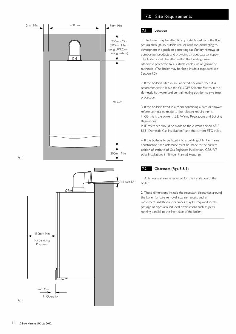
1. The boiler may be fitted to any suitable wall with the fluepassing through an outside wall or roof and discharging toatmosphere in a position permitting satisfactory removal ofcombustion products and providing an adequate air supply.The boiler should be fitted within the building unlessotherwise protected by a suitable enclosure i.e. garage orouthouse. (The boiler may be fitted inside a cupboard-seeSection 7.3).
2. If the boiler is sited in an unheated enclosure then it isrecommended to leave the ON/OFF Selector Switch in thedomestic hot water and central heating position to give frostprotection.
3. If the boiler is fitted in a room containing a bath or showerreference must be made to the relevant requirements.In GB this is the current I.E.E. Wiring Regulations and BuildingRegulations.In IE reference should be made to the current edition of I.S.813 “Domestic Gas Installations” and the current ETCI rules.
4. If the boiler is to be fitted into a building of timber frameconstruction then reference must be made to the currentedition of Institute of Gas Engineers Publication IGE/UP/7(Gas Installations in Timber Framed Housing).
7.2 Clearances (Figs. 8 & 9)
1. A flat vertical area is required for the installation of theboiler.
2. These dimensions include the necessary clearances aroundthe boiler for case removal, spanner access and airmovement. Additional clearances may be required for thepassage of pipes around local obstructions such as joistsrunning parallel to the front face of the boiler.
200mm Min
780mm
450mm5mm Min
5mm Min
450mm Min
For ServicingPurposes
Fig. 8
Fig. 9In Operation
5mm Min
200mm Min(300mm Min if
using 80/125mmflueing system)
At Least 1.5°

15
7.0 Site Requirement
© Baxi Heating UK Ltd 2012
7.3 Ventilation of Compartments
1. Where the appliance is installed in a cupboard orcompartment, no air vents are required.
2. BS 5440: Part 2 refers to room sealed appliancesinstalled in compartments. The appliance will run sufficientlycool without ventilation.
7.4 Gas Supply
1. The gas installation should be in accordance with therelevant standards. In GB this is BS 6891. In IE this is thecurrent edition of I.S. 813 “Domestic Gas Installations”.
2. The connection to the appliance is a 22mm copper taillocated at the rear of the gas service cock (Fig. 10).
3. Ensure that the pipework from the meter to theappliance is of adequate size. Do not use pipes of asmaller diameter than the boiler gas connection (22mm).
7.5 Electrical Supply
1. External wiring must be correctly earthed, polarised andin accordance with relevant regulations/rules. In GB this isthe current I.E.E. Wiring Regulations. In IE reference shouldbe made to the current edition of ETCI rules.
2. The mains supply is 230V ~ 50Hz fused at 3A.
NOTE: The method of connection to the electricitysupply must facilitate complete electrical isolation of theappliance.
Connection may be via a fused double-pole isolatorwith a contact separation of at least 3mm in all polesand servicing the boiler and system controls only.
3. When the system includes an indirect domestic hotwater cylinder it is recommended that a cylinderthermostat is used in conjunction with a 3 port 2 positionvalve or 2 port zone valve.
7.6 Bath & Shower Rooms
1. If the boiler is fitted in a room containing a bath orshower and NOT FITTED with any optional integral timeror thermostat, it can be fitted in zone 2, (Figs. 11 & 12show zone dimensions for a bathtub. For other examplesrefer to the Current I.E.E. Wiring Regulations) referencemust be made to the relevant requirements.In GB this is the current I.E.E. Wiring Regulations andBuilding Regulations.In IE reference should be made to the current edition of I.S.813 “Domestic Gas Installations” and the current ETCIrules.
Fig. 10
Gas Service Cock
Zone 2
Zone 1
Zone 0
Zone 2
Zone 2
WindowRecess
WindowRecess
0.6 m
Ceiling
Outside Zones
Zone 2Zone 1
Zone 0
2.25 m
Window RecessZone 2
0.6 m
Fig. 11
Fig. 12
In GB Only
In GB Only

16
7.0 Site Requirements
© Baxi Heating UK Ltd 2012
7.7 Condensate Drain
FAILURE TO INSTALL THE CONDENSATEDISCHARGE PIPEWORK CORRECTLY WILL AFFECTTHE RELIABLE OPERATION OF THE BOILER.
CAREFUL CONSIDERATION MUST BE GIVEN TO THEPOSSIBILITY OF THE PIPEWORK BEING SUBJECT TOFREEZING CONDITIONS AND APPROPRIATEMEASURES TAKEN TO PREVENT BLOCKAGE.CORRECT INSTALLATION IN ACCORDANCE WITHTHIS SECTION WILL CONSIDERABLY MINIMISE THELIKELIHOOD OF BLOCKAGE AND SUBSEQUENTBOILER LOCK-OUT.
A CONDENSATE DISCHARGE PUMP AND PIPE ‘TRACEHEATING’ ARE AVAILABLE AS ACCESSORIES - seeparagraphs 7.7.12 to 7.715 for further details.
The condensate discharge pipe MUST NOT RISE at anypoint along its length. There MUST be a fall of AT LEAST2.5° (50mm per metre) along the entire run EXCEPTwhen employing a suitable condensate pump in basementand cellar or similar applications.
The boiler condensate trap incorporates a seal of 75mm,therefore it is unnecessary to install an air break and trapin the discharge pipework.
1. The condensate outlet will accept 21.5mm (3/4in) plasticoverflow pipe. It is strongly recommended that thisdischarges internally into the household drainage system. Where this is not possible, discharge into an outside drain ispermissible providing every possible precaution is taken toprevent freezing.
2. Ensure the discharge of condensate complies with anynational or local regulations in force. BS 6798 & Part H1 ofthe Building Regulations give further detailed guidance.
3. The discharge pipe should be run in a proprietary drain pipematerial e.g. PVC, PVC-U, ABS, PVC-C or PP.
4. Metal pipework is NOT suitable for use in condensatedischarge systems.
5. The pipe should be a minimum of 21.5mm diameter andmust be supported using suitably spaced clips of the correctdesign to prevent sagging.
6. It is advisable that the full length of condensate pipe is runinternally and preferably be less than 3 metres.
7. Internal runs greater than 3 metres or runs in cold areasshould use 32mm waste pipe.
8. External runs MUST be a MINIMUM of 32mm and fullyinsulated with material suitable for external use.
9. If the boiler is fitted in an unheated location the entirecondensate discharge pipe should be treated as an externalrun and sized and insulated accordingly.
10. In all cases discharge pipe must be installed to aid disposalof the condensate. To reduce the risk of condensate beingtrapped, as few bends and fittings as possible should be usedand any burrs on cut pipe removed.
21.5mm
2.5° Minimum fall
i) Termination to an internal soil andvent pipe
450mm min*
Boiler
2.5° Minimum fall
ii) External termination via internal discharge branch e.g sink waste - downstream*
SinkPipe must terminate abovewater level but belowsurrounding surface. Cutend at 45°
50mm per metre of pipe run
50mm per metre of pipe run
*450mm is applicable toproperties up to 3 storeys. For multi-storey buildinginstallations consult BS 6798.
Examples are shown of the following methods of termination:-i) to an internal soil & vent pipeii) via an internal discharge branch (e.g. sink waste) downstream of the trapiii) to a drain or gullyiv) to a purpose made soakawayv) pumped into an internal discharge branch (e.g. sink waste) downstream of the trapvi) pumped into an external soil & vent pipevii) to a drain or gully with extended external run & trace heating
It is strongly recommended to discharge internally into the household drainage system. If connecting to a rain water drain, that drain MUST discharge into a foul drain.
*It is NOT RECOMMENDEDto connect upstream of thesink or other waste waterreceptacle !
32mm Insulation
17
7.0 Site Requirement
© Baxi Heating UK Ltd 2012
7.7 Condensate Drain (cont.)
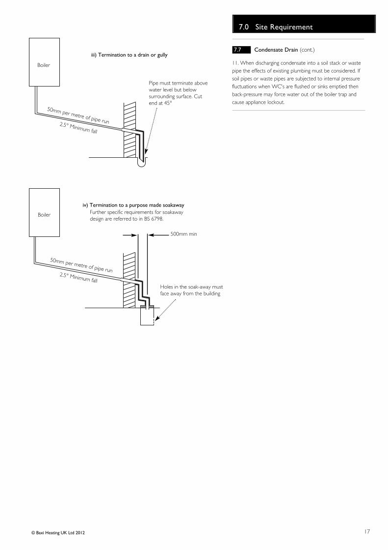
11. When discharging condensate into a soil stack or wastepipe the effects of existing plumbing must be considered. Ifsoil pipes or waste pipes are subjected to internal pressurefluctuations when WC's are flushed or sinks emptied thenback-pressure may force water out of the boiler trap andcause appliance lockout.
Boiler
2.5° Minimum fall
iii) Termination to a drain or gully
Boiler
500mm min
2.5° Minimum fall
iv) Termination to a purpose made soakaway
Holes in the soak-away mustface away from the building
50mm per metre of pipe run
50mm per metre of pipe run
Further specific requirements for soakawaydesign are referred to in BS 6798.
Pipe must terminate abovewater level but belowsurrounding surface. Cutend at 45°

18
7.0 Site Requirement
© Baxi Heating UK Ltd 2012
7.7 Condensate Drain (cont.)
12. A boiler discharge pump is available, ‘MULTIFIT’ part no. 720648301. This pump will dispose of bothcondensate & high temperature water from the relief valve.It has a maximum head of 5 metres. Follow the instructionssupplied with the pump.
13. Condensate Drain Pipe ‘Trace Heating’ Elements areavailable in various lengths. ‘MULTIFIT’ part nos.:-
1 metre 7206444012 metre 7206641013 metre 7206642015 metre 720664401*
*Where the drain is between 3 & 5 metres a 5 metre kit canbe used and “doubled back” upon itself.
14. It is possible to fit the element externally on thecondensate drain or internally as detailed in the instructionsprovided.
15. The fitting of a ‘Trace Heating’ Element is NOT asubstitute for correct installation of the condensate drain.ALL requirements in this section must still be adhered to.
Boiler
vi) pumped into an external soil & vent pipe
2.5° Minimum fall
50mm per metre of pipe run
Condensate Pump
Unheated Location(e.g. Garage)
Basement or similar(heated)
Boiler
2.5° Minimum fall
50mm per metre of pipe run Pipe must terminate abovewater level but belowsurrounding surface. Cutend at 45°
The ‘Trace Heating’ elementmust be installed in accordancewith the instructions supplied.External runs & those inunheated locations still requireinsulation.
vii) to a drain or gully with extended external run & trace heating
Boiler
v) pumped into an internal discharge branch(e.g. sink waste) downstream of the trap
Pipe must terminate abovewater level but belowsurrounding surface. Cutend at 45°
2.5° Minimum fall
50mm per metre of pipe run
Condensate Pump
Sink
Basement or similar(heated)

19
7.0 Site Requirements
© Baxi Heating UK Ltd 2012
7.8 Flue (Figs. 17 & 18)
NOTE: Due to the nature of the boiler a plume of watervapour will be discharged from the flue. This should betaken into account when siting the flue terminal.
1. The following guidelines indicate the general requirementsfor siting balanced flue terminals. For GB recommendationsare given in BS 5440 Pt 1. For IE recommendations are givenin the current edition of I.S. 813 “Domestic GasInstallations”.
2. If the terminal discharges onto a pathway or passageway,check that combustion products will not cause a nuisanceand that the terminal will not obstruct the passageway.
3. If a terminal is less than 2 metres above a balcony, aboveground or above a flat roof to which people have access,then a suitable terminal guard must be provided.
*4. Reduction to the boundary is possible down to 25mmbut flue deflector part no. 5111068 must be used.
IMPORTANT:• Under car ports we recommend the use of the plume
displacement kit.• The terminal position must ensure the safe and
nuisance - free dispersal of combustion products.
N
I
I
G
F
M
I
AA
F
H
J,K
DE
H
Likely flue positions requiring a flue terminal guard
C
RA
I
J,K
I
L
S
B
T
U
Fig. 18
Fig. 17
300 minTerminalAssembly
Top View Rear Flue
Property Boundary Line
NOTE: The distance from a fanned draught appliance terminalinstalled parallel to a boundary may not be less than 300mm inaccordance with the diagram below
Opening Windowor Door
150mmMIN.
IMPORTANT: If fitting a PlumeDisplacement Flue Kit, the air inletmust be a minimum of 150mm fromany opening windows or doors (seeSection 9.0).
Fig. 18a
PlumeDisplacement Kit
Air Inlet
*
Terminal Position with Minimum Distance (Fig. 18) (mm)
A1 Directly below an opening, air brick, opening windows, etc. 300
B1 Above an opening, air brick, opening window etc. 300C1 Horizontally to an opening, air brick, opening window etc. 300D2 Below gutters, soil pipes or drain pipes. 25 (75)E2 Below eaves. 25 (200)F2 Below balconies or car port roof. 25 (200)G2 From a vertical drain pipe or soil pipe. 25 (150)H2 From an internal or external corner. 25 (300)I Above ground, roof or balcony level. 300J From a surface or boundary line facing a terminal. 600K From a terminal facing a terminal (Horizontal flue). 1200
From a terminal facing a terminal (Vertical flue). 600L From an opening in carport (e.g. door, window)
into the dwelling. 1200M Vertically from a terminal on the same wall. 1500N Horizontally from a terminal on the same wall. 300R From adjacent wall to flue (vertical only). 300S From an adjacent opening window (vertical only). 1000T Adjacent to windows or openings on pitched and flat roofs 600U Below windows or openings on pitched roofs 2000
1 In addition, the terminal should be no nearer than 150 mm to an opening in thebuilding fabric formed for the purpose of accommodating a built-in element such asa window frame.2 Only ONE 25mm clearance is allowed per installation. If one of the dimensionsD, E, F, G or H is 25mm then the remainder MUST be as shown in brackets, inaccordance with B.S.5440-1.
20
8.0 Flue Options
© Baxi Heating UK Ltd 2012
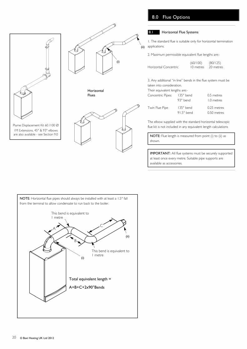
8.1 Horizontal Flue Systems
1. The standard flue is suitable only for horizontal terminationapplications.
2. Maximum permissible equivalent flue lengths are:-
(60/100) (80/125)Horizontal Concentric 10 metres 20 metres
3. Any additional “in line” bends in the flue system must betaken into consideration. Their equivalent lengths are:-Concentric Pipes: 135° bend 0.5 metres
93° bend 1.0 metres
Twin Flue Pipe 135° bend 0.25 metres91.5° bend 0.50 metres
The elbow supplied with the standard horizontal telescopicflue kit is not included in any equivalent length calculations
NOTE: Flue length is measured from point (i) to (ii) asshown.
IMPORTANT: All flue systems must be securely supportedat least once every metre. Suitable pipe supports areavailable as accessories.
HorizontalFlues
(ii)
(i)
Plume Displacement Kit 60 /100 Ø
1M Extensions, 45° & 93° elbowsare also available - see Section 9.0
NOTE: Horizontal flue pipes should always be installed with at least a 1.5° fallfrom the terminal to allow condensate to run back to the boiler.
(ii)
(i)
This bend is equivalent to1 metre
Total equivalent length =
A+B+C+2x90°Bends
B
AC
This bend is equivalent to1 metre
21
8.0 Flue Options
© Baxi Heating UK Ltd 2012
VerticalFlues
VerticalFlues(Twin Pipe)
(ii)
(i)
(ii)
(i)
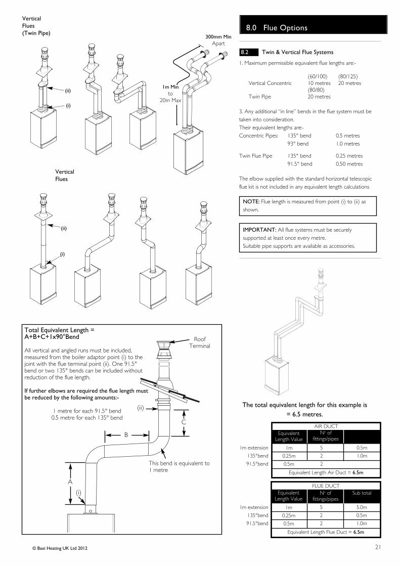
8.2 Twin & Vertical Flue Systems
1. Maximum permissible equivalent flue lengths are:-
(60/100) (80/125)Vertical Concentric 10 metres 20 metres
(80/80)Twin Pipe 20 metres
3. Any additional “in line” bends in the flue system must betaken into consideration. Their equivalent lengths are:-Concentric Pipes: 135° bend 0.5 metres
93° bend 1.0 metres
Twin Flue Pipe 135° bend 0.25 metres91.5° bend 0.50 metres
The elbow supplied with the standard horizontal telescopicflue kit is not included in any equivalent length calculations
NOTE: Flue length is measured from point (i) to (ii) asshown.
IMPORTANT: All flue systems must be securely supported at least once every metre. Suitable pipe supports are available as accessories.
The total equivalent length for this example is= 6.5 metres.
1m extension
135°bend
91.5°bend
1m
0.25m
0.5m
5
2
2
5.0m
0.5m
1.0m
AIR DUCTNo of
fittings/pipes
Sub total
EquivalentLength Value
Equivalent Length Air Duct = 6.5m
1m extension
135°bend
91.5°bend
1m
0.25m
0.5m
5
2
2
5.0m
0.5m
1.0m
FLUE DUCTNo of
fittings/pipesSub totalEquivalent
Length Value
Equivalent Length Flue Duct = 6.5m
(ii)
(i)
C
RoofTerminal
A
B
This bend is equivalent to1 metre
Total Equivalent Length =A+B+C+1x90°Bend
All vertical and angled runs must be included,measured from the boiler adaptor point (i) to thejoint with the flue terminal point (ii). One 91.5°bend or two 135° bends can be included withoutreduction of the flue length.
If further elbows are required the flue length mustbe reduced by the following amounts:-
1 metre for each 91.5° bend0.5 metre for each 135° bend
300mm MinApart
1m Minto
20m Max

22
8.0 Flue Options
© Baxi Heating UK Ltd 2012
A
BK,K1
RDC
N
U,W
S
L
H
J
M
E
G F
P
8.3 Flue Accessories
A2
Key Accessory Size Code NoFLUE GROUP AConcentric Flue System 100mm diameterA3 Telescopic Internal Flue Kit 315-500mm 5119654A2 Telescopic Flue (incl elbow) 5118069A Horizontal Flue Terminal (incl elbow) 5118489B Flue Extension 1000mm 5111074C Flue Bend 93° 5111075D Flue Bend (pair) 135° 5111085U Pipe Support (painted) 100mmØ 5111080P Wall Liner 5111067S Flue Terminal Deflector 5111068
FLUE GROUP NTwin Flue System 80mm diameterE Flue Extension (pair) 1000mm 5111087F Flue Bend (pair) 90° 5111072G Flue Bend (2 pair) 135° 5111086J Vertical Flue Boiler Adaptor Kit 720089801H Vertical Flue Adaptor 5111084Y Flue Horizontal Terminal Kit 5120172W Pipe Support (pair) 80mm 5111081
FLUE GROUP GFlue System 80/125mm diameterA4 Horizontal Flue Kit 5118580B Straight Extension Kit 1000mm 5118584D Bend Kit (pair) 135° 5118597C Bend 91.5° 5118588R Vertical Flue Adaptor 5111070
FLUE GROUP A, N, GVertical Flue KitsK Vertical Flue Terminal (use with Group G) 5111078K1 Vertical Flue Terminal (use with Group A) 5118576L Pitch Roof Flashing 5122151M Roof Cover Plate 246143N Flat Roof Flashing 246144
A3
A4
Y
23
8.0 Flue Options
© Baxi Heating UK Ltd 2012
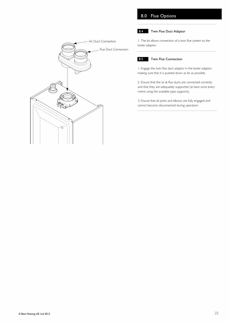
8.4 Twin Flue Duct Adaptor
1. The kit allows connection of a twin flue system to theboiler adaptor.
8.5 Twin Flue Connection
1. Engage the twin flue duct adaptor in the boiler adaptor,making sure that it is pushed down as far as possible.
2. Ensure that the air & flue ducts are connected correctlyand that they are adequately supported (at least once everymetre using the available pipe supports).
3. Ensure that all joints and elbows are fully engaged andcannot become disconnected during operation.
Flue Duct Connection
Air Duct Connection
24
8.0 Flue Options
© Baxi Heating UK Ltd 2012
Fig. 19
100mm
685mm
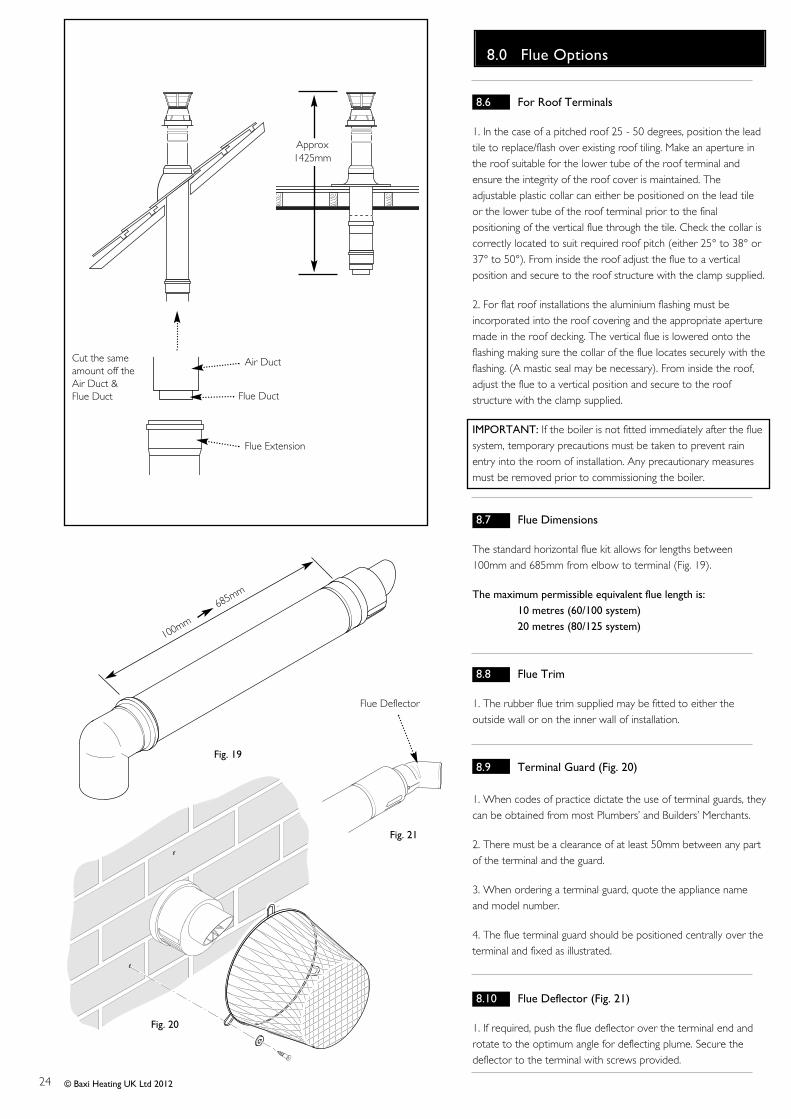
8.6 For Roof Terminals
1. In the case of a pitched roof 25 - 50 degrees, position the leadtile to replace/flash over existing roof tiling. Make an aperture inthe roof suitable for the lower tube of the roof terminal andensure the integrity of the roof cover is maintained. Theadjustable plastic collar can either be positioned on the lead tileor the lower tube of the roof terminal prior to the finalpositioning of the vertical flue through the tile. Check the collar iscorrectly located to suit required roof pitch (either 25° to 38° or37° to 50°). From inside the roof adjust the flue to a verticalposition and secure to the roof structure with the clamp supplied.
2. For flat roof installations the aluminium flashing must beincorporated into the roof covering and the appropriate aperturemade in the roof decking. The vertical flue is lowered onto theflashing making sure the collar of the flue locates securely with theflashing. (A mastic seal may be necessary). From inside the roof,adjust the flue to a vertical position and secure to the roofstructure with the clamp supplied.
IMPORTANT: If the boiler is not fitted immediately after the fluesystem, temporary precautions must be taken to prevent rainentry into the room of installation. Any precautionary measuresmust be removed prior to commissioning the boiler.
8.7 Flue Dimensions
The standard horizontal flue kit allows for lengths between100mm and 685mm from elbow to terminal (Fig. 19).
The maximum permissible equivalent flue length is: 10 metres (60/100 system)20 metres (80/125 system)
8.8 Flue Trim
1. The rubber flue trim supplied may be fitted to either theoutside wall or on the inner wall of installation.
8.9 Terminal Guard (Fig. 20)
1. When codes of practice dictate the use of terminal guards, theycan be obtained from most Plumbers’ and Builders’ Merchants.
2. There must be a clearance of at least 50mm between any partof the terminal and the guard.
3. When ordering a terminal guard, quote the appliance nameand model number.
4. The flue terminal guard should be positioned centrally over theterminal and fixed as illustrated.
8.10 Flue Deflector (Fig. 21)
1. If required, push the flue deflector over the terminal end androtate to the optimum angle for deflecting plume. Secure thedeflector to the terminal with screws provided.
Fig. 20
Flue Extension
Air Duct
Flue Duct
Cut the sameamount off theAir Duct &Flue Duct
Approx1425mm
Flue Deflector
Fig. 21
25
9.0 Plume Displacement
© Baxi Heating UK Ltd 2012
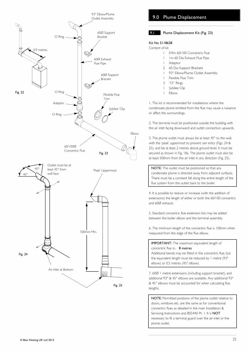
9.1 Plume Displacement Kit (Fig. 23)
Kit No 5118638Content of kit
1 0.9m 60/100 Concentric Flue1 1m 60 Dia Exhaust Flue Pipe1 Adaptor2 60 Dia Support Brackets1 93° Elbow/Plume Outlet Assembly1 Flexible Flue Trim3 “O” Rings1 ‘Jubilee Clip1 Elbow
1. This kit is recommended for installations where thecondensate plume emitted from the flue may cause a nuisanceor affect the surroundings.
2. The terminal must be positioned outside the building withthe air inlet facing downward and outlet connection upwards.
3. The plume outlet must always be at least 45° to the wall,with the ‘peak’ uppermost to prevent rain entry (Figs. 24 &25), and be at least 2 metres above ground level. It must besecured as shown in Fig. 18a. The plume outlet must also beat least 500mm from the air inlet in any direction (Fig. 25).
NOTE: The outlet must be positioned so that anycondensate plume is directed away from adjacent surfaces.There must be a constant fall along the entire length of theflue system from the outlet back to the boiler.
4. It is possible to reduce or increase (with the addition ofextensions) the length of either or both the 60/100 concentricand 60Ø exhaust.
5. Standard concentric flue extension kits may be addedbetween the boiler elbow and the terminal assembly.
6. The minimum length of the concentric flue is 100mm whenmeasured from the edge of the flue elbow.
IMPORTANT: The maximum equivalent length ofconcentric flue is:- 8 metresAdditional bends may be fitted in the concentric flue, butthe equivalent length must be reduced by 1 metre (93°elbow) or 0.5 metres (45° elbow).
7. 60Ø 1 metre extensions (including support bracket), andadditional 93° & 45° elbows are available. Any additional 93°& 45° elbows must be accounted for when calculating fluelengths.
NOTE: Permitted positions of the plume outlet relative todoors, windows etc. are the same as for conventionalconcentric flues as detailed in the main Installation &Servicing Instructions and BS5440 Pt. 1. It is NOTnecessary to fit a terminal guard over the air inlet or theplume outlet.
Air Inlet at Bottom
‘Peak’ Uppermost
Fig. 24
Fig. 25
500mm Min.
45°
45°Outlet must be atleast 45° fromwall face
93° Elbow/PlumeOutlet Assembly
60Ø ExhaustFlue Pipe
60Ø SupportBracket
60Ø SupportBracket
Flexible FlueTrim
60/100ØConcentric Flue
Adaptor
O Ring
O Ring
O Ring
‘Jubilee’ Clip
0.9 metres
Fig. 23
Fig. 22
Elbow
26
9.0 Plume Displacement
© Baxi Heating UK Ltd 2012
Concentric 60/100 Flue
60Ø Exhaust
X
Y
Fig. 26
Fig. 27
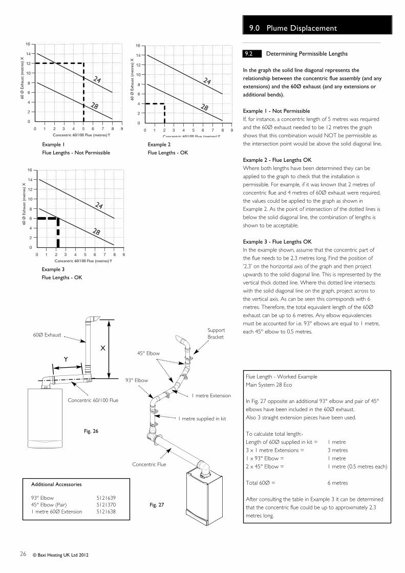
Flue Length - Worked ExampleMain System 28 Eco
In Fig. 27 opposite an additional 93° elbow and pair of 45°elbows have been included in the 60Ø exhaust.Also 3 straight extension pieces have been used.
To calculate total length:-Length of 60Ø supplied in kit = 1 metre3 x 1 metre Extensions = 3 metres1 x 93° Elbow = 1 metre2 x 45° Elbow = 1 metre (0.5 metres each)
Total 60Ø = 6 metres
After consulting the table in Example 3 it can be determinedthat the concentric flue could be up to approximately 2.3metres long.
Concentric Flue
SupportBracket
45° Elbow
93° Elbow
1 metre Extension
1 metre supplied in kit
Additional Accessories
93° Elbow 512163945° Elbow (Pair) 51213701 metre 60Ø Extension 5121638
9.2 Determining Permissible Lengths
In the graph the solid line diagonal represents therelationship between the concentric flue assembly (and anyextensions) and the 60Ø exhaust (and any extensions oradditional bends).
Example 1 - Not PermissibleIf, for instance, a concentric length of 5 metres was requiredand the 60Ø exhaust needed to be 12 metres the graphshows that this combination would NOT be permissible asthe intersection point would be above the solid diagonal line.
Example 2 - Flue Lengths OKWhere both lengths have been determined they can beapplied to the graph to check that the installation ispermissible. For example, if it was known that 2 metres ofconcentric flue and 4 metres of 60Ø exhaust were required,the values could be applied to the graph as shown inExample 2. As the point of intersection of the dotted lines isbelow the solid diagonal line, the combination of lengths isshown to be acceptable.
Example 3 - Flue Lengths OKIn the example shown, assume that the concentric part ofthe flue needs to be 2.3 metres long. Find the position of‘2.3’ on the horizontal axis of the graph and then projectupwards to the solid diagonal line. This is represented by thevertical thick dotted line. Where this dotted line intersectswith the solid diagonal line on the graph, project across tothe vertical axis. As can be seen this corresponds with 6metres. Therefore, the total equivalent length of the 60Øexhaust can be up to 6 metres. Any elbow equivalenciesmust be accounted for i.e. 93° elbows are equal to 1 metre,each 45° elbow to 0.5 metres.
2
0
2
4
6
8
10
12
14
60 Ø
Exh
aust
(m
etre
s) X
Concentric 60/100 Flue (metres) Y
0
16
1 3 4 65 7 98
24
28
2
0
2
4
6
8
10
12
14
60 Ø
Exh
aust
(m
etre
s) X
Concentric 60/100 Flue (metres) Y
0
16
1 3 4 65 7 98
24
28
2
0
2
4
6
8
10
12
14
60 Ø
Exh
aust
(m
etre
s) X
Concentric 60/100 Flue (metres)Y
0
16
1 3 4 65 7 98
24
28
Example 1
Flue Lengths - Not Permissible
Example 2
Flue Lengths - OK
Example 3
Flue Lengths - OK

27
9.0 Plume Displacement
© Baxi Heating UK Ltd 2012
Min. 2 metres
Fig. 28
Fig. 33
30mm
30mm Fig. 30
Fig. 32
Fig. 31
Adaptor
50mm
Flue Trim
Position of ‘Jubilee’ ClipscrewFig. 29
Spigot
9.3 General Fitting Notes
1. Cut a hole in the external wall which the concentric flueassembly will pass through. The hole should allow the flueto fall back to the boiler at an angle of at least 1.5°.
2. When completed the terminal must be at least 2 metresabove ground level (Fig. 28).
3. Measure and cut to size the concentric assembly and anyextensions that are being used.
4. Insert the concentric assembly through the hole fromoutside the building.
5. If required, the flexible flue trim should be fitted prior tothis as it cannot be fitted after. Use the large ‘Jubilee’ clip tosecure the trim to the flue (See Fig. 29, trim showndotted), with the screw part of the clip at the bottom.
6. Connect any extensions or elbows that are being usedto the concentric assembly. Engage the extension, elbowor concentric assembly in the boiler flue elbow. Fit theboiler flue elbow to the boiler adaptor.
7. Ensure that the concentric assembly and any extensionsfall back to the boiler at an angle of at least 1.5° and thatthe external air inlet is to the bottom.
8. Use suitable brackets to support the concentricassembly and any extensions, and make good inside andoutside.
9. The 60Ø exhaust can now be fitted. Slide the adaptorover the plain end of the 60Ø exhaust (Fig. 31) and engagethe exhaust in the terminal. Slide the adaptor down overthe spigot. Mark and drill the adaptor, using a 2mm bit, asshown in Fig. 30. Secure the adaptor to the spigot usingone of the screws supplied.
10. If it is necessary to shorten the 60Ø exhaust or any ofthe extensions, the excess material must be cut from theplain end of the pipe.
11. Determine the position of the 60Ø exhaust and markon the wall a suitable position for the support bracket. Ifextensions are being used, a support bracket is supplied ineach kit.
12. Drill the wall, and fit the bracket(s) using the plug andscrew provided.
13. Mark and drill the 60Ø exhaust, using a 2mm bit, asshown in Fig. 32. Complete the installation of the 60Øexhaust, securing in the brackets.
14. Fit the 93° elbow/plume outlet and secure with thetwo remaining screws supplied. Ensure the plume outlet isat least 45° to the wall and that the ‘peak’ is uppermost(Fig. 33).
28
9.0 Plume Displacement
© Baxi Heating UK Ltd 2012
9.3 General Fitting Notes (cont.)
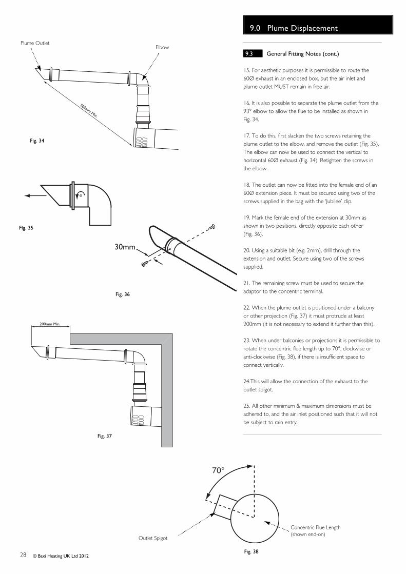
15. For aesthetic purposes it is permissible to route the60Ø exhaust in an enclosed box, but the air inlet andplume outlet MUST remain in free air.
16. It is also possible to separate the plume outlet from the93° elbow to allow the flue to be installed as shown in Fig. 34.
17. To do this, first slacken the two screws retaining theplume outlet to the elbow, and remove the outlet (Fig. 35).The elbow can now be used to connect the vertical tohorizontal 60Ø exhaust (Fig. 34). Retighten the screws inthe elbow.
18. The outlet can now be fitted into the female end of an60Ø extension piece. It must be secured using two of thescrews supplied in the bag with the ‘Jubilee’ clip.
19. Mark the female end of the extension at 30mm asshown in two positions, directly opposite each other (Fig. 36).
20. Using a suitable bit (e.g. 2mm), drill through theextension and outlet. Secure using two of the screwssupplied.
21. The remaining screw must be used to secure theadaptor to the concentric terminal.
22. When the plume outlet is positioned under a balconyor other projection (Fig. 37) it must protrude at least200mm (it is not necessary to extend it further than this).
23. When under balconies or projections it is permissible torotate the concentric flue length up to 70°, clockwise oranti-clockwise (Fig. 38), if there is insufficient space toconnect vertically.
24.This will allow the connection of the exhaust to theoutlet spigot.
25. All other minimum & maximum dimensions must beadhered to, and the air inlet positioned such that it will notbe subject to rain entry.
500mm Min.
200mm Min.
30mm
Fig. 35
Fig. 36
Fig. 34
Fig. 37
Plume OutletElbow
70°
Fig. 38
Outlet Spigot
Concentric Flue Length(shown end-on)

29
10.0 Installation
© Baxi Heating UK Ltd 2012
10.1 Unpacking & Initial Preparation
The gas supply, gas type and pressure must be checked forsuitability before connection (see Section 7.4).
1. Remove staples, open flaps and remove cardboard sheet.Remove the polystyrene side pieces and literature. Twopeople can then lift out the boiler (Fig. 39).
2. After considering the site requirements (see Section 7.0) position the fixing template on the wallensuring it is level both horizontally and vertically.
3. Mark the position of the two most suitable fixing slots forthe wall plate and boiler lower fixing holes. It is preferable touse the vertical fixing slots.
4. Mark the position of the centre of the flue hole (rearexit). For side flue exit, mark as shown (Fig. 40).
5. If required, mark the position of the gas and water pipes.Remove the template.
6. Cut the hole for the flue (minimum diameter 116mm).
7. Drill the wall as previously marked to accept the wallplugs supplied. Secure the wall plate using the fixing screws.
8. Using a spirit level ensure that the plate is level beforefinally tightening the screws.
99. Connect the gas and water pipes to the valves on thewall plate using the copper tails supplied. Ensure that thesealing washers are fitted between the connections.
10.2 Flushing
1. Connect a tube to the central heating flow or return pipe(Fig. 41).
2. Flush thoroughly (see System Details, Section 6.1).
10.3 Fitting The Boiler
1. Lift the boiler using the Lifting Points as shown by theshaded areas (Fig. 43). The boiler should be lifted by TWOPEOPLE. Engage the slots at the top rear of the boiler onthe wall plate (Fig. 42) (see Safe Manual Handling page 5).
2. Ease the boiler forwards and remove the sealing capsfrom the boiler connections (Fig 43).
NOTE: A small amount of water may drain from theboiler once the caps are removed.
3. Insert the sealing washers between the valves and pipeson the wall plate and the boiler connections. The rubberwashers must be used on the gas connection.
4. Tighten all the connections.
Fig. 41
145mm
For Side Flue Exit
Central Heating Return
Flushing TubeWall Plate
Fig. 40
Fig. 39 Unpacking Procedure
Wall Plate
Suggested Lifting Pointsshown as shaded area Fig. 43
Remove Sealing Capsfrom under the Boiler

30
10.0 Installation
© Baxi Heating UK Ltd 2012
10.4 Fitting the Pressure Relief Discharge Pipe (Fig. 44)
1. Remove the discharge pipe from the kit.
2. Determine the routing of the discharge pipe in the vicinityof the boiler. Make up as much of the pipework as ispractical, including the discharge pipe supplied.
3. The pipework must be at least 15mm diameter and runcontinuously downwards to a discharge point outside thebuilding. See section 6.7 for further details.
4. Utilising one of the sealing washers, connect the dischargepipe to the adaptor and tighten the nut.
5. Complete the discharge pipework and route it to theoutside discharge point.
IMPORTANT: Make all soldered joints before connectingto the pressure relief valve.
10.5 Condensate Drain (see Section 7.7)
1. Connect the condensate drain to the trap outlet pipe.
Ensure the discharge of condensate complies with anynational or local regulations in force (see British Gas“Guidance Notes for the Installation of Domestic GasCondensing Boilers”.
2. The connection will accept 21.5mm (3/4in) plastic overflowpipe which should generally discharge internally into thehousehold drainage system. If this is not possible, dischargeinto an outside drain is acceptable.
10.6 Fitting The Flue
HORIZONTAL FLUE
1. The standard flue is suitable for lengths between 100mmminimum and 685mm maximum, as measured from the edgeof the flue elbow outlet to the joint between the terminaland air duct (Fig. 45).
2. Locate the flue elbow on the adaptor at the top of theboiler. Set the elbow to the required orientation (Fig. 47).
NOTE: The flue elbow is angled at 93 degrees to ensurea fall back to the boiler.
3. Measure the distance from the outside wall face to theelbow. This dimension will be known as ‘X’ (Fig. 48).
4. To dimension ‘X’ add 50mm. This dimension to be knownas ‘Y’.
IMPORTANT: Check all dimensions before cutting.
5. Mark dimension ‘Y’ on the flue as shown (Fig. 49).Carefully cut the waste material from the flue, ensuring thatthe ducts are square and free from burrs.
Fig. 44
Pressure Relief Valve
Discharge Pipe
Fig. 45
100mm
685mm
Fig. 49
Wall Thickness
(X)
Wall Thickness
(X)
Flue Elbow
Fig. 47
AdaptorApply Lubricant forease of assembly.
Ensure Elbow is fullyengaged into BoilerAdaptor
Fig. 48
Y
Flue
Waste

31
10.0 Installation
© Baxi Heating UK Ltd 2012
Slots at bottom
Inner Flue Support Bracket
Fig. 50
Fig. 51
Fig. 52
Apply Lubricant forease of assembly.
Ensure Flue is fullyengaged into FlueElbow
10.6 Fitting the Flue (Cont)
6. The inner flue duct support bracket may be in the wasteportion of the flue. In this case retrieve the bracket beforediscarding the waste.
7. Take the inner flue support bracket (if not already fitted)and engage it over the flue duct. This will centralise the flueand air ducts, and ease assembly (Fig. 51).
8. Insert the flue through the hole in the wall. Fit the elbowto the boiler adaptor, ensuring that it is pushed fully in.
9. Draw the flue back through the wall and engage it in theelbow. It may be necessary to use soap solution or similarto ease assembly of the elbow adaptor and flue (Fig. 51).
10. Ensure that the terminal is positioned with the slots tothe bottom (Fig. 52).
IMPORTANT: It is essential that the flue terminal is fittedas shown to ensure correct boiler operation and preventwater entering the flue.
11. Make good between the wall and air duct outside thebuilding.
12. Fit the flue trim if required, and if necessary fit a terminalguard (see Section 8.8 & 8.9).
CONCENTRIC VERTICAL FLUE
13. Once the length of the vertical concentric extension hasbeen determined mark and carefully cut off the excessmaterial. The cut end MUST be square and free of burrs toensure correct insertion into the boiler adaptor.
14. Measure 25mm from the end of the flue extension andapply a length of tape around the outer duct (Fig. 53).
15. Engage the extension into the adaptor up to thisposition (Fig. 54). Once the installation of the flue iscomplete and all support brackets are securely in placeremove the tape.
AdaptorApply Lubricant forease of assembly.
Ensure Extension isfully engaged intoBoiler Adaptor
25mm
Extension
Cut End
Fig. 53Tape
Fig. 54
32
10.0 Installation
© Baxi Heating UK Ltd 2012
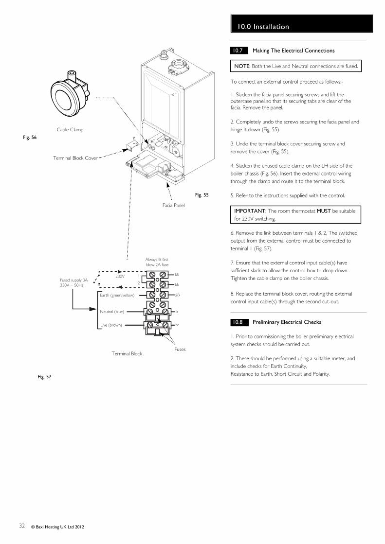
10.7 Making The Electrical Connections
NOTE: Both the Live and Neutral connections are fused.
To connect an external control proceed as follows:-
1. Slacken the facia panel securing screws and lift theoutercase panel so that its securing tabs are clear of thefacia. Remove the panel.
2. Completely undo the screws securing the facia panel andhinge it down (Fig. 55).
3. Undo the terminal block cover securing screw andremove the cover (Fig. 55).
4. Slacken the unused cable clamp on the LH side of theboiler chassis (Fig. 56). Insert the external control wiringthrough the clamp and route it to the terminal block.
5. Refer to the instructions supplied with the control.
IMPORTANT: The room thermostat MUST be suitablefor 230V switching.
6. Remove the link between terminals 1 & 2. The switchedoutput from the external control must be connected toterminal 1 (Fig. 57).
7. Ensure that the external control input cable(s) havesufficient slack to allow the control box to drop down.Tighten the cable clamp on the boiler chassis.
8. Replace the terminal block cover, routing the externalcontrol input cable(s) through the second cut-out.
10.8 Preliminary Electrical Checks
1. Prior to commissioning the boiler preliminary electricalsystem checks should be carried out.
2. These should be performed using a suitable meter, andinclude checks for Earth Continuity,Resistance to Earth, Short Circuit and Polarity.
Fig. 56
Fig. 57
Fig. 55
Terminal BlockFuses
Cable Clamp
Facia Panel
Always fit fast blow 2A fuse
Fused supply 3A230V ~ 50Hz
Neutral (blue)
Earth (green/yellow)
Live (brown)
1
2
230V
br
b
g/y
bk
bk
Terminal Block Cover
33
11.0 Commissioning
© Baxi Heating UK Ltd 2012
PumpAutomatic Air
Vent
Pressure Gauge
Screw
bar
0
1
2
3
4
Fig. 59
Selector Switch
Central Heating Temperature Control
CalibrationControl
Reset
bar
0
1
2
3
4
Pump
Fig. 61
Fig. 60Display
Heat ExchangerAutomatic Air Vent
Fig. 58
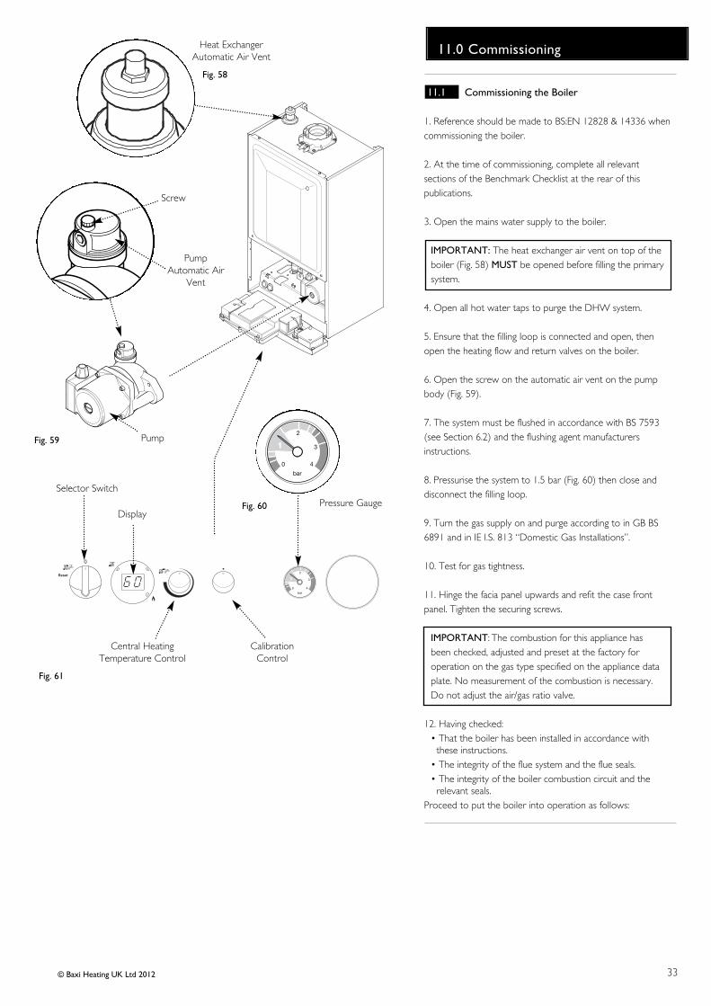
11.1 Commissioning the Boiler
1. Reference should be made to BS:EN 12828 & 14336 whencommissioning the boiler.
2. At the time of commissioning, complete all relevantsections of the Benchmark Checklist at the rear of thispublications.
3. Open the mains water supply to the boiler.
IMPORTANT: The heat exchanger air vent on top of theboiler (Fig. 58) MUST be opened before filling the primarysystem.
4. Open all hot water taps to purge the DHW system.
5. Ensure that the filling loop is connected and open, thenopen the heating flow and return valves on the boiler.
6. Open the screw on the automatic air vent on the pumpbody (Fig. 59).
7. The system must be flushed in accordance with BS 7593(see Section 6.2) and the flushing agent manufacturersinstructions.
8. Pressurise the system to 1.5 bar (Fig. 60) then close anddisconnect the filling loop.
9. Turn the gas supply on and purge according to in GB BS6891 and in IE I.S. 813 “Domestic Gas Installations”.
10. Test for gas tightness.
11. Hinge the facia panel upwards and refit the case frontpanel. Tighten the securing screws.
IMPORTANT: The combustion for this appliance hasbeen checked, adjusted and preset at the factory foroperation on the gas type specified on the appliance dataplate. No measurement of the combustion is necessary.Do not adjust the air/gas ratio valve.
12. Having checked:• That the boiler has been installed in accordance with
these instructions.• The integrity of the flue system and the flue seals.• The integrity of the boiler combustion circuit and the
relevant seals.Proceed to put the boiler into operation as follows:
34
11.0 Commissioning
© Baxi Heating UK Ltd 2012
Selector Switch Display
Reset
bar
0
1
2
3
4
Central Heating Temperature Control
Calibration Control
Fig. 63 Fig. 64
Fig. 65
Fig. 66 Fig. 67
Central Heating Temperature Control
Calibration ControlFig. 62
x 2
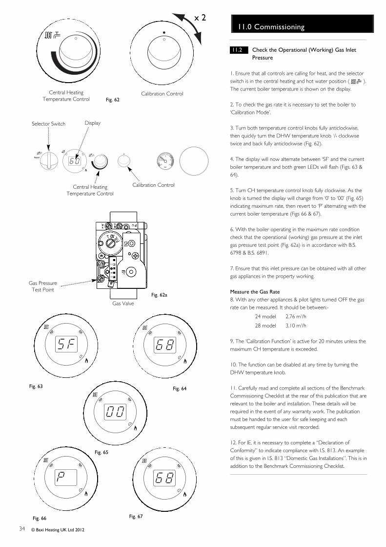
11.2 Check the Operational (Working) Gas Inlet
Pressure
1. Ensure that all controls are calling for heat, and the selectorswitch is in the central heating and hot water position ( ).The current boiler temperature is shown on the display.
2. To check the gas rate it is necessary to set the boiler to‘Calibration Mode’.
3. Turn both temperature control knobs fully anticlockwise,then quickly turn the DHW temperature knob 1/4 clockwisetwice and back fully anticlockwise (Fig. 62).
4. The display will now alternate between ‘SF’ and the currentboiler temperature and both green LEDs will flash (Figs. 63 &64).
5. Turn CH temperature control knob fully clockwise. As theknob is turned the display will change from ‘0’ to ‘00’ (Fig. 65)indicating maximum rate, then revert to ‘P’ alternating with thecurrent boiler temperature (Figs 66 & 67).
6. With the boiler operating in the maximum rate conditioncheck that the operational (working) gas pressure at the inletgas pressure test point (Fig. 62a) is in accordance with B.S.6798 & B.S. 6891.
7. Ensure that this inlet pressure can be obtained with all othergas appliances in the property working.
Measure the Gas Rate8. With any other appliances & pilot lights turned OFF the gasrate can be measured. It should be between:-
24 model 2.76 m3/h
28 model 3.10 m3/h
9. The ‘Calibration Function’ is active for 20 minutes unless themaximum CH temperature is exceeded.
10. The function can be disabled at any time by turning theDHW temperature knob.
11. Carefully read and complete all sections of the BenchmarkCommissioning Checklist at the rear of this publication that arerelevant to the boiler and installation. These details will berequired in the event of any warranty work. The publicationmust be handed to the user for safe keeping and eachsubsequent regular service visit recorded.
12. For IE, it is necessary to complete a “Declaration ofConformity” to indicate compliance with I.S. 813. An exampleof this is given in I.S. 813 “Domestic Gas Installations”. This is inaddition to the Benchmark Commissioning Checklist.
Gas Valve
Gas PressureTest Point
Fig. 62a

35
12.0 Completion
© Baxi Heating UK Ltd 2012
12.1 Completion
1. Instruct the user in the operation of the boiler andsystem including the integral timer, explaining theoperational sequence.
2. Set the central heating and hot water temperaturecontrol knobs to the requirements of the user.
3. Carefully read and complete all sections of theBenchmark Commissioning Checklist at the rear of thispublication that are relevant to the appliance andinstallation. These details will be required in the event ofany warranty work. The publication must be handed to theuser for safe keeping and each subsequent regular servicevisit recorded.
4. For IE, it is necessary to complete a “Declaration ofConformity” to indicate compliance with I.S. 813. Anexample of this is given in I.S. 813 “Domestic GasInstallations”. This is in addition to the BenchmarkCommissioning Checklist.
5. Hand over the Users Operating, Installation andServicing Instructions giving advice on the necessity ofregular servicing.
Fig. 68Facia Panel
Case Front Panel

36
13.0 Servicing
© Baxi Heating UK Ltd 2012
Case Front Panel
Fig. 69
Facia Panel SecuringScrews
Fig. 70Inner Door
Panel
Fig. 71
CondensateTrap
Sump
13 .1 Annual Servicing
1. For reasons of safety and economy, it is recommended thatthe boiler is serviced annually. Servicing must be performed bya competent person in accordance with B.S. 7967-4.
2. After servicing, complete the relevant Service Interval Recordsection of the Benchmark Commissioning Checklist at the rearof this publication.
IMPORTANT: During routine servicing, and after anymaintenance or change of part of the combustion circuit, thefollowing must be checked:-• The integrity of the complete flue system and the flue seals.• The integrity of the boiler combustion circuit and relevant
seals as described in Section 13.2.• The operational gas inlet pressure as described in Section
11.2.1 to 11.2.7 and the gas rate as described in 11.2.8.• The combustion performance as described in ‘Check the
Combustion Performance’ (13.1.4 to 13.1.6 below).
3. Competence to carry out Checking CombustionPerformanceB.S. 6798 ‘Specification for Installation & Maintenance of GasFired Boilers not exceeding 70kW’ advises that:-
• The person carrying out a combustion measurement should have been assessed as competent in the use of a flue gas analyser and the interpretation of the results.
• The flue gas analyser used should be one meeting the requirements of BS7927 or BS-EN50379-3 and be calibratedin accordance with the analyser manufacturers’ requirements.
• Competence can be demonstrated by satisfactory completion of the CPA1 ACS assessment, which covers the use of electronic portable combustion gas analysers in accordance with BS 7967, Parts 1 to 4.
Check the Combustion Performance (CO/CO2 ratio)4. Set the boiler to operate at maximum rate as described inSection 15.1.1 to 15.1.6.
5. Remove the plug from the flue sampling point, insert theanalyser probe and obtain the CO/CO2 ratio. This must beless than 0.004.
6. If the combustion reading (CO/CO2 ratio) is greater thanthis, and the integrity of the complete flue system andcombustion circuit seals has been verified, and the inlet gaspressure and gas rate are satisfactory either:• Perform the ‘Annual Servicing - Inspection’ (Section 13.2) &
re-check• Adjust the gas valve (Section 15.0) & re-check• Replace the gas valve (Section 14.23) & re-check
13.2 Annual Servicing - Inspection
1. Ensure that the boiler is cool.
2. Ensure that both the gas and electrical supplies to theboiler are isolated.
3. Slacken the screws securing the facia panel. Lift the outercasepanel so that its securing tabs are clear of the facia. Remove thepanel, allowing the facia to hinge down (Fig. 69).
4. Remove the screws securing the inner door panel. Lift thepanel slightly to disengage it from the studs on top of the case(Fig. 70).
5. Unscrew the sump from the bottom of the condensate trapassembly (Fig. 71) and remove any deposits from the sump andtrap. Clean as necessary and replace the sump.

37
13.0 Servicing
© Baxi Heating UK Ltd 2012
13.2 Annual Servicing - Inspection (Cont)
6. Undo the nut on the gas pipe at the gas/air inlet (Fig. 72)and the gas valve. Remove the pipe, taking care not to losethe sealing washers. Also remove the injector.
7. Disconnect the electrode lead caps, remove the strainrelief clip from the sensing lead and disconnect the lead.Remove the fan electrical plugs and pull the sensing pipe offthe fan.
8. Undo the screw securing the fan air inlet pipe to thebracket on the boiler top panel. Remove the pipe (Fig. 73).
9. Undo the five retaining nuts and washers and remove thefan, gas/air inlet and burner assembly (Figs. 74).
10. Carefully clean any debris from the heat exchanger.
11. Inspect the burner, electrode position, insulation, andgasket, cleaning or replacing if necessary. Clean any dirt ordust from the air box.
12. Reassemble in reverse order.
13. Complete the relevant Service Interval Record section ofthe Benchmark Commissioning Checklist at the rear of thispublication and then hand it back to the user.
Gas Pipe
Injector
Fan Air Inlet Pipe
Gas/Air Inlet
Fan, Gas/Air Inlet &Burner Assembly
Fig. 72
Fig. 73
Fig. 74

38
14.0 Changing Components
© Baxi Heating UK Ltd 2012
IMPORTANT: When changing components ensure thatboth the gas and electrical supplies to the boiler areisolated before any work is started. When thecomponent has been changed turn the selector switchfully anticlockwise against the spring pressure to thereset position and hold for 5 seconds to reset the boilerbefore recommissioning.
See Section 13.1 “Annual Servicing” for removal of casepanel, door etc.
14.1 Igniter (Fig. 75)
1. Disconnect the igniter feed plug and the electrode leads,noting their positions.
2. Undo the nuts and screws securing the igniter to theboiler top panel. Remove the igniter.
3. Fit the new igniter and reassemble in reverse order.
14.2 Electrode Assembly (Fig. 76)
1. Disconnect the electrode lead caps, remove the strainrelief clip from the sensing lead and disconnect the lead.
2. Undo the extended nuts securing the electrode assemblyto the combustion box panel and remove the assembly.
3. Check the condition of the sealing gasket and replace ifnecessary. Reassemble in reverse order.
Fig. 75
Igniter
Igniter FeedPlug
ElectrodeLeads
Fig. 76
SparkElectrode
ElectrodeLeads
SealingGasket

39
14.0 Changing Components
© Baxi Heating UK Ltd 2012
14.3 Fan
1. Undo the nut on the gas pipe at the gas/air inlet (Fig. 77)and the gas valve. Remove the pipe, taking care not to losethe sealing washers. Also remove the injector.
2. Disconnect the electrode lead caps, remove the strainrelief clip from the sensing lead and disconnect the lead.Remove the fan electrical plugs and pull the sensing pipe offthe fan.
3. Undo the screw securing the fan air inlet pipe to thebracket on the boiler top panel. Remove the pipe (Fig. 78).
4. Undo the five retaining nuts and washers and remove thefan, gas/air inlet and burner assembly (Fig. 79).
5. Remove the air box and gasket from the fan and transferto the new fan. Examine and replace the gasket if necessary.
6. Remove the four nuts and separate the fan from thegas/air inlet. Note the position of the orifice plate andexamine the gasket, replacing if necessary (Fig. 79).
7. Fit the new fan, ensuring that the orifice plate is correctlyfitted, and that the gasket is in position.
8. Examine the insulation around the burner and the heatexchanger gasket and replace if necessary.
9. Reassemble in reverse order, ensuring that the injector isin place and the sensing pipe is connected to the fan.
14.4 Injector (Fig. 77)
1. Undo the nut on the gas pipe at the gas/air inlet and thegas valve. Remove the pipe.
2. Extract and replace the injector and reassemble in reverseorder. Check the condition of the sealing washers, replacingif necessary.
Air Box
Fan
Gasket
Orifice Plate
Fig. 79
Fig. 77
Gas Pipe
Injector
Fan Air Inlet Pipe
Gas/Air Inlet
Gasket
Gasket
Gas/Air Inlet
Fig. 78

40
14.0 Changing Components
© Baxi Heating UK Ltd 2012
14.5 Burner (Fig. 80)
1. Undo the nut on the gas pipe at the gas/air inlet and thegas valve. Remove the pipe, taking care not to lose thesealing washers. Also remove the injector.
2. Disconnect the electrode lead caps, remove the strainrelief clip from the sensing lead and disconnect the lead.Remove the fan electrical plugs and pull the sensing pipe offthe fan.
3. Undo the screw securing the fan air inlet pipe to thebracket on the boiler top panel. Remove the pipe.
4. Undo the five retaining nuts and washers and remove thefan, gas/air inlet and burner assembly.
5. Remove the electrode assembly and draw the insulationpiece away. Undo the burner securing screws.
6. Fit the new burner and gasket, examine the insulation andheat exchanger gasket, replacing if necessary.
7. Reassemble in reverse order.
14.6 Insulation (Fig. 80)
1. Undo the nut on the gas pipe at the gas/air inlet and thegas valve. Remove the pipe, taking care not to lose thesealing washers. Also remove the injector.
2. Disconnect the electrode lead caps, remove the strainrelief clip from the sensing lead and disconnect the lead.Remove the fan electrical plugs and pull the sensing pipe offthe fan.
3. Undo the screw securing the fan air inlet pipe to thebracket on the boiler top panel. Remove the pipe.
4. Undo the five retaining nuts and washers and remove thefan, gas/air inlet and burner assembly.
5. Remove the electrode assembly and draw the insulationpiece away. Replace the insulation and reassemble inreverse order. Examine the heat exchanger gasket andreplace as necessary.
Fig. 80
Electrode Assembly
BurnerInsulation

41
14.0 Changing Components
© Baxi Heating UK Ltd 2012
14.7 Safety Thermostat (Fig. 81)
1. Pull the plug off the thermostat.
2. Remove the screws securing the thermostat to themounting plate on the flow pipe.
3. Reassemble in reverse order, ensuring that the plug ispushed fully on.
14.8 Central Heating Temperature Sensor (NTC) (Fig. 82)
1. Drain the boiler primary circuit. Pull the plug off the safetythermostat and disconnect the in-line plug in the sensor wire.
2. Unscrew the sensor from the heat exchanger. Reassemblethe new sensor in reverse order, using a new sealing washer.
14.9 Water Pressure Sensor (Fig. 83)
1. Drain the boiler primary circuit.
2. Disconnect the two wires from the sensor.
3. Unscrew the sensor from the hydraulic outlet assembly,examine the sealing washer and replace if necessary.
4. Reassemble in reverse order. The component is notpolarised - either wire will fit each terminal.
14.10 DHW Temperature Sensor (NTC) (Fig. 83)
1. Turn off the mains cold water supply tap and draw off theresidual domestic hot water.
2. Ease the retaining tab on the sensor away and disconnectthe electrical plug.
3. Unscrew the sensor from the hydraulic outlet assembly.Examine the sealing washer,replacing if necessary.
4. Reassemble in reverse order. The plug will only fit one way.
Central HeatingTemperature Sensor
Safety Thermostat
Fig. 81
Fig. 82
Fig. 83
Water Pressure SensorDomestic Hot WaterTemperature Sensor
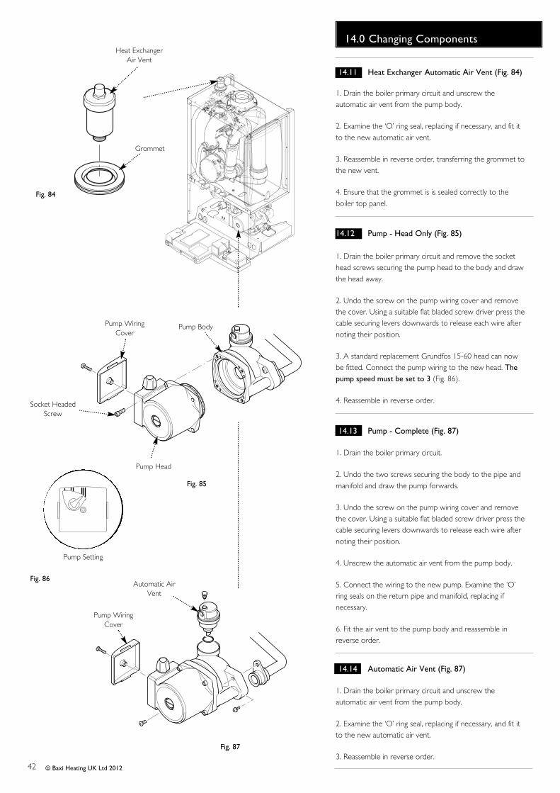
42
14.0 Changing Components
© Baxi Heating UK Ltd 2012
14.11 Heat Exchanger Automatic Air Vent (Fig. 84)
1. Drain the boiler primary circuit and unscrew theautomatic air vent from the pump body.
2. Examine the ‘O’ ring seal, replacing if necessary, and fit itto the new automatic air vent.
3. Reassemble in reverse order, transferring the grommet tothe new vent.
4. Ensure that the grommet is is sealed correctly to theboiler top panel.
14.12 Pump - Head Only (Fig. 85)
1. Drain the boiler primary circuit and remove the sockethead screws securing the pump head to the body and drawthe head away.
2. Undo the screw on the pump wiring cover and removethe cover. Using a suitable flat bladed screw driver press thecable securing levers downwards to release each wire afternoting their position.
3. A standard replacement Grundfos 15-60 head can nowbe fitted. Connect the pump wiring to the new head. Thepump speed must be set to 3 (Fig. 86).
4. Reassemble in reverse order.
14.13 Pump - Complete (Fig. 87)
1. Drain the boiler primary circuit.
2. Undo the two screws securing the body to the pipe andmanifold and draw the pump forwards.
3. Undo the screw on the pump wiring cover and removethe cover. Using a suitable flat bladed screw driver press thecable securing levers downwards to release each wire afternoting their position.
4. Unscrew the automatic air vent from the pump body.
5. Connect the wiring to the new pump. Examine the ‘O’ring seals on the return pipe and manifold, replacing ifnecessary.
6. Fit the air vent to the pump body and reassemble inreverse order.
14.14 Automatic Air Vent (Fig. 87)
1. Drain the boiler primary circuit and unscrew theautomatic air vent from the pump body.
2. Examine the ‘O’ ring seal, replacing if necessary, and fit itto the new automatic air vent.
3. Reassemble in reverse order.
Pump Setting
Socket HeadedScrew
Pump Head
Pump Body
Automatic AirVent
Fig. 85
Fig. 87
Fig. 86
Pump WiringCover
Pump WiringCover
Heat ExchangerAir Vent
Grommet
Fig. 84
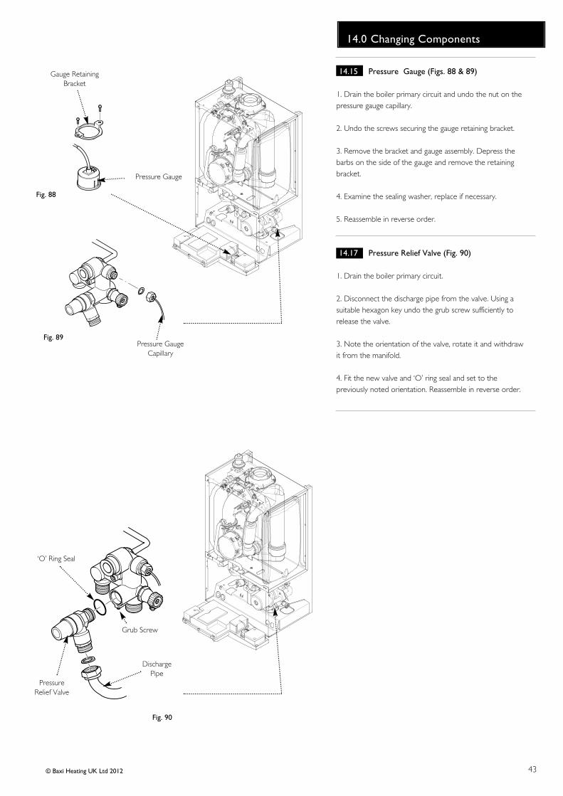
43
14.0 Changing Components
© Baxi Heating UK Ltd 2012
14.15 Pressure Gauge (Figs. 88 & 89)
1. Drain the boiler primary circuit and undo the nut on thepressure gauge capillary.
2. Undo the screws securing the gauge retaining bracket.
3. Remove the bracket and gauge assembly. Depress thebarbs on the side of the gauge and remove the retainingbracket.
4. Examine the sealing washer, replace if necessary.
5. Reassemble in reverse order.
14.17 Pressure Relief Valve (Fig. 90)
1. Drain the boiler primary circuit.
2. Disconnect the discharge pipe from the valve. Using asuitable hexagon key undo the grub screw sufficiently torelease the valve.
3. Note the orientation of the valve, rotate it and withdrawit from the manifold.
4. Fit the new valve and ‘O’ ring seal and set to thepreviously noted orientation. Reassemble in reverse order.
Pressure Gauge
Pressure GaugeCapillary
Gauge RetainingBracket
Fig. 89
Fig. 88
‘O’ Ring Seal
DischargePipe
Grub Screw
PressureRelief Valve
Fig. 90

44
14.0 Changing Components
© Baxi Heating UK Ltd 2012
14.18 P.C.B. (Figs. 91 & 92)
1. Note the settings of the temperature control knobs,rotate them fully anticlockwise and carefully pull them offthe drive pins.
2. Completely undo the screws securing the control boxcover and release the cover retaining barbs from their slots.Disengage the rear of the cover from the control box hingepin.
3. Note the position of all plugs and wires on the P.C.B. anddisconnect them.
4. Undo the securing screws and remove the P.C.B. Transferthe control knob drive pins to the new P.C.B. and turn themfully anticlockwise.
5. Reassemble in reverse order, ensuring that thetemperature controllers are reset to their previous positions.
14.19 Selector Switch (Figs. 91 & 92)
1. Note the setting of the selector switch knob and carefullypull it off the facia.
2. Completely undo the screws securing the control boxcover and release the cover retaining barbs from their slots.Disengage the rear of the cover from the control box hingepin.
3. Note the position of the electrical connections and theorientation of the switch. Remove the electrical connections.
4. Remove the screws securing the switch to the facia panel.
5. Fit the new switch, ensuring that it is correctly positionedand reassemble in reverse order.
Control Box Cover
P.C.B.
SelectorSwitch
Facia
Selector Switch Knob Temperature Control Knobs
Fig. 91
Fig. 92
Drive Pins

45
14.0 Changing Components
© Baxi Heating UK Ltd 2012
14.20 Gas Valve (Fig. 93)
IMPORTANT: After replacing the valve the CO2 must bechecked and adjusted as detailed in Section 15.0 Settingthe Gas Valve. Only change the valve if a suitablecalibrated combustion analyser is available, operated by acompetent person - see section 13.1.
1. Turn the gas cock off and undo the nut on the gas feedelbow under the boiler.
2. Remove the screws securing the gas valve to the boilerbottom panel.
3. Pull off the power lead, earth lead and sensing pipe.
4. Undo the nut on the gas pipe at the gas/air inlet and the gasvalve. Remove the pipe, taking care not to lose the sealingwashers. Remove the valve.
5. Remove the outlet adaptor and inlet pipe and transfer themto the new valve. Examine the ‘O’ ring seals, replace ifnecessary.
6. Reassemble in reverse order., ensuring that all seals are inplace and the injector is fitted.
NOTE: To assist the boiler to light prior to final setting,use a suitable hexagon key to wind out the Throttleadjustment screw until it is flush with the valve body, thenturn the screw 4 full turns clockwise (Fig. 93a). If the boilerwill not light, or the correct CO2 cannot be achievedcontact the ‘heateam’ technical helpline.
14.21 Expansion Vessel (Fig. 94)
1. Drain the boiler primary circuit and undo the nut on thevessel connection pipe.
2. Remove the screw retaining the air inlet pipe, and swing thepipe to one side.
3. Undo and remove the locknut and spring washer securingthe vessel spigot to the boiler lower panel.
4. Remove the bracket and vessel from the boiler.
5. Locate the retaining bracket on the upper flange of the newvessel and fit to the boiler.
6. Examine the sealing washer, replacing if necessary, andreassemble in reverse order.
Gas Valve
Gas FeedElbow
Fig. 93
Earth Lead
Expansion Vessel
Boiler ChassisLock Nut
SpringWasher
Fig. 94
Retaining Bracket
Sensing Pipe
Venturi InletPipe
Power Lead
Fig. 93a
ThrottleAdjustment Screw

46 © Baxi Heating UK Ltd 2012
Selector Switch Display
Reset
bar
0
1
2
3
4
Central Heating Temperature Control
Domestic Hot Water Temperature Control
Fig. 96 Fig. 97
Fig. 98 Fig. 99 Fig. 100
Central Heating Temperature Control
Calibration ControlFig. 95
x 2
Fig. 101
Flue Adaptor TestPoint
Plug
Analyser Probe
ThrottleAdjustment Screw(cover removed)
OffsetAdjustment Screw
(cap fitted)
Gas ValveFig. 102
If the CO2 is reset at minimumrate it must be rechecked atmaximum rate again and adjustedif required. If the CO2 is reset atmaximum rate it must berechecked at minimum rate andadjusted if required.
Do not turn the adjustmentscrews more than 1/8 of a turn ata time. Allow the analyser readingto settle before any furtheradjustment
Reduce CO2
at min. rateIncrease CO2
at min. rateReduce CO2
at max. rateIncrease CO2
at max. rate
15.0 Setting the Gas Valve
15.1 Setting the Gas Valve (CO2 check)
IMPORTANT: The CO2 must be only be checked andadjusted to set the valve if a suitable calibratedcombustion analyser is available, operated by acompetent person - see Section 13.1
1. The combustion (CO2) may be checked after running theboiler for several minutes. To do this it is necessary to setthe boiler to ‘Calibration Mode’.
2. Ensure that all external controls are calling for heat. Theactual current boiler temperature is shown on the display.
3. Turn both control knobs fully anticlockwise, then quicklyturn the right hand knob 1/4 clockwise twice and back fullyanticlockwise (Fig. 95).
4. The display will now alternate between ‘SF’ and thecurrent boiler temperature and both green LEDs will flash(Figs. 96 & 97).
5. Turn the left hand knob fully clockwise. As the knob isturned the display will change, indicating the fan speed.
6. The display will show ‘00’, indicating maximum rate, thenrevert to ‘P ‘ alternating with the current boiler temperature(Figs. 98, 99 & 100).
7. Remove the plug from the flue sampling test point. Insertthe analyser probe and allow sufficient time for the readingto settle (Fig. 101).
The CO2 should be 9.0% + 0.0 - 0.4
8. It is possible to alter the CO2 by adjustment of the gasvalve. Remove the plastic cover from the ThrottleAdjustment Screw. At maximum rate the ThrottleAdjustment Screw should be turned, using a suitablehexagon key, until the correct reading is obtained (Fig. 102). Turning clockwise will reduce the CO2. Anticlockwise willincrease th e CO2.
9. The CO2 must then be checked at minimum rate. Turnthe left hand knob fully anti-clockwise. As the knob is turnedthe display will change, indicating the fan speed. When thedisplay reads ‘ 0’ the boiler runs at minimum rate.
The CO2 should be 8.4% + 0.0 - 0.4
10. With the boiler on minimum, the Offset AdjustmentScrew must be altered, using a suitable hexagon key, afterremoving the cap (Fig. 102). Turning anti-clockwise willreduce the CO2. Clockwise will increase th e CO2.
11. The ‘Calibration Function’ is maintained for 20 minutesunless the maximum CH temperature is exceeded. Thefunction can be disabled at any time by turning the righthand knob.
12. Check the Combustion Performance (CO/CO2 ratio).This must be less than 0.004.
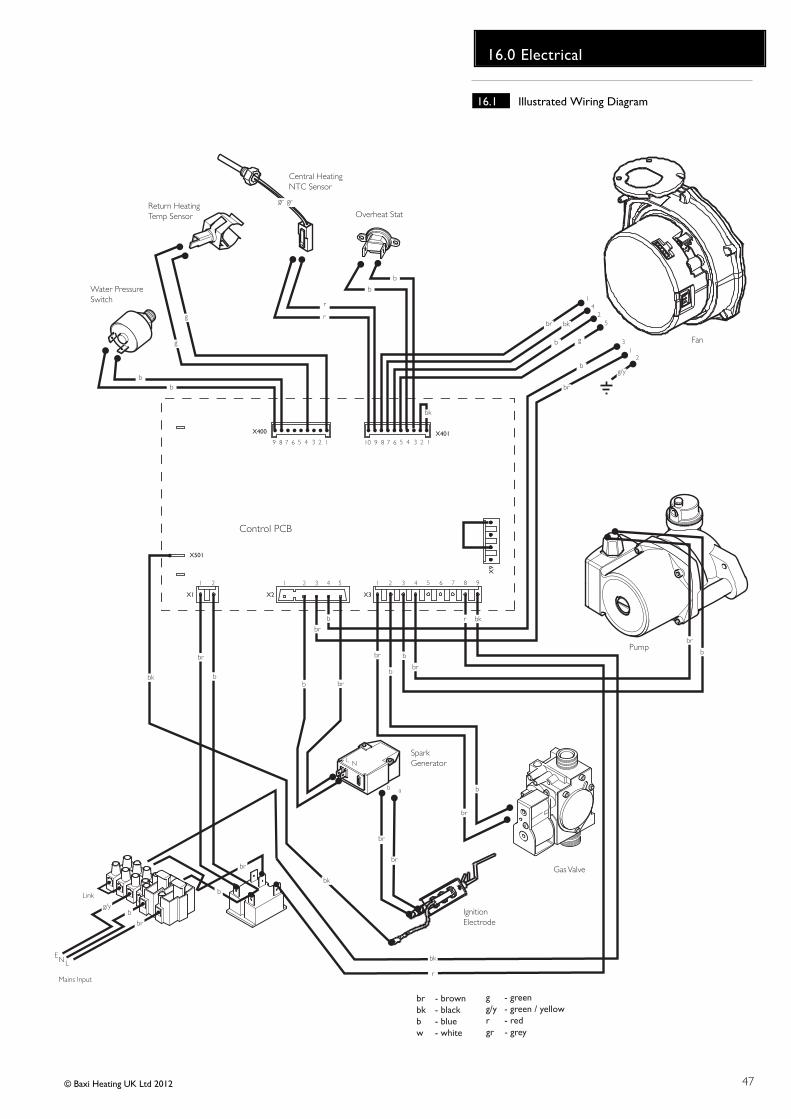
47
16.0 Electrical
© Baxi Heating UK Ltd 2012
- brown- black- blue- white
brbkbw
- green- green / yellow- red
gg/yr
Control PCB
X2 X3
X9
X501
1 21 2 33 44 55 6 7 8 9
X1
1 2
Return HeatingTemp Sensor
Central Heating NTC Sensor
Fan
Gas Valve
Overheat Stat
Pump
X400 X401
g
g
bb
r
r
b
b
bkbr
b g
b
br
g/y
b
br
b br
br
b
b
b
br
br
br
b
b
br
r bk
r
bk
Water PressureSwitch
SparkGenerator
IgnitionElectrode
9 8 7 6 5 4 3 2 1 910 8 7 6 5 4 3 2 1
NL
br
br
14
25
31
2
ab
Link
bg/y
br
Mains Input
br
b
bk
bk
bk
- greygr
gr gr
EN L
16.1 Illustrated Wiring Diagram

48
17.0 Short Parts List
© Baxi Heating UK Ltd 2012
Short Parts List
Key G.C. Description ManufacturersNo. No. Part No.
A Fan 5121447
B Electrode Assembly 5130293
C Gas Valve 720301001
D Burner 5130292
E Water Pressure Switch 5114748
F Pump 248042
G NTC Sensor 5114725
H Overheat Thermostat 5114729
J NTC Sensor 5130291
K Pressure Gauge 248090
L PCB 24 5131262
PCB 28 5131263
D
A
C
E
F
LK
B
J G H

49
18.0 Fault Finding
© Baxi Heating UK Ltd 2012
NOTE: When instructed to turn theselector to the reset position turn theselector switch fully anticlockwise againstthe spring pressure to the reset positionand hold for 5 seconds to reset theboiler.
18.1 Initial Fault Finding Checks
1. Check that gas, water and electrical supplies are availableat the boiler.
2. Electrical supply = 230V ~ 50 Hz.
3. CH water system pressurised to 0.5 bar minimum whenthe boiler is cold.
4. The preferred minimum gas pressure is 20 mbar.
5. Carry out electrical system checks, i.e. Earth Continuity,Resistance to Earth, Short Circuit and Polarity with a suitablemeter.
NOTE: These checks must be repeated after anyservicing or fault finding.
6. Ensure all external controls are calling for heat and checkall external and internal fuses. Before any servicing orreplacement of parts, ensure the gas and electrical suppliesare isolated.
18.2 Error Codes
1. If a fault occurs on the boiler an error code may be shownby the facia display.
2. The codes are either two or three digit, preceded by theletter 'E'. For example, code E133 will be displayed by 'E1'alternating with '33'. E50 is shown as 'E' then '50'
E20, E28 & E50 indicate faulty or incorrect components.
E110 shows overheat of the primary water.
E119 is displayed when the primary water pressure is lessthan 0.5 bar.
E133 indicates that the gas supply has been interrupted,ignition has failed or the flame has not been detected.
E125 is displayed in either of two situations:-i) If within 15 seconds of the burner lighting the boilertemperature has not changed by 1°.ii) If within 10 minutes of the burner lighting the boilertemperature twice exceeds the selected temperature by 30°.In these instances poor primary circulation is indicated.
3. By turning the selector switch to the 'Reset' position for aminimum of 5 seconds when E110 & E133 are displayed it ispossible to relight the boiler.
4. If this does not have any effect, or the codes are displayedregularly further investigation is required.
Central Heating NTC FaultIncorrect PCB FittedHot Water NTC Fault Safety Thermostat OperatedWater Pressure Switch Not OperatedCirculation Fault (Primary Circuit)Interruption Of Power Supply while in fault modeInterruption Of Gas Supply or Flame FailureFan or Fan Wiring Fault
E20E28E50E110E119E125E131E133E160
Table Of Error Codes

50
18.0 Fault Finding
© Baxi Heating UK Ltd 2012
Refer to Section 16.0 “Illustrated Wiring Diagram” for position of terminals and componentsCentral Heating - Follow operational sequence
Turn selector switch to The display illuminates
Error 20, 28 or 50 flashing
Error 119 flashing
Burner lights
Error 110 flashingError 133 flashing
Turn Central Heatingthermostat to Maximum.
Pump runs
Fan runs
Spark at ignition electrodes forup to 5 seconds and for 3
attempts
3-way valve is open to CentralHeating circuit
Go to section ‘A’
Go to section ‘E’
Ensure all controls (andintegral clock if fitted) are
calling for heat
Go to section ‘J’
Go to section ‘B’
Error 160 flashingGo to section ‘D’
Error 133 flashing
Burner does not stay alightsafter 5 seconds
Error 133 flashingGo to section ‘H’
Operation sequencesuccessful
If the error 110 is still flashing.Go to section ‘I’
Fan runs at correct speed
YES
YES
NO
NO
NO
YES
YES
YES
YES
YES
YES YES
YES
NO
YES YES
YES
YES
NO
NO
NO
NO
NO
Burner output modulates tomaintain the temperature set
Burner goes out
Go to section ‘C’
Ensure controls are set todemand and verify the
contacts are closed
Error 160 flashingGo to section ‘K’
YESGo to section ‘G’
Turn the selector switch toreset
Go to section ‘F’
YES
Check the Central HeatingNTC sensor
Go to section ‘E’
Fan stops after 10 secondsPump continues to run for 3
minutes (room thermostat open)
NO
NO
YES
NO
YES YES
Turn the selector switch toreset position for 5 seconds
NO
Error 125 flashingEnsure that primary
circulation is OK & thatthere is no blockage
YES

51
18.0 Fault Finding
© Baxi Heating UK Ltd 2012
Fault Finding Solutions Sections
Is there 230V at:
Is there 230V at:
Main terminals L and N Check electrical supply1. NO
Main terminal fuse Replace fuseReplace PCB
Displayilluminated
2. NO
PCB - X1 connectorterminals 1,2
Check wiring3. NO
NO
A
Pump Replace pump1. YES
PCB - X3 connector terminals 3 & 4 Replace PCB2. NO
Change pump supply cable
YES
B
CH system pressure less than 0.5 bar Re-pressurise system1. YES
Check the tap of the automatic airvent is opened
Open the automatic air vent2. NO
C
NO
YESFan connections correct at fan. PCB -X2 connector, is 230V AC acrossterminals 5 & 7
Fan jammed or faulty winding
Replace PCB
Replace fanYES
D
If pump jammed, release NO
NO
Replace waterpressure switch
Check connection water pressureswitch terminalCOM - NO and PCB connectorX400 terminals 3,4
YES
E20 or E50 - Temperature sensors faulty.Cold resistance approximately10kΩ @ 25° C (Temperature sensors)20kΩ @ 25° C (Flue sensor)(resistance reduces with increase in temp.)
E28 - Incorrect PCB fitted
NO
EReplace sensor or PCB (E28)

52
18.0 Fault Finding
© Baxi Heating UK Ltd 2012
Gas at burner Ensure gas is on and purged
Replace PCB
Replace gas valvePCB - X3 connector is 230V AC across
terminals 1 & 2YES
NO
NO
F
Replace PCBG
Check and correct if necessary1. Ignition electrode and lead2. Electrode connection3. Spark gap and position
voltage at PCB - X2 connector is110V AC across terminals 2 & 5(Note: from multimeter connect‘common’ to 2 & ‘volts’ to 5)Check wiring
YES
NO
Replace igniterYES
Check and correct the connection of thetube between the venturi and gas valve
1.
2.
Check and correct if necessary1. The mechanical set of the gas valve(CO2 values - see instruction)2. Flame sensing electrode and lead connections3. Flame sensing electrode position
Flame current should be more than 0.5 μ AReplace PCB
Replace PCB
YES
YES
Replace flame sensing electrodeNO
Check the gas supply pressure:For Natural Gas MINIMUM 17 mbar
IReplace safety thermostat
YESNOOverheat thermostat operated orfaulty, i.e. continuity across
thermostat terminals
Allow to cool. Continuityacross thermostat terminals
more than 1.5 ohm
2.
1.H

53© Baxi Heating UK Ltd 2012
18.0 Fault Finding
K
J
L
Is there 230V at:PCB - X3 connector terminals 5 & 6 central heating mode
Replace PCBNO
Change pump supply cable
YES
Fan connections correct at fan.PCB - X401 connector terminals 5,6,7 & 8
YESReplace fan
Temperature sensors faulty.Cold resistance approximately10kΩ @ 25° C (CH sensor)(resistance reduces with increase in temp.)
NOReplace sensor
YESIf pump is running the heat exchanger could beobstructed
Replace heat exchanger
1.
2.

GAS BOILER SYSTEM COMMISSIONING CHECKLISTThis Commissioning Checklist is to be completed in full by the competent person who commissioned the boiler as a means of demonstrating compliance with the appropriate Building Regulations and then handed to the customer to keep for future reference.
Failure to install and commission according to the manufacturer’s instructions and complete this Benchmark Commissioning Checklist will invalidate the warranty. Thisdoes not affect the customer’s statutory rights
Customer Name
Address
Boiler Make and Model
Boiler Serial Number
Commissioned by (print name)
Company Name
Company Address
To be completed by the customer on receipt of a Buildings Regulations Compliance Certificate*:
Building Regulations Notification Number (if applicable)
Time and Temperature Control to Heating Room Thermostat and Programmer/Timer
ProgrammableRoom Thermostat
Load/WeatherCompensation
Time and Temperature Control to Hot Water Cylinder Thermostat and Programmer/Timer
Fitted
Fitted
Fitted
Fitted
Yes
Yes
Yes
Yes
Yes
ppm Ratio
Yes
Yes
Yes
Yes
www.centralheating.co.uk
Yes
Temperature
No
No
Quantity
m /hr
mbar Gas Inlet Pressure
Gas Inlet Pressure (at maximum rate)
OR
OR
OR
OR% ORCO
OR
litres
Provided
Not Required
Not Required
Not Required
Not Required
Combination Boiler
Optimum StartControl
Heating Zone Valves
Hot Water Zone Valves
Thermostatic Radiator Valves
Automatic Bypass to System
Boiler Interlock
Telephone Number
Gas Safe Register Number
Telephone Number
Commissioning Date
The system has been flushed and cleaned in accordance with BS7593 and boiler manufacturer’s instructions
What inhibitor was used?
What system cleaner was used?
Gas Rate
Burner Operating Pressure (if applicable)
Central Heating Flow Temperature
Central Heating Return Temperature
Gas Rate
Burner Operating Pressure (at maximum rate)
Cold Water Inlet Temperature
Hot Water has been checked at all outlets
If required by the manufacturer, record the following
The heating and hot water system complies with the appropriate Building Regulations
The boiler and associated products have been installed and commissioned in accordance with manufacturer’s instructions
The operation of the boiler and system controls have been demonstrated to and understood by the customer
(To confirm satisfactory demonstration and receipt of manufacturer’s literature)
The manufacturer’s literature, including Benchmark Checklist and Service Record, has been explained and left with the customer
*All installations in England and Wales must be notified to Local Authority Building Control (LABC) either directly or through a Competent Persons Scheme. A Building Regulations Compliance Certificate will then be issued to the customer.
Heating and Hotwater Industry Council (HHIC)
Commissioning Engineer’s Signature
Customer’s Signature
Water Flow Rate
Is the installation in a hard water area? (above 200ppm)
If yes and if required by the manufacturer, has a water scale reducer been fitted?
The condensate drain has been installed in accordance with the manufacturer’s instructions and/or BS5545/BS6798
If the condensate pipe terminates externally, has the pipe diameter been increased and weatherproof insulation fitted?
What type of scale reducer has been fitted?
CONTROLS Tick the appropriate boxes
ALL SYSTEMS
CENTRAL HEATING MODE Measure and Record:
COMBINATION BOILERS ONLY
CONDENSING BOILERS ONLY
ALL INSTALLATIONS
DOMESTIC HOT WATER MODE Measure and Record
mbar
ft /hr
°C
°C
3
m /hr
mbar
3
3
mbar
ft /hr
l/min
°C
°C
3
CO2 CO/CO2
c
54
Service RecordIt is recommended that your heating system is serviced regularly and that the appropriate Service Interval Record is completed.
Service ProviderBefore completing the appropriate Service Record below, please ensure you have carried out the service as described in the manufacturer’s instructions.
Always use the manufacturer’s specified spare part when replacing controls.
Date:
Engineer Name:
Company Name:
Telephone No.
Gas Safe Register No.
Comments:
Signature:
Date:
Engineer Name:
Company Name:
Telephone No.
Gas Safe Register No.
Comments:
Signature:
Date:
Engineer Name:
Company Name:
Telephone No.
Gas Safe Register No.
Comments:
Signature:
Date:
Engineer Name:
Company Name:
Telephone No.
Gas Safe Register No.
Comments:
Signature:
Date:
Engineer Name:
Company Name:
Telephone No.
Gas Safe Register No.
Comments:
Signature:
Date:
Engineer Name:
Company Name:
Telephone No.
Operative ID No.
Comments:
Signature:
Date:
Engineer Name:
Company Name:
Telephone No.
Gas Safe Register No.
Comments:
Signature:
Date:
Engineer Name:
Company Name:
Telephone No.
Gas Safe Register No.
Comments:
Signature:
Date:
Engineer Name:
Company Name:
Telephone No.
Gas Safe Register No.
Comments:
Signature:
Date:
Engineer Name:
Company Name:
Telephone No.
Gas Safe Register No.
Comments:
Signature:
Service 1 Service 2
Service 3 Service 4
Service 5 Service 6
Service 7 Service 8
Service 9 Service 10
55

© Baxi Heating UK Ltd 2012 Comp No 5119528 - Iss 7 - 5/12
All descriptions and illustrations provided in this leaflet have been
carefully prepared but we reserve the right to make changes and
improvements in our products which may affect the accuracy of the
information contained in this leaflet. All goods are sold subject to our
standard Conditions of Sale which are available on request.
MAINA Trading Div is ion of Baxi Heat ing UK Ltd (3879156)Brooks House, Coventry Road, Warwick. CV34 4LLAfter Sales Service 0844 871 1570 Technical Enquiries 0844 871 1555Website www.mainheating.co.uke&oe