Embed Size (px)
Citation preview
8U.5
1.60
.10
/ 01.
17
Cha
nges
rese
rved
.
I n s t a l l a t i o n & S e r v i c i n g Instructions
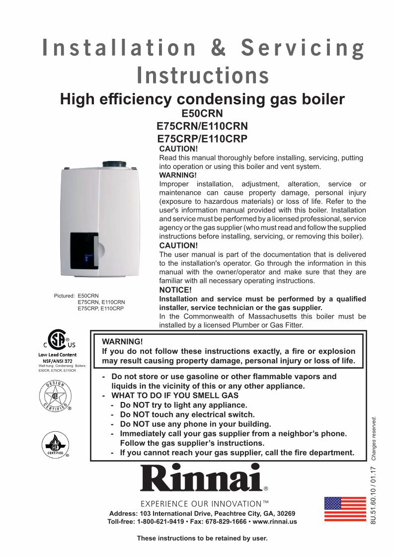
High effi ciency condensing gas boilerE50CRN
E75CRN/E110CRNE75CRP/E110CRP
- Do not store or use gasoline or other fl ammable vapors and liquids in the vicinity of this or any other appliance.
- WHAT TO DO IF YOU SMELL GAS- Do NOT try to light any appliance.- Do NOT touch any electrical switch. - Do NOT use any phone in your building.- Immediately call your gas supplier from a neighbor’s phone.
Follow the gas supplier’s instructions.- If you cannot reach your gas supplier, call the fi re department.
CAUTION!Read this manual thoroughly before installing, servicing, putting into operation or using this boiler and vent system.WARNING!Improper installation, adjustment, alteration, service or maintenance can cause property damage, personal injury (exposure to hazardous materials) or loss of life. Refer to the user's information manual provided with this boiler. Installation and service must be performed by a licensed professional, service agency or the gas supplier (who must read and follow the supplied instructions before installing, servicing, or removing this boiler).CAUTION!The user manual is part of the documentation that is delivered to the installation's operator. Go through the information in this manual with the owner/operator and make sure that they are familiar with all necessary operating instructions.NOTICE!Installation and service must be performed by a qualifi ed installer, service technician or the gas supplier. In the Commonwealth of Massachusetts this boiler must be installed by a licensed Plumber or Gas Fitter.
WARNING!If you do not follow these instructions exactly, a fi re or explosion may result causing property damage, personal injury or loss of life.
These instructions to be retained by user.
Address: 103 International Drive, Peachtree City, GA, 30269Toll-free: 1-800-621-9419 • Fax: 678-829-1666 • www.rinnai.us
Pictured: E50CRN E75CRN, E110CRN E75CRP, E110CRP
Wall-hung Condensing Boilers: E50CR, E75CR, E110CR
Inst
alla
tion
& Se
rvic
ing
Inst
ruct
ions
Rin
nai E
-Ser
ies
2
Contents of instructionsThese installation instructions contain important information for the safe installation, start-up and maintenance of boilers with capacities 50,000 through 110,000 BTU/hr.These installation instructions are intended for licensed professionals, who have the necessary knowledge and are approved for working on heating and gas systems.
Subject to technical changesChanges may be made without notice to the illustrations, process steps and technical data as a result of our policy of continuous improvement.
Updating of documentationPlease contact us if you have any suggestions for improvements or corrections.
California Proposition 65 lists chemical substances known to the state to cause cancer, birth defects, death,serious illness or other reproductive harm. This product may contain such substances, be their origin from fuelcombustion (gas, oil) or components of the product itself.
Inst
alla
tion
& Se
rvic
ing
Inst
ruct
ions
Rin
nai E
-Ser
ies
3
Content
1 Safety and general instructions ........................................................4 1.1 Designated use ...................................................................4 1.2 Hazard defi nitions ................................................................4 1.3 Symbol defi nitions ...............................................................4 1.4 The following instructions must be followed ........................5 1.5 Follow these instructions for the space heating water .........6 1.6 Tools, materials and additional equipment ..........................6 1.7 Relevant Installation, Service and User manuals ................7 1.8 Disposal ...........................................................................72 Regulations and guidelines ..............................................................73 Description of the boiler ...................................................................84 Packaging and transportation ..........................................................9 4.1 Scope of delivery .................................................................9 4.2 Transportation .....................................................................95 Installation .........................................................................10 5.1 Requirements for the installation room .............................10 5.2 Fitting the boiler .................................................................11 5.3 Dimensions ........................................................................12 5.3.1 Clearances from boiler ......................................................13 5.4 Technical specifi cations .....................................................146 Connecting the boiler .....................................................................15 6.1 Central heating system ......................................................15 6.1.3 Safety valve .......................................................................20 6.1.4 Low water cut off ...............................................................20 6.2 Boiler expansion tank ........................................................20 6.3 Underfl oor heating system (plastic pipes) ...........................20 6.4 Gas supply connection ......................................................20 6.4.1 Gas connection with natural gas .......................................21 6.5 Hot water supply ................................................................22 6.5.1 Domestic Water quality ......................................................22 6.5.2 Domestic water treatment Accessory ...............................22 6.5.3 DHW Expansion Tank ........................................................23 6.5.4 Installing a Thermostatic Mixing Valve .............................23 6.5.5 Installing a valve kit ...........................................................24 6.5.6 Pressure relief Valve ..........................................................24 6.5.7 Programming domestic hot water preheat ........................24 6.6 Condensate drain pipe ......................................................25 6.7 Vent system and air supply system ...................................26 6.7.1 Intake / Exhaust Guidelines ...............................................26 6.7.2a Examples vent and air supply systems (parallel) ..............27 6.7.2b Examples vent and air supply systems (low profi le PP) ....28 6.7.3 Installation of the vent system ...........................................29 6.7.3.1 Conversion from parallel to concentric vent system ..........30 6.7.3.2 Installing air fi lter ...............................................................30 6.7.4 Vent/air intake terminal position ........................................31 6.7.5 Direct vent closet and alcove installation ........................33 6.7.6 Dimensioning of the exhaust and air intake duct .............34 6.7.7 Combustion air and vent piping lengths. ...........................35 6.7.8 Calculation of compensation factor ...................................36 6.7.9 Room Air System (indoor combustion air) .........................37
7 Electrical connections ....................................................................408 Boiler controls .........................................................................44 8.1 Explanation of the function buttons ...................................459 Starting up: Filling and de-aerating the boiler and installation .......46 9.1 Requirements of the water system ....................................46 9.2 Filling the heating system ..................................................47 9.3 Hot water supply ................................................................4810 Adjustments .........................................................................50 10.1 Altering adjustments ..........................................................50 10.2 Activating factory settings (green button function) ...........5311 Isolating the boiler .........................................................................5312 Commissioning .........................................................................54 12.1 Testing for gas leaks ..........................................................55 12.2 Testing the Ignition Safety shut off device .........................55 12.3 Checking the O2.................................................................56 12.4 Measuring the ionization current .......................................59 12.5 Installing the casing ...........................................................5713 Maintenance .........................................................................58 13.1 Periodic examination of venting systems and boiler .........58 13.2 Inspection .........................................................................58 13.2.1 Visual inspection for general signs of corrosion ................59 13.2.2 Measuring the ionization current .......................................59 13.2.3 Measuring the inlet gas pressure ......................................59 13.2.4 Testing for gas leaks ..........................................................59 13.2.5 Carrying out a pressure test of the heating system ...........59 13.2.6 Checking venting systems .................................................59 13.3 Maintenance activities .......................................................60 13.3.1 Reset service interval counter ...........................................63 13.4 Limited warranty ................................................................6314 Parts of the boiler .........................................................................6415 Blocks and Errors .........................................................................65 15.1 Error indication (short reference) .......................................65 15.2 Blocks .........................................................................66 15.3 Errors .........................................................................67 15.4 Other Errors .......................................................................7216 Spare parts .........................................................................8417 Parts list vent system .....................................................................8018 Common venting guidelines ...........................................................82
Appendix A - Outoor Reset Sensor Data and Resistance table NTC sensors .......................................83
Inst
alla
tion
& Se
rvic
ing
Inst
ruct
ions
Rin
nai E
-Ser
ies
4
1 Safety and general instructions
Please observe these instructions in the interest of your own safety.
1.1 Designated use
The boiler is designed for heating water for a central heating system and generating domestic hot water. The boiler is delivered with a burner controller (MCBA) pre-installed.The boiler can be fi tted with a outdoor reset sensor (included with the boiler) or an On/Off thermostat or relay panel end switch (fi eld supplied accessories).
1.2 Hazard defi nitions
The following defi ned terms are used throughout the documentation to bring attention to the presence of hazards of various risk levels. Notices give important information concerning the operation of the product.
DANGER:Indicates the presence of hazards that will cause severe personal injury, death or substantial property damage.
WARNING:Indicates the presence of hazards that can cause severe personal injury, death or substantial property damage.
CAUTION:Indicates presence of hazards that will or can cause minor personal injury or property damage.
CAUTION:Risk of electric shock. Indicates presence of hazards due to electric shock.
NOTICE:Indicates special instructions on installation, operation or maintenance that are important but not related to personal injury or property damage.
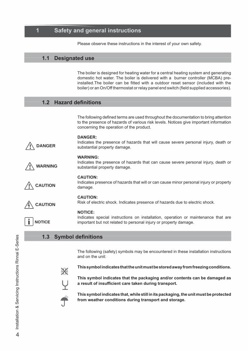
1.3 Symbol defi nitions
The following (safety) symbols may be encountered in these installation instructions and on the unit:
This symbol indicates that the unit must be stored away from freezing conditions.
This symbol indicates that the packaging and/or contents can be damaged as a result of insuffi cient care taken during transport.
This symbol indicates that, while still in its packaging, the unit must be protected from weather conditions during transport and storage.
! CAUTION
CAUTION
NOTICEi
! DANGER
! WARNING
Inst
alla
tion
& Se
rvic
ing
Inst
ruct
ions
Rin
nai E
-Ser
ies
5
1.4 The following instructions must be followed
- The boiler must only be used for its designated purpose, as described in the Installation Instructions.
- Each unit is fi tted with a data plate. Consult the details on this plate to verify whether the boiler is compliant with its intended location, e.g.: gas type, power source and venting classifi cation.
- Only use the boiler with the accessories and spare parts listed.- Other accessories and consumables may only be used if they are specifi cally
designed for the intended application and do not aff ect the system performance and the safety requirements.
- Maintenance and repairs must be performed by licensed professionals.- Gas utility/supplier may require reporting and/or approval of condensing gas boiler
installations.- You are only allowed to operate the condensing gas boiler with the vent system
that has been specifi cally designed and approved for this type of boiler.- Local codes governing the vent system and condensate water disposal must be
followed.You must also respect:- The local building codes stipulating the installation rules.- The local building codes concerning the air intake and outlet systems and the
chimney connection.- The regulations for the power supply connection.- The technical rules established by the gas utility company concerning the
connection to the local gas mains.- The instructions and standards concerning the safety equipment for the water/
space heating system.- The Installation Instructions for building heating systems.- The boiler must be located in an area where leakage of the boiler or connections
will not result in damage to the area adjacent to the boiler or to lower fl oors of the structure. When such locations cannot be avoided, it is recommended that a suitable drain pan be installed under the boiler.
- The boiler must be installed in such way that the all components are protected from water (dripping, spraying, rain etc.) during boiler operation and service.
- The boiler must not be installed on or against carpeting.- Do not restrict or seal any air intake or outlet openings.- If you fi nd any defects, you must inform the owner of the system of the defect and
the associated hazard in writing.
Failure to properly commission the boiler as described in section 13 may result in unreliable burner operation, reduced component life, and unsafe boiler operation and may void the product warranty.
DANGER. Gas is fl ammable and may cause an explosion. Beware if you smell gas: there may be an explosion hazard!
If the information in these instructions is not followed exactly, a fi re or explosion may result causing property damage, personal injury or death.- Do not store or use gasoline or other fl ammable vapors and liquids in the vicinity
of this or any other appliance.WHAT TO DO IF YOU SMELL GAS- Do NOT try to light any appliance.- Do NOT touch any electrical switch. - Do NOT use any phone in your building.- Immediately call your gas supplier from a neighbor’s phone. Follow the gas
supplier’s instructions.- If you cannot reach your gas supllier, call the fi re department.
Should overheating occur or the gas supply fail to shut off , do not turn off or disconnect the electrical supply to the pump. Instead, shut off the gas supply at a location external to the appliance.
! DANGER
! WARNING
! WARNING
! WARNING
Inst
alla
tion
& Se
rvic
ing
Inst
ruct
ions
Rin
nai E
-Ser
ies
6
Chemicals that are corrosive in nature should not be stored or used near the boiler or vent termination.
1.5 Boiler System Water Requirements
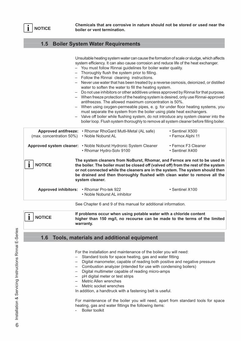
Unsuitable heating system water can cause the formation of scale or sludge, which aff ects system effi ciency. It can also cause corrosion and reduce life of the heat exchanger. – You must follow Rinnai guidelines for boiler water quality.– Thoroughly fl ush the system prior to fi lling.– Follow the Rinnai cleaning instructions.– Never use water that has been treated by a reverse osmosis, deionized, or distilled
water to soften the water to fi ll the heating system.– Do not use inhibitors or other additives unless approved by Rinnai for that purpose.– When freeze protection of the heating system is desired, only use Rinnai-approved
antifreezes. The allowed maximum concentration is 50%.– When using oxygen-permeable pipes, e. g. for under fl oor heating systems, you
must separate the system from the boiler using plate heat exchangers. – Valve off boiler while fl ushing system, do not introduce any system cleaner into the
boiler loop. Flush system thoroughly to remove all system cleaner before fi lling boiler.
Approved antifreeze: • Rhomar RhoGard Mutli-Metal (AL safe) • Sentinel X500 (max. concentration 50%) • Noble Noburst AL • Fernox Alphi 11
Approved system cleaner: • Noble Noburst Hydronic System Cleaner • Fernox F3 Cleaner • Rhomar Hydro-Solv 9100 • Sentinel X400
The system cleaners from NoBurst, Rhomar, and Fernox are not to be used in the boiler. The boiler must be closed off (valved off ) from the rest of the system or not connected while the cleaners are in the system. The system should then be drained and then thoroughly fl ushed with clean water to remove all the system cleaner.
Approved inhibitors: • Rhomar Pro-tek 922 • Sentinel X100 • Noble Noburst AL inhibitor
See Chapter 6 and 9 of this manual for additional information.
If problems occur when using potable water with a chloride contenthigher than 150 mg/l, no recourse can be made to the terms of the limited warranty.
1.6 Tools, materials and additional equipment
For the installation and maintenance of the boiler you will need:– Standard tools for space heating, gas and water fi tting– Digital manometer, capable of reading both positive and negative pressure– Combustion analyzer (intended for use with condensing boilers)– Digital multimeter capable of reading micro-amps– pH digital meter or test strips– Metric Allen wrenches– Metric socket wrenchesIn addition, a handtruck with a fastening belt is useful.
For maintenance of the boiler you will need, apart from standard tools for space heating, gas and water fi ttings the following items:- Boiler toolkit
NOTICEi
NOTICEi
NOTICEi
Inst
alla
tion
& Se
rvic
ing
Inst
ruct
ions
Rin
nai E
-Ser
ies
7
1.7 Relevant Installation, Service and User manuals
– Approved vent system– User manual
1.8 Disposal
– Dispose of the boiler packaging in an environmentally sound manner.– Dispose of components of the heating system (e.g. boiler or control device), that
must be replaced in an environmentally responsible manner.
2 Regulations and guidelines
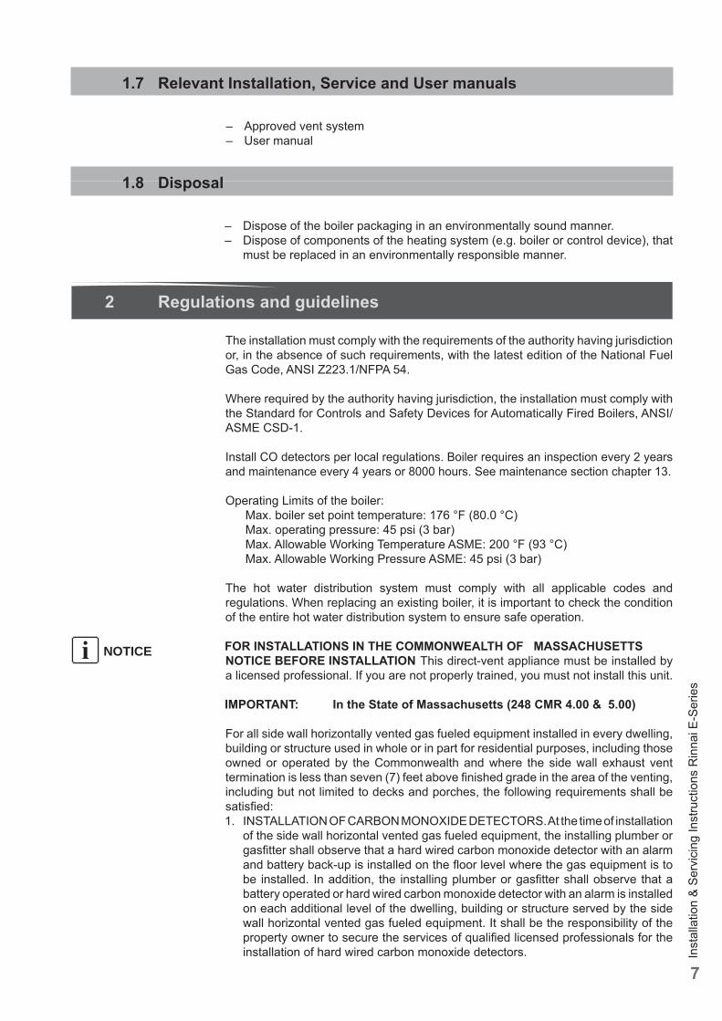
The installation must comply with the requirements of the authority having jurisdiction or, in the absence of such requirements, with the latest edition of the National Fuel Gas Code, ANSI Z223.1/NFPA 54.
Where required by the authority having jurisdiction, the installation must comply with the Standard for Controls and Safety Devices for Automatically Fired Boilers, ANSI/ASME CSD-1.
Install CO detectors per local regulations. Boiler requires an inspection every 2 years and maintenance every 4 years or 8000 hours. See maintenance section chapter 13.
Operating Limits of the boiler: Max. boiler set point temperature: 176 °F (80.0 °C) Max. operating pressure: 45 psi (3 bar) Max. Allowable Working Temperature ASME: 200 °F (93 °C) Max. Allowable Working Pressure ASME: 45 psi (3 bar)
The hot water distribution system must comply with all applicable codes and regulations. When replacing an existing boiler, it is important to check the condition of the entire hot water distribution system to ensure safe operation.
FOR INSTALLATIONS IN THE COMMONWEALTH OF MASSACHUSETTSNOTICE BEFORE INSTALLATION This direct-vent appliance must be installed by a licensed professional. If you are not properly trained, you must not install this unit.
IMPORTANT: In the State of Massachusetts (248 CMR 4.00 & 5.00)
For all side wall horizontally vented gas fueled equipment installed in every dwelling, building or structure used in whole or in part for residential purposes, including those owned or operated by the Commonwealth and where the side wall exhaust vent termination is less than seven (7) feet above fi nished grade in the area of the venting, including but not limited to decks and porches, the following requirements shall be satisfi ed:1. INSTALLATION OF CARBON MONOXIDE DETECTORS. At the time of installation
of the side wall horizontal vented gas fueled equipment, the installing plumber or gasfi tter shall observe that a hard wired carbon monoxide detector with an alarm and battery back-up is installed on the fl oor level where the gas equipment is to be installed. In addition, the installing plumber or gasfi tter shall observe that a battery operated or hard wired carbon monoxide detector with an alarm is installed on each additional level of the dwelling, building or structure served by the side wall horizontal vented gas fueled equipment. It shall be the responsibility of the property owner to secure the services of qualifi ed licensed professionals for the installation of hard wired carbon monoxide detectors.
NOTICEi
Inst
alla
tion
& Se
rvic
ing
Inst
ruct
ions
Rin
nai E
-Ser
ies
8
a. In the event that the side wall horizontally vented gas fueled equipment is installed in a crawl space or an attic, the hard wired carbon monoxide detector with alarm and battery back-up may be installed on the next adjacent fl oor level.
b. In the event that the requirements of this subdivision can not be met at the time of completion of installation, the owner shall have a period of thirty (30} days to comply with the above requirements; provided, however, that during said thirty (30} day period, a battery operated carbon monoxide detector with an alarm shall be installed.
2. APPROVED CARBON MONOXIDE DETECTORS. Each carbon monoxide detector as required in accordance with the above provisions shall comply with NFPA 720 and be ANSI/UL 2034 listed and IAS certifi ed.
3 Description of the boiler
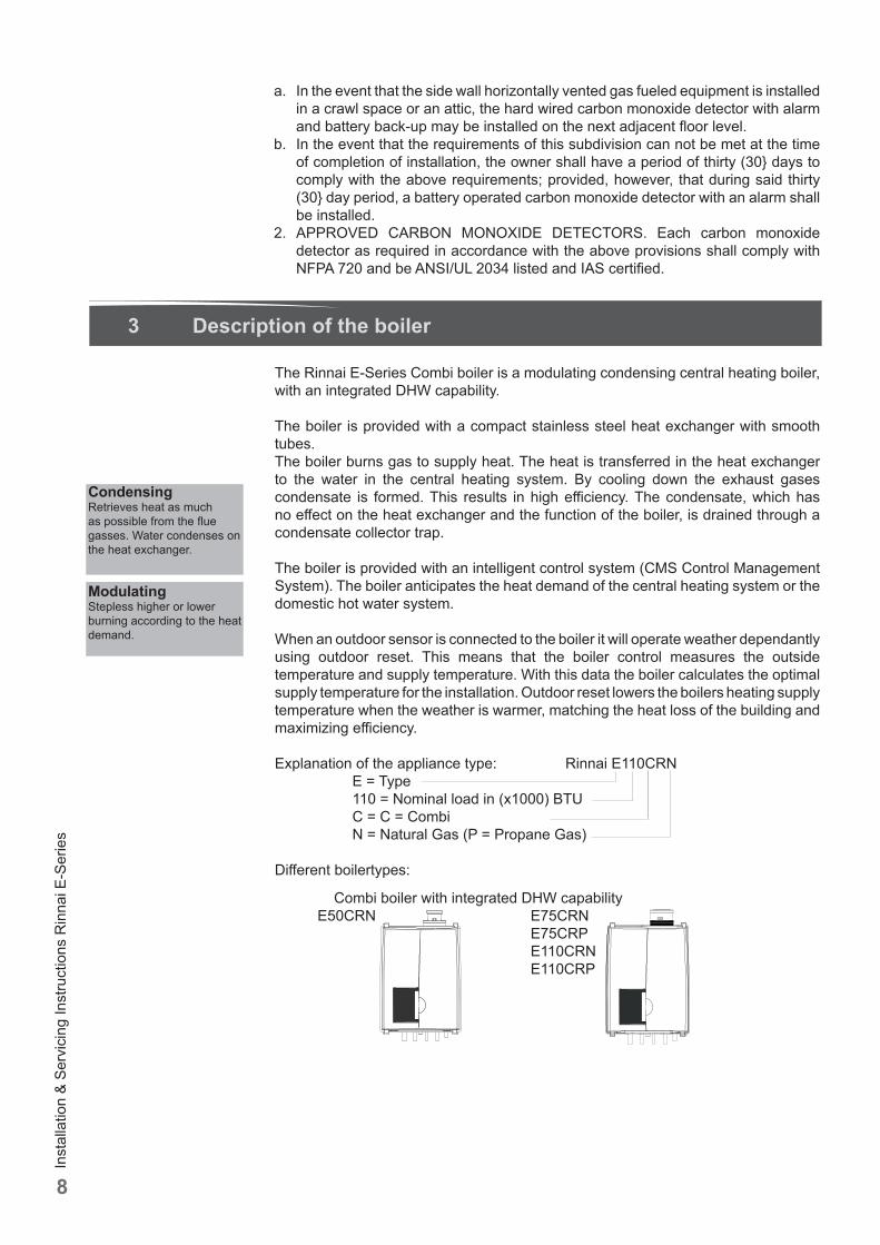
The Rinnai E-Series Combi boiler is a modulating condensing central heating boiler, with an integrated DHW capability.
The boiler is provided with a compact stainless steel heat exchanger with smooth tubes.The boiler burns gas to supply heat. The heat is transferred in the heat exchanger to the water in the central heating system. By cooling down the exhaust gases condensate is formed. This results in high effi ciency. The condensate, which has no eff ect on the heat exchanger and the function of the boiler, is drained through a condensate collector trap.
The boiler is provided with an intelligent control system (CMS Control Management System). The boiler anticipates the heat demand of the central heating system or the domestic hot water system.
When an outdoor sensor is connected to the boiler it will operate weather dependantly using outdoor reset. This means that the boiler control measures the outside temperature and supply temperature. With this data the boiler calculates the optimal supply temperature for the installation. Outdoor reset lowers the boilers heating supply temperature when the weather is warmer, matching the heat loss of the building and maximizing effi ciency.
Explanation of the appliance type: Rinnai E110CRN E = Type 110 = Nominal load in (x1000) BTU C = C = Combi N = Natural Gas (P = Propane Gas)
Diff erent boilertypes:
CondensingRetrieves heat as much as possible from the fl ue gasses. Water condenses on the heat exchanger.
ModulatingStepless higher or lower burning according to the heat demand.
Combi boiler with integrated DHW capability E50CRN E75CRN E75CRP E110CRN E110CRP
Inst
alla
tion
& Se
rvic
ing
Inst
ruct
ions
Rin
nai E
-Ser
ies
9
4 Packaging and transportation
4.1 Scope of delivery
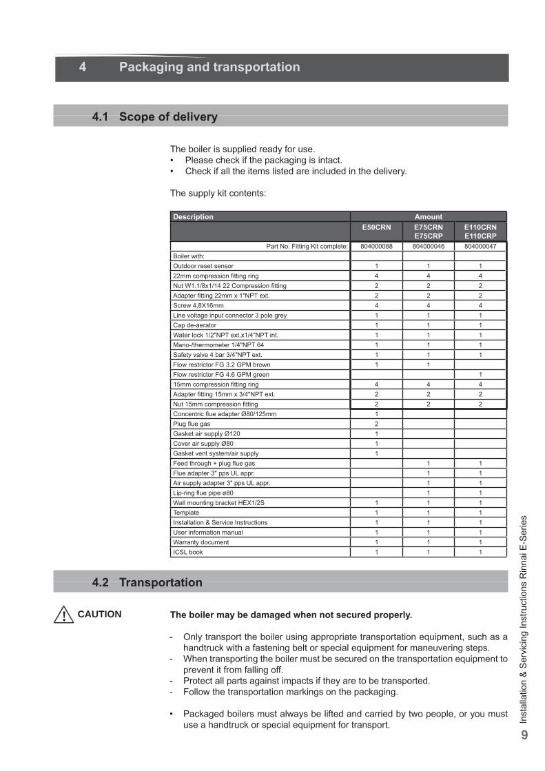
The boiler is supplied ready for use.• Please check if the packaging is intact.• Check if all the items listed are included in the delivery.
The supply kit contents:
Description AmountE50CRN E75CRN
E75CRPE110CRNE110CRP
Part No. Fitting Kit complete: 804000088 804000046 804000047Boiler with:Outdoor reset sensor 1 1 122mm compression fi tting ring 4 4 4Nut W1.1/8x1/14 22 Compression fi tting 2 2 2Adapter fi tting 22mm x 1"NPT ext. 2 2 2Screw 4,8X16mm 4 4 4Line voltage input connector 3 pole grey 1 1 1Cap de-aerator 1 1 1Water lock 1/2"NPT ext.x1/4"NPT int. 1 1 1Mano-/thermometer 1/4"NPT 64 1 1 1Safety valve 4 bar 3/4"NPT ext. 1 1 1Flow restrictor FG 3.2 GPM brown 1 1Flow restrictor FG 4.6 GPM green 115mm compression fi tting ring 4 4 4Adapter fi tting 15mm x 3/4"NPT ext. 2 2 2Nut 15mm compression fi tting 2 2 2Concentric fl ue adapter Ø80/125mm 1Plug fl ue gas 2Gasket air supply Ø120 1Cover air supply Ø80 1Gasket vent system/air supply 1Feed through + plug fl ue gas 1 1Flue adapter 3" pps UL appr. 1 1Air supply adapter 3" pps UL appr. 1 1Lip-ring fl ue pipe ø80 1 1Wall mounting bracket HEX1/2S 1 1 1Template 1 1 1Installation & Service Instructions 1 1 1User information manual 1 1 1Warranty document 1 1 1ICSL book 1 1 1
4.2 Transportation
The boiler may be damaged when not secured properly.
- Only transport the boiler using appropriate transportation equipment, such as a handtruck with a fastening belt or special equipment for maneuvering steps.
- When transporting the boiler must be secured on the transportation equipment to prevent it from falling off .
- Protect all parts against impacts if they are to be transported.- Follow the transportation markings on the packaging.
• Packaged boilers must always be lifted and carried by two people, or you must use a handtruck or special equipment for transport.
! CAUTION
Inst
alla
tion
& Se
rvic
ing
Inst
ruct
ions
Rin
nai E
-Ser
ies
10
5 Installation
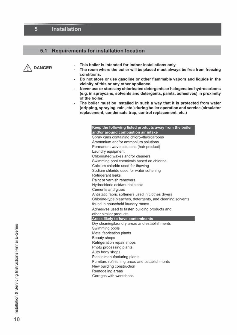
5.1 Requirements for installation location
- This boiler is intended for indoor installations only.- The room where the boiler will be placed must always be free from freezing
conditions.- Do not store or use gasoline or other fl ammable vapors and liquids in the
vicinity of this or any other appliance.- Never use or store any chlorinated detergents or halogenated hydrocarbons
(e.g. in spraycans, solvents and detergents, paints, adhesives) in proximity of the boiler.
- The boiler must be installed in such a way that it is protected from water (dripping, spraying, rain, etc.) during boiler operation and service (circulator replacement, condensate trap, control replacement, etc.)
! DANGER
Inst
alla
tion
& Se
rvic
ing
Inst
ruct
ions
Rin
nai E
-Ser
ies
11
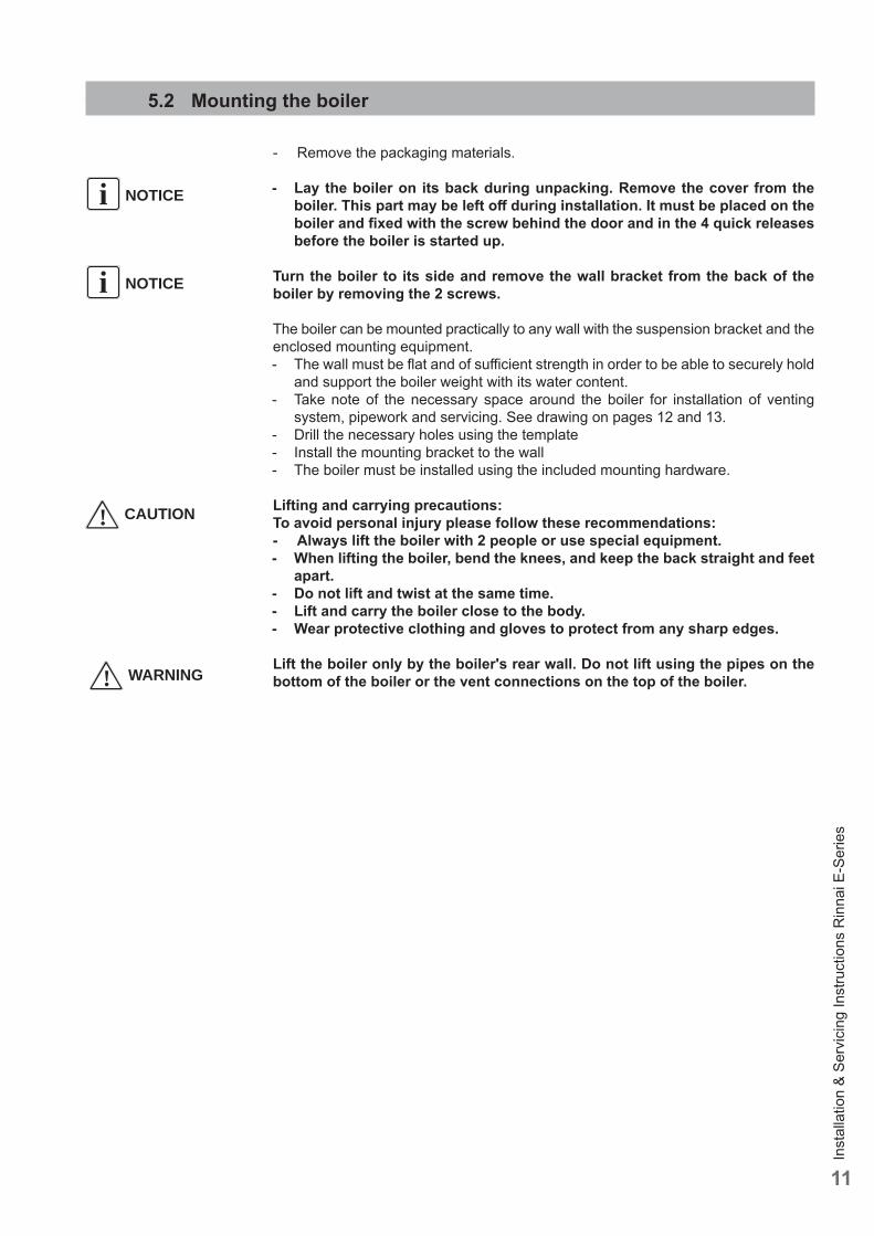
5.2 Mounting the boiler
- Remove the packaging materials.
- Lay the boiler on its back during unpacking. Remove the cover from the boiler. This part may be left off during installation. It must be placed on the boiler and fi xed with the screw behind the door and in the 4 quick releases before the boiler is started up.
Turn the boiler to its side and remove the wall bracket from the back of the boiler by removing the 2 screws.
The boiler can be mounted practically to any wall with the suspension bracket and the enclosed mounting equipment. - The wall must be fl at and of suffi cient strength in order to be able to securely hold
and support the boiler weight with its water content.- Take note of the necessary space around the boiler for installation of venting
system, pipework and servicing. See drawing on pages 12 and 13.- Drill the necessary holes using the template- Install the mounting bracket to the wall- The boiler must be installed using the included mounting hardware.
Lifting and carrying precautions:To avoid personal injury please follow these recommendations:- Always lift the boiler with 2 people or use special equipment.- When lifting the boiler, bend the knees, and keep the back straight and feet
apart.- Do not lift and twist at the same time.- Lift and carry the boiler close to the body.- Wear protective clothing and gloves to protect from any sharp edges.
Lift the boiler only by the boiler's rear wall. Do not lift using the pipes on the bottom of the boiler or the vent connections on the top of the boiler.
! CAUTION
NOTICEi
NOTICEi
! WARNING
Inst
alla
tion
& Se
rvic
ing
Inst
ruct
ions
Rin
nai E
-Ser
ies
12
CF
A
B
D
H
JK
G
P
U
E
O
Q R
T
N
f w g k r c
V
CF
A
B
D
H
JK
G
P
T
E
O
Q R
T
N
f w g k r c
V
E50CRN E75CRNE75CRPE110CRN E110CRP
S
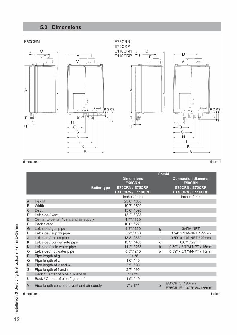
5.3 Dimensions
dimensions table 1
dimensions fi gure 1
S
Inst
alla
tion
& Se
rvic
ing
Inst
ruct
ions
Rin
nai E
-Ser
ies
13
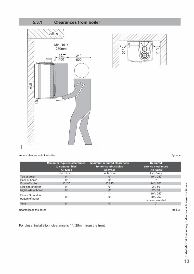
clearances to the boiler table 3
service clearances to the boiler fi gure 4
wal
lceiling
For closet installation: clearance is 1” / 25mm from the front.
2"50
Min. 10" / 250mm
15.7"400
24"600
5.3.1 Clearances from boiler
Minimum required clearances to combustibles
Minimum required clearances to non-combustibles
Requiredservice clearances
All types All types All typesinch / mm inch / mm inch / mm
Top of boiler 0" 0" 10" / 250Back of boiler 0" 0" 0"Front of boiler 1" / 25 1" / 25 24" / 600Left side of boiler 0" 0" 2" / 50Right side of boiler 0" 0" 2" / 50
Floor / Ground to bottom of boiler 0" 0"
10" / 25030" / 762
is recommendedVent 0" 0" 0"
2"50
Inst
alla
tion
& Se
rvic
ing
Inst
ruct
ions
Rin
nai E
-Ser
ies
14
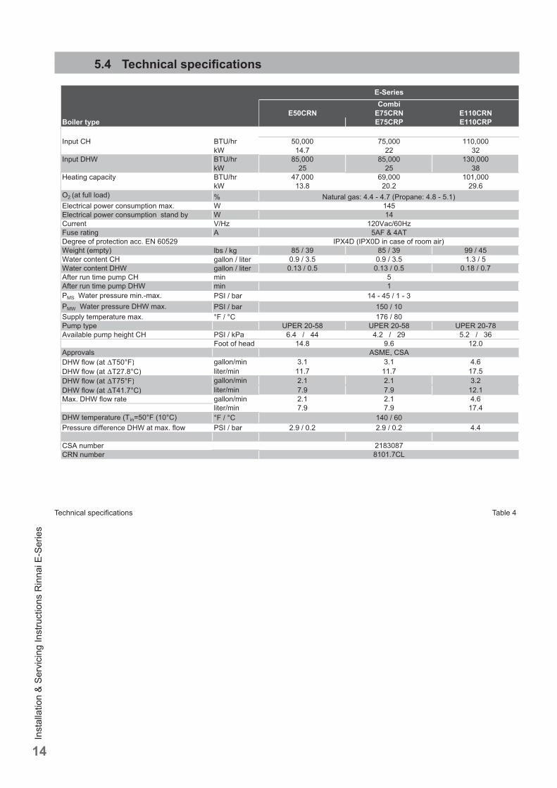
5.4 Technical specifi cations
Technical specifi cations Table 4
Inst
alla
tion
& Se
rvic
ing
Inst
ruct
ions
Rin
nai E
-Ser
ies
15
6 Connecting the boiler
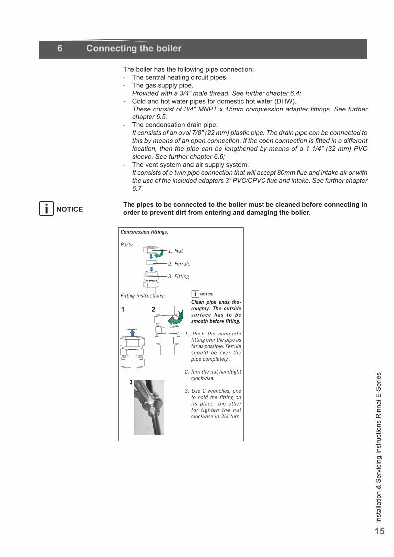
The boiler has the following pipe connection;- The central heating circuit pipes.- The gas supply pipe. Provided with a 3/4" male thread. See further chapter 6.4;- Cold and hot water pipes for domestic hot water (DHW). These consist of 3/4" MNPT x 15mm compression adapter fi ttings. See further
chapter 6.5;- The condensation drain pipe. It consists of an oval 7/8" (22 mm) plastic pipe. The drain pipe can be connected to
this by means of an open connection. If the open connection is fi tted in a diff erent location, then the pipe can be lengthened by means of a 1 1/4" (32 mm) PVC sleeve. See further chapter 6.6;
- The vent system and air supply system. It consists of a twin pipe connection that will accept 80mm fl ue and intake air or with
the use of the included adapters 3” PVC/CPVC fl ue and intake. See further chapter 6.7.
The pipes to be connected to the boiler must be cleaned before connecting in order to prevent dirt from entering and damaging the boiler.NOTICEi
Compression fittings.
Parts: 1. Nut
2. Ferrule
3. Fitting
Fitting instructions: Clean pipe ends tho-
roughly. The outside sur face has to be smooth before fitting.
1. Push the complete fitting over the pipe as far as possible. Ferrule should be over the pipe completely.
2. Turn the nut handtight clockwise.
3. Use 2 wrenches, one to hold the fitting on its place, the other for tighten the nut clockwise in 3/4 turn.
21
3
NOTICEi
Inst
alla
tion
& Se
rvic
ing
Inst
ruct
ions
Rin
nai E
-Ser
ies
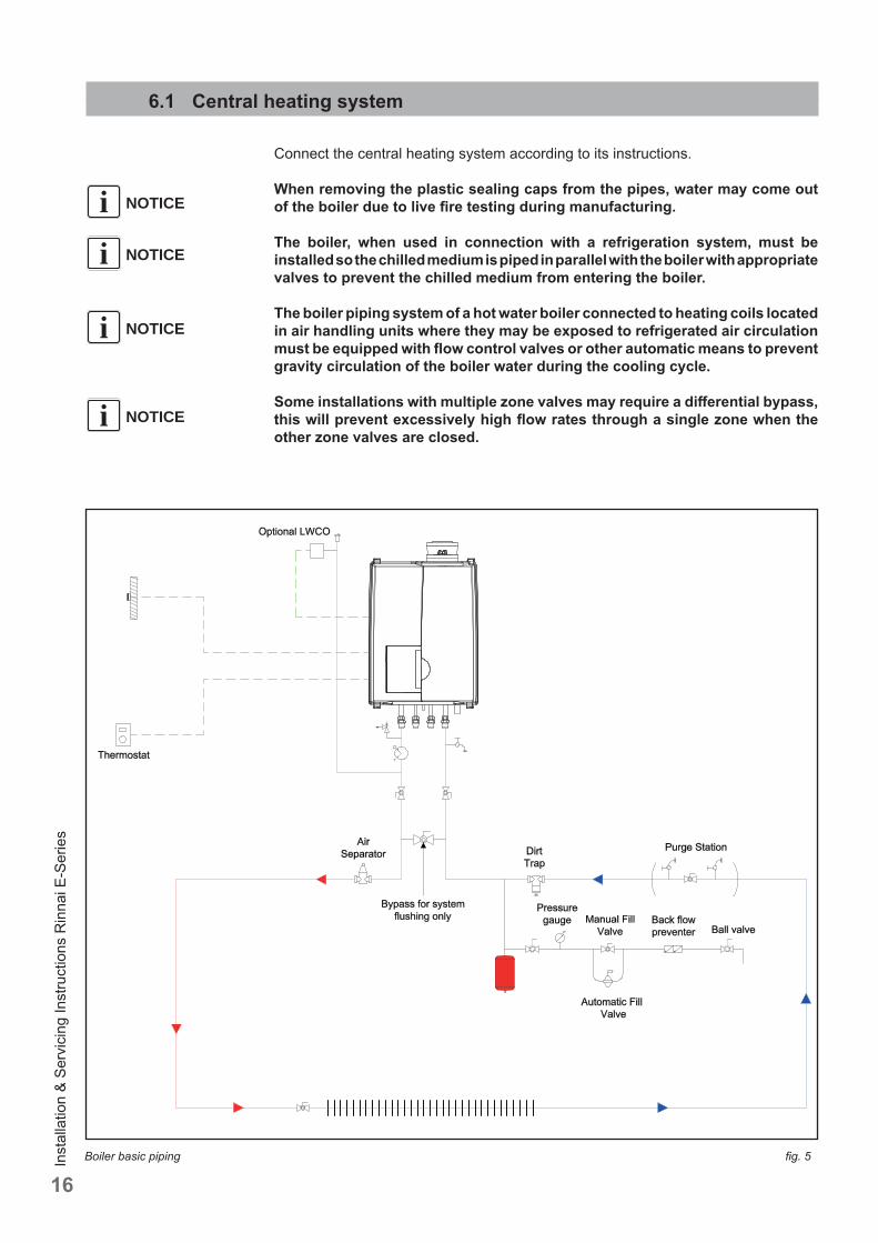
16Boiler basic piping fi g. 5
6.1 Central heating system
Connect the central heating system according to its instructions.
When removing the plastic sealing caps from the pipes, water may come out of the boiler due to live fi re testing during manufacturing.
The boiler, when used in connection with a refrigeration system, must be installed so the chilled medium is piped in parallel with the boiler with appropriate valves to prevent the chilled medium from entering the boiler.
The boiler piping system of a hot water boiler connected to heating coils located in air handling units where they may be exposed to refrigerated air circulation must be equipped with fl ow control valves or other automatic means to prevent gravity circulation of the boiler water during the cooling cycle.
Some installations with multiple zone valves may require a diff erential bypass, this will prevent excessively high fl ow rates through a single zone when the other zone valves are closed.
NOTICEi
NOTICEi
NOTICEi
NOTICEi
Inst
alla
tion
& Se
rvic
ing
Inst
ruct
ions
Rin
nai E
-Ser
ies
17
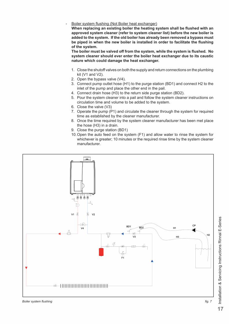
- Boiler system fl ushing (Not Boiler heat exchanger)When replacing an existing boiler the heating system shall be fl ushed with an approved system cleaner (refer to system cleaner list) before the new boiler is added to the system. If the old boiler has already been removed a bypass must be piped in when the new boiler is installed in order to facilitate the fl ushing of the system. The boiler must be valved off from the system, while the system is fl ushed. No system cleaner should ever enter the boiler heat exchanger due to its caustic nature which could damage the heat exchanger.
1. Close the shutoff valves on both the supply and return connections on the plumbing kit (V1 and V2).
2. Open the bypass valve (V4).3. Connect pump outlet hose (H1) to the purge station (BD1) and connect H2 to the
inlet of the pump and place the other end in the pail.4. Connect drain hose (H3) to the return side purge station (BD2).5. Pour the system cleaner into a pail and follow the system cleaner instructions on
circulation time and volume to be added to the system.6. Close the valve (V3)7. Operate the pump (P1) and circulate the cleaner through the system for required
time as established by the cleaner manufacturer.8. Once the time required by the system cleaner manufacturer has been met place
the hose (H3) in a drain.9. Close the purge station (BD1) 10. Open the auto feed on the system (F1) and allow water to rinse the system for
whichever is greater; 10 minutes or the required rinse time by the system cleaner manufacturer.
Boiler system fl ushing fi g. 7
Inst
alla
tion
& Se
rvic
ing
Inst
ruct
ions
Rin
nai E
-Ser
ies
18
11. If the installation is a zone system be sure to purge out each zone individually12. Close the auto feed on the system (F1)13. Close the return side purge station (BD2) and disconnect the hose (H3).14. Open the main valve on the system return (V3)15. Close the bypass valve below the boiler (V4).16. Open shutoff valves on both the supply and return connections below the boiler
(V1 and V2).17. Clean out the dirt trap18. Test the pH of the water that will be used for fi lling the system19. Test the water hardness of the water that will be used for fi lling the system20. Use the proper water treatment to ensure the pH and water hardness are within
the Rinnai boiler water quality guidelines21. The boiler and system may now be fi lled.
The following is a list of approved system cleaners, inhibitors, and antifreeze.
Approved antifreeze: • Rhomar RhoGard Mutli-Metal (AL safe) • Sentinel X500 • Noble Noburst AL • Fernox Alphi 11
Approved system cleaner: • Noble Noburst Hydronic System Cleaner • Fernox F3 Cleaner • Rhomar Hydro-Solv 9100 • Sentinel X400
The system cleaners from NoBurst, Rhomar, and Fernox are NOT to be used in the boiler. The boiler must be closed off (valved off ) from the rest of the system or not connected while the cleaners are in the system. The system should then be drained and then thoroughly fl ushed with clean water to remove all the system cleaner.
Approved inhibitors: • Rhomar Pro-tek 922 • Sentinel X100 • Noble Noburst AL inhibitor
- Connect the expansion tank to the system. See chapter 6.2.- Connect the pipes so that they are free from strain.
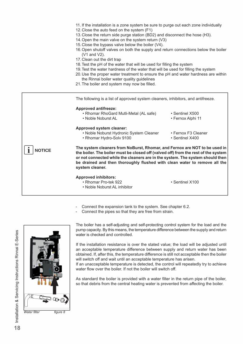
The boiler has a self-adjusting and self-protecting control system for the load and the pump capacity. By this means, the temperature diff erence between the supply and return water is checked and controlled.
If the installation resistance is over the stated value; the load will be adjusted until an acceptable temperature diff erence between supply and return water has been obtained. If, after this, the temperature diff erence is still not acceptable then the boiler will switch off and wait until an acceptable temperature has arisen.If an unacceptable temperature is detected, the control will repeatedly try to achieve water fl ow over the boiler. If not the boiler will switch off .
As standard the boiler is provided with a water fi lter in the return pipe of the boiler, so that debris from the central heating water is prevented from aff ecting the boiler.
NOTICEi
Water fi lter fi gure 8
Inst
alla
tion
& Se
rvic
ing
Inst
ruct
ions
Rin
nai E
-Ser
ies
19
To protect the entire heating system we recommend installing a dirt particle trap in the return circuit. When the boiler is installed to an existing heating system this trap is required. Use of a Y strainer is not permitted as substitute for a dirt trap.
- Position H3 (fi gure 7) is a garden hose thread boiler drain, that can be used to drain the boiler or add water treatment additives to the system, such as inhibitors or glycol.
- For information on locating the expansion tank and system fi ll, please see the Rinnai Boiler Applications Manual.
The boiler is designed to be used on pressurized heating systems only (closed loop).
If the boiler is to be installed in a system that utilizes zone pumps and not zone valves a low loss header plumbing kit should also be installed (part number: 804000061).
If the pressure drop in the loop/system is greater than the available head pressure from the boiler pump a low loss header plumbing kit should be used (part number: 804000061).
NOTICEi
NOTICEi
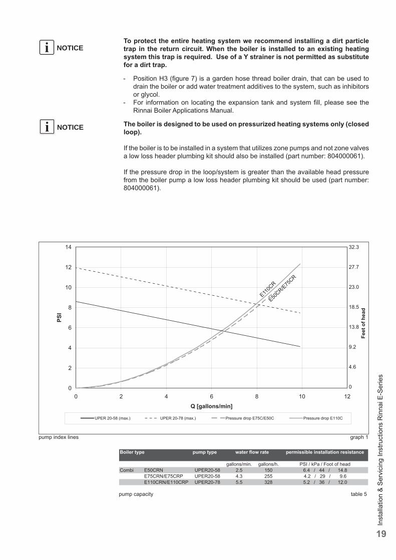
pump index lines graph 1
0
2
4
6
8
10
12
14
0 2 4 6 8 10 12Q [gallons/min]
PSI
UPER 20-58 (max.) UPER 20-78 (max.) Pressure drop E75C/E50C Pressure drop E110C
32.3
27.7
23.0
18.5
13.8
9.2
4.6
0
Feet
of h
ead
E50CR/E75
CR
E110C
R
pump capacity table 5
Inst
alla
tion
& Se
rvic
ing
Inst
ruct
ions
Rin
nai E
-Ser
ies
20
NOTICEi
NOTICEi
6.1.1 Safety valve
An ASME 30 psi pressure relief valve is included with the boiler and must be fi tted before any shut off valve in the system.
6.1.2 Low water cut off
The Rinnai E boiler has a factory installed pressure sensor type Low Water Cut Off (LWCO). Check your local codes to see if a Low Water Cut Off is required (LWCO) and if this device conforms to local code.
The boiler's internal low water cut off is not serviceable or adjustable .
6.2 Boiler expansion tank
Choose an expansion tank volume, of which is geared to the installation’s water capacity. The pre-charge pressure depends on the installation height above the expansion tank. Fit the expansion tank into the return pipe as close as possible to the boiler return connection. The expansion tank should be sourced locally. Please refer to the expansion tank manufacturer for further information.
Fill the expansion tank to a minimum of 14.5 psi.
The boiler cannot be used with an open type expansion tank.
6.3 Underfl oor heating system (plastic pipes)
When using oxygen-permeable tubing, e. g. for underfl oor heating systems, the system must be separated using plate heat exchangers.
No recourse can be made to the terms of the limited warranty in the event of failure to observe the regulations pertaining to plastic underfl oor heating pipes.
6.4 Gas supply connection
Only work on gas lines if you are licensed for such work.If these instructions are not followed exactly, a fi re or explosion may result causing property damage, personal injury or death.
Rinnai wall mounted E boilers are built to run on their specifi ed gas type either Natural Gas or Liquid Propane (not for E50CRN). The gas type the boiler is suitable for is indicated on the packaging and on the boiler by a blue label with Natural Gas and on the identifi cation plate on the boiler.First check the identifi cation plate on the boiler for the suitable gas type.
Do not use the boiler for another type of gas than indicated on the identifi cation plate of the boiler. This will cause improper functioning and can damage the boiler.
NOTICEi
! DANGER
! DANGER
! WARNING
NOTICEiNOTICEi
Inst
alla
tion
& Se
rvic
ing
Inst
ruct
ions
Rin
nai E
-Ser
ies
21
Natural gas: resume with chapter 6.4.1When propane gas is desired, the boiler can be converted to propane gas by means of a conversion kit. Rinnai Part number:E50CR: 803000014E75CR: 804000015E110CR: 804000016
Propane gas: resume with chapter 6.4.2When natural gas is desired, the boiler (not for E50CRN) can be converted to natural gas by means of a conversion kit. Rinnai Part number:E75CR: 804000023E110CR: 804000024
6.4.1 Gas connection with natural gas
The gas supply connection must comply with local regulations or, if such regulations do not exist, with the National Fuel Gas Code, ANSI Z 223.1.
Pipe sizing for natural gasContact gas supplier to size the gas supply line and meter.
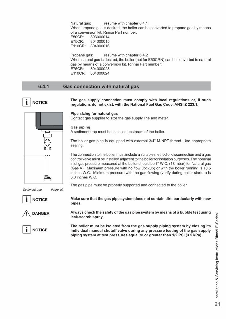
Gas pipingA sediment trap must be installed upstream of the boiler.
The boiler gas pipe is equipped with external 3/4" M-NPT thread. Use appropriate sealing.
The connection to the boiler must include a suitable method of disconnection and a gas control valve must be installed adjacent to the boiler for isolation purposes. The nominal inlet gas pressure measured at the boiler should be 7" W.C. (18 mbar) for Natural gas (Gas A). Maximum pressure with no fl ow (lockup) or with the boiler running is 10.5 inches W.C. Minimum pressure with the gas fl owing (verify during boiler startup) is 3.0 inches W.C.
The gas pipe must be properly supported and connected to the boiler.
Make sure that the gas pipe system does not contain dirt, particularly with new pipes.
Always check the safety of the gas pipe system by means of a bubble test using leak-search spray.
The boiler must be isolated from the gas supply piping system by closing its individual manual shutoff valve during any pressure testing of the gas supply piping system at test pressures equal to or greater than 1/2 PSI (3.5 kPa).
NOTICEi
NOTICEi
! DANGER
NOTICEi
Sediment trap fi gure 10
Inst
alla
tion
& Se
rvic
ing
Inst
ruct
ions
Rin
nai E
-Ser
ies
22
6.4.2 Gas connection with propane gas (not for E50CRN)
The gas supply connection must comply with local regulations or, if such regulations do not exist, with the National Fuel Gas Code, ANSI Z 223.1.
Pipe sizing for propane gas- Contact gas supplier to size pipes, tanks, and gas pressure regulator.
Propane Supply Pressure Requirements- Adjust propane supply regulator provided by the gas supplier for 14 inches W.C.
maximum pressure.- Pressure required at gas valve inlet pressure port: - Maximum 13.5 inches W.C. with no fl ow (lockup) or with boiler running. - Minimum 8 inches W.C. with gas fl owing (verify during boiler startup).
Ensure that the high gas pressure regulator is installed at least 6 to 10 feet upstream of the boiler.
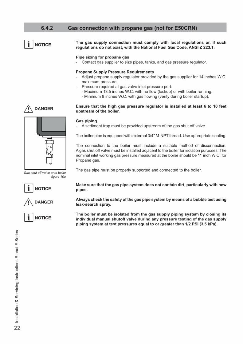
Gas piping- A sediment trap must be provided upstream of the gas shut off valve.
The boiler pipe is equipped with external 3/4" M-NPT thread. Use appropriate sealing.
The connection to the boiler must include a suitable method of disconnection. A gas shut off valve must be installed adjacent to the boiler for isolation purposes. The nominal inlet working gas pressure measured at the boiler should be 11 inch W.C. for Propane gas.
The gas pipe must be properly supported and connected to the boiler.
Make sure that the gas pipe system does not contain dirt, particularly with new pipes.
Always check the safety of the gas pipe system by means of a bubble test using leak-search spray.
The boiler must be isolated from the gas supply piping system by closing its individual manual shutoff valve during any pressure testing of the gas supply piping system at test pressures equal to or greater than 1/2 PSI (3.5 kPa).
Gas shut off valve onto boiler fi gure 10a
NOTICEi
NOTICEi
! DANGER
! DANGER
NOTICEi
Inst
alla
tion
& Se
rvic
ing
Inst
ruct
ions
Rin
nai E
-Ser
ies
23
6.5 Hot water supply
Connection of the drinking water installation should be performed according to the national secondary drinking water regulations.
Do NOT use toxic chemicals, such as those used for boiler treatment in potable water heating systems used for space heating.
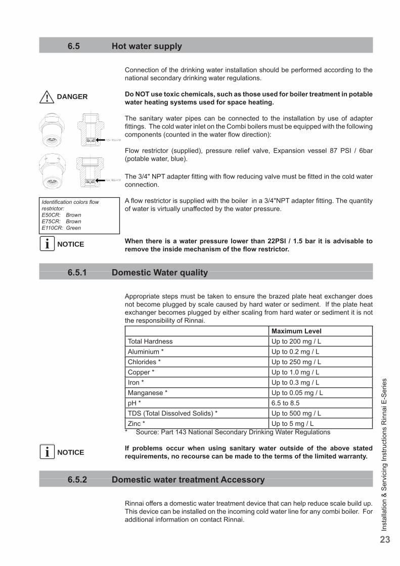
The sanitary water pipes can be connected to the installation by use of adapter fi ttings. The cold water inlet on the Combi boilers must be equipped with the following components (counted in the water fl ow direction):
Flow restrictor (supplied), pressure relief valve, Expansion vessel 87 PSI / 6bar (potable water, blue).
The 3/4" NPT adapter fi tting with fl ow reducing valve must be fi tted in the cold water connection.
A fl ow restrictor is supplied with the boiler in a 3/4"NPT adapter fi tting. The quantity of water is virtually unaff ected by the water pressure.
When there is a water pressure lower than 22PSI / 1.5 bar it is advisable to remove the inside mechanism of the fl ow restrictor.
6.5.1 Domestic Water quality
Appropriate steps must be taken to ensure the brazed plate heat exchanger does not become plugged by scale caused by hard water or sediment. If the plate heat exchanger becomes plugged by either scaling from hard water or sediment it is not the responsibility of Rinnai.
Maximum LevelTotal Hardness Up to 200 mg / LAluminium * Up to 0.2 mg / LChlorides * Up to 250 mg / LCopper * Up to 1.0 mg / LIron * Up to 0.3 mg / LManganese * Up to 0.05 mg / LpH * 6.5 to 8.5TDS (Total Dissolved Solids) * Up to 500 mg / LZinc * Up to 5 mg / L
* Source: Part 143 National Secondary Drinking Water Regulations
If problems occur when using sanitary water outside of the above stated requirements, no recourse can be made to the terms of the limited warranty.
6.5.2 Domestic water treatment Accessory
Rinnai off ers a domestic water treatment device that can help reduce scale build up. This device can be installed on the incoming cold water line for any combi boiler. For additional information on contact Rinnai.
NOTICEi
! DANGER
Identifi cation colors fl ow restrictor:E50CR: Brown E75CR: BrownE110CR: Green
NOTICEi
Inst
alla
tion
& Se
rvic
ing
Inst
ruct
ions
Rin
nai E
-Ser
ies
24
6.5.3 DHW Expansion Tank
A domestic water expansion tank could be required by local code. Check local code to determine if it is required.If a combi boiler is installed in a closed water supply system, such as one having a backfl ow preventer in the cold water supply line, means shall be provided to control thermal expansion. Contact the water supplier or local plumbing inspector on how to control thermal expansion.
6.5.4 Installing a Thermostatic Mixing Valve
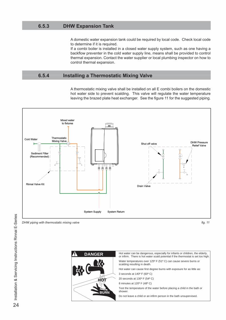
A thermostatic mixing valve shall be installed on all E combi boilers on the domestic hot water side to prevent scalding. This valve will regulate the water temperature leaving the brazed plate heat exchanger. See the fi gure 11 for the suggested piping.
DHW piping with thermostatic mixing valve fi g. 11
Hot water can be dangerous, especially for infants or children, the elderly, or infirm. There is hot water scald potential if the thermostat is set too high.
Water temperatures over 125º F (51º C) can cause severe burns or scalding resulting in death.
Hot water can cause first degree burns with exposure for as little as:
3 seconds at 140º F (60º C)
20 seconds at 130º F (54º C)
8 minutes at 120º F (48º C)
Test the temperature of the water before placing a child in the bath or shower.
Do not leave a child or an infirm person in the bath unsupervised.
DANGER
Inst
alla
tion
& Se
rvic
ing
Inst
ruct
ions
Rin
nai E
-Ser
ies
25
6.5.5 Installing a valve kit
A means to isolate the domestic plate heat exchanger for cleaning must be provide at installation. Refer to fi gure 10 for proper piping layout. A Rinnai valve kit can be used on domestic water pipes for all combi boilers to allow for cleaning of the plate heat exchanger and installation the domestic hot water pressure relief valve.• Rinnai recommends the use of a plumbing installation kit when connecting the
domestic water lines to the boiler. • Use of this kit will assist in fl ushing the fl at plate heat exchanger in areas where
water quality issues exist, as well as improve overall product serviceability.
6.5.6 Pressure relief Valve
- An approved pressure relief valve is required by Rinnai for all water heating systems.
- The relief valve must comply with the standard for Relief Valves and Automatic Gas Shutoff Devices for Hot Water Supply Systems ANSI Z21.22 and/or the standard Temperature, Pressure, Temperature and Pressure Relief Valves and Vacuum Relief Valves, CAN1-4.4.
- The relief valve must be rated up to 150 psi and to at least the maximum BTU/hr of the appliance.
- The discharge from the pressure relief valve should be piped to the ground or into a drain system to prevent exposure or possible burn hazards to humans or other plant or animal life. Follow local codes. Water discharged from the relief valve could cause severe burns instantly, scalds, or death.
- The pressure relief valve must be manually operated once a year to check for correct operation.
- The relief valve should be added to the hot water outlet line according to the manufacturer instructions. DO NOT place any other type valve or shut off device between the relief valve and the combi boiler.
- Do not plug the relief valve and do not install any reducing fi ttings or other restrictions in the relief line. The relief line should allow for complete drainage of the valve and the line.
- If a relief valve discharges periodically, this may be due to thermal expansion in a closed water supply system. Contact the water supplier or local plumbing inspector on how to correct this situation. Do not plug the relief valve.
- Rinnai does not require a combination temperature and pressure relief valve for this appliance. However local codes may require a combination temperature and pressure relief valve.
- If a combi boiler is installed in a closed water supply system, such as one having a backfl ow preventer in the cold water supply line, means shall be provided to control thermal expansion. Contact the water supplier or local plumbing inspector on how to control thermal expansion.
6.5.7 Programming domestic hot water preheat
When plate warming is selected the brazed plate heat exchanger is kept warm and this reduces the wait time for domestic hot water by approximately 1 minute. When this setting is turned off the wait time for DHW is increased by approximately 1 minute.
E50CRN Only: Plate warming can only be deactivated when the fl ow switch accessory (part number 803000015) has been installed. If no fl ow switch is installed and parameter 36 is altered from the factory setting no DHW production will be possible.
NOTICEi
Inst
alla
tion
& Se
rvic
ing
Inst
ruct
ions
Rin
nai E
-Ser
ies
26
If plate warming is selected consider the following. This product is a domestic hot water priority boiler; therefore continuous fl ow in the DHW system (perhaps due to a leaky fi xture) may cause the boiler to remain in DHW mode — thus preventing the heating system from adequately functioning. In the event the DHW system has a leak, this feature should be turned off until this problem can be corrected.
This selection can be done with the fi rst digit of Parameter 36. Domestic hot water preheat ON = 1x (Factory setting)Domestic hot water preheat OFF = 2xSee chapter 10 how to change a parameter.
The domestic hot water preheat setting is designed to increase the comfort of the home owner and reduce water consumption by reducing the wait time for hot water at the fi xture. This comfort setting will create a slight increase in the gas usage of the boiler, but this will be off set by the reduction in wasted water at the fi xture.
6.6 Condensate drain pipe
This boiler produces condensate. Condensate must be drained otherwise the boiler will not function and can cause product or property damage.
The condensation drain pipe should be connected to a drain in the building by means of an open connection. By this means the possibility of drain gases eff ecting the boiler is prevented. The drain connection should have a minimum diameter of 1.25" / 32mm.
Install the condensation drain pipe according to applicable local code.
If the condensate outlet of the boiler is lower than the public sewage system a condensate pump must be used. The condensate produced by the boiler has a pH value between 3 and 4.Install a neutralization unit if required by local code. It is recommended, but not required to install a condensate neutralizer. Rinnai off ers a condensate neutralizer designed to work with all boiler models. The condensate neutralizer kit comes with all the necessary fi ttings and mounting material. PVC pipe must be supplied by the installation contractor.Rinnai part number: 804000074
Do not drain the condensation water to the external rain gutter because of the danger of freezing and blockage of the drain.
Before putting the boiler into operation fi ll the condensate trap with 1.27 cups / 300 ml of water. If the boiler will be installed in a high temperature installation such as baseboard with a supply temperature of 160°F or above, fi ll the condensate trap with mineral oil instead of water.
Use materials approved by the authority having jurisdiction. In absence of such authority, PVC and CPVC pipe must comply with ASTM D1785, F441 or D2665. Cement and primer must comply with ASTM D2564 or F493.
Periodic cleaning of the condensate disposal system must be carried out. See the Rinnai Boiler Application Manual for further information and for a piping diagram for the condensate.
NOTICEiNOTICEi
NOTICEi
NOTICEi
NOTICEi
Inst
alla
tion
& Se
rvic
ing
Inst
ruct
ions
Rin
nai E
-Ser
ies
27
NOTICEi
NOTICEi
6.7 Vent system and air supply system
Provisions for combustion and ventilation air must be made in accordance with section, Air for Combustion and Ventilation of the National Flue Gas Code, ANSI Z223.1, or applicable provisions of the local building codes.
- Do not store chemicals near the boiler or in rooms where the air is being supplied to the boiler. See the list on page 10.
- Do not allow the fl ue gases of other appliances to enter the boiler.- Keep cabinet free of moisture
In the event that the system has actuated to shut off the main burner gas, do not attempt to place the boiler in operation. Contact a qualifi ed service agency.
6.7.1 Intake / Exhaust Guidelines
Refer to the specifi c instructions on your vent product for additional installation requirements.
• For direct vent boilers, proper reassembly and resealing of the vent-air intake system is required.
• You must use vent components that are certifi ed and listed with this model.• Do not combine vent components from diff erent manufacturers.• Venting should be as direct as possible with a minimum number of pipe fi ttings.• Avoid dips or sags in horizontal vent runs by installing supports per the vent
manufacturer’s instructions.• Support horizontal vent runs every four feet and all vertical vent runs every six
feet or in accordance with local codes.• Vent diameter may be reduced to 2" (see table 9).• The boiler is unsuitable to install on a common vent installation, see also chapter 18.• Do not connect the venting system with an existing vent or chimney.• Do not common vent with the vent pipe of any other boiler or appliance.• Vent connections must be fi rmly pressed together so that the gaskets form an air
tight seal.• Refer to the instructions of the vent system manufacturer for component assembly
instructions.• If the vent system is to be enclosed, it is suggested that the design of the enclosure
shall permit inspection of the vent system. The design of such enclosure shall be deemed acceptable by the installer or the local inspector.
If it becomes necessary to access an enclosed vent system for service or repairs, Rinnai is not responsible for any costs or diffi culties in accessing the vent system. The limited warranty does not cover obtaining access to an enclosed vent system.
The instructions for the installations of the venting system shall specify that the horizontal portions of the venting system shall be supported to prevent sagging; the methods of and intervals for support shall be specifi ed. These instructions shall also specify that the venting system:• For category I, II and IV boilers, have horizontal runs sloping upwards not
less than 1/4" per foot (21mm/m) from the boiler to the vent terminal;• For category III boilers, slope shall be as specifi ed in the boiler manufacturer's instructions;• For category II and IV boilers, be installed so as to prevent accumulation of
condensate; and• For category II and IV boilers, where necessary, have means provided for
drainage of condensate.
Inst
alla
tion
& Se
rvic
ing
Inst
ruct
ions
Rin
nai E
-Ser
ies
28
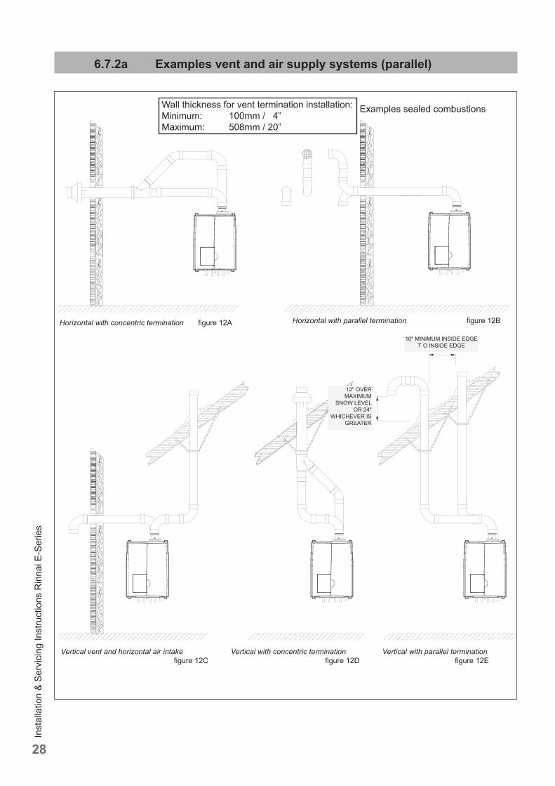
Vertical vent and horizontal air intake fi gure 12C
Vertical with concentric termination fi gure 12D
Horizontal with concentric termination fi gure 12A Horizontal with parallel termination fi gure 12B
Examples sealed combustions
Vertical with parallel termination fi gure 12E
Wall thickness for vent termination installation:Minimum: 100mm / 4”Maximum: 508mm / 20”
10" MINIMUM INSIDE EDGE T`O INSIDE EDGE
12" OVER MAXIMUM
SNOW LEVEL OR 24"
WHICHEVER IS GREATER
6.7.2a Examples vent and air supply systems (parallel)
Inst
alla
tion
& Se
rvic
ing
Inst
ruct
ions
Rin
nai E
-Ser
ies
29
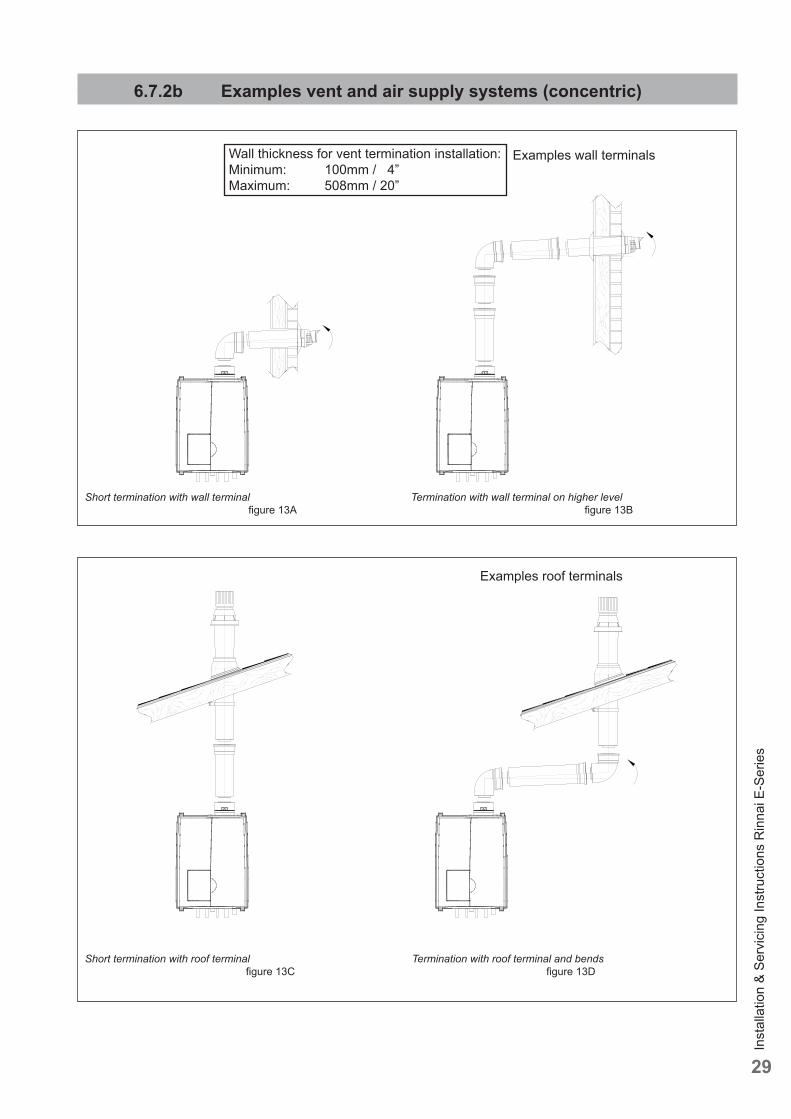
Short termination with roof terminal fi gure 13C
Termination with roof terminal and bends fi gure 13D
Short termination with wall terminal fi gure 13A
Termination with wall terminal on higher level fi gure 13B
Examples roof terminals
Examples wall terminalsWall thickness for vent termination installation:Minimum: 100mm / 4”Maximum: 508mm / 20”
6.7.2b Examples vent and air supply systems (concentric)
Inst
alla
tion
& Se
rvic
ing
Inst
ruct
ions
Rin
nai E
-Ser
ies
30
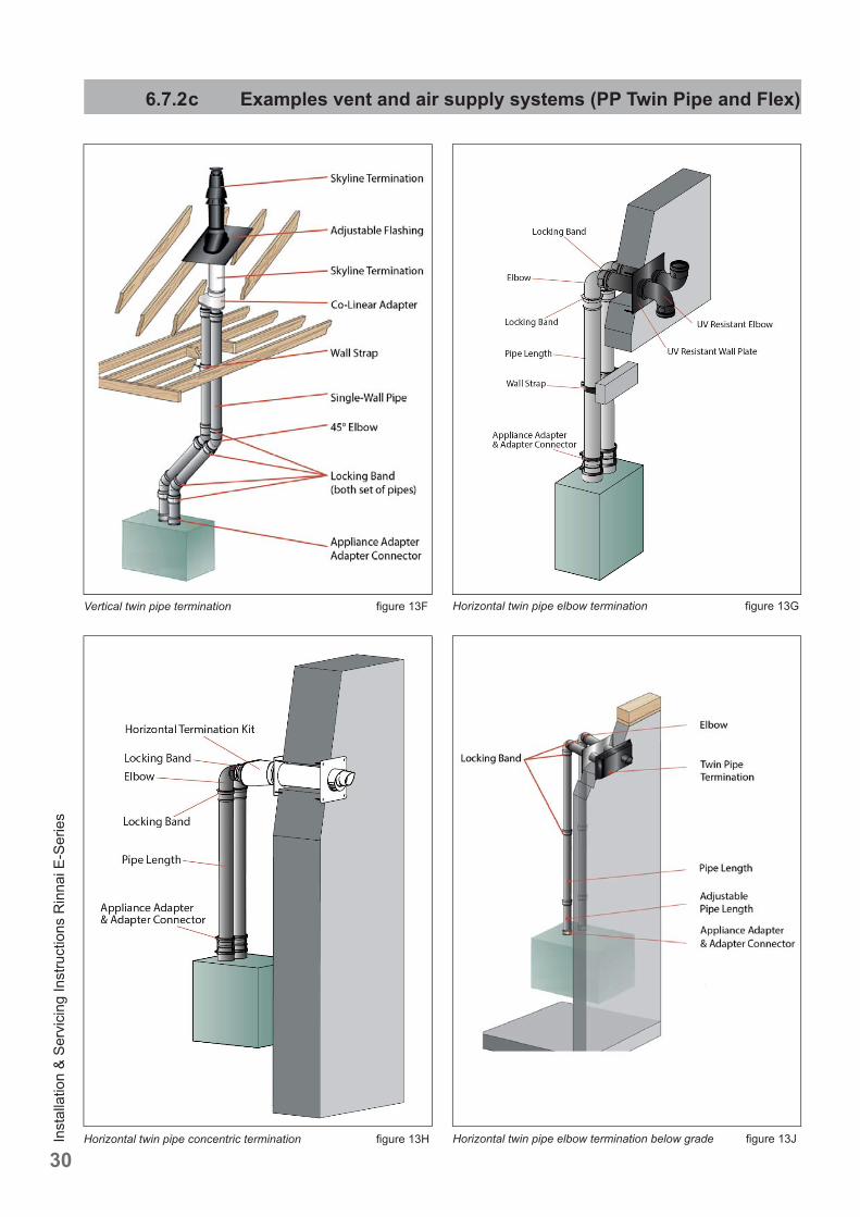
6.7.2 c Examples vent and air supply systems (PP Twin Pipe and Flex)
Vertical twin pipe termination fi gure 13F Horizontal twin pipe elbow termination fi gure 13G
Horizontal twin pipe concentric termination fi gure 13H Horizontal twin pipe elbow termination below grade fi gure 13J
Inst
alla
tion
& Se
rvic
ing
Inst
ruct
ions
Rin
nai E
-Ser
ies
31
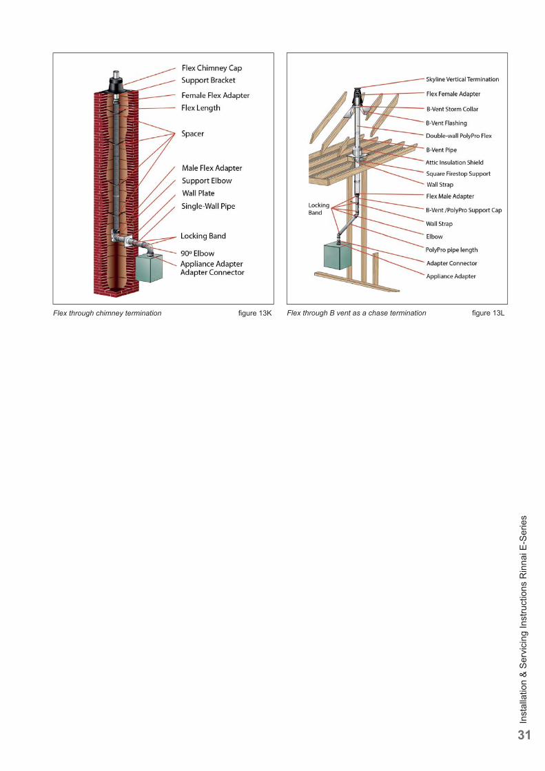
Flex through chimney termination fi gure 13K Flex through B vent as a chase termination fi gure 13L
Inst
alla
tion
& Se
rvic
ing
Inst
ruct
ions
Rin
nai E
-Ser
ies
32
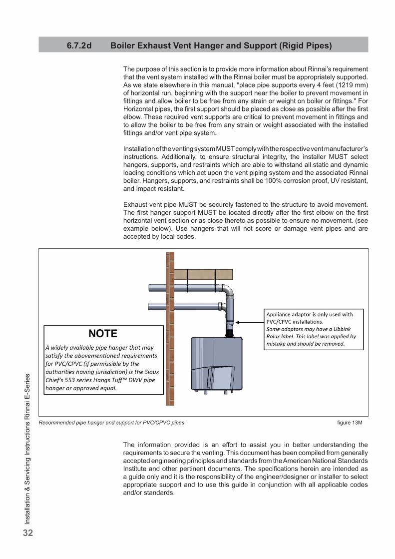
6.7.2 d Boiler Exhaust Vent Hanger and Support (Rigid Pipes)
The purpose of this section is to provide more information about Rinnai’s requirement that the vent system installed with the Rinnai boiler must be appropriately supported. As we state elsewhere in this manual, "place pipe supports every 4 feet (1219 mm) of horizontal run, beginning with the support near the boiler to prevent movement in fi ttings and allow boiler to be free from any strain or weight on boiler or fi ttings." For Horizontal pipes, the fi rst support should be placed as close as possible after the fi rst elbow. These required vent supports are critical to prevent movement in fi ttings and to allow the boiler to be free from any strain or weight associated with the installed fi ttings and/or vent pipe system.
Installation of the venting system MUST comply with the respective vent manufacturer’s instructions. Additionally, to ensure structural integrity, the installer MUST select hangers, supports, and restraints which are able to withstand all static and dynamic loading conditions which act upon the vent piping system and the associated Rinnai boiler. Hangers, supports, and restraints shall be 100% corrosion proof, UV resistant, and impact resistant.
Exhaust vent pipe MUST be securely fastened to the structure to avoid movement. The fi rst hanger support MUST be located directly after the fi rst elbow on the fi rst horizontal vent section or as close thereto as possible to ensure no movement. (see example below). Use hangers that will not score or damage vent pipes and are accepted by local codes.
The information provided is an eff ort to assist you in better understanding the requirements to secure the venting. This document has been compiled from generally accepted engineering principles and standards from the American National Standards Institute and other pertinent documents. The specifi cations herein are intended as a guide only and it is the responsibility of the engineer/designer or installer to select appropriate support and to use this guide in conjunction with all applicable codes and/or standards.
Recommended pipe hanger and support for PVC/CPVC pipes fi gure 13M
Inst
alla
tion
& Se
rvic
ing
Inst
ruct
ions
Rin
nai E
-Ser
ies
33
6.7.3 Installation of the vent system
Consult local and state codes pertaining to special building code and fi re department requirements. Adhere to national code requirements.
Follow the listed maximum length of vent systems, which are boiler output dependent. The maximum permissible lengths are listed in table 9, chapter 6.7.6.
Decide how to install the exhaust and air intake system. You can choose between:
- Parallel system (see chapter 6.7.2a)The parallel connection is provided standard initially on the E50CRN.The boiler connection diameter is 2x 3" (80mm). In this case a separate supplied kit, with 2 vent adapters 3" should be fi tted on top of the boiler, to which the venting and air supply system can be fi tted, with or without elbow pieces. The maximum permissible pipe length is set out in table 9, chapter 6.7.6.The E75CR and E110CR boilers are provided standard initially with a concentric connection, but can be converted to a parallel system with supplied adapters.
- Concentric system (see chapter 6.7.2b) The concentric connection is provided standard initially on the E75CR and E110CR.The boiler connection diameter is concentric 80/125mm) to which the concentric venting and air supply system can be fi tted, with or without elbow pieces. The maximum permissible pipe length is set out in table 9, chapter 6.7.6.The E50CRN boiler is provided standard initially with a parallel connection, but can be converted to a concentric system with with an optional adapter (Part nr. 808000023).
- Room Air System (indoor combustion air)The boiler can use room air for combustion. If this option is selected the boiler must be provided with a parallel vent system. A single exhaust pipe can then be fi tted. It is required to use a room air fi lter (Part nr. 808000025) when using indoor air for combustion. See chapter 6.7.3.2 for installation. The maximum permissible pipe length is set out in table 9, chapter 6.7.6.
Rinnai strongly recommends the use of the room air fi lter when a Room Air System (indoor combustion air) is used.
When the boiler is installed in any of the areas listed in chapter 5.1, "Areas likely to have contaminants" or any area exposed to the contaminants listed in chapter 5.1, then sealed combustion is required.
We advise to install a vent system out of the venting system program supplied by Rinnai (See chapter 19 Parts list Vent system). For further information about the available components of the venting and air supply system we recommend you consult Rinnai and the Installation instructions and parts list documentation.
NOTICEiNOTICEi
NOTICEi
NOTICEi
NOTICEi
Inst
alla
tion
& Se
rvic
ing
Inst
ruct
ions
Rin
nai E
-Ser
ies
34
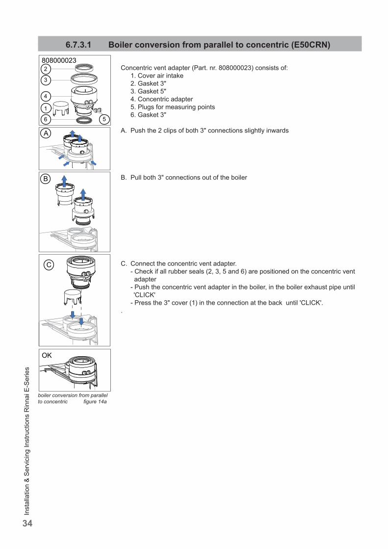
6.7.3.1 Boiler conversion from parallel to concentric (E50CRN)
Concentric vent adapter (Part. nr. 808000023) consists of: 1. Cover air intake 2. Gasket 3" 3. Gasket 5" 4. Concentric adapter 5. Plugs for measuring points 6. Gasket 3"
A. Push the 2 clips of both 3" connections slightly inwards
B. Pull both 3" connections out of the boiler
C. Connect the concentric vent adapter. - Check if all rubber seals (2, 3, 5 and 6) are positioned on the concentric vent adapter - Push the concentric vent adapter in the boiler, in the boiler exhaust pipe until 'CLICK' - Press the 3" cover (1) in the connection at the back until 'CLICK'..
OK
C
A
B
1
2
3
4
6 5
808000023
boiler conversion from parallel to concentric fi gure 14a
Inst
alla
tion
& Se
rvic
ing
Inst
ruct
ions
Rin
nai E
-Ser
ies
35
placing air fi lter on air intake fi gure 14c
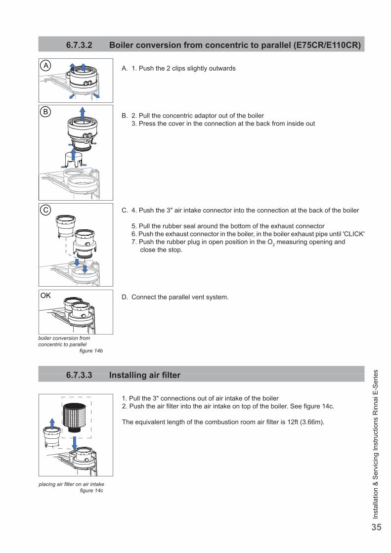
6.7.3.2 Boiler conversion from concentric to parallel (E75CR/E110CR)
A. 1. Push the 2 clips slightly outwards
B. 2. Pull the concentric adaptor out of the boiler 3. Press the cover in the connection at the back from inside out
C. 4. Push the 3" air intake connector into the connection at the back of the boiler
5. Pull the rubber seal around the bottom of the exhaust connector 6. Push the exhaust connector in the boiler, in the boiler exhaust pipe until 'CLICK' 7. Push the rubber plug in open position in the O2 measuring opening and close the stop.
D. Connect the parallel vent system.
6.7.3.3 Installing air fi lter
1. Pull the 3" connections out of air intake of the boiler2. Push the air fi lter into the air intake on top of the boiler. See fi gure 14c.
The equivalent length of the combustion room air fi lter is 12ft (3.66m).
A
OK
C
B
boiler conversion from concentric to parallel fi gure 14b
Inst
alla
tion
& Se
rvic
ing
Inst
ruct
ions
Rin
nai E
-Ser
ies
36
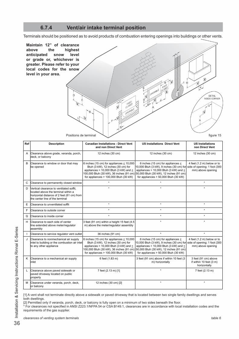
6.7.4 Vent/air intake terminal positionTerminals should be positioned as to avoid products of combustion entering openings into buildings or other vents.
Maintain 12” of clearance above the highest anticipated snow level or grade or, whichever is greater. Please refer to your local codes for the snow level in your area.
Positions de terminal fi gure 15
clearances of venting system terminals table 6
[1] A vent shall not terminate directly above a sidewalk or paved driveway that is located between two single family dwellings and serves both dwellings.[2] Permitted only if veranda, porch, deck, or balcony is fully open on a minimum of two sides beneath the fl oor.* For clearances not specifi ed in ANSI Z223.1/NFPA 54 or CSA B149.1, clearances are in accordance with local installation codes and the requirements of the gas supplier.
Ref Description Canadian Installations - Direct Vent and non Direct Vent
US Installations Direct Vent US Installations non Direct Vent
A Clearance above grade, veranda, porch, deck, or balcony
12 inches (30 cm) 12 inches (30 cm) 12 inches (30 cm)
B Clearance to window or door that may be opened
6 inches (15 cm) for appliances < 10,000 Btuh (3 kW), 12 inches (30 cm) for
appliances > 10,000 Btuh (3 kW) and < 100,000 Btuh (30 kW), 36 inches (91 cm)
for appliances > 100,000 Btuh (30 kW)
6 inches (15 cm) for appliances < 10,000 Btuh (3 kW), 9 inches (30 cm) for appliances > 10,000 Btuh (3 kW) and < 50,000 Btuh (30 kW), 12 inches (91 cm)
for appliances > 50,000 Btuh (30 kW)
4 feet (1.2 m) below or to side of opening; 1 foot (300
mm) above opening
C Clearance to permanently closed window * * *
D Vertical clearance to ventilated soffi t, located above the terminal within a horizontal distance of 2 feet (61 cm) from the center line of the terminal
* * *
E Clearance to unventilated soffi t * * *
F Clearance to outside corner * * *
G Clearance to inside corner * * *
H Clearance to each side of center line extended above meter/regulator assembly
3 feet (91 cm) within a height 15 feet (4.5 m) above the meter/regulator assembly
* *
I Clearance to service regulator vent outlet 36 inches (91 cm) * *
J Clearance to nonmechanical air supply inlet to building or the combustion air inlet to any other appliance
6 inches (15 cm) for appliances < 10,000 Btuh (3 kW), 12 inches (30 cm) for
appliances > 10,000 Btuh (3 kW) and < 100,000 Btuh (30 kW), 36 inches (91 cm)
for appliances > 100,000 Btuh (30 kW)
6 inches (15 cm) for appliances < 10,000 Btuh (3 kW), 9 inches (30 cm) for appliances > 10,000 Btuh (3 kW) and < 50,000 Btuh (30 kW), 12 inches (91 cm)
for appliances > 50,000 Btuh (30 kW)
4 feet (1.2 m) below or to side of opening; 1 foot (300
mm) above opening
K Clearance to a mechanical air supply inlet
6 feet (1.83 m) 3 feet (91 cm) above if within 10 feet (3 m) horizontally
3 feet (91 cm) above if within 10 feet (3 m)
horizontally
L Clearance above paved sidewalk or paved driveway located on public property
7 feet (2.13 m) [1] * 7 feet (2.13 m)
M Clearance under veranda, porch, deck, or balcony
12 inches (30 cm) [2] * *
Inst
alla
tion
& Se
rvic
ing
Inst
ruct
ions
Rin
nai E
-Ser
ies
37
Terminals should be positioned as to avoid products of combustion entering openings into buildings or other vents.
Maintain 12” of clearance above the highest anticipated snow level or grade or, whichever is greater. Please refer to your local codes for the snow level in your area.
The termination shall be at least 4 feet (1,220 mm) distance from electric meters, gas meters, regulators and relief equipment. (for room air application only)
Horizontal vent systems should always be installed sloping towards the boiler (min. 21 mm/m, 1/4”/ feet), in order to avoid condensate retaining in the vent system. With the condensate running back to the boiler the risk of ice forming at the terminal is reduced.
The whole route of the exhaust vent system must be installed upwards, never downwards, completely nor partly.
Place pipe supports every 4 feet (1219 mm) of horizontal run, beginning with the support near the boiler to prevent movement in fi ttings and allow boiler to be free from any strain or weight on boiler or fi ttings.
The terminal should be located where dispersal of combustion products is not impeded and with due regard for the damage or discoloration that might occur to building products or vegetation in the vicinity (see fi g 15 and 16).
In certain weather conditions condensation may also accumulate on the outside of the air inlet pipe. Such conditions must be considered and where necessary insulation of the inlet pipe may be required.In cold and/or humid weather water vapor may condense on leaving the vent terminal. The eff ect of such ‘water condensation’ must be considered. The terminal must be located in a place not likely to cause a nuisance.
Cellular or Foam core PVC, CPVC and Radel is not permitted for use with the boiler.
The application of any type of insulation is prohibited for use with any Plastic venting system.
NOTICEi
! CAUTION
! CAUTION
NOTICEi
NOTICEiNOTICEi
NOTICEi
Approval codes for installation of venting system table 7
NOTICEi
NOTICEi
NOTICEi
Inst
alla
tion
& Se
rvic
ing
Inst
ruct
ions
Rin
nai E
-Ser
ies
38
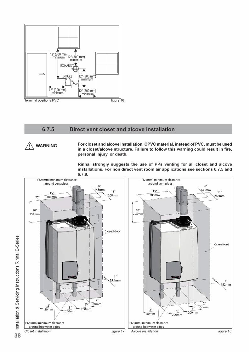
6.7.5 Direct vent closet and alcove installation
For closet and alcove installation, CPVC material, instead of PVC, must be used in a closet/alcove structure. Failure to follow this warning could result in fi re, personal injury, or death.
Rinnai strongly suggests the use of PPs venting for all closet and alcove installations. For non direct vent room air applications see sections 6.7.5 and 6.7.8.
12" (300 mm)minimum 12" (300 mm)
minimum
12" (300 mm)minimum
INTAKE
EXHAUST
12" (300 mm)minimum
12" (300 mm)minimum
Terminal positions PVC fi gure 16
! WARNING
15”386mm
6”148mm 11”
268mm
Closed door
1”25,4mm
10”254mm
1”(25mm) minimum clearancearound vent pipes
2”50mm2”
50mm
1”(25mm) minimum clearancearound hot water pipes
8”200mm
8”200mm
Closet installation fi gure 17
10”254mm
15”386mm
1”(25mm) minimum clearancearound vent pipes
6”148mm
11”268mm
Open front
6”152mm
2”50mm
8”200mm
8”200mm
2”50mm
1”(25mm) minimum clearancearound hot water pipes
Alcove installation fi gure 18
Inst
alla
tion
& Se
rvic
ing
Inst
ruct
ions
Rin
nai E
-Ser
ies
39
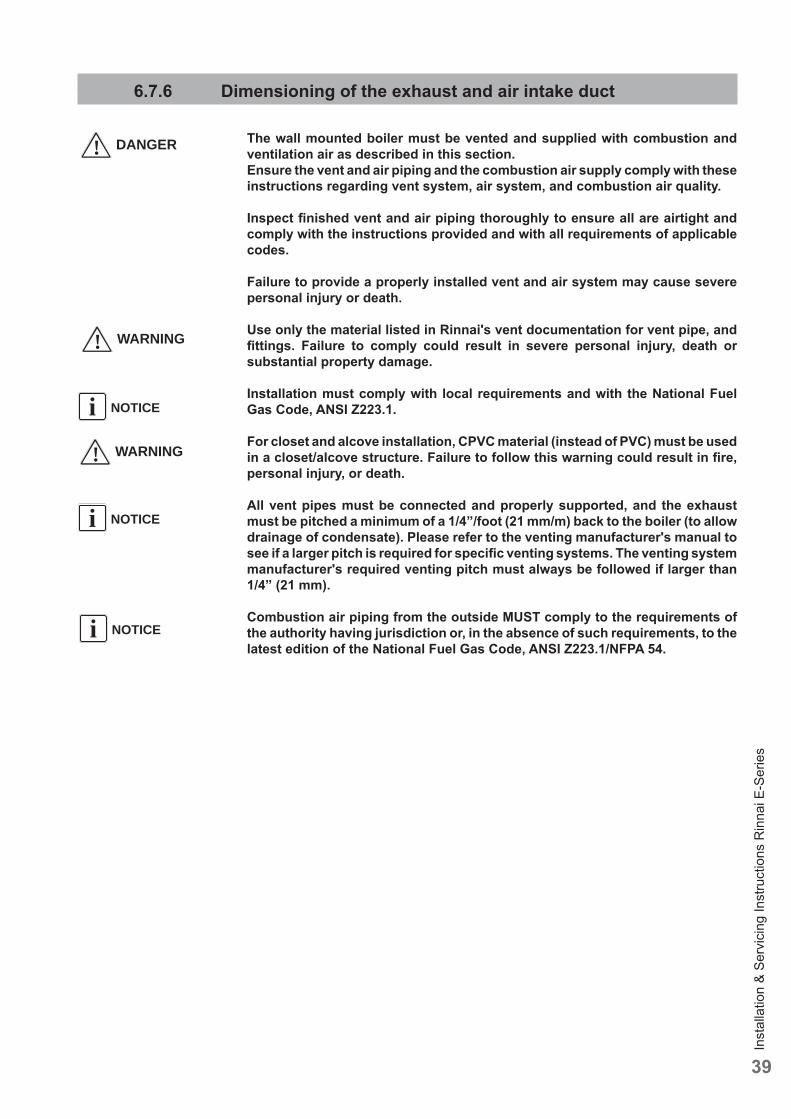
6.7.6 Dimensioning of the exhaust and air intake duct
The wall mounted boiler must be vented and supplied with combustion and ventilation air as described in this section.Ensure the vent and air piping and the combustion air supply comply with these instructions regarding vent system, air system, and combustion air quality.
Inspect fi nished vent and air piping thoroughly to ensure all are airtight and comply with the instructions provided and with all requirements of applicable codes.
Failure to provide a properly installed vent and air system may cause severe personal injury or death.
Use only the material listed in Rinnai's vent documentation for vent pipe, and fi ttings. Failure to comply could result in severe personal injury, death or substantial property damage.
Installation must comply with local requirements and with the National Fuel Gas Code, ANSI Z223.1.
For closet and alcove installation, CPVC material (instead of PVC) must be used in a closet/alcove structure. Failure to follow this warning could result in fi re, personal injury, or death.
All vent pipes must be connected and properly supported, and the exhaust must be pitched a minimum of a 1/4”/foot (21 mm/m) back to the boiler (to allow drainage of condensate). Please refer to the venting manufacturer's manual to see if a larger pitch is required for specifi c venting systems. The venting system manufacturer's required venting pitch must always be followed if larger than 1/4” (21 mm).
Combustion air piping from the outside MUST comply to the requirements of the authority having jurisdiction or, in the absence of such requirements, to the latest edition of the National Fuel Gas Code, ANSI Z223.1/NFPA 54.
NOTICEi
! DANGER
NOTICEi
NOTICEi
! WARNING
! WARNING
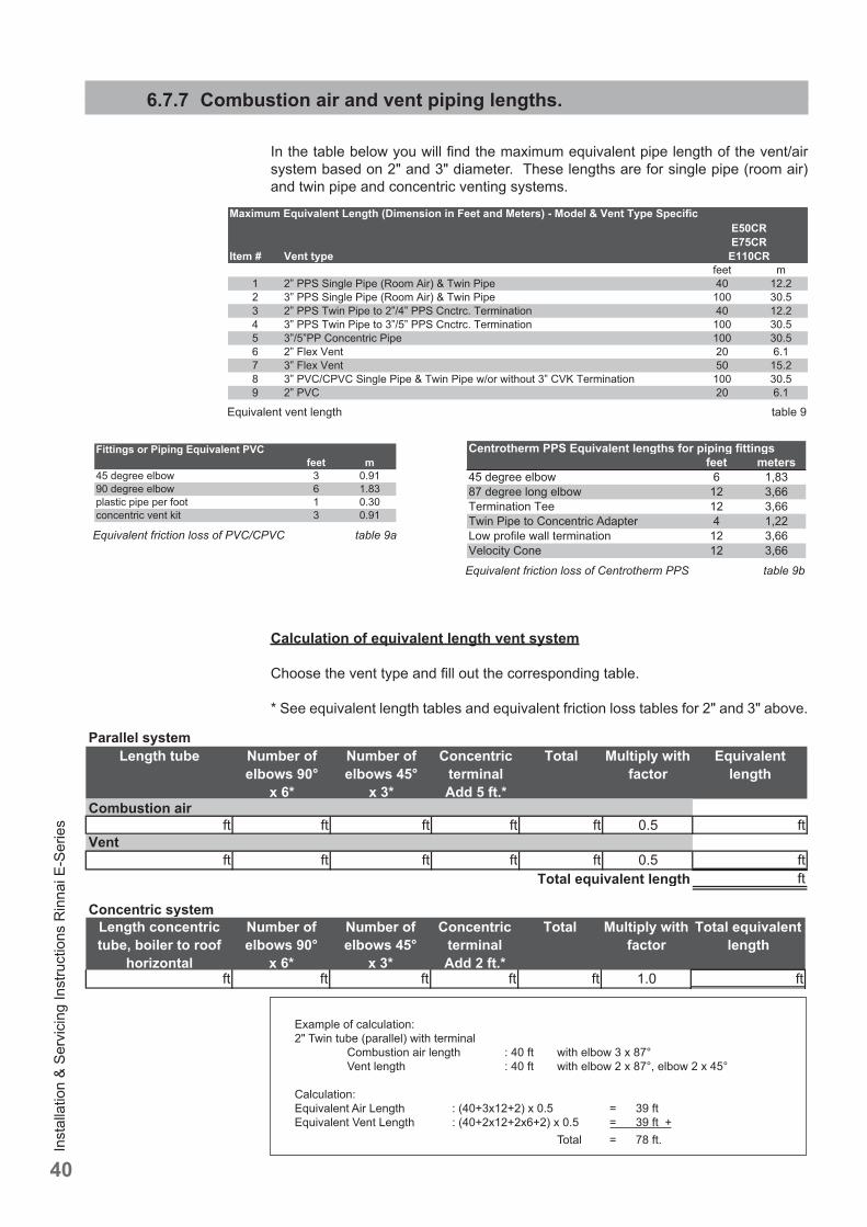
Inst
alla
tion
& Se
rvic
ing
Inst
ruct
ions
Rin
nai E
-Ser
ies
40
Calculation of equivalent length vent system
Choose the vent type and fi ll out the corresponding table.
* See equivalent length tables and equivalent friction loss tables for 2" and 3" above.
Example of calculation: 2" Twin tube (parallel) with terminal Combustion air length : 40 ft with elbow 3 x 87° Vent length : 40 ft with elbow 2 x 87°, elbow 2 x 45°
Calculation: Equivalent Air Length : (40+3x12+2) x 0.5 = 39 ft Equivalent Vent Length : (40+2x12+2x6+2) x 0.5 = 39 ft + Total = 78 ft.
6.7.7 Combustion air and vent piping lengths.
In the table below you will fi nd the maximum equivalent pipe length of the vent/air system based on 2" and 3" diameter. These lengths are for single pipe (room air) and twin pipe and concentric venting systems.
Equivalent vent length table 9
Parallel systemLength tube Number of
elbows 90° x 6*
Number of elbows 45°
x 3*
ConcentricterminalAdd 5 ft.*
Total Multiply with factor
Equivalentlength
Combustion airft ft ft ft ft 0.5 ft
Ventft ft ft ft ft 0.5 ft
ftTotal equivalent length
Concentric systemLength concentric tube, boiler to roof
horizontal
Number of elbows 90°
x 6*
Number of elbows 45°
x 3*
ConcentricterminalAdd 2 ft.*
Total Multiply with factor
Total equivalent length
ft ft ft ft ft 1.0 ft
Equivalent friction loss of PVC/CPVC table 9a
Equivalent friction loss of Centrotherm PPS table 9b
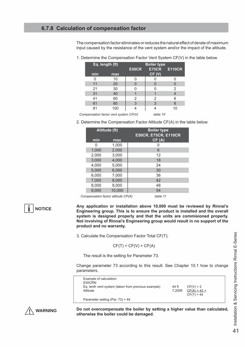
Inst
alla
tion
& Se
rvic
ing
Inst
ruct
ions
Rin
nai E
-Ser
ies
41
6.7.8 Calculation of compensation factor
The compensation factor eliminates or reduces the natural eff ect of derate of maximum input caused by the resistance of the vent system and/or the impact of the altitude.
1. Determine the Compensation Factor Vent System CF(V) in the table below.
2. Determine the Compensation Factor Altitude CF(A) in the table below.
Any application or installation above 10,000 must be reviewed by Rinnai's Engineering group. This is to ensure the product is installed and the overall system is designed properly and that the units are commisioned properly. Not involving of Rinnai's Engineering group would result in no support of the product and no warranty.
3. Calculate the Compensation Factor Total CF(T):
CF(T) = CF(V) + CF(A)
The result is the setting for Parameter 73.
Change parameter 73 according to this result. See Chapter 10.1 how to change parameters.
Example of calculation: E50CRN Eq. lenth vent system (taken from previous example) 44 ft CF(V) = 2 Altitude 7,200ft CF(A) = 42 + CF(T) = 44 Parameter setting (Par. 73) = 44
Do not overcompensate the boiler by setting a higher value than calculated, otherwise the boiler could be damaged.
Compensation factor vent system CP(V) table 10
Compensation factor altitude CP(A) table 11
! WARNING
NOTICEi
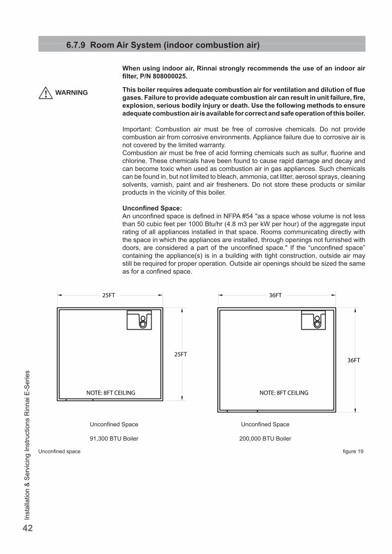
Inst
alla
tion
& Se
rvic
ing
Inst
ruct
ions
Rin
nai E
-Ser
ies
42
6.7.9 Room Air System (indoor combustion air)
When using indoor air, Rinnai strongly recommends the use of an indoor air fi lter, P/N 808000025.
This boiler requires adequate combustion air for ventilation and dilution of fl ue gases. Failure to provide adequate combustion air can result in unit failure, fi re, explosion, serious bodily injury or death. Use the following methods to ensure adequate combustion air is available for correct and safe operation of this boiler.
Important: Combustion air must be free of corrosive chemicals. Do not provide combustion air from corrosive environments. Appliance failure due to corrosive air is not covered by the limited warranty.Combustion air must be free of acid forming chemicals such as sulfur, fl uorine and chlorine. These chemicals have been found to cause rapid damage and decay and can become toxic when used as combustion air in gas appliances. Such chemicals can be found in, but not limited to bleach, ammonia, cat litter, aerosol sprays, cleaning solvents, varnish, paint and air fresheners. Do not store these products or similar products in the vicinity of this boiler.
Unconfi ned Space:An unconfi ned space is defi ned in NFPA #54 "as a space whose volume is not less than 50 cubic feet per 1000 Btu/hr (4.8 m3 per kW per hour) of the aggregate input rating of all appliances installed in that space. Rooms communicating directly with the space in which the appliances are installed, through openings not furnished with doors, are considered a part of the unconfi ned space." If the “unconfi ned space” containing the appliance(s) is in a building with tight construction, outside air may still be required for proper operation. Outside air openings should be sized the same as for a confi ned space.
Unconfi ned Space
91,300 BTU Boiler
Unconfi ned Space
200,000 BTU Boiler
25FT
NOTE: 8FT CEILING
25FT
36FT
NOTE: 8FT CEILING
36FT
Unconfi ned space fi gure 19
! WARNING
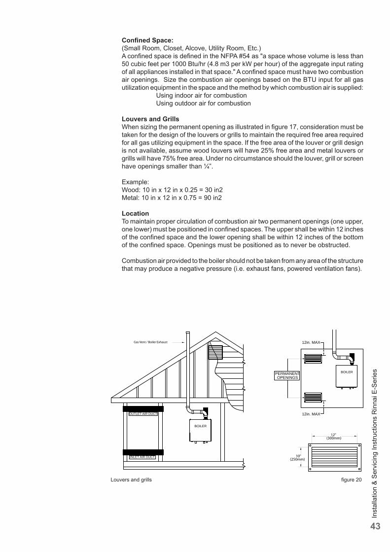
Inst
alla
tion
& Se
rvic
ing
Inst
ruct
ions
Rin
nai E
-Ser
ies
43
OUTLET AIR DUCT
INLET AIR DUCT
Gas Vent / Boiler Exhaust
BOILER
12in. MAX
12in. MAX
PERMANENTOPENINGS
BOILER
10"(250mm)
12"(300mm)
Louvers and grills fi gure 20
Confi ned Space:(Small Room, Closet, Alcove, Utility Room, Etc.)A confi ned space is defi ned in the NFPA #54 as "a space whose volume is less than 50 cubic feet per 1000 Btu/hr (4.8 m3 per kW per hour) of the aggregate input rating of all appliances installed in that space." A confi ned space must have two combustion air openings. Size the combustion air openings based on the BTU input for all gas utilization equipment in the space and the method by which combustion air is supplied: Using indoor air for combustion Using outdoor air for combustion
Louvers and GrillsWhen sizing the permanent opening as illustrated in fi gure 17, consideration must be taken for the design of the louvers or grills to maintain the required free area required for all gas utilizing equipment in the space. If the free area of the louver or grill design is not available, assume wood louvers will have 25% free area and metal louvers or grills will have 75% free area. Under no circumstance should the louver, grill or screen have openings smaller than ¼”.
Example:Wood: 10 in x 12 in x 0.25 = 30 in2Metal: 10 in x 12 in x 0.75 = 90 in2
LocationTo maintain proper circulation of combustion air two permanent openings (one upper, one lower) must be positioned in confi ned spaces. The upper shall be within 12 inches of the confi ned space and the lower opening shall be within 12 inches of the bottom of the confi ned space. Openings must be positioned as to never be obstructed.
Combustion air provided to the boiler should not be taken from any area of the structure that may produce a negative pressure (i.e. exhaust fans, powered ventilation fans).
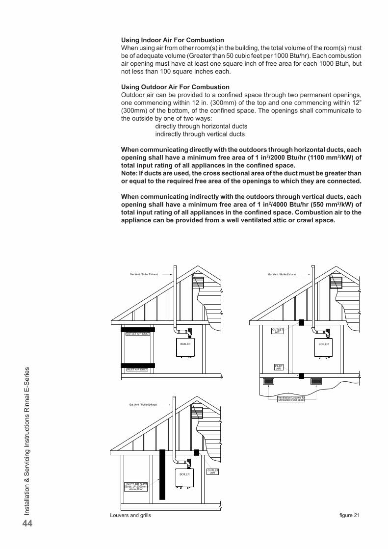
Inst
alla
tion
& Se
rvic
ing
Inst
ruct
ions
Rin
nai E
-Ser
ies
44
Using Indoor Air For CombustionWhen using air from other room(s) in the building, the total volume of the room(s) must be of adequate volume (Greater than 50 cubic feet per 1000 Btu/hr). Each combustion air opening must have at least one square inch of free area for each 1000 Btuh, but not less than 100 square inches each.
Using Outdoor Air For CombustionOutdoor air can be provided to a confi ned space through two permanent openings, one commencing within 12 in. (300mm) of the top and one commencing within 12” (300mm) of the bottom, of the confi ned space. The openings shall communicate to the outside by one of two ways: directly through horizontal ducts indirectly through vertical ducts
When communicating directly with the outdoors through horizontal ducts, each opening shall have a minimum free area of 1 in2/2000 Btu/hr (1100 mm2/kW) of total input rating of all appliances in the confi ned space. Note: If ducts are used, the cross sectional area of the duct must be greater than or equal to the required free area of the openings to which they are connected.
When communicating indirectly with the outdoors through vertical ducts, each opening shall have a minimum free area of 1 in2/4000 Btu/hr (550 mm2/kW) of total input rating of all appliances in the confi ned space. Combustion air to the appliance can be provided from a well ventilated attic or crawl space.
OUTLET AIR DUCT
INLET AIR DUCT
Gas Vent / Boiler Exhaust
BOILER
OUTLETAIR
INLETAIR
Ventilation Louvers forunheated crawl space
Gas Vent / Boiler Exhaust
BOILER
OUTLETAIR
INLET AIR DUCT[Ends 1Ft (300mm)
above floor]
Gas Vent / Boiler Exhaust
BOILER
Louvers and grills fi gure 21
Inst
alla
tion
& Se
rvic
ing
Inst
ruct
ions
Rin
nai E
-Ser
ies
45
7 Electrical connections
The electrical connections to the boiler must be electrically grounded in accordance with all applicable local codes and the latest revision of the National Electrical Code, ANSI/NFPA-70.
Devices such as, outdoor sensor, room thermostat or temperature control, and temperature sensor or thermostat are all connected to the internal connection terminal. The connection terminal is situated behind the Control Tower.
Connecting incoming powerInstall a 120V main switch next to the boiler as service main switch of the boiler.Lead the cable through the back part of the boiler using a strain relief and lead the cable through the cable supports to the Control Tower. Use a step drill bit to create a knockout in the grey plastic cover of the boiler for a strain relief.Connect a power supply cable to the cable harness terminal strip that connects to both the power switch on the front of the Control Tower and the terminal strip with positions 1, 2, and 3 on the inside of the Control Tower.
The boiler must be electrically grounded in accordance with local codes, or in absence of local codes, with the National Electrical Code, ANSI/INFPA 70.
RISK OF ELECTRIC SHOCK.Once the main power supply is on then there is 120V on terminals 1 to 12 when the main switch next to the boiler is switched on.
- No changes may be made to the wiring of the boiler;- All connections should be designed in accordance with the applicable
regulations;- Label all wires prior to disconnection when servicing controls. Wiring errors
can cause improper and dangerous operation.
CAUTION
CAUTION
CAUTION
! CAUTION
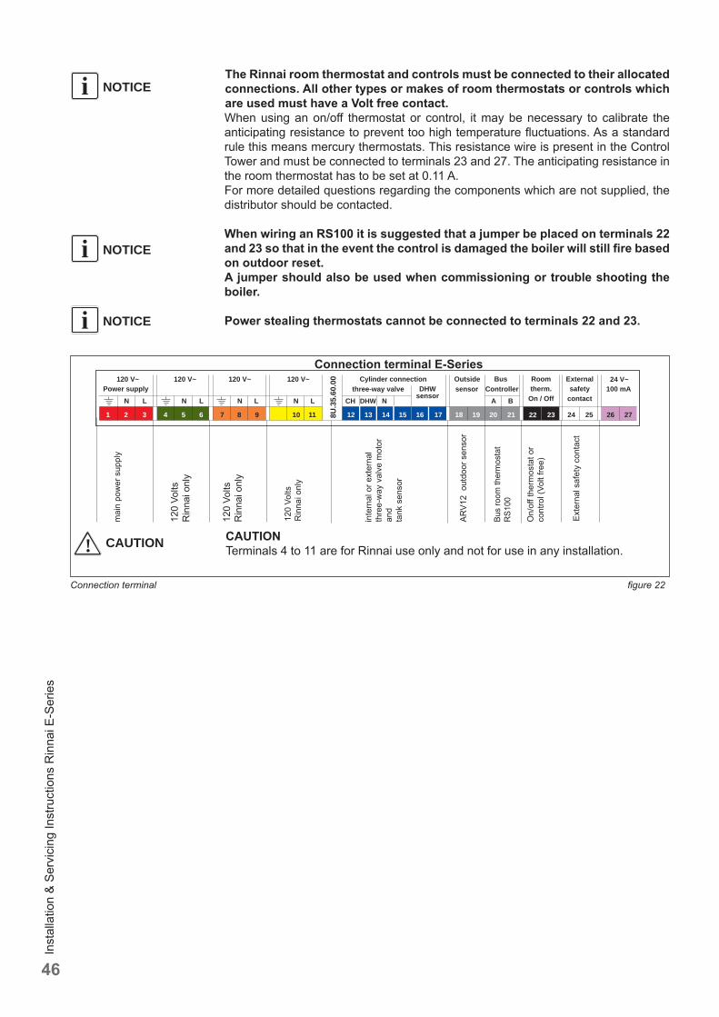
Inst
alla
tion
& Se
rvic
ing
Inst
ruct
ions
Rin
nai E
-Ser
ies
46
Connection terminal fi gure 22
NOTICEiThe Rinnai room thermostat and controls must be connected to their allocated connections. All other types or makes of room thermostats or controls which are used must have a Volt free contact.When using an on/off thermostat or control, it may be necessary to calibrate the anticipating resistance to prevent too high temperature fl uctuations. As a standard rule this means mercury thermostats. This resistance wire is present in the Control Tower and must be connected to terminals 23 and 27. The anticipating resistance in the room thermostat has to be set at 0.11 A.For more detailed questions regarding the components which are not supplied, the distributor should be contacted.
When wiring an RS100 it is suggested that a jumper be placed on terminals 22 and 23 so that in the event the control is damaged the boiler will still fi re based on outdoor reset. A jumper should also be used when commissioning or trouble shooting the boiler.
Power stealing thermostats cannot be connected to terminals 22 and 23.
NOTICEi
NOTICEi
Connection terminal E-Series
CAUTIONTerminals 4 to 11 are for Rinnai use only and not for use in any installation.! CAUTION
120 V~
10 11
120 V~ 120 V~ 120 V~Power supply
Cylinder connection
8U.3
5.60
.00 Outside
sensorBus
Controller24 V~
100 mA
1 2 3 4 5 6 7 8 9 12 13 14 15 16 17 18 19 20 21 22 23 24 25 26 27
N LN L N L N L CH DHW N A BDHW
sensorthree-way valve
Roomtherm.
On / Off
Externalsafety
contact
120
Volts
R
inna
i onl
y
mai
n po
wer
sup
ply
120
Volts
R
inna
i onl
y
120
Volts
Rin
nai o
nly
inte
rnal
or e
xter
nal
thre
e-w
ay v
alve
mot
or
and
tank
sen
sor
Bus
room
ther
mos
tat
RS1
00
On/
off t
herm
osta
t or
cont
rol (
Volt
free)
ARV1
2 o
utdo
or s
enso
r
Exte
rnal
saf
ety
cont
act
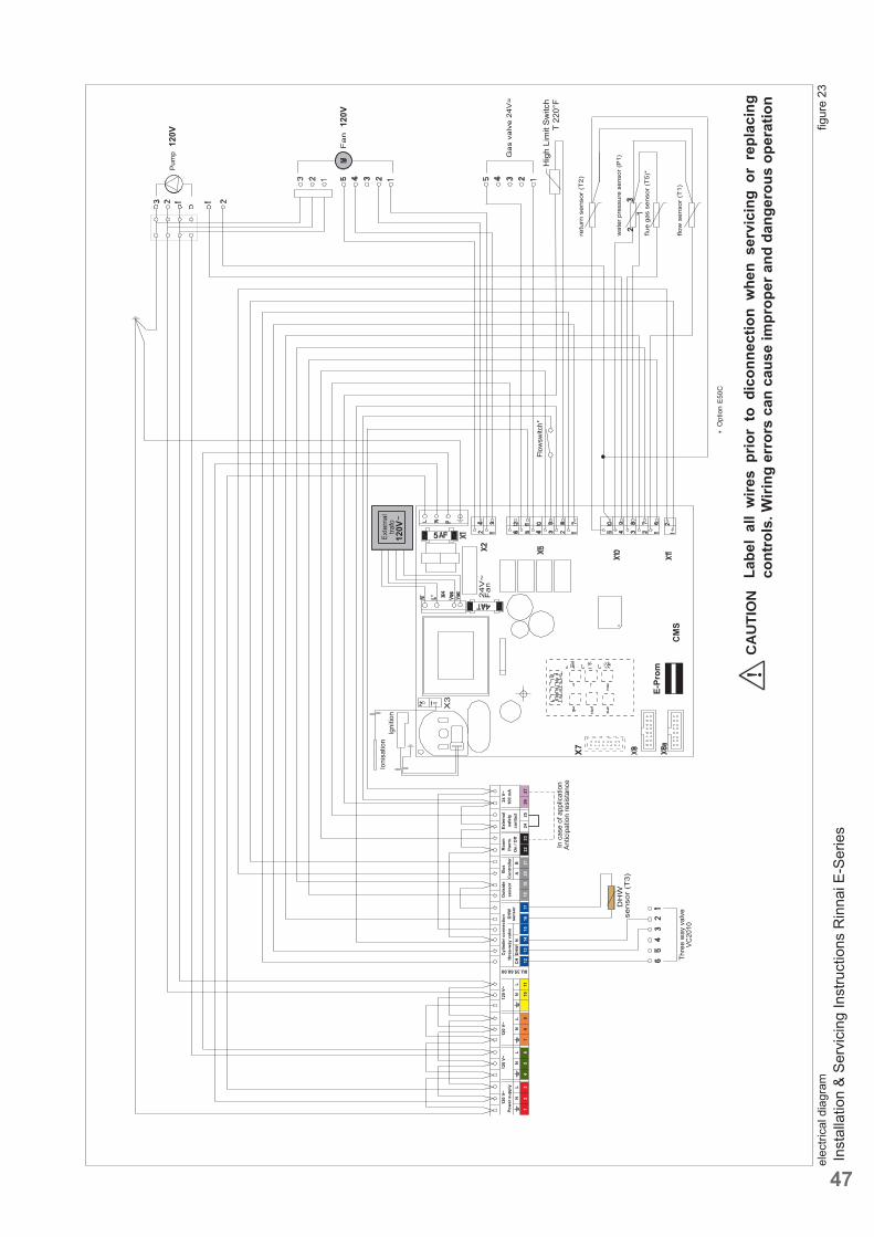
Inst
alla
tion
& Se
rvic
ing
Inst
ruct
ions
Rin
nai E
-Ser
ies
47
elec
trica
l dia
gram
fi g
ure
23
120V
Hig
h Li
mit
Sw
itch
T 22
0°F
120V
5
X7
E-Pr
om
Flow
switc
h*
120V
120
V~
1011
120
V~12
0 V~
120
V~Po
wer
sup
ply
Cyl
inde
r con
nect
ion
8U.35.60.00
Out
side
sens
orB
usC
ontr
olle
r24
V~
100
mA
12
34
56
78
912
1314
1516
1718
1920
2122
2324
2526
27
NL
NL
NL
NL
CH
DH
WN
AB
DH
Wse
nsor
thre
e-w
ay v
alve
Roo
mth
erm
.O
n / O
ff
Exte
rnal
safe
tyco
ntac
t
Labe
l al
l w
ires
prio
r to
dic
onne
ctio
n w
hen
serv
icin
g or
rep
laci
ng
cont
rols
. Wiri
ng e
rror
s ca
n ca
use
impr
oper
and
dan
gero
us o
pera
tion
!C
AU
TIO
N
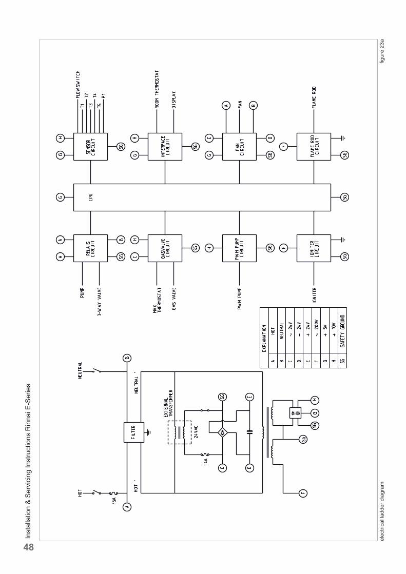
Inst
alla
tion
& Se
rvic
ing
Inst
ruct
ions
Rin
nai E
-Ser
ies
48
elec
trica
l lad
der d
iagr
am
fi gur
e 23
a
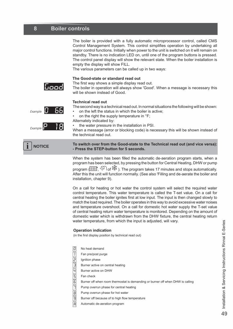
Inst
alla
tion
& Se
rvic
ing
Inst
ruct
ions
Rin
nai E
-Ser
ies
49
8 Boiler controls
The boiler is provided with a fully automatic microprocessor control, called CMS Control Management System. This control simplifi es operation by undertaking all major control functions. Initially when power to the unit is switched on it will remain on standby. There is no indication LED on, until one of the program buttons is pressed. The control panel display will show the relevant state. When the boiler installation is empty the display will show FILL.The various parameters can be called up in two ways:
The Good-state or standard read outThe fi rst way shows a simple display read out. The boiler in operation will always show 'Good'. When a message is necessary this will be shown instead of Good.
Technical read outThe second way is a technical read out. In normal situations the following will be shown:• on the left the status in which the boiler is active; • on the right the supply temperature in °F; Alternately indicated by:• the water pressure in the installation in PSI. When a message (error or blocking code) is necessary this will be shown instead of the technical read out.
To switch over from the Good-state to the Technical read out (and vice versa):- Press the STEP-button for 5 seconds.
When the system has been fi lled the automatic de-aeration program starts, when a program has been selected, by pressing the button for Central Heating, DHW or pump program ( , of ). The program takes 17 minutes and stops automatically. After this the unit will function normally. (See also 'Filling and de-aerate the boiler and installation, chapter 9).
On a call for heating or hot water the control system will select the required water control temperature. This water temperature is called the T-set value. On a call for central heating the boiler ignites fi rst at low input. The input is then changed slowly to match the load required. The boiler operates in this way to avoid excessive water noises and temperature overshoot. On a call for domestic hot water supply the T-set value of central heating return water temperature is monitored. Depending on the amount of domestic water which is withdrawn from the DHW fi xture, the central heating return water temperature, from which the input is adjusted, will vary.
Operation indication(in the fi rst display position by technical read out)
NOTICEi
12
No heat demand
Fan pre/post purge
Ignition phase
Burner active on central heating
Burner active on DHW
Fan check
Burner off when room thermostat is demanding or burner off when DHW is calling
Pump overrun phase for central heating
Pump overrun phase for hot water
Burner off because of to high fl ow temperature
Automatic de-aeration program
3456789A
0
Example
Example
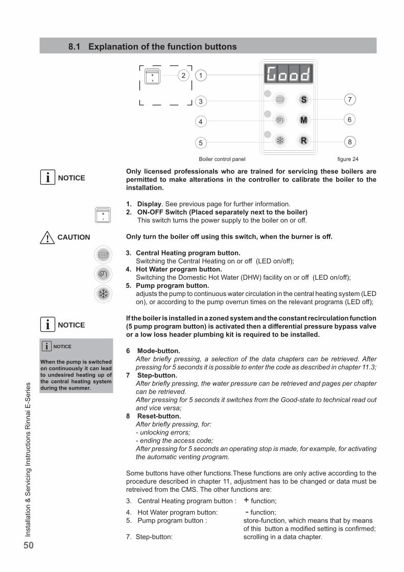
Inst
alla
tion
& Se
rvic
ing
Inst
ruct
ions
Rin
nai E
-Ser
ies
50
8.1 Explanation of the function buttons
NOTICEiOnly licensed professionals who are trained for servicing these boilers are permitted to make alterations in the controller to calibrate the boiler to the installation.
1. Display. See previous page for further information.2. ON-OFF Switch (Placed separately next to the boiler) This switch turns the power supply to the boiler on or off .
Only turn the boiler off using this switch, when the burner is off .
3. Central Heating program button. Switching the Central Heating on or off (LED on/off );4. Hot Water program button. Switching the Domestic Hot Water (DHW) facility on or off (LED on/off );5. Pump program button. adjusts the pump to continuous water circulation in the central heating system (LED
on), or according to the pump overrun times on the relevant programs (LED off );
If the boiler is installed in a zoned system and the constant recirculation function (5 pump program button) is activated then a diff erential pressure bypass valve or a low loss header plumbing kit is required to be installed.
6 Mode-button. After briefl y pressing, a selection of the data chapters can be retrieved. After
pressing for 5 seconds it is possible to enter the code as described in chapter 11.3;7 Step-button. After briefl y pressing, the water pressure can be retrieved and pages per chapter
can be retrieved. After pressing for 5 seconds it switches from the Good-state to technical read out
and vice versa;8 Reset-button. After briefl y pressing, for:
- unlocking errors; - ending the access code; After pressing for 5 seconds an operating stop is made, for example, for activating
the automatic venting program.
Some buttons have other functions.These functions are only active according to the procedure described in chapter 11, adjustment has to be changed or data must be retreived from the CMS. The other functions are:3. Central Heating program button : + function;4. Hot Water program button: - function;5. Pump program button : store-function, which means that by means of this button a modifi ed setting is confi rmed;7. Step-button: scrolling in a data chapter.
1
3
4
5
6
2
7
8
! CAUTION
Boiler control panel fi gure 24
When the pump is switched on continuously it can lead to undesired heating up of the central heating system during the summer.
NOTICEi
NOTICEi
Inst
alla
tion
& Se
rvic
ing
Inst
ruct
ions
Rin
nai E
-Ser
ies
51
9 Starting up: Filling and de-aerating the boiler and installation
CAUTIONObserve the following rules of safety:- All work on the unit must take place in a dry environment.- Rinnai units may never be in operation without their housing, except in connection
with maintenance or adjustments (see Chapter 12 and 13).- Never allow electrical or electronic components to come into contact with water.
NOTICECarry out the following tasks in connection with maintenance, etc. to an already-installed unit:- Shut down all programs- Close the gas shut off valve- Shut off the power at the main power switch- Close the service valves (system supply and return)NOTICETake note of the following when maintenance or adjustments are needed:- The unit must be able to function during these activities; for this reason, the unit’s
supply voltage, gas pressure and water pressure must be maintained. Ensure that this is not a source of potential danger during these activities.
Following maintenance or other activities; always check the installation of all parts through which gas fl ows (with bubble test using leak-search spray).
9.1 Requirements of the water system
Before fi lling the heating system, the complete system, including all zones, must be thoroughly cleaned and fl ushed to remove sediment. Flush until clean water runs free of sediment. Rinnai suggests using an approved system cleaner to fl ush the system, but not the boiler. Always use Rinnai approved antifreezes. See the list at the end of this chapter. Never use reverse osmosis, deionized, or distilled water for fi lling the heating system.
Do not use petroleum-based cleaning or sealing compounds in the boiler system. Damage of seals and gaskets in boiler and system could occur, resulting in property damage.
The central heating installation needs to be fi lled with potable water.
Use only potable water or approved glycol for fi lling the heating system. When the water hardness of the fi lling water exceeds > 10.5 gpg (200 mg/L) the water has to be treated until below the maximum value of 10.5 gpg (200 mg/L).The pH value of the installation water must be between 6.5 and 8.5.
Check the pH value using proper equipment or by having the water analyzed by a water treatment company.If pH diff ers from above, contact Rinnai engineering for further assistance.
Component or product damage as a result of failing to adhere to the water quality requirements will not be covered by the limited warranty.
! CAUTION
NOTICEi
NOTICEi
NOTICEi
! WARNING
! WARNING
! WARNING
Inst
alla
tion
& Se
rvic
ing
Inst
ruct
ions
Rin
nai E
-Ser
ies
52
Freeze protectionFreeze protection for new or existing systems must use glycol that is specially formulated for this purpose. This includes inhibitors, which prevent the glycol from attack the metallic components. This should be for multi-metallic components.Make certain to check that the system fl uid is correct for the glycol concentration and inhibitor level. The system should be tested at least once a year and as recommended by the producer of the glycol solution. The allowed maximum concentration is 50%.
Use only Rinnai approved inhibitors. See below for an approved list of inhibitors.
Use only inhibited propylene glycol solutions, which are specially formulated for central heating systems. Ethylene glycol is toxic and can attack gaskets and seals used in the boiler and system. Approved glycols are listed below.
Additives in the installation water are not permitted.
Approved antifreeze: • Rhomar RhoGard Mutli-Metal (AL safe) • Sentinel X500 (max. concentration 50%) • Noble Noburst AL • Fernox Alphi 11
Approved system cleaner: • Noble Noburst Hydronic System Cleaner • Fernox F3 Cleaner • Rhomar Hydro-Solv 9100 • Sentinel X400
The system cleaners from NoBurst, Rhomar, and Fernox are not to be used in the boiler. The boiler must be closed off (valved off ) from the rest of the system or not connected while the cleaners are in the system. The system should then be drained and then thoroughly fl ushed with clean water to remove all the system cleaner.
Approved inhibitors: • Rhomar Pro-tek 922 • Sentinel X100 • Noble Noburst AL inhibitor
9.2 Filling the heating system
For fi lling or topping off the installation you use the fi lling loop according to the following procedure:
1 Switch on the power supply;
2 The display will show FILL;
3 All functions off (heating , DHW and pump );
4 Push briefl y the 'STEP'-button: P XX (XX = water pressure in PSI);
5 Open the fi lling loop (Indication on display increases);
6 Fill up slowly to 16 to 18 PSI;
7 STOP appears on the display;
8 Close the fi lling loop;
9 De-aerate the complete installation, start at the lowest point;
10 Check the water pressure and if necessary top it up;
11 Close the fi lling loop;
12 Activate the functions in use (heating , DHW and/or pump );
NOTICEi
NOTICEi! WARNING
NOTICEi
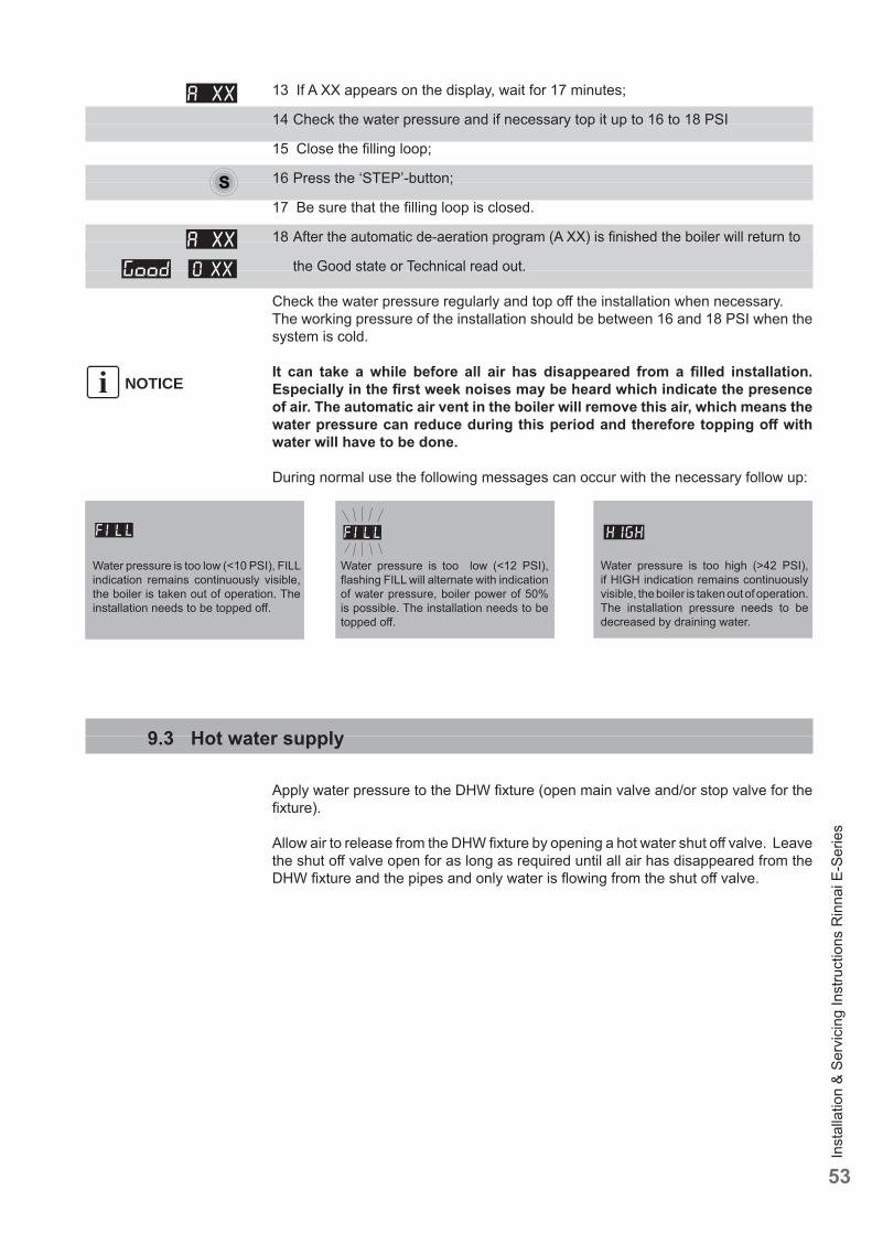
Inst
alla
tion
& Se
rvic
ing
Inst
ruct
ions
Rin
nai E
-Ser
ies
53
13 If A XX appears on the display, wait for 17 minutes;
14 Check the water pressure and if necessary top it up to 16 to 18 PSI
15 Close the fi lling loop;
16 Press the ‘STEP’-button;
17 Be sure that the fi lling loop is closed.
18 After the automatic de-aeration program (A XX) is fi nished the boiler will return to
the Good state or Technical read out.
Check the water pressure regularly and top off the installation when necessary. The working pressure of the installation should be between 16 and 18 PSI when the system is cold.
It can take a while before all air has disappeared from a fi lled installation. Especially in the fi rst week noises may be heard which indicate the presence of air. The automatic air vent in the boiler will remove this air, which means the water pressure can reduce during this period and therefore topping off with water will have to be done.
During normal use the following messages can occur with the necessary follow up:
NOTICEi
Water pressure is too low (<12 PSI), fl ashing FILL will alternate with indication of water pressure, boiler power of 50% is possible. The installation needs to be topped off .
Water pressure is too high (>42 PSI), if HIGH indication remains continuously visible, the boiler is taken out of operation. The installation pressure needs to be decreased by draining water.
Water pressure is too low (<10 PSI), FILL indication remains continuously visible, the boiler is taken out of operation. The installation needs to be topped off .
9.3 Hot water supply
Apply water pressure to the DHW fi xture (open main valve and/or stop valve for the fi xture).
Allow air to release from the DHW fi xture by opening a hot water shut off valve. Leave the shut off valve open for as long as required until all air has disappeared from the DHW fi xture and the pipes and only water is fl owing from the shut off valve.
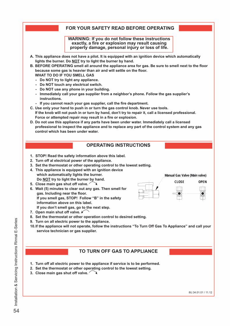
Inst
alla
tion
& Se
rvic
ing
Inst
ruct
ions
Rin
nai E
-Ser
ies
54
FOR YOUR SAFETY READ BEFORE OPERATING
WARNING: If you do not follow these instructions exactly, a fi re or explosion may result causing
property damage, personal injury or loss of life.
8U.34.01.01 / 11.12
A. This appliance does not have a pilot. It is equipped with an ignition device which automatically lights the burner. Do NOT try to light the burner by hand.
B. BEFORE OPERATING smell all around the appliance area for gas. Be sure to smell next to the fl oor because some gas is heavier than air and will settle on the fl oor.
WHAT TO DO IF YOU SMELL GAS - Do NOT try to light any appliance. - Do NOT touch any electrical switch. - Do NOT use any phone in your building. - Immediately call your gas supplier from a neighbor’s phone. Follow the gas supplier’s
instructions. - If you cannot reach your gas supplier, call the fi re department.
C. Use only your hand to push in or turn the gas control knob. Never use tools. If the knob will not push in or turn by hand, don’t try to repair it, call a licensed professional.
Force or attempted repair may result in a fi re or explosion. D. Do not use this appliance if any parts have been under water. Immediately call a licensed
professional to inspect the appliance and to replace any part of the control system and any gas control which has been under water.
OPERATING INSTRUCTIONS
1. STOP! Read the safety information above this label. 2. Turn off al electrical power of the appliance. 3. Set the thermostat or other operating control to the lowest setting. 4. This appliance is equipped with an ignition device
which automatically lights the burner. Do NOT try to light the burner by hand.
5. Close main gas shut off valve. 6. Wait (5) minutes to clear out any gas. Then smell for
gas. Including near the fl oor. If you smell gas, STOP! Follow “B” in the safety information above on this label. If you don’t smell gas, go to the next step.
7. Open main shut off valve. 8. Set the thermostat or other operation control to desired setting. 9. Turn on all electric power to the appliance. 10. If the appliance will not operate, follow the instructions “To Turn Off Gas To Appliance” and call your
service technician or gas supplier.
TO TURN OFF GAS TO APPLIANCE
1. Turn off all electric power to the appliance if service is to be performed. 2. Set the thermostat or other operating control to the lowest setting. 3. Close main gas shut off valve.
CLOSE
Manual Gas Valve (Main valve)
OPEN
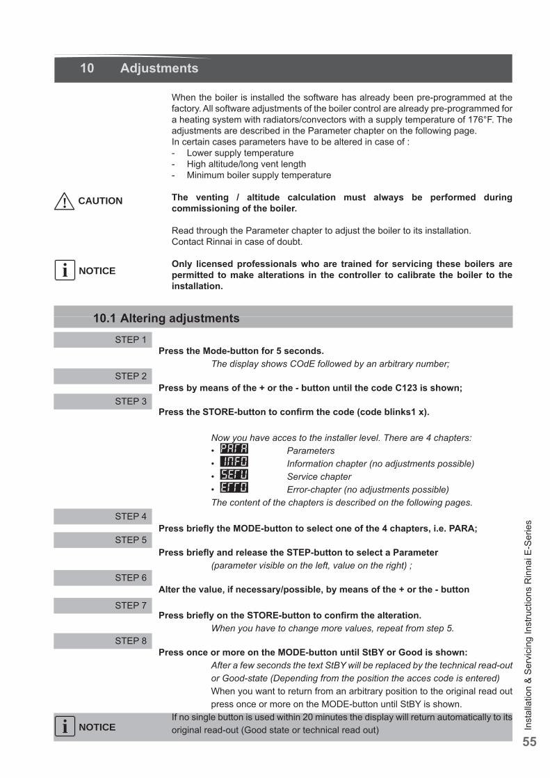
Inst
alla
tion
& Se
rvic
ing
Inst
ruct
ions
Rin
nai E
-Ser
ies
55
10 Adjustments
When the boiler is installed the software has already been pre-programmed at the factory. All software adjustments of the boiler control are already pre-programmed for a heating system with radiators/convectors with a supply temperature of 176°F. The adjustments are described in the Parameter chapter on the following page.In certain cases parameters have to be altered in case of :- Lower supply temperature- High altitude/long vent length- Minimum boiler supply temperature
The venting / altitude calculation must always be performed during commissioning of the boiler.
Read through the Parameter chapter to adjust the boiler to its installation.Contact Rinnai in case of doubt.
Only licensed professionals who are trained for servicing these boilers are permitted to make alterations in the controller to calibrate the boiler to the installation.
10.1 Altering adjustments
Press the Mode-button for 5 seconds. The display shows COdE followed by an arbitrary number;
Press by means of the + or the - button until the code C123 is shown;
Press the STORE-button to confi rm the code (code blinks1 x).
Now you have acces to the installer level. There are 4 chapters: • Parameters • Information chapter (no adjustments possible) • Service chapter • Error-chapter (no adjustments possible) The content of the chapters is described on the following pages.
Press briefl y the MODE-button to select one of the 4 chapters, i.e. PARA;
Press briefl y and release the STEP-button to select a Parameter (parameter visible on the left, value on the right) ;
Alter the value, if necessary/possible, by means of the + or the - button
Press briefl y on the STORE-button to confi rm the alteration. When you have to change more values, repeat from step 5.
Press once or more on the MODE-button until StBY or Good is shown: After a few seconds the text StBY will be replaced by the technical read-out
or Good-state (Depending from the position the acces code is entered) When you want to return from an arbitrary position to the original read out
press once or more on the MODE-button until StBY is shown.If no single button is used within 20 minutes the display will return automatically to its original read-out (Good state or technical read out)
NOTICEi
STEP 1
STEP 2
STEP 3
STEP 4
STEP 5
STEP 6
STEP 7
STEP 8
NOTICEi
! CAUTION
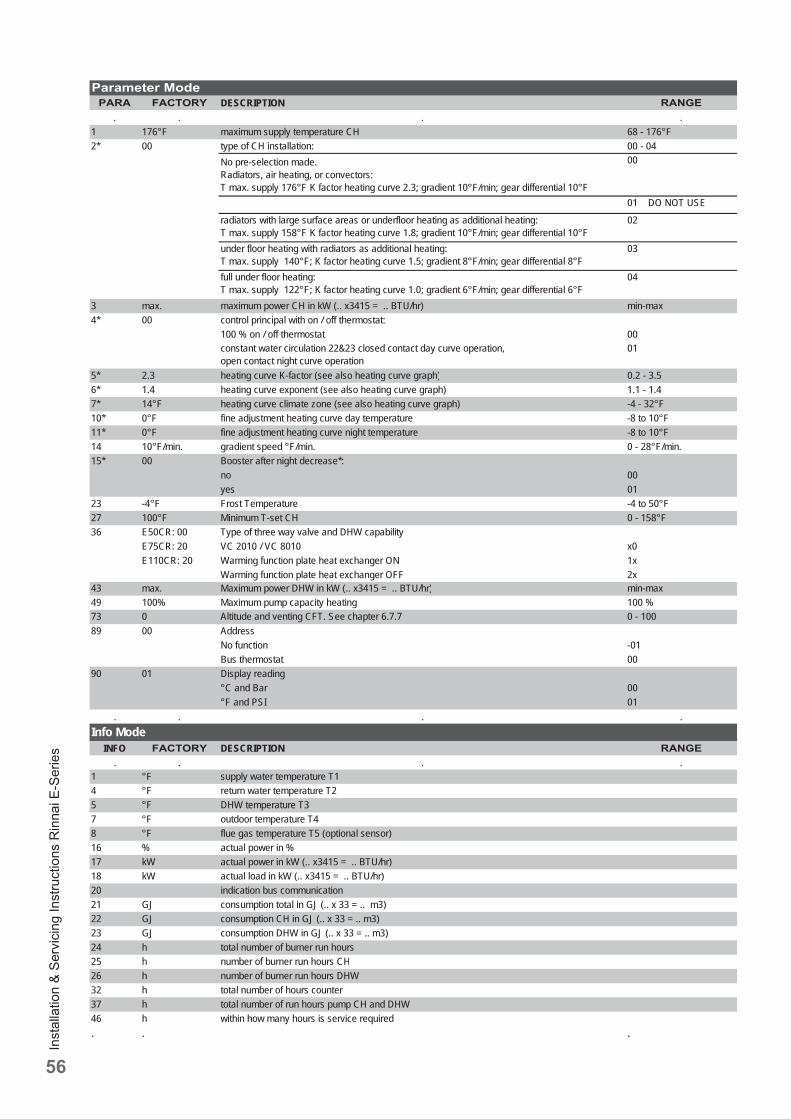
Inst
alla
tion
& Se
rvic
ing
Inst
ruct
ions
Rin
nai E
-Ser
ies
56
DESCRIPTION
1 176°F maximum supply temperature CH 68 - 176°F2* 00 type of CH installation: 00 - 04
No pre-selection made. Radiators, air heating, or convectors:T max. supply 176°F K factor heating curve 2.3; gradient 10°F/min; gear differential 10°F
00
01 DO NOT USE
radiators with large surface areas or underfloor heating as additional heating:T max. supply 158°F K factor heating curve 1.8; gradient 10°F/min; gear differential 10°F
02
under floor heating with radiators as additional heating:T max. supply 140°F; K factor heating curve 1.5; gradient 8°F/min; gear differential 8°F
03
full under floor heating:T max. supply 122°F; K factor heating curve 1.0; gradient 6°F/min; gear differential 6°F
04
3 max. maximum power CH in kW (.. x3415 = .. BTU/hr) min-max4* 00 control principal with on / off thermostat:
100 % on / off thermostat 00constant water circulation 22&23 closed contact day curve operation, open contact night curve operation
01
5* 2 3 h ti K f t ( l h ti h) 0 2 3 55* 2.3 heating curve K-factor (see also heating curve graph) 0.2 - 3.56* 1.4 heating curve exponent (see also heating curve graph) 1.1 - 1.47* 14°F heating curve climate zone (see also heating curve graph) -4 - 32°F10* 0°F fine adjustment heating curve day temperature -8 to 10°F11* 0°F fine adjustment heating curve night temperature -8 to 10°F14 10°F/min. gradient speed °F/min. 0 - 28°F/min.15* 00 Booster after night decrease*:
no 00yes 01
23 -4°F Frost Temperature -4 to 50°F27 100°F Minimum T-set CH 0 - 158°F36 E50CR: 00 Type of three way valve and DHW capability
E75CR: 20 VC 2010 / VC 8010 x0E110CR: 20 Warming function plate heat exchanger ON 1x
Warming function plate heat exchanger OFF 2x43 max. Maximum power DHW in kW (.. x3415 = .. BTU/hr) min-max49 100% Maximum pump capacity heating 100 %73 0 Altitude and venting CFT. See chapter 6.7.7 0 - 10089 00 Address
No function -01Bus thermostat 00
90 01 Display reading°C and Bar 00°F and PSI 01
. . . .Info Mode
INFO DESCRIPTION. . . .
1 °F supply water temperature T14 °F return water temperature T25 °F DHW temperature T37 °F outdoor temperature T48 °F flue gas temperature T5 (optional sensor)16 % actual power in %17 kW actual power in kW (.. x3415 = .. BTU/hr)18 kW actual load in kW (.. x3415 = .. BTU/hr)20 indication bus communication21 GJ consumption total in GJ (.. x 33 = .. m3)22 GJ consumption CH in GJ (.. x 33 = .. m3)23 GJ consumption DHW in GJ (.. x 33 = .. m3)24 h total number of burner run hours25 h b f b h CH25 h number of burner run hours CH26 h number of burner run hours DHW32 h total number of hours counter 37 h total number of run hours pump CH and DHW46 h within how many hours is service required. . .
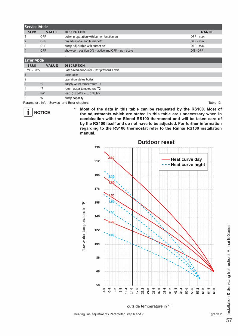
Inst
alla
tion
& Se
rvic
ing
Inst
ruct
ions
Rin
nai E
-Ser
ies
57
Service ModeSERV DESCRIPTION
1 OFF boiler in operation with burner function on OFF - max.2 OFF fan adjustable and burner off OFF - max.3 OFF pump adjustable with burner on OFF - max.4 OFF showroom position ON = active and OFF = non active ON - OFF. . . .Error Mode
ERRO DESCRIPTIONErr.L - Err.5 Last saved error until 5 last previous errors1 error code2 operation status boiler3 °F supply water temperature T14 °F return water temperature T25 kW load (.. x3415 = .. BTU/hr)6 % pump capacity
* Most of the data in this table can be requested by the RS100. Most of the adjustments which are stated in this table are unnecessary when in combination with the Rinnai RS100 thermostat and will be taken care of by the RS100 itself and do not have to be adjusted. For further information regarding to the RS100 thermostat refer to the Rinnai RS100 installation manual.
Parameter-, Info-, Service- and Error-chapters Table 12
NOTICEi
heating line adjustments Parameter Step 6 and 7 graph 2
outside temperature in °F
fl ow
wat
er te
mpe
ratu
re in
°F
Outdoor reset
Heat curve day Heat curve night
230
212
194
176
158
140
122
104
86
68
50
-4.0
-0.4
3.2
6.8
10.4
14.0
17.6
21.2
24.8
28.4
32.0
35.6
39.2
42.8
46.4
50.0
53.6
57.2
60.8
64.4
68.0
2.30
1.80
1.80
2.30
1.50
1.50
1.00
1.00
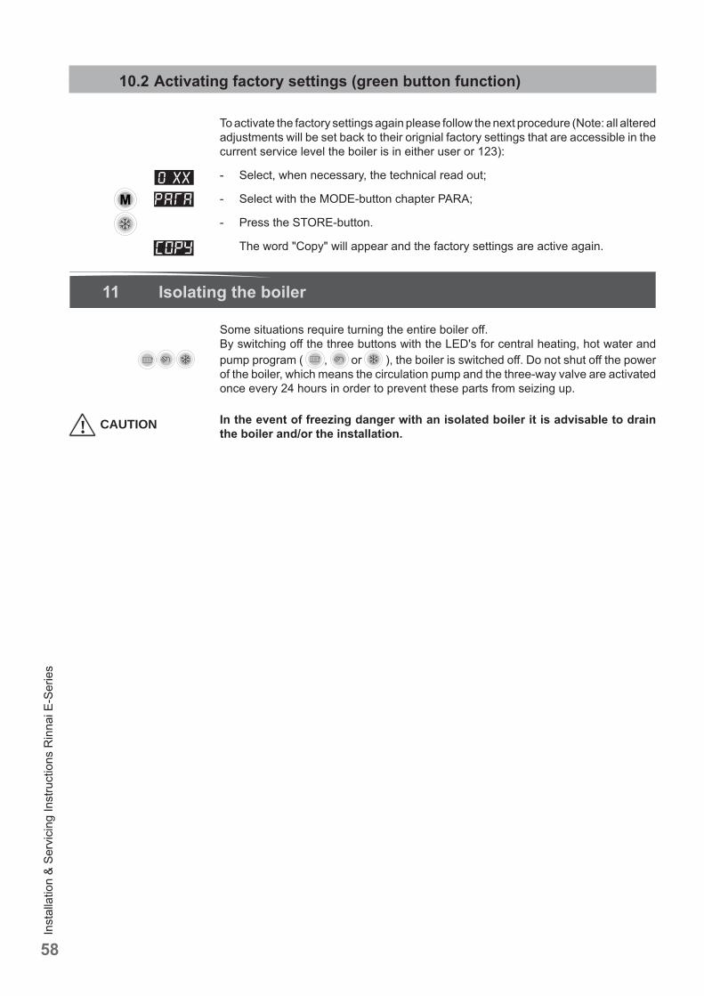
Inst
alla
tion
& Se
rvic
ing
Inst
ruct
ions
Rin
nai E
-Ser
ies
58
10.2 Activating factory settings (green button function)
To activate the factory settings again please follow the next procedure (Note: all altered adjustments will be set back to their orignial factory settings that are accessible in the current service level the boiler is in either user or 123):
- Select, when necessary, the technical read out;
- Select with the MODE-button chapter PARA;
- Press the STORE-button.
The word "Copy" will appear and the factory settings are active again.
11 Isolating the boiler
Some situations require turning the entire boiler off . By switching off the three buttons with the LED's for central heating, hot water and pump program ( , or ), the boiler is switched off . Do not shut off the power of the boiler, which means the circulation pump and the three-way valve are activated once every 24 hours in order to prevent these parts from seizing up.
In the event of freezing danger with an isolated boiler it is advisable to drain the boiler and/or the installation.! CAUTION
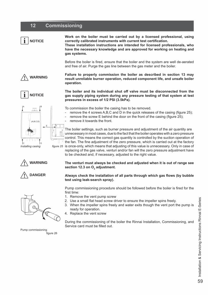
Inst
alla
tion
& Se
rvic
ing
Inst
ruct
ions
Rin
nai E
-Ser
ies
59
12 Commissioning
Work on the boiler must be carried out by a licensed professional, using correctly calibrated instruments with current test certifi cation.These installation instructions are intended for licensed professionals, who have the necessary knowledge and are approved for working on heating and gas systems.
Before the boiler is fi red, ensure that the boiler and the system are well de-aerated and free of air. Purge the gas line between the gas meter and the boiler.
Failure to properly commission the boiler as described in section 13 may result unreliable burner operation, reduced component life, and unsafe boiler operation.
The boiler and its individual shut off valve must be disconnected from the gas supply piping system during any pressure testing of that system at test pressures in excess of 1/2 PSI (3.5kPa).
To commission the boiler the casing has to be removed. - remove the 4 screws A,B,C and D in the quick releases of the casing (fi gure 25);- remove the screw E behind the door on the front of the casing (fi gure 25);- remove it towards the front.
The boiler settings, such as burner pressure and adjustment of the air quantity areunnecessary in most cases, due to the fact that the boiler operates with a zero pressurecontrol. This means the correct gas quantity is controlled by the suction operation ofthe fan. The fi ne adjustment of the zero pressure, which is carried out at the factory is once-only, which means that adjusting of this value is unnecessary. Only in case of replacing of the gas valve, venturi and/or fan will the zero pressure adjustment haveto be checked and, if necessary, adjusted to the right value.
The venturi must always be checked and adjusted when it is out of range see section 12.3 on O2 adjustment.
Always check the installation of all parts through which gas fl ows (by bubble test using leak-search spray).
Pump commissioning procedure should be followed before the boiler is fi red for the fi rst time:1. Remove the vent pump screw 2. Use a small fl at head screw driver to ensure the impeller spins freely.3. When the impeller spins freely and water exits though the vent port the pump is
ready for operation.4. Replace the vent screw
During the commissioning of the boiler the Rinnai Installation, Commissioning, and Service card must be fi lled out.
NOTICEi
NOTICEi
! WARNING
Installing casing fi gure 25
! DANGER
! WARNING
Pump commissioning fi gure 26
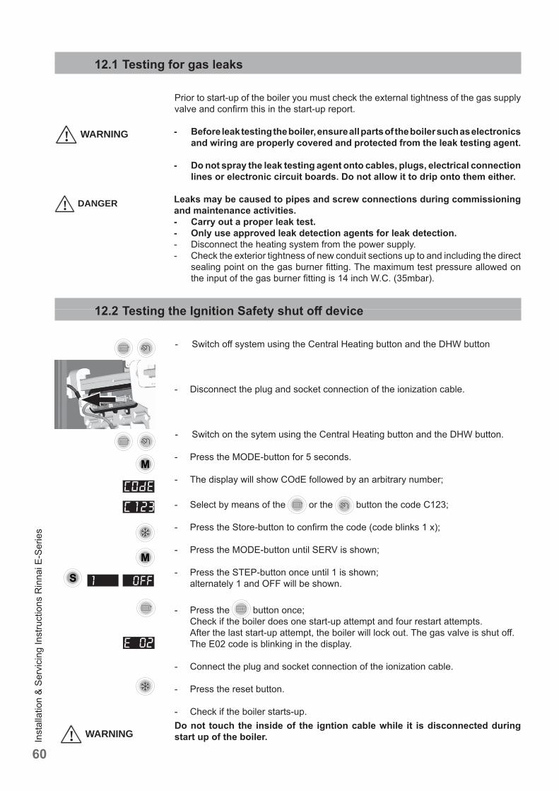
Inst
alla
tion
& Se
rvic
ing
Inst
ruct
ions
Rin
nai E
-Ser
ies
60
12.1 Testing for gas leaks
Prior to start-up of the boiler you must check the external tightness of the gas supply valve and confi rm this in the start-up report.
- Before leak testing the boiler, ensure all parts of the boiler such as electronics and wiring are properly covered and protected from the leak testing agent.
- Do not spray the leak testing agent onto cables, plugs, electrical connection lines or electronic circuit boards. Do not allow it to drip onto them either.
Leaks may be caused to pipes and screw connections during commissioning and maintenance activities.- Carry out a proper leak test.- Only use approved leak detection agents for leak detection.- Disconnect the heating system from the power supply.- Check the exterior tightness of new conduit sections up to and including the direct
sealing point on the gas burner fi tting. The maximum test pressure allowed on the input of the gas burner fi tting is 14 inch W.C. (35mbar).
12.2 Testing the Ignition Safety shut off device
- Switch off system using the Central Heating button and the DHW button
- Disconnect the plug and socket connection of the ionization cable.
- Switch on the sytem using the Central Heating button and the DHW button.
- Press the MODE-button for 5 seconds.
- The display will show COdE followed by an arbitrary number;
- Select by means of the or the button the code C123;
- Press the Store-button to confi rm the code (code blinks 1 x);
- Press the MODE-button until SERV is shown;
- Press the STEP-button once until 1 is shown; alternately 1 and OFF will be shown.
- Press the button once; Check if the boiler does one start-up attempt and four restart attempts. After the last start-up attempt, the boiler will lock out. The gas valve is shut off . The E02 code is blinking in the display.
- Connect the plug and socket connection of the ionization cable.
- Press the reset button.
- Check if the boiler starts-up.Do not touch the inside of the igntion cable while it is disconnected during start up of the boiler.
! DANGER
! WARNING
! WARNING
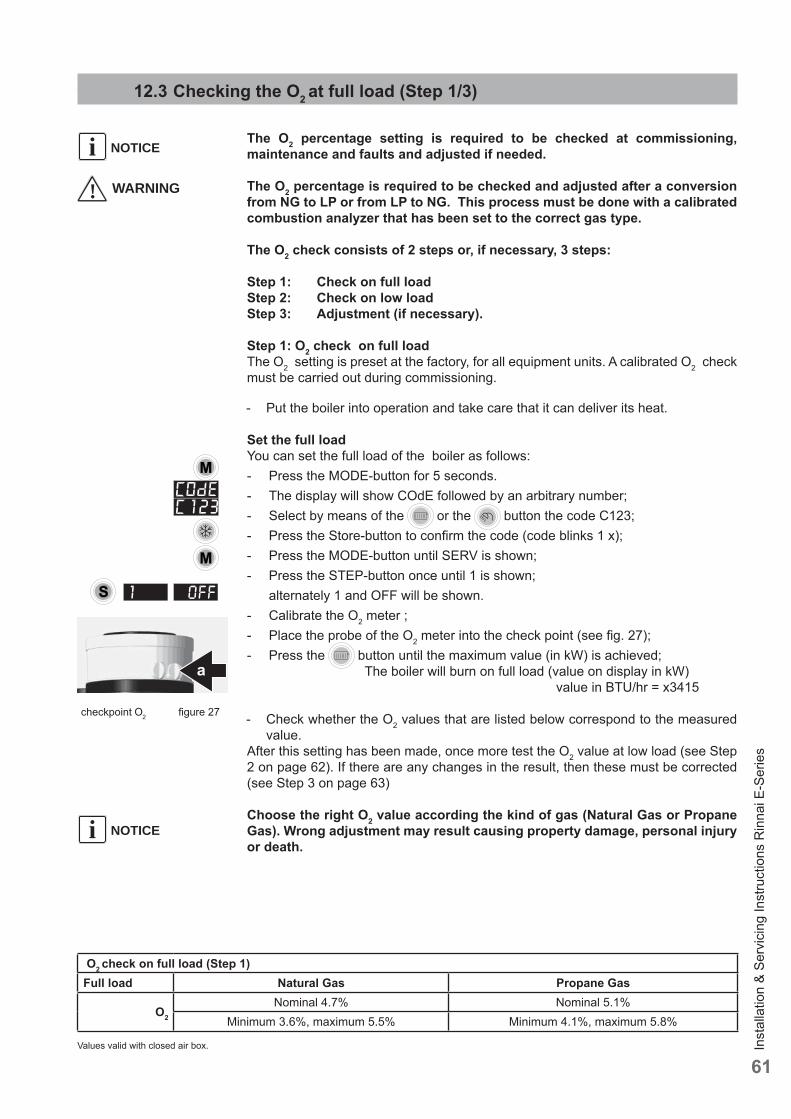
Inst
alla
tion
& Se
rvic
ing
Inst
ruct
ions
Rin
nai E
-Ser
ies
61
12.3 Checking the O2 at full load (Step 1/3)
The O2 percentage setting is required to be checked at commissioning, maintenance and faults and adjusted if needed.
The O2 percentage is required to be checked and adjusted after a conversion from NG to LP or from LP to NG. This process must be done with a calibrated combustion analyzer that has been set to the correct gas type.
The O2 check consists of 2 steps or, if necessary, 3 steps:
Step 1: Check on full loadStep 2: Check on low loadStep 3: Adjustment (if necessary).
Step 1: O2 check on full loadThe O2 setting is preset at the factory, for all equipment units. A calibrated O2 check must be carried out during commissioning.
- Put the boiler into operation and take care that it can deliver its heat.
Set the full loadYou can set the full load of the boiler as follows:- Press the MODE-button for 5 seconds. - The display will show COdE followed by an arbitrary number;- Select by means of the or the button the code C123;- Press the Store-button to confi rm the code (code blinks 1 x); - Press the MODE-button until SERV is shown;- Press the STEP-button once until 1 is shown; alternately 1 and OFF will be shown.- Calibrate the O2 meter ;- Place the probe of the O2 meter into the check point (see fi g. 27); - Press the button until the maximum value (in kW) is achieved; The boiler will burn on full load (value on display in kW) value in BTU/hr = x3415
- Check whether the O2 values that are listed below correspond to the measured value.
After this setting has been made, once more test the O2 value at low load (see Step 2 on page 62). If there are any changes in the result, then these must be corrected (see Step 3 on page 63)
Choose the right O2 value according the kind of gas (Natural Gas or Propane Gas). Wrong adjustment may result causing property damage, personal injury or death.
checkpoint O2 fi gure 27
NOTICEi
! WARNING
O2 check on full load (Step 1)Full load Natural Gas Propane Gas
O2
Nominal 4.7% Nominal 5.1%Minimum 3.6%, maximum 5.5% Minimum 4.1%, maximum 5.8%
Values valid with closed air box.
NOTICEi
a
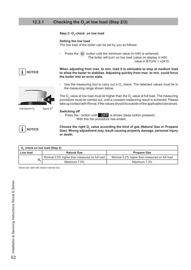
Inst
alla
tion
& Se
rvic
ing
Inst
ruct
ions
Rin
nai E
-Ser
ies
62
12.3.1 Checking the O2 at low load (Step 2/3)
Step 2: O2 check on low load
Setting the low loadThe low load of the boiler can be set by you as follows:
- Press the button until the minimum value (in kW) is achieved; The boiler will burn on low load (value on display in kW) value in BTU/hr = x3415
When adjusting from max. to min. load it is advisable to stop at medium load to allow the boiler to stabilize. Adjusting quickly from max. to min. could force the boiler into an error state.
- Use the measuring tool to carry out a O2 check. The detected values must lie in the measuring range shown below.
The O2 value at low load must lie higher than the O2 value at full load. The measuring procedure must be carried out, until a constant measuring result is achieved. Please take up contact with Rinnai, if the values should lie outside of the applicable tolerances.
Switching off - Press the - button until is shown (keep button pressed). With this the procedure has ended.
Choose the right O2 value according the kind of gas (Natural Gas or Propane Gas). Wrong adjustment may result causing property damage, personal injury or death.
NOTICEi
O2 check on low load (Step 2)Low load Natural Gas Propane Gas
O2
Minimal 0.5% higher than measured on full load Minimal 0.2% higher than measured on full loadMaximum 7.5% Maximum 7.3%
Values are valid with closed cover/air box.
checkpoint O2 fi gure 27
NOTICEi
a
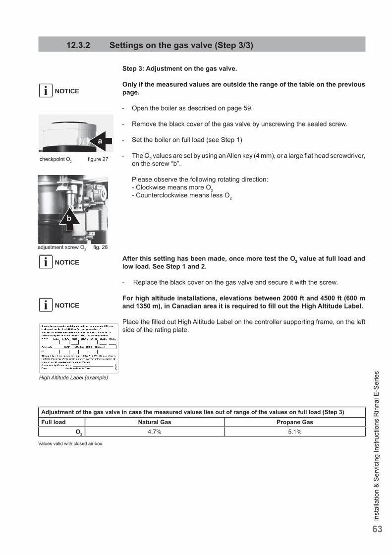
Inst
alla
tion
& Se
rvic
ing
Inst
ruct
ions
Rin
nai E
-Ser
ies
63
12.3.2 Settings on the gas valve (Step 3/3)
Step 3: Adjustment on the gas valve.
Only if the measured values are outside the range of the table on the previous page.
- Open the boiler as described on page 59.
- Remove the black cover of the gas valve by unscrewing the sealed screw.
- Set the boiler on full load (see Step 1)
- The O2 values are set by using an Allen key (4 mm), or a large fl at head screwdriver, on the screw “b”.
Please observe the following rotating direction: - Clockwise means more O2 - Counterclockwise means less O2
After this setting has been made, once more test the O2 value at full load and low load. See Step 1 and 2.
- Replace the black cover on the gas valve and secure it with the screw.
For high altitude installations, elevations between 2000 ft and 4500 ft (600 m and 1350 m), in Canadian area it is required to fi ll out the High Altitude Label.
Place the fi lled out High Altitude Label on the controller supporting frame, on the left side of the rating plate.
checkpoint O2 fi gure 27
adjustment screw O2 fi g. 28
NOTICEi
Adjustment of the gas valve in case the measured values lies out of range of the values on full load (Step 3)Full load Natural Gas Propane Gas
O2 4.7% 5.1%
Values valid with closed air box.
NOTICEi
b
NOTICEi
a
High Altitude Label (example)
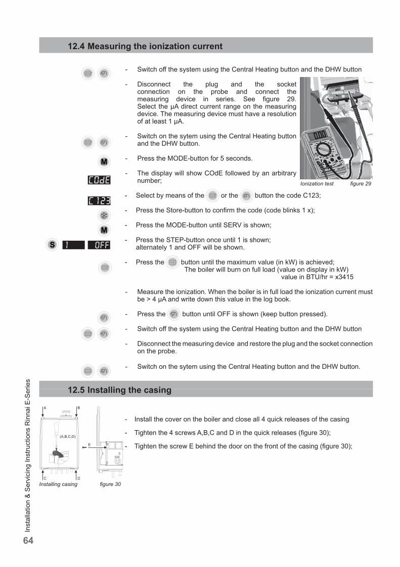
Inst
alla
tion
& Se
rvic
ing
Inst
ruct
ions
Rin
nai E
-Ser
ies
64
Installing casing fi gure 30
12.4 Measuring the ionization current
- Switch off the system using the Central Heating button and the DHW button
- Disconnect the plug and the socket connection on the probe and connect the measuring device in series. See fi gure 29.Select the μA direct current range on the measuring device. The measuring device must have a resolution of at least 1 μA.
- Switch on the sytem using the Central Heating button and the DHW button.
- Press the MODE-button for 5 seconds.
- The display will show COdE followed by an arbitrary number;
- Select by means of the or the button the code C123;
- Press the Store-button to confi rm the code (code blinks 1 x);
- Press the MODE-button until SERV is shown;
- Press the STEP-button once until 1 is shown; alternately 1 and OFF will be shown.
- Press the button until the maximum value (in kW) is achieved; The boiler will burn on full load (value on display in kW) value in BTU/hr = x3415
- Measure the ionization. When the boiler is in full load the ionization current must be > 4 μA and write down this value in the log book.
- Press the button until OFF is shown (keep button pressed).
- Switch off the system using the Central Heating button and the DHW button
- Disconnect the measuring device and restore the plug and the socket connection on the probe.
- Switch on the sytem using the Central Heating button and the DHW button.
12.5 Installing the casing
- Install the cover on the boiler and close all 4 quick releases of the casing
- Tighten the 4 screws A,B,C and D in the quick releases (fi gure 30);
- Tighten the screw E behind the door on the front of the casing (fi gure 30);
Ionization test fi gure 29
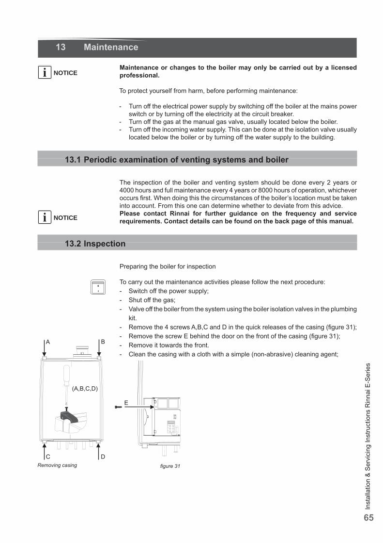
Inst
alla
tion
& Se
rvic
ing
Inst
ruct
ions
Rin
nai E
-Ser
ies
65
13 Maintenance
Maintenance or changes to the boiler may only be carried out by a licensed professional.
To protect yourself from harm, before performing maintenance:
- Turn off the electrical power supply by switching off the boiler at the mains power switch or by turning off the electricity at the circuit breaker.
- Turn off the gas at the manual gas valve, usually located below the boiler.- Turn off the incoming water supply. This can be done at the isolation valve usually
located below the boiler or by turning off the water supply to the building.
13.1 Periodic examination of venting systems and boiler
The inspection of the boiler and venting system should be done every 2 years or 4000 hours and full maintenance every 4 years or 8000 hours of operation, whichever occurs fi rst. When doing this the circumstances of the boiler’s location must be taken into account. From this one can determine whether to deviate from this advice. Please contact Rinnai for further guidance on the frequency and service requirements. Contact details can be found on the back page of this manual.
13.2 Inspection
Preparing the boiler for inspection
To carry out the maintenance activities please follow the next procedure:- Switch off the power supply;- Shut off the gas;- Valve off the boiler from the system using the boiler isolation valves in the plumbing
kit.- Remove the 4 screws A,B,C and D in the quick releases of the casing (fi gure 31);- Remove the screw E behind the door on the front of the casing (fi gure 31);- Remove it towards the front.- Clean the casing with a cloth with a simple (non-abrasive) cleaning agent;
NOTICEi
NOTICEi
Removing casing fi gure 31
Inst
alla
tion
& Se
rvic
ing
Inst
ruct
ions
Rin
nai E
-Ser
ies
66
13.2.1 Visual inspection for general signs of corrosion
- Check all gas and water pipes for signs of corrosion.- Replace any pipes that are corroded.
13.2.2 Measuring the ionization current
See subsection 12.5 “Measuring the ionization current".
13.2.3 Measuring the inlet gas pressure
See subsection 6.4.1 and .2 “Gas connection with natural gas" and "Gas connection with propane”.
13.2.4 Testing for gas leaks
See subsection 12.1 “Testing for gas leaks”.
13.2.5 Carrying out a pressure test of the heating system
See chapter 9.2 “Filling the heating system”.
13.2.6 Checking venting systems
Check the following points:- Is the prescribed combustion air/fl ue system used?- Have the instructions for confi guring the fl ue system as specifi ed in the relevant Installation instruction for the fl ue gas system been observed?- Check air intake and/or air fi lter and fl ue gas for obstruction, pollution or damage.
When an air fi lter is used the air fi lter must be replaced yearly on boilers operating in normal circumstances.The conditions (eg. supply air quality) in which the boiler is installed should be taken into account. This will show whether the frequency of replacement should be reduced or increased. If in doubt, contact RINNAI.
NOTICEi
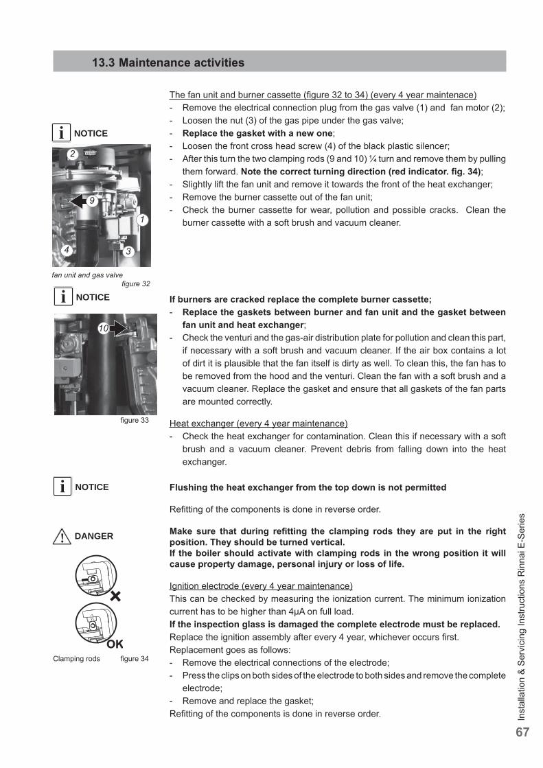
Inst
alla
tion
& Se
rvic
ing
Inst
ruct
ions
Rin
nai E
-Ser
ies
67
13.3 Maintenance activities
The fan unit and burner cassette (fi gure 32 to 34) (every 4 year maintenace)- Remove the electrical connection plug from the gas valve (1) and fan motor (2);- Loosen the nut (3) of the gas pipe under the gas valve;- Replace the gasket with a new one;- Loosen the front cross head screw (4) of the black plastic silencer;- After this turn the two clamping rods (9 and 10) ¼ turn and remove them by pulling
them forward. Note the correct turning direction (red indicator. fi g. 34);- Slightly lift the fan unit and remove it towards the front of the heat exchanger;- Remove the burner cassette out of the fan unit;- Check the burner cassette for wear, pollution and possible cracks. Clean the
burner cassette with a soft brush and vacuum cleaner.
If burners are cracked replace the complete burner cassette;- Replace the gaskets between burner and fan unit and the gasket between
fan unit and heat exchanger;- Check the venturi and the gas-air distribution plate for pollution and clean this part,
if necessary with a soft brush and vacuum cleaner. If the air box contains a lot of dirt it is plausible that the fan itself is dirty as well. To clean this, the fan has to be removed from the hood and the venturi. Clean the fan with a soft brush and a vacuum cleaner. Replace the gasket and ensure that all gaskets of the fan parts are mounted correctly.
Heat exchanger (every 4 year maintenance)- Check the heat exchanger for contamination. Clean this if necessary with a soft
brush and a vacuum cleaner. Prevent debris from falling down into the heat exchanger.
Flushing the heat exchanger from the top down is not permitted
Refi tting of the components is done in reverse order.
Make sure that during refi tting the clamping rods they are put in the right position. They should be turned vertical.If the boiler should activate with clamping rods in the wrong position it will cause property damage, personal injury or loss of life.
Ignition electrode (every 4 year maintenance)This can be checked by measuring the ionization current. The minimum ionization current has to be higher than 4μA on full load.If the inspection glass is damaged the complete electrode must be replaced.Replace the ignition assembly after every 4 year, whichever occurs fi rst.Replacement goes as follows:- Remove the electrical connections of the electrode;- Press the clips on both sides of the electrode to both sides and remove the complete
electrode;- Remove and replace the gasket;Refi tting of the components is done in reverse order.
fan unit and gas valve fi gure 32
NOTICEi
NOTICEi
NOTICEi
! DANGER
fi gure 33
Clamping rods fi gure 34
10
1
2
3
9
4
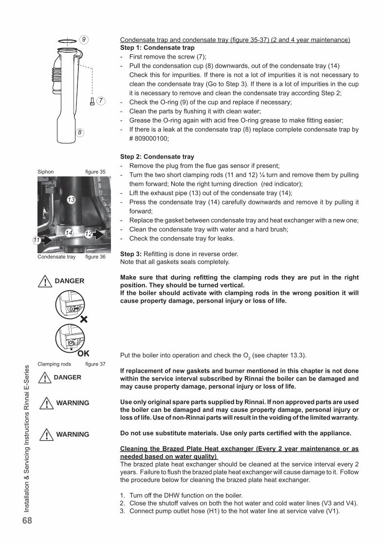
Inst
alla
tion
& Se
rvic
ing
Inst
ruct
ions
Rin
nai E
-Ser
ies
68
Condensate trap and condensate tray (fi gure 35-37) (2 and 4 year maintenance)Step 1: Condensate trap- First remove the screw (7);- Pull the condensation cup (8) downwards, out of the condensate tray (14) Check this for impurities. If there is not a lot of impurities it is not necessary to
clean the condensate tray (Go to Step 3). If there is a lot of impurities in the cup it is necessary to remove and clean the condensate tray according Step 2;
- Check the O-ring (9) of the cup and replace if necessary;- Clean the parts by fl ushing it with clean water;- Grease the O-ring again with acid free O-ring grease to make fi tting easier;- If there is a leak at the condensate trap (8) replace complete condensate trap by
# 809000100;
Step 2: Condensate tray- Remove the plug from the fl ue gas sensor if present;- Turn the two short clamping rods (11 and 12) ¼ turn and remove them by pulling
them forward; Note the right turning direction (red indicator);- Lift the exhaust pipe (13) out of the condensate tray (14);- Press the condensate tray (14) carefully downwards and remove it by pulling it
forward;- Replace the gasket between condensate tray and heat exchanger with a new one;- Clean the condensate tray with water and a hard brush;- Check the condensate tray for leaks.
Step 3: Refi tting is done in reverse order.Note that all gaskets seals completely.
Make sure that during refi tting the clamping rods they are put in the right position. They should be turned vertical.If the boiler should activate with clamping rods in the wrong position it will cause property damage, personal injury or loss of life.
Put the boiler into operation and check the O2 (see chapter 13.3).
If replacement of new gaskets and burner mentioned in this chapter is not done within the service interval subscribed by Rinnai the boiler can be damaged and may cause property damage, personal injury or loss of life.
Use only original spare parts supplied by Rinnai. If non approved parts are used the boiler can be damaged and may cause property damage, personal injury or loss of life. Use of non-Rinnai parts will result in the voiding of the limited warranty.
Do not use substitute materials. Use only parts certifi ed with the appliance.
Cleaning the Brazed Plate Heat exchanger (Every 2 year maintenance or as needed based on water quality) The brazed plate heat exchanger should be cleaned at the service interval every 2 years. Failure to fl ush the brazed plate heat exchanger will cause damage to it. Follow the procedure below for cleaning the brazed plate heat exchanger.
1. Turn off the DHW function on the boiler.2. Close the shutoff valves on both the hot water and cold water lines (V3 and V4).3. Connect pump outlet hose (H1) to the hot water line at service valve (V1).
! DANGER
! DANGER
Clamping rods fi gure 37
Condensate tray fi gure 36
Siphon fi gure 35
8
9
7
! WARNING
1112
13
14
! WARNING
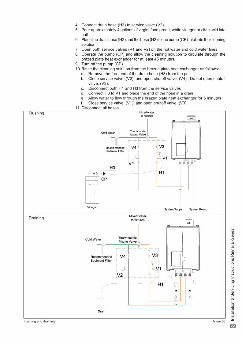
Inst
alla
tion
& Se
rvic
ing
Inst
ruct
ions
Rin
nai E
-Ser
ies
69
4. Connect drain hose (H3) to service valve (V2).5. Pour approximately 4 gallons of virgin, food grade, white vinegar or citric acid into
pail.6. Place the drain hose (H3) and the hose (H2) to the pump (CP) inlet into the cleaning
solution.7. Open both service valves (V1 and V2) on the hot water and cold water lines.8. Operate the pump (CP) and allow the cleaning solution to circulate through the
brazed plate heat exchanger for at least 45 minutes.9. Turn off the pump (CP).10. Rinse the cleaning solution from the brazed plate heat exchanger as follows: a. Remove the free end of the drain hose (H3) from the pail b. Close service valve, (V2), and open shutoff valve, (V4). Do not open shutoff
valve, (V3). c. Disconnect both H1 and H3 from the service valves d. Connect H3 to V1 and place the end of the hose in a drain e. Allow water to fl ow through the brazed plate heat exchanger for 5 minutes f. Close service valve, (V1), and open shutoff valve, (V3).11. Disconnect all hoses.
Flushing and draining fi gure 38
Flushing
Draining
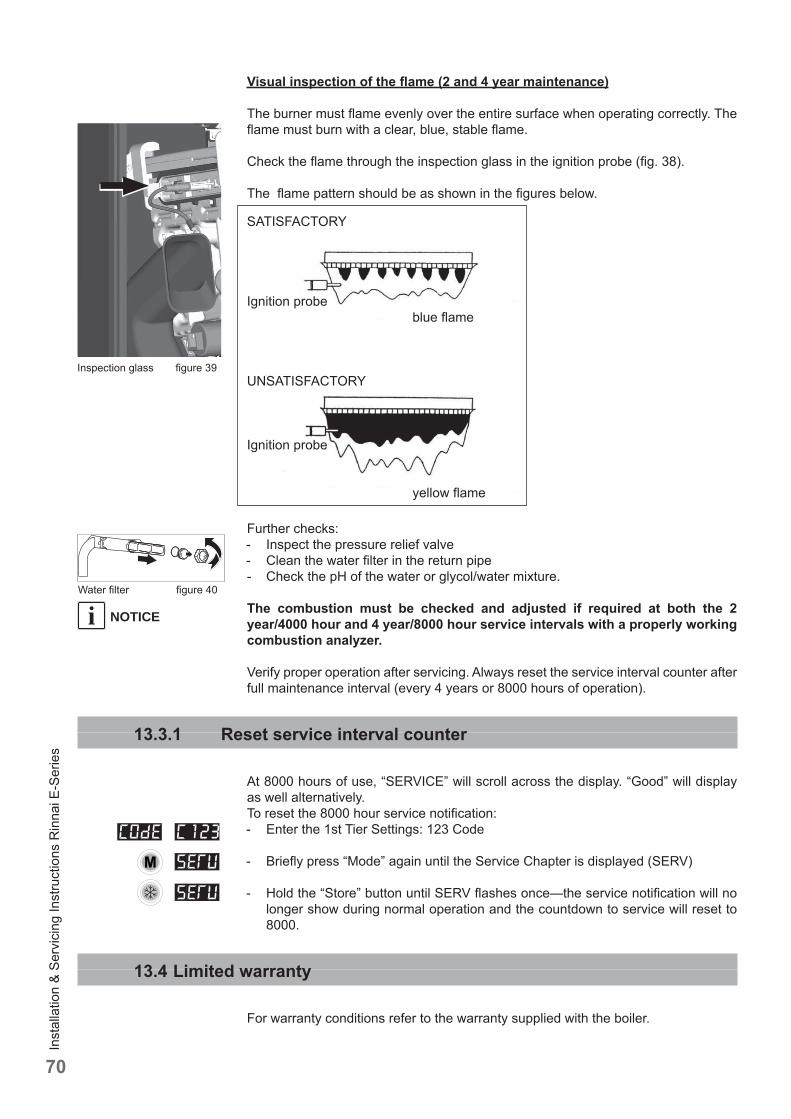
Inst
alla
tion
& Se
rvic
ing
Inst
ruct
ions
Rin
nai E
-Ser
ies
70
Visual inspection of the fl ame (2 and 4 year maintenance)
The burner must fl ame evenly over the entire surface when operating correctly. The fl ame must burn with a clear, blue, stable fl ame.
Check the fl ame through the inspection glass in the ignition probe (fi g. 38).
The fl ame pattern should be as shown in the fi gures below.
Further checks:- Inspect the pressure relief valve- Clean the water fi lter in the return pipe- Check the pH of the water or glycol/water mixture.
The combustion must be checked and adjusted if required at both the 2 year/4000 hour and 4 year/8000 hour service intervals with a properly working combustion analyzer.
Verify proper operation after servicing. Always reset the service interval counter after full maintenance interval (every 4 years or 8000 hours of operation).
13.3.1 Reset service interval counter
At 8000 hours of use, “SERVICE” will scroll across the display. “Good” will display as well alternatively.To reset the 8000 hour service notifi cation: - Enter the 1st Tier Settings: 123 Code
- Briefl y press “Mode” again until the Service Chapter is displayed (SERV)
- Hold the “Store” button until SERV fl ashes once—the service notifi cation will no longer show during normal operation and the countdown to service will reset to 8000.
13.4 Limited warranty
For warranty conditions refer to the warranty supplied with the boiler.
Inspection glass fi gure 39
NOTICEiWater fi lter fi gure 40
SATISFACTORY
Ignition probe blue fl ame
UNSATISFACTORY
Ignition probe
yellow fl ame
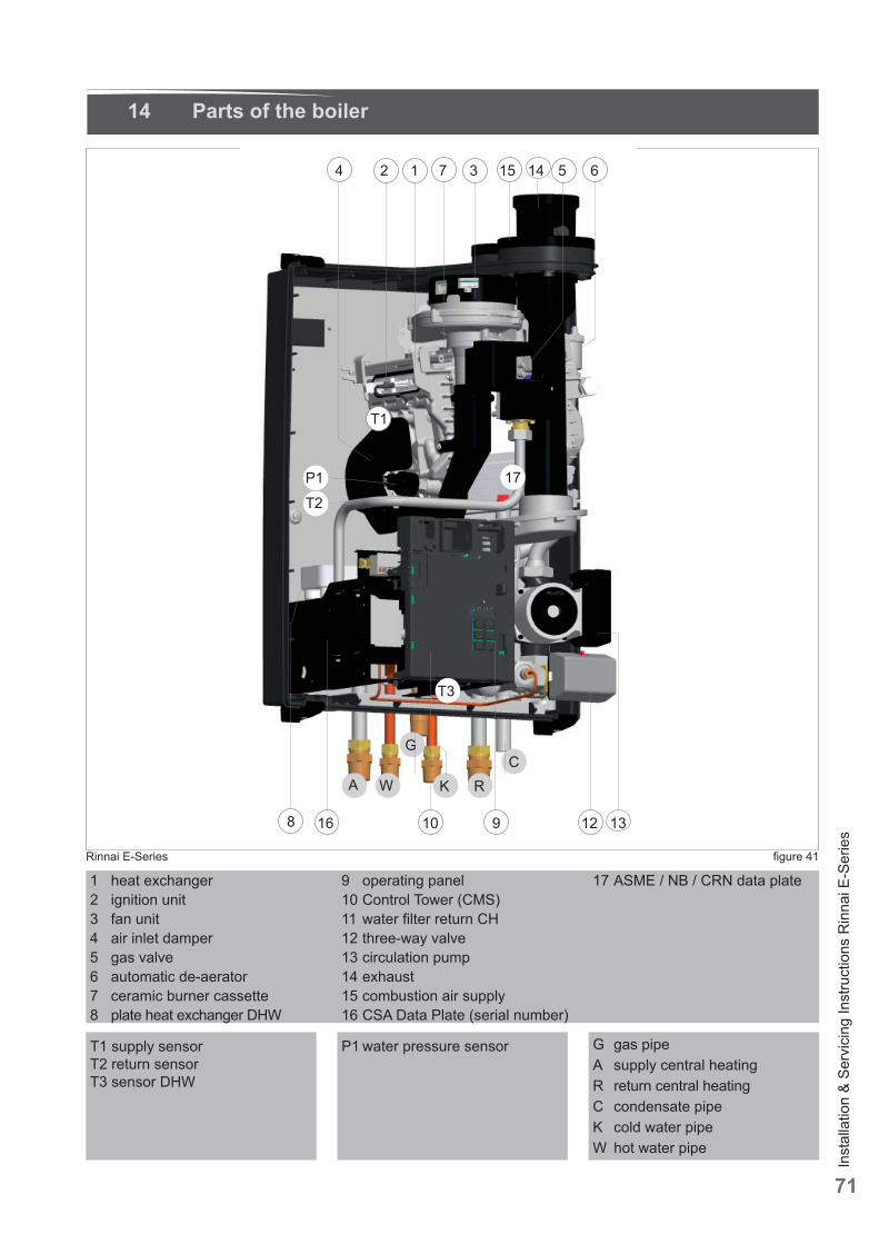
Inst
alla
tion
& Se
rvic
ing
Inst
ruct
ions
Rin
nai E
-Ser
ies
71
1 heat exchanger 2 ignition unit3 fan unit4 air inlet damper5 gas valve6 automatic de-aerator7 ceramic burner cassette8 plate heat exchanger DHW
9 operating panel10 Control Tower (CMS)11 water fi lter return CH12 three-way valve13 circulation pump14 exhaust15 combustion air supply16 CSA Data Plate (serial number)
T1 supply sensorT2 return sensorT3 sensor DHW
Rinnai E-Series fi gure 41
17 ASME / NB / CRN data plate
P1 water pressure sensor
14 Parts of the boiler
G gas pipeA supply central heatingR return central heatingC condensate pipeK cold water pipeW hot water pipe
4 2 1 3 15 514 6
CW
G
T1
7
T3
K RA
8 12 1316 910
17
T2P1
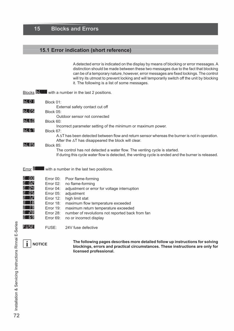
Inst
alla
tion
& Se
rvic
ing
Inst
ruct
ions
Rin
nai E
-Ser
ies
72
NOTICEi
15 Blocks and Errors
15.1 Error indication (short reference)
A detected error is indicated on the display by means of blocking or error messages. A distinction should be made between these two messages due to the fact that blocking can be of a temporary nature, however, error messages are fi xed lockings. The control will try its utmost to prevent locking and will temporarily switch off the unit by blocking it. The following is a list of some messages.
Blocks with a number in the last 2 positions.
Block 01: External safety contact cut off
Block 05: Outdoor sensor not connected
Block 60: Incorrect parameter setting of the minimum or maximum power.
Block 67: A T has been detected between fl ow and return sensor whereas the burner is not in operation. After the T has disappeared the block will clear.
Block 85: The control has not detected a water fl ow. The venting cycle is started. If during this cycle water fl ow is detected, the venting cycle is ended and the burner is released.
Error with a number in the last two positions.
Error 00: Poor fl ame-forming Error 02: no fl ame-forming Error 04: adjustment or error for voltage interruption Error 05: adjustment Error 12: high limit stat Error 18: maximum fl ow temperature exceeded Error 19: maximum return temperature exceeded Error 28: number of revolutions not reported back from fan Error 69: no or incorrect display
FUSE: 24V fuse defective
The following pages describes more detailed follow up instructions for solving blockings, errors and practical circumstances. These instructions are only for licensed professional.
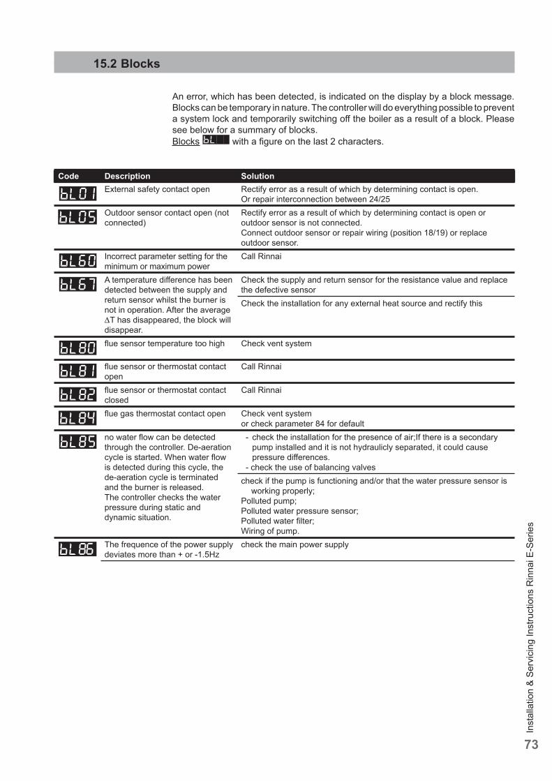
Inst
alla
tion
& Se
rvic
ing
Inst
ruct
ions
Rin
nai E
-Ser
ies
73
15.2 Blocks
An error, which has been detected, is indicated on the display by a block message. Blocks can be temporary in nature. The controller will do everything possible to prevent a system lock and temporarily switching off the boiler as a result of a block. Please see below for a summary of blocks.Blocks with a fi gure on the last 2 characters.
Code Description SolutionExternal safety contact open Rectify error as a result of which by determining contact is open.
Or repair interconnection between 24/25Outdoor sensor contact open (not connected)
Rectify error as a result of which by determining contact is open or outdoor sensor is not connected.Connect outdoor sensor or repair wiring (position 18/19) or replace outdoor sensor.
Incorrect parameter setting for the minimum or maximum power
Call Rinnai
A temperature diff erence has been detected between the supply and return sensor whilst the burner is not in operation. After the average T has disappeared, the block will disappear.
Check the supply and return sensor for the resistance value and replace the defective sensorCheck the installation for any external heat source and rectify this
fl ue sensor temperature too high Check vent system
fl ue sensor or thermostat contact open
Call Rinnai
fl ue sensor or thermostat contact closed
Call Rinnai
fl ue gas thermostat contact open Check vent system or check parameter 84 for default
no water fl ow can be detected through the controller. De-aeration cycle is started. When water fl ow is detected during this cycle, the de-aeration cycle is terminated and the burner is released.The controller checks the water pressure during static and dynamic situation.
- check the installation for the presence of air;If there is a secondary pump installed and it is not hydraulicly separated, it could cause pressure diff erences.
- check the use of balancing valvescheck if the pump is functioning and/or that the water pressure sensor is
working properly;Polluted pump;Polluted water pressure sensor;Polluted water fi lter;Wiring of pump.
The frequence of the power supply deviates more than + or -1.5Hz
check the main power supply
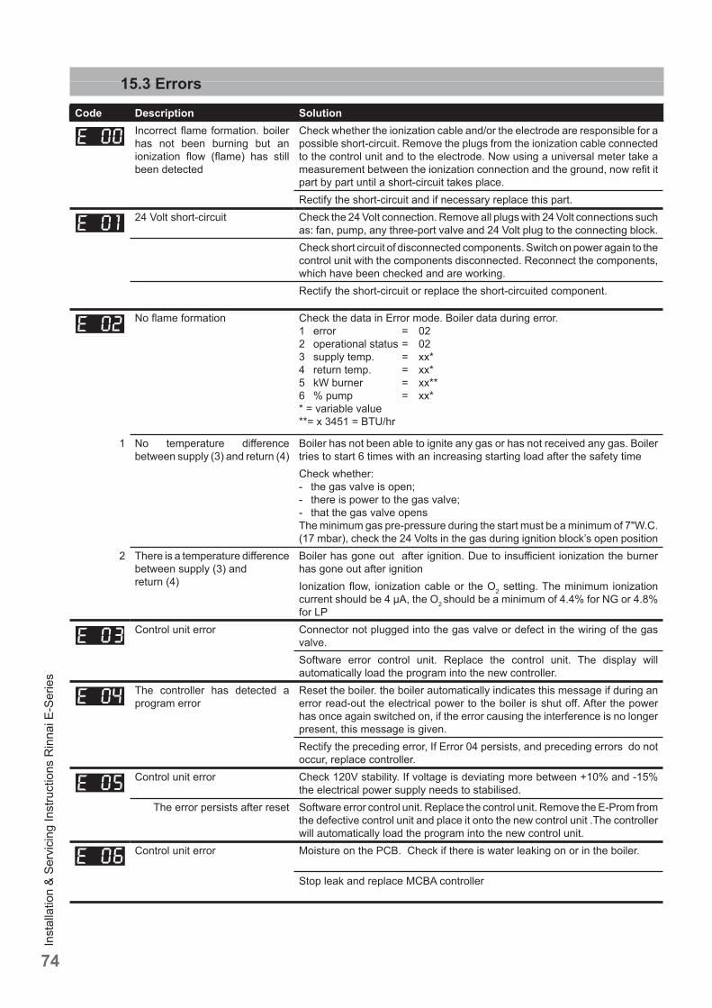
Inst
alla
tion
& Se
rvic
ing
Inst
ruct
ions
Rin
nai E
-Ser
ies
74
15.3 ErrorsCode Description Solution
Incorrect fl ame formation. boiler has not been burning but an ionization fl ow (fl ame) has still been detected
Check whether the ionization cable and/or the electrode are responsible for a possible short-circuit. Remove the plugs from the ionization cable connected to the control unit and to the electrode. Now using a universal meter take a measurement between the ionization connection and the ground, now refi t it part by part until a short-circuit takes place.Rectify the short-circuit and if necessary replace this part.
24 Volt short-circuit Check the 24 Volt connection. Remove all plugs with 24 Volt connections such as: fan, pump, any three-port valve and 24 Volt plug to the connecting block.Check short circuit of disconnected components. Switch on power again to the control unit with the components disconnected. Reconnect the components, which have been checked and are working.Rectify the short-circuit or replace the short-circuited component.
No fl ame formation Check the data in Error mode. Boiler data during error.1 error = 022 operational status = 023 supply temp. = xx*4 return temp. = xx*5 kW burner = xx**6 % pump = xx** = variable value**= x 3451 = BTU/hr
1 No temperature diff erence between supply (3) and return (4)
Boiler has not been able to ignite any gas or has not received any gas. Boiler tries to start 6 times with an increasing starting load after the safety timeCheck whether:- the gas valve is open;- there is power to the gas valve;- that the gas valve opensThe minimum gas pre-pressure during the start must be a minimum of 7"W.C. (17 mbar), check the 24 Volts in the gas during ignition block’s open position
2 There is a temperature diff erence between supply (3) and return (4)
Boiler has gone out after ignition. Due to insuffi cient ionization the burner has gone out after ignitionIonization fl ow, ionization cable or the O2 setting. The minimum ionization current should be 4 μA, the O2 should be a minimum of 4.4% for NG or 4.8% for LP
Control unit error Connector not plugged into the gas valve or defect in the wiring of the gas valve.Software error control unit. Replace the control unit. The display will automatically load the program into the new controller.
The controller has detected a program error
Reset the boiler. the boiler automatically indicates this message if during an error read-out the electrical power to the boiler is shut off . After the power has once again switched on, if the error causing the interference is no longer present, this message is given.Rectify the preceding error, If Error 04 persists, and preceding errors do not occur, replace controller.
Control unit error Check 120V stability. If voltage is deviating more between +10% and -15% the electrical power supply needs to stabilised.
The error persists after reset Software error control unit. Replace the control unit. Remove the E-Prom from the defective control unit and place it onto the new control unit .The controller will automatically load the program into the new control unit.
Control unit error Moisture on the PCB. Check if there is water leaking on or in the boiler.
Stop leak and replace MCBA controller
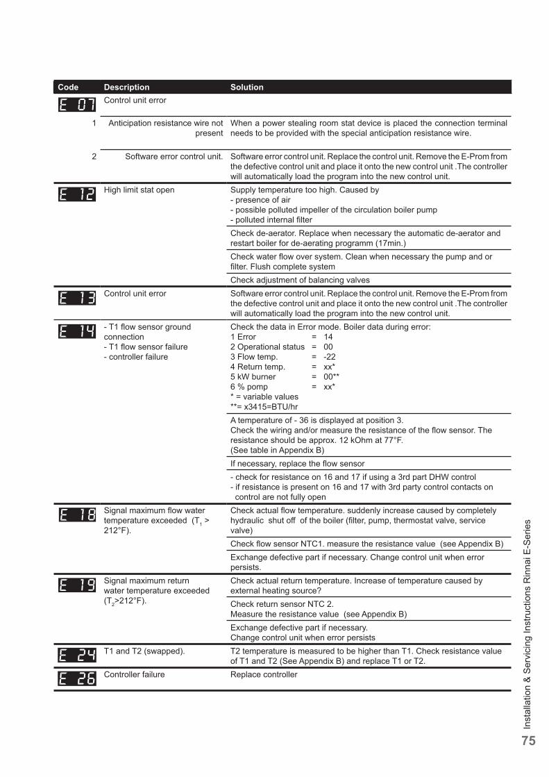
Inst
alla
tion
& Se
rvic
ing
Inst
ruct
ions
Rin
nai E
-Ser
ies
75
Code Description SolutionControl unit error
1 Anticipation resistance wire not present
When a power stealing room stat device is placed the connection terminal needs to be provided with the special anticipation resistance wire.
2 Software error control unit. Software error control unit. Replace the control unit. Remove the E-Prom from the defective control unit and place it onto the new control unit .The controller will automatically load the program into the new control unit.
High limit stat open Supply temperature too high. Caused by - presence of air- possible polluted impeller of the circulation boiler pump- polluted internal fi lterCheck de-aerator. Replace when necessary the automatic de-aerator and restart boiler for de-aerating programm (17min.)Check water fl ow over system. Clean when necessary the pump and or fi lter. Flush complete systemCheck adjustment of balancing valves
Control unit error Software error control unit. Replace the control unit. Remove the E-Prom from the defective control unit and place it onto the new control unit .The controller will automatically load the program into the new control unit.
- T1 fl ow sensor ground connection- T1 fl ow sensor failure- controller failure
Check the data in Error mode. Boiler data during error:1 Error = 142 Operational status = 003 Flow temp. = -224 Return temp. = xx*5 kW burner = 00**6 % pomp = xx** = variable values**= x3415=BTU/hrA temperature of - 36 is displayed at position 3.Check the wiring and/or measure the resistance of the fl ow sensor. The resistance should be approx. 12 kOhm at 77°F.(See table in Appendix B)If necessary, replace the fl ow sensor- check for resistance on 16 and 17 if using a 3rd part DHW control- if resistance is present on 16 and 17 with 3rd party control contacts on control are not fully open
Signal maximum fl ow water temperature exceeded (T1 > 212°F).
Check actual fl ow temperature. suddenly increase caused by completely hydraulic shut off of the boiler (fi lter, pump, thermostat valve, service valve)Check fl ow sensor NTC1. measure the resistance value (see Appendix B) Exchange defective part if necessary. Change control unit when error persists.
Signal maximum return water temperature exceeded (T2>212°F).
Check actual return temperature. Increase of temperature caused by external heating source?Check return sensor NTC 2. Measure the resistance value (see Appendix B)Exchange defective part if necessary. Change control unit when error persists
T1 and T2 (swapped). T2 temperature is measured to be higher than T1. Check resistance value of T1 and T2 (See Appendix B) and replace T1 or T2.
Controller failure Replace controller
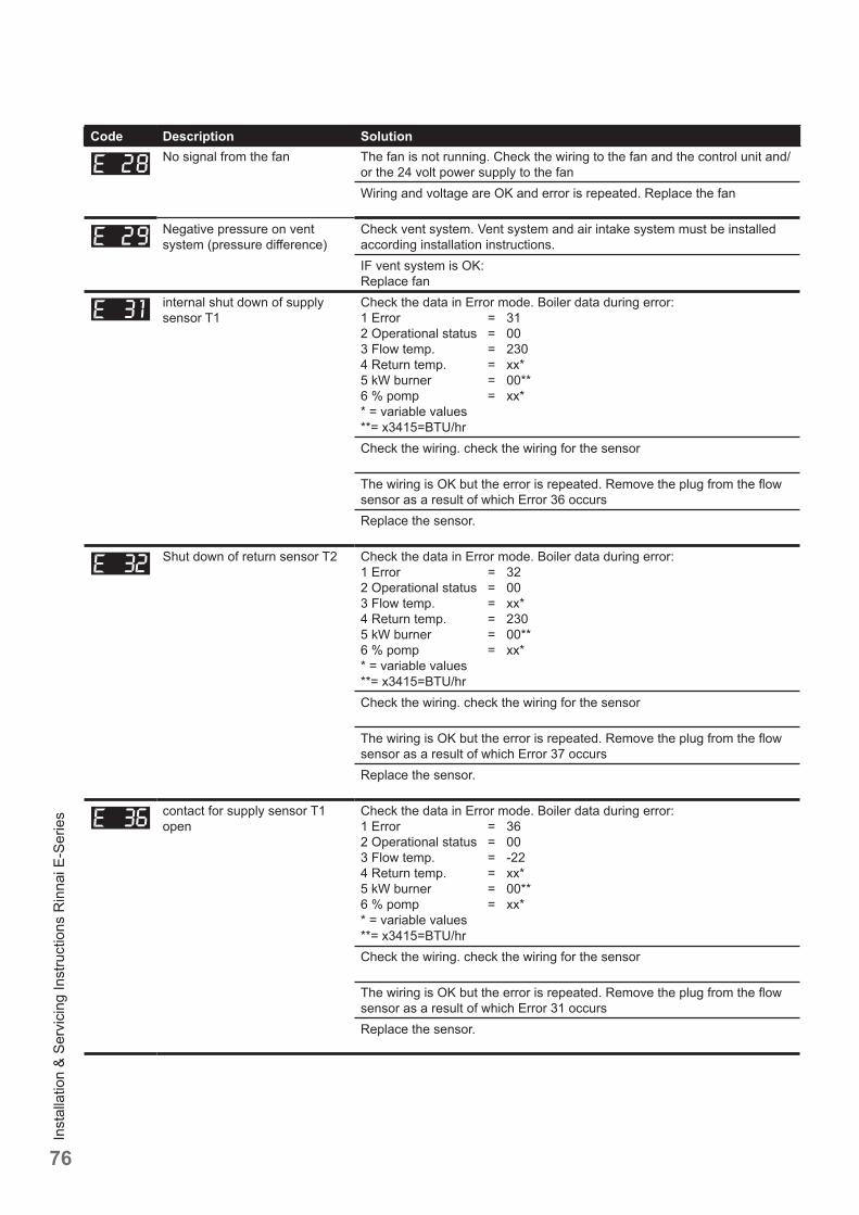
Inst
alla
tion
& Se
rvic
ing
Inst
ruct
ions
Rin
nai E
-Ser
ies
76
Code Description SolutionNo signal from the fan The fan is not running. Check the wiring to the fan and the control unit and/
or the 24 volt power supply to the fanWiring and voltage are OK and error is repeated. Replace the fan
Negative pressure on vent system (pressure diff erence)
Check vent system. Vent system and air intake system must be installed according installation instructions.IF vent system is OK:Replace fan
internal shut down of supply sensor T1
Check the data in Error mode. Boiler data during error:1 Error = 312 Operational status = 003 Flow temp. = 2304 Return temp. = xx*5 kW burner = 00**6 % pomp = xx** = variable values**= x3415=BTU/hrCheck the wiring. check the wiring for the sensor
The wiring is OK but the error is repeated. Remove the plug from the fl ow sensor as a result of which Error 36 occursReplace the sensor.
Shut down of return sensor T2 Check the data in Error mode. Boiler data during error:1 Error = 322 Operational status = 003 Flow temp. = xx*4 Return temp. = 2305 kW burner = 00**6 % pomp = xx** = variable values**= x3415=BTU/hrCheck the wiring. check the wiring for the sensor
The wiring is OK but the error is repeated. Remove the plug from the fl ow sensor as a result of which Error 37 occursReplace the sensor.
contact for supply sensor T1 open
Check the data in Error mode. Boiler data during error:1 Error = 362 Operational status = 003 Flow temp. = -224 Return temp. = xx*5 kW burner = 00**6 % pomp = xx** = variable values**= x3415=BTU/hrCheck the wiring. check the wiring for the sensor
The wiring is OK but the error is repeated. Remove the plug from the fl ow sensor as a result of which Error 31 occursReplace the sensor.
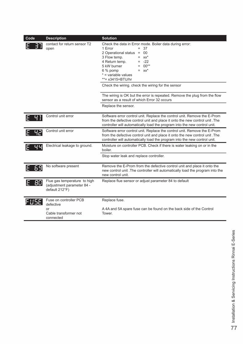
Inst
alla
tion
& Se
rvic
ing
Inst
ruct
ions
Rin
nai E
-Ser
ies
77
Code Description Solutioncontact for return sensor T2 open
Check the data in Error mode. Boiler data during error:1 Error = 372 Operational status = 003 Flow temp. = xx*4 Return temp. = -225 kW burner = 00**6 % pomp = xx** = variable values**= x3415=BTU/hrCheck the wiring. check the wiring for the sensor
The wiring is OK but the error is repeated. Remove the plug from the fl ow sensor as a result of which Error 32 occursReplace the sensor.
Control unit error Software error control unit. Replace the control unit. Remove the E-Prom from the defective control unit and place it onto the new control unit .The controller will automatically load the program into the new control unit.
Control unit error Software error control unit. Replace the control unit. Remove the E-Prom from the defective control unit and place it onto the new control unit .The controller will automatically load the program into the new control unit.
Electrical leakage to ground. Moisture on controller PCB. Check if there is water leaking on or in the boiler.Stop water leak and replace controller.
No software present Remove the E-Prom from the defective control unit and place it onto the new control unit .The controller will automatically load the program into the new control unit.
Flue gas temperature to high (adjustment parameter 84 - default 212°F)
Replace fl ue sensor or adjust parameter 84 to default
Fuse on controller PCB defectiveorCable transformer not connected
Replace fuse.
A 4A and 5A spare fuse can be found on the back side of the Control Tower.
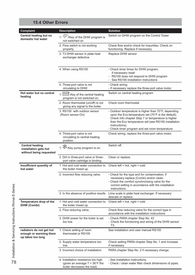
Inst
alla
tion
& Se
rvic
ing
Inst
ruct
ions
Rin
nai E
-Ser
ies
78
Complaint Description SolutionCentral heating but no domestic hot water 1. -Key of the DHW program is
not switched on
Switch on DHW program on the Control Tower
2. Flow switch is not working properly.
Check fl ow and/or check for impurities. Check on functioning. Replace if necessary.
3. T3 DHW sensor in plate heat exchanger defective
Replace DHW sensor
4. When using RS100 - Check timer times for DHW program, if necessary reset- RS100 does not respond to DHW program- See RS100 installation instructions
5. Three-port valve is not circulating to DHW
- Check wiring.- If necessary replace the three-port valve motor.
Hot water but no central heating 1. -Key of the central heating
program is not switched on.
Switch on central heating program
2. Room thermostat (on/off ) is not giving any signal to the boiler.
Check room thermostat
3. RS100 with outdoor sensor (Room sensor-On)
- Outdoor temperature is higher than 70°F, depending upon the Eco-temperature set (70°F is the default). Check Info chapter Step 7 or temperature is higher than the Eco temperature set (see RS100 installation instructions).
- Check timer program and set room temperature.4. Three-port valve is not
circulating to central heating position.
Check wiring, replace the three-port valve motor.
Central heating installation gets hot without being requested
1. -Key pump program is on.Switch off .
2. Dirt in three-port valve or three-port valve cartridge is binding.
Clean or replace.
Insuffi cient quantity of hot water
1. Hot and cold water connection to the boiler mixed up.
Check left = hot, right = cold
2. Incorrect fl ow reducing valve. - Check for the type and for contamination, if necessary replace (Combi) and/or clean.
- Check the comfort synchronising valve for the correct setting in accordance with the installation instructions.
3. In the absence of positive results Lime scale in plate heat exchanger. If necessary descale or replace
Temperature drop of the DHW (Combi)
1. Hot and cold water connection to the boiler mixed up
Check left = hot, right = cold
2. Flow reducing valve. Check fl ow reducing valve for the correct type in accordance with the installation instructions
3. DHW power for the boiler is set too low.
- Check PARA chapter Step No. 43- Check the functioning and wiring of the DHW sensor
T3.radiators do not get hot enough or warming them up takes too long
1. Check setting of room thermostat or RS100
See installation and user manual RS100
2. Supply water temperature too low.
Check setting PARA chapter Step No. 1 and increase if necessary
3. Incorrect choice of installation PARA chapter Step No. 2 if necessary change.
4. Installation resistance too high (given an average T > 36°F the boiler decreases the load).
- See installation instructions.- Check / clean water fi lter check dimensions of pipes.
15.4 Other Errors

Inst
alla
tion
& Se
rvic
ing
Inst
ruct
ions
Rin
nai E
-Ser
ies
79
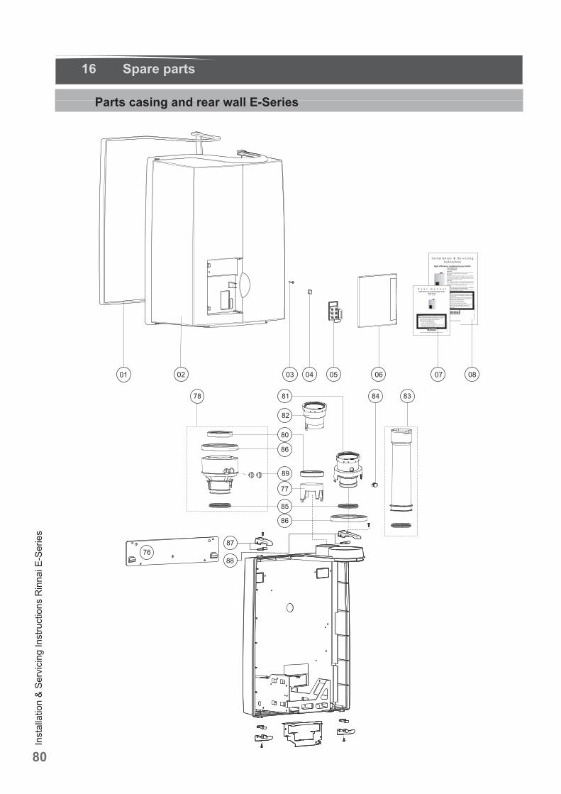
Inst
alla
tion
& Se
rvic
ing
Inst
ruct
ions
Rin
nai E
-Ser
ies
80
16 Spare parts
Parts casing and rear wall E-Series
9 0. 20 /00. 06 .15.U 8
.dev res er segnahC
I n s t a l l a t i o n & S e r v i c i n g Instructions
These instructions to be retained by user.
CAUTION!Read this manual thoroughly before installing, servicing, putting into operation or using this boiler and vent system.WARNING!Improper installation, adjustment, alteration, service or maintenan-ce can cause property damage, personal injury or loss of life. Refer to this manual. For assistance or additional information consult a qualified installer or the gas supplier.CAUTION!The user manual is part of the documentation that is delivered to the installation's operator. Go through the information in this manual with the owner/operator and make sure that he or she is familair with all necessary operating instructions.NOTICE!Installation and service must be performed by a qualified installer, service technician or the gas supplier. In the Commonwealth of Massachusetts this boiler must be instal-led by a licensed Plumber or Gas Fitter.
WARNING!If you do not follow these instructions exactly, a fire or explosion may result causing property damage, personal injury or loss of life.- Do not store or use gasoline or other flammable vapors
and liquids in the vicinity of this or any other appliance.- WHAT TO DO IF YOU SMELL GAS
- Do NOT try to light any appliance.- Do NOT touch any electrical switch. - Do NOT use any phone in your building.- Immediately call your gas supplier from a neighbor’s
phone. Follow the gas supplier’s instructions.- If you cannot reach your gas supllier, call the fire
department.
Pictured: E75CN, E110CN E75CP, E110CP
High efficiency condensing gas boilerE75CN/E110CNE75CP/E110CP
90.30/00 06.25.U8
devrese r segna hC
U s e r m a n u a lHigh efficiency condensing gas boiler
E75CN / E110CNE75CP / E110CP
WARNING!If you do not follow these instructions exactly, a fire or explosion may result causing property damage, personal injury or loss of life.- Do not store or use gasoline or other flammable vapors and
liquids in the vicinity of this or any other appliance.- WHAT TO DO IF YOU SMELL GAS
- Do NOT try to light any appliance.- Do NOT touch any electrical switch. - Do NOT use any phone in your building.- Immediately call your gas supplier from a neighbor’s phone.
Follow the gas supplier’s instructions.- If you cannot reach your gas supllier, call the fire department.
Notice! This manual must be retained for future reference.
81
82
89
78
77
76
84
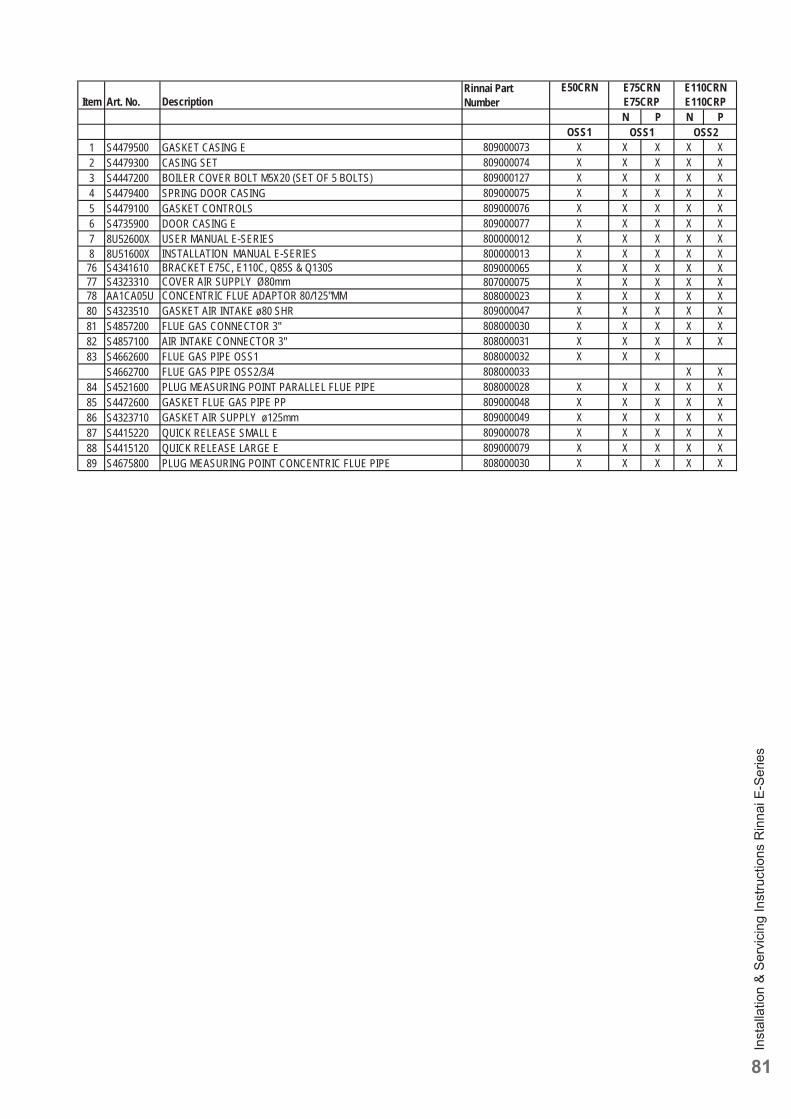
Inst
alla
tion
& Se
rvic
ing
Inst
ruct
ions
Rin
nai E
-Ser
ies
81
Item Art. No. DescriptionRinnai Part Number
E50CRN
N P N POSS1
1 S4479500 GASKET CASING E 809000073 X X X X X2 S4479300 CASING SET 809000074 X X X X X3 S4447200 BOILER COVER BOLT M5X20 (SET OF 5 BOLTS) 809000127 X X X X X4 S4479400 SPRING DOOR CASING 809000075 X X X X X5 S4479100 GASKET CONTROLS 809000076 X X X X X6 S4735900 DOOR CASING E 809000077 X X X X X7 8U52600X USER MANUAL E-SERIES 800000012 X X X X X8 8U51600X INSTALLATION MANUAL E-SERIES 800000013 X X X X X
76 S4341610 BRACKET E75C, E110C, Q85S & Q130S 809000065 X X X X X77 S4323310 COVER AIR SUPPLY Ø80mm 807000075 X X X X X78 AA1CA05U CONCENTRIC FLUE ADAPTOR 80/125"MM 808000023 X X X X X80 S4323510 GASKET AIR INTAKE ø80 SHR 809000047 X X X X X81 S4857200 FLUE GAS CONNECTOR 3" 808000030 X X X X X82 S4857100 AIR INTAKE CONNECTOR 3" 808000031 X X X X X83 S4662600 FLUE GAS PIPE OSS1 808000032 X X X
S4662700 FLUE GAS PIPE OSS2/3/4 808000033 X X84 S4521600 PLUG MEASURING POINT PARALLEL FLUE PIPE 808000028 X X X X X85 S4472600 GASKET FLUE GAS PIPE PP 809000048 X X X X X86 S4323710 GASKET AIR SUPPLY ø125mm 809000049 X X X X X87 S4415220 QUICK RELEASE SMALL E 809000078 X X X X X88 S4415120 QUICK RELEASE LARGE E 809000079 X X X X X89 S4675800 PLUG MEASURING POINT CONCENTRIC FLUE PIPE 808000030 X X X X X
E75CRNE75CRP
E110CRNE110CRP
OSS1 OSS2
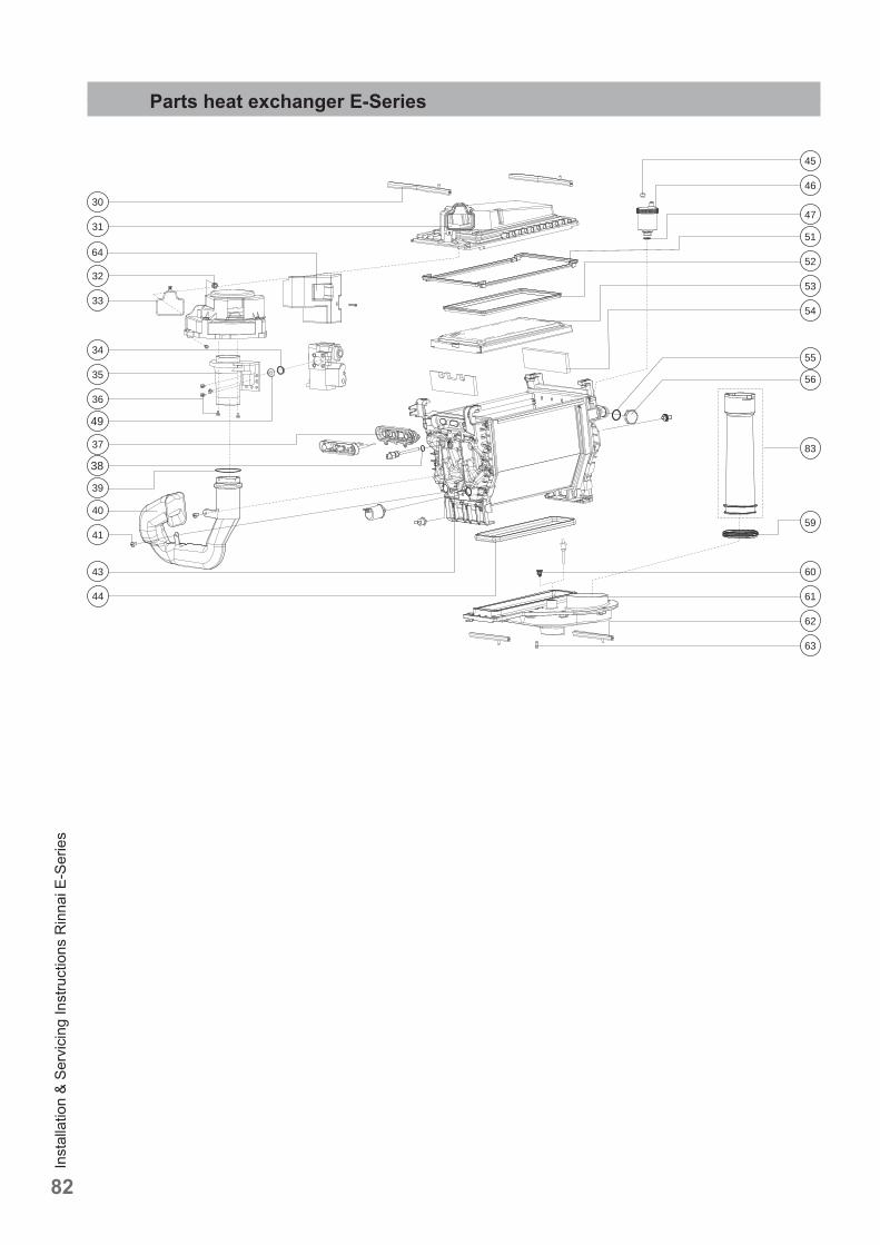
Inst
alla
tion
& Se
rvic
ing
Inst
ruct
ions
Rin
nai E
-Ser
ies
82
Parts heat exchanger E-Series
30
31
64
32
33
34
35
36
40
41
52
54
83
60
61
62
55
53
37
46
51
43
44
39
45
47
59
63
49
38
56
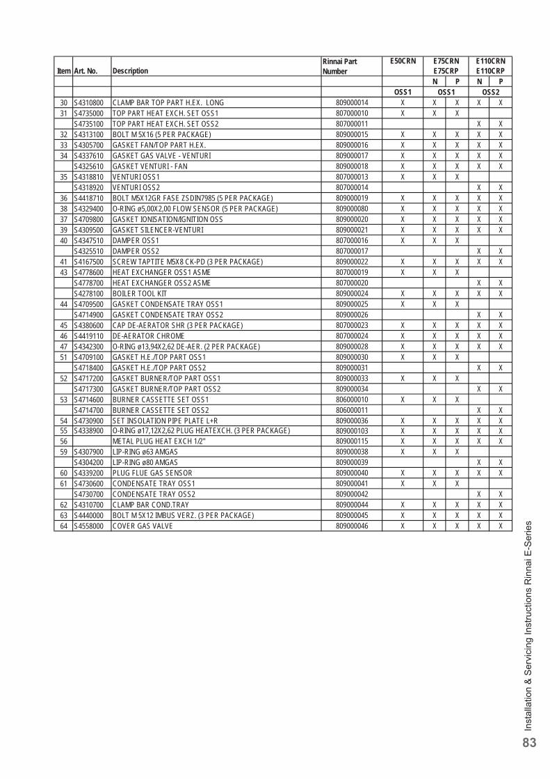
Inst
alla
tion
& Se
rvic
ing
Inst
ruct
ions
Rin
nai E
-Ser
ies
83
Item Art. No. DescriptionRinnai Part Number
E50CRN
N P N POSS1
E75CRNE75CRP
E110CRNE110CRP
OSS1 OSS230 S4310800 CLAMP BAR TOP PART H.EX. LONG 809000014 X X X X X31 S4735000 TOP PART HEAT EXCH. SET OSS1 807000010 X X X
S4735100 TOP PART HEAT EXCH. SET OSS2 807000011 X X32 S4313100 BOLT M 5X16 (5 PER PACKAGE) 809000015 X X X X X33 S4305700 GASKET FAN/TOP PART H.EX. 809000016 X X X X X34 S4337610 GASKET GAS VALVE - VENTURI 809000017 X X X X X
S4325610 GASKET VENTURI - FAN 809000018 X X X X X35 S4318810 VENTURI OSS1 807000013 X X X
S4318920 VENTURI OSS2 807000014 X X36 S4418710 BOLT M5X12GR FASE ZSDIN7985 (5 PER PACKAGE) 809000019 X X X X X38 S4329400 O-RING ø5,00X2,00 FLOW SENSOR (5 PER PACKAGE) 809000080 X X X X X37 S4709800 GASKET IONISATION/IGNITION OSS 809000020 X X X X X39 S4309500 GASKET SILENCER-VENTURI 809000021 X X X X X40 S4347510 DAMPER OSS1 807000016 X X X
S4325510 DAMPER OSS2 807000017 X X41 S4167500 SCREW TAPTITE M5X8 CK-PD (3 PER PACKAGE) 809000022 X X X X X43 S4778600 HEAT EXCHANGER OSS1 ASME 807000019 X X X
S4778700 HEAT EXCHANGER OSS2 ASME 807000020 X XS4278100 BOILER TOOL KIT 809000024 X X X X X
44 S4709500 GASKET CONDENSATE TRAY OSS1 809000025 X X XS4714900 GASKET CONDENSATE TRAY OSS2 809000026 X X
45 S4380600 CAP DE-AERATOR SHR (3 PER PACKAGE) 807000023 X X X X X46 S4419110 DE-AERATOR CHROME 807000024 X X X X X47 S4342300 O-RING ø13,94X2,62 DE-AER. (2 PER PACKAGE) 809000028 X X X X X51 S4709100 GASKET H.E./TOP PART OSS1 809000030 X X X
S4718400 GASKET H.E./TOP PART OSS2 809000031 X X52 S4717200 GASKET BURNER/TOP PART OSS1 809000033 X X X
S4717300 GASKET BURNER/TOP PART OSS2 809000034 X X53 S4714600 BURNER CASSETTE SET OSS1 806000010 X X X
S4714700 BURNER CASSETTE SET OSS2 806000011 X X54 S4730900 SET INSOLATION PIPE PLATE L+R 809000036 X X X X X55 S4338900 O-RING ø17,12X2,62 PLUG HEATEXCH. (3 PER PACKAGE) 809000103 X X X X X56 METAL PLUG HEAT EXCH 1/2" 809000115 X X X X X59 S4307900 LIP-RING ø63 AMGAS 809000038 X X X
S4304200 LIP-RING ø80 AMGAS 809000039 X X60 S4339200 PLUG FLUE GAS SENSOR 809000040 X X X X X61 S4730600 CONDENSATE TRAY OSS1 809000041 X X X
S4730700 CONDENSATE TRAY OSS2 809000042 X X62 S4310700 CLAMP BAR COND.TRAY 809000044 X X X X X63 S4440000 BOLT M 5X12 IMBUS VERZ. (3 PER PACKAGE) 809000045 X X X X X64 S4558000 COVER GAS VALVE 809000046 X X X X X
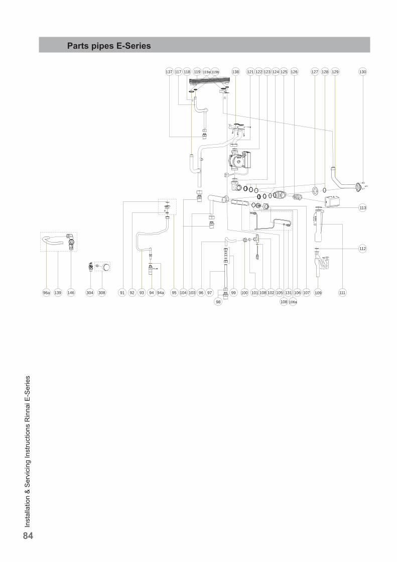
Inst
alla
tion
& Se
rvic
ing
Inst
ruct
ions
Rin
nai E
-Ser
ies
84
9594 105 106 107131
108 106a
109 111
117137 118 119 119a 119b 121138 123 124 125 126 127 128
9392
129 130122
104 103 101100 1029791308304 9996
98
112
113
94a 10814613996a
Parts pipes E-Series
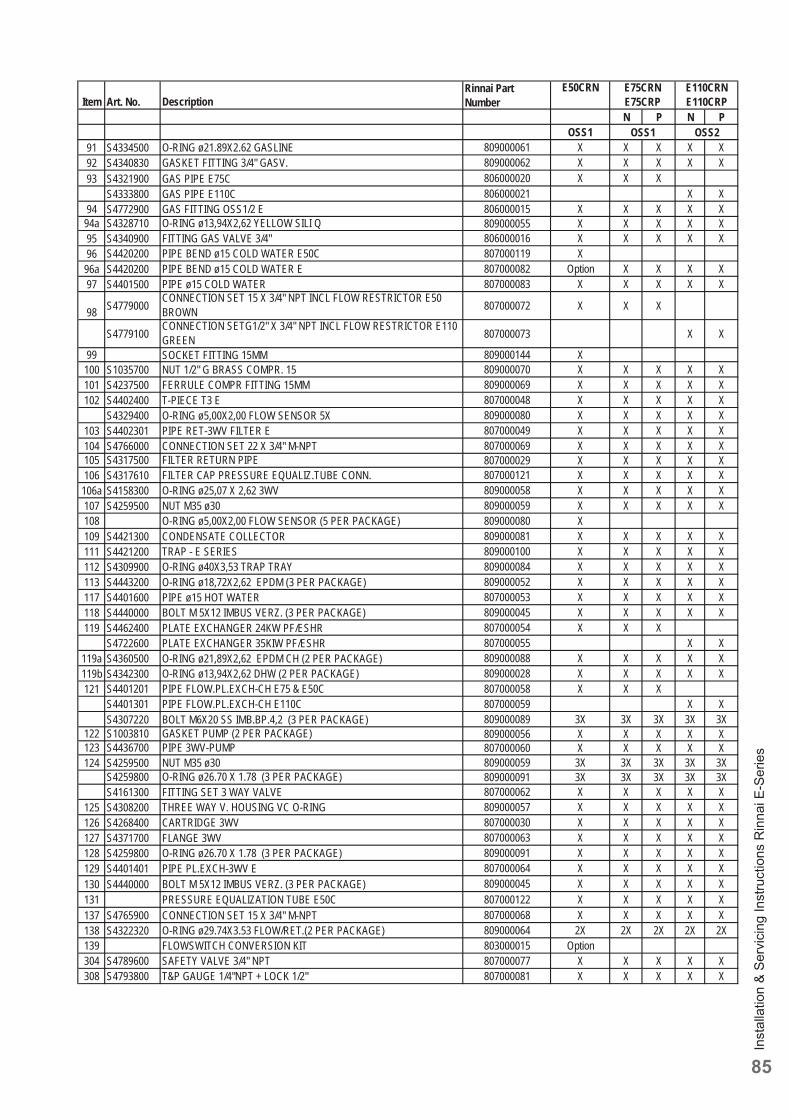
Inst
alla
tion
& Se
rvic
ing
Inst
ruct
ions
Rin
nai E
-Ser
ies
85
Item Art. No. DescriptionRinnai Part Number
E50CRN
N P N POSS1
E75CRNE75CRP
E110CRNE110CRP
OSS1 OSS291 S4334500 O-RING ø21.89X2.62 GASLINE 809000061 X X X X X92 S4340830 GASKET FITTING 3/4" GASV. 809000062 X X X X X93 S4321900 GAS PIPE E75C 806000020 X X X
S4333800 GAS PIPE E110C 806000021 X X94 S4772900 GAS FITTING OSS1/2 E 806000015 X X X X X
94a S4328710 O-RING ø13,94X2,62 YELLOW SILI Q 809000055 X X X X X95 S4340900 FITTING GAS VALVE 3/4" 806000016 X X X X X96 S4420200 PIPE BEND ø15 COLD WATER E50C 807000119 X
96a S4420200 PIPE BEND ø15 COLD WATER E 807000082 Option X X X X97 S4401500 PIPE ø15 COLD WATER 807000083 X X X X X
98 S4779000CONNECTION SET 15 X 3/4" NPT INCL FLOW RESTRICTOR E50 BROWN 807000072 X X X
S4779100CONNECTION SETG1/2" X 3/4" NPT INCL FLOW RESTRICTOR E110 GREEN 807000073 X X
99 SOCKET FITTING 15MM 809000144 X100 S1035700 NUT 1/2" G BRASS COMPR. 15 809000070 X X X X X101 S4237500 FERRULE COMPR FITTING 15MM 809000069 X X X X X102 S4402400 T-PIECE T3 E 807000048 X X X X X
S4329400 O-RING ø5,00X2,00 FLOW SENSOR 5X 809000080 X X X X X103 S4402301 PIPE RET-3WV FILTER E 807000049 X X X X X104 S4766000 CONNECTION SET 22 X 3/4" M-NPT 807000069 X X X X X105 S4317500 FILTER RETURN PIPE 807000029 X X X X X106 S4317610 FILTER CAP PRESSURE EQUALIZ.TUBE CONN. 807000121 X X X X X
106a S4158300 O-RING ø25,07 X 2,62 3WV 809000058 X X X X X107 S4259500 NUT M35 ø30 809000059 X X X X X108 O-RING ø5,00X2,00 FLOW SENSOR (5 PER PACKAGE) 809000080 X109 S4421300 CONDENSATE COLLECTOR 809000081 X X X X X111 S4421200 TRAP - E SERIES 809000100 X X X X X112 S4309900 O-RING ø40X3,53 TRAP TRAY 809000084 X X X X X113 S4443200 O-RING ø18,72X2,62 EPDM (3 PER PACKAGE) 809000052 X X X X X117 S4401600 PIPE ø15 HOT WATER 807000053 X X X X X118 S4440000 BOLT M 5X12 IMBUS VERZ. (3 PER PACKAGE) 809000045 X X X X X119 S4462400 PLATE EXCHANGER 24KW PF/ESHR 807000054 X X X
S4722600 PLATE EXCHANGER 35KIW PF/ESHR 807000055 X X119a S4360500 O-RING ø21,89X2,62 EPDM CH (2 PER PACKAGE) 809000088 X X X X X119b S4342300 O-RING ø13,94X2,62 DHW (2 PER PACKAGE) 809000028 X X X X X121 S4401201 PIPE FLOW.PL.EXCH-CH E75 & E50C 807000058 X X X
S4401301 PIPE FLOW.PL.EXCH-CH E110C 807000059 X XS4307220 BOLT M6X20 SS IMB.BP.4,2 (3 PER PACKAGE) 809000089 3X 3X 3X 3X 3X
122 S1003810 GASKET PUMP (2 PER PACKAGE) 809000056 X X X X X123 S4436700 PIPE 3WV-PUMP 807000060 X X X X X124 S4259500 NUT M35 ø30 809000059 3X 3X 3X 3X 3X
S4259800 O-RING ø26.70 X 1.78 (3 PER PACKAGE) 809000091 3X 3X 3X 3X 3XS4161300 FITTING SET 3 WAY VALVE 807000062 X X X X X
125 S4308200 THREE WAY V. HOUSING VC O-RING 809000057 X X X X X126 S4268400 CARTRIDGE 3WV 807000030 X X X X X127 S4371700 FLANGE 3WV 807000063 X X X X X128 S4259800 O-RING ø26.70 X 1.78 (3 PER PACKAGE) 809000091 X X X X X129 S4401401 PIPE PL.EXCH-3WV E 807000064 X X X X X130 S4440000 BOLT M 5X12 IMBUS VERZ. (3 PER PACKAGE) 809000045 X X X X X131 PRESSURE EQUALIZATION TUBE E50C 807000122 X X X X X137 S4765900 CONNECTION SET 15 X 3/4" M-NPT 807000068 X X X X X138 S4322320 O-RING ø29.74X3.53 FLOW/RET.(2 PER PACKAGE) 809000064 2X 2X 2X 2X 2X139 FLOWSWITCH CONVERSION KIT 803000015 Option304 S4789600 SAFETY VALVE 3/4" NPT 807000077 X X X X X308 S4793800 T&P GAUGE 1/4"NPT + LOCK 1/2" 807000081 X X X X X
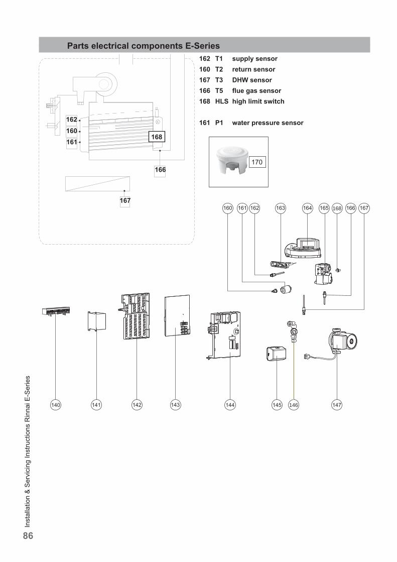
Inst
alla
tion
& Se
rvic
ing
Inst
ruct
ions
Rin
nai E
-Ser
ies
86
Parts electrical components E-Series162 T1 supply sensor160 T2 return sensor167 T3 DHW sensor166 T5 fl ue gas sensor168 HLS high limit switch
161 P1 water pressure sensor
166
167168
146
162160161
168
170
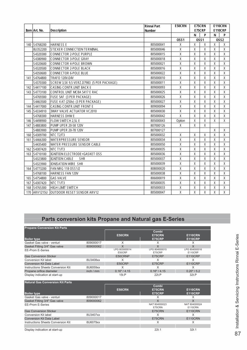
Inst
alla
tion
& Se
rvic
ing
Inst
ruct
ions
Rin
nai E
-Ser
ies
87
Parts conversion kits Propane and Natural gas E-Series
Item Art. No. DescriptionRinnai Part Number
E50CRN
N P N POSS1
E75CRNE75CRP
E110CRNE110CRP
OSS1 OSS2140 S4768200 HARNESS E 805000041 X X X X X
8U352200 STICKER CONNECTION TERMINAL 805000046 X X X X XS4320300 CONNECTOR 2-POLE PURPLE 805000015 X X X X XS4380900 CONNECTOR 3-POLE GRAY 805000018 X X X X XS4320600 CONNECTOR 4-POLE BROWN 805000021 X X X X XS4320500 CONNECTOR 2-POLE BLACK 805000016 X X X X XS4350600 CONNECTOR 6-POLE BLUE 805000022 X X X X X
141 S4764800 TRAFO 120V/24V 805000010 X X X X XS4370300 SCREW 3,5X 9,5 VERZ.D7983 (5 PER PACKAGE) 805000011 X X X X X
142 S4417100 CASING CONTR.UNIT BACK E 809000093 X X X X X143 S4773100 CONTROL UNIT MCBA 5417 E RAC 805000025 X X X X X
S4769300 FUSE 5AF (3 PER PACKAGE) 805000026 X X X X XS4463500 FUSE 4 AT (250v) (3 PER PACKAGE) 805000027 X X X X X
144 S4417000 CASING CONTR.UNIT FRONT E 809000094 X X X X X145 S4334910 3WAY VALVE ACTUATOR VC2010 805000030 X X X X X
S4768300 HARNESS DHW E 805000042 X X X X X146 S4498900 FLOW SWITCH 2,5L E 805000043 Option X X X X147 S4883800 PUMP UPER 20-58 120V 807000126 X X X
S4883900 PUMP UPER 20-78 120V 807000127 X X160 S4309700 NTC T2/T3 805000032 X X X X X161 S4466300 WATERPRESSURE SENSOR 805000034 X X X X X
S4435400 WATER PRESSURE SENSOR CABLE 805000050 X X X X X162 S4307420 NTC T1/T3 805000035 X X X X X163 S4710100 IGNITION ELECTRODE+GASKET OSS 805000036 X X X X X
S4323800 IGNITION CABLE SHR 805000037 X X X X XS4323900 IONISATION WIRE SHR 805000039 X X X X X
164 S4773200 FAN NRG 118 OSS1/2 808000020 X X X X XS4768100 HARNESS FAN 120V 805000038 X X X X X
165 S4754800 GAS VALVE 806000019 X X X X X167 S4307420 NTC T1/T3 805000035 X X X X X168 S4765300 HIGH LIMIT SWITCH 805000033 X X X X X170 ARV1215U OUTDOOR RESET SENSOR ARV12 805000047 X X X X X
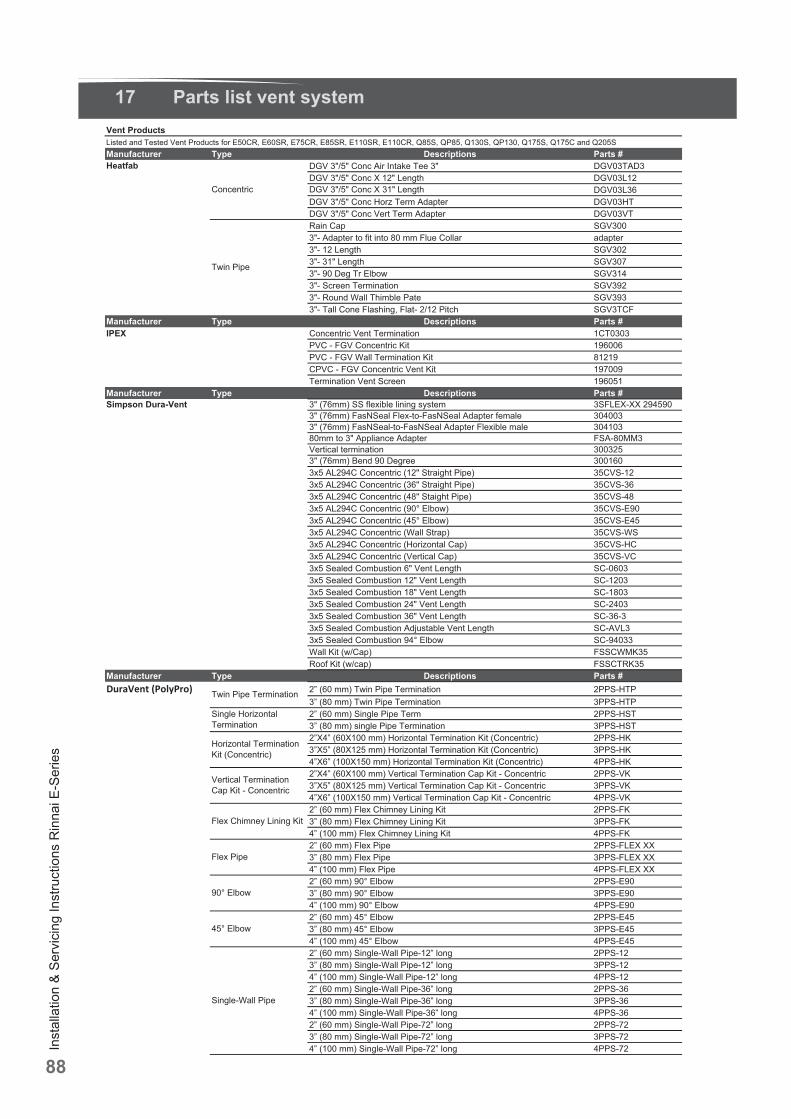
Inst
alla
tion
& Se
rvic
ing
Inst
ruct
ions
Rin
nai E
-Ser
ies
88
17 Parts list vent system
DuraVent (PolyPro)
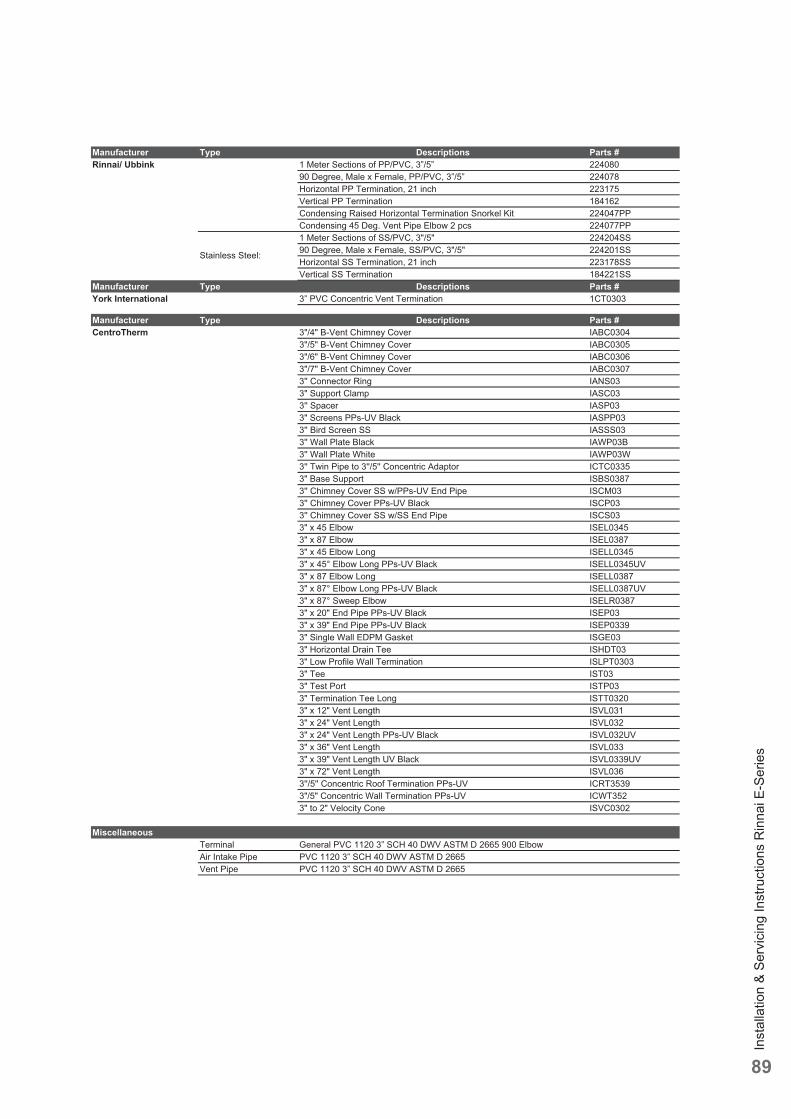
Inst
alla
tion
& Se
rvic
ing
Inst
ruct
ions
Rin
nai E
-Ser
ies
89
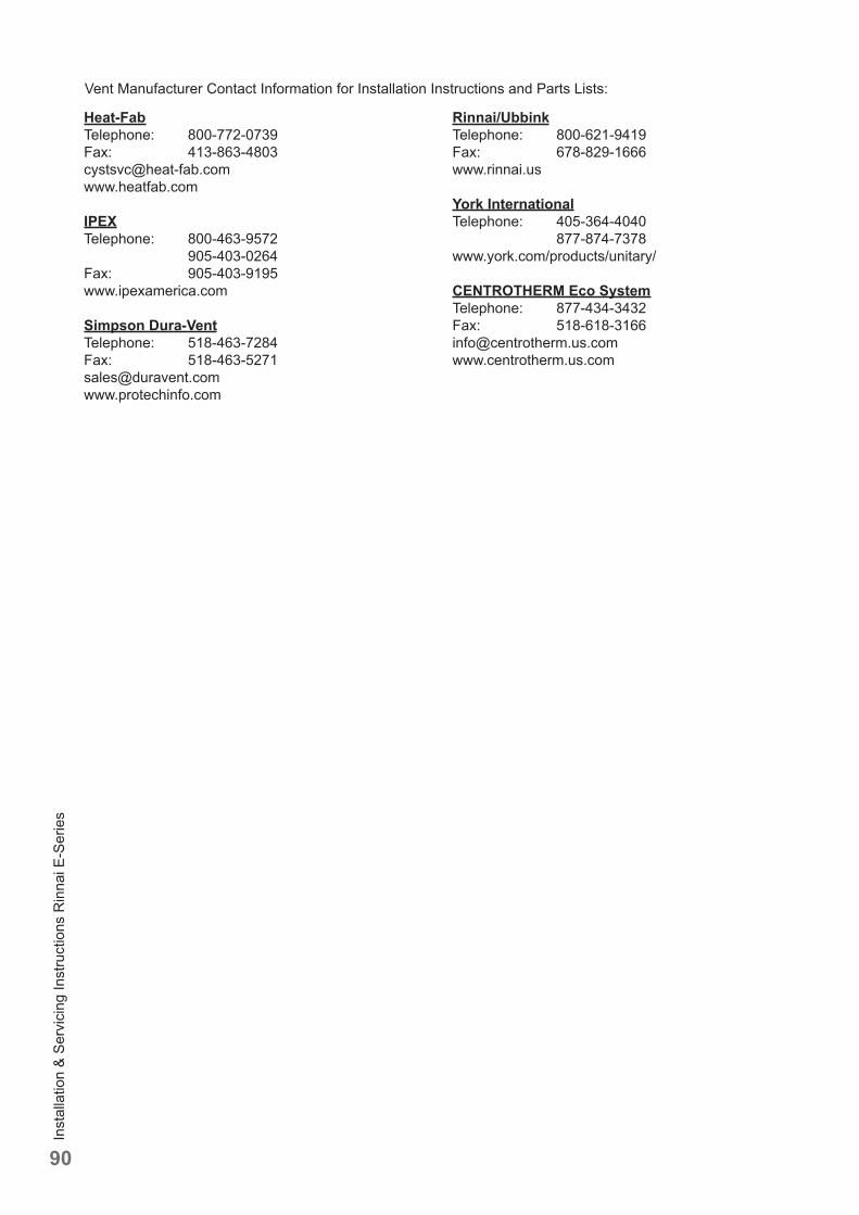
Inst
alla
tion
& Se
rvic
ing
Inst
ruct
ions
Rin
nai E
-Ser
ies
90
Vent Manufacturer Contact Information for Installation Instructions and Parts Lists:
Heat-FabTelephone: 800-772-0739Fax: [email protected]
IPEXTelephone: 800-463-9572 905-403-0264Fax: 905-403-9195www.ipexamerica.com
Simpson Dura-VentTelephone: 518-463-7284Fax: 518-463-5271 [email protected] www.protechinfo.com
Rinnai/UbbinkTelephone: 800-621-9419Fax: 678-829-1666 www.rinnai.us
York InternationalTelephone: 405-364-4040 877-874-7378www.york.com/products/unitary/
CENTROTHERM Eco SystemTelephone: 877-434-3432Fax: [email protected]
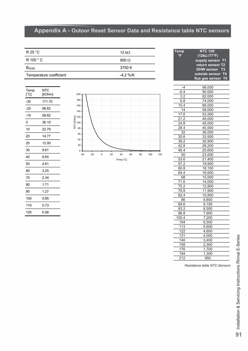
Inst
alla
tion
& Se
rvic
ing
Inst
ruct
ions
Rin
nai E
-Ser
ies
91
R 25 °C 12 k
R 100 ° C 950
B25/85 K 0573
K/% 2,4- tneiciffeoc erutarepmeT
Temp [°C]
NTC [kOhm]
-30 171.70
-20 98.82
-10 58.82
0 36.10
10 22.79
20 14.77
25 12.00
30 9.81
40 6.65
50 4.61
60 3.25
70 2.34
80 1.71
90 1.27
100 0.95
110 0.73
120 0.56
0
20
40
60
80
100
120
140
160
180
200
-40 -20 0 20 40 60 80 100 120
Temp [°C]
NT
C [k
Ohm
]
Appendix A - Outoor Reset Sensor Data and Resistance table NTC sensors
Resistance table NTC-Sensors
Temp NTC 12K °F (12k /77°F)
supply sensor T1 return sensor T2 DHW sensor T3
outside sensor T4 flue gas sensor T5
-4 98,000-0.4 90,0003.2 82,0006.8 74,000
10.4 66,00014 58,000
17.6 53,50021.2 49,00024.8 45,00028.4 40,500
32 36,00035.6 33,50039.2 30,90042.8 28,20046.4 25,600
50 23,00053.6 21,40057.2 19,90060.8 18,10064.4 16,600
68 15,00071.6 14,00075.2 12,90078.8 11,90082.4 10,850
86 9,80089.6 9,10093.2 8,50096.8 7,900
100.4 7,200104 6,500113 5,600122 4,600131 4,000140 3,400158 2,300176 1,700194 1,300212 950
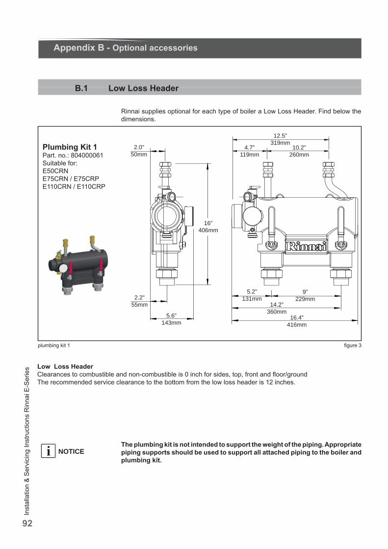
Inst
alla
tion
& Se
rvic
ing
Inst
ruct
ions
Rin
nai E
-Ser
ies
92
B.1 Low Loss Header
Rinnai supplies optional for each type of boiler a Low Loss Header. Find below the dimensions.
2.0”50mm
10.2”260mm
12.5”319mm
4.7”119mm
9”229mm
5.2”131mm
14.2”360mm
16.4”416mm
16”406mm
2.2”55mm
5.6”143mm
Plumbing Kit 1Part. no.: 804000061Suitable for:E50CRNE75CRN / E75CRPE110CRN / E110CRP
plumbing kit 1 fi gure 3
Appendix B - Optional accessories
Low Loss Header Clearances to combustible and non-combustible is 0 inch for sides, top, front and fl oor/groundThe recommended service clearance to the bottom from the low loss header is 12 inches.
The plumbing kit is not intended to support the weight of the piping. Appropriate piping supports should be used to support all attached piping to the boiler and plumbing kit.
NOTICEi
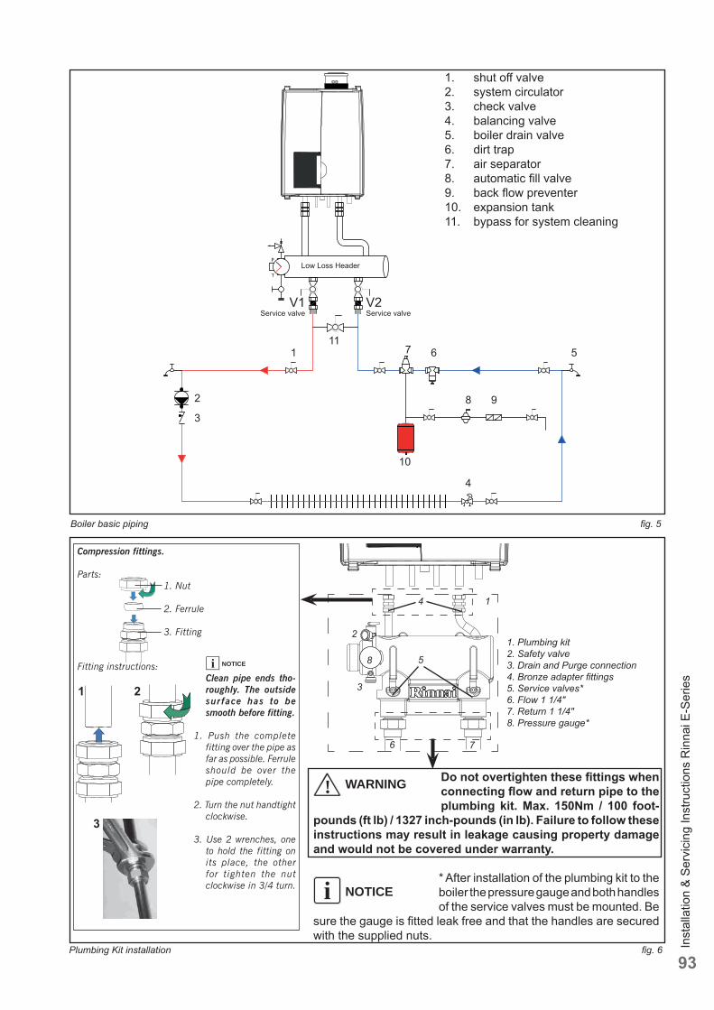
Inst
alla
tion
& Se
rvic
ing
Inst
ruct
ions
Rin
nai E
-Ser
ies
93
Boiler basic piping fi g. 5
1. shut off valve2. system circulator3. check valve4. balancing valve5. boiler drain valve6. dirt trap7. air separator8. automatic fi ll valve9. back fl ow preventer10. expansion tank11. bypass for system cleaning
T
PLow Loss Header
V1Service valve
V2 Service valve
1
2
3
4
567
8 9
11
10
Plumbing Kit installation fi g. 6
1
2
3
4
5
6 7
1. Plumbing kit2. Safety valve3. Drain and Purge connection4. Bronze adapter fi ttings5. Service valves*6. Flow 1 1/4"7. Return 1 1/4"8. Pressure gauge*
8
Compression fittings.
Parts: 1. Nut
2. Ferrule
3. Fitting
Fitting instructions: Clean pipe ends tho-
roughly. The outside sur face has to be smooth before fitting.
1. Push the complete fitting over the pipe as far as possible. Ferrule should be over the pipe completely.
2. Turn the nut handtight clockwise.
3. Use 2 wrenches, one to hold the fitting on its place, the other for tighten the nut clockwise in 3/4 turn.
21
3
! WARNING
NOTICEi
NOTICEi
Do not overtighten these fi ttings when connecting fl ow and return pipe to the plumbing kit. Max. 150Nm / 100 foot-
pounds (ft lb) / 1327 inch-pounds (in lb). Failure to follow these instructions may result in leakage causing property damage and would not be covered under warranty.
* After installation of the plumbing kit to the boiler the pressure gauge and both handles of the service valves must be mounted. Be
sure the gauge is fi tted leak free and that the handles are secured with the supplied nuts.
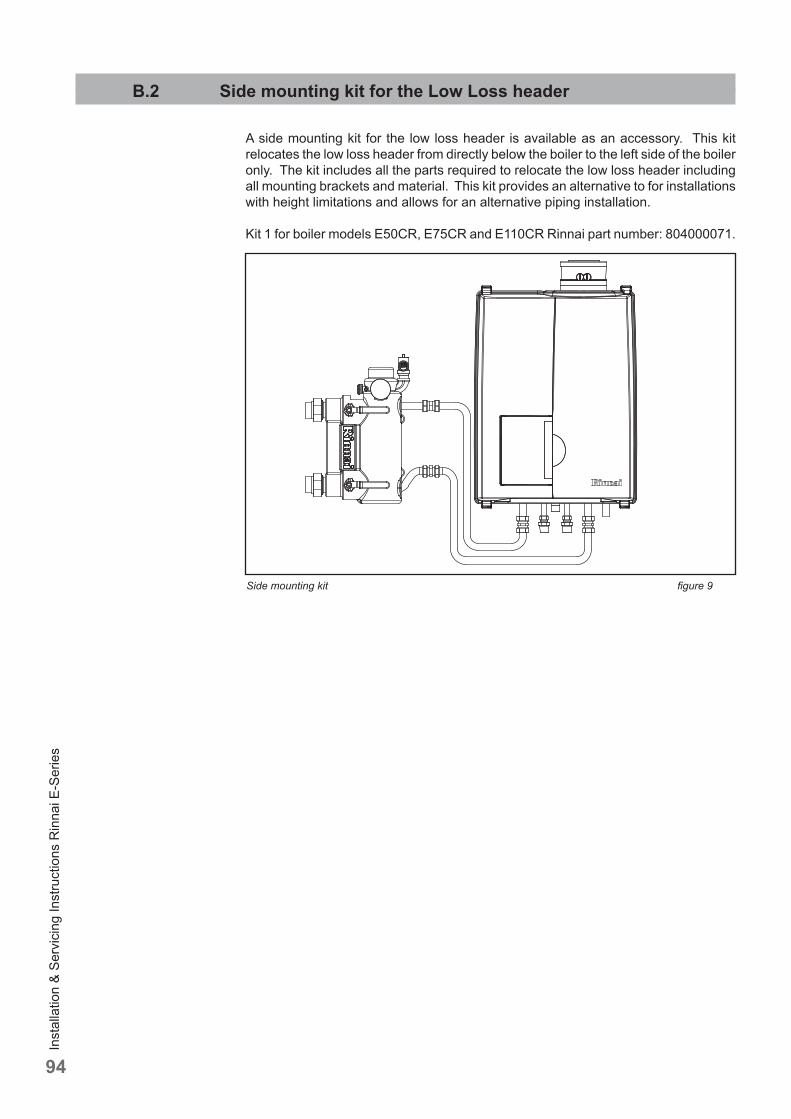
Inst
alla
tion
& Se
rvic
ing
Inst
ruct
ions
Rin
nai E
-Ser
ies
94
B.2 Side mounting kit for the Low Loss header
A side mounting kit for the low loss header is available as an accessory. This kit relocates the low loss header from directly below the boiler to the left side of the boiler only. The kit includes all the parts required to relocate the low loss header including all mounting brackets and material. This kit provides an alternative to for installations with height limitations and allows for an alternative piping installation.
Kit 1 for boiler models E50CR, E75CR and E110CR Rinnai part number: 804000071.
Side mounting kit fi gure 9
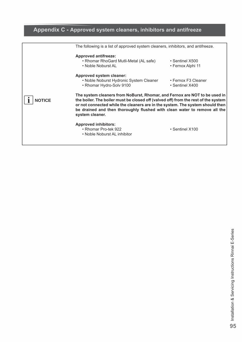
Inst
alla
tion
& Se
rvic
ing
Inst
ruct
ions
Rin
nai E
-Ser
ies
95
The following is a list of approved system cleaners, inhibitors, and antifreeze.
Approved antifreeze: • Rhomar RhoGard Mutli-Metal (AL safe) • Sentinel X500 • Noble Noburst AL • Fernox Alphi 11
Approved system cleaner: • Noble Noburst Hydronic System Cleaner • Fernox F3 Cleaner • Rhomar Hydro-Solv 9100 • Sentinel X400
The system cleaners from NoBurst, Rhomar, and Fernox are NOT to be used in the boiler. The boiler must be closed off (valved off ) from the rest of the system or not connected while the cleaners are in the system. The system should then be drained and then thoroughly fl ushed with clean water to remove all the system cleaner.
Approved inhibitors: • Rhomar Pro-tek 922 • Sentinel X100 • Noble Noburst AL inhibitor
Appendix C - Approved system cleaners, inhibitors and antifreeze
NOTICEi

This
rene
wed
pub
licat
ion
canc
els
all p
revi
ous
inst
alla
tion
inst
ruct
ions
. The
com
pany
rese
rves
the
right
to c
hang
e th
e sp
ecifi
catio
ns a
nd d
imen
sion
s w
ithou
t prio
r not
ice.
Distributor for the USAR i n n a i A m e r i c a C o r p o r a t e • 1 0 3 I n t e r n a t i o n a l D r i v e • P e a c h t r e e C i t y , G A 3 0 2 6 9Toll Free: (800) 621-9419 • Tel: (678) 829-1700 • Fax: (678) 829-1666 • E-mail: [email protected] • Internet: www.rinnai.us
E. & O. E.
800000013 07/2016