Embed Size (px)
Citation preview
EconoMi$er XFactory---Installed OptionLow Leak Economizerfor 2 Speed SAV™ (Staged Air Volume) Systems
Installation, Setup & Troubleshooting Supplement
This document is a supplemental installation instruction for the factory-installed EconoMi$erX (low leak economizer) option. It is to be used with the base unit Installation Instructions for48/50TC, 50TCQ, 48/50HC, and 50HCQ 2-Stage cooling units, sizes 08 – 30, as well as 48/50LCsizes 04– 06. Units equipped with the EconoMi$er X option are identified by an indicator in theunit's model number (see the unit's nameplate). Use Table 1 (on page 2) to identify whetheror not a given unit is equipped with the factory-installed EconoMi$er X.
NOTE: Read the entire instruction manual before starting the installation.
TABLE OF CONTENTS
SAFETY CONSIDERATIONS 2. . . . . . . . . . . . . . . . . . . .
GENERAL 2. . . . . . . . . . . . . . . . . . . . . . . . . . . . . . . . . . . .
Identifying Factory Option 2. . . . . . . . . . . . . . . . . . . . . .
EconoMi$er X 3. . . . . . . . . . . . . . . . . . . . . . . . . . . . . . . .
Unit Installation 3. . . . . . . . . . . . . . . . . . . . . . . . . . . . . .
W7220 Economizer Controller 3. . . . . . . . . . . . . . . . . . .
User Interface 4. . . . . . . . . . . . . . . . . . . . . . . . . . . . . . . .
Menu Structure 4. . . . . . . . . . . . . . . . . . . . . . . . . . . . . . .
CONNECTIONS AND APPLICATIONS 9. . . . . . . . . . . .
W7220 Economizer Module Wiring 9. . . . . . . . . . . . . .
ECONOMIZER CONTROL CONFIGURATIONS 10. . .
Enthalpy Changeover Control 10. . . . . . . . . . . . . . . . . .
Enthalpy Settings 10. . . . . . . . . . . . . . . . . . . . . . . . . . . .
Enthalpy Control Sensor Configuration 11. . . . . . . . . . .
Demand Control Ventilation 12. . . . . . . . . . . . . . . . . . . .
Economizer Occupancy Control 13. . . . . . . . . . . . . . . . .
HARDWARE 14. . . . . . . . . . . . . . . . . . . . . . . . . . . . . . . . .
Actuators 14. . . . . . . . . . . . . . . . . . . . . . . . . . . . . . . . . . .
Supply Air Temperature Sensor 14. . . . . . . . . . . . . . . . .
Outside Air Temperature Sensor 14. . . . . . . . . . . . . . . .
Enthalpy Control Sensor Configuration 14. . . . . . . . . . .
OPERATING SEQUENCES 16. . . . . . . . . . . . . . . . . . . . .
Staged Air Volume (2--Speed) Fan Motor 16. . . . . . . . . . .
W7220 Economizer Control 16. . . . . . . . . . . . . . . . . . . . .
Base Unit Controls 16. . . . . . . . . . . . . . . . . . . . . . . . . . . .
Cooling, Unit with EconoMi$er X without CO2 16. . . . . .
Stage 3 Cooling 18. . . . . . . . . . . . . . . . . . . . . . . . . . . . . .
Heating with EconoMi$er X 18. . . . . . . . . . . . . . . . . . . .
Demand Control Ventilation 18. . . . . . . . . . . . . . . . . . . . .
SETUP AND CONFIGURATION 18. . . . . . . . . . . . . . . .
Initial Menu Display 18. . . . . . . . . . . . . . . . . . . . . . . . . .
Time--out and Screensaver 18. . . . . . . . . . . . . . . . . . . . .
CHECKOUT 19. . . . . . . . . . . . . . . . . . . . . . . . . . . . . . . . .
Status 19. . . . . . . . . . . . . . . . . . . . . . . . . . . . . . . . . . . . . .
Calibration of Sensors 19. . . . . . . . . . . . . . . . . . . . . . . . .
Resetting All Defaults 19. . . . . . . . . . . . . . . . . . . . . . . . .
TROUBLESHOOTING 19. . . . . . . . . . . . . . . . . . . . . . . . .
Power Up Delay 19. . . . . . . . . . . . . . . . . . . . . . . . . . . . .
Power Loss (Outage or Brownout) 19. . . . . . . . . . . . . . .
Alarms 19. . . . . . . . . . . . . . . . . . . . . . . . . . . . . . . . . . . . .
Clearing Alarms 20. . . . . . . . . . . . . . . . . . . . . . . . . . . . .
CONTROL SET POINT ANDCONFIGURATION LOG 22. . . . . . . . . . . . . . . . . . . . . . .
2
SAFETY CONSIDERATIONS
Improper installation, adjustment, alteration, service,maintenance, or use can cause explosion, fire, electricalshock or other conditions which may cause personal injuryor property damage. Consult a qualified installer, serviceagency, or your distributor or branch for information orassistance. The qualified installer or agency must usefactory--authorized kits or accessories when modifying thisproduct. Refer to the individual instructions packaged withthe kits or accessories when installing.
Follow all safety codes. Wear safety glasses and workgloves. Use quenching cloths for brazing operations andhave a fire extinguisher available. Read these instructionsthoroughly and follow all warnings or cautions attached tothe unit. Consult local building codes and appropriatenational electrical codes (in USA, ANSI/NFPA70, NationalElectrical Code (NEC); in Canada, CSA C22.1) for specialrequirements.
It is important to recognize safety information. This is the
safety--alert symbol . When you see this symbol on theunit and in instructions or manuals, be alert to thepotential for personal injury.
Understand the signal words DANGER, WARNING,CAUTION, and NOTE. These words are used with thesafety--alert symbol.
DANGER identifies the most serious hazards which will resultin severe personal injury or death. WARNING signifies hazardswhich could result in personal injury or death.
CAUTION is used to identify unsafe practices, whichmay result in minor personal injury or product andproperty damage.
NOTE is used to highlight suggestions which will result inenhanced installation, reliability, or operation.
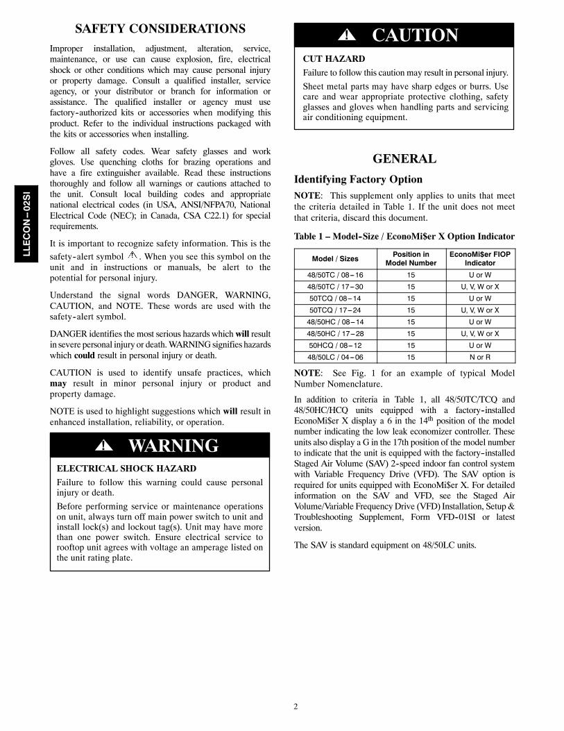
ELECTRICAL SHOCK HAZARD
Failure to follow this warning could cause personalinjury or death.
Before performing service or maintenance operationson unit, always turn off main power switch to unit andinstall lock(s) and lockout tag(s). Unit may have morethan one power switch. Ensure electrical service torooftop unit agrees with voltage an amperage listed onthe unit rating plate.
! WARNING
CUT HAZARD
Failure to follow this caution may result in personal injury.
Sheet metal parts may have sharp edges or burrs. Usecare and wear appropriate protective clothing, safetyglasses and gloves when handling parts and servicingair conditioning equipment.
CAUTION!
GENERAL
Identifying Factory OptionNOTE: This supplement only applies to units that meetthe criteria detailed in Table 1. If the unit does not meetthat criteria, discard this document.
Table 1 – Model--Size / EconoMi$er X Option Indicator
Model / Sizes Position inModel Number
EconoMi$er FIOPIndicator
48/50TC / 08---16 15 U or W
48/50TC / 17---30 15 U, V, W or X
50TCQ / 08---14 15 U or W
50TCQ / 17---24 15 U, V, W or X
48/50HC / 08---14 15 U or W
48/50HC / 17---28 15 U, V, W or X
50HCQ / 08---12 15 U or W
48/50LC / 04---06 15 N or R
NOTE: See Fig. 1 for an example of typical ModelNumber Nomenclature.
In addition to criteria in Table 1, all 48/50TC/TCQ and48/50HC/HCQ units equipped with a factory--installedEconoMi$er X display a 6 in the 14th position of the modelnumber indicating the low leak economizer controller. Theseunits also display a G in the 17th position of the model numberto indicate that the unit is equipped with the factory--installedStaged Air Volume (SAV) 2--speed indoor fan control systemwith Variable Frequency Drive (VFD). The SAV option isrequired for units equipped with EconoMi$er X. For detailedinformation on the SAV and VFD, see the Staged AirVolume/Variable Frequency Drive (VFD) Installation, Setup &Troubleshooting Supplement, Form VFD--01SI or latestversion.
The SAV is standard equipment on 48/50LC units.
LLECON--02SI
3
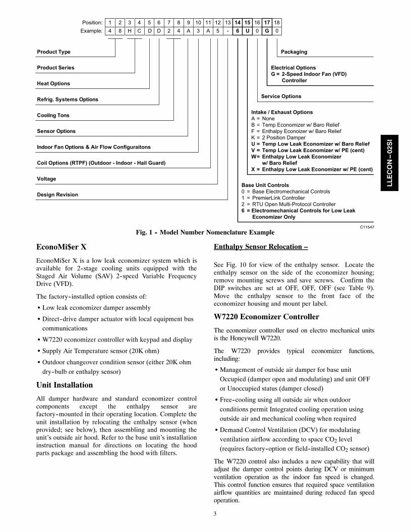
4 8 H C D D 2 4 A 3 A 5 - 6 U 0 G 0
Product Type
Product Series
1Example:Position: 2 3 4 5 6 7 8 9 10 11 12 13 14 15 16 17 18
Sensor Options
Indoor Fan Options & Air Flow Configuraitons
Coil Options (RTPF) (Outdoor - Indoor - Hail Guard)
Electrical OptionsG = 2-Speed Indoor Fan (VFD) ControllerHeat Options
Refrig. Systems Options
Cooling Tons
Packaging
Voltage
Design Revision
Base Unit Controls 0 = Base Electromechanical Controls1 = PremierLink Controller2 = RTU Open Multi-Protocol Controller6 = Electromechanical Controls for Low Leak Economizer Only
Service Options
Intake / Exhaust Options A = NoneB = Temp Economizer w/ Baro ReliefF = Enthalpy Econoizer w/ Baro ReliefK = 2 Position DamperU = Temp Low Leak Economizer w/ Baro ReliefV = Temp Low Leak Economizer w/ PE (cent)W = Enthalpy Low Leak Economizer w/ Baro ReliefX = Enthalpy Low Leak Economizer w/ PE (cent)
C11547Fig. 1 -- Model Number Nomenclature Example
EconoMi$er X
EconoMi$er X is a low leak economizer system which isavailable for 2--stage cooling units equipped with theStaged Air Volume (SAV) 2--speed Variable FrequencyDrive (VFD).
The factory--installed option consists of:
S Low leak economizer damper assembly
S Direct--drive damper actuator with local equipment buscommunications
S W7220 economizer controller with keypad and display
S Supply Air Temperature sensor (20K ohm)
S Outdoor changeover condition sensor (either 20K ohm
dry--bulb or enthalpy sensor)
Unit Installation
All damper hardware and standard economizer controlcomponents except the enthalpy sensor arefactory--mounted in their operating location. Complete theunit installation by relocating the enthalpy sensor (whenprovided; see below), then assembling and mounting theunit’s outside air hood. Refer to the base unit’s installationinstruction manual for directions on locating the hoodparts package and assembling the hood with filters.
Enthalpy Sensor Relocation –
See Fig. 10 for view of the enthalpy sensor. Locate theenthalpy sensor on the side of the economizer housing;remove mounting screws and save screws. Confirm theDIP switches are set at OFF, OFF, OFF (see Table 9).Move the enthalpy sensor to the front face of theeconomizer housing and mount per label.
W7220 Economizer Controller
The economizer controller used on electro mechanical unitsis the Honeywell W7220.
The W7220 provides typical economizer functions,including:
S Management of outside air damper for base unitOccupied (damper open and modulating) and unit OFFor Unoccupied status (damper closed)
S Free--cooling using all outside air when outdoor
conditions permit Integrated cooling operation usingoutside air and mechanical cooling when required
S Demand Control Ventilation (DCV) for modulatingventilation airflow according to space CO2 level(requires factory--option or field--installed CO2 sensor)
The W7220 control also includes a new capability that willadjust the damper control points during DCV or minimumventilation operation as the indoor fan speed is changed.This control function ensures that required space ventilationairflow quantities are maintained during reduced fan speedoperation.
LLECON--02SI
4
Additional control capabilities include automatic detection ofnew sensors and detection of sensor failure or loss ofcommunication.
The W7220 control module includes an integral userinterface with keypad and LCD display that permits directinput of setpoint values and configurations and display ofstatus and alarms.
The W7220 controller is located in the RTU base unit’sControl Box. See the Installation Instructions for this baseunit for the location of the Control Box access panel.
User Interface
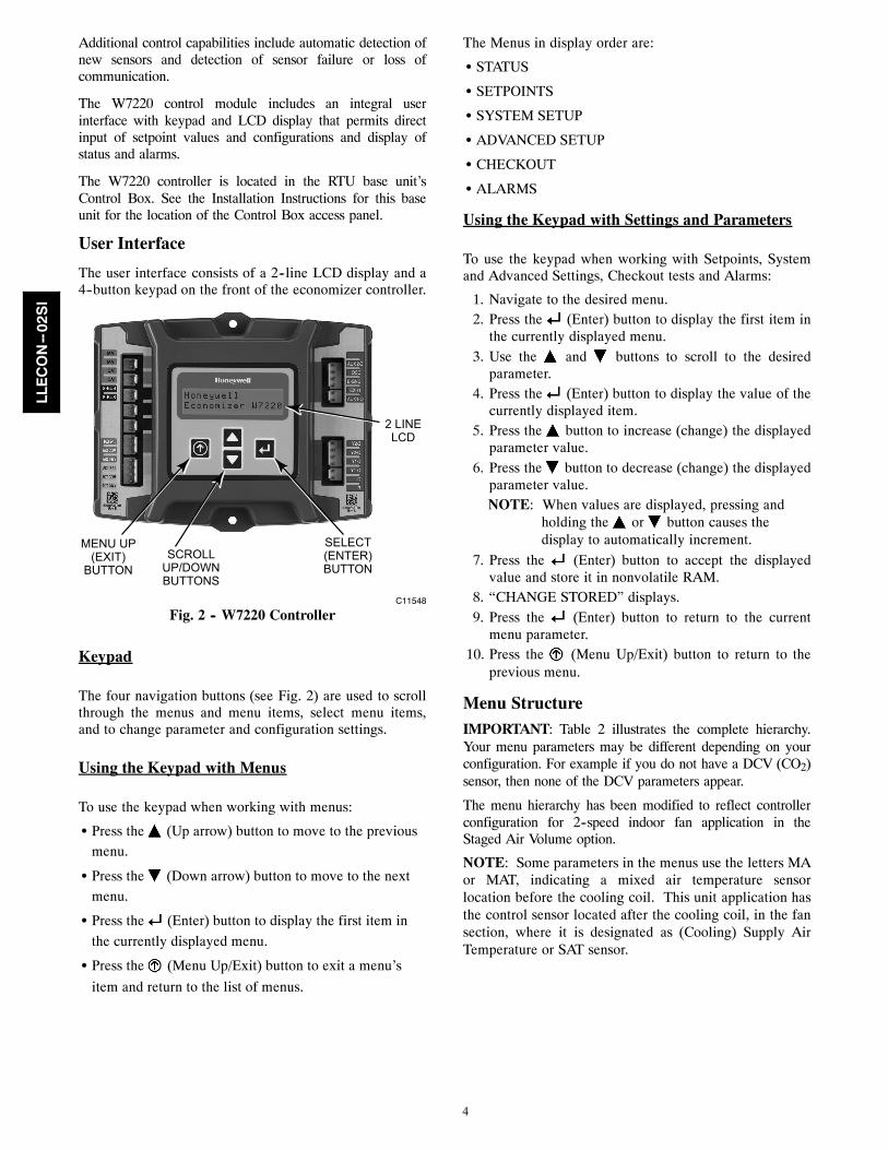
The user interface consists of a 2--line LCD display and a4--button keypad on the front of the economizer controller.
2 LINELCD
MENU UP(EXIT)
BUTTONSCROLL
UP/DOWNBUTTONS
SELECT(ENTER)BUTTON
C11548
Fig. 2 -- W7220 Controller
Keypad
The four navigation buttons (see Fig. 2) are used to scrollthrough the menus and menu items, select menu items,and to change parameter and configuration settings.
Using the Keypad with Menus
To use the keypad when working with menus:
S Press the (Up arrow) button to move to the previousmenu.
S Press the (Down arrow) button to move to the nextmenu.
S Press the (Enter) button to display the first item in
the currently displayed menu.
S Press the (Menu Up/Exit) button to exit a menu’s
item and return to the list of menus.
The Menus in display order are:
S STATUS
S SETPOINTS
S SYSTEM SETUP
S ADVANCED SETUP
S CHECKOUT
S ALARMS
Using the Keypad with Settings and Parameters
To use the keypad when working with Setpoints, Systemand Advanced Settings, Checkout tests and Alarms:
1. Navigate to the desired menu.2. Press the (Enter) button to display the first item in
the currently displayed menu.3. Use the and buttons to scroll to the desired
parameter.4. Press the (Enter) button to display the value of the
currently displayed item.5. Press the button to increase (change) the displayed
parameter value.6. Press the button to decrease (change) the displayed
parameter value.NOTE: When values are displayed, pressing and
holding the or button causes thedisplay to automatically increment.
7. Press the (Enter) button to accept the displayedvalue and store it in nonvolatile RAM.
8. “CHANGE STORED” displays.9. Press the (Enter) button to return to the current
menu parameter.10. Press the (Menu Up/Exit) button to return to the
previous menu.
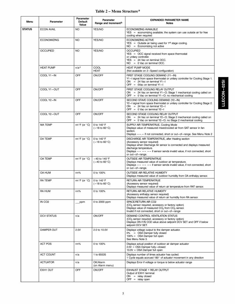
Menu StructureIMPORTANT: Table 2 illustrates the complete hierarchy.Your menu parameters may be different depending on yourconfiguration. For example if you do not have a DCV (CO2)sensor, then none of the DCV parameters appear.
The menu hierarchy has been modified to reflect controllerconfiguration for 2--speed indoor fan application in theStaged Air Volume option.
NOTE: Some parameters in the menus use the letters MAor MAT, indicating a mixed air temperature sensorlocation before the cooling coil. This unit application hasthe control sensor located after the cooling coil, in the fansection, where it is designated as (Cooling) Supply AirTemperature or SAT sensor.
LLECON--02SI
5
Table 2 – Menu Structurea
Menu ParameterParameterDefaultValue
ParameterRange and Incrementb
EXPANDED PARAMETER NAMENotes
STATUS ECON AVAIL NO YES/NO ECONOMIZING AVAIALBLEYES = economizing available; the system can use outside air for freecooling when required
ECONOMIZING NO YES/NO ECONOMIZING ACTIVEYES = Outside air being used for 1st stage cooling.NO = Economizing not active
OCCUPIED NO YES/NO OCCUPIEDYES = OCC signal received from space thermostator unitary controller.YES = 24 Vac on terminal OCC.NO = 0 Vac on terminal OCC.
HEAT PUMP n/a c COOLHEAT
HEAT PUMP MODE(Not available on 2---Speed configuration)
COOL Y1---IN OFF ON/OFF FIRST STAGE COOLING DEMAND (Y1---IN)Y1---I signal from space thermostat or unitary controller for Cooling Stage 1.ON = 24 Vac on terminal Y1---IOFF = 0Vac on terminal Y1---I
COOL Y1---OUT OFF ON/OFF FIRST STAGE COOLING RELAY OUTPUTON = 24 Vac on terminal Y1---O; Stage 1 mechanical cooling called onOFF = 0 Vac on terminal Y1---O; no mechanical cooling
COOL Y2---IN OFF ON/OFF SECOND STAVE COOLING DEMAND (Y2---IN)Y2---I signal from space thermostat or unitary controller for Cooling Stage 2.ON = 24 Vac on terminal Y2---IOFF = 0 Vac on terminal Y2---I
COOL Y2---OUT OFF ON/OFF SECOND STAGE COOLING RELAY OUTPUTON = 24 Vac on terminal Y2---O; Stage 2 mechanical cooling called onOFF = 0 Vac on terminal Y2---O; no Stage 2 mechanical cooling
MA TEMP nn_F (or _C) 0 to 140_F(---18 to 60_C)
SUPPLY AIR TEMPERATRUE, Cooling ModeDisplays value of measured mixed/cooled air from SAT sensor in fansection.Displays --- ---.--- if not connected, short or out---of---range. See Menu Note 2
DA TEMP nn_F (or _C) 0 to 140_F(---18 to 60_C)
DISCHARGE AIR TEMPERATRUE, after Heating section(Accessory sensor required)Displays when Discharge Air sensor is connected and displays measureddischarge temperature.Displays --- --- --- --- --- --- if sensor sends invalid value, if not connected, shortor out---of---range.
OA TEMP nn_F (or _C) ---40 to 140_F(---40 to 60_C)
OUTSIDE AIR TEMPERATRUEDisplays measured value of outdoor air temperature.Displays --- --- --- --- --- --- if sensor sends invalid value, if not connected, shortor out---of---range.
OA HUM nn% 0 to 100% OUTSIDE AIR RELATIVE HUMIDITYDisplays measured value of outdoor humidity from OA enthalpy sensor.
RA TEMP nn_F (or _C) 0 to 140_F(---18 to 60_C)
RETURN AIR TEMPERATRUE(Accessory sensor required)Displays measured value of return air temperature from RAT sensor.
RA HUM nn% 0 to 100% RETURN AIR RELATIVE HUMIDITY(Accessory enthalpy sensor required)Displays measured value of return air humidity from RA sensor.
IN CO2 ___ppm 0 to 2000 ppm SPACE/RETURN AIR CO2(CO2 sensor required, accessory or factory option)Displays value of measured CO2 from CO2 sensor.Invalid if not connected, short or out---of---range
DCV STATUS n/a ON/OFF DEMAND CONTROL VENTILATION STATUS(CO2 sensor required, accessory or factory option)Displays ON if IN CO2 value above setpoint DCV SET and OFF if belowsetpoint DCV SET.
DAMPER OUT 2.0V 2.0 to 10.0V Displays voltage output to the damper actuator.0% = OSA Damper fully closed100%= OSA Damper full openSee Menu Note 3.
ACT POS nn% 0 to 100% Displays actual position of outdoor air damper actuator2.0V = OSA Damper fully---closed10.0V = OSA Damper full open
ACT COUNT n/a 1 to 65535 Displays number of times actuator has cycled.1 Cycle equals accrued 180_ of actuator movement in any direction
ACTUATOR n/a OK/Alarm(on Alarm menu)
Displays Error if voltage or torque is below actuator range
EXH1 OUT OFF ON/OFF EXHAUST STAGE 1 RELAY OUTPUTOutput of EXH1 terminal:ON = relay closedOFF = relay open
LLECON--02SI
6
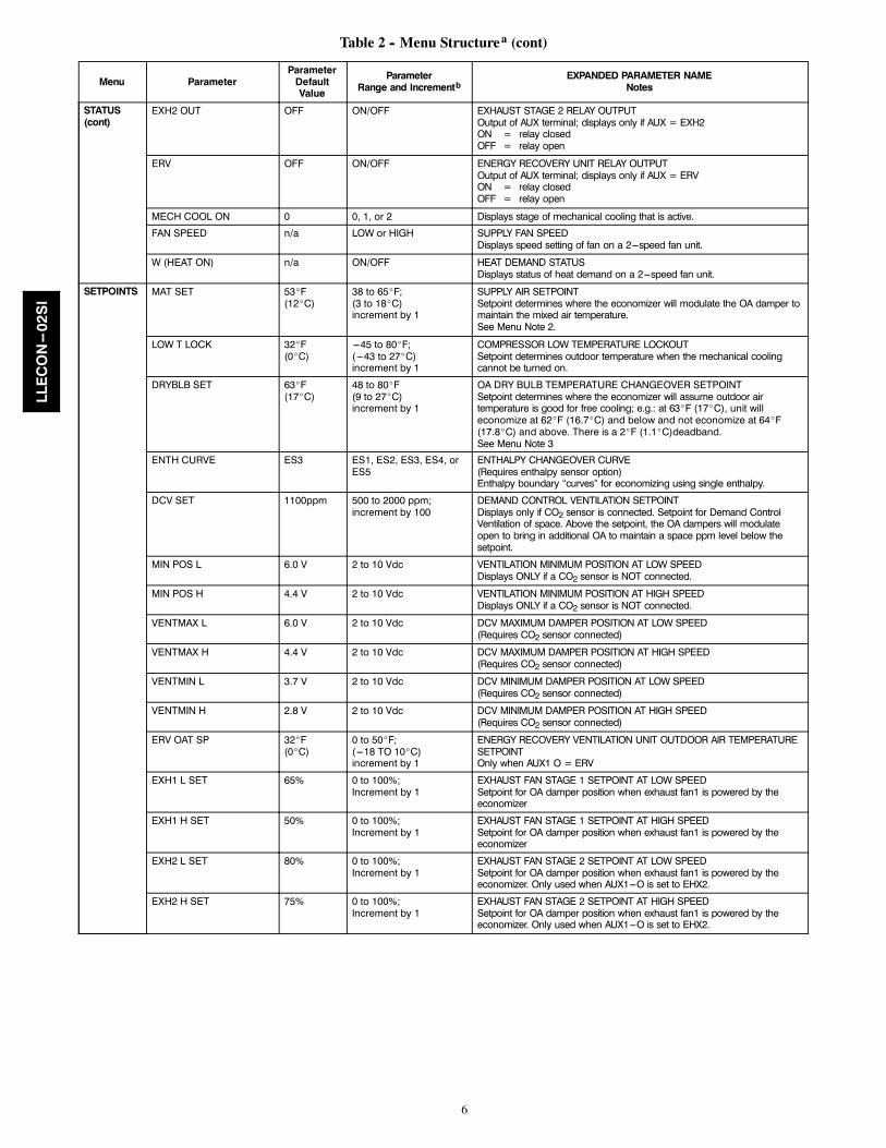
Table 2 -- Menu Structurea (cont)
Menu ParameterParameterDefaultValue
ParameterRange and Incrementb
EXPANDED PARAMETER NAMENotes
STATUS(cont)
EXH2 OUT OFF ON/OFF EXHAUST STAGE 2 RELAY OUTPUTOutput of AUX terminal; displays only if AUX = EXH2ON = relay closedOFF = relay open
ERV OFF ON/OFF ENERGY RECOVERY UNIT RELAY OUTPUTOutput of AUX terminal; displays only if AUX = ERVON = relay closedOFF = relay open
MECH COOL ON 0 0, 1, or 2 Displays stage of mechanical cooling that is active.
FAN SPEED n/a LOW or HIGH SUPPLY FAN SPEEDDisplays speed setting of fan on a 2---speed fan unit.
W (HEAT ON) n/a ON/OFF HEAT DEMAND STATUSDisplays status of heat demand on a 2---speed fan unit.
SETPOINTS MAT SET 53_F(12_C)
38 to 65_F;(3 to 18_C)increment by 1
SUPPLY AIR SETPOINTSetpoint determines where the economizer will modulate the OA damper tomaintain the mixed air temperature.See Menu Note 2.
LOW T LOCK 32_F(0_C)
---45 to 80_F;( ---43 to 27_C)increment by 1
COMPRESSOR LOW TEMPERATURE LOCKOUTSetpoint determines outdoor temperature when the mechanical coolingcannot be turned on.
DRYBLB SET 63_F(17_C)
48 to 80_F(9 to 27_C)increment by 1
OA DRY BULB TEMPERATURE CHANGEOVER SETPOINTSetpoint determines where the economizer will assume outdoor airtemperature is good for free cooling; e.g.: at 63_F (17_C), unit willeconomize at 62_F (16.7_C) and below and not economize at 64_F(17.8_C) and above. There is a 2_F (1.1_C)deadband.See Menu Note 3
ENTH CURVE ES3 ES1, ES2, ES3, ES4, orES5
ENTHALPY CHANGEOVER CURVE(Requires enthalpy sensor option)Enthalpy boundary “curves” for economizing using single enthalpy.
DCV SET 1100ppm 500 to 2000 ppm;increment by 100
DEMAND CONTROL VENTILATION SETPOINTDisplays only if CO2 sensor is connected. Setpoint for Demand ControlVentilation of space. Above the setpoint, the OA dampers will modulateopen to bring in additional OA to maintain a space ppm level below thesetpoint.
MIN POS L 6.0 V 2 to 10 Vdc VENTILATION MINIMUM POSITION AT LOW SPEEDDisplays ONLY if a CO2 sensor is NOT connected.
MIN POS H 4.4 V 2 to 10 Vdc VENTILATION MINIMUM POSITION AT HIGH SPEEDDisplays ONLY if a CO2 sensor is NOT connected.
VENTMAX L 6.0 V 2 to 10 Vdc DCV MAXIMUM DAMPER POSITION AT LOW SPEED(Requires CO2 sensor connected)
VENTMAX H 4.4 V 2 to 10 Vdc DCV MAXIMUM DAMPER POSITION AT HIGH SPEED(Requires CO2 sensor connected)
VENTMIN L 3.7 V 2 to 10 Vdc DCV MINIMUM DAMPER POSITION AT LOW SPEED(Requires CO2 sensor connected)
VENTMIN H 2.8 V 2 to 10 Vdc DCV MINIMUM DAMPER POSITION AT HIGH SPEED(Requires CO2 sensor connected)
ERV OAT SP 32_F(0_C)
0 to 50_F;( ---18 TO 10_C)increment by 1
ENERGY RECOVERY VENTILATION UNIT OUTDOOR AIR TEMPERATURESETPOINTOnly when AUX1 O = ERV
EXH1 L SET 65% 0 to 100%;Increment by 1
EXHAUST FAN STAGE 1 SETPOINT AT LOW SPEEDSetpoint for OA damper position when exhaust fan1 is powered by theeconomizer
EXH1 H SET 50% 0 to 100%;Increment by 1
EXHAUST FAN STAGE 1 SETPOINT AT HIGH SPEEDSetpoint for OA damper position when exhaust fan1 is powered by theeconomizer
EXH2 L SET 80% 0 to 100%;Increment by 1
EXHAUST FAN STAGE 2 SETPOINT AT LOW SPEEDSetpoint for OA damper position when exhaust fan1 is powered by theeconomizer. Only used when AUX1---O is set to EHX2.
EXH2 H SET 75% 0 to 100%;Increment by 1
EXHAUST FAN STAGE 2 SETPOINT AT HIGH SPEEDSetpoint for OA damper position when exhaust fan1 is powered by theeconomizer. Only used when AUX1---O is set to EHX2.
LLECON--02SI
7
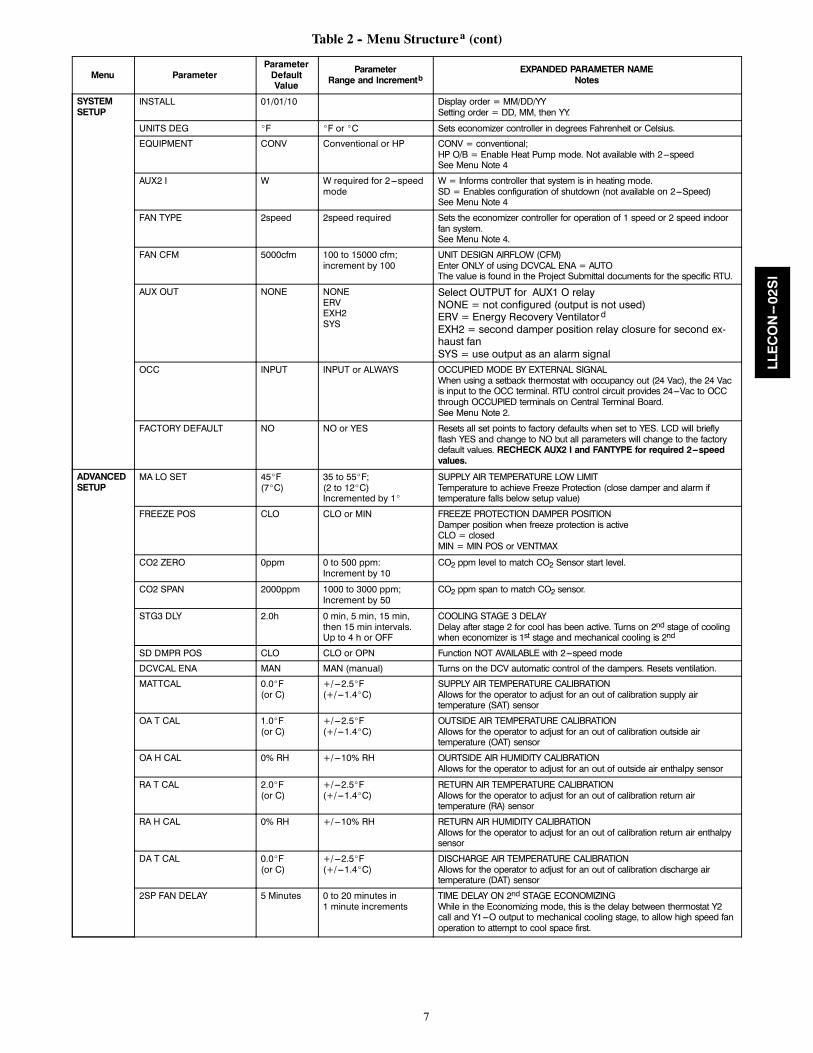
Table 2 -- Menu Structurea (cont)
Menu ParameterParameterDefaultValue
ParameterRange and Incrementb
EXPANDED PARAMETER NAMENotes
SYSTEMSETUP
INSTALL 01/01/10 Display order = MM/DD/YYSetting order = DD, MM, then YY.
UNITS DEG _F _F or _C Sets economizer controller in degrees Fahrenheit or Celsius.
EQUIPMENT CONV Conventional or HP CONV = conventional;HP O/B = Enable Heat Pump mode. Not available with 2---speedSee Menu Note 4
AUX2 I W W required for 2---speedmode
W = Informs controller that system is in heating mode.SD = Enables configuration of shutdown (not available on 2---Speed)See Menu Note 4
FAN TYPE 2speed 2speed required Sets the economizer controller for operation of 1 speed or 2 speed indoorfan system.See Menu Note 4.
FAN CFM 5000cfm 100 to 15000 cfm;increment by 100
UNIT DESIGN AIRFLOW (CFM)Enter ONLY of using DCVCAL ENA = AUTOThe value is found in the Project Submittal documents for the specific RTU.
AUX OUT NONE NONEERVEXH2SYS
Select OUTPUT for AUX1 O relayNONE = not configured (output is not used)ERV = Energy Recovery VentilatordEXH2 = second damper position relay closure for second ex-haust fanSYS = use output as an alarm signal
OCC INPUT INPUT or ALWAYS OCCUPIED MODE BY EXTERNAL SIGNALWhen using a setback thermostat with occupancy out (24 Vac), the 24 Vacis input to the OCC terminal. RTU control circuit provides 24---Vac to OCCthrough OCCUPIED terminals on Central Terminal Board.See Menu Note 2.
FACTORY DEFAULT NO NO or YES Resets all set points to factory defaults when set to YES. LCD will brieflyflash YES and change to NO but all parameters will change to the factorydefault values. RECHECK AUX2 I and FANTYPE for required 2---speedvalues.
ADVANCEDSETUP
MA LO SET 45_F(7_C)
35 to 55_F;(2 to 12_C)Incremented by 1_
SUPPLY AIR TEMPERATURE LOW LIMITTemperature to achieve Freeze Protection (close damper and alarm iftemperature falls below setup value)
FREEZE POS CLO CLO or MIN FREEZE PROTECTION DAMPER POSITIONDamper position when freeze protection is activeCLO = closedMIN = MIN POS or VENTMAX
CO2 ZERO 0ppm 0 to 500 ppm:Increment by 10
CO2 ppm level to match CO2 Sensor start level.
CO2 SPAN 2000ppm 1000 to 3000 ppm;Increment by 50
CO2 ppm span to match CO2 sensor.
STG3 DLY 2.0h 0 min, 5 min, 15 min,then 15 min intervals.Up to 4 h or OFF
COOLING STAGE 3 DELAYDelay after stage 2 for cool has been active. Turns on 2nd stage of coolingwhen economizer is 1st stage and mechanical cooling is 2nd
SD DMPR POS CLO CLO or OPN Function NOT AVAILABLE with 2---speed mode
DCVCAL ENA MAN MAN (manual) Turns on the DCV automatic control of the dampers. Resets ventilation.
MATTCAL 0.0_F(or C)
+/---2.5_F(+/---1.4_C)
SUPPLY AIR TEMPERATURE CALIBRATIONAllows for the operator to adjust for an out of calibration supply airtemperature (SAT) sensor
OA T CAL 1.0_F(or C)
+/---2.5_F(+/---1.4_C)
OUTSIDE AIR TEMPERATURE CALIBRATIONAllows for the operator to adjust for an out of calibration outside airtemperature (OAT) sensor
OA H CAL 0% RH +/---10% RH OURTSIDE AIR HUMIDITY CALIBRATIONAllows for the operator to adjust for an out of outside air enthalpy sensor
RA T CAL 2.0_F(or C)
+/---2.5_F(+/---1.4_C)
RETURN AIR TEMPERATURE CALIBRATIONAllows for the operator to adjust for an out of calibration return airtemperature (RA) sensor
RA H CAL 0% RH +/---10% RH RETURN AIR HUMIDITY CALIBRATIONAllows for the operator to adjust for an out of calibration return air enthalpysensor
DA T CAL 0.0_F(or C)
+/---2.5_F(+/---1.4_C)
DISCHARGE AIR TEMPERATURE CALIBRATIONAllows for the operator to adjust for an out of calibration discharge airtemperature (DAT) sensor
2SP FAN DELAY 5 Minutes 0 to 20 minutes in1 minute increments
TIME DELAY ON 2nd STAGE ECONOMIZINGWhile in the Economizing mode, this is the delay between thermostat Y2call and Y1---O output to mechanical cooling stage, to allow high speed fanoperation to attempt to cool space first.
LLECON--02SI
8
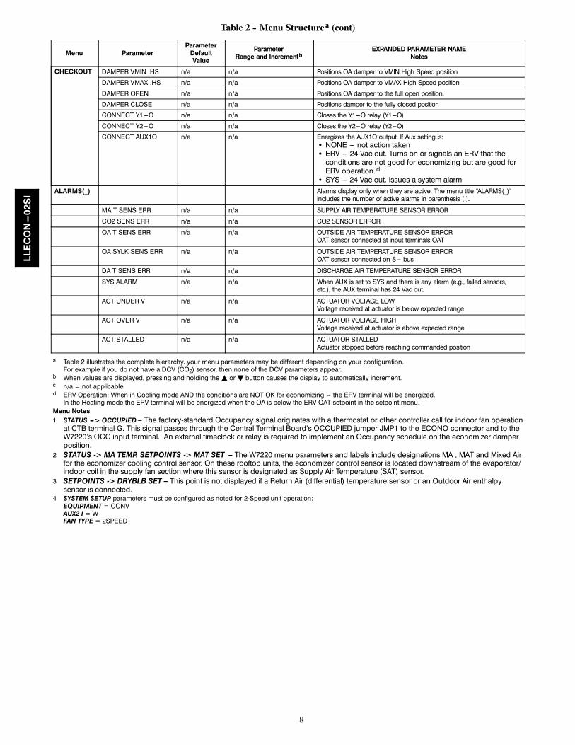
Table 2 -- Menu Structurea (cont)
Menu ParameterParameterDefaultValue
ParameterRange and Incrementb
EXPANDED PARAMETER NAMENotes
CHECKOUT DAMPER VMIN .HS n/a n/a Positions OA damper to VMIN High Speed position
DAMPER VMAX .HS n/a n/a Positions OA damper to VMAX High Speed position
DAMPER OPEN n/a n/a Positions OA damper to the full open position.
DAMPER CLOSE n/a n/a Positions damper to the fully closed position
CONNECT Y1---O n/a n/a Closes the Y1---O relay (Y1---O)
CONNECT Y2---O n/a n/a Closes the Y2---O relay (Y2---O)
CONNECT AUX1O n/a n/a Energizes the AUX1O output. If Aux setting is:S NONE --- not action takenS ERV --- 24 Vac out. Turns on or signals an ERV that theconditions are not good for economizing but are good forERV operation.d
S SYS --- 24 Vac out. Issues a system alarmALARMS(_) Alarms display only when they are active. The menu title “ALARMS(_)”
includes the number of active alarms in parenthesis ( ).
MA T SENS ERR n/a n/a SUPPLY AIR TEMPERATURE SENSOR ERROR
CO2 SENS ERR n/a n/a CO2 SENSOR ERROR
OA T SENS ERR n/a n/a OUTSIDE AIR TEMPERATURE SENSOR ERROROAT sensor connected at input terminals OAT
OA SYLK SENS ERR n/a n/a OUTSIDE AIR TEMPERATURE SENSOR ERROROAT sensor connected on S--- bus
DA T SENS ERR n/a n/a DISCHARGE AIR TEMPERATURE SENSOR ERROR
SYS ALARM n/a n/a When AUX is set to SYS and there is any alarm (e.g., failed sensors,etc.), the AUX terminal has 24 Vac out.
ACT UNDER V n/a n/a ACTUATOR VOLTAGE LOWVoltage received at actuator is below expected range
ACT OVER V n/a n/a ACTUATOR VOLTAGE HIGHVoltage received at actuator is above expected range
ACT STALLED n/a n/a ACTUATOR STALLEDActuator stopped before reaching commanded position
a Table 2 illustrates the complete hierarchy. your menu parameters may be different depending on your configuration.For example if you do not have a DCV (CO2) sensor, then none of the DCV parameters appear.
b When values are displayed, pressing and holding theY orB button causes the display to automatically increment.c n/a = not applicabled ERV Operation: When in Cooling mode AND the conditions are NOT OK for economizing --- the ERV terminal will be energized.In the Heating mode the ERV terminal will be energized when the OA is below the ERV OAT setpoint in the setpoint menu.
Menu Notes1 STATUS ---> OCCUPIED – The factory-standard Occupancy signal originates with a thermostat or other controller call for indoor fan operationat CTB terminal G. This signal passes through the Central Terminal Board’s OCCUPIED jumper JMP1 to the ECONO connector and to theW7220’s OCC input terminal. An external timeclock or relay is required to implement an Occupancy schedule on the economizer damperposition.
2 STATUS -> MA TEMP, SETPOINTS -> MAT SET – The W7220 menu parameters and labels include designations MA , MAT and Mixed Airfor the economizer cooling control sensor. On these rooftop units, the economizer control sensor is located downstream of the evaporator/indoor coil in the supply fan section where this sensor is designated as Supply Air Temperature (SAT) sensor.
3 SETPOINTS -> DRYBLB SET – This point is not displayed if a Return Air (differential) temperature sensor or an Outdoor Air enthalpysensor is connected.
4 SYSTEM SETUP parameters must be configured as noted for 2-Speed unit operation:EQUIPMENT = CONVAUX2 I = WFAN TYPE = 2SPEED
LLECON--02SI
9
CONNECTIONS AND APPLICATIONS
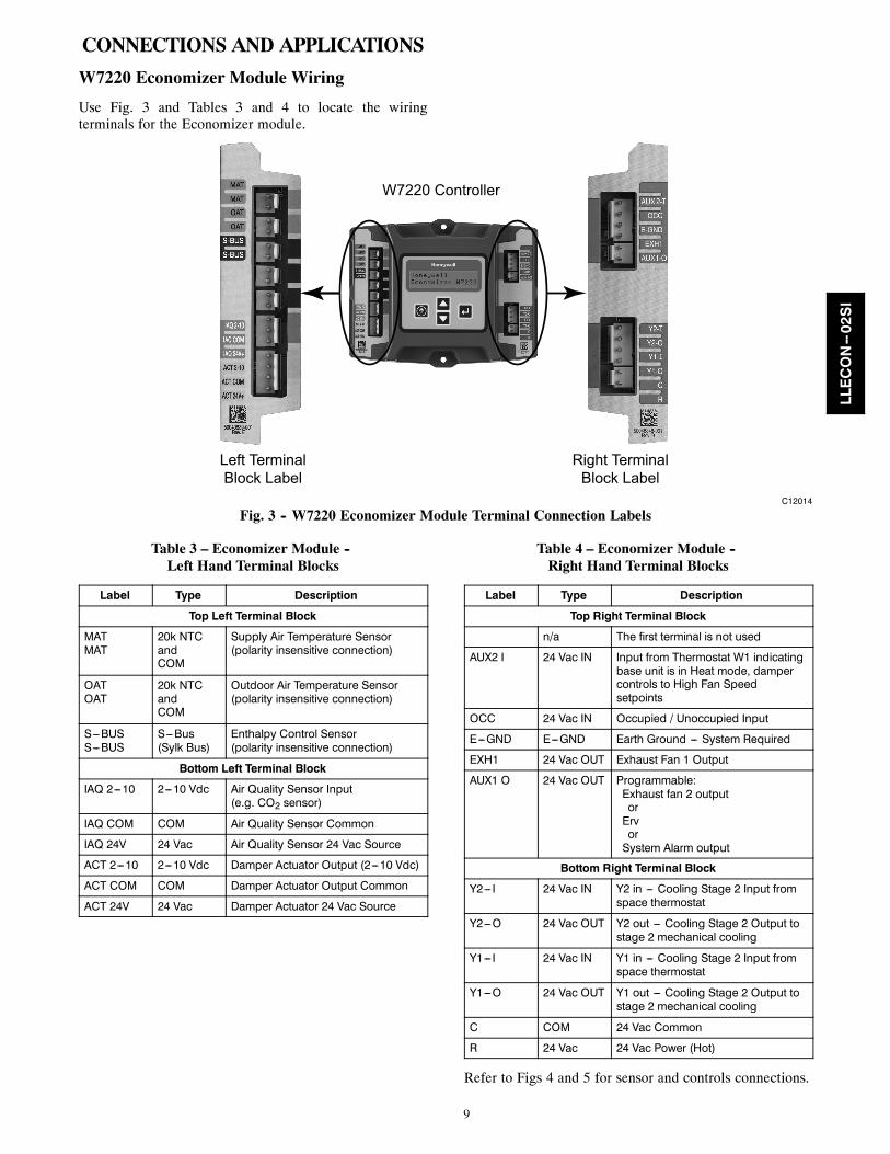
W7220 Economizer Module Wiring
Use Fig. 3 and Tables 3 and 4 to locate the wiringterminals for the Economizer module.
W7220 Controller
Left TerminalBlock Label
Right TerminalBlock Label
C12014
Fig. 3 -- W7220 Economizer Module Terminal Connection Labels
Table 3 – Economizer Module --Left Hand Terminal Blocks
Label Type Description
Top Left Terminal Block
MATMAT
20k NTCandCOM
Supply Air Temperature Sensor(polarity insensitive connection)
OATOAT
20k NTCandCOM
Outdoor Air Temperature Sensor(polarity insensitive connection)
S---BUSS---BUS
S---Bus(Sylk Bus)
Enthalpy Control Sensor(polarity insensitive connection)
Bottom Left Terminal Block
IAQ 2---10 2---10 Vdc Air Quality Sensor Input(e.g. CO2 sensor)
IAQ COM COM Air Quality Sensor Common
IAQ 24V 24 Vac Air Quality Sensor 24 Vac Source
ACT 2---10 2---10 Vdc Damper Actuator Output (2---10 Vdc)
ACT COM COM Damper Actuator Output Common
ACT 24V 24 Vac Damper Actuator 24 Vac Source
Table 4 – Economizer Module --Right Hand Terminal Blocks
Label Type Description
Top Right Terminal Block
n/a The first terminal is not used
AUX2 I 24 Vac IN Input from Thermostat W1 indicatingbase unit is in Heat mode, dampercontrols to High Fan Speedsetpoints
OCC 24 Vac IN Occupied / Unoccupied Input
E---GND E---GND Earth Ground --- System Required
EXH1 24 Vac OUT Exhaust Fan 1 Output
AUX1 O 24 Vac OUT Programmable:Exhaust fan 2 outputorErvorSystem Alarm output
Bottom Right Terminal Block
Y2--- I 24 Vac IN Y2 in --- Cooling Stage 2 Input fromspace thermostat
Y2---O 24 Vac OUT Y2 out --- Cooling Stage 2 Output tostage 2 mechanical cooling
Y1--- I 24 Vac IN Y1 in --- Cooling Stage 2 Input fromspace thermostat
Y1---O 24 Vac OUT Y1 out --- Cooling Stage 2 Output tostage 2 mechanical cooling
C COM 24 Vac Common
R 24 Vac 24 Vac Power (Hot)
Refer to Figs 4 and 5 for sensor and controls connections.
LLECON--02SI
10
POWER EXHAUST RELAY
TSTAT W1
OCCUPANCY --- TSTAT G
GROUND
COMP 2
24-V POWER
TSTAT Y2
TSTAT Y1
COMP 1
24-V COM
BRN
ORN
PNK
VIO
GRA
GRA
BLK
BLU
BLK
BLU
MAT
MAT
OAT
OAT
S - BUS
S - BUS
IAQ - 2 - 10
IAQ COM
IAQ 24V+
ACT - 2 - 10
ACT COM
ACT 24V+
1
2
1
2
1
2
1
2
3
1
2
3
4
WHT
BLK
GRN/YEL
VIO
6
5
4
3
2
1
YEL
ORN
BLU
GRA
BRN
RED
6
5
4
3
2
1
SD- O/B
OCC
EXH 1
AUX
E- GND
Y2 - 1
Y1 - 1
Y1 - 0
C
R
Y2 - 0
W7220CONTROLlER
W1
BLU
EG
RAY
OAT*20-K OHMPNO HH79NZ007
SAT20-K OHMPNO HH79NZ007
CO2 SENSOR
* IF NO ENTHALPY SENSOR CONNECTED
C12165
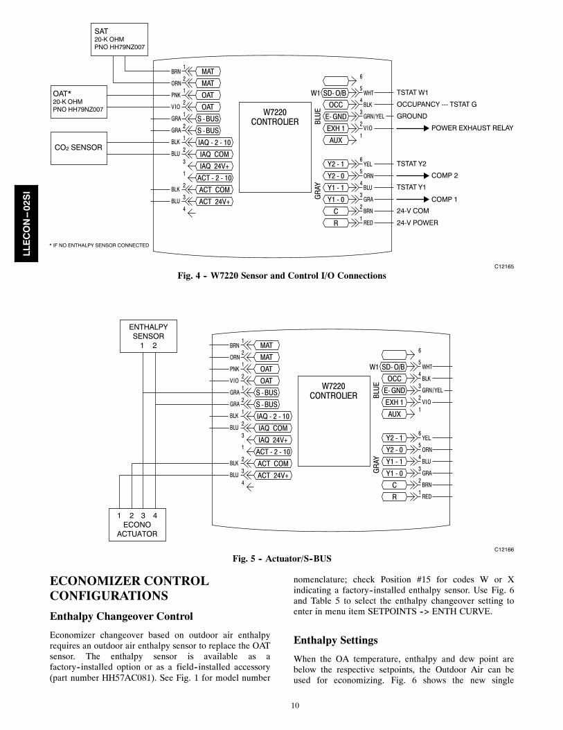
Fig. 4 -- W7220 Sensor and Control I/O Connections
BRN
ORN
PNK
VIO
GRA
GRA
BLK
BLU
BLK
BLU
MAT
MAT
OAT
OAT
S - BUS
S - BUS
IAQ - 2 - 10
IAQ COM
IAQ 24V+
ACT - 2 - 10
ACT COM
ACT 24V+
1
2
1
2
1
2
1
2
3
1
2
3
4
WHT
BLK
GRN/YEL
VIO
6
5
4
3
2
1
YEL
ORN
BLU
GRA
BRN
RED
6
5
4
3
2
1
SD- O/B
OCC
EXH 1
AUX
E- GND
Y2 - 1
Y1 - 1
Y1 - 0
C
R
Y2 - 0
W7220CONTROLlER
W1BL
UE
GR
AY
1 2 3 4ECONO
ACTUATOR
ENTHALPYSENSOR
1 2
C12166
Fig. 5 -- Actuator/S--BUS
ECONOMIZER CONTROLCONFIGURATIONS
Enthalpy Changeover Control
Economizer changeover based on outdoor air enthalpyrequires an outdoor air enthalpy sensor to replace the OATsensor. The enthalpy sensor is available as afactory--installed option or as a field--installed accessory(part number HH57AC081). See Fig. 1 for model number
nomenclature; check Position #15 for codes W or Xindicating a factory--installed enthalpy sensor. Use Fig. 6and Table 5 to select the enthalpy changeover setting toenter in menu item SETPOINTS --> ENTH CURVE.
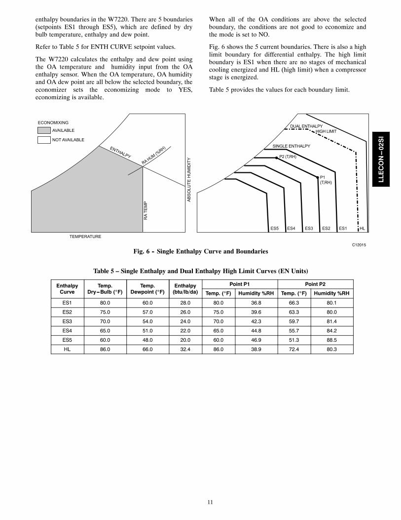
Enthalpy Settings
When the OA temperature, enthalpy and dew point arebelow the respective setpoints, the Outdoor Air can beused for economizing. Fig. 6 shows the new single
LLECON--02SI
11
enthalpy boundaries in the W7220. There are 5 boundaries(setpoints ES1 through ES5), which are defined by drybulb temperature, enthalpy and dew point.
Refer to Table 5 for ENTH CURVE setpoint values.
The W7220 calculates the enthalpy and dew point usingthe OA temperature and humidity input from the OAenthalpy sensor. When the OA temperature, OA humidityand OA dew point are all below the selected boundary, theeconomizer sets the economizing mode to YES,economizing is available.
When all of the OA conditions are above the selectedboundary, the conditions are not good to economize andthe mode is set to NO.
Fig. 6 shows the 5 current boundaries. There is also a highlimit boundary for differential enthalpy. The high limitboundary is ES1 when there are no stages of mechanicalcooling energized and HL (high limit) when a compressorstage is energized.
Table 5 provides the values for each boundary limit.
TEMPERATURE
ENTHALPY
RA
TEM
P AB
SO
LUTE
HU
MID
ITY
ECONOMIXING
AVAILABLE
NOT AVAILABLE
ES5 ES4 ES3 ES2 ES1 HL
DUAL ENTHALPYHIGH LIMIT
SINGLE ENTHALPY
P2 (T,RH)
P1(T,RH)
RA HUM (%RH)
C12015
Fig. 6 -- Single Enthalpy Curve and Boundaries
Table 5 – Single Enthalpy and Dual Enthalpy High Limit Curves (EN Units)
EnthalpyCurve
Temp.Dry---Bulb (_F)
Temp.Dewpoint (_F)
Enthalpy(btu/lb/da)
Point P1 Point P2
Temp. (_F) Humidity %RH Temp. (_F) Humidity %RH
ES1 80.0 60.0 28.0 80.0 36.8 66.3 80.1
ES2 75.0 57.0 26.0 75.0 39.6 63.3 80.0
ES3 70.0 54.0 24.0 70.0 42.3 59.7 81.4
ES4 65.0 51.0 22.0 65.0 44.8 55.7 84.2
ES5 60.0 48.0 20.0 60.0 46.9 51.3 88.5
HL 86.0 66.0 32.4 86.0 38.9 72.4 80.3
LLECON--02SI
12
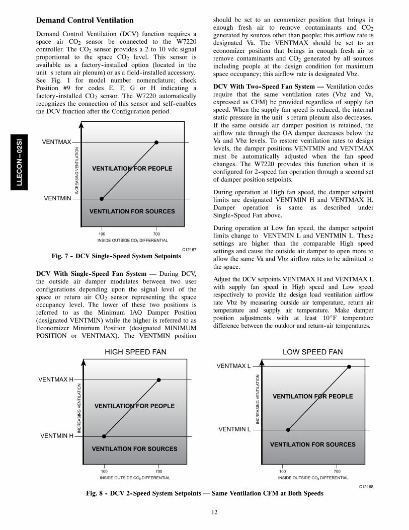
Demand Control Ventilation
Demand Control Ventilation (DCV) function requires aspace air CO2 sensor be connected to the W7220controller. The CO2 sensor provides a 2 to 10 vdc signalproportional to the space CO2 level. This sensor isavailable as a factory--installed option (located in theunit�s return air plenum) or as a field--installed accessory.See Fig. 1 for model number nomenclature; checkPosition #9 for codes E, F, G or H indicating afactory--installed CO2 sensor. The W7220 automaticallyrecognizes the connection of this sensor and self--enablesthe DCV function after the Configuration period.
VENTILATION FOR PEOPLE
VENTILATION FOR SOURCES
INCR
EASI
NG V
ENTI
LATI
ON
VENTMAX
VENTMIN
100 700INSIDE OUTSIDE CO2 DIFFERENTIAL
C12167
Fig. 7 -- DCV Single--Speed System Setpoints
DCV With Single--Speed Fan System — During DCV,the outside air damper modulates between two userconfigurations depending upon the signal level of thespace or return air CO2 sensor representing the spaceoccupancy level. The lower of these two positions isreferred to as the Minimum IAQ Damper Position(designated VENTMIN) while the higher is referred to asEconomizer Minimum Position (designated MINIMUMPOSITION or VENTMAX). The VENTMIN position
should be set to an economizer position that brings inenough fresh air to remove contaminants and CO2generated by sources other than people; this airflow rate isdesignated Va. The VENTMAX should be set to aneconomizer position that brings in enough fresh air toremove contaminants and CO2 generated by all sourcesincluding people at the design condition for maximumspace occupancy; this airflow rate is designated Vbz.
DCV With Two--Speed Fan System — Ventilation codesrequire that the same ventilation rates (Vbz and Va,expressed as CFM) be provided regardless of supply fanspeed. When the supply fan speed is reduced, the internalstatic pressure in the unit�s return plenum also decreases.If the same outside air damper position is retained, theairflow rate through the OA damper decreases below theVa and Vbz levels. To restore ventilation rates to designlevels, the damper positions VENTMIN and VENTMAXmust be automatically adjusted when the fan speedchanges. The W7220 provides this function when it isconfigured for 2--speed fan operation through a second setof damper position setpoints.
During operation at High fan speed, the damper setpointlimits are designated VENTMIN H and VENTMAX H.Damper operation is same as described underSingle--Speed Fan above.
During operation at Low fan speed, the damper setpointlimits change to VENTMIN L and VENTMIN L. Thesesettings are higher than the comparable High speedsettings and cause the outside air damper to open more toallow the same Va and Vbz airflow rates to be admitted tothe space.
Adjust the DCV setpoints VENTMAX H and VENTMAX Lwith supply fan speed in High speed and Low speedrespectively to provide the design load ventilation airflowrate Vbz by measuring outside air temperature, return airtemperature and supply air temperature. Make damperposition adjustments with at least 10_F temperaturedifference between the outdoor and return--air temperatures.
VENTILATION FOR PEOPLE
VENTILATION FOR SOURCES
INC
REA
SIN
G V
ENTI
LATI
ON
VENTMAX H
VENTMIN H
100 700INSIDE OUTSIDE CO2 DIFFERENTIAL
VENTILATION FOR PEOPLE
VENTILATION FOR SOURCES
INC
REA
SIN
G V
ENTI
LATI
ON
VENTMAX L
VENTMIN L
100 700INSIDE OUTSIDE CO2 DIFFERENTIAL
HIGH SPEED FAN LOW SPEED FAN
C12168
Fig. 8 -- DCV 2--Speed System Setpoints — Same Ventilation CFM at Both Speeds
LLECON--02SI
13
To determine the damper setpoint position, perform thefollowing procedure for each condition setpoint, withmechanical cooling OFF:
Calculate the appropriate supply air temperature using thefollowing formula:
TS = (TO x Vbz/CFM) + TR x (CFM – Vbz)/CFM
TS = Supply Air TemperatureTO = Outdoor Air TemperatureVbz = Design Maximum Ventilation CFMrCFM= Unit Supply Airflow RateTR = Return Air Temperature
As an example:
Unit Airflow Rate at High Speed is 4000 CFMVentilation CFM at design occupancy Vbz is 1200 CFMTO = 60 FTR = 75 F
Required TS = 60 x (1200/4000) + 75 x (4000 – 1200/4000)= 60 x 0.30 + 75 x 0.70 = 18.0 + 52.5= 70.5
At the W7220 keypad, enter the parameter SETUP -->VENTMAX H and adjust the setpoint value until theobserved Supply Air Temperature (MA TEMP) reaches70.5. Press the “Enter” key to save this setpoint tocontroller memory.
When determining VENTMIN setpoints, substitute thevalue for Va in place of Vbz in the formula.
DCV Setpoint — The SETPOINTS parameter DCV SETdefines the space CO2 level above which the DCV modebegins to open the outside air damper beyond itsVENTMIN ventilation lower limit. This setpoint shouldbe a minimum of 100 ppm greater than the outdoorambient CO2 level to ensure the outside air will becapable of diluting the space CO2 level. A typical valuefor outdoor CO2 is 400 ppm; adjust the setpoint DCV SETto 500 ppm if outdoor CO2 level is not known. Thefactory default value for DCV SET is 1100 ppm.
Economizer Occupancy Control
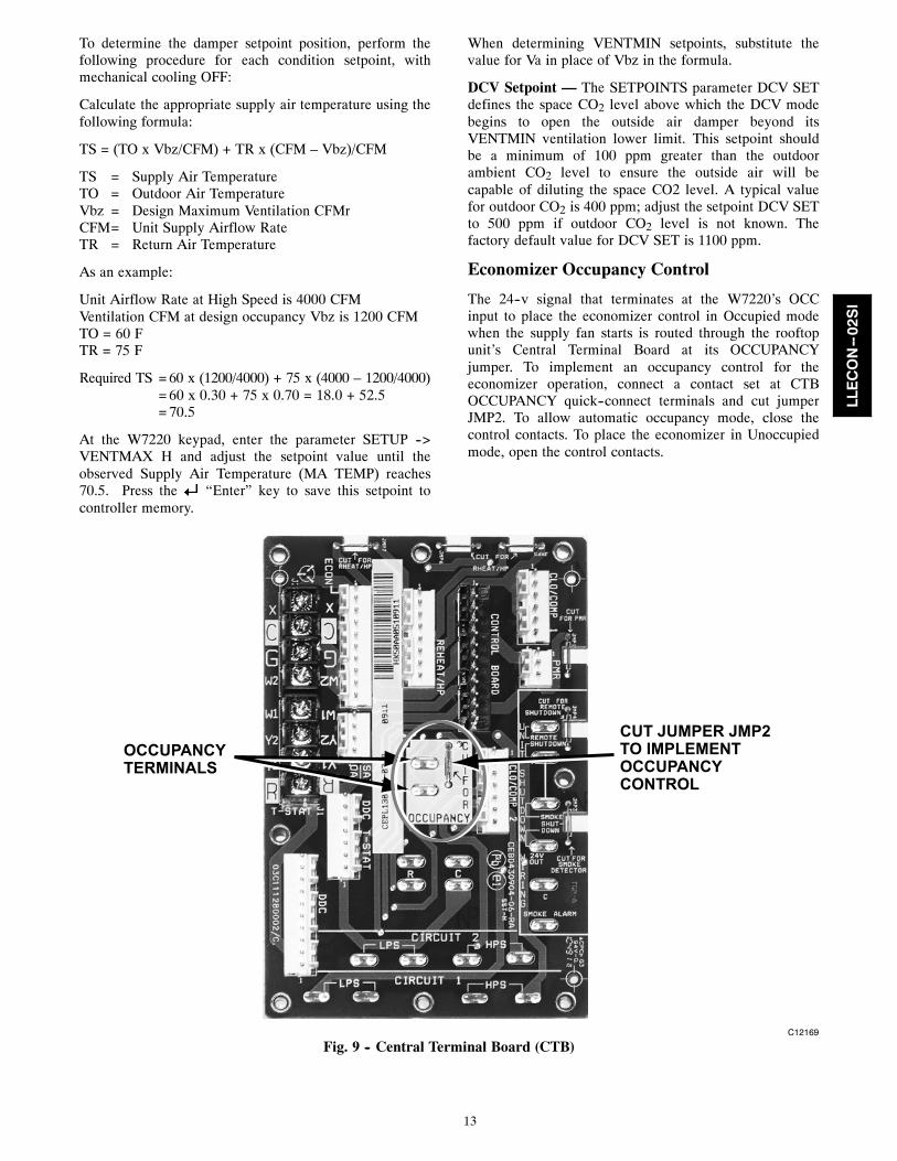
The 24--v signal that terminates at the W7220’s OCCinput to place the economizer control in Occupied modewhen the supply fan starts is routed through the rooftopunit’s Central Terminal Board at its OCCUPANCYjumper. To implement an occupancy control for theeconomizer operation, connect a contact set at CTBOCCUPANCY quick--connect terminals and cut jumperJMP2. To allow automatic occupancy mode, close thecontrol contacts. To place the economizer in Unoccupiedmode, open the control contacts.
OCCUPANCY TERMINALS
CUT JUMPER JMP2TO IMPLEMENTOCCUPANCYCONTROL
C12169
Fig. 9 -- Central Terminal Board (CTB)
LLECON--02SI
14
HARDWARE
Actuators
The Economizer X damper actuators are direct--coupledtypes with spring--return. Power is 24--v from the W7220outputs. Range of rotation is 95--degrees; timing forfull--range movement is 90 seconds to drive open innormal operation, 30 seconds in Test Mode and 25seconds for spring return.
These actuators are S--bus enabled. The S--bus is aproprietary local equipment network that connects theW7220 controller, one S--enabled actuator and up to threeS--type enthalpy sensors on a two--wire communicationnetwork. The S--bus is polarity--insensitive. Devicesattached to the S-- bus are automatically recognized by thecontroller.
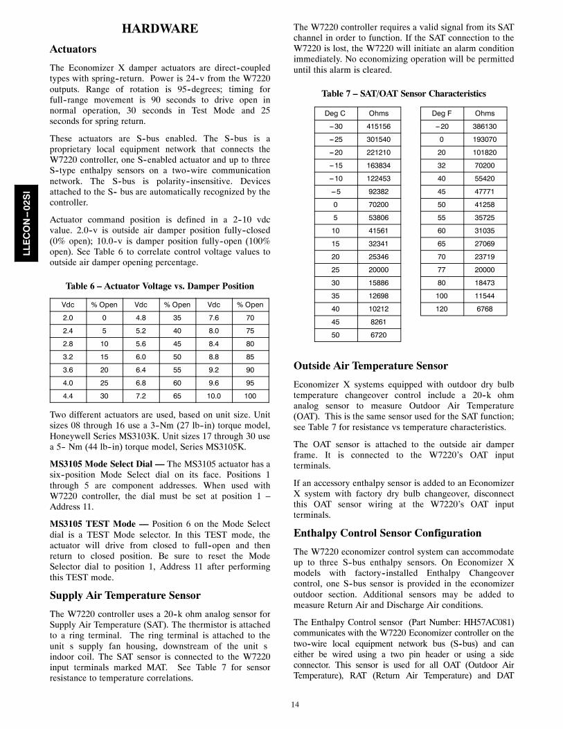
Actuator command position is defined in a 2--10 vdcvalue. 2.0--v is outside air damper position fully--closed(0% open); 10.0--v is damper position fully--open (100%open). See Table 6 to correlate control voltage values tooutside air damper opening percentage.
Table 6 – Actuator Voltage vs. Damper Position
Vdc % Open Vdc % Open Vdc % Open
2.0 0 4.8 35 7.6 70
2.4 5 5.2 40 8.0 75
2.8 10 5.6 45 8.4 80
3.2 15 6.0 50 8.8 85
3.6 20 6.4 55 9.2 90
4.0 25 6.8 60 9.6 95
4.4 30 7.2 65 10.0 100
Two different actuators are used, based on unit size. Unitsizes 08 through 16 use a 3--Nm (27 lb--in) torque model,Honeywell Series MS3103K. Unit sizes 17 through 30 usea 5-- Nm (44 lb--in) torque model, Series MS3105K.
MS3105 Mode Select Dial — The MS3105 actuator has asix--position Mode Select dial on its face. Positions 1through 5 are component addresses. When used withW7220 controller, the dial must be set at position 1 –Address 11.
MS3105 TEST Mode — Position 6 on the Mode Selectdial is a TEST Mode selector. In this TEST mode, theactuator will drive from closed to full--open and thenreturn to closed position. Be sure to reset the ModeSelector dial to position 1, Address 11 after performingthis TEST mode.
Supply Air Temperature Sensor
The W7220 controller uses a 20--k ohm analog sensor forSupply Air Temperature (SAT). The thermistor is attachedto a ring terminal. The ring terminal is attached to theunit�s supply fan housing, downstream of the unit�sindoor coil. The SAT sensor is connected to the W7220input terminals marked MAT. See Table 7 for sensorresistance to temperature correlations.
The W7220 controller requires a valid signal from its SATchannel in order to function. If the SAT connection to theW7220 is lost, the W7220 will initiate an alarm conditionimmediately. No economizing operation will be permitteduntil this alarm is cleared.
Table 7 – SAT/OAT Sensor Characteristics
Deg C Ohms Deg F Ohms
---30 415156 ---20 386130
---25 301540 0 193070
---20 221210 20 101820
---15 163834 32 70200
---10 122453 40 55420
---5 92382 45 47771
0 70200 50 41258
5 53806 55 35725
10 41561 60 31035
15 32341 65 27069
20 25346 70 23719
25 20000 77 20000
30 15886 80 18473
35 12698 100 11544
40 10212 120 6768
45 8261
50 6720
Outside Air Temperature Sensor
Economizer X systems equipped with outdoor dry bulbtemperature changeover control include a 20--k ohmanalog sensor to measure Outdoor Air Temperature(OAT). This is the same sensor used for the SAT function;see Table 7 for resistance vs temperature characteristics.
The OAT sensor is attached to the outside air damperframe. It is connected to the W7220’s OAT inputterminals.
If an accessory enthalpy sensor is added to an EconomizerX system with factory dry bulb changeover, disconnectthis OAT sensor wiring at the W7220’s OAT inputterminals.
Enthalpy Control Sensor Configuration
The W7220 economizer control system can accommodateup to three S--bus enthalpy sensors. On Economizer Xmodels with factory--installed Enthalpy Changeovercontrol, one S--bus sensor is provided in the economizeroutdoor section. Additional sensors may be added tomeasure Return Air and Discharge Air conditions.
The Enthalpy Control sensor (Part Number: HH57AC081)communicates with the W7220 Economizer controller on thetwo--wire local equipment network bus (S--bus) and caneither be wired using a two pin header or using a sideconnector. This sensor is used for all OAT (Outdoor AirTemperature), RAT (Return Air Temperature) and DAT
LLECON--02SI
15
(Discharge Air Temperature), depending on how its threeposition DIP switch is set.
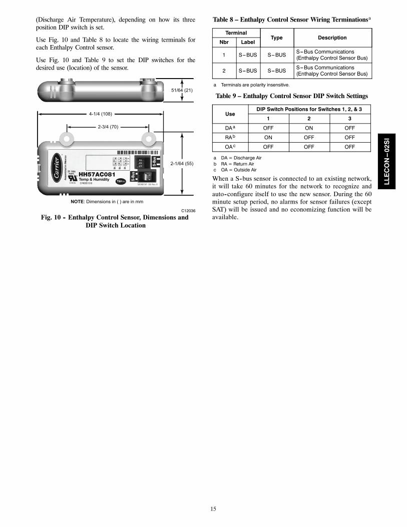
Use Fig. 10 and Table 8 to locate the wiring terminals foreach Enthalpy Control sensor.
Use Fig. 10 and Table 9 to set the DIP switches for thedesired use (location) of the sensor.
2-1/64 (55)
51/64 (21)
4-1/4 (108)
2-3/4 (70)
NOTE: Dimensions in ( ) are in mm
C12036
Fig. 10 -- Enthalpy Control Sensor, Dimensions andDIP Switch Location
Table 8 – Enthalpy Control Sensor Wiring Terminationsa
TerminalType Description
Nbr Label
1 S---BUS S---BUS S---Bus Communications(Enthalpy Control Sensor Bus)
2 S---BUS S---BUS S---Bus Communications(Enthalpy Control Sensor Bus)
a Terminals are polarity insensitive.
Table 9 – Enthalpy Control Sensor DIP Switch Settings
UseDIP Switch Positions for Switches 1, 2, & 3
1 2 3
DAa OFF ON OFF
RAb ON OFF OFF
OAc OFF OFF OFF
a DA = Discharge Airb RA = Return Airc OA = Outside Air
When a S--bus sensor is connected to an existing network,it will take 60 minutes for the network to recognize andauto--configure itself to use the new sensor. During the 60minute setup period, no alarms for sensor failures (exceptSAT) will be issued and no economizing function will beavailable.
LLECON--02SI
16
OPERATING SEQUENCES
Staged Air Volume (2--Speed) Fan Motor
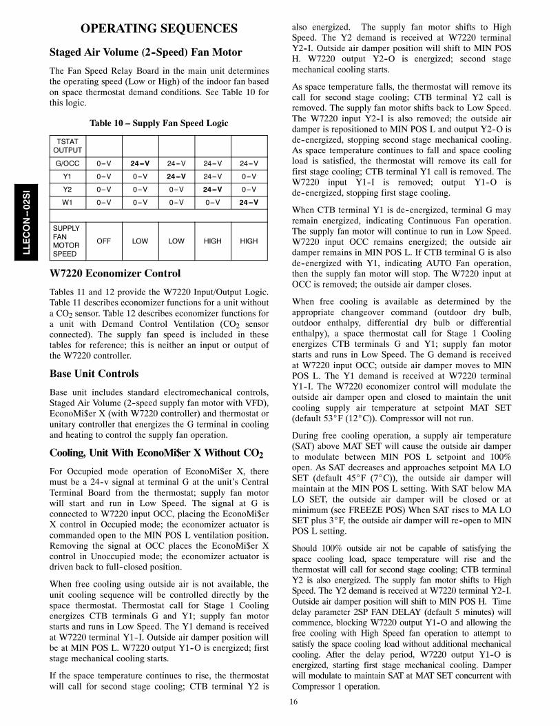
The Fan Speed Relay Board in the main unit determinesthe operating speed (Low or High) of the indoor fan basedon space thermostat demand conditions. See Table 10 forthis logic.
Table 10 – Supply Fan Speed Logic
TSTATOUTPUT
G/OCC 0---V 24---V 24---V 24---V 24---V
Y1 0---V 0---V 24---V 24---V 0---V
Y2 0---V 0---V 0---V 24---V 0---V
W1 0---V 0---V 0---V 0---V 24---V
SUPPLYFANMOTORSPEED
OFF LOW LOW HIGH HIGH
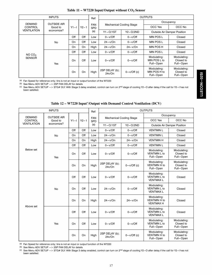
W7220 Economizer Control
Tables 11 and 12 provide the W7220 Input/Output Logic.Table 11 describes economizer functions for a unit withouta CO2 sensor. Table 12 describes economizer functions fora unit with Demand Control Ventilation (CO2 sensorconnected). The supply fan speed is included in thesetables for reference; this is neither an input or output ofthe W7220 controller.
Base Unit Controls
Base unit includes standard electromechanical controls,Staged Air Volume (2--speed supply fan motor with VFD),EconoMi$er X (with W7220 controller) and thermostat orunitary controller that energizes the G terminal in coolingand heating to control the supply fan operation.
Cooling, Unit With EconoMi$er X Without CO2
For Occupied mode operation of EconoMi$er X, theremust be a 24--v signal at terminal G at the unit’s CentralTerminal Board from the thermostat; supply fan motorwill start and run in Low Speed. The signal at G isconnected to W7220 input OCC, placing the EconoMi$erX control in Occupied mode; the economizer actuator iscommanded open to the MIN POS L ventilation position.Removing the signal at OCC places the EconoMi$er Xcontrol in Unoccupied mode; the economizer actuator isdriven back to full--closed position.
When free cooling using outside air is not available, theunit cooling sequence will be controlled directly by thespace thermostat. Thermostat call for Stage 1 Coolingenergizes CTB terminals G and Y1; supply fan motorstarts and runs in Low Speed. The Y1 demand is receivedat W7220 terminal Y1--I. Outside air damper position willbe at MIN POS L. W7220 output Y1--O is energized; firststage mechanical cooling starts.
If the space temperature continues to rise, the thermostatwill call for second stage cooling; CTB terminal Y2 is
also energized. The supply fan motor shifts to HighSpeed. The Y2 demand is received at W7220 terminalY2--I. Outside air damper position will shift to MIN POSH. W7220 output Y2--O is energized; second stagemechanical cooling starts.
As space temperature falls, the thermostat will remove itscall for second stage cooling; CTB terminal Y2 call isremoved. The supply fan motor shifts back to Low Speed.The W7220 input Y2--I is also removed; the outside airdamper is repositioned to MIN POS L and output Y2--O isde--energized, stopping second stage mechanical cooling.As space temperature continues to fall and space coolingload is satisfied, the thermostat will remove its call forfirst stage cooling; CTB terminal Y1 call is removed. TheW7220 input Y1--I is removed; output Y1--O isde--energized, stopping first stage cooling.
When CTB terminal Y1 is de--energized, terminal G mayremain energized, indicating Continuous Fan operation.The supply fan motor will continue to run in Low Speed.W7220 input OCC remains energized; the outside airdamper remains in MIN POS L. If CTB terminal G is alsode--energized with Y1, indicating AUTO Fan operation,then the supply fan motor will stop. The W7220 input atOCC is removed; the outside air damper closes.
When free cooling is available as determined by theappropriate changeover command (outdoor dry bulb,outdoor enthalpy, differential dry bulb or differentialenthalpy), a space thermostat call for Stage 1 Coolingenergizes CTB terminals G and Y1; supply fan motorstarts and runs in Low Speed. The G demand is receivedat W7220 input OCC; outside air damper moves to MINPOS L. The Y1 demand is received at W7220 terminalY1--I. The W7220 economizer control will modulate theoutside air damper open and closed to maintain the unitcooling supply air temperature at setpoint MAT SET(default 53_F (12_C)). Compressor will not run.
During free cooling operation, a supply air temperature(SAT) above MAT SET will cause the outside air damperto modulate between MIN POS L setpoint and 100%open. As SAT decreases and approaches setpoint MA LOSET (default 45_F (7_C)), the outside air damper willmaintain at the MIN POS L setting. With SAT below MALO SET, the outside air damper will be closed or atminimum (see FREEZE POS) When SAT rises to MA LOSET plus 3_F, the outside air damper will re--open to MINPOS L setting.
Should 100% outside air not be capable of satisfying thespace cooling load, space temperature will rise and thethermostat will call for second stage cooling; CTB terminalY2 is also energized. The supply fan motor shifts to HighSpeed. The Y2 demand is received at W7220 terminal Y2--I.Outside air damper position will shift to MIN POS H. Timedelay parameter 2SP FAN DELAY (default 5 minutes) willcommence, blocking W7220 output Y1--O and allowing thefree cooling with High Speed fan operation to attempt tosatisfy the space cooling load without additional mechanicalcooling. After the delay period, W7220 output Y1--O isenergized, starting first stage mechanical cooling. Damperwill modulate to maintain SAT at MAT SET concurrent withCompressor 1 operation.
LLECON--02SI
17
Table 11 – W7220 Input/Output without CO2 Sensor
INPUTS Ref:
FANSPD(a)
OUTPUTS
DEMANDCONTROLVENTILATION
OUTSIDE AIRGood toeconomize?
Y1--- I Y2---1Mechanical Cooling Stage
Occupancy
OCC Yes OCC No
Y1---O/1ST Y2---O/2ND Outside Air Damper Position
NO CO2SENSOR
No
Off Off Low 0---v/Off 0---v/Off MIN POS L Closed
On Off Low 24---v/On 0---v/Off MIN POS L Closed
On On High 24---v/On 24---v/On MIN POS H Closed
Yes
Off Off Low 0---v/Off 0---v/Off MIN POS L Closed
On Off Low 0---v/Off 0---v/OffModulating:MIN POS L toFull---Open
Modulating:Closed toFull---Open
On On High 2SP DELAY (b);24v/On 0---v/Off (c)
Modulating:MIN POS H toFull---Open
Modulating:Closed toFull---Open
(a) Fan Speed for reference only; tins is not an input or output function of the W7220(b) See Menu ADV SETUP ---> 2SP FAN DELAY for details(c) See Menu ADV SETUP ---> STG# DLY. With Stage 3 delay enabled, control can turn on 2nd stage of cooling Y2---O after delay if the call for Y2---I has notbeen satisfied.
Table 12 – W7220 Input’/Output with Demand Control Ventilation (DCV)
INPUTS Ref:
FANSPD(a)
OUTPUTS
DEMANDCONTROLVENTILATION
OUTSIDE AIRGood toeconomize?
Y1--- I Y2---1Mechanical Cooling Stage
Occupancy
OCC Yes OCC No
Y1---O/1ST Y2---O/2ND Outside Air Damper Position
Below set
No
Off Off Low 0---v/Off 0---v/Off VENTMIN L Closed
On Off Low 24---v/On 0---v/Off VENTMIN L Closed
On On High 24---v/On 24---v/On VENTMIN H Closed
Yes
Off Off Low 0---v/Off 0---v/Off VENTMIN L Closed
On Off Low 0---v/Off 0---v/OffModulating:VENTMIN L toFull---Open
Modulating:Closed toFull---Open
On On High2SP DELAY (b);24v/On 0---v/Off (c)
Modulating:VENTMIN H toFull---Open
Modulating:Closed toFull---Open
Above set
No
Off Off Low 0---v/Off 0---v/OffModulating:VENTMIN L toVENTMAX L
Closed
On Off Low 24---v/On 0---v/OffModulating:VENTMIN L toVENTMAX L
Closed
On On High 24---v/On 24---v/OnModulating:VENTMIN H toVENTMAX H
Closed
Yes
Off Off Low 0---v/Off 0---v/OffModulating:VENTMIN L toVENTMAX L
Closed
On Off Low 0---v/Off 0---v/OffModulating:VENTMIN L toFull---Open
Modulating:Closed toFull---Open
On On High 2SP DELAY (b);24v/On 0---v/Off (c)
Modulating:VENTMIN H toFull---Open
Modulating:Closed toFull---Open
(a) Fan Speed for reference only; tins is not an input or output function of the W7220(b) See Menu ADV SETUP ---> 2SP FAN DELAY for details(c) See Menu ADV SETUP ---> STG# DLY. With Stage 3 delay enabled, control can turn on 2nd stage of cooling Y2---O after delay if the call for Y2---I has notbeen satisfied.
LLECON--02SI
18
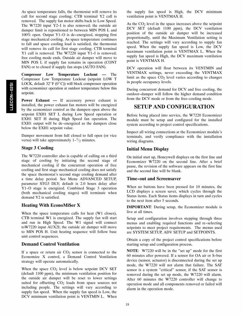
As space temperature falls, the thermostat will remove itscall for second stage cooling; CTB terminal Y2 call isremoved. The supply fan motor shifts back to Low Speed.The W7220 input Y2--I is also removed; the outside airdamper limit is repositioned to between MIN POS L and100% open. Output Y1--O is de--energized, stopping firststage mechanical cooling. As space temperature continuesto fall and space cooling load is satisfied, the thermostatwill remove its call for first stage cooling; CTB terminalY1 call is removed. The W7220 input Y1--I is removed;free cooling mode ends. Outside air damper will move toMIN POS L if supply fan remains in operation (CONTFAN) or to closed if supply fan stops (AUTO FAN).
Compressor Low Temperature Lockout — TheCompressor Low Temperature Lockout (setpoint LOW TLOCK, default 32_F (0_C)) will block compressor operationwith economizer operation at outdoor temperature below thissetpoint.
Power Exhaust — If accessory power exhaust isinstalled, the power exhaust fan motors will be energizedby the economizer control as the dampers open above thesetpoint EXH1 SET L during Low Speed operation orEXH1 SET H during High Speed fan operation. TheEXH1 output will be de--energized as the dampers closebelow the EXH1 setpoint value.
Damper movement from full closed to full open (or viceversa) will take approximately 1--1/2 minutes.
Stage 3 Cooling
The W7220 controller also is capable of calling on a thirdstage of cooling by initiating the second stage ofmechanical cooling if the concurrent operation of freecooling and first stage mechanical cooling does not satisfythe space thermostat’s second stage cooling demand aftera time delay period. See Menu ADVANCED SETUP,parameter STG3 DLY; default is 2.0 hours delay afterY1--O stage is energized. Combined Stage 3 operation(both mechanical cooling stages) will terminate whendemand Y2 is satisfied.
Heating With EconoMi$er X
When the space temperature calls for heat (W1 closes),CTB terminal W1 is energized. The supply fan will startand run in High Speed. The W1 signal will connecttoW7220 input AUX2I; the outside air damper will moveto MIN POS H. Unit heating sequence will follow baseunit control sequences.
Demand Control Ventilation
If a space or return air CO2 sensor is connected to theEconomize X control, a Demand Control Ventilationstrategy will operate automatically.
When the space CO2 level is below setpoint DCV SET(default 1100 ppm), the minimum ventilation position forthe outside air damper will be reset to lower settingssuited for offsetting CO2 loads from space sources notincluding people. The settings will vary according tosupply fan speed. When the supply fan speed is Low, theDCV minimum ventilation point is VENTMIN L. When
the supply fan speed is High, the DCV minimumventilation point is VENTMAX H.
As the CO2 level in the space increases above the setpointDCV SET (default 1100 ppm), the DCV ventilationposition of the outside air damper will be increasedproportionally, until the Maximum Ventilation setting isreached. The settings will vary according to supply fanspeed. When the supply fan speed is Low, the DCVmaximum ventilation point is VENTMAX L. When thesupply fan speed is High, the DCV maximum ventilationpoint is VENTMAX H.
DCV operation will float between its VENTMIN andVENTMAX settings, never exceeding the VENTMAXlimit as the space CO2 level varies according to changesin people occupancy levels.
During concurrent demand for DCV and free cooling, theoutdoor--damper will follow the higher demand conditionfrom the DCV mode or from the free--cooling mode.
SETUP AND CONFIGURATION
Before being placed into service, the W7220 Economizermodule must be setup and configured for the installedsystem according to project control specifications.
Inspect all wiring connections at the Economizer module’sterminals, and verify compliance with the installationwiring diagrams.
Initial Menu Display
On initial start up, Honeywell displays on the first line andEconomizer W7220 on the second line. After a briefpause, the revision of the software appears on the first lineand the second line will be blank.
Time--out and Screensaver
When no buttons have been pressed for 10 minutes, theLCD displays a screen saver, which cycles through theStatus items. Each Status items displays in turn and cyclesto the next item after 5 seconds.
IMPORTANT: During setup, the Economizer module islive at all times.
Setup and configuration involves stepping through threemenus and enabling required functions and re--selectingsetpoints to meet project requirements. The menus usedare SYSTEM SETUP, ADV SETUP and SETPOINTS.
Obtain a copy of the project control specifications beforestarting setup and configuration process.
NOTE: W7220 will be in the ”set up” mode for the first60 minutes after powered. If a sensor for OA air or S--busdevice (sensor, actuator) is disconnected during the set upmode, the W7220 will not alarm that failure. The SATsensor is a system ”critical” sensor, if the SAT sensor isremoved during the set up mode, the W7220 will alarm.After 60 minutes the W7220 controller will change tooperation mode and all components removed or failed willalarm in the operation mode.
LLECON--02SI
19
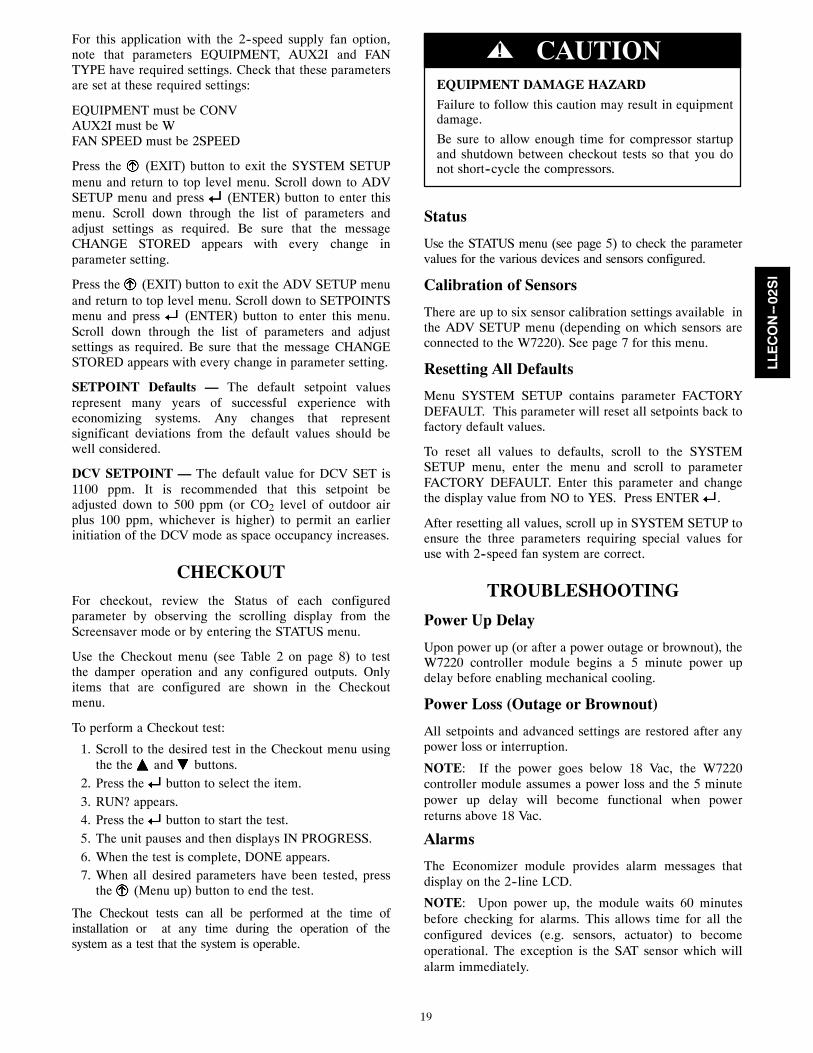
For this application with the 2--speed supply fan option,note that parameters EQUIPMENT, AUX2I and FANTYPE have required settings. Check that these parametersare set at these required settings:
EQUIPMENT must be CONVAUX2I must be WFAN SPEED must be 2SPEED
Press the (EXIT) button to exit the SYSTEM SETUPmenu and return to top level menu. Scroll down to ADVSETUP menu and press (ENTER) button to enter thismenu. Scroll down through the list of parameters andadjust settings as required. Be sure that the messageCHANGE STORED appears with every change inparameter setting.
Press the (EXIT) button to exit the ADV SETUP menuand return to top level menu. Scroll down to SETPOINTSmenu and press (ENTER) button to enter this menu.Scroll down through the list of parameters and adjustsettings as required. Be sure that the message CHANGESTORED appears with every change in parameter setting.
SETPOINT Defaults — The default setpoint valuesrepresent many years of successful experience witheconomizing systems. Any changes that representsignificant deviations from the default values should bewell considered.
DCV SETPOINT — The default value for DCV SET is1100 ppm. It is recommended that this setpoint beadjusted down to 500 ppm (or CO2 level of outdoor airplus 100 ppm, whichever is higher) to permit an earlierinitiation of the DCV mode as space occupancy increases.
CHECKOUT
For checkout, review the Status of each configuredparameter by observing the scrolling display from theScreensaver mode or by entering the STATUS menu.
Use the Checkout menu (see Table 2 on page 8) to testthe damper operation and any configured outputs. Onlyitems that are configured are shown in the Checkoutmenu.
To perform a Checkout test:
1. Scroll to the desired test in the Checkout menu usingthe the and buttons.
2. Press the button to select the item.3. RUN? appears.4. Press the button to start the test.5. The unit pauses and then displays IN PROGRESS.6. When the test is complete, DONE appears.7. When all desired parameters have been tested, press
the (Menu up) button to end the test.
The Checkout tests can all be performed at the time ofinstallation or at any time during the operation of thesystem as a test that the system is operable.
EQUIPMENT DAMAGE HAZARD
Failure to follow this caution may result in equipmentdamage.
Be sure to allow enough time for compressor startupand shutdown between checkout tests so that you donot short--cycle the compressors.
CAUTION!
Status
Use the STATUS menu (see page 5) to check the parametervalues for the various devices and sensors configured.
Calibration of Sensors
There are up to six sensor calibration settings available inthe ADV SETUP menu (depending on which sensors areconnected to the W7220). See page 7 for this menu.
Resetting All Defaults
Menu SYSTEM SETUP contains parameter FACTORYDEFAULT. This parameter will reset all setpoints back tofactory default values.
To reset all values to defaults, scroll to the SYSTEMSETUP menu, enter the menu and scroll to parameterFACTORY DEFAULT. Enter this parameter and changethe display value from NO to YES. Press ENTER .
After resetting all values, scroll up in SYSTEM SETUP toensure the three parameters requiring special values foruse with 2--speed fan system are correct.
TROUBLESHOOTING
Power Up Delay
Upon power up (or after a power outage or brownout), theW7220 controller module begins a 5 minute power updelay before enabling mechanical cooling.
Power Loss (Outage or Brownout)
All setpoints and advanced settings are restored after anypower loss or interruption.
NOTE: If the power goes below 18 Vac, the W7220controller module assumes a power loss and the 5 minutepower up delay will become functional when powerreturns above 18 Vac.
Alarms
The Economizer module provides alarm messages thatdisplay on the 2--line LCD.
NOTE: Upon power up, the module waits 60 minutesbefore checking for alarms. This allows time for all theconfigured devices (e.g. sensors, actuator) to becomeoperational. The exception is the SAT sensor which willalarm immediately.
LLECON--02SI
20
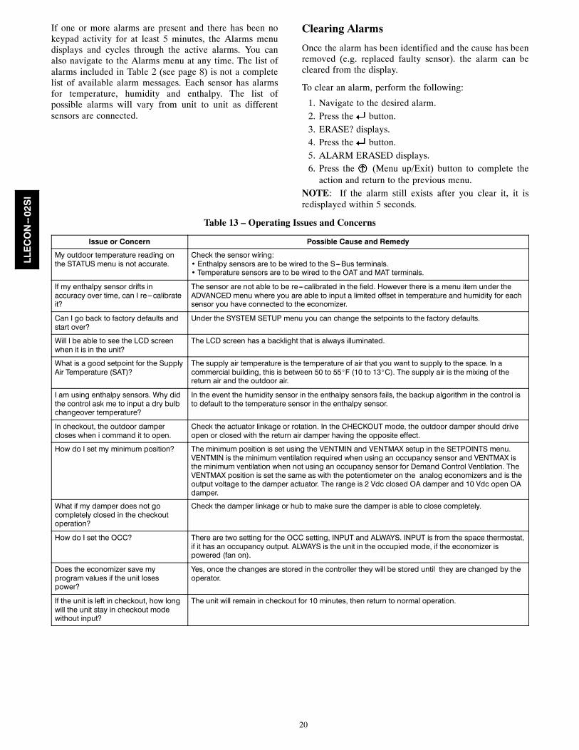
If one or more alarms are present and there has been nokeypad activity for at least 5 minutes, the Alarms menudisplays and cycles through the active alarms. You canalso navigate to the Alarms menu at any time. The list ofalarms included in Table 2 (see page 8) is not a completelist of available alarm messages. Each sensor has alarmsfor temperature, humidity and enthalpy. The list ofpossible alarms will vary from unit to unit as differentsensors are connected.
Clearing Alarms
Once the alarm has been identified and the cause has beenremoved (e.g. replaced faulty sensor). the alarm can becleared from the display.
To clear an alarm, perform the following:
1. Navigate to the desired alarm.2. Press the button.3. ERASE? displays.4. Press the button.5. ALARM ERASED displays.6. Press the (Menu up/Exit) button to complete the
action and return to the previous menu.NOTE: If the alarm still exists after you clear it, it isredisplayed within 5 seconds.
Table 13 – Operating Issues and Concerns
Issue or Concern Possible Cause and Remedy
My outdoor temperature reading onthe STATUS menu is not accurate.
Check the sensor wiring:• Enthalpy sensors are to be wired to the S---Bus terminals.• Temperature sensors are to be wired to the OAT and MAT terminals.
If my enthalpy sensor drifts inaccuracy over time, can I re---calibrateit?
The sensor are not able to be re---calibrated in the field. However there is a menu item under theADVANCED menu where you are able to input a limited offset in temperature and humidity for eachsensor you have connected to the economizer.
Can I go back to factory defaults andstart over?
Under the SYSTEM SETUP menu you can change the setpoints to the factory defaults.
Will I be able to see the LCD screenwhen it is in the unit?
The LCD screen has a backlight that is always illuminated.
What is a good setpoint for the SupplyAir Temperature (SAT)?
The supply air temperature is the temperature of air that you want to supply to the space. In acommercial building, this is between 50 to 55_F (10 to 13_C). The supply air is the mixing of thereturn air and the outdoor air.
I am using enthalpy sensors. Why didthe control ask me to input a dry bulbchangeover temperature?
In the event the humidity sensor in the enthalpy sensors fails, the backup algorithm in the control isto default to the temperature sensor in the enthalpy sensor.
In checkout, the outdoor dampercloses when i command it to open.
Check the actuator linkage or rotation. In the CHECKOUT mode, the outdoor damper should driveopen or closed with the return air damper having the opposite effect.
How do I set my minimum position? The minimum position is set using the VENTMIN and VENTMAX setup in the SETPOINTS menu.VENTMIN is the minimum ventilation required when using an occupancy sensor and VENTMAX isthe minimum ventilation when not using an occupancy sensor for Demand Control Ventilation. TheVENTMAX position is set the same as with the potentiometer on the analog economizers and is theoutput voltage to the damper actuator. The range is 2 Vdc closed OA damper and 10 Vdc open OAdamper.
What if my damper does not gocompletely closed in the checkoutoperation?
Check the damper linkage or hub to make sure the damper is able to close completely.
How do I set the OCC? There are two setting for the OCC setting, INPUT and ALWAYS. INPUT is from the space thermostat,if it has an occupancy output. ALWAYS is the unit in the occupied mode, if the economizer ispowered (fan on).
Does the economizer save myprogram values if the unit losespower?
Yes, once the changes are stored in the controller they will be stored until they are changed by theoperator.
If the unit is left in checkout, how longwill the unit stay in checkout modewithout input?
The unit will remain in checkout for 10 minutes, then return to normal operation.
LLECON--02SI
21
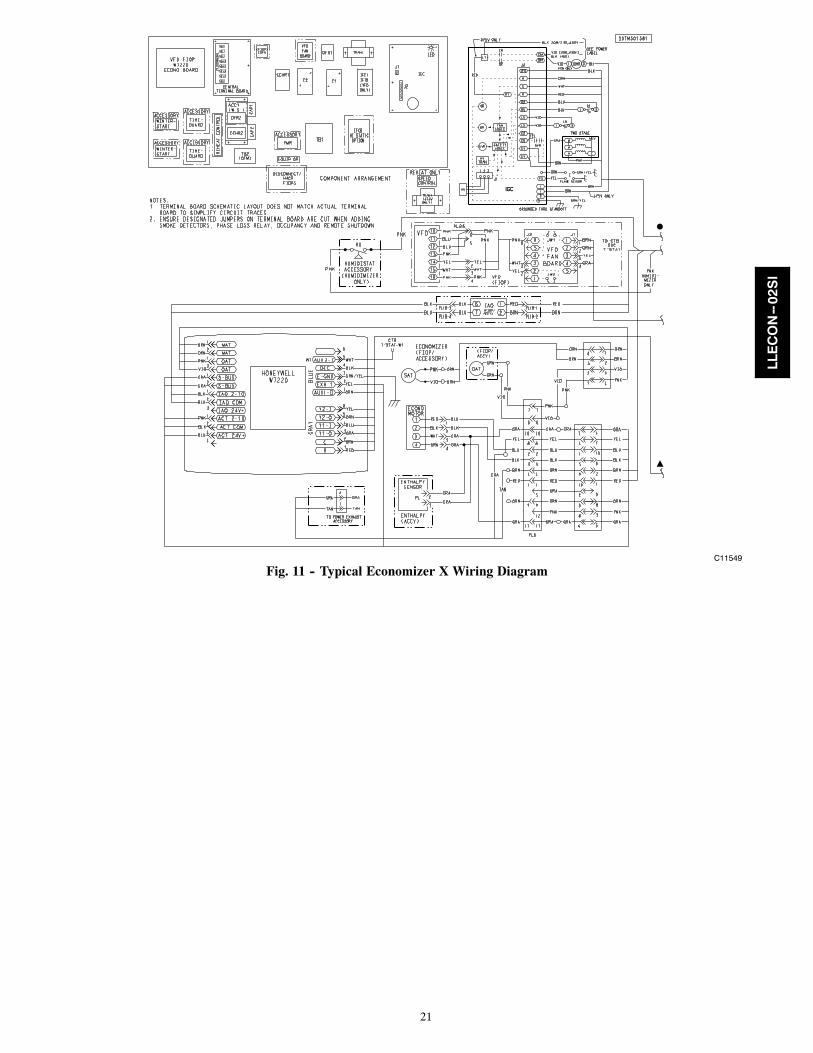
C11549
Fig. 11 -- Typical Economizer X Wiring Diagram
LLECON--02SI
22
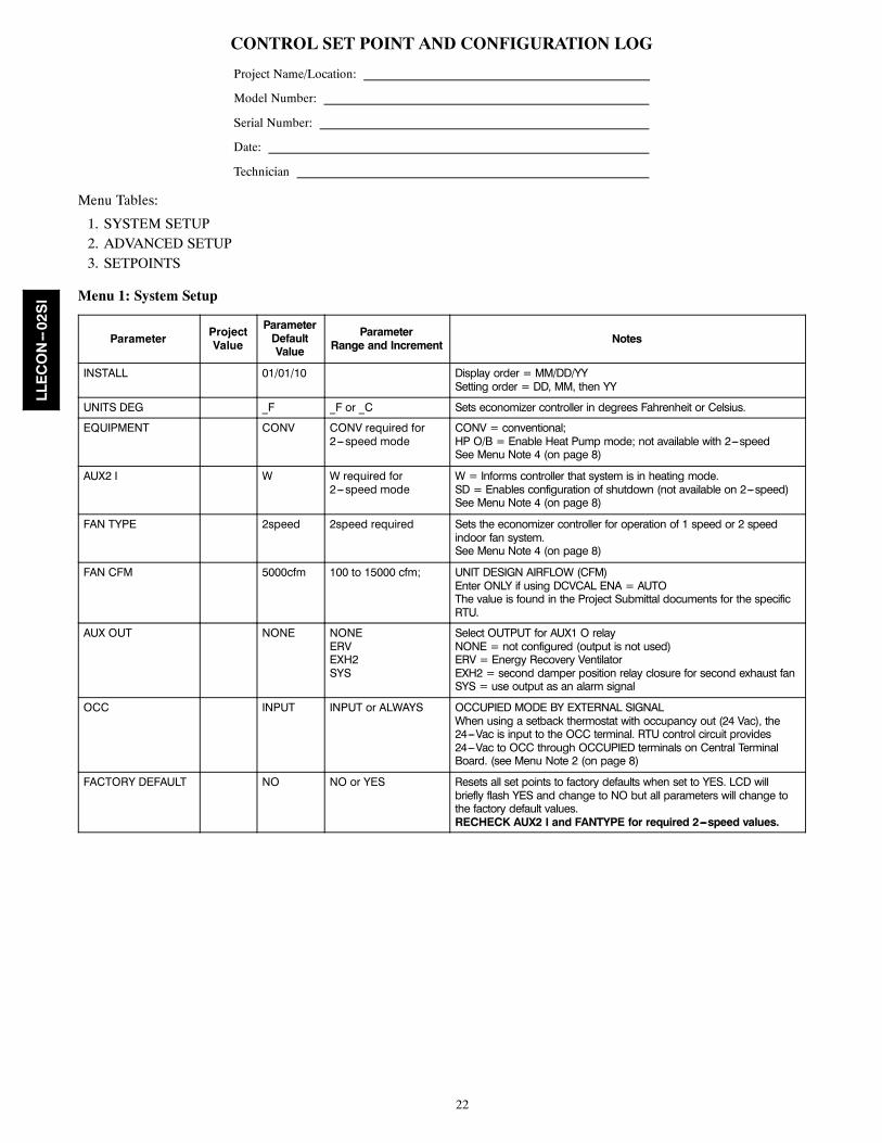
CONTROL SET POINT AND CONFIGURATION LOG
Project Name/Location:
Model Number:
Serial Number:
Date:
Technician
Menu Tables:
1. SYSTEM SETUP2. ADVANCED SETUP3. SETPOINTS
Menu 1: System Setup
Parameter ProjectValue
ParameterDefaultValue
ParameterRange and Increment Notes
INSTALL 01/01/10 Display order = MM/DD/YYSetting order = DD, MM, then YY
UNITS DEG _F _F or _C Sets economizer controller in degrees Fahrenheit or Celsius.
EQUIPMENT CONV CONV required for2---speed mode
CONV = conventional;HP O/B = Enable Heat Pump mode; not available with 2---speedSee Menu Note 4 (on page 8)
AUX2 I W W required for2---speed mode
W = Informs controller that system is in heating mode.SD = Enables configuration of shutdown (not available on 2---speed)See Menu Note 4 (on page 8)
FAN TYPE 2speed 2speed required Sets the economizer controller for operation of 1 speed or 2 speedindoor fan system.See Menu Note 4 (on page 8)
FAN CFM 5000cfm 100 to 15000 cfm; UNIT DESIGN AIRFLOW (CFM)Enter ONLY if using DCVCAL ENA = AUTOThe value is found in the Project Submittal documents for the specificRTU.
AUX OUT NONE NONEERVEXH2SYS
Select OUTPUT for AUX1 O relayNONE = not configured (output is not used)ERV = Energy Recovery VentilatorEXH2 = second damper position relay closure for second exhaust fanSYS = use output as an alarm signal
OCC INPUT INPUT or ALWAYS OCCUPIED MODE BY EXTERNAL SIGNALWhen using a setback thermostat with occupancy out (24 Vac), the24---Vac is input to the OCC terminal. RTU control circuit provides24---Vac to OCC through OCCUPIED terminals on Central TerminalBoard. (see Menu Note 2 (on page 8)
FACTORY DEFAULT NO NO or YES Resets all set points to factory defaults when set to YES. LCD willbriefly flash YES and change to NO but all parameters will change tothe factory default values.RECHECK AUX2 I and FANTYPE for required 2---speed values.
LLECON--02SI
23
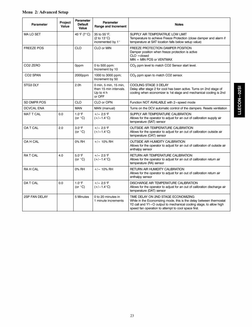
Menu 2: Advanced Setup
Parameter ProjectValue
ParameterDefaultValue
ParameterRange and Increment Notes
MA LO SET 45_F (7_C) 35 to 55_F;(2 to 13_C)incremented by 1_
SUPPLY AIR TEMPERATRUE LOW LIMITTemperature to achieve Freeze Protection (close damper and alarm iftemperature at SAT location falls below setup value)
FREEZE POS CLO CLO or MIN FREEZE PROTECTION DAMPER POSITIONDamper position when freeze protection is activeCLO =closedMIN = MIN POS or VENTMAX
CO2 ZERO 0ppm 0 to 500 ppm:Increment by 10
CO2 ppm level to match CO2 Sensor start level.
CO2 SPAN 2000ppm 1000 to 3000 ppm;Increment by 50
CO2 ppm span to match CO2 sensor.
STG3 DLY 2.0h 0 min, 5 min, 15 min,then 15 min intervals.Up to 4 hor OFF
COOLING STAGE 3 DELAYDelay after stage 2 for cool has been active. Turns on 2nd stage ofcooling when economizer is 1st stage and mechanical cooling is 2nd
SD DMPR POS CLO CLO or OPN Function NOT AVAILABLE with 2---speed mode
DCVCAL ENA MAN MAN (manual) Turns on the DCV automatic control of the dampers. Resets ventilation
MAT T CAL 0.0 1.0_F(or _C)
+/--- 2.5_F(+/---1.4_C)
SUPPLY AIR TEMPERATURE CALIBRATIONAllows for the operator to adjust for an out of calibration supply airtemperature (SAT) sensor
OA T CAL 2.0 3.0_F(or _C)
+/--- 2.5_F(+/---1.4_C)
OUTSIDE AIR TEMPERATURE CALIBRATIONAllows for the operator to adjust for an out of calibration outside airtemperature (OAT) sensor
OA H CAL 0% RH +/--- 10% RH OUTSIDE AIR HUMIDITY CALIBRATIONAllows for the operator to adjust for an out of calibration of outside airenthalpy sensor
RA T CAL 4.0 5.0_F(or _C)
+/--- 2.5_F(+/---1.4_C)
RETURN AIR TEMPERATURE CALIBRATIONAllows for the operator to adjust for an out of calibration return airtemperature (RA) sensor
RA H CAL 0% RH +/--- 10% RH RETURN AIR HUMIDITY CALIBRATIONAllows for the operator to adjust for an out of calibration return airenthalpy sensor
DA T CAL 0.0 1.0_F(or _C)
+/--- 2.5_F(+/---1.4_C)
DISCHARGE AIR TEMPERATURE CALIBRATIONAllows for the operator to adjust for an out of calibration discharge airtemperature (DAT) sensor
2SP FAN DELAY 5 Minutes 0 to 20 minutes in1 minute increments
TIME DELAY ON 2ND STAGE ECONOMIZINGWhile in the Economizing mode, this is the delay between thermostatY2 call and Y1---O output to mechanical cooling stage, to allow highspeed fan operation to attempt to cool space first.
LLECON--02SI
24
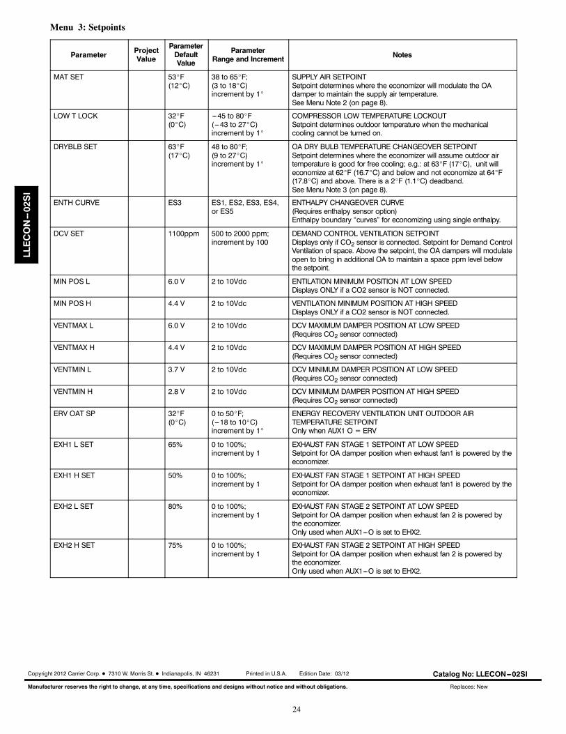
Menu 3: Setpoints
Parameter ProjectValue
ParameterDefaultValue
ParameterRange and Increment Notes
MAT SET 53_F(12_C)
38 to 65_F;(3 to 18_C)increment by 1_
SUPPLY AIR SETPOINTSetpoint determines where the economizer will modulate the OAdamper to maintain the supply air temperature.See Menu Note 2 (on page 8).
LOW T LOCK 32_F(0_C)
---45 to 80_F(---43 to 27_C)increment by 1_
COMPRESSOR LOW TEMPERATURE LOCKOUTSetpoint determines outdoor temperature when the mechanicalcooling cannot be turned on.
DRYBLB SET 63_F(17_C)
48 to 80_F;(9 to 27_C)increment by 1_
OA DRY BULB TEMPERATURE CHANGEOVER SETPOINTSetpoint determines where the economizer will assume outdoor airtemperature is good for free cooling; e.g.: at 63_F (17_C), unit willeconomize at 62_F (16.7_C) and below and not economize at 64_F(17.8_C) and above. There is a 2_F (1.1_C) deadband.See Menu Note 3 (on page 8).
ENTH CURVE ES3 ES1, ES2, ES3, ES4,or ES5
ENTHALPY CHANGEOVER CURVE(Requires enthalpy sensor option)Enthalpy boundary “curves” for economizing using single enthalpy.
DCV SET 1100ppm 500 to 2000 ppm;increment by 100
DEMAND CONTROL VENTILATION SETPOINTDisplays only if CO2 sensor is connected. Setpoint for Demand ControlVentilation of space. Above the setpoint, the OA dampers will modulateopen to bring in additional OA to maintain a space ppm level belowthe setpoint.
MIN POS L 6.0 V 2 to 10Vdc ENTILATION MINIMUM POSITION AT LOW SPEEDDisplays ONLY if a CO2 sensor is NOT connected.
MIN POS H 4.4 V 2 to 10Vdc VENTILATION MINIMUM POSITION AT HIGH SPEEDDisplays ONLY if a CO2 sensor is NOT connected.
VENTMAX L 6.0 V 2 to 10Vdc DCV MAXIMUM DAMPER POSITION AT LOW SPEED(Requires CO2 sensor connected)
VENTMAX H 4.4 V 2 to 10Vdc DCV MAXIMUM DAMPER POSITION AT HIGH SPEED(Requires CO2 sensor connected)
VENTMIN L 3.7 V 2 to 10Vdc DCV MINIMUM DAMPER POSITION AT LOW SPEED(Requires CO2 sensor connected)
VENTMIN H 2.8 V 2 to 10Vdc DCV MINIMUM DAMPER POSITION AT HIGH SPEED(Requires CO2 sensor connected)
ERV OAT SP 32_F(0_C)
0 to 50_F;(---18 to 10_C)increment by 1_
ENERGY RECOVERY VENTILATION UNIT OUTDOOR AIRTEMPERATURE SETPOINTOnly when AUX1 O = ERV
EXH1 L SET 65% 0 to 100%;increment by 1
EXHAUST FAN STAGE 1 SETPOINT AT LOW SPEEDSetpoint for OA damper position when exhaust fan1 is powered by theeconomizer.
EXH1 H SET 50% 0 to 100%;increment by 1
EXHAUST FAN STAGE 1 SETPOINT AT HIGH SPEEDSetpoint for OA damper position when exhaust fan1 is powered by theeconomizer.
EXH2 L SET 80% 0 to 100%;increment by 1
EXHAUST FAN STAGE 2 SETPOINT AT LOW SPEEDSetpoint for OA damper position when exhaust fan 2 is powered bythe economizer.Only used when AUX1---O is set to EHX2.
EXH2 H SET 75% 0 to 100%;increment by 1
EXHAUST FAN STAGE 2 SETPOINT AT HIGH SPEEDSetpoint for OA damper position when exhaust fan 2 is powered bythe economizer.Only used when AUX1---O is set to EHX2.
Copyright 2012 Carrier Corp. D 7310 W. Morris St. D Indianapolis, IN 46231 Printed in U.S.A. Edition Date: 03/12
Manufacturer reserves the right to change, at any time, specifications and designs without notice and without obligations.
Catalog No: LLECON---02SI
Replaces: New
LLECON--02SI