Embed Size (px)
Citation preview
Installation / User Manual
Rev 1.5
© All Rights Reserved
APsystems ECU-C Energy communication unitwith advanced functions
ECU-C Installation/User Manual 1
Table of Contents
Important Safety Instructions...................................................................................21.Introduction............................................................................................................32.Interface Explanation............................................................................................. 4
2.1 Interface Layout......................................................................................................... 42.2 AC Input Port..............................................................................................................42.3 DC Input Port..............................................................................................................42.4 RJ45 Ethernet Network Port...................................................................................... 52.5 RJ45 Signal(Only for Australia)............................................................................. 52.6 USB Interface............................................................................................................. 52.7 Reset.......................................................................................................................... 52.8 LED............................................................................................................................. 5
3.Hardware Installation.............................................................................................63.1 Preparation................................................................................................................ 63.2 Selecting an Installation Location for the ECU-C........................................................63.3 Cable Connections..................................................................................................... 83.4 RJ45 Signal connection.............................................................................................. 83.5 Internet Connection...................................................................................................83.6 Current transformer interface................................................................................. 103.7 Contactor connection.............................................................................................. 11
4.Basic Operation.................................................................................................... 124.1 Restore the factory set operation............................................................................12
5.Local Network Interface.......................................................................................135.1 Connecting to the ECU-C via the Local Wireless......................................................135.2 Home Screen............................................................................................................135.3 Real-time Data Screen..............................................................................................15
6.Remote ECU-C Management (EMA).................................................................... 256.1 ECU-C Configuration/ECU-C Status Page.................................................................266.2 Setting the ECU-C Time Zone...................................................................................276.3 Managing Inverter IDs and Updating the Inverter ID List........................................27
7.Technical Data...................................................................................................... 29

ECU-C Installation/User Manual 2
Important Safety Instructions
Symbols replace words on the equipment, on a display, or inmanuals
Trademark.
Caution, risk of electric shock.
Equipment protected throughout by double insulation orreinforced insulation
CE mark is attached to the solar inverter to verify that the unitfollows the provisions of the European Low Voltage and EMCDirectives.
Qualifiedpersonnel
Person adequately advised or supervised by an electricallyskilled person to enable him or her to perceive risks and to avoidhazards which electricity can create. For the purpose of thesafety information of this manual, a "qualified person" issomeone who is familiar with requirements for safety,refrigeration system and EMC and is authorized to energize,ground, and tag equipment, systems, and circuits in accordancewith established safety procedures. The inverter and enduessystem may only be commissioned and operated by qualifiedpersonnel.
ECU-C Installation/User Manual 3
1.Introduction
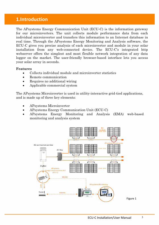
The APsystems Energy Communication Unit (ECU-C) is the information gatewayfor our microinverters. The unit collects module performance data from eachindividual microinverter and transfers this information to an Internet database inreal time. Through the APsystems Energy Monitoring and Analysis software, theECU-C gives you precise analysis of each microinverter and module in your solarinstallation from any web-connected device. The ECU-C’s integrated httpwebserver offers the simplest and most flexible network integration of any datalogger on the market. The user-friendly browser-based interface lets you accessyour solar array in seconds.
Features Collects individual module and microinverter statistics Remote communication Requires no additional wiring Applicable commercial system
The APsystems Microinverter is used in utility-interactive grid-tied applications,and is made up of three key elements:
APsystems Microinverter APsystems Energy Communication Unit (ECU-C) APsystems Energy Monitoring and Analysis (EMA) web-based
monitoring and analysis system
Figure 1
ECU-C Installation/User Manual 4
2.Interface Explanation
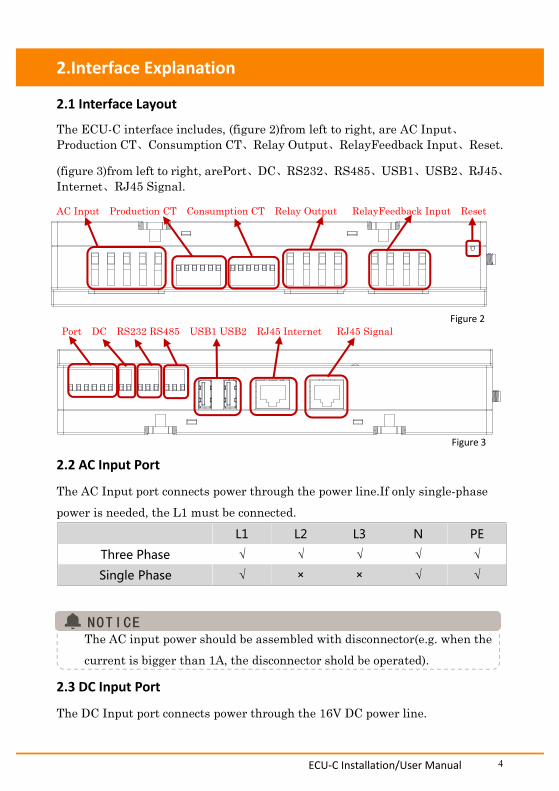
2.1 Interface Layout
The ECU-C interface includes, (figure 2)from left to right, are AC Input、Production CT、Consumption CT、Relay Output、RelayFeedback Input、Reset.
(figure 3)from left to right, arePort、DC、RS232、RS485、USB1、USB2、RJ45、Internet、RJ45 Signal.
AC Input Production CT Consumption CT Relay Output RelayFeedback Input Reset
Figure 2Port DC RS232 RS485 USB1 USB2 RJ45 Internet RJ45 Signal
Figure 3
2.2 AC Input Port
The AC Input port connects power through the power line.If only single-phasepower is needed, the L1 must be connected.
L1 L2 L3 N PE
Three Phase √ √ √ √ √
Single Phase √ × × √ √
The AC input power should be assembled with disconnector(e.g. when thecurrent is bigger than 1A, the disconnector shold be operated).
2.3 DC Input Port
The DC Input port connects power through the 16V DC power line.
ECU-C Installation/User Manual 5
2.Interface Explanation
2.4 RJ45 Ethernet Network PortThe ECU-C allows the user to communicate with the EMA, or log in to theECU-C's local page in the absence of the wired LAN and WLAN, to set up thesystem and view the system data via Ethernet network port.
Ethernet cable connection is recommended for stable communication.
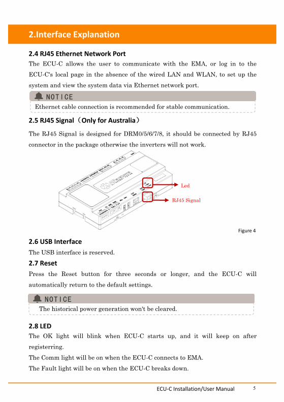
2.5 RJ45 Signal(Only for Australia)
The RJ45 Signal is designed for DRM0/5/6/7/8, it should be connected by RJ45connector in the package otherwise the inverters will not work.
Figure 4
2.6 USB InterfaceThe USB interface is reserved.2.7 ResetPress the Reset button for three seconds or longer, and the ECU-C willautomatically return to the default settings.
The historical power generation won't be cleared.
2.8 LEDThe OK light will blink when ECU-C starts up, and it will keep on afterregisterring.The Comm light will be on when the ECU-C connects to EMA.The Fault light will be on when the ECU-C breaks down.
RJ45 Signal
Led
ECU-C Installation/User Manual 6
3.Hardware Installation
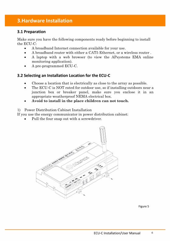
3.1 Preparation
Make sure you have the following components ready before beginning to installthe ECU-C:
A broadband Internet connection available for your use. A broadband router with either a CAT5 Ethernet, or a wireless router . A laptop with a web browser (to view the APsystems EMA online
monitoring application). A pre-programmed ECU-C.
3.2 Selecting an Installation Location for the ECU-C
Choose a location that is electrically as close to the array as possible. The ECU-C is NOT rated for outdoor use, so if installing outdoors near a
junction box or breaker panel, make sure you enclose it in anappropriate weatherproof NEMA electrical box.
Avoid to install in the place children can not touch.
1) Power Distribution Cabinet InstallationIf you use the energy communicator in power distribution cabinet:
Pull the four snap out with a screwdriver.
Figure 5

ECU-C Installation/User Manual 7
3.Hardware Instrallation
Attach two buckles below in the edge of the guide, press two bucklesabove, then embed to the edge of the guide.
Figure 6
Do not put the antennas inside a metal box, that will block the signal.
2) Using a Wall MountWhen mounting the ECU-C to a wall, make sure to select a cool, dry indoorlocation. According to the size of an icon, The energy communicator is fixed on the
wall with two Wall screws or wall anchors. Four M4 screws + spacers are fixed to the wall, and the punch sizes are
as follows:
Figure 7
110mm(4.3' )'
129.4mm(5' )'
ECU-C Installation/User Manual 8
3.Hardware Installation
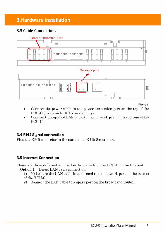
3.3 Cable Connections
Power Connection Port
Network port
Figure 8 Connect the power cable to the power connection port on the top of the
ECU-C.(Can also be DC power supply). Connect the supplied LAN cable to the network port on the bottom of the
ECU-C.
3.4 RJ45 Signal connectionPlug the RJ45 connector in the package to RJ45 Signal port.
3.5 Internet Connection
There are three different approaches to connecting the ECU-C to the Internet:Option 1: Direct LAN cable connection.1) Make sure the LAN cable is connected to the network port on the bottomof the ECU-C.2) Connect the LAN cable to a spare port on the broadband router.
ECU-C Installation/User Manual 9
3.Hardware Installation
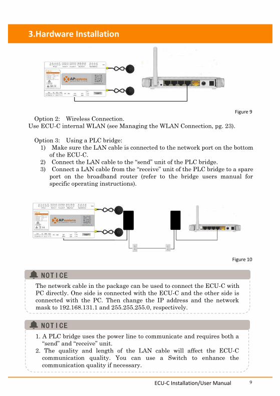
Figure 9Option 2: Wireless Connection.
Use ECU-C internal WLAN (see Managing the WLAN Connection, pg. 23).
Option 3: Using a PLC bridge:1) Make sure the LAN cable is connected to the network port on the bottom
of the ECU-C.2) Connect the LAN cable to the “send” unit of the PLC bridge.3) Connect a LAN cable from the “receive” unit of the PLC bridge to a spare
port on the broadband router (refer to the bridge users manual forspecific operating instructions).
Figure 10
The network cable in the package can be used to connect the ECU-C withPC directly. One side is connected with the ECU-C and the other side isconnected with the PC. Then change the IP address and the networkmask to 192.168.131.1 and 255.255.255.0, respectively.
1. A PLC bridge uses the power line to communicate and requires both a“send” and “receive” unit.
2. The quality and length of the LAN cable will affect the ECU-Ccommunication quality. You can use a Switch to enhance thecommunication quality if necessary.
ECU-C Installation/User Manual 10
3.Hardware Installation
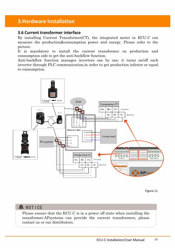
3.6 Current transformer interfaceBy installing Current Transformer(CT), the integrated meter in ECU-C canmeasure the production&consumption power and energy. Please refer to thepicture.It is mandatory to install the current transformer on production andconsumption side to get the anti-backflow function.Anti-backflow function manages inverters one by one: it turns on/off eachinverter through PLC communication,in order to get production inferior or equalto consumption.
Figure 11
Please ensure that the ECU-C is in a power off state when installing thetransformer.APsystems can provide the current transformers, pleasecontact us or our distributors.
ECU-C Installation/User Manual 11
3.Hardware Installation
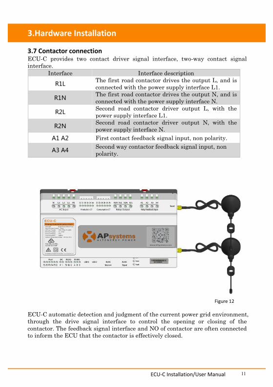
3.7 Contactor connectionECU-C provides two contact driver signal interface, two-way contact signalinterface.
Interface Interface descriptionR1L The first road contactor drives the output L, and is
connected with the power supply interface L1.R1N The first road contactor drives the output N, and is
connected with the power supply interface N.R2L Second road contactor driver output L, with the
power supply interface L1.R2N Second road contactor driver output N, with the
power supply interface N.A1 A2 First contact feedback signal input, non polarity.
A3 A4 Second way contactor feedback signal input, nonpolarity.
Figure 12
ECU-C automatic detection and judgment of the current power grid environment,through the drive signal interface to control the opening or closing of thecontactor. The feedback signal interface and NO of contactor are often connectedto inform the ECU that the contactor is effectively closed.
ECU-C Installation/User Manual 12
4.Basic Operation
4.1 Restore the factory set operation
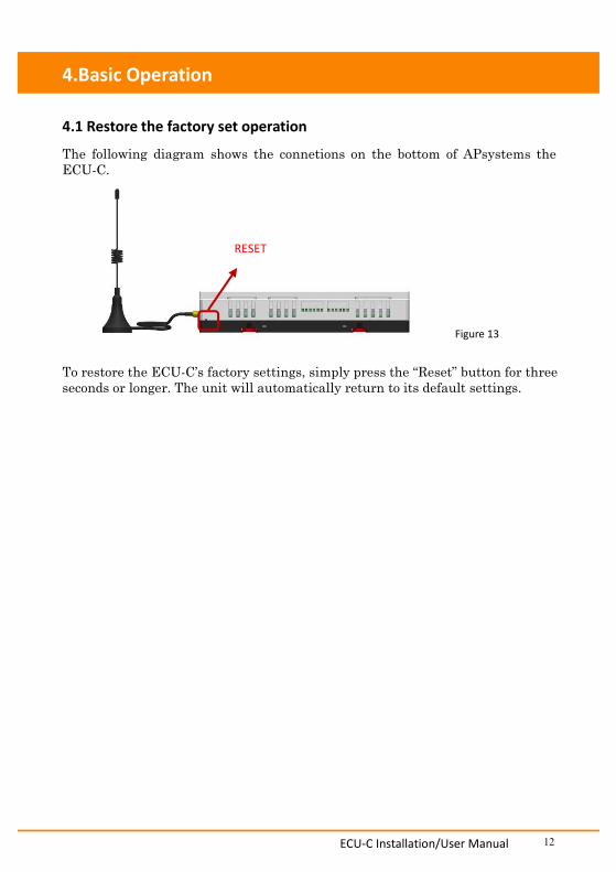
The following diagram shows the connetions on the bottom of APsystems theECU-C.
Figure 13
To restore the ECU-C’s factory settings, simply press the “Reset” button for threeseconds or longer. The unit will automatically return to its default settings.
RESET
ECU-C Installation/User Manual 13
5.Local Network Interface
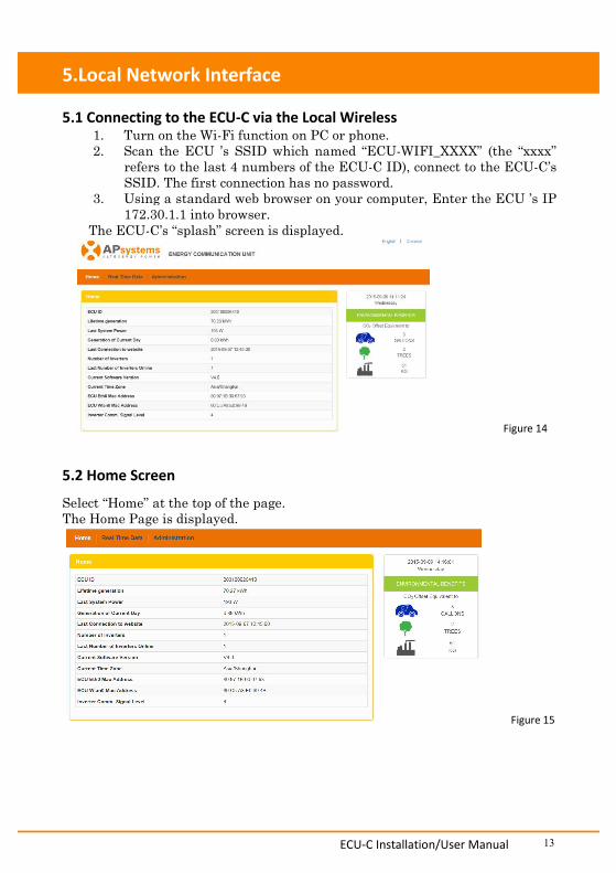
5.1 Connecting to the ECU-C via the Local Wireless1. Turn on the Wi-Fi function on PC or phone.2. Scan the ECU ’s SSID which named “ECU-WIFI_XXXX” (the “xxxx”
refers to the last 4 numbers of the ECU-C ID), connect to the ECU-C’sSSID. The first connection has no password.
3. Using a standard web browser on your computer, Enter the ECU ’s IP172.30.1.1 into browser.
The ECU-C’s “splash” screen is displayed.
Figure 14
5.2 Home Screen
Select “Home” at the top of the page.The Home Page is displayed.
Figure 15
ECU-C Installation/User Manual 14
5.Local Network Interface
ECU-C ID:
Lifetime Generation:
Last System Power:
Generation ofCurrent Day:
Last connection toWebsite:
This is a unique number that identifies this specificECU-C.Amount of power this system has generated during itslifetime.Amount of power the system was generating during itslast polling cycle.
Amount of power that has been generated during themost current day.
The last time the ECU-C checked into the centralAPsystems EMA database.
Number of Inverters:
Last Number ofInverters Online:
Current SoftwareVersion:Current Timezone:
ECU-C Eth0 MacAddressECU-C Wlan0 MacAddressInverter Comm.Signal Level
Number of inverters that have programmed into theECU-C.
Number of inverters that are checking in with theECU-C.
Current version of the firmware.Time zone that hasbeen programmed into the ECU-C.
Address of ECU-C’s LAN.
Address of the ECU-C’s internal WLAN.
The communication strength between inverters andECU-C. The range is 1-5, the higher the better.
ECU-C Installation/User Manual 15
5.Local Network Interface
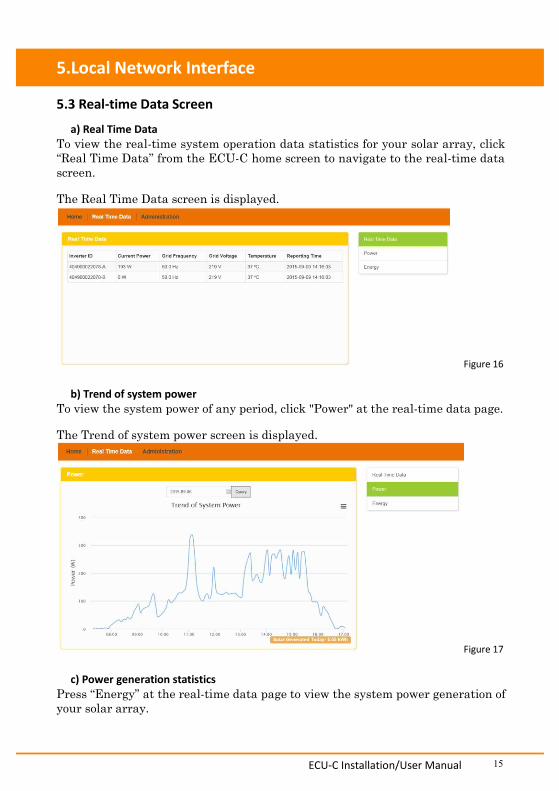
5.3 Real-time Data Screen
a) Real Time DataTo view the real-time system operation data statistics for your solar array, click“Real Time Data” from the ECU-C home screen to navigate to the real-time datascreen.
The Real Time Data screen is displayed.
Figure 16
b) Trend of system powerTo view the system power of any period, click "Power" at the real-time data page.
The Trend of system power screen is displayed.
Figure 17
c) Power generation statisticsPress “Energy” at the real-time data page to view the system power generation ofyour solar array.
ECU-C Installation/User Manual 16
5.Local Network Interface
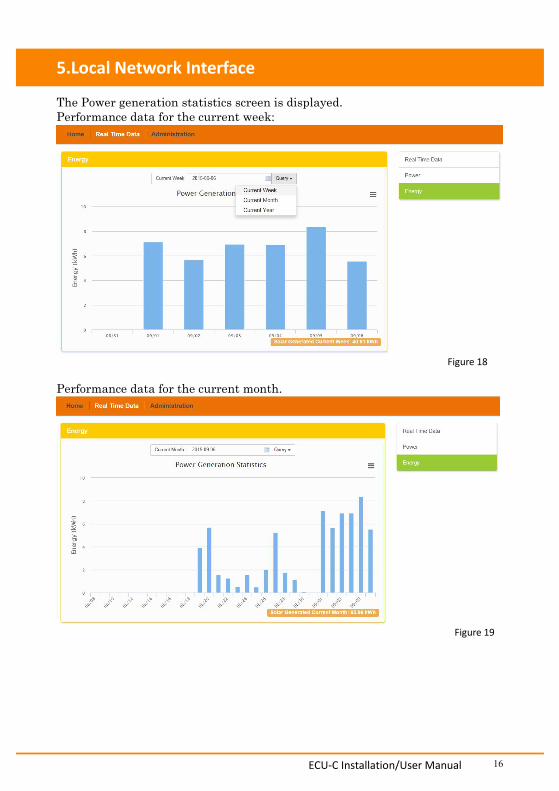
The Power generation statistics screen is displayed.Performance data for the current week:
Figure 18
Performance data for the current month.
Figure 19
ECU-C Installation/User Manual 17
5.Local Network Interface
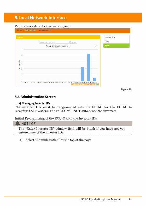
Performance data for the current year.
Figure 20
5.4 Administration Screen
a) Managing Inverter IDsThe inverter IDs must be programmed into the ECU-C for the ECU-C torecognize the inverters. The ECU-C will NOT auto-sense the inverters.
Initial Programming of the ECU-C with the Inverter IDs.
The “Enter Inverter ID” window field will be blank if you have not yetentered any of the inverter IDs.
1) Select “Administration” at the top of the page.
ECU-C Installation/User Manual 18
5.Local Network Interface
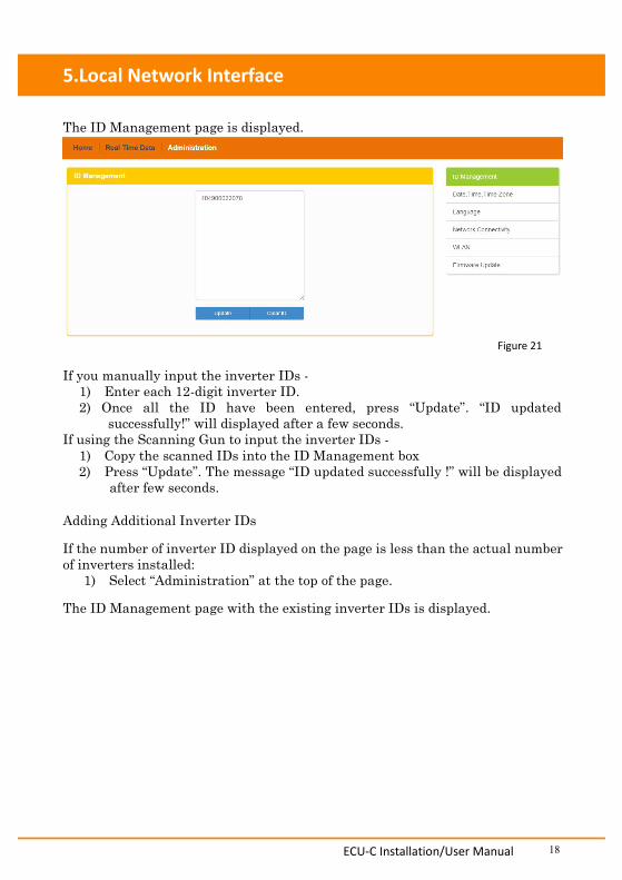
The ID Management page is displayed.
Figure 21
If you manually input the inverter IDs -1) Enter each 12-digit inverter ID.2) Once all the ID have been entered, press “Update”. “ID updated
successfully!” will displayed after a few seconds.If using the Scanning Gun to input the inverter IDs -
1) Copy the scanned IDs into the ID Management box2) Press “Update”. The message “ID updated successfully !” will be displayed
after few seconds.
Adding Additional Inverter IDs
If the number of inverter ID displayed on the page is less than the actual numberof inverters installed:
1) Select “Administration” at the top of the page.
The ID Management page with the existing inverter IDs is displayed.
ECU-C Installation/User Manual 19
5.Local Network Interface
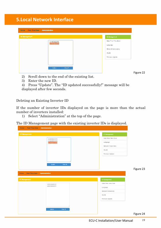
Figure 222) Scroll down to the end of the existing list.3) Enter the new ID.4) Press “Update”. The “ID updated successfully!” message will bedisplayed after few seconds.
Deleting an Existing Inverter ID
If the number of inverter IDs displayed on the page is more than the actualnumber of inverters installed:
1) Select “Administration” at the top of the page.
The ID Management page with the existing inverter IDs is displayed.
Figure 23
Figure 24
ECU-C Installation/User Manual 20
5.Local Network Interface
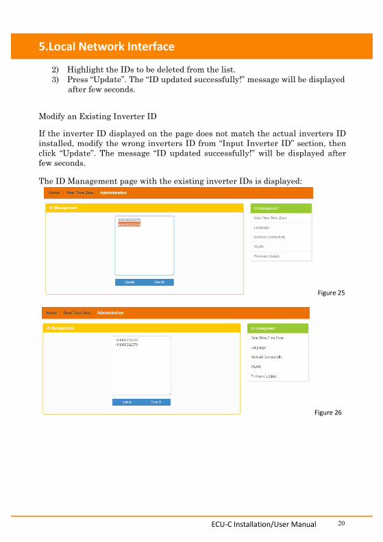
2) Highlight the IDs to be deleted from the list.3) Press “Update”. The “ID updated successfully!” message will be displayed
after few seconds.
Modify an Existing Inverter ID
If the inverter ID displayed on the page does not match the actual inverters IDinstalled, modify the wrong inverters ID from “Input Inverter ID” section, thenclick “Update”. The message “ID updated successfully!” will be displayed afterfew seconds.
The ID Management page with the existing inverter IDs is displayed:
Figure 25
Figure 26
ECU-C Installation/User Manual 21
5.Local Network Interface
Clearing inverter IDs
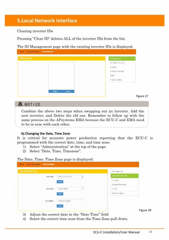
Pressing “Clear ID” deletes ALL of the inverter IDs from the list.
The ID Management page with the existing inverter IDs is displayed.
Figure 27
Combine the above two steps when swapping out an inverter. Add thenew inverter, and Delete the old one. Remember to follow up with thesame process on the APsystems EMA because the ECU-C and EMA needto be in sync with each other.
b) Changing the Date, Time ZoneIt is critical for accurate power production reporting that the ECU-C isprogrammed with the correct date, time, and time zone.
1) Select “Administration” at the top of the page.2) Select “Date, Time, Timezone”.
The Date, Time, Time Zone page is displayed:
Figure 283) Adjust the correct date in the “Date Time” field4) Select the correct time zone from the Time Zone pull down.
ECU-C Installation/User Manual 22
5.Local Network Interface
You can skip step 3 by selecting the correct time zone.Selecting the correct time zone automatically updates both the date andcurrent time.
c) Changing the LanguageUsers can switch language between English and Chinese.
1) Select “Administration” at the top of the page.2) Select “Language”.
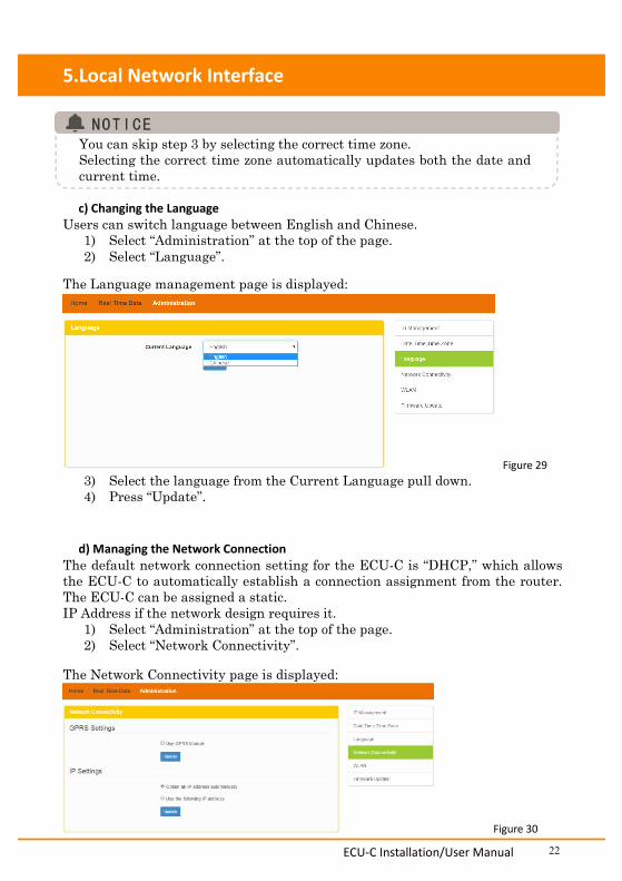
The Language management page is displayed:
Figure 293) Select the language from the Current Language pull down.4) Press “Update”.
d) Managing the Network ConnectionThe default network connection setting for the ECU-C is “DHCP,” which allowsthe ECU-C to automatically establish a connection assignment from the router.The ECU-C can be assigned a static.IP Address if the network design requires it.
1) Select “Administration” at the top of the page.2) Select “Network Connectivity”.
The Network Connectivity page is displayed:
Figure 30
ECU-C Installation/User Manual 23
5.Local Network Interface
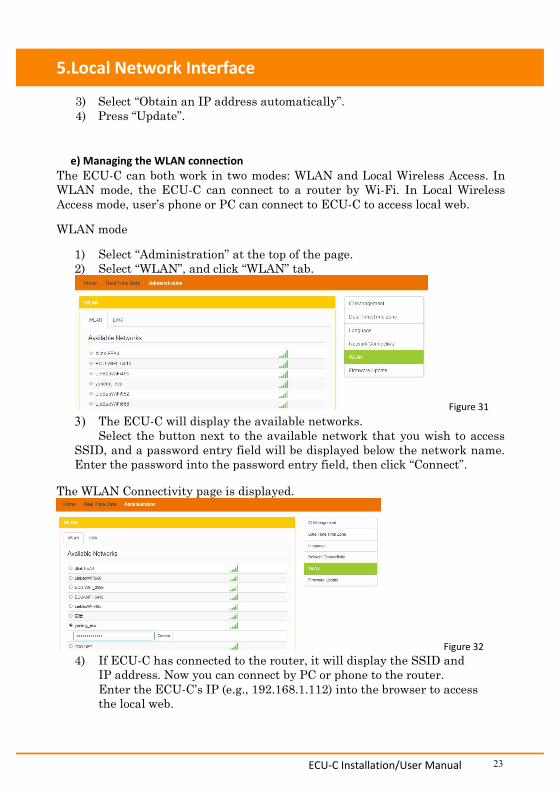
3) Select “Obtain an IP address automatically”.4) Press “Update”.
e) Managing the WLAN connectionThe ECU-C can both work in two modes: WLAN and Local Wireless Access. InWLAN mode, the ECU-C can connect to a router by Wi-Fi. In Local WirelessAccess mode, user’s phone or PC can connect to ECU-C to access local web.
WLAN mode
1) Select “Administration” at the top of the page.2) Select “WLAN”, and click “WLAN” tab.
Figure 313) The ECU-C will display the available networks.
Select the button next to the available network that you wish to accessSSID, and a password entry field will be displayed below the network name.Enter the password into the password entry field, then click “Connect”.
The WLAN Connectivity page is displayed.
Figure 324) If ECU-C has connected to the router, it will display the SSID and
IP address. Now you can connect by PC or phone to the router.Enter the ECU-C’s IP (e.g., 192.168.1.112) into the browser to accessthe local web.
ECU-C Installation/User Manual 24
5.Local Network Interface
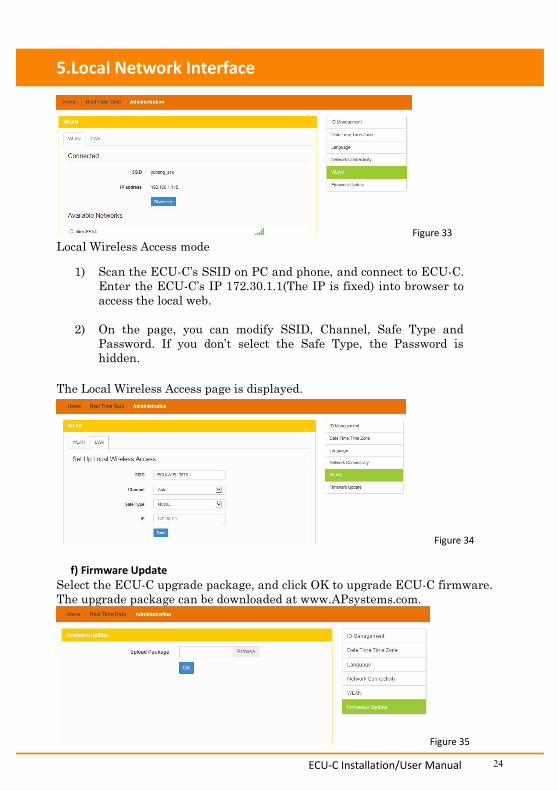
Figure 33Local Wireless Access mode
1) Scan the ECU-C’s SSID on PC and phone, and connect to ECU-C.Enter the ECU-C’s IP 172.30.1.1(The IP is fixed) into browser toaccess the local web.
2) On the page, you can modify SSID, Channel, Safe Type andPassword. If you don’t select the Safe Type, the Password ishidden.
The Local Wireless Access page is displayed.
Figure 34
f) Firmware UpdateSelect the ECU-C upgrade package, and click OK to upgrade ECU-C firmware.The upgrade package can be downloaded at www.APsystems.com.
Figure 35
ECU-C Installation/User Manual 25
6.Remote ECU-C Management (EMA)
The ECU-C has been designed with remote connect functionality. You can accessthis remote functionality through the APsystems Energy Monitoring & Analysis(EMA) website, using your installer login credentials. Changes made remotelythrough the EMA do not take effect until the ECU-C’s next reporting cycle.The ECU-C must first be installed with Internet connectivity.
The ECU-C remote functionality allows you to do the following: Set Time Zones Manage Inverter IDs
There are additional ECU-C functions available but the instructions are notoutlined in this document. If you need to access one of the following features,please contact APsystems Technical Support:
Change system parameters Turn the inverters ON and OFF Reset GFDI Reset Power Settings
This section of the documentation assumes you have a workingknowledge of the APsystems EMA.
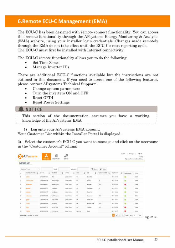
1) Log onto your APsystems EMA account.Your Customer List within the Installer Portal is displayed.
2) Select the customer’s ECU-C you want to manage and click on the usernamein the "Customer Account" column.
Figure 36
ECU-C Installation/User Manual 26
6.Remote ECU-C Management (EMA)
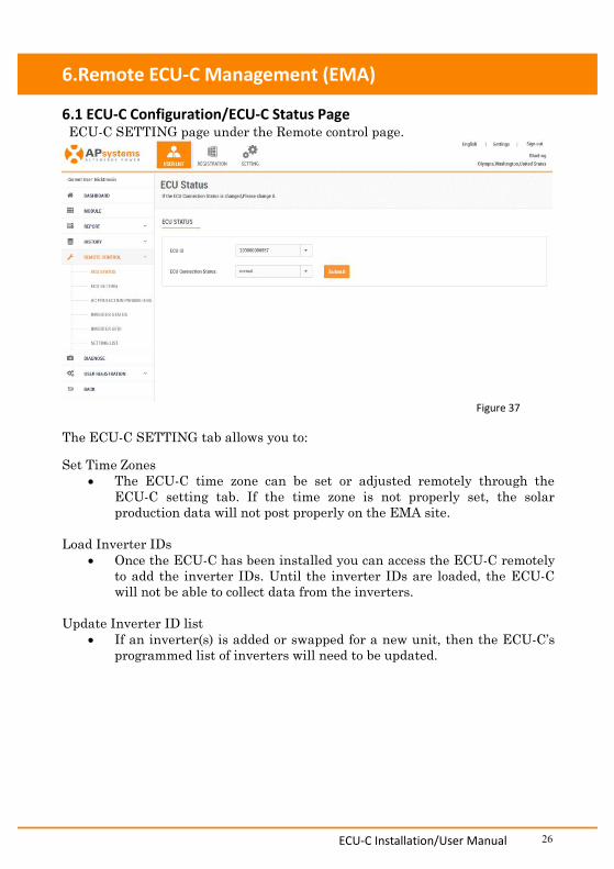
6.1 ECU-C Configuration/ECU-C Status PageECU-C SETTING page under the Remote control page.
Figure 37
The ECU-C SETTING tab allows you to:
Set Time Zones The ECU-C time zone can be set or adjusted remotely through the
ECU-C setting tab. If the time zone is not properly set, the solarproduction data will not post properly on the EMA site.
Load Inverter IDs Once the ECU-C has been installed you can access the ECU-C remotely
to add the inverter IDs. Until the inverter IDs are loaded, the ECU-Cwill not be able to collect data from the inverters.
Update Inverter ID list If an inverter(s) is added or swapped for a new unit, then the ECU-C’s
programmed list of inverters will need to be updated.
ECU-C Installation/User Manual 27
6.Remote ECU-C Management (EMA)
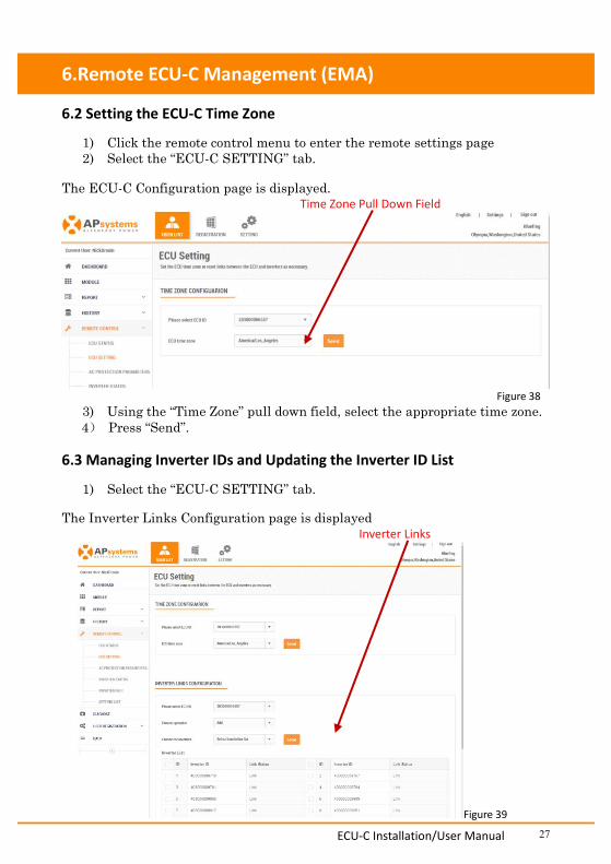
6.2 Setting the ECU-C Time Zone
1) Click the remote control menu to enter the remote settings page2) Select the “ECU-C SETTING” tab.
The ECU-C Configuration page is displayed.Time Zone Pull Down Field
Figure 383) Using the “Time Zone” pull down field, select the appropriate time zone.4) Press “Send”.
6.3 Managing Inverter IDs and Updating the Inverter ID List
1) Select the “ECU-C SETTING” tab.
The Inverter Links Configuration page is displayedInverter Links
Figure 39
ECU-C Installation/User Manual 28
6.Remote ECU-C Management (EMA)
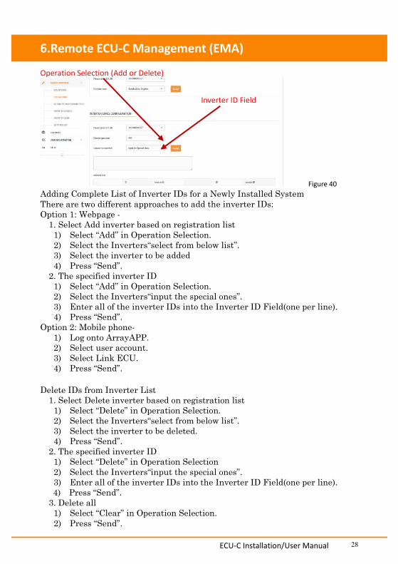
Operation Selection (Add or Delete)
Figure 40Adding Complete List of Inverter IDs for a Newly Installed SystemThere are two different approaches to add the inverter IDs:Option 1: Webpage -1. Select Add inverter based on registration list1) Select “Add” in Operation Selection.2) Select the Inverters“select from below list”.3) Select the inverter to be added4) Press “Send”.2. The specified inverter ID1) Select “Add” in Operation Selection.2) Select the Inverters“input the special ones”.3) Enter all of the inverter IDs into the Inverter ID Field(one per line).4) Press “Send”.
Option 2: Mobile phone-1) Log onto ArrayAPP.2) Select user account.3) Select Link ECU.4) Press “Send”.
Delete IDs from Inverter List1. Select Delete inverter based on registration list1) Select “Delete” in Operation Selection.2) Select the Inverters“select from below list”.3) Select the inverter to be deleted.4) Press “Send”.2. The specified inverter ID1) Select “Delete” in Operation Selection2) Select the Inverters“input the special ones”.3) Enter all of the inverter IDs into the Inverter ID Field(one per line).4) Press “Send”.3. Delete all1) Select “Clear” in Operation Selection.2) Press “Send”.
Inverter ID Field
ECU-C Installation/User Manual 29
7.Technical Data
Specifications subject to change without notice.Please ensure you are using the most recent update found at www.APsystems.com.
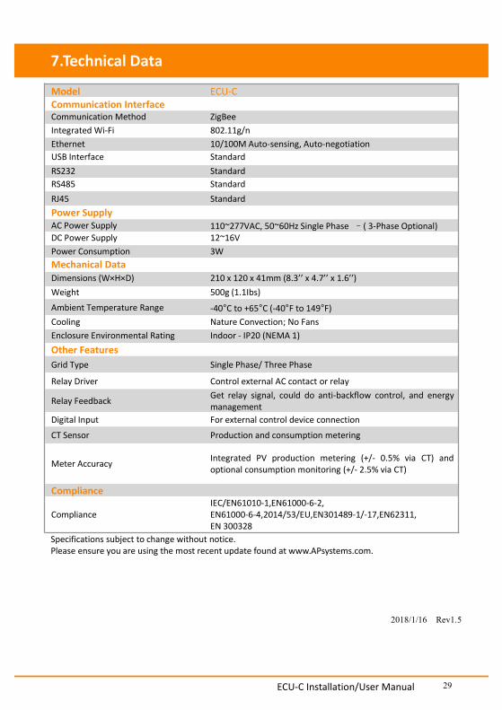
Model ECU-CCommunication InterfaceCommunication Method ZigBeeIntegrated Wi-Fi 802.11g/nEthernet 10/100M Auto-sensing, Auto-negotiationUSB Interface StandardRS232 StandardRS485 StandardRJ45 StandardPower SupplyAC Power Supply 110~277VAC, 50~60Hz Single Phase –( 3-Phase Optional)DC Power Supply 12~16VPower Consumption 3WMechanical DataDimensions (W×H×D) 210 x 120 x 41mm (8.3’’ x 4.7’’ x 1.6’’)Weight 500g (1.1Ibs)
Ambient Temperature Range -40°C to +65°C (-40°F to 149°F)Cooling Nature Convection; No FansEnclosure Environmental Rating Indoor - IP20 (NEMA 1)Other FeaturesGrid Type Single Phase/ Three Phase
Relay Driver Control external AC contact or relay
Relay Feedback Get relay signal, could do anti-backflow control, and energymanagement
Digital Input For external control device connection
CT Sensor Production and consumption metering
Meter Accuracy Integrated PV production metering (+/- 0.5% via CT) andoptional consumption monitoring (+/- 2.5% via CT)
Compliance
ComplianceIEC/EN61010-1,EN61000-6-2,EN61000-6-4,2014/53/EU,EN301489-1/-17,EN62311,EN 300328
2018/1/16 Rev1.5

ECU-C Installation/User Manual 30
Disposal of your old appliance
1. When this crossed-out wheeled bin symbol is attached to a product, itmeans the product is covered by the European Directive 2002/96/EC.
2. All electrical and electronic products should be disposed of separatelyfrom the municipal waste stream via designated collection facilitiesappointed by the government or the local authorities.
3. The correct disposal of your old appliance will help prevent potentialnegative consequences for the environment and human health.
4. For more detailed information about disposal of your old appliance,please contact your city office, waste disposal service or the shop whereyou purchased the product.

ECU-C Installation/User Manual 31
Contact Information
ALTENERGY POWER SYSTEM Inc.
www.APsystems.com
APsystems Jiaxing ChinaNo. 1, Yatai Road, Nanhu District, Jiaxing, ZhejiangTel: +86 573 8398 6967Mail: [email protected]
APsystems Shanghai ChinaB403 No. 188, Zhangyang Road, Pudong, ShanghaiTel: +86 021 3392 8205Mail: [email protected]
APsystems AustraliaSuite 502, 8 Help Street, Chatswood NSW 2067 AustraliaTel: +61 (0)2 8034 6587Mail: [email protected]
APsystems America600 Ericksen Ave NE, Suite 200 Seattle, WA 98110Tel: 844-666-7035Mail: [email protected]
APsystems EuropeRue des Monts dor ZAC de Folliouses Sud-Les Echets 01700 Miribel, FranceTel: +33-481 65 60 40Mail: [email protected]