Embed Size (px)
Citation preview
Installing Cisco TelePresence System Profile 42”/52”
Page 178-19778-01 Profile 42-52 Installation Sheet | December 2010 | © 2010 Cisco Systems, Inc. All rights reserved.
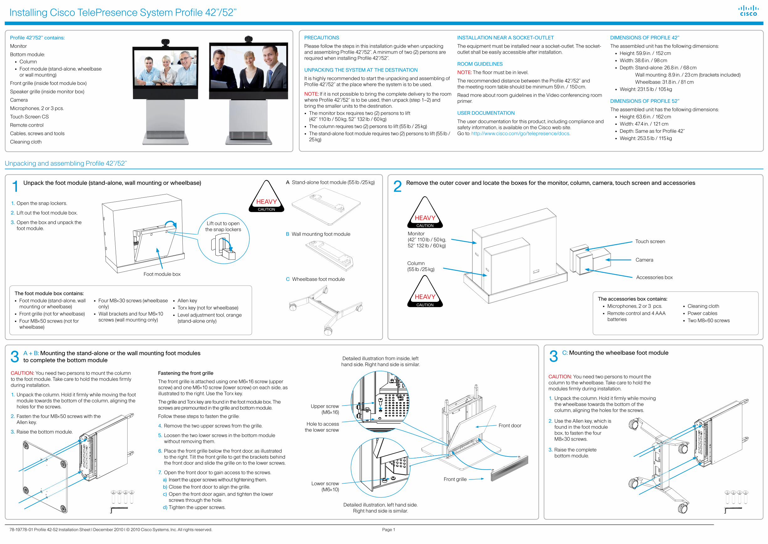
3 A + B: Mounting the stand-alone or the wall mounting foot modules to complete the bottom module
Rev. Date Prep. Checked Change
---
Telecom AS ---------
---------Part weight:
Sheet size:Scale:
Surface treatmentSpeci�cation: MaterialTolerances
Unit:
Europeanprojection
Sheet 1 of 1
All materials, �nishes, and proccessesmust comply with the RoHS directives
Dimensions without paint or �nish
Flame class requirement: -
ProcessesType:Manufacturer:Type number:Thickness:Color:Surface:Glossiness:Flame class:UL reference:3D CAD model �le 120800 rev. 03A+ is master
Column 42/52 w/steel frame120800 rev.
23617g
A3mm
1:4
---
Telecom AS ---------
---------Part weight:
Sheet size:Scale:
Surface treatmentSpeci�cation: MaterialTolerances
Unit:
Europeanprojection
Sheet 2 of 2
All materials, �nishes, and proccessesmust comply with the RoHS directives
Dimensions without paint or �nish
Flame class requirement: -
ProcessesType:Manufacturer:Type number:Thickness:Color:Surface:Glossiness:Flame class:UL reference:3D CAD model �le 117324 rev. 00E+ is master
TANDBERG Aquarius 52"117324 rev.00A+
53908g
A3mm
1:5
Rev. Date Prep. Checked Change
---
Telecom AS ---------
---------Part weight:
Sheet size:Scale:
Surface treatmentSpeci�cation: MaterialTolerances
Unit:
Europeanprojection
Sheet 1 of 1
All materials, �nishes, and proccessesmust comply with the RoHS directives
Dimensions without paint or �nish
Flame class requirement: -
ProcessesType:Manufacturer:Type number:Thickness:Color:Surface:Glossiness:Flame class:UL reference:3D CAD model �le 120800 rev. 03A+ is master
Column 42/52 w/steel frame120800 rev.
23617g
A3mm
1:4
1 Unpack the foot module (stand-alone, wall mounting or wheelbase)
Lift out to open the snap lockers
2 Remove the outer cover and locate the boxes for the monitor, column, camera, touch screen and accessories
C Wheelbase foot module
3 C: Mounting the wheelbase foot module
The accessories box contains:• Microphones, 2 or 3 pcs.• Remote control and 4 AAA
batteries
• Cleaning cloth• Power cables• Two M8×60 screws
PRECAUTIONS
Please follow the steps in this installation guide when unpacking and assembling Profile 42”/52”. A minimum of two (2) persons are required when installing Profile 42”/52”.
UNPACKING THE SYSTEM AT THE DESTINATION
It is highly recommended to start the unpacking and assembling of Profile 42”/52” at the place where the system is to be used.
NOTE: If it is not possible to bring the complete delivery to the room where Profile 42”/52” is to be used, then unpack (step 1–2) and bring the smaller units to the destination. • The monitor box requires two (2) persons to lift
(42” 110 lb / 50 kg, 52” 132 lb / 60 kg)• The column requires two (2) persons to lift (55 lb / 25 kg)• The stand-alone foot module requires two (2) persons to lift (55 lb /
25 kg)
INSTALLATION NEAR A SOCKET-OUTLET
The equipment must be installed near a socket-outlet. The socket-outlet shall be easily accessible after installation.
ROOM GUIDELINES
NOTE: The floor must be in level.
The recommended distance between the Profile 42”/52” and the meeting room table should be minimum 59 in. / 150 cm.
Read more about room guidelines in the Video conferencing room primer.
USER DOCUMENTATION
The user documentation for this product, including compliance and safety information, is available on the Cisco web site. Go to: http://www.cisco.com/go/telepresence/docs.
DIMENSIONS OF PROFILE 42”
The assembled unit has the following dimensions:• Height: 59.9 in. / 152 cm• Width: 38.6 in. / 98 cm• Depth: Stand-alone: 26.8 in. / 68 cm
Wall mounting: 8.9 in. / 23 cm (brackets included) Wheelbase: 31.8 in. / 81 cm
• Weight: 231.5 lb / 105 kg
DIMENSIONS OF PROFILE 52”
The assembled unit has the following dimensions:• Height: 63.6 in. / 162 cm• Width: 47.4 in. / 121 cm• Depth: Same as for Profile 42”• Weight: 253.5 lb / 115 kg
Profile 42”/52” contains:
Monitor
Bottom module:• Column• Foot module (stand-alone, wheelbase
or wall mounting)
Front grille (inside foot module box)
Speaker grille (inside monitor box)
Camera
Microphones, 2 or 3 pcs.
Touch Screen CS
Remote control
Cables, screws and tools
Cleaning cloth
1. Open the snap lockers.
2. Lift out the foot module box.
3. Open the box and unpack the foot module.
A Stand-alone foot module (55 lb /25 kg)
CAUTION: You need two persons to mount the column to the foot module. Take care to hold the modules firmly during installation.
1. Unpack the column. Hold it firmly while moving the foot module towards the bottom of the column, aligning the holes for the screws.
2. Fasten the four M8×50 screws with the Allen key.
3. Raise the bottom module.
CAUTION: You need two persons to mount the column to the wheelbase. Take care to hold the modules firmly during installation.
1. Unpack the column. Hold it firmly while moving the wheelbase towards the bottom of the column, aligning the holes for the screws.
2. Use the Allen key, which is found in the foot module box, to fasten the four M8×30 screws.
3. Raise the complete bottom module.
B Wall mounting foot module
Fastening the front grille
The front grille is attached using one M6×16 screw (upper screw) and one M6×10 screw (lower screw) on each side, as illustrated to the right. Use the Torx key.
The grille and Torx key are found in the foot module box. The screws are premounted in the grille and bottom module.
Follow these steps to fasten the grille:
4. Remove the two upper screws from the grille.
5. Loosen the two lower screws in the bottom module without removing them.
6. Place the front grille below the front door, as illustrated to the right. Tilt the front grille to get the brackets behind the front door and slide the grille on to the lower screws.
7. Open the front door to gain access to the screws. a) Insert the upper screws without tightening them. b) Close the front door to align the grille.c) Open the front door again, and tighten the lower
screws through the hole. d) Tighten the upper screws.
Hole to access the lower screw
Front door
Front grille
Upper screw (M6×16)
CAUTION
HEAVY
Camera
Accessories box
Touch screen
Monitor (42” 110 lb / 50 kg, 52” 132 lb / 60 kg)
Rev. Date Prep. Checked Change
---
Telecom AS ---------
--------Part weight:
Sheet size:Scale:
Surface treatmentSpecification: MaterialTolerances
Unit:
Europeanprojection
Sheet 1 of 1
All materials, finishes, and proccessesmust comply with the RoHS directives
Dimensions without paint or finish
Flame class requirement: -
ProcessesType:Manufacturer:Type number:Thickness:Color:Surface:Glossiness:Flame class:UL reference:3D CAD model file 121608 rev. 01 is master
121608 rev.
g
A3mm
1:7
Column (55 lb /25 kg)
The foot module box contains:• Foot module (stand-alone, wall
mounting or wheelbase)• Front grille (not for wheelbase)• Four M8×50 screws (not for
wheelbase)
• Four M8×30 screws (wheelbase only)
• Wall brackets and four M6×10 screws (wall mounting only)
• Allen key• Torx key (not for wheelbase)• Level adjustment tool, orange
(stand-alone only)
Foot module box
Rev. Date Prep. Checked Change
---
Telecom AS ---------
---------Part weight:
Sheet size:Scale:
Surface treatmentSpecification: MaterialTolerances
Unit:
Europeanprojection
Sheet 1 of 2
All materials, finishes, and proccessesmust comply with the RoHS directives
Dimensions without paint or finish
Flame class requirement: -
ProcessesType:Manufacturer:Type number:Thickness:Color:Surface:Glossiness:Flame class:UL reference:3D CAD model file 117324 rev. 00E+ is master
TANDBERG Aquarius 52"117324 rev.00A+
53908g
A3mm
1:7
Detailed illustration, left hand side. Right hand side is similar.
Lower screw (M6×10)
Detailed illustration from inside, left hand side. Right hand side is similar.
CAUTION
HEAVY
Unpacking and assembling Profile 42”/52”
CAUTION
HEAVY
Installing Cisco TelePresence System Profile 42”/52”
Page 278-19778-01 Profile 42-52 Installation Sheet | December 2010 | © 2010 Cisco Systems, Inc. All rights reserved.
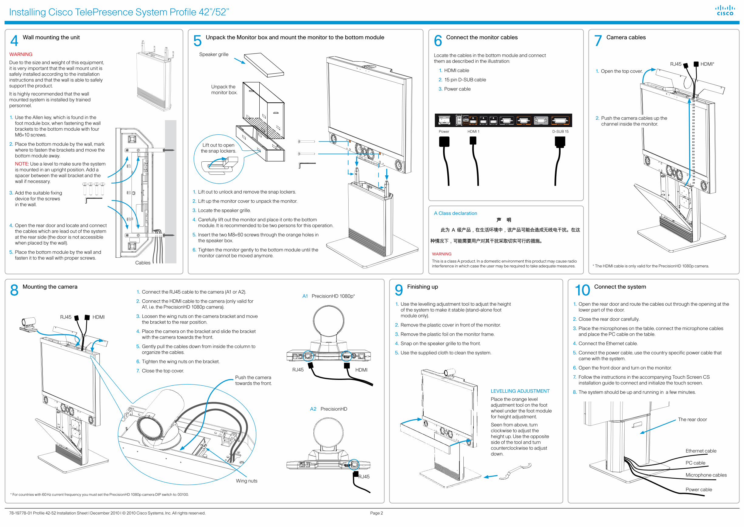
7 Camera cables
8 Mounting the camera 10 Connect the system9 Finishing up
4 Wall mounting the unit
Rev. Date Prep. Checked Change
---
Telecom AS ---------
---------Part weight:
Sheet size:Scale:
Surface treatmentSpecification: MaterialTolerances
Unit:
Europeanprojection
Sheet 1 of 1
All materials, finishes, and proccessesmust comply with the RoHS directives
Dimensions without paint or finish
Flame class requirement: -
ProcessesType:Manufacturer:Type number:Thickness:Color:Surface:Glossiness:Flame class:UL reference:3D CAD model file 117324 rev. 00E+ is master
TANDBERG Aquarius 52"117324 rev.
85203g
A3mm
1:20
5 Unpack the Monitor box and mount the monitor to the bottom module 6 Connect the monitor cables
1. Use the Allen key, which is found in the foot module box, when fastening the wall brackets to the bottom module with four M6×10 screws.
2. Place the bottom module by the wall, mark where to fasten the brackets and move the bottom module away.
NOTE: Use a level to make sure the system is mounted in an upright position. Add a spacer between the wall bracket and the wall if necessary.
3. Add the suitable fixing device for the screws in the wall.
4. Open the rear door and locate and connect the cables which are lead out of the system at the rear side (the door is not accessible when placed by the wall).
5. Place the bottom module by the wall and fasten it to the wall with proper screws.
1. Connect the RJ45 cable to the camera (A1 or A2).
2. Connect the HDMI cable to the camera (only valid for A1, i.e. the PrecisionHD 1080p camera).
3. Loosen the wing nuts on the camera bracket and move the bracket to the rear position.
4. Place the camera on the bracket and slide the bracket with the camera towards the front.
5. Gently pull the cables down from inside the column to organize the cables.
6. Tighten the wing nuts on the bracket.
7. Close the top cover.
2. Push the camera cables up the channel inside the monitor.
Ethernet cable
PC cable
Microphone cables
Power cable
HDMI*RJ45
HDMIRJ45
1. Open the top cover.
A1 PrecisionHD 1080p*
HDMIRJ45
EXTRACAMERA
12V DC INPOWER
HDVIDEO OUT
HDMI
HDVIDEO OUT
CODEC
KENSINGTONLOCK
A2 PrecisionHD
RJ45
* For countries with 60 Hz current frequency you must set the PrecisionHD 1080p camera DIP switch to: 00100.
1. Open the rear door and route the cables out through the opening at the lower part of the door.
2. Close the rear door carefully.
3. Place the microphones on the table, connect the microphone cables and place the PC cable on the table.
4. Connect the Ethernet cable.
5. Connect the power cable, use the country specific power cable that came with the system.
6. Open the front door and turn on the monitor.
7. Follow the instructions in the accompanying Touch Screen CS installation guide to connect and initialize the touch screen.
8. The system should be up and running in a few minutes.
1. Lift out to unlock and remove the snap lockers.
2. Lift up the monitor cover to unpack the monitor.
3. Locate the speaker grille.
4. Carefully lift out the monitor and place it onto the bottom module. It is recommended to be two persons for this operation.
5. Insert the two M8×60 screws through the orange holes in the speaker box.
6. Tighten the monitor gently to the bottom module until the monitor cannot be moved anymore.
Lift out to open the snap lockers.
1. Use the levelling adjustment tool to adjust the height of the system to make it stable (stand-alone foot module only).
2. Remove the plastic cover in front of the monitor.
3. Remove the plastic foil on the monitor frame.
4. Snap on the speaker grille to the front.
5. Use the supplied cloth to clean the system.
The rear door
LEVELLING ADJUSTMENT
Place the orange level adjustment tool on the foot wheel under the foot module for height adjustment.
Seen from above, turn clockwise to adjust the height up. Use the opposite side of the tool and turn counterclockwise to adjust down.
Unpack the monitor box.
Cables
WARNING
Due to the size and weight of this equipment, it is very important that the wall mount unit is safely installed according to the installation instructions and that the wall is able to safely support the product.
It is highly recommended that the wall mounted system is installed by trained personnel.
Wing nuts
Push the camera towards the front.
Speaker grille
* The HDMI cable is only valid for the PrecisionHD 1080p camera.
Locate the cables in the bottom module and connect them as described in the illustration:
1. HDMI cable
2. 15 pin D-SUB cable
3. Power cable
D-SUB 15Power HDMI 1
A Class declaration
A 级声明( A Class product declaration)
本产品为 A 级 ITE,在其使用说明,铭牌等显著位置中已包含如下内
容的声明(We declare here that the subject product is A Class ITE
product, and the following statement is clearly marked in the user
manual and nameplate :
声 明
此为 A 级产品,在生活环境中,该产品可能会造成无线电干扰。在这
种情况下,可能需要用户对其干扰采取切实可行的措施。
WARNING:
This is a class A product. In a domestic environment this product may
cause radio interference in which case the user may be required to take
adequate measures.
声明所在位置
Position of the Declaration: nameplate □
User manual □
公司 Company Name:
签字/盖章 Signature/ Stamp:
WARNING
This is a class A product. In a domestic environment this product may cause radio interference in which case the user may be required to take adequate measures.


![Cisco TelePresence SX20 Quick Set データ シート...Cisco TelePresence Multiway のサポート(Cisco TelePresence Video Communication Server [Cisco VCS] および Cisco TelePresence](https://img.pdfslide.net/doc/110x75/5e7d9a9984780213921ac09d/cisco-telepresence-sx20-quick-set-ff-ff-cisco-telepresence-multiway.jpg)