Embed Size (px)
Citation preview
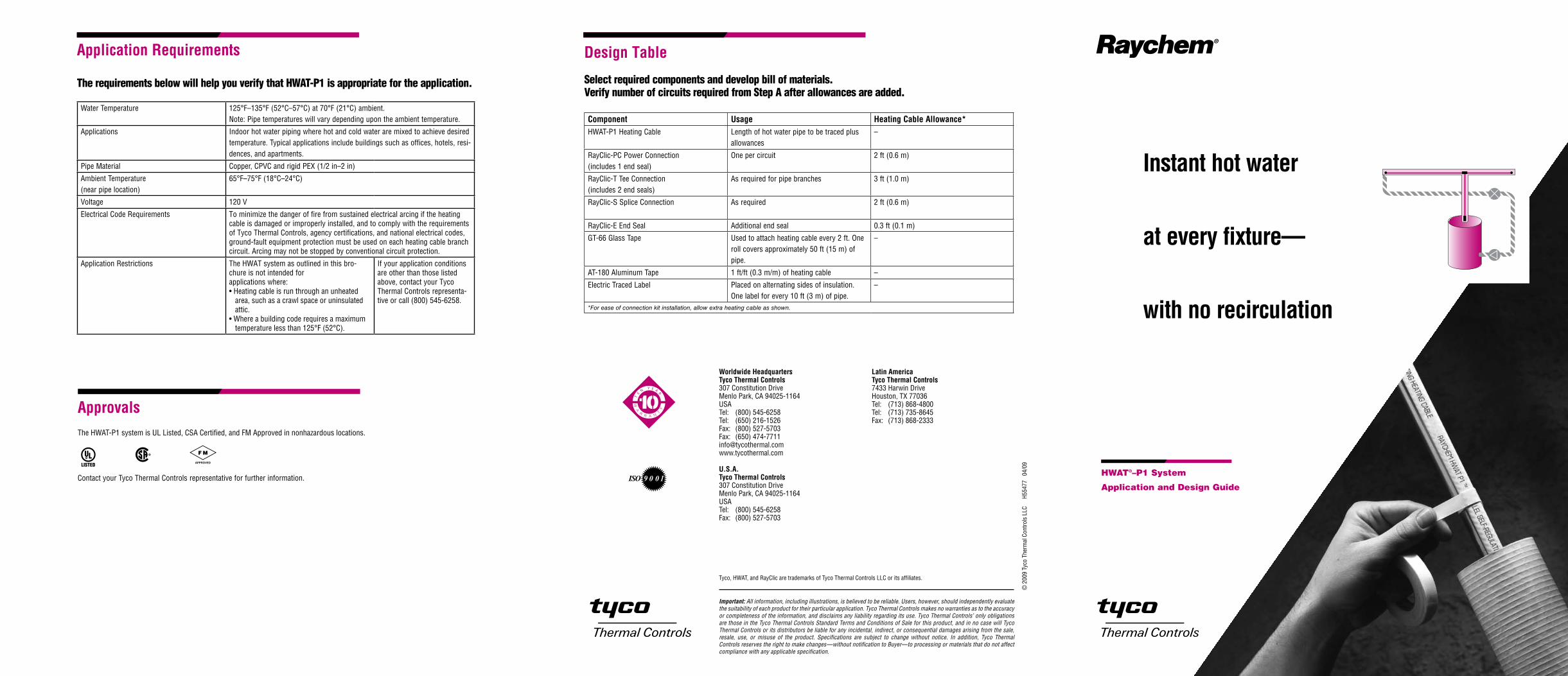
HWAT®–P1 System
Application and Design Guide
Instant hot water
at every fixture—
with no recirculation
Design Table
Select required components and develop bill of materials.Verify number of circuits required from Step A after allowances are added.
Component Usage Heating Cable Allowance*HWAT-P1 Heating Cable Length of hot water pipe to be traced plus
allowances–
RayClic-PC Power Connection(includes 1 end seal)
One per circuit 2 ft (0.6 m)
RayClic-T Tee Connection(includes 2 end seals)
As required for pipe branches 3 ft (1.0 m)
RayClic-S Splice Connection As required 2 ft (0.6 m)
RayClic-E End Seal Additional end seal 0.3 ft (0.1 m)
GT-66 Glass Tape Used to attach heating cable every 2 ft. One roll covers approximately 50 ft (15 m) of pipe.
–
AT-180 Aluminum Tape 1 ft/ft (0.3 m/m) of heating cable –
Electric Traced Label Placed on alternating sides of insulation. One label for every 10 ft (3 m) of pipe.
–
*For ease of connection kit installation, allow extra heating cable as shown.
9 0 01ISO
Important: All information, including illustrations, is believed to be reliable. Users, however, should independently evaluate the suitability of each product for their particular application. Tyco Thermal Controls makes no warranties as to the accuracy or completeness of the information, and disclaims any liability regarding its use. Tyco Thermal Controls’ only obligations are those in the Tyco Thermal Controls Standard Terms and Conditions of Sale for this product, and in no case will Tyco Thermal Controls or its distributors be liable for any incidental, indirect, or consequential damages arising from the sale, resale, use, or misuse of the product. Specifications are subject to change without notice. In addition, Tyco Thermal Controls reserves the right to make changes—without notification to Buyer—to processing or materials that do not affect compliance with any applicable specification.
Tyco, HWAT, and RayClic are trademarks of Tyco Thermal Controls LLC or its affiliates.
© 2
009
Tyco
The
rmal
Con
trols
LLC
H
5547
7 0
4/09
Worldwide HeadquartersTyco Thermal Controls307 Constitution DriveMenlo Park, CA 94025-1164USA Tel: (800) 545-6258 Tel: (650) 216-1526 Fax: (800) 527-5703Fax: (650) [email protected] www.tycothermal.com
U.S.A.Tyco Thermal Controls 307 Constitution DriveMenlo Park, CA 94025-1164USA Tel: (800) 545-6258 Fax: (800) 527-5703
Latin AmericaTyco Thermal Controls 7433 Harwin DriveHouston, TX 77036Tel: (713) 868-4800 Tel: (713) 735-8645Fax: (713) 868-2333
Application Requirements
The requirements below will help you verify that HWAT-P1 is appropriate for the application.
Water Temperature 125°F–135°F (52°C–57°C) at 70°F (21°C) ambient.Note: Pipe temperatures will vary depending upon the ambient temperature.
Applications Indoor hot water piping where hot and cold water are mixed to achieve desired temperature. Typical applications include buildings such as offices, hotels, resi-dences, and apartments.
Pipe Material Copper, CPVC and rigid PEX (1/2 in–2 in)
Ambient Temperature (near pipe location)
65°F–75°F (18°C–24°C)
Voltage 120 V
Electrical Code Requirements To minimize the danger of fire from sustained electrical arcing if the heating cable is damaged or improperly installed, and to comply with the requirements of Tyco Thermal Controls, agency certifications, and national electrical codes, ground-fault equipment protection must be used on each heating cable branch circuit. Arcing may not be stopped by conventional circuit protection.
Application Restrictions The HWAT system as outlined in this bro-chure is not intended for applications where:• Heating cable is run through an unheated
area, such as a crawl space or uninsulated attic.
• Where a building code requires a maximum temperature less than 125°F (52°C).
If your application conditions are other than those listed above, contact your Tyco Thermal Controls representa-tive or call (800) 545-6258.
The HWAT-P1 system is UL Listed, CSA Certified, and FM Approved in nonhazardous locations.
Contact your Tyco Thermal Controls representative for further information.
Approvals
5XL1-CR, -CT5XL2-CR, -CT
8XL1-CR, -CT8XL2-CR, -CT
12XL2-CR, -CT
ELEC
TRIC
TRAC
ED
HWAT-P1 Design Steps
Verify that your application requirements are appropriate for HWAT-P1, then follow these design steps.
A.Identify and measure each circuit, staying within the maximum circuit length.
Circuit Breaker Size (A) Maximum circuit length (ft)
30 500
20 350
15 250
Important: Use a 30-mA ground-fault circuit breaker for each circuit. To minimize the danger of fire from sustained electrical arcing if the heating cable is damaged or improperly installed, and to comply with the requirements of Tyco Thermal Controls, agency certifications, and national electrical codes, ground-fault equipment protec-tion must be used on each heating cable branch circuit. Arcing may not be stopped by conventional circuit protection.
B.Supply proper insulation material and thickness.
Pipe Size (in) Insulation Thickness (in)
1/2–3/4 1/2
1–2 1
• Use only fiberglass or closed cell foam insulation.
• For pipe sizes of 1-1/4 in and smaller use insulation sized for 1/4 in larger pipe.
• When cable is installed on plastic hot water pipes, attach with AT-180 aluminum tape
as shown in the HWAT Installation and Operation Manual (H57548).
C.Use Design Table on back page to select required connection kits and to develop bill of materials.
InstallationFor system installation, testing, and commissioning, the HWAT Installation and Operation Manual (H57548) must be used. Although HWAT-P1 is not specifically mentioned, follow all steps of system testing, operation, and installation outlined in sections 1–5. If you need assistance or a copy of the operation manual, contact Tyco Thermal Controls representative or call (800) 545-6258.
3
4
5
Raychem
RaychemRayClic
WARNING: SHOCK HAZARD
Do not open while energized
®
R
LISTED
DESIG. 3A, 3B, 3C, 2E
3 1/8"
RaychemRayClic
WARNING: SHOCK HAZARD
Do not open while energized
®
R
LISTED
DESIG. 3A, 3B, 3C, 2E
3 1/8"
RaychemRayClic
WARNING: SHOCK HAZARD
Do not open while energized
®
R
LISTED
DESIG. 3A, 3B, 3C, 2E
3 1/8"
2
6
1
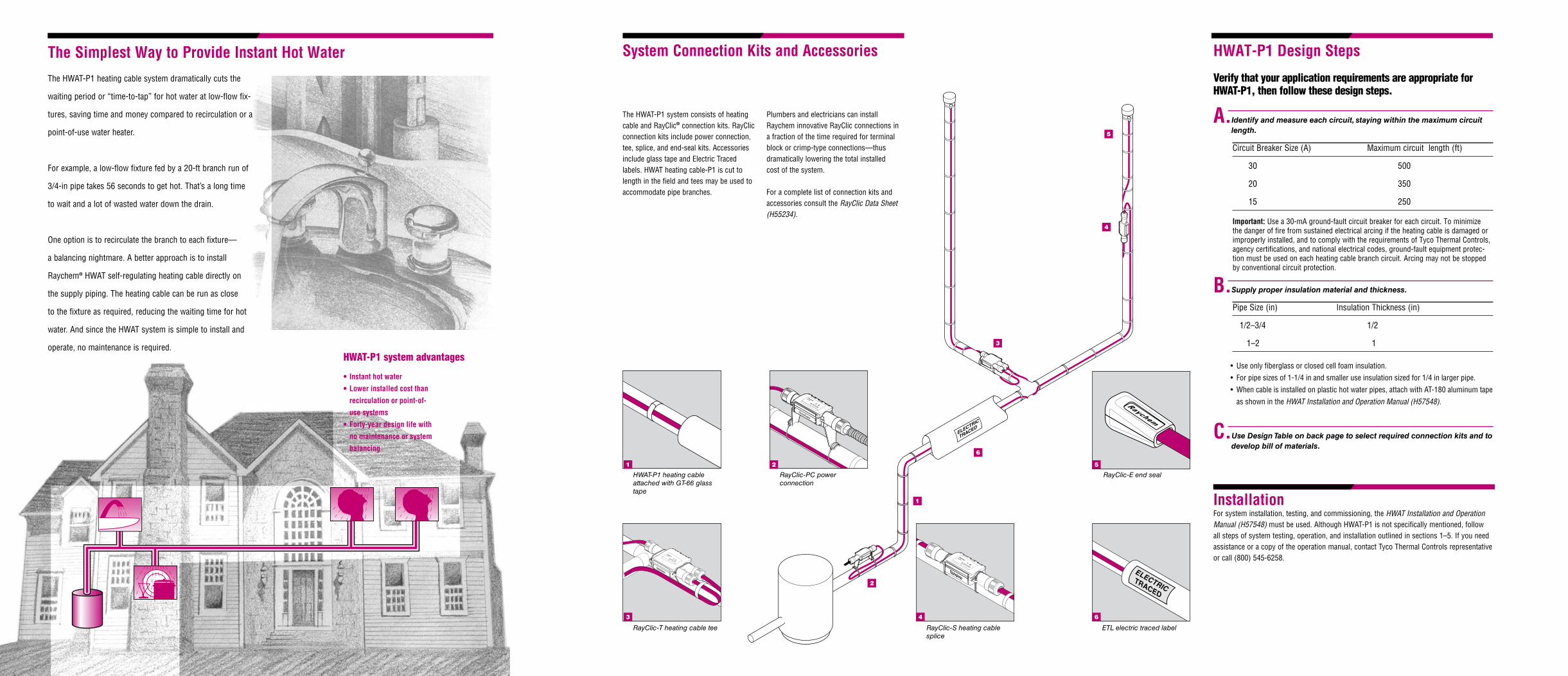
RayClic-PC power connection
2
RayClic-E end seal
5
HWAT-P1 heating cable attached with GT-66 glass tape
1
RayClic-T heating cable tee
3
RayClic-S heating cable splice
4
ETL electric traced label
6
System Connection Kits and Accessories
The HWAT-P1 system consists of heating cable and RayClic® connection kits. RayClic connection kits include power connection, tee, splice, and end-seal kits. Accessories include glass tape and Electric Traced labels. HWAT heating cable-P1 is cut to length in the field and tees may be used to accommodate pipe branches.
Plumbers and electricians can install Raychem innovative RayClic connections in a fraction of the time required for terminal block or crimp-type connections—thus dramatically lowering the total installed cost of the system.
For a complete list of connection kits and accessories consult the RayClic Data Sheet (H55234).
The Simplest Way to Provide Instant Hot Water
• Instanthotwater
•Lowerinstalledcostthan
recirculation or point-of-
use systems
•Forty-yeardesignlifewith
no maintenance or system
balancing
HWAT-P1 system advantages
The HWAT-P1 heating cable system dramatically cuts the
waiting period or “time-to-tap” for hot water at low-flow fix-
tures, saving time and money compared to recirculation or a
point-of-use water heater.
For example, a low-flow fixture fed by a 20-ft branch run of
3/4-in pipe takes 56 seconds to get hot. That’s a long time
to wait and a lot of wasted water down the drain.
One option is to recirculate the branch to each fixture—
a balancing nightmare. A better approach is to install
Raychem® HWAT self-regulating heating cable directly on
the supply piping. The heating cable can be run as close
to the fixture as required, reducing the waiting time for hot
water. And since the HWAT system is simple to install and
operate, no maintenance is required.