Embed Size (px)
Citation preview
U n i v e r s i t ä t A u g s b u r g
Institut fürMathematik
Malte A. Peter, Michael H. Meylan
Water-Wave Scattering by Vast Fields of Bodies
Preprint Nr. 23/2009 — 24. September 2009Institut fur Mathematik, Universitatsstraße, D-86135 Augsburg http://www.math.uni-augsburg.de/
Impressum:
Herausgeber:
Institut fur MathematikUniversitat Augsburg86135 Augsburghttp://www.math.uni-augsburg.de/pages/de/forschung/preprints.shtml
ViSdP:
Malte A. PeterInstitut fur MathematikUniversitat Augsburg86135 Augsburg
Preprint: Samtliche Rechte verbleiben den Autoren c© 2009

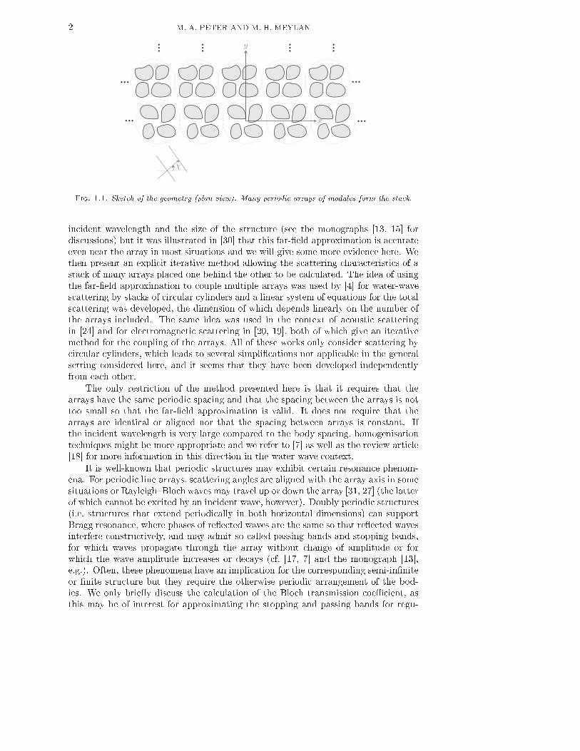
WATER-WAVE SCATTERING BY VAST FIELDS OF BODIESMALTE A. PETER∗ AND MICHAEL H. MEYLAN†Abstract. A very e�cient solution method to the determination of the linear water-wavescattering by a large number of bodies is presented. Several bodies are assembled in modules, whichare grouped in periodic in�nite line arrays. Then, using an iterative method, a �nite number ofthese in�nite arrays are stacked together. The method to calculate the scattering by the in�niteline array of modules of bodies is algebraicly exact while a far-�eld (or wide-spacing) approximationis used in the calculation of the scattering of a �nite stack of arrays. Bloch transmission throughdoubly periodic arrangements of bodies is discussed and so are averaging techniques to suppressphenomena introduced by the periodicity assumption on the line arrays for the case of more orless randomly distributed bodies. While the method is general and can be used in a variety ofsituations, the principle application of the method is to calculate the scattering by vast �elds of ice�oes which occur in the Marginal Ice Zone. Preliminary numerical simulations for �oating elasticplates, modelling ice �oes, are presented and substantiate the applicability of the method.Key words. Water waves, di�raction, multiple arrays, Marginal Ice Zone, Bloch waves.AMS subject classi�cations. 76B15, 86A05, 74F10, 35B10.1. Introduction. We present a computationally e�cient method to calculatethe re�ection and transmission of water waves by vast �elds of bodies within theframework of linear theory. The method is general in the sense that it it is notrestricted to certain types of bodies or body geometries. It is the aim to apply thismethod in the future to approximate the scattering characteristics of the MarginalIce Zone (a region of broken ice which forms at the boundary of the frozen and openocean) without having to assume the problem is two-dimensional. The method isgeneral and is also potentially applicable in a variety of other situations, such asscattering by Very Large Floating Structures supported by many columns or by largeo�-shore wind farms.The idea is brie�y summarised as follows: We calculate the scattering of a large�eld of bodies by �rst grouping several bodies into modules and then determining thescattering characteristics of an in�nite periodic line array of such modules. The �eldof bodies is then assembled by placing many in�nite line arrays behind one anotherin a stack. The solution for this stack is found using a wide-spacing approximation.A sketch of the geometry is given in �gure 1.1.Assuming that the scattering by single bodies can be calculated, an interactiontheory [8, 26] provides an e�cient exact algebraic method for calculating the scatter-ing by �nitely many bodies. Grouping such an arrangement of bodies into a module,the scattering by an in�nite periodic line array of modules is e�ciently calculatedusing the method described in [30]. It is well-known (see [35, 30, 37], e.g.) that thescattered wave�eld away from the array consists of plane waves propagating in a �nitenumber of directions, the so-called scattering angles. Generally, such far-�eld approx-imations (also called wide-spacing or plane-wave approximations; see [5] for a detaileddiscussion in two spatial dimensions) require that the spacing is much larger than the∗Department of Mathematics, University of Auckland, Private Bag 92019, Auckland 1142, NewZealand. Current address: Institute of Mathematics, University of Augsburg, 86135 Augsburg,Germany and Augsburg Centre for Innovative Technologies, University of Augsburg, Germany.([email protected]).†Department of Mathematics, University of Auckland, Private Bag 92019, Auckland 1142, NewZealand ([email protected]). 1
2 M. A. PETER AND M. H. MEYLAN
Fig. 1.1. Sketch of the geometry (plan view). Many periodic arrays of modules form the stack.incident wavelength and the size of the structure (see the monographs [13, 15] fordiscussions) but it was illustrated in [30] that this far-�eld approximation is accurateeven near the array in most situations and we will give some more evidence here. Wethen present an explicit iterative method allowing the scattering characteristics of astack of many arrays placed one behind the other to be calculated. The idea of usingthe far-�eld approximation to couple multiple arrays was used by [4] for water-wavescattering by stacks of circular cylinders and a linear system of equations for the totalscattering was developed, the dimension of which depends linearly on the number ofthe arrays included. The same idea was used in the context of acoustic scatteringin [24] and for electromagnetic scattering in [20, 19], both of which give an iterativemethod for the coupling of the arrays. All of these works only consider scattering bycircular cylinders, which leads to several simpli�cations not applicable in the generalsetting considered here, and it seems that they have been developed independentlyfrom each other.The only restriction of the method presented here is that it requires that thearrays have the same periodic spacing and that the spacing between the arrays is nottoo small so that the far-�eld approximation is valid. It does not require that thearrays are identical or aligned nor that the spacing between arrays is constant. Ifthe incident wavelength is very large compared to the body spacing, homogenisationtechniques might be more appropriate and we refer to [7] as well as the review article[18] for more information in this direction in the water-wave context.It is well-known that periodic structures may exhibit certain resonance phenom-ena. For periodic line arrays, scattering angles are aligned with the array axis in somesituations or Rayleigh�Bloch waves may travel up or down the array [31, 27] (the latterof which cannot be excited by an incident wave, however). Doubly periodic structures(i.e. structures that extend periodically in both horizontal dimensions) can supportBragg resonance, where phases of re�ected waves are the same so that re�ected wavesinterfere constructively, and may admit so-called passing bands and stopping bands,for which waves propagate through the array without change of amplitude or forwhich the wave amplitude increases or decays (cf. [17, 7] and the monograph [13],e.g.). Often, these phenomena have an implication for the corresponding semi-in�niteor �nite structure but they require the otherwise periodic arrangement of the bod-ies. We only brie�y discuss the calculation of the Bloch transmission coe�cient, asthis may be of interest for approximating the stopping and passing bands for regu-
Water-wave scattering by vast �elds of bodies 3larly spaced structures. However, since we are particularly interested in more or lessrandom arrangements of bodies in order to apply this method to scattering in theAntarctic Marginal Ice Zone (MIZ) in the future, we do not investigate any othersuch phenomena in great detail but discuss averaging methods to suppress e�ectsarti�cially introduced by the periodicity instead.The MIZ (Marginal Ice Zone) is an interfacial region which forms at the boundaryof the open and frozen oceans. It consists of vast �elds of ice �oes, which scatter andattenuate the incoming ocean waves. It is of great importance to climate research tounderstand wave propagation and scattering and wave-induced break up in the MIZ(see [34, 33] for more information). Models for wave propagation were developed by[36] based on two-dimensional approximation and this model was developed furtherby [10] and shown to give reasonable agreement with measurements. Three dimen-sional models based on the Boltzmann equation were developed by [16, 25, 23, 22]but these models have proved too complicated to extract geophysical data and so farhave never been used to make comparisons with experiments. We aim to use themethod presented here to create a hybrid two�three dimensional model which willbe su�ciently computationally e�cient that we can determine the attenuation coef-�cients for a range of conditions and to compare this to two-dimensional theory [10]and to experimental measurements [32]. We also note that the present method doesnot depend on the model used for the individual �oe. We use here the ice-�oe modeldeveloped by [21], which is based on an assumption of shallow draft. However, thegenerality of the method allows to use other ice-�oe models, for example accountingfor �nite draught as modelled by [2].The paper is organised as follows: The problem is formulated in detail in �2including the introduction of the required eigenfunctions expansions and di�ractiontransfer operators. The solution method for a module of bodies is discussed in �3and for an in�nite periodic line array of such modules in �4, which also contains adescription of the far �eld and the de�nition of the re�ection and transmission matricesof such an array. The iterative method of stacking up multiple arrays is given in �5.In �6, Bloch transmission in doubly periodic stacks is discussed as well as averagingstrategies to suppress artefacts introduced by the periodicity assumption. Numericalexperiments are conducted in �7, including simulation results for bottom-mountedcylinders and ice �oes. A summary of the results and discussion is given in �8.We also note that a preliminary summary of this paper has appeared in [28].2. Statement of the problem and mathematical formulation. We con-sider the water-wave scattering of a plane wave by vertically non-overlapping bodies.The ambient plane wave is assumed to travel in the given direction χ ∈ (−π, π) whereχ is measured with respect to the x-axis. Let (rj , θj , z) be the local cylindrical coordi-nates of the jth body, ∆j . The global coordinates, centred at the origin, are denotedby (x, y, z) (Cartesian) or (r, θ, z) (cylindrical). A sketch of the geometry is given in�gure 1.1.The equations of motion for the water are derived from the linearised inviscidtheory. Under the assumption of irrotational motion, the velocity-vector �eld of thewater can be written as the gradient �eld of a scalar velocity potential Φ. Assumingthat the motion is time-harmonic with radian frequency ω, the velocity potential canbe expressed as the real part of a complex quantity,
Φ(y, t) = Re {φ(y)e−iωt}. (2.1)To simplify notation, y = (x, y, z) always denotes a point in the water, which is
4 M. A. PETER AND M. H. MEYLANassumed to be of constant �nite depth d, while x always denotes a point of theundisturbed water surface assumed at z = 0.Writing α = ω2/g where g is the gravitational acceleration, the potential φ hasto satisfy the standard boundary-value problem∇2
yφ = 0, y ∈ D, (2.2a)
∂zφ = αφ, x ∈ Γf , (2.2b)∂zφ = 0, y ∈ D, z = −d, (2.2c)where D = (R2 × (−d, 0))\
⋃
j ∆j is the domain occupied by the water and Γf isthe free water surface. At the immersed body surface Γj of ∆j , the water velocitypotential has to equal the normal velocity of the body vj ,∂nφ = vj , y ∈ Γj. (2.2d)A further relationship between the potential and its normal derivative on the bodysurface is required if vj depends of φ, and this comes from the equation of motionfor the body. Moreover, a radiation condition is imposed ensuring that there are onlyoutgoing waves from each scatterer and we denote the ambient incident potential by
φIn. The positive wavenumber k is related to α by the dispersion relationα = k tanh kd, (2.3)and the values of km, m > 0, are given as positive real roots of the dispersion relation
α+ km tan kmd = 0. (2.4)For ease of notation, we write k0 = −ik. Note that k0 is a (purely imaginary) root of(2.4).2.1. Eigenfunction expansion of the potential. The scattered potential ofa body ∆j can be expanded in singular cylindrical eigenfunctions,φS
j (rj , θj , z) =
∞∑
m=0
fm(z)
∞∑
µ=−∞
AjmµKµ(kmrj)e
iµθj , (2.5)with discrete coe�cients Ajmµ, where
fm(z) =cos km(z + d)
cos kmd. (2.6)The incident potential upon body ∆j can be also be expanded in regular cylindricaleigenfunctions,
φIj(rj , θj , z) =
∞∑
n=0
fn(z)
∞∑
ν=−∞
DjnνIν(knrj)e
iνθj , (2.7)with discrete coe�cients Djnν . In these expansions, Iν and Kν denote the modi�edBessel functions of the �rst and second kind, respectively, both of order ν as de�nedin [1]. Note that in (2.5) (and (2.7)) the term for m = 0 (n = 0) corresponds to the
Water-wave scattering by vast �elds of bodies 5propagating modes while the terms for m ≥ 1 (n ≥ 1) correspond to the evanescentmodes.In what follows, it is necessary to represent the ambient wave�eld in the eigenfunc-tion expansion (2.7). This can be accomplished as follows. In Cartesian coordinatescentred at the origin, the ambient wave�eld is given byφIn(x, y, z) =
Ag
ωf0(z)e
ik(x cos χ+y sin χ), (2.8)where A is the amplitude (in displacement) and χ ∈ (−π, π) is the angle betweenthe x-axis and the direction in which the wave�eld travels (also cf. �gure 1.1). Thisexpression can be written in the eigenfunction expansion centred at the origin asφIn(r, θ, z) =
Ag
ωf0(z)
∞∑
ν=−∞
eiν(π−χ)Iν(k0r)eiνθ , (2.9)so that the ambient incident wave�eld has coe�cients
Dnν =
{
Agω (−1)νe−iνχ, n = 0,
0, n > 0in the expansion (2.7). Note that the evanescent coe�cients are all zero due to thepropagating nature of the ambient wave.2.2. Di�raction transfer operators. In what follows, we make extensive useof di�raction transfer operators, sometimes referred to as T-matrices. In general,it is possible to relate the total incident and scattered partial waves for any struc-ture through the di�raction characteristics of that body in isolation. For each body∆j , there exists a di�raction transfer operator Bj that relates the coe�cients of theincident and scattered partial waves, such that
Ajmµ =
∞∑
n=0
∞∑
ν=−∞
BjmnµνD
jnν , (2.10)where Aj contains the amplitudes of the scattered modes due to the incident modesof amplitude Dj . The idea of the di�raction transfer operator is not restricted toa single structure. We can thus associate such an operator with a module. Moregeneral information on di�raction transfer operators can be found in the monograph[15] (referred to as T-matrices therein).Assuming methods for solving the standard scattering problem for each bodyinvolved are available, the corresponding (truncated) di�raction transfer operatorcan be calculated numerically. Di�erent methods are outlined in [6, 9, 30]. For somespecial cases, analytic representations exist. For example, for a rigid bottom-mountedcircular cylinder of radius a, the elements of the di�raction transfer operator are
Bmnµν =
{
−I ′µ(k0a)/K′µ(k0a), 0 ≤ m = n <∞, −∞ < µ = ν <∞,
0, otherwise. (2.11)It is also worth noting that the change in the di�raction transfer operator inducedby a rotation of the body about its mean-centre position is particularly simple [26].
6 M. A. PETER AND M. H. MEYLAN3. Scattering by a �nite number of bodies and grouping into modules.The scattering properties of a �nite number of bodies can be calculated in many di�er-ent ways, for example by using the �nite element method, which involves discretisingall body surfaces, or, more e�ciently, using an interaction theory [8, 26]. For ourpurposes, the scattered wave�eld needs to be represented in terms of eigenfunctionexpansions (2.5) in order to allow the scattering properties to be described by a singledi�raction transfer operator. We brie�y summarise how this can be achieved usingthe interaction theory. Note that the idea of using the interaction theory to groupseveral bodies into modules has been successfully applied previously [9, 3].The interaction theory works by developing a system of equations for the un-known coe�cients (in the expansion (2.5)) of the scattered wave�elds of all bodies.This system of equations is based on transforming the scattered potential of ∆j intoan incident potential upon ∆l, j, l = 1, . . . , N , j 6= l. Doing this for all bodies simul-taneously, and relating the incident and scattered potential for each body, a systemof equations for the unknown coe�cients is developed.The scattered potential φSj of body ∆j needs to be represented in terms of theincident potential φI
l upon ∆l, j 6= l and this can be achieved using Graf's additiontheorem (eq. 9.1.79 in [1]). Since the expansion of the scattered and incident potentialin cylindrical eigenfunctions is only valid outside the escribed cylinder of each body,the escribed cylinder of each body may not contain any other body.Making use of the eigenfunction expansion as well as Graf's addition theorem, thescattered potential of ∆j (cf. (2.5)) can be expressed in terms of the incident potentialin the local coordinates of ∆l asφS
j (rl, θl, z)
=
∞∑
m=0
fm(z)
∞∑
ν=−∞
[
∞∑
τ=−∞
Ajmτ (−1)νKτ−ν(kmRjl)e
i(τ−ν)ϕjl
]
Iν(kmrl)eiνθl , (3.1)where (Rjl, ϑjl) are the coordinates of the mean-centre position of the lth body interms of the coordinate system of the jth body. Let Dl
nν denote the coe�cients of anambient incident wave�eld in the incoming eigenfunction expansion for ∆l (cf. (2.7)).The total incident wave�eld upon body ∆l can now be expressed as in terms of thecoe�cientsDl
nν = Dlnν +
N∑
j=1
j 6=l
∞∑
τ=−∞
Ajnτ (−1)νKτ−ν(knRjl)e
i(τ−ν)ϑjl (3.2)in the expansion (2.7).Using the di�raction transfer operator, the substitution of (3.2) into (2.10) givesthe required equations to determine the coe�cients of the scattered wave�elds of allbodies,Al
mµ =
∞∑
n=0
∞∑
ν=−∞
Blmnµν
[
Dlnν +
N∑
j=1
j 6=l
∞∑
τ=−∞
Ajnτ (−1)νKτ−ν(knRjl)e
i(τ−ν)ϑjl
]
, (3.3)m ∈ N, µ ∈ Z, l = 1, . . . , N .For a given incident wave having coe�cients Dl
nν in the local expansion (2.7),the solution of (3.3) gives the coe�cients Almµ of the scattered wave�eld around eachbody in the expansion (2.5).
Water-wave scattering by vast �elds of bodies 7In order to obtain the di�raction transfer operator of the module made up ofbodies ∆j , j = 1, . . . , N , system (3.3) needs to be solved for all possible incidentwaves of unit amplitude with respect to the origin (i.e. for Dnν = 1 for one (n, ν) at atime and zero for the others). The conversion to the local coordinates of ∆l is givenbyDl
nν =
∞∑
τ=−∞
DnτIτ−ν(knRl)ei(τ−ν)ϑl , (3.4)where (Rl, ϑl) is the mean-centre position of ∆l in polar coordinates and where wehave again utilised Graf's addition theorem. Solving (3.3) for each Dnν , the resultingtotal scattered wave of the modules (with respect to the origin) is similarly given by
Atotmµ =
N∑
l=1
∞∑
τ=−∞
Almτ Iµ−τ (kmRl)e
−i(µ−τ)ϑl , (3.5)from which the elements of the di�raction transfer operator of the module can be reado� directly.4. Scattering by a periodic line array of bodies. In the same way as in theprevious section, the interaction theory can be used to derive a system of equationsfor the periodic line array of identical modules, where the modules have mean-centrepositions (jR, 0), j ∈ Z, and the same di�raction transfer operators M (see [30] fordetails). In this case, system of equations (3.3) becomesAl
mµ =
∞∑
n=0
∞∑
ν=−∞
Mmnµν
[
Dlnν +
∞∑
j=−∞j 6=l
∞∑
τ=−∞
Ajnτ (−1)νKτ−ν(kn|j − l|R)ei(τ−ν)ϕj−l
]
,(4.1)m ∈ N, l, µ ∈ Z, where the angles ϕn account for the di�erence in direction dependingif the jth module is located to the left or to the right of the lth module and are de�nedby
ϕn =
{
π, n > 0,
0, n < 0.Because of the periodicity of the geometry and of the incident wave, the coe�-cients Almµ can be written as Al
mµ = PlA0mµ = PlAmµ, say, where Pl = eilRk cos χ. Thesame can be done for the coe�cients of the incident ambient wave, i.e. Dl
nν = PlDnν .Noting that P−1l = P−l and PjPl = Pj+l, (4.1) simpli�es to
Amµ =
∞∑
n=0
∞∑
ν=−∞
Mmnµν
[
Dnν+(−1)ν∞∑
τ=−∞
Anτ
∞∑
j=−∞j 6=l
Pj−lKτ−ν(kn|j−l|R)ei(τ−ν)ϕj−l
]
.Introducing the constantsσn
ν =
∞∑
j=−∞j 6=l
Pj−lKν(kn|j − l|R)eiνϕj−l =
∞∑
j=1
(P−j + (−1)νPj)Kν(knjR), (4.2)

8 M. A. PETER AND M. H. MEYLANwhich can be evaluated separately since they do not contain any unknowns, the prob-lem reduces toAmµ =
∞∑
n=0
∞∑
ν=−∞
Mmnµν
[
Dnν + (−1)ν∞∑
τ=−∞
Anτ σnτ−ν
]
. (4.3)The e�cient computation of the constants σ0ν is not trivial as the sum in (4.2) is notabsolutely convergent owing to the slow decay of the modi�ed Bessel function of thesecond kind for large imaginary argument (the terms in the sum decay like j−1/2eijθfor some θ). Appropriate methods for the computation of the σ0
ν are outlined in [30]based on results of [11]. The calculation of the constants σnν , n 6= 0, is easy, however,since the modi�ed Bessel function of the second kind decays exponentially for largereal argument.4.1. The far �eld. In this section, the far �eld is examined which describesthe scattering far away from the array. The derivation can be found in [30] and isequivalent to that of [35] for electromagnetic scattering. First, we de�ne the scatteringangles, which give the directions of propagation of plane scattered waves far away fromthe array. Letting p = 2π/R, de�ne the scattering angles χm by
χm = arccos(ψm/k) where ψm = k cosχ+mp (4.4)and write ψ for ψ0. Also note that χ0 = χ by de�nition. If |ψm| < k, i.e. if−1 < cosχ+
mp
k< 1,we say that m ∈ M and then 0 < χm < π. It turns out (see below) that these angles(±χm for m ∈ M) are the directions in which plane waves propagate away from thearray.The only terms which contribute to the far �eld are those for which |ψm| < k.Thus, as y → ±∞, the far �eld consists of a set of plane waves propagating in thedirections θ = ±χm:
φ ∼ φIn +πi
kRf0(z)
∑
m∈M
1
sinχmeikr cos(θ∓χm)
∞∑
µ=−∞
A0µ e±iµχm . (4.5)From (4.5) the amplitudes of the scattered waves for each scattering angle ±χm aregiven in terms of the coe�cients A0µ byA±
m =πi
kR
1
sinχm
∞∑
µ=−∞
A0µ e±iµχm . (4.6)It is implicit in all of the above that sinχm 6= 0 for any m. If sinχm = 0 then wehave the special situation, where one of the scattered plane waves propagates alongthe array. We will not consider this resonant case here, in which the scattered �eldis dominated by waves travelling along the array, either towards x = ∞ (if χm = 0)or towards x = −∞ (if χm = π), and refer to [14] for details. In particular, thisresonance is an artefact of the periodicity assumption.

Water-wave scattering by vast �elds of bodies 94.2. Re�ection and transmission matrices. For given k, R and χ, the far-�eld scattering characteristics of a line array Lj are described by the coe�cients A−mand A+
m, calculated for unit incident potential. If χ is positive, then the amplitudesof the re�ected and transmitted waves travelling away from the array are given byA−
m and δm0 + A+m, respectively. Analogously, for χ negative, the amplitudes of there�ected and transmitted waves respectively are A+
m and δm0 + A−m. (Note that the
A±m may be di�erent for +χ and −χ.)Thus, for given k, R and χ, we de�ne the re�ection and transmission matrices
r+j , t
+j ∈ C#M×#M (where #M denotes the number of elements in the set M), thecolumns of which contain the coe�cients A−
m and δm0 + A+m, respectively, calculatedfor each incident angle +|χn|. These matrices completely describe the far-�eld char-acteristics of the array for the incident wave of angle +|χ|. Analogously, we de�ne
r−j and t
−j having elements A−
m and δm0 + A+m, respectively, calculated for each inci-dent angle −|χn|, for the same situation but with incident angle −|χ|. The classicalscattering matrix is then given by
[
r−j t
+j
t−j r
+j
]
. (4.7)Note that the only di�erence in calculating the elements of r+j and t
+j comparedto r
−j and t
−j is the di�erent right-hand side in (4.3) as one has to use ambient-wavecoe�cients D in one case and the complex conjugated ones D∗ in the other. Thus,when calculating the re�ection and transmission matrices for given χ, there is verylittle extra computational cost to compute them for −χ additionally.If the array is up�down symmetric (i.e. w.r.t. the y-axis), it does not matterwhether the incident wave travels in direction +|χ| or −|χ| and, in this case, the +-and −-re�ection and transmission matrices are identical, i.e. r
−j = r
+j and t
−j = t
+j .It is useful to know how the re�ection and transmission matrices change if thearray undergoes a translation such that the mean-centre position of the zeroth body(originally located at (0, 0)) is shifted to lie at some new position (x, y). Writing
P = dexp(ikx cosχm)c and Q = dexp(iky sinχm)c, where damc is a diagonal matrixwith diagonal elements am, the translation of the array causes the ambient waveincident on the array travelling in positive direction to be phase shifted by PQ. Interms of coordinates centred at (x, y), the re�ection and transmission matrices of theshifted array are thus given by r+j QP and t
+j QP . Keeping in mind that the re�ectedand transmitted waves travel in opposite direction with respect to the y-coordinatebut in the same direction with respect to the x-coordinate, changing the coordinatesback to the origin gives
P−1Qr+j QP and P−1Q−1
t+j QP (4.8)as the re�ection and transmission matrices of the translated array. As expected, a shiftin the x-direction by a multiple of the array spacing R leaves the matrices unchanged.Analogous formulas hold for r
−j and t
−j but are not required in what follows.5. Scattering by multiple line arrays. It was found in [30] that in mostsituations the far-�eld approximation is very good even near the line array and somenumerical experiments con�rming this observation are given in �7. Based on ideasof Mulholland and Heckl [24] for acoustic scattering and McPhedran et al. [20, 19]for electromagnetic scattering, we present an e�cient iterative method to stack upa �nite number of periodic line arrays assuming that the far-�eld approximation is
10 M. A. PETER AND M. H. MEYLANaccurate for the considered stack spacing. It is noteworthy that the previous worksonly consider arrays of circular cylinders and thus arrays having up�down symmetry.It is easy to see from (4.4) that, once k, R and χ are �xed, an incident planewave making an angle χl for a l ∈ M will results in transmitted and re�ected wavestravelling in the directions ±χm, m ∈ M. Thus, for a stack of arrays of the samehorizontal spacing R, only waves in the directions ±χm, m ∈ M, need to be takeninto account.For given k, R and χ, the scattering characteristics of a line array Lj are com-pletely described by the re�ection and transmission matrices r±j , t
±j ∈ C#M×#Mde�ned in �4.2. Assuming that the re�ection and transmission matrices for a stack of
n − 1 arrays is already known, we derive here how to add on an nth array. To keepthings as simple as possible, we only consider ambient waves of given incident angleχ ∈ (0, π) on the stack. Note that this implies no restriction of generality.Let Rn−1 = R
+n−1 and Tn−1 = T
+n−1 respectively be the re�ection and transmis-sion matrices of the stack consisting of n− 1 arrays and let sn > 0 be the (vertical)spacing between the stack and the array to be added on. The phase shift due tomoving the stack along the y-axis such that the array in the stack, whose axis used tocoincide with the x-axis, is now on the line y = sn is encoded in the diagonal matrix
Qn = dexp(iksn sinχm)c (cf. �4.2). The re�ection and transmission matrices of theshifted stack are given by QnRn−1Qn and Q−1n Tn−1Qn, respectively. Now, place aline array characterised by matrices r±n and t±n on the x-axis as illustrated in �gure5.1. Assuming that the far-�eld approximation holds, the amplitudes of the wavestravelling in between the old stack and the new array are
f− = QnRn−1Qnf+, (5.1a)
f+ = t+n δ + r
−n f
− (5.1b)with an incident wave �eld δ on the array. Furthermore, we haveRnδ = r
+n δ + t
−n f
−, (5.2a)Tnδ = Q−1
n Tn−1Qnf+. (5.2b)Eliminating f− and f+, we �nd that the total re�ection and transmission matricesof the stack composed of n arrays is given by
Rn = r+n + t
−nQnRn−1Qn(I − r
−nQnRn−1Qn)−1
t+n , (5.3a)
Tn = Q−1n Tn−1Qn(I − r
−nQnRn−1Qn)−1
t+n . (5.3b)It is noteworthy that placing the new array in front of the stack is necessary inorder to ensure that the scattering characteristics of the stack are only required inone direction. The backward re�ection and transmission matrices, i.e. R− and T−,can be found by an analogous procedure if required.A measure for the total transmitted energy through the stack is given by
Etot =∑
m∈M
|(Tn)m0|2 sinχm, (5.4)where (Tn)m0 is the element (m, 0) of the matrix Tn−1.

Water-wave scattering by vast �elds of bodies 11
Fig. 5.1. Adding on of the nth single line array to the stack already made up of n − 1 arrays(plan view). Shifting the old stack along the y-axis, the re�ection and transmission matrices of theold stack, Rn−1 and Tn−1, become QnRn−1Qn and Q−1n Tn−1Qn with respect to the origin.6. Periodic and random arrangements. Some real-world problems involve aperiodic arrangement of bodies (some o�-shore wind farms or arti�cial breakwaters,e.g.) while in others the distribution is more or less random (ice �oes in the MIZ, e.g.).In the former case, the qualitative scattering behaviour can be well approximated bylooking at the corresponding problem for a doubly-periodic array (i.e. an array whichextends periodically in both horizontal dimensions). This allows to look for Blochwave solutions and �nd the Bloch transmission coe�cient, which gives informationabout passing and stopping bands of the structure. In the latter case, artefacts arti-�cially introduced by periodicity need to be suppressed as much as possible and thisis achieved well by averaging over di�erent arrangements. We will consider these twoscenarios in this section.6.1. Bloch waves and Bloch transmission. We �rst consider the case ofa doubly-periodic array, i.e. an array which extends periodically in both horizontaldimensions. In terms of the notation from the previous sections, we assume that,for given k, R and χ, a single line array with re�ection and transmission matrices
r±, t± ∈ C
#M×#M as de�ned in �4.2 is repeated periodically along the y-axis with�xed period (i.e. vertical spacing) s. The periodicity of the geometry motivates tolook for periodic solutions satisfyingφ(x, y + s, z) = eibsφ(x, y, z). (6.1)Such solutions are sometimes called Bloch waves and the factor eibs is the Blochtransmission coe�cient. The real part of b encodes the phase change as the wavepropagates one period while the imaginary part gives the change in amplitude. In-tervals of ambient wavenumbers k, for which b is real, are known as passing bands,while those, for which b has non-zero imaginary part, are known as stopping bands.It is su�cient to consider only a single line array placed on the x-axis and toenforce periodicity conditions at y = ±s/2,
φ(x, s/2, z) = eibsφ(x,−s/2, z) and ∂yφ(x, s/2, z) = eibs∂yφ(x,−s/2, z). (6.2)
12 M. A. PETER AND M. H. MEYLANA method of determining the value of b for given k, R and χ can be developed asfollows (based on [24]).We adopt the notation from the previous section for wave�elds above and belowthe array (also cf. �g. 5.1) by respectively writing δ+ and δ− for the forward andbackward travelling wave�elds below the array (δ and Rn−1δ in the previous section)and f± for the corresponding ones above the array. Also keeping in mind that thefar-�eld at y = ±s/2 has the form (4.5), conditions (6.2) can be expressed aseibs(δ+ + δ−) = Qf+ +Q−1f− and eibs(δ+ − δ−) = Qf+ −Q−1f−. (6.3)Adding and subtracting these two equations gives
eibsδ+ = Qf+ and eibsδ− = Q−1f−. (6.4)From (5.1b) and (5.2a), we also havef+ = t
+δ+ + r−f− and δ− = r
+δ + t−f−. (6.5)Combining (6.4) and (6.5) to eliminate δ− and f+ eventually leads to
[
Qt+ Qr
−
−(t−)−1r+Qt+ −(t−)−1r+Qr− + (Qt−)−1
] [
δ+
f−
]
= eibs
[
δ+
f−
]
, (6.6)i.e. e±ibs is found by seeking for eigenvalues of the matrix in equation (6.6) (owing tothe symmetry of the problem the eigenvalues appear in pairs of complex conjugates).6.2. Averaging. Since the method for calculating the scattering by a large stackis computationally cheap, it is particularly suitable if the bodies are arranged moreor less randomly and the exact body positions are neither known nor essential. Inthis case, it is important to suppress e�ects arti�cially introduced by the periodicityof the geometry and this can be done by averaging over random samples. This is thestrategy, which is aimed for simulating wave scattering in the MIZ.It is straightforward and computationally very cheap to sample over randomchoices of distances between the line arrays in a stack (i.e. over vertical spacing sn).This only requires multiple runs of the iteration (5.3) but ensures non-periodicity inthe y-direction. The re�ection and transmission matrices of a single line array onlyneed to be calculated once.The next simplest choice is to sample as well over many stacks, each havinga di�erent array spacing of the line array (i.e. over horizontal spacing R). Thisadditionally breaks up the periodicity in the x-direction but requires the calculationof new re�ection and transmission matrices for each sample. The computationalcost is considerably higher than that for the �rst scheme but it is still of manageableextent as the typically most costly operation, the calculation of the di�raction transferoperators, does not need to be carried out multiple times. As all arrays in one stackhave to have the same spacing in order to ensure the same scattering angles, usingarrays with di�erent spacings in the same stack is not sensible.Obviously, there are numerous other possible choices for randomisation and av-eraging. For example, computationally cheap choices are randomly shifting each linearray in the stack by a small distance or randomly rotating modules within each array.We do not follow these ideas here. It will be shown in �7.2 that the approaches abovealready give reasonable agreement with experimental data in the case of ice �oes inthe MIZ.
Water-wave scattering by vast �elds of bodies 13It is also noteworthy that, depending on the application, there might be otherparameters, over which averaging could be performed. For example, it might besensible to average over body properties (size, mechanical properties etc.) as well.We restrict here to averaging over random changes in the body positions, that ischanges in sn and R.The quantity of main interest when considering scattering by ice �oes in the MIZ isthe total transmitted energy, which can be measured by the quantity Etot (cf. (5.4)),and its attenuation. Therefore, we �nd Etot as a function of M , where M is thenumber of line arrays in the stack, for given (constant) horizontal array spacing Rand vertical spacing s or as an average over Z samples of stacks, each sample yieldingan energy Etoti , i = 1, . . . , Z. In this case, Etot =
∑Zi=1 E
toti /Z. If only randomchoices of distances between the line arrays in a stack are considered, each Etot
i iscalculated by choosing each sn, n = 2, . . . ,M , randomly about a mean s with a givenstandard deviation. If random choices of array spacings are also required, each Etotiis calculated by �rst choosing a common spacing for the line arrays in the ith stack(again as a random choice about a mean R with a given standard deviation) and thenchoosing each sn, n = 1, . . . ,M , randomly about a mean s with a given standarddeviation as before.7. Numerical simulations. We present numerical simulations showing sometypical results, which can be obtained by the presented method. Two di�erent bodytypes are considered: the rigid bottom-mounted circular cylinder as a simple modelfor supporting columns of one or more structures or as a breakwater and the �oatingelastic plate of shallow draft as a model for ice �oes. Both models are well-studiedand line arrays of such bodies have already been investigated in detail by the authorsincluding validation and comparison with other results [30, 27].The ice �oes are modelled as thin elastic plates of shallow draft sitting at thewater surface as modelled in [21]. We present results for square ice �oes and circularice �oes. The employed solution method for circular ice �oes is given in [29].7.1. Bottom-mounted circular cylinders. We present some simulations forcircular rigid bottom-mounted cylinders of radius a. This problem is equivalent totwo-dimensional acoustic scattering in a medium with constant sound speed c. The
z-dependence can be omitted and the theory above applies with the following modi-�cations:1. The dispersion relation (2.3) is replaced by k = ω/c where c is the speed ofsound in the medium under consideration and the dispersion relation is (2.4)omitted.2. All factors cos km(z + d), cos kmd and f0 are replaced by 1.Note that the �rst point implies that there are no evanescent modes in this problem,i.e. the sums overm and n in the eigenfunction expansions (2.5) and (2.7), respectively,only contain the terms for m = 0 and n = 0. The di�raction transfer operator is givenby (2.11). Moreover, we have k0 = −iω/c. This problem was considered in detail by[12], e.g.7.1.1. Validity of the far-�eld approximation. We begin by presenting somecomputations illustrating how quickly the far-�eld approximation is accurate in prac-tice. Figure 7.1 shows the real part of the potential along the y-axis calculated using

14 M. A. PETER AND M. H. MEYLAN−4 −3 −2 −1 0 1 2 3 4
−2
−1.5
−1
−0.5
0
0.5
1
1.5
2
y
Re{φ
S(0,y
)}
a = 1, χ = π/3
−4 −3 −2 −1 0 1 2 3 4−2
−1.5
−1
−0.5
0
0.5
1
1.5
2
y
Re{φ
S(0,y
)}
a = 1, χ = π/2
Fig. 7.1. Real part of the potential on the y-axis. Thick lines show the full potential calculatedvia (7.1) while thin lines correspond to the far-�eld approximation (4.5) for incident angle π/3 (left)and π/2 (right). The cylinder radius is a is 1 and the other data is given by λ = 1.8, R = 3 (solidlines), λ = 1.8, R = 4 (dashed lines), λ = 2.5, R = 3 (dotted lines) and λ = 2.5, R = 4 (dash-dottedlines).the full solution (thick lines), i.e.φS =
∞∑
j,µ=−∞
PjA0µKµ(k0rj)eiµθj , (7.1)and the far-�eld approximation given by (4.5) (thin lines) for di�erent parametervalues. It can be seen that the far-�eld approximation and the full solution becomesimilar quickly away from the array axis (they are nearly indistinguishable at y = ±2for all cases) implying that the approximation is valid even near the array. It can beseen that the approximation is generally more accurate for perpendicular incidence(χ = π/2). The comparison of the imaginary parts of the potential (not shown) givesanalogous results.7.1.2. Impact of distribution of cylinder radii. We investigate what impacta change in the distribution of the cylinders has. For this purpose, we consider modulesof two adjacent cylinders of di�erent radii a1 and a2. We choose a1 = 0.25, 0.5, 0.75, 1and a2 accordingly such that the sum of the cross-sectional areas is always equal to
2π, i.e. a2 =√
2 − a21. Obviously, a1 = 1 implies a2 = 1, i.e. the two cylinders areidentical in this case and this is in fact equivalent to a line array of single cylinderswith half the spacing, which we consider in the next section.We choose the line-array spacing R = 6 and consider the total re�ection of astack of two and eight of such line arrays over a range of incident wavenumbers. Theincident angle is χ = π/3 in all cases and the stack spacing in sn = 5.It can be seen that the general behaviour of the curves is more or less the samefor all cylinder radius distributions, particularly for small wavenumber. This is tobe expected since the long waves do not interact as strongly with the objects. It isinteresting to note that there is a sharp spike around k = 0.7 for all cylinder radiusdistributions except for the case where the cylinders are identical.7.1.3. Bloch transmission in a fully periodic stack. We want to investigatehow well the Bloch transmission approximates the transmission by a �nite numberof arrays. For this purpose, we consider the setting with eight arrays of identicalcylinders from the previous section and compare this to the corresponding Bloch
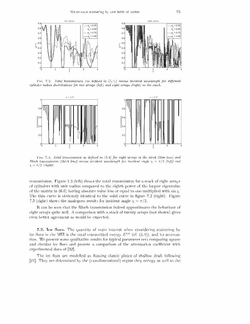
Water-wave scattering by vast �elds of bodies 150 1 2 3 4
0
0.1
0.2
0.3
0.4
0.5
0.6
0.7
0.8
0.9two arrays
k
|Eto
t |
a1 = 0.25
a1 = 0.50
a1 = 0.75
a1 = 1.00
0 1 2 3 40
0.1
0.2
0.3
0.4
0.5
0.6
0.7
0.8
0.9eight arrays
k
|Eto
t |
a1 = 0.25
a1 = 0.50
a1 = 0.75
a1 = 1.00
Fig. 7.2. Total transmission (as de�ned in (5.4)) versus incident wavelength for di�erentcylinder radius distributions for two arrays (left) and eight arrays (right) in the stack.0 1 2 3 4
0
0.2
0.4
0.6
0.8
1χ = π/3
k
tran
smis
sion
0 1 2 3 40
0.2
0.4
0.6
0.8
1
k
tran
smis
sion
χ = π/2
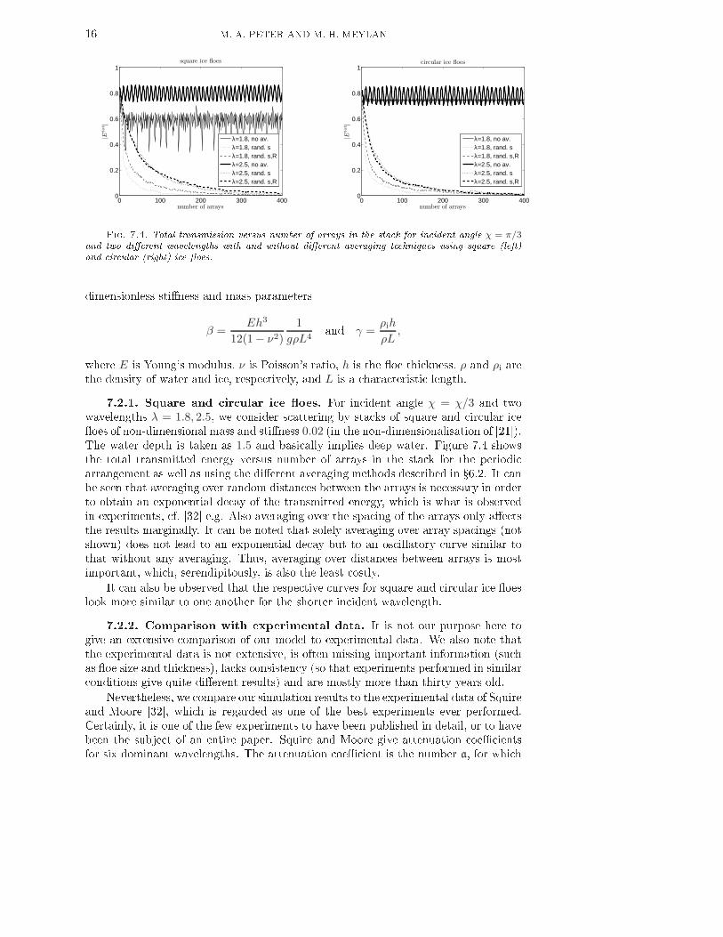
Fig. 7.3. Total transmission as de�ned in (5.4) for eight arrays in the stack (thin line) andBloch transmission (thick line) versus incident wavelength for incident angle χ = π/3 (left) andχ = π/2 (right).transmission. Figure 7.3 (left) shows the total transmission for a stack of eight arraysof cylinders with unit radius compared to the eighth power of the largest eigenvalueof the matrix in (6.6) having absolute value less or equal to one multiplied with sinχ.The thin curve is obviously identical to the solid curve in �gure 7.2 (right). Figure7.3 (right) shows the analogous results for incident angle χ = π/2.It can be seen that the Bloch transmission indeed approximates the behaviour ofeight arrays quite well. A comparison with a stack of twenty arrays (not shown) giveseven better agreement as would be expected.7.2. Ice �oes. The quantity of main interest when considering scattering byice �oes in the MIZ is the total transmitted energy Etot (cf. (5.4)), and its attenua-tion. We present some qualitative results for typical parameter sets comparing squareand circular ice �oes and present a comparison of the attenuation coe�cient withexperimental data of [32].The ice �oes are modelled as �oating elastic plates of shallow draft following[21]. They are determined by the (two-dimensional) region they occupy as well as the
16 M. A. PETER AND M. H. MEYLAN0 100 200 300 400
0
0.2
0.4
0.6
0.8
1
number of arrays
|Eto
t |
square ice floes
λ=1.8, no av.λ=1.8, rand. sλ=1.8, rand. s,Rλ=2.5, no av.λ=2.5, rand. sλ=2.5, rand. s,R
0 100 200 300 4000
0.2
0.4
0.6
0.8
1
number of arrays
|Eto
t |
circular ice floes
λ=1.8, no av.λ=1.8, rand. sλ=1.8, rand. s,Rλ=2.5, no av.λ=2.5, rand. sλ=2.5, rand. s,RFig. 7.4. Total transmission versus number of arrays in the stack for incident angle χ = π/3and two di�erent wavelengths with and without di�erent averaging techniques using square (left)and circular (right) ice �oes.dimensionless sti�ness and mass parameters
β =Eh3
12(1 − ν2)
1
gρL4and γ =
ρih
ρL,where E is Young's modulus, ν is Poisson's ratio, h is the �oe thickness, ρ and ρi arethe density of water and ice, respectively, and L is a characteristic length.7.2.1. Square and circular ice �oes. For incident angle χ = χ/3 and twowavelengths λ = 1.8, 2.5, we consider scattering by stacks of square and circular ice�oes of non-dimensional mass and sti�ness 0.02 (in the non-dimensionalisation of [21]).The water depth is taken as 1.5 and basically implies deep water. Figure 7.4 showsthe total transmitted energy versus number of arrays in the stack for the periodicarrangement as well as using the di�erent averaging methods described in �6.2. It canbe seen that averaging over random distances between the arrays is necessary in orderto obtain an exponential decay of the transmitted energy, which is what is observedin experiments, cf. [32] e.g. Also averaging over the spacing of the arrays only a�ectsthe results marginally. It can be noted that solely averaging over array spacings (notshown) does not lead to an exponential decay but to an oscillatory curve similar tothat without any averaging. Thus, averaging over distances between arrays is mostimportant, which, serendipitously, is also the least costly.It can also be observed that the respective curves for square and circular ice �oeslook more similar to one another for the shorter incident wavelength.7.2.2. Comparison with experimental data. It is not our purpose here togive an extensive comparison of our model to experimental data. We also note thatthe experimental data is not extensive, is often missing important information (suchas �oe size and thickness), lacks consistency (so that experiments performed in similarconditions give quite di�erent results) and are mostly more than thirty years old.Nevertheless, we compare our simulation results to the experimental data of Squireand Moore [32], which is regarded as one of the best experiments ever performed.Certainly, it is one of the few experiments to have been published in detail, or to havebeen the subject of an entire paper. Squire and Moore give attenuation coe�cientsfor six dominant wavelengths. The attenuation coe�cient is the number a, for which
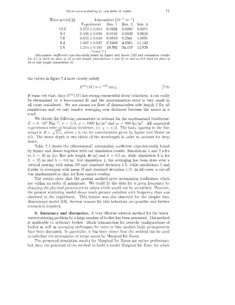
Water-wave scattering by vast �elds of bodies 17Wave period [s] Attenuation [10−4 m−1]Experiment Sim. 1 Sim. 2 Sim. 312.2 0.272± 0.054 0.0258 0.0005 0.00119.4 0.438± 0.036 0.0102 0.0032 0.06587.6 0.855± 0.049 0.6310 0.2341 1.00316.4 1.087± 0.037 6.2480 4.6381 11.1425.5 1.214± 0.192 19.392 24.153 12.825Table 7.1Attenuation coe�cient experimentally found by Squire and Moore [32] and simulation resultsfor 0.5 m thick ice �oes of 40 m side length (simulations 1 and 2) as well as 0.6 thick ice �oes of50 m side length (simulation 3).the curves in �gure 7.4 most closely satisfyEtot(M) ≈ e−aM sinχ. (7.2)It turns out that, since Etot(M) has strong exponential-decay behaviour, a can easilybe determined by a least-square �t and the approximation error is very small inall cases considered. We use square ice �oes of dimensionless side length 2 for allsimulations and we only employ averaging over distances between the arrays in astack.We choose the following parameters to account for the experimental conditions:
E = 6 · 109 Nm−2, ν = 1/3, ρ = 1000 kg/m3 and ρi = 900 kg/m3. All numericalexperiments refer to head-on incidence, i.e. χ = π/2. The body spacing in the linearrays is R =√
4/c, where c is the ice concentration given by Squire and Moore as0.5. The water depth is two thirds of the wavelength in order to account for deepwater.Table 7.1 shows the (dimensional) attenuation coe�cient experimentally foundby Squire and Moore together with our simulation results. Simulations 1 and 2 referto L = 20 m (i.e. �oe side length 40 m) and h = 0.5 m, while simulation 3 is forL = 25 m and h = 0.6 m. For simulation 1, the averaging has been done over avertical spacing with mean 2R and standard deviation 1.5, while simulations 2 and3 refer to averaging with mean R and standard deviation 1/3. In all cases, a cut-o�was implemented so that ice �oes cannot overlap.The results show that the present method gives attenuation coe�cients whichare within an order of magnitude. We could �t the data for a given frequency bychanging the physical parameters to values which would not be unrealistic. However,the present scattering model shows much greater variation with frequency than wasobserved in the experiment. This feature was also observed for the simpler two-dimensional model [10]. Several reasons for this behaviour are possible and furtherresearch is required.8. Summary and discussion. A very e�cient solution method for the water-wave-scattering problem by a large number of bodies has been presented. The methodis applicable to arbitrary bodies. Bloch transmission for periodic con�gurations ofbodies as well as averaging techniques for more or less random body arrangementshave been discussed. In particular, it has been shown how the method can be usedto calculate the attenuation of ocean waves by Marginal Ice Zones.The presented simulation results for Marginal Ice Zones are rather preliminarybut show the potential of the method to build a model Marginal Ice Zone, for which
18 M. A. PETER AND M. H. MEYLANsimulations are feasible. It is also worth pointing out that the discussed averagingtechniques are highly parallelisable although this is probably not necessary. Moreresearch needs to be undertaken to �nd out whether it is sensible to average over othermodel parameters as well, such as the ice �oe geometry, size, material parameters andso on. Moreover, the in�uence of the particular ice �oe model is worth examining.Such investigations will be presented in future publications.It is noteworthy that, because of the e�ciency of the method, it is also easy toincorporate further observed properties of Marginal Ice Zones, such as a changingdenseness in the ice cover or a changing thickness of the ice as functions of distancefrom the ice edge. Moreover, the evolution of the directional spectrum can also beextracted from the simulation results.Acknowledgements. We would like to thank Luke Bennetts (University ofOtago) for the numerous fruitful discussions during this research. This research wassupported by Marsden grant UOO308 from the New Zealand government.REFERENCES[1] M. Abramowitz and I.A. Stegun, eds., Handbook of Mathematical Functions, Dover Inc.New York, 1964.[2] L. G. Bennetts, N. R. T. Biggs, and D. Porter, Wave scattering by an axisymmetric ice�oe of varying thickness, IMA J. Appl. Math., (2008). doi:10.1093/imamat/hxn019.[3] S. Chakrabarti, Hydrodynamic interaction forces on multi-moduled structures, Ocean Engng,27 (2000), pp. 1037�1063.[4] R. A. Dalrymple, S. N. Seo, and P. A. Martin,Water wave scattering by rows of circularcylinders, in Proc. Int. 21st Coastal Engng Conf., Malaga, Spain, B. L. Edge, ed., 1988,pp. 2216�2228.[5] D. V. Evans, The wide-spacing approximation applied to multiple scattering and sloshingproblems, J. Fluid Mech., 210 (1990), pp. 647�658.[6] J.-S. Goo and K. Yoshida, A numerical method for huge semisubmersible responses inwaves, SNAME Transactions, 98 (1990), pp. 365�387.[7] X. Hu and C. T. Chan, Refraction of water waves by periodic cylinder arrays, Phys. Rev.Lett., 95 (2005), p. 154501.[8] H. Kagemoto and D. K. P. Yue, Interactions among multiple three-dimensional bodies inwater waves: an exact algebraic method, J. Fluid Mech., 166 (1986), pp. 189�209.[9] M. Kashiwagi, Hydrodynamic interactions among a great number of columns supporting avery large �exible structure, J. Fluids Struct., 14 (2000), pp. 1013�1034.[10] A. Kohout and M. H. Meylan, An elastic plate model for wave attenuation and ice �oebreaking in the marginal ice zone, J. Geophys. Res., 113 (2008).[11] C. M. Linton, The Green's function for the two-dimensional Helmholtz equation in periodicdomains, J. Engng. Math., 33 (1998), pp. 377�402.[12] C. M. Linton and D. V. Evans, The interaction of waves with a row of circular cylinders,J. Fluid Mech., 251 (1993), pp. 687�708.[13] C. M. Linton and P. McIver, Handbook of Mathematical Techniques for Wave / StructureInteractions, Chapman & Hall /CRC, 2001.[14] C. M. Linton and I. Thompson, Resonant e�ects in scattering by periodic arrays, WaveMotion, 44 (2008), pp. 165�175.[15] P. A. Martin, Multiple scattering. Interaction of time-harmonic waves with N obstacles,Cambridge University Press, 2006.[16] D. Masson and P. H. LeBlond, Spectral evolution of wind-generated surface gravity wavesin a dispersed ice �eld, J. Fluid Mech., 202 (1989), pp. 111�136.[17] P. McIver, Water-wave propagation through an in�nite array of cylindrical structures, J.Fluid Mech., 424 (2000), pp. 101�125.[18] , Wave interaction with arrays of structures, Appl. Ocean Res., 24 (2002), pp. 121�126.[19] R. C. McPhedran, L. C. Botten, A. A. Asatryan, N. A. Nicorovici, C. M. de Sterke,and P. A. Robinson, Ordered and disordered photonic band gap materials, Aust. J. Phys.,52 (1999), pp. 791�809.[20] R. C. McPhedran, L. C. Botten, A. A. Asatryan, N. A. Nicorovici, P. A. Robinson,
Water-wave scattering by vast �elds of bodies 19and C. M. de Sterke, Calculation of electromagnetic properties of regular and randomarrays of metallic and dielectric cylinders, Phys. Rev. E, 60 (1999), pp. 7614�7617.[21] M. H. Meylan,Wave response of an ice �oe of arbitrary geometry, J. Geophys. Res. � Oceans,107 (2002), p. doi: 10.1029/2000JC000713.[22] M. H. Meylan and D. Masson, A linear Boltzmann equation to model wave scattering inthe marginal ice zone, Ocean Modelling, 11 (2006), pp. 417�427.[23] M. H. Meylan, V. A. Squire, and C. Fox, Towards realism in modeling ocean wave behaviorin marginal ice zones, J. of Geophysical Research, 102 (1997), pp. 22981�22991.[24] L. S. Mulholland and M. A. Heckl, Multi-directional sound wave propagation through atube bundle, J. Sound Vibration, 176 (1994), pp. 377�398.[25] W. Perrie and Y. Hu, Air�ice�ocean momentum exchange. part 1:energy transfer betweenwaves and ice �oes, J. of Phys. Ocean., 26 (1996), pp. 1705�1720.[26] M. A. Peter and M. H. Meylan, In�nite-depth interaction theory for arbitrary �oatingbodies applied to wave forcing of ice �oes, J. Fluid Mech., 500 (2004), pp. 145�167.[27] , Water-wave scattering by a semi-in�nite periodic array of arbitrary bodies, J. FluidMech., 575 (2007), pp. 473�494.[28] ,Water-wave scattering of vast �elds of bodies such as ice �oes in the Marginal Ice Zone,in Proc. 24th Int. Workshop on Water Waves and Floating Bodies, Zelenogorsk, Russia,A. Korobkin and P. Plotnikov, eds., 2009. in press.[29] M. A. Peter, M. H. Meylan, and H. Chung, Wave scattering by a circular elastic platein water of �nite depth: a closed form solution, IJOPE, 14 (2004), pp. 81�85.[30] M. A. Peter, M. H. Meylan, and C. M. Linton, Water-wave scattering by a periodicarray of arbitrary bodies, J. Fluid Mech., 548 (2006), pp. 237�256.[31] R. Porter and D. V. Evans, Rayleigh-Bloch surface waves along periodic gratings and theirconnection with trapped modes in waveguides, J. Fluid Mech., 386 (1999), pp. 233�258.[32] V.A. Squire and S. C. Moore, Direct measurement of the attentuation of ocean waves bypack ice, Nature, 283 (1980), pp. 365 � 368.[33] V. A. Squire, Of ocean waves and sea-ice revisited, Cold Regions Science and Technology, 49(2007), pp. 110�133.[34] V. A. Squire, J. P. Dugan, P. Wadhams, P. J. Rottier, and A. J. Liu, Of ocean wavesand sea ice, Annu. Rev. Fluid Mech., 27 (1995), pp. 115�168.[35] V. Twersky, On scattering of waves by the in�nite grating of circular cylinders, IRE Trans.on Antennas and Propagation, 10 (1962), pp. 737�765.[36] P. Wadhams, V. A. Squire, D. J Goodman, A. M. Cowan, and S. C. Moore, Theattenuation rates of ocean waves in the marginal ice zone, J. Geophys. Res., 93 (1988),pp. 6799 � 6818.[37] C. D. Wang, M. H. Meylan, and R. Porter, The linear wave response of a periodic arrayof �oating elastic plates, J. Engng Math., 57 (2007), pp. 23�40.