Embed Size (px)
Citation preview
INSTITUTE OF AERONAUTICAL ENGINEERING (Autonomous)
Dundigal, Hyderabad -500 043
MECHANICAL ENGINEERING
TUTORIAL QUESTION BANK
Course Title MATERIALS AND MECHANICS OF SOLIDS
Course Code AMEB11
Programme B. Tech
Semester IV ME
Course Type Core
Regulation IARE - R18
Course Structure
Theory Practical
Lectures Tutorials Credits Laboratory Credits
3 1 4 - -
Chief Coordinator Dr. K. Viswanath Allamraju, Professor
Course Faculty Dr. K. Viswanath Allamraju, Professor
Mr. A Somaiah, Assistant Professor
COURSE OBJECTIVES:
The course should enable the students to:
I Understand the nature of stresses developed in simple geometries such as bars, cantilevers, beams,
shafts, cylinders and spheres for various types of loads
II Calculate the elastic deformation occurring in various simple geometries for different types of
loading.
COURSE OUTCOMES (COs):
CO 1 Understand the basic crystallography, dislocation, yield point phenomenon and re crystallization.
CO 2 Understand the alloys and phase diagrams.
CO 3 Describe elastic constants and principal planes.
CO 4 Understand shear force and bending moment diagrams, flexural stresses and shear stresses.
CO 5 Understand slope and deflection by using double integration and Maxwell’s reciprocal theorems.
COURSE LEARNING OUTCOMES (CLOS):
S. No. Description
AMEB11.01 Analyze the structure of materials at different levels, basic concepts of crystalline
materials like unit cell, FCC, BCC, HCP, Atomic packing factor, Coordinate number etc.
AMEB11.02 Explain the necessity of alloying, types of solid solution and intermediate alloy phases.
AMEB11.03 Explain the concept of phase and phase diagram and understand the basic terminologies
associated with metallurgy.
AMEB11.04 Construction of phase diagrams and identification of different phases and invariant
reaction.
AMEB11.05 Understand and suggest the heat treatment processes and types, and significance of
mechanical and metallurgical properties with respect to microstructures.
AMEB11.06 Explain the concept of Hardenability and demonstrate the test used to find the
Hardenability of steels.
AMEB11.07 Analyze the microstructure of metallic materials using phase diagram and modify the
microstructure and properties using different heat treatment processes.
AMEB11.08 Define and differentiate engineering materials on the basis of structure and properties for
engineering applications.
AMEB11.09 Discuss Hook’s law, stress and strain.
AMEB11.10 Define elastic constants such as young’s modulus, rigidity modulus , bulk modulus and poison’s ratio.
AMEB11.11 Understand principal stresses and strains.
AMEB11.12 Understand Mohr’s circle method for finding principal stresses.
AMEB11.13 Discuss Beams and their reactions for determining shear force and bending moments.
AMEB11.14 Define shear force and bending moment and their sign conventions.
AMEB11.15 Understand flexural stresses of various cross sections of beams.
AMEB11.16 Understand shear stresses of various cross sections of beams.
AMEB11.17 Discuss slope and deflection.
AMEB11.18 Define moment of inertia and polar moment of inertia.
AMEB11.19 Understand deflection of a beam by double integration method.
AMEB11.20 Discuss Maxwell’s reciprocal theorem.
TUTORIAL QUESTION BANK
MODULE- I
BASIC CONCEPTS AND FIRST LAW OF THERMODYNAMICS
Part - A (Short Answer Questions)
S No QUESTIONS Blooms
Taxonomy
Level
Course
Outcomes
Course
Learning
Outcomes
(CLOs)
1 Define Crystallography. Remember CO 1 AMEB11.01
2 Define unit cell. Understand CO 1 AMEB11.01
3 Define space lattice. Remember CO 1 AMEB11.01
4 Define alloy. Remember CO 1 AMEB11.01
5 Define grain boundary. Remember CO 1 AMEB11.01
6 Draw the miller indices plane for (100). Remember CO 1 AMEB11.01
7 Draw the miller indices plane for (101). Remember CO 1 AMEB11.02
8 Draw the miller indices plane for (110). Remember CO 1 AMEB11.02
9 Draw the miller indices plane for (111). Remember CO 1 AMEB11.02
10 Draw the miller indices plane for ( 10). Remember CO 1 AMEB11.02
11 What is Point defect? Remember CO 1 AMEB11.02
12 What is Line defect? Remember CO 1 AMEB11.03
13 What is Surface defect? Understand CO 1 AMEB11.03
14 What is Volume defect? Understand CO 1 AMEB11.03
15 What is Dislocation? Remember CO 1 AMEB11.03
16 Define the term Alloy. Understand CO 1 AMEB11.03
17 Define the term Phase. Understand CO 1 AMEB11.04
18 Define the term Solid solution. Remember CO 1 AMEB11.04
19 Define the term Intermediate phase. Understand CO 1 AMEB11.04
20 Define the term Electron compound. Remember CO 1 AMEB11.04
Part - B (Long Answer Questions)
1 Define grain and grain boundary? What are the characteristics of grain boundary?
Remember CO 1 AMEB11.01
2 What is grain size? What are the methods for determining grain
size?
Understand CO 1 AMEB11.01
3 Explain effect of grain size on properties. Understand CO 1 AMEB11.01
4 State and explain Hume Rothery rules for the formation of solid
solutions
Remember CO 1 AMEB11.01
5 What are intermediate phases? What are the various types of
intermediate phases?
Understand CO 1 AMEB11.01
6 What is a crystalline material? Distinguish between single crystal
material and polycrystalline material?
Understand CO 1 AMEB11.01
7 Define the terms (i) Space lattice ( ii) unit cell (iii) solid solution
and monotectic solution
Understand CO 1 AMEB11.03
8 Explain the procedure to find out the miller indices with an
example.
Remember CO 1 AMEB11.03
9 Draw the miller indices for (i)(100) (ii)(110)( iii)(111). Understand CO 1 AMEB11.03
10 List out and draw various bravias lattice structures and their
primitives.
Remember CO 1 AMEB11.03
11 Write the relation between a,b,c and α,β,γ in cubic crystal system,
tetragonal crystal system, orthorhombic crystal system and
Hexagonal crystal system.
Understand CO 1 AMEB11.03
12 Define packing factor? What is the packing factor for (i) Simple
cubic crystal (ii)Body centred cubic crystal.
Remember CO 1 AMEB11.03
13 What is effective number of atoms? Calculate the effective Understand CO 1 AMEB11.03
number of atoms in SC structure, FCC structure, BCC structure.
14 What is the relation between lattice constant (a) and atomic
radius(r) in SC structure, FCC structure, BCC structure, HCP
structure?
Understand CO 1 AMEB11.03
15 Define coordination number. What is the coordination number for
BCC, FCC,HCP,(Explain with proper procedure)?
Understand CO 1 AMEB11.03
16 What is the necessity of alloying? Remember CO 1 AMEB11.03
17 Write briefly about Humme Rothery rules. Understand CO 1 AMEB11.03
18 What are solid solutions? Remember CO 1 AMEB11.03
19 What are the types of solid solutions? Understand CO 1 AMEB11.03
20 What is linear atomic density? Calculate the linear atomic density
in [110] direction in the cooper crystal lattice in atoms per mm.
copper is FCC and has a lattice constant of 0.351.
Understand CO 1 AMEB11.03
Part - C (Problem Solving and Critical Thinking Questions)
1 Compare cubic and body centred cubic crystal. Remember
CO 1 AMEB11.02
2 What is coordination number? Understand
CO 1 AMEB11.02
3 What is atomic packing factor? Remember CO 1 AMEB11.02
4 Compare covalent and ionic bond. Remember CO 1 AMEB11.03
5 What is metallic bond? Understand CO 1 AMEB11.03
6 Compare coarse and fine grain structure. Remember CO 1 AMEB11.03
7 Compare point and line defects. Understand CO 1 AMEB11.03
8 Compare pure metals and alloys. Understand CO 1 AMEB11.03
9 Compare substitutional and interstitial solid solutions. Remember CO 1 AMEB11.03
10 What is melting range in alloys? Remember CO 1 AMEB11.03
MODULE- II
ALLOYS AND PHASE DIAGRAMS
PART - A (SHORT ANSWER QUESTIONS)
1 Define the term Binary alloy. Understand CO 2 AMEB11.05
2 Define phase. Understand CO 2 AMEB11.07
3 Define Gibbs Rule. Understand CO 2 AMEB11.05
4 Define levers rule. Understand CO 2 AMEB11.07
5 Define the term coring. Remember CO 2 AMEB11.05
6 Define Isomorphous system. Understand CO 2 AMEB11.05
7 Define Eutectic system. Remember CO 2 AMEB11.07
8 Define Partial eutectic system. Understand CO 2 AMEB11.05
9 Define Peritectic system. Understand CO 2 AMEB11.09
10 Define Monotectic system. Understand CO 2 AMEB11.07
11 What is melting range? Remember CO 2 AMEB11.09
12 Define Phase Diagram. Remember CO 2 AMEB11.05
13 What are the types of substitutional solid solutions? Understand CO 2 AMEB11.05
14 What is Substitutional solid solution? Understand CO 2 AMEB11.05
15 Define cooling curve. Understand CO 2 AMEB11.05
16 Define Eutectoid reaction. Remember CO 2 AMEB11.09
17 What is Thermal Equilibrium Diagram? Remember CO 2 AMEB11.07
18 Draw the stages of structures from Solid to Liquid formation in
binary system.
Remember CO 2 AMEB11.05
19 What are the examples of intermediate phases? Remember CO 2 AMEB11.05
20 What is the use of cooling curves? Remember CO 2 AMEB11.05
PART - B (LONG ANSWER QUESTIONS)
1 Explain with the help of a diagram the cooling curve of pure
metals.
Understand CO 2 AMEB11.05
2 State and explain levers rule. Understand CO 2 AMEB11.07
3 Explain with the help of a diagram the cooling curve of
alloys.
Understand CO 2 AMEB11.07
4 State and explain Gibbs phase rule. Understand CO 2 AMEB11.07
5 Explain the construction of phase diagram. Understand CO 2 AMEB11.09
6 Explain about non equilibrium cooling. Understand CO 2 AMEB11.09
7 Write in brief about the binary phase diagram. Understand CO 2 AMEB11.05
8 What is the purpose of phase diagrams? Understand CO 2 AMEB11.09
9 Define the term isomorphism and polymorphism. Understand CO 2 AMEB11.09
10 Explain about the isomorphous system with a Ni-Cu
diagram.
Understand CO 2 AMEB11.09
11 Write a brief note about eutectic system. Understand CO 2 AMEB11.05
12 Explain the phase change in a eutectic system with an
example.
Understand CO 2 AMEB11.07
13 Write a short note on eutectoid system. Understand CO 2 AMEB11.07
14 Explain with an example the eutectoid system. Understand CO 2 AMEB11.09
15 What are dendrites? Understand CO 2 AMEB11.07
16 Explain the formation of dendrites. Understand CO 2 AMEB11.09
17 What are the most common types of phase diagrams explain in
brief?
Understand
CO 2 AMEB11.05
18 Draw and explain the Cd-Bi phase diagram.
19 Draw and explain the cooling curves for pure metals.
20 Explain about the levers rule and write its application. Understand CO 2 AMEB11.07
Part - C (Problem Solving and Critical Thinking Questions)
1 Compare eutectic and peritectic reaction. Understand
CO 2 AMEB11.07
2 Compare eutectic and eutectoid reaction. Understand
CO 2 AMEB11.07
3 What is peritectoid reaction? Understand
CO 2 AMEB11.09
4 Compare peritectoid and eutectoid reaction. Understand
CO 2 AMEB11.09
5 What is a phase? Understand
CO 2 AMEB11.09
6 What is Gibbs phase rule? Understand
CO 2 AMEB11.05
7 Compare phase and component. Understand
CO 2 AMEB11.05
8 Compare isomorphous and eutectic system. Understand
CO 2 AMEB11.09
9 What is coring? Understand
CO 2 AMEB11.09
10 What are intermediate phases? Understand
CO 2 AMEB11.05
MODULE -III
SIMPLE STRESSES AND STRAINS , PRINCIPAL STRESSES
Part - A (Short Answer Questions)
1 Define stress and strain Remember CO 3 AMEB11.13
2 List the different types of stress Remember CO 3 AMEB11.13
3 List the different types of strain Understand CO 3 AMEB11.13
4 State Hooke’s law Remember CO 3 AMEB11.13
5 Define thermal stress Remember CO 3 AMEB11.13
6 What do you mean by bar of uniform strength. Understand CO 3 AMEB11.13
7 Define bulk modulus Understand CO 3 AMEB11.13
8 Define shear modulus Remember CO 3 AMEB11.13
9 Define modulus of elasticity Understand CO 3 AMEB11.13
10 Define longitudinal strain? Understand CO 3 AMEB11.13
11 What is principal stress? Understand CO 3 AMEB11.15
12 What is principal plane? Remember CO 3 AMEB11.15
13 What is normal stress? Remember CO 3 AMEB11.11
14 What is tangential stress? Understand CO 3 AMEB11.11
15 Explain maximum principal stress theory? Remember CO 3 AMEB11.11
16 What is maximum principal strain theory? Remember CO 3 AMEB11.11
17 Explain maximum strain energy theory? Understand CO 3 AMEB11.11
18 What is maximum shear strain energy theory? Remember CO 3 AMEB11.15
19 What are the theories of failure? Remember CO 3 AMEB11.15
20 What is the stress on a plane inclined at an angle ɵ? Understand CO 3 AMEB11.11
Part – B (Long Answer Questions)
1 Draw stress and strain diagram for mild steel. Indicate salient points and define them
Understand CO 3 AMEB11.13
2 Derive the relation between E, K and G. Understand CO 3 AMEB11.13
3 Derive the relation between E, K and Poisson’s ratio. Understand CO 3 AMEB11.13
4 Derive the relation between Poisson’s ratio, K and G. Understand CO 3 AMEB11.13
5 What is bulk modulus? Derive an expression for young’s
modulus interms of bulk modulus and poisons ration.
Understand CO 3 AMEB11.13
6 A bar of 25 mm diameter is tested in tension. It is observed that when a load of 60kN is applied, the extension measured over a gauge length of 200 mm is 0.12 mm and contraction in diameter is 0.0045 mm. Find Poisson’s ratio and elastic constants E, G, K.
Understand CO 3 AMEB11.13
7 A circular rod of 25 mm diameter and 500 mm long is subjected to a tensile force of 60 kN. Determine modulus of rigidity, bulk modulus and change in volume if Poisson’s ratio is 0.3 and Young’s modulus E = 2 × 10⁵ N/mm2.
Understand
CO 3 AMEB11.13
8 A 400 mm long bar has rectangular cross-section 10 mm × 30 mm. This bar is subjected to (i) 15 kN tensile force on 10 mm × 30 mm faces, (ii) 80 kN compressive force on 10 mm × 400 mm faces, and (iii) 180 kN tensile force on 30 mm × 400 mm faces. Find the change in volume if E = 2 × 10⁵ N/mm2 and µ= 0.3.
Understand CO 3 AMEB11.13
9 In a laboratory, tensile test is conducted and Young’s modulus of the material is found to be 2.1 × 10⁵ N/mm2. On the same material torsion test is conducted and modulus of rigidity is found to be 0.78 × 10⁵ N/mm2. Determine Poisson’s Ratio and bulk modulus of the material.
Understand CO 3 AMEB11.13
10 A material has modulus of rigidity equal to 0.4 × 10⁵ N/mm2 and bulk modulus equal to 0.8 × 10⁵ N/mm2. Find its Young’s Modulus and Poisson’s Ratio.
Understand
CO 3 AMEB11.14
11 Derive equations for normal stress, shear stress and resultant stress on a plane the normal to which is inclined at 30s to the axis of the bar.
Understand CO 3 AMEB11.15
12 A tie bar is subjected to a uniform tensile stress of 100N/mm2. Find the intensity of normal stress, shear stress and resultant stress on a plane the normal to which is inclined to the axis at 300 to the axis of the bar. Also estimate the max shear stress in the bar.
Understand CO 3 AMEB11.15
13 Describe an equation for normal and shear stress when a material is subjected to biaxial stresses P1 and P2.
Understand CO 3 AMEB11.15
14 A piece of material is subjected to tensile stresses of 70N/ mm2 and 50N/mm2 at right angles to each other. Find the stresses on a plane the normal of which makes an angle 350 with the 70N/ mm2 stress.
Understand CO 3 AMEB11.15
15 Explain maximum principal stress theory and indicate the materials for which it is suitable.
Understand CO 3 AMEB11.11
16 An element in a plane is subjected to stresses P1=120N/ mm2 P2=45N/ mm2 (both tensile and perpendicular to each other) and shearing stress of 30N/ mm2. Determine the stresses on a plane normal to which is inclined to the stress 120N/ mm2 at an
Understand CO 3 AMEB11.15
angle 450.
17 Explain the construction of Mohr’s circle for two like stresses P1 and P2.
Understand CO 3 AMEB11.15
18 A piece of material is subjected to tensile stresses of 70N/mm2 and 30N/mm2 at right angles to each other. Find the stresses on a plane the normal of which makes an angle of 400 with the 70N/mm2 stress.
Understand CO 3 AMEB11.15
19 A piece of material is subjected to stresses P1 and P2 (both tensile and mutually perpendicular) and a shear stress q.
Indicate the principal stresses and their positions.
Understand CO 3 AMEB11.11
20 At a point in an elastic material under strain, normal stresses
60N/mm2 and 40N/mm2 (both tensile and right angles to each
other) with a shearing stress 20N/mm2. Find
The principal stresses and their position
Maximum shear stress and its plane
Understand CO 3 AMEB11.11
Part – C (Problem Solving and Critical Thinking)
1 A bar of rectangular section shown in is subjected to stresses px, py and pz in x, y and z directions respectively. Show that if sum
of these stresses is zero, there is no change in volume of the bar.
Understand
CO 3 AMEB11.13
2 A bar of 30 mm diameter is tested in tension. It is observed that
when a load of 70kN is applied, the extension measured over a
guage length of 100 mm is 0.15 mm and contraction
in diameter is 0.0045 mm. Find Poisson’s ratio and elastic
constants E, G, K.
Understand
CO 3 AMEB11.13
3 What are the applications of elastic constants in research?
Explain briefly.
Understand CO 3 AMEB11.13
4 A bar 30 mm in diameter and 200mm long was subjected to an
axial pull of 60 kN. The extension of the bar was found to be
0.1 mm, while decrease in the diameter was found to be 0.004
mm. Find the Young’s modulus, Poisson’s ratio, rigidity
modulus and bulk
modulus of the material of the bar.
Understand CO 3 AMEB11.13
5 A round bar 40 mm diameter is subjected to an axial pull of
80KN and reduction in diameter was found to be
0.00775mm. Find poison’s ratio and young’s modulus for the
material of the bar. Take
value of shear modulus as 40 GPa
Understand CO 3 AMEB11.13
06 The stresses at a point in a component are 100 mpa tensile and 50 mpa compressive. Determine the magnitude of the normal and shear stresses on a plane inclined at an angle of 250 with tensile stress. Also determine the direction of the resultant stress and thje magnitude of the maximum intensity of shear stress.
Understand CO 3 AMEB11.15
07 A plane element in a body is subjected to a tensile stress of 100MPA accopained by a clock shear stress of 25 Mpa. Find (i) the normal and shear stress on a plane inclined at an angle 200 with the tensile stress; and (ii) the maximum shear stress on the plane.
Understand CO 3 AMEB11.15
08 At a point in a strained material, the principal stresses are 100Mpa ad 50 MPa both tensile. find the normal ad shear stresses at a section at 600 with the axis of the major principle stresses.
Understand CO 3 AMEB11.15
09 An element is a strained body is subjected to a tensile stress of 150Mpa ad a shear of 50Mpa tending to rotate the element in a anticlockwise direction. find (i) the magnitude of the normal and shear stresses a section inclined at 400 with the tensile stress and (ii) the magnitude ad direction of maximum shear stress that ca exit on the element
Understand CO 3 AMEB11.11
10 A plane element in a body is subjected to a tensile stress of 100Mpa accompanied by a clockwise shear stress of 25Mpa. Find
Understand CO 3 AMEB11.15
(i) The normal shear stress on a inclined plane at an angle of 200 with the tensile stress; and (ii) the maximum shear stress on the plane.
MODULE -IV
SHEAR FORCE AND BENDING MOMENT DIAGRAMS, FLEXURAL STRESS , SHEAR STRESSES
Part – A (Short Answer Questions)
1 Define Shear force? Remember CO 4 AMEB11.16
2 What are the different types of beams? Remember CO 4 AMEB11.16
3 What are the different types of loads acting on the beam Remember CO 4 AMEB11.16
4 What are the sign conventions to be followed for shear force and
bending moment
Remember CO 4 AMEB11.16
5 How many points of contra flexure you will have for a
simplysupported beam overhanging at one end only?
Understand CO 4 AMEB11.16
6 Differentiate between a point load and an UDL Remember CO 4 AMEB11.16
7 What is the maximum b.m in a simply supported beam with point load at center?
Understand CO 4 AMEB11.16
8 What is meant by section modulus? Understand CO 4 AMEB11.16
9 What is the differential relation between bending moment, shear force and the applied load?
Understand CO 4 AMEB11.16
10 Sketch the shear stress variation for symmetrical I section Understand CO 4 AMEB11.16
11 What do you meant by point of contra flexure? Remember CO 4 AMEB11.16
12 What is meant by moment of resistance of a beam? Understand CO 4 AMEB11.18
13 Write any two assumptions in the theory of simple bending. Understand CO 4 AMEB11.19
14 What is equivalent section Understand CO 4 AMEB11.17
15 What is pure bending Remember CO 4 AMEB11.18
16 What is strength of section Understand CO 4 AMEB11.17
17 Define modular ratio Understand CO 4 AMEB11.18
18 Define the terms: section modulus, fletched beams Remember CO 4 AMEB11.19
19 Explain shear stress in a beam Remember CO 4 AMEB11.18
20 Write formula for shear stress in a beam and indicate the parameters including units
Understand CO 4 AMEB11.19
Part – B (Long Answer Questions)
1 A cantilever beam AB, 1.8 m long carries a point load of 2.5 KN at its free end and a uniformly distributed load of 1KN/m from A to B. Draw shear force and bending moment diagrams for the beam.
Understand CO 4 AMEB11.16
2 A simply supported beam of 3 m span carries two loads of 5 KN each at 1 m and 2 m from the left hand support. Draw shear force and bending moment diagrams for the beam.
Understand CO 4 AMEB11.16
3 Draw SFD and BMD for a Cantilever Subject to a Concentrated Load at Free End
Understand CO 4 AMEB11.16
4 Draw SFD and BMD for a Cantilever Subject to UDL Over its Entire Span
Understand CO 4 AMEB11.16
5 A Beam of length 6.0m is simply supported at the ends and carries a u.d.l of intensity 1.5KN/m run and three concentrated loads of 1KN, 2KN and 3KN acting at a distance of 1.5m, 3.0m and 4.5m respectively from left end. Draw the S.F.D and B.M.D and also determine the maximum bending moment.
Understand CO 4 AMEB11.16
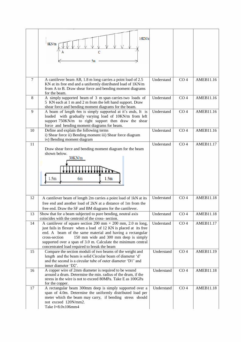
6 The intensity of loading on a simply supported beam of 5.0m
span increases uniformly from 8KN/m at one end to 16KN/m
at the other end as shown in Fig.1. Find the position and
magnitude of the maximum bending moment. Also draw
S.F.D and B.M.D.
Understand CO 4 AMEB11.16
7 A cantilever beam AB, 1.8 m long carries a point load of 2.5 KN at its free end and a uniformly distributed load of 1KN/m from A to B. Draw shear force and bending moment diagrams for the beam.
Understand CO 4 AMEB11.16
8 A simply supported beam of 3 m span carries two loads of 5 KN each at 1 m and 2 m from the left hand support. Draw shear force and bending moment diagrams for the beam.
Understand CO 4 AMEB11.16
9 A beam of length 6m is simply supported at it’s ends, It is
loaded with gradually varying load of 10KN/m from left support 750KN/m to right support then draw the shear
force and bending moment diagrams for beam.
Understand CO 4 AMEB11.16
10 Define and explain the following terms
i) Shear force ii) Bending moment iii) Shear force diagram iv) Bending moment diagram
Understand CO 4 AMEB11.16
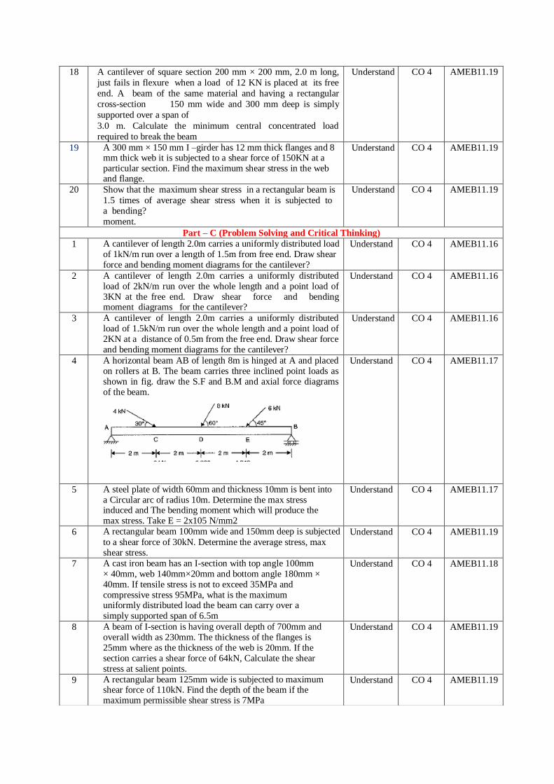
11
Draw shear force and bending moment diagram for the beam
shown below.
Understand CO 4 AMEB11.17
12 A cantilever beam of length 2m carries a point load of 1kN at its
free end and another load of 2kN at a distance of 1m from the
free end. Draw the SF and BM diagrams for the cantilever.
Understand CO 4 AMEB11.18
13 Show that for a beam subjected to pure bending, neutral axis coincides with the centroid of the cross- section.
Understand CO 4 AMEB11.18
14 A cantilever of square section 200 mm × 200 mm, 2.0 m long,
just fails in flexure when a load of 12 KN is placed at its free
end. A beam of the same material and having a rectangular cross-section 150 mm wide and 300 mm deep is simply
supported over a span of 3.0 m. Calculate the minimum central
concentrated load required to break the beam
Understand CO 4 AMEB11.17
15 Compare the section moduli of two beams of the weight and
length and the beam is solid Circular beam of diameter ‘d’
and the second is a circular tube of outer diameter ‘D1’ and
inner diameter ‘D2’.
Understand CO 4 AMEB11.19
16 A copper wire of 2mm diameter is required to be wound around a drum. Determine the min. radius of the drum, if the stress in the wire is not to exceed 80MPa. Take E as 100GPa for the copper.
Understand CO 4 AMEB11.18
17 A rectangular beam 300mm deep is simply supported over a
span of 4.0m. Determine the uniformly distributed load per
meter which the beam may carry, if bending stress should
not exceed 120N/mm2.
Take I=8.0x106mm4
Understand CO 4 AMEB11.18
18 A cantilever of square section 200 mm × 200 mm, 2.0 m long,
just fails in flexure when a load of 12 KN is placed at its free
end. A beam of the same material and having a rectangular
cross-section 150 mm wide and 300 mm deep is simply
supported over a span of
3.0 m. Calculate the minimum central concentrated load
required to break the beam
Understand CO 4 AMEB11.19
19 A 300 mm × 150 mm I –girder has 12 mm thick flanges and 8 mm thick web it is subjected to a shear force of 150KN at a particular section. Find the maximum shear stress in the web and flange.
Understand CO 4 AMEB11.19
20 Show that the maximum shear stress in a rectangular beam is
1.5 times of average shear stress when it is subjected to a bending?
moment.
Understand CO 4 AMEB11.19
Part – C (Problem Solving and Critical Thinking)
1 A cantilever of length 2.0m carries a uniformly distributed load of 1kN/m run over a length of 1.5m from free end. Draw shear force and bending moment diagrams for the cantilever?
Understand CO 4 AMEB11.16
2 A cantilever of length 2.0m carries a uniformly distributed load of 2kN/m run over the whole length and a point load of 3KN at the free end. Draw shear force and bending moment diagrams for the cantilever?
Understand CO 4 AMEB11.16
3 A cantilever of length 2.0m carries a uniformly distributed load of 1.5kN/m run over the whole length and a point load of 2KN at a distance of 0.5m from the free end. Draw shear force and bending moment diagrams for the cantilever?
Understand CO 4 AMEB11.16
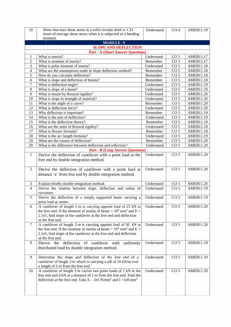
4 A horizontal beam AB of length 8m is hinged at A and placed on rollers at B. The beam carries three inclined point loads as shown in fig. draw the S.F and B.M and axial force diagrams of the beam.
Understand CO 4 AMEB11.17
5 A steel plate of width 60mm and thickness 10mm is bent into a Circular arc of radius 10m. Determine the max stress induced and The bending moment which will produce the max stress. Take E = 2x10⁵ N/mm2
Understand CO 4 AMEB11.17
6 A rectangular beam 100mm wide and 150mm deep is subjected
to a shear force of 30kN. Determine the average stress, max shear stress.
Understand CO 4 AMEB11.19
7 A cast iron beam has an I-section with top angle 100mm × 40mm, web 140mm×20mm and bottom angle 180mm × 40mm. If tensile stress is not to exceed 35MPa and compressive stress 95MPa, what is the maximum uniformly distributed load the beam can carry over a simply supported span of 6.5m
Understand CO 4 AMEB11.18
8 A beam of I-section is having overall depth of 700mm and overall width as 230mm. The thickness of the flanges is 25mm where as the thickness of the web is 20mm. If the section carries a shear force of 64kN, Calculate the shear stress at salient points.
Understand CO 4 AMEB11.19
9 A rectangular beam 125mm wide is subjected to maximum shear force of 110kN. Find the depth of the beam if the maximum permissible shear stress is 7MPa
Understand CO 4 AMEB11.19
10 Show that max shear stress in a solid circular shaft is 1.33 times of average shear stress when it is subjected to a bending moment.
Understand CO 4 AMEB11.19
MODULE -V
SLOPE AND DEFLECTION
Part - A (Short Answer Questions)
1 What is inertia? Understand CO 5 AMEB11.17
2 What is moment of inertia? Remember CO 5 AMEB11.17
3 What is polar moment of inertia? Understand CO 5 AMEB11.18
4 What are the assumptions made in slope deflection method? Remember CO 5 AMEB11.18
5 How do you calculate deflection? Remember CO 5 AMEB11.18
6 What is slope and deflection of beams? Remember CO 5 AMEB11.18
7 What is deflection angle? Understand CO 5 AMEB11.19
8 What is slope of a beam? Understand CO 5 AMEB11.19
9 What is meant by flexural rigidity? Understand CO 5 AMEB11.20
10 What is slope in strength of material? Understand CO 5 AMEB11.20
11 What is the angle of a curve? Remember CO 5 AMEB11.20
12 What is deflection force? Understand CO 5 AMEB11.20
13 Why deflection is important? Remember CO 5 AMEB11.19
14 What is the unit of deflection? Understand CO 5 AMEB11.19
15 What is the deflection theory? Remember CO 5 AMEB11.19
16 What are the units of flexural rigidity? Understand CO 5 AMEB11.18
17 What is flexure formula? Remember CO 5 AMEB11.18
18 What is the arc length formula? Understand CO 5 AMEB11.19
19 What are the causes of deflection? Remember CO 5 AMEB11.20
20 What is the difference between deflection and reflection? Understand CO 5 AMEB11.20
Part - B (Long Answer Questions)
1 Derive the deflection of cantilever with a point load at the free end by double integration method.
Understand CO 5 AMEB11.20
2 Derive the deflection of cantilever with a point load at
distance ‘a’ from free end by double integration method.
Understand CO 5 AMEB11.20
3 Explain briefly double integration method. Understand CO 5 AMEB11.20
4 Derive the relation between slope, deflection and radius of curvature.
Understand CO 5 AMEB11.19
5 Derive the deflection of a simply supported beam carrying a
point load at center.
Understand CO 5 AMEB11.19
6 A cantilever of length 3 m is carrying appoint load of 25 kN at
the free end. If the moment of inertia of beam = 108 mm4 and E =
2.1e5, find slope of the cantilever at the free end and deflection
at the free end.
Understand CO 5 AMEB11.20
7 A cantilever of length 3 m is carrying appoint load of 50 kN at
the free end. If the moment of inertia of beam = 108 mm4 and E =
2.1e5, find slope of the cantilever at the free end and deflection
at the free end.
Understand CO 5 AMEB11.20
8 Derive the deflection of cantilever with uniformly distributed load by double integration method.
Understand CO 5 AMEB11.19
9 Determine the slope and deflection of the free end of a
cantilever of length 3 m which is carrying a udl of 10 kN/m over
a length of 2 m from the free end.
Understand CO 5 AMEB11.19
10 A cantilever of length 3 m carries two point loads of 2 kN at the
free end and 4 kN at a distance of 1 m from the free end. Find the
deflection at the free end. Take E – 2e5 N/mm2 and I =1e8 mm4
Understand CO 5 AMEB11.20
Prepared by: Mr. A. Venuprasad, Assistant Professor HOD, ME
11 Explain briefly Maxwells reciprocal theorem. Understand CO 5 AMEB11.20
12 Explain the methods of determining beams deflections. Understand CO 5 AMEB11.20
13 Understand CO 5 AMEB11.20
14 Understand CO 5 AMEB11.20
15 Understand CO 5 AMEB11.19
16 Understand CO 5 AMEB11.20
17 Understand CO 5 AMEB11.20
18 A cantilever of length 3 m is carrying appoint load of 35 kN at
the free end. If the moment of inertia of beam = 108 mm4 and E =
3.1e5, find slope of the cantilever at the free end and deflection
at the free end.
Understand CO 5 AMEB11.20
19 Determine the slope and deflection of the free end of a cantilever
of length 3 m which is carrying a udl of 20 kN/m over a length of
1 m from the free end.
Understand CO 5 AMEB11.20
20 Understand CO 5 AMEB11.20
Part – C (Problem Solving and Critical Thinking)
1
Understand CO 5 AMEB11.19
2 Understand CO 5 AMEB11.18
3 Understand CO 5 AMEB11.19
4 Understand CO 5 AMEB11.18
5 Understand CO 5 AMEB11.19
6 Understand CO 5 AMEB11.20
7 Understand CO 5 AMEB11.20
8 Understand CO 5 AMEB11.19
9 Understand CO 5 AMEB11.20
10 Understand CO 5 AMEB11.20