Embed Size (px)
Citation preview

INSTltUCTIONS FOR DRILLING TUBEWELLS WlTI-I THE VONDER RIG
THE VONDER RIG MANUFACTURED BY
V. & W. Engineering (Pvt.) Ltd. P.O. BOX 131
HARARE ZIMBABWE

ACKNOVLEDGEKEMNTS
TilE DEVELOP KENT OF TilE VONDER RIG IS THE RESULT OF THE SKILL AND ENTHUSIASM OF ITS DESIGNER HR ERWIN VON ELLIBG OF V & W ENGINEERING AND IllSTALLATIONS IN HARARE. THE VONDER RIG HAS CONTRIBUTED GREATLY TO THE STATE OF THE ART OF HAND DRILLED TUBEWELLS AND HAS MADE A REALITY OF FULL SCALE COMHUNITY PARTICIPATION IN THE EXCAVATION OF GROUNDWATER. I GREATLY ACKNOWLEDGE THE WORK OF HR VON ELLING AND HIS STAFF ON THIS FINE
ACHIEVEMENT . TilE CLEAR ILLUSTRATIONS INCLUDED III THIS MANUAL ARE THE WORK OF COLLEEN COUS INS, AND HAVE BEEN TAKEN FROM EDUCATIONAL MATERIAL DEVELOPED BY HRS SUE LAVER ON STEP BY STEP INSTRUCTIONS FOR USING A HAND OPERATED DRILLING RIG . THEIR CONTRIBUTION, SUPPORTED BY GTZ IS GREATLY
APPREC I H ED. ACKNOWLEDGEME NT IS ALSO DUE TO THE PUBLIC HEALTH INSPECTORATE AND THEIR STAFF WHO HAVE PROMOTED THE USE OF HAND DRILLED TUBEWELLS IN THEIR AREAS AND ALSO TilE BtAIR RESEARCH TEAKS WIIO HAVE DEVELOPED A KNOWLEDGE OF THE RIG AND PASSED ON THEIR KNOWLEDGE TO FIELD TEAKS ALL OVER THE COUNTRY
PRI!
BLAIR RESEARCH LABORATORY HARARE
JULY 1988

HAND DRILLED TUBE_ELLS
111 t hough the wide diameter well is the most common type of E'xc avatlon for penetrating shallow water tables in Zimbabwe, and most other developing countries, this is being replaced more and more w 1 th ni1 r row diameter wells called tubewells. Host boreholes d r llled with mechanised rigs can be decribed as tubewells, and these often penetrate into very deep aquifers where water is found in fra c tured rock layers.
Where water is abundant in the "overburden" above the rock layer, it is possible to drill a shallow borehole, or tubewell by hand, provided the ground is suitable. If the water table lies within about 6 metres of the surface, and the ground is fairly soft, th i s can be drilled with a standard post auger attached to standard 25mm water piping and turned with wrench spanners. Several hand operated drilling rigs have been designed throughout the world, but one of the best was designed at V and W Enginee r ing in Harare. This machine, called the Vonder Rig, represents a significant advance in hand operated drilling rig design, and has pushed the state of the art very much forward.
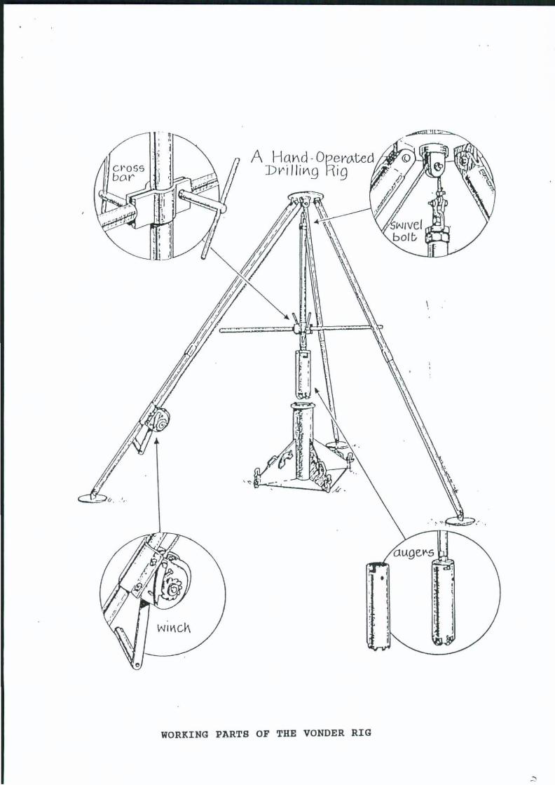
The Vonder Rig is illustrated on the next page and consists of a sturdy tripod from which the drilling stems are slung. The heart of the rig is a robust worktable, which aligns the drilling auger and makes possible the drilling of vertical tubewells down to a depth of over 35 metres in the ground. The auger itself c onsists of a steel tube fitted with hard steel blades, for c utting and lifting soil. The auger is attached to the lowest drilling stem by means of a bayonet adaptor. The auger and drilling stems are raised and lowered with a winch which is attached to one leg of the tripod. Several types of auger are available, one being a hole saw which can penetrate decomposing rocks like decomposing granite. The Vonder Rig was designed to drill through soils and decomposing rock formations, but not through hard rock. The manufacturers, V and W Enginineering, P.O. Box 131, Harare, Zimbabwe, supply the following items with each drilling package:
1. Worktable with plumb line for levelling 2. Tripod with hand winch and cable 3. lIuger (for soft soils) 4. Hole saw (for decomposing rock formations) 5. Bayonet adaptor for augers 6. Cross bar for turning stems 7. Bailer B. B X 2 metre heavy duty drilling stems with acme threads 9. stem stand with oil can 10.Heavy duty spanner for ' tightening stems
PERFORMJI.NCE
The Vonder Rig drills 170mm diameter holes. The time to unload, assemble on site is approximately 30 minutes. The initial drilling rate in average soil conditions should be 3.0 metres per h our. IIfter 2 - 3 metres depth the drilling rate is 1. 5m/hr. In harder formations 0.5m/hr. to 1.0m/hr. is more common. A 6 metre
~]
ougel'S
•
WIf\C!\
WORKING PARTS OF THE VONDER RIG

hole can be drilled in approximately 5 hours. A 12 metre hole can normally be drilled in 1.5 to 2 days.
ADVANTAGES OF THE RIG
The obvious advantage of the rig is the speed and ease with which ground water can be located and protected. The rig is perfectly suited to village level operation. Villagers can very easily drill their own tubewells, and the effort involved is not great. In addition, drilling operations can proceed throughout the whole year, and are not restricted to the "dry season". Also the full depth of the ground water from the water table level to the bed rock can be penetrated on most occasions. This is in contrast to the more traditional technique of well digging, when the depth of the water, at the time of digging, is limited to 2 or 3 metres, and where digging is best carried out towards the end of the dry season, when the water table is at its lowest.
DISADVANTAGES OF THE RIG
There are some disadvantages however. In some formations the rate of infiltration of water from the aquifer into the l70mm drilling is very slow and inadequate for a village supply. Fortunately this is more the exception than the rule. The rig cannot penetrate hard rock, and there is a risk of collapse ' in some sandy and muddy formations. However special equipment is available for these tasks. The augers also find it hard to penetrate gravel layers, especially very coarse gravels and layers of pebbles and stones. The pick and shovel is still better at penetrating these awkward layers. Drilling becomes less efficient when the auger cutters become blunt, and facilities are requires for sharpening or replacement. Obviously the rig is not as portable as a pick and shovel, nor as freely available. It is normally purchased by a Government Department for use in rural development programmes. Over 100 rigs are in service in various parts of Zimbabwe (1988).
The rig should be tried several times in one area to assess whether the area is suitable for its use. The rig should be moved from one location to the next, since there is much variation within an area. If the area is clearly unsuitable, the rig should be moved into another area, where soil conditions may be more favourable.
,, ' .
GROUP WORK
Those individuals on the course who work in areas where the hand operated drilling rig might be valuable should group together and have an opportunity of assembling the equipment, and if possible part drilling a tubewell, and fitting with a casing. This might be done on campus if permission is given and a rig procured for the task.
DETAILED INSTRUCTIONS FOR HAND DRILLING WITH THE VONDER RIG ARE INCLUDED IN THE APPENDIX
TilE TECIINIQUE OF DRILLING WITH TilE VONDER RIG
1. J.ooating the right place
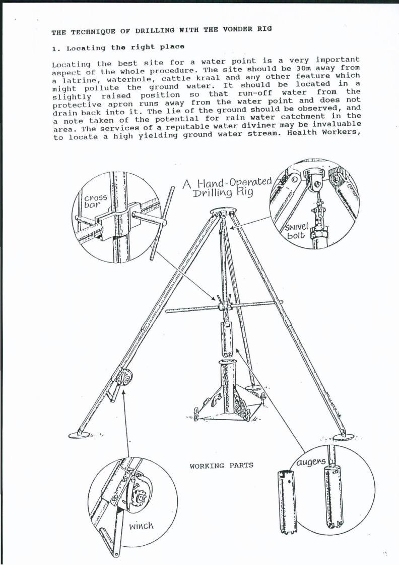
Locati ng the best site (or a water point is a very important aspec t or the whole procedure. The site should be 30m away from a latrine, waterhole, cattle kraal and any other feature which might pollute the ground water. It should be located in a slightly raised position so that run-off water from the protective apron runs away from the water point and does not drain back into it. The lie of the ground should be observed, and a note taken of the potential for rain water catchment in the area. The services of a reputable water diviner may be invaluable to locate a high yielding ground water stream. Health Workers,
WORKING PARTS
wil'lcl-\
.,

commuI1Lty leHders and local villagers should also be consulted, since they Hre the people who will use the water point.
2. setting up the rig
(1""" "" "''''''': ",Lt .. ha,. h"f!n located, it is important to set up the workti'lb 1 e exactly level. 11. plumb line is provided for this pllrpose. TIle plumb line is slung over the top of the work table bi'lrrel, and the centre of the plumb should come to rest on the edge o[ the flange of the barrel. The line of the plumb string is indicHted on tIle diagram of the rig. The plumb line is used on at least two sides of the worktable, thus ensuring that the table is laid exactly level.
The tri pod is then screwed together (the legs come in two sections and are colour labelled), and erected directly over the worktable. III order to get an exact position for the tripod, the steel ci'lble is lowered with the winch so that the stem linkage on the end of the cable raIls exactly centrally within the barrel of the worktable.
,'Ile position of the worktable and the tripod can be adjusted ,.llglltly by chiselling away soil with a shovel from underneath the work ti'lble or tripod respectively. The steel cable pulley and the threads for the drill stems should be oiled, and the worktable secured into position finally with the four steel pegs provided for the purpose.
3. The drilling operation
ThIs Is begun by attaching the crossbar to the first stem, so that it is about halfway down the stem. The stem is then attached to the stem linkage at the end of the steel cable. The cross bar and stem are then winched up and the auger attached throughout the bayonet adaptor. 1'he auger is then lowered through the barrel of the worktable and the two halves of the stem guide fitted over the studs at the top of the worktable. The auger is lowered further till it meets the ground, and the cross bar adjusted so that it lies about 300 mm above the guide. The actual drilling now commences.
The rig should be operated by at least 5 persons. One, more experienced operator, shOUld take charge of the winch, and be In overall charge of the rig. Four extra persons are required to turn the cross bar in a clockwise direction. II.s the cross bar is turned, pressure is exerted downwards. The cable supporting the stem is loosened with the winch, and this allows the stems and auger to move downwards, cutting into the soil beneath. In soft soils, the auger is able to penetrate about 400mm in 5 or 6 turns of the stem. The stem can be seen to move downwards as the auger penetrates the ground, but stops moving downwards when the auger is filled with soil.
At tllis stage the stem and auger are winched out of the ground. This entails taking off the stem guides from the top of the worktable, Hnd placing tllem temporarily on the pins fitted to the sides of the work table . 'rhe auger is raised so that it protrudes El I Igh t1 Y from the end 0 f the worktable. l\ steel rod, provided
.,

(
worl \ Wblc
POSITION TRIPOD ACCURATELY OVER WORKTABLE
~RT~DRK BY CDLLEEIl CDUSJIIS fROM EOUC~llDIIAL MATERIAL DEVELOPED BY MRS SUE L~VER
\
LEVEL THE WORKTABLE
sWivel bolt
OIL ALL WORKING PARTS

SlC II\
ATTTACH FIRST STEK TO SWIVEL BOLT
+., . -
uossbo.V'
FIT THE BAYONET ADAPTOR TO FIRST STEK
ougev-
/
ATTACH THE CROSSBAR TO THE FIRST STEK AND TIGHTEN
h~ boyoret adaptor
'iEoB~
INSERT THE AUGER BAR THROUGH THE HOLES IN THE AUGER , PLACE ON
THE WORKTABLE
auger-oar
R workWble

FIT STEM GUIDES AROUND STEM ON WORKTABLE
FIT THE BAYONET ADAPTOR TO AUGER
cr05sboV'
Q ):J
sto~9uides

THE CROSSBAR IS LOWERED INTO A CONVENIENT POSITION AND THE CROSSBAR BOLTS ARE TIGHTENED. THE CROSSBAR IS TURNED IN A CLOCKWISE DIRECTION TO DRILL.
REMOVE THE AUGER AFTER IT HAS BEEN FILLED WITH SOIL

with the rig, is now pushed through the holes in the upper end of the auger, and the bayonet fitting detached from the auger. The steel rod now holds the auger up inside the barrel of the worktable. 'l'he rod is used to remove the auger which is emptied by carefully knocking the open (upper) end on to a log of wood. In some cases the cuttings must be removed by rodding them out from the blade side of the auger.
Once emptied the rod if fitted back through the two holes in the top of the auger which is placed into the barrel of the worktable. The cable is then lowered and the bayonet adaptor attached to the auger. The auger is lowered and the stem guides refitted. 'l'he cross bar is retightened so that it lies about 300mm above the stem guide. The cable is loosened, and the cross bar turned once again in a clockwise direction. A further auger full of cuttings is drilled out, and raised to the surface. This process of drilling, bringing the cuttings to the surface and redrilling, is repeated. The winch is used to raise the stem and auger, and also to lower it back in position.
When one stems' depth has been drilled, a further stem is fitted, and the process is repeated. Obviously the more stems are used, the greater the time it takes to go through one drilling cycle. If conditions are right, the drilling cycle can be repeated until bedrock is met. If harder conditions are met, the normal auger is replaced by the hole saw, and the process repeated.
overooming Problems
Not all holes drilled by the rig are successful at first. In granite areas, it is possible that the auger may meet hard rock before it meets the water table. In this case it is best to change position and try again. In many cases a change in position of about 5 or 10 metres may enable the auger to penetrate much more deeply into the ground. The aim of course is to penetrate the ground as deeply as possible.
If possible at least 3 metres of water should be contained in the base of the drilling at the driest time of the year. 5 metres depth of water is much better. The aim should be as much water as possible Even 10 metres is not too much. Once the water table has been passed, drilling should always continue until bed rock is met. . In harder ground, it may be necessary for some people to sit on the cross bar to give the auger more "bite" and speed up the drilling process. One or two people on either side of the cross bar is enough. If the ground is too hard, and the rig is loaded with too many people, the cutters will either bend, wear out or break. The time has then come to try another site.
The drilling rig ·cannot cope with every situation. If bedrock lies in the ground above the level of the water table, only a big commercial drilling rig will be able to cope. It is important to establish the best areas in which the rig can operate. By going to these areas first, the drilling teams can gain their experience and confidence in easier ground. There is nothing like a few successful drillings to keep up the enthusiasm, not only of the drilling team but also the villagers who participate .
'. \0

Sometimes the auger is le [t a t the bottom of the hole if the stems are turned in an anti-clockwise direction by mistake. The auger c an be relocated fairly easily, by sending down the stems with the bayonet adaptor fitted, and carefully rotating the stems until the bayonet locks in position again on the auger.
Drilling holes through sand
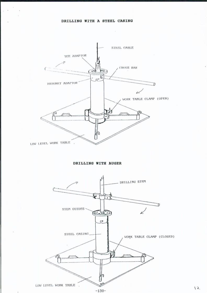
The problem of penetrating through mobile mud and sand formations has been overcome by a development of V & W Engineering in which a steel casing is allowed to penetrate the formation at the same time as the auger. 'l'he steel casing actually precedes the auger in this case. This additional piece of equipment includes a low work table. The work table is fitted with a clamp which secures a spec ial length of steel casing used to support the stem guides, when the normal auger is used. -The same work table also supports the specialised casing used to drill holes. When the steel casing itself i s used for drilling, the work table clamp is loosened, and an adaptor fitted to the top of the steel casing, which enables it to turn with a cross bar. The first steel casing is equ i pped with a cutt i ng edge similar to the hole saw. The sequence of drilling i s as follows.
The drilling procedure follows the normal pattern as with the standard rig, using the standard work table and augers as described in the previous section. This drilling procedure continues until a diff i cult formation like sand or loose mud is encountered. At this stage the standard work table is removed and the lower level work table is fitted in its place.
The standard auger and bayonet is also removed. A specialised bayonet adaptor is now fitted to the first steel casing which has a series of cutting teeth at its lower end for drilling. The swivel bolt attached to the steel cable is attached to the tee shaped adaptor which allows the cross bar to pass through it. This tee adaptor is lowered inside the bayonet and tee adaptor, and a cross bar passed through both the bayonet and tee adaptors. This enables the bayonet adaptor and the steel casings beaneath it to be turned. The sequence of drilling is as follows:
1 . Lower the swivel bolt into the bayonet adaptor 2. Pass the cross bar through the openings in the bayonet adaptor J. Attac h the first steel casing fitted with teeth to the bayonet 4. Use the winch to raise the casing and cross bar 5. Lower the casing through the worktable, and clamp tight 6. Fit more lengths of casing until the sand layer is met 7. Use the cross bar to turn the casings into the sand or mud B. Drill through the sand layer as far as possible 9. Clamp the casing IO.Remove cross bar and tee adaptor
Now t he cas i ng lies in the soft layer of sand or mud and the c ontents must be removed. Two methods can be used.
Flap Auger
I n the fi rst method, a specialised auger, narrow enough to fit
\ '
DRILLING WITH A STEEL CASING
(
.-LOIJ I.EVEI> WORK TIIBLE .
SH.EL CIIIlLE
Bill!
WOIIK TIIOLE CLIIMP (OPEN)
DRILLING WITH AUGER
-1.._-- 11111 LLl NG STF.M
STE11 GU 1 liES '
SlEEl. CIIS I Nr. _-+--IJOIlK TIIOLE CLIIMP (CLOSED)
I.OW LEVEL WOIIK ll\DLE .
-130-\:t.

'! "C' IIIII! ____ SW I VEL HOLT
U O • . , J '1:---.. - .. ~'''-j ]~ - -- - -, ---... _ .. --- f " ·--· r~;E ,;iJIIPTOR --'
IIOf,E IN UI\YONI;T l\iJl\l'TOII ~ I(m CllOSS fll\R
._--._:=0
1 -- fllIYONET IIDIIPTOR
_ _ STEEL CI\S I Nr.
~PE" J I\L I S W IIUGER W J TII NON IIEl UIIN FLI\!,
_ Ii"'
C: UTTEIIS
STEE l, CI\S I NG W ITII C;;UTTERS
SPECIALISED DRILLING EQUIPMENT FOR SAND
D SPECIALISED BAILER WITH STEEL NON-RETURN VALVE
- 131- \ ! "

within the steel casing and equipped with non-return flaps is lowered through the casing. 'l'his penetrates loose material, like mud, which passes through the flaps, but when pulled up, the flaps close off. Material like mud can be raised to the surface.
Bailing Technique
The following steps should be taken when excavating through sand using a bailer.
1. Winch operator slackens cable. 2. Bailer operator activates cable by a sudden pull which allows
the bailer to drop sharply. 3. This is repeated until the operator feels or hears that the
bailer has filled. The bailer gets heavier as it fills. 4. It is important that the hands are protected by gloves or a
piece of cardboard.
NOTE:
It is important that the sand is loosened first within the steel casing before the bailer can operate. This is best achieved by first loosening the sand with a small 125mm diameter auger which will pass down inside the stel casing. The sand will rise more easily into the bailer once it has been loosened.
Maintenance of the Drilling Rig
The rig should good service if kept clean and well oiled. Cleanliness is very important. When sterns are not used they should be stored on the stern rack. The threads of the sterns should be kept clean and oiled regularly. The tools should also be kept clean and the stern guides kept off the ground.
'l'he cable may begin to fray after months of use and the frayed section should be removed and a fresh section of the cable unwound from the winch and connected to the stern linkage.
The cutters also wear out, and require sharpening from time to time. They may also break under strain. V , W can resharpen and repair cutters and hole saws, but suggests that local engineering shops do the job. V , W supply new cutters with rivets, so that replacements can be made at the nearest workshop in the District. It is best to have spare sets of augers and hole saws.
Lining the drilled hole (normal soils)
Once the hole has been drilled to the greatest depth possible, and several metres of water have been found, it is important to line and protect the drilling as soon as possible and before the drilling collapses. If a successful drilling is anticipated, PVC casings should be immediately available to place down the hole. In addition a good gravel pack should also be available.
If a handpump is to be fitted, the casing size is normally 110mm and the lower 1.5m - 3m should be slotted with O.Bmm slots. Slotting is not required with the Bucket Pump.
\ '\

BALLING OPERATION
The following steps should be taken when excavating through s~nd ueing ~ bailer.
1. ~inch operator slackens cable 2. Bailer operator activ~tes cable by a sudden pull which allows
the bailer to drop sharply. . 3. This is repe~ted until the operator feels or hears that the
bailer has filled. The bailer gets heavier as it fills. 4. It is important that the h~nds are protected by gloves or a
piece of cardboard.
HOTE: It 1s important that the sand is loosened first within the steel casing before the bailer can operate. This is best achieved by first loosening the sand with a small 125mm diameter auger which will pass down inside the steel casing. The sand will rise more easily into the bailer once it has been loosened.
125D1111 AUGER
STEEL DART BAILER
-132-
CABLE
1 r
\ cLAMP MUS~ BE LOOSB TO ALLOW STEEL
CASING TO StNK DURING BAILING
/ ,"-

Il"fo,'p t-lIp ""sing is "c1de!] <It. le<lst one full auger full of granite chIps should be carefully added down the drilling to form a (oundation on which the casing can stand. Normally 3 metre Jengths of casing are lowered down the hole. 'rhe sections of casing should be PVC cemented together and held for one minute before lowering. The casings should be lowered until the entire tubewell is lined with a half metre of casing protruding above the ground.
The gravel pack is added into the annular space between the casing and the drilling. '1'his should be carefully chosen. Ideally special sand should be used, having a grain size between 1. Omm and 2.0mm. However sand of this size is not commonly available. It is best to seive out and thoroughly wash river sand from areas where it is common, and pack this sand in bags ready for use at the drilling site. The sand should have a large grain size of up to 6mm. 6mm granite chips can also be used. Builders sand and pit sand are unsuitable because they contain a high content of fine material whicll may silt up the tubewell and also slow down the flow of water from the aquifer into the casing. Some sands may even stop the flow of water. Very course river sand is the best and should always be carefully chosen and washed.
The gravel pack is added so that it fills the annular space to within at least one metre of the surface and preferably two metres. This final space is filled with a concrete mixture, well tamped down to form a good grout which seals off the gravel pack from the surface. The sanitary seal is important for the full protectuion of the tUbewell.
Every tubewell should not only be fitted with a suitable pump, but also built with a wide sanitary apron and water run-off channel, and a seepage area.
community participation
The one geat advantage of the hand operated drilling rig is that it makes full community participation possible at village level. There are many examples in Zimbabwe where the rig is operated fully under the control of villagers, which has an important influence on tile success of the final installation.
TEACHING NOTES
Hand drilling teChniques for tubewells are becoming more widely known in zimbabwe, but tllis impressive technique is little used in other countries in the sub-region. It has therefore been described in detail in these training notes.
A video film showing the technique should be shown as part of the course.