Embed Size (px)
DESCRIPTION
Cable & Wiring
Citation preview
-----------------Test Cable & WiringModule 12311
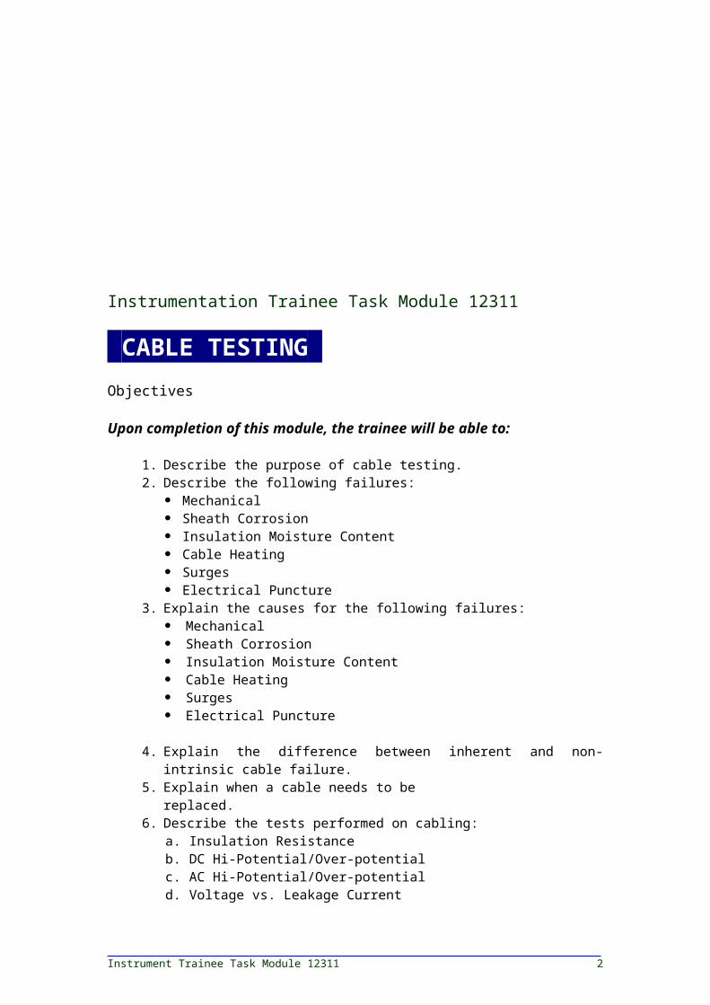
Instrumentation Trainee Task Module 12311
CABLE TESTING-Objectives
Upon completion of this module, the trainee will be able to:
1. Describe the purpose of cable testing. 2. Describe the following failures:
Mechanical Sheath Corrosion Insulation Moisture Content Cable Heating Surges Electrical Puncture
3. Explain the causes for the following failures: Mechanical Sheath Corrosion Insulation Moisture Content Cable Heating Surges Electrical Puncture
4. Explain the difference between inherent and non-intrinsic cable failure.
5. Explain when a cable needs to be replaced. 6. Describe the tests performed on cabling:
a. Insulation Resistanceb. DC Hi-Potential/Over-potentialc. AC Hi-Potential/Over-potentiald. Voltage vs. Leakage Currente. Go/No Go Hi-Potential/Over-Potential Test
7. Describe the operation of an analog volt-ohmmeter.
8. Describe the operation of a digital volt-ohmmeter.9. Describe the continuity test. 10.Describe the operation of a ground megger.
Prerequisites
Successful completion of the following Task Module(s) is required before beginning study of this Task Module: Instrumentation Level 3, Task Modules 12307 and 12316.
Required Trainee Material
1. Trainee Module2. Required Safety Equipment
COURSE MAP
Instrument Trainee Task Module 12311 2

This course map shows all of the Wheels of Learning task modules in the third level of the Instrumentation curricula. The suggested training order begins at the bottom and proceeds up. Skill levels increase as a trainee advances on the course map. The training order may be adjusted by the local Training Program Sponsor.
LEVEL 3 COMPLETE
Cable Testing — Module 12311 3
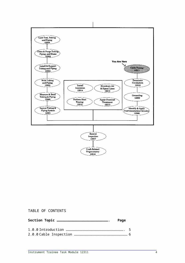
TABLE OF CONTENTS
Section Topic ………………………………………………………………….Page
1.0.0 Introduction …………………………………………………………………………. 52.0.0 Cable Inspection …………………………………………………………………… 63.0.0 Cable Failures and Their Analysis …………………………………………….
63.1.0 Mechanical Failures ……………………………………………………………….. 63.2.0 Sheath Corrosion …………………………………………………………………… 63.3.0 Surges ………………………………………………………………………………….. 73.4.0 Electrical Puncture …………………………………………………………………. 74.0.0 Inherent Causes of Cable Failure (Failure Due to Workmanship) …
84.1.0 Sheath Defects ………………………………………………………………………. 84.2.0 Insulation Defects ………………………………………………………………….. 84.3.0 Conductor Defects …………………………………………………………………. 95.0.0 Non-Intrinsic Causes of Cable Failure
(Environmental Cause of Cable Failure) …………………………………….9
5.1.0 Corrosion of Sheath ……………………………………………………………….. 95.2.0 Local Galvanic Action ……………………………………………………………… 95.3.0 Chemical Action …………………………………………………………………….. 95.4.0 External Fire and High Voltage Surges ………………………………………
95.5.0 Overheating ………………………………………………………………………….. 95.6.0 Mechanical Damage ……………………………………………………………….. 106.0.0 Cable Testing Procedures ……………………………………………………….. 107.0.0 Megohmmeter ……………………………………………………………………….. 118.0.0 Using the Megger …………………………………………………………………… 118.1.0 Checking the Instrument ………………………………………………………… 128.2.0 Checking the Test Leads …………………………………………………………. 138.3.0 Measuring Resistance …………………………………………………………….. 13
Instrument Trainee Task Module 12311 4
8.4.0 Interpretation of Reading ……………………………………………………….. 139.0.0 Megger Tests ………………………………………………………………………… 169.1.0 Short-Time Test …………………………………………………………………….. 169.2.0 Time-Resistance Method …………………………………………………………. 169.3.0 Dielectric Absorption Ratio ………………………………………………………. 1810.0.0Hi-Potential Tests …………………………………………………………………… 1810.1.0AC/DC Test …………………………………………………………………………….1810.2.0Voltage Versus Leakage Current Test (Step Voltage Test) …………..
1910.3.0Leakage Current Versus Time Test …………………………………………… 2010.4.0Go/No-Go Over-Potential Test ………………………………………………….
2110.5.0DC Over-Potential Test Connections and Procedures ………………….
2111.0.0AC Over-Potential Testing ……………………………………………………….. 2312.0.0Cable Replacement Criteria …………………………………………………….. 2412.1.0Corrective Action ……………………………………………………………………. 2413.0.0Ohmmeter …………………………………………………………………………….. 2413.1.0Series Resistance Measurement ………………………………………………. 2513.2.0Shunt Resistance Measurement ………………………………………………. 2513.3.0Ohms Adjust …………………………………………………………………………. 26
TABLE OF CONTENTS
Section Topic ………………………………………………………………….Page
14.0.0Analog Multimeter …………………………………………………………………. 2814.1.0General ………………………………………………………………………………… 2914.2.0General Specifications ……………………………………………………………. 2914.3.0Proper Use of Analog Meter …………………………………………………….
30
Cable Testing — Module 12311 5
14.4.0Measuring Resistance …………………………………………………………….. 3115.0.0Digital Meter Introduction ……………………………………………………….
3216.0.0Digital Meter Applications ……………………………………………………….. 3316.1.0Specifications ………………………………………………………………………… 3417.0.0Continuity Check ……………………………………………………………………. 3818.0.0Ground Megger ……………………………………………………………………… 3818.1.0Capability and Limitations ……………………………………………………….. 3818.2.0Operating Connections …………………………………………………………… 3918.3.0Single Rods and Small Grids ……………………………………………………. 4018.4.0Large Earth Electrode Systems or Large Area Ground Grids ………..
4118.5.0Operating Procedures …………………………………………………………….. 42
Trade Terms Introduced In This Module
Absorption test: With cable, it is a term applied to tests, such as the time-resistance test that is based on the absorption effect of good insulation compared to that of moist or contaminated insulation.
Cathodic protection: Protection applied to prevent electrolysis caused by a negative potential.
Corona: The field around a voltage of 1000 volts or higher that can be identified by a paleblue color and with the odor of ozone.
Dielectric Absorption Ratio: The ratio of two time-resistance readings, such as a 60second/30-second reading.
Ground megger: Measures ground resistance by applying a test current through the earth electrode under test.
Megger- General purpose measuring device that generates its own voltage and measures resistance as a function of current flow.
Polarization Index: The ratio of a 10-minute time-resistance reading to a 1-minute reading.
1.0.0 INTRODUCTION-
Cable testing is regarded as a preventive maintenance function used to minimize danger to personnel, avoid equipment damage, and prevent unexpected failure and downtime. Cable testing is conducted to chart the gradual deterioration over the years, to do acceptance testing after
Instrument Trainee Task Module 12311 6
installation, for verification of splices and joints, and for special repair testing.
2.0.0 CABLE INSPECTION-
Visual inspection can be made on energized cables, but if cables are to be touched or moved they should be de-energized. Cables in vaults, rooms, and at other locations should be inspected for the following on a yearly basis:
Physical damage, sharp bends, and excessive tension. Oil leaks, soft spots, and insulation swelling. Poor ground connections, metallic-sheath bonding deterioration,
corroded cable supports, and continuity of main grounding system. Cracked jackets of non-leaded cables. Damage to fireproofing. Tracking or corona. Soft spots in termination and splices. Potheads should be inspected for oil or compound leaks. Dirt and grime should be cleaned off and connections checked for
tightness.
Aerial cables should be inspected for mechanical damage caused vibration or deterioration of support and suspension system. Inspection should be made of cables for insulation abrasion and cable being bent or pinched.
3.0.0 CABLE FAILURES AND THEIR ANALYSIS
Cables can fail due to many reasons. Some of the major causes are discussed next.
3.1.0 MECHANICAL FAILURES
Mechanical failures can be due to breaks and defects of sheath material, mechanical punctures by people or machines, or cracks due to sharp bending or vibration. Whenever mechanical damage occurs in the cable sheath, the entrance of moisture will produce slow deterioration of insulation material, resulting in eventual failure of the cable. It is important therefore to take every precaution that either direct or indirect mechanical damage be eliminated or minimized by proper selection, installation, and maintenance of cable systems.
3.2.0 SHEATH CORROSION
Cause
Sheath corrosion can occur due to the following factors:
Dissimilar soil effects Galvanic action Acidity and alkali in conduits Chemical contamination in the soil
Cable Testing — Module 12311 7
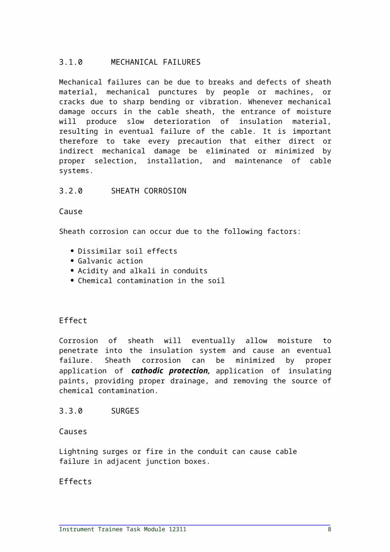
Effect
Corrosion of sheath will eventually allow moisture to penetrate into the insulation system and cause an eventual failure. Sheath corrosion can be minimized by proper application of cathodic protection, application of insulating paints, providing proper drainage, and removing the source of chemical contamination.
3.3.0 SURGES
Causes
Lightning surges or fire in the conduit can cause cable failure in adjacent junction boxes.
Effects
Surges can be indicated by the following:
Electrical Puncture Short Circuiting Cable Heating Insulation Failure Caole Fire
3.4.0 ELECTRICAL PUNCTURE
Cause
Once the insulation is weakened owing to any of the reasons already discussed, it may fail electrically. That is, the insulation system cannot confine the flow of electrical current to the conductor inside the insulation system. Failure may be phase to ground or phase to phase faults.
Effect
Obviously, if the failure is a short-circuit due to defective conductors, it will be detected by the circuit protective device. Some of the not so easy to detect electrical failures can be indicated by the following:
Bulging of the sheath Tree design marking Polymerized compound (wax) Lack of compound in the insulation
The cable failures can be further classified into two classes as follows: inherent causes, and non-intrinsic causes.
Instrument Trainee Task Module 12311 8
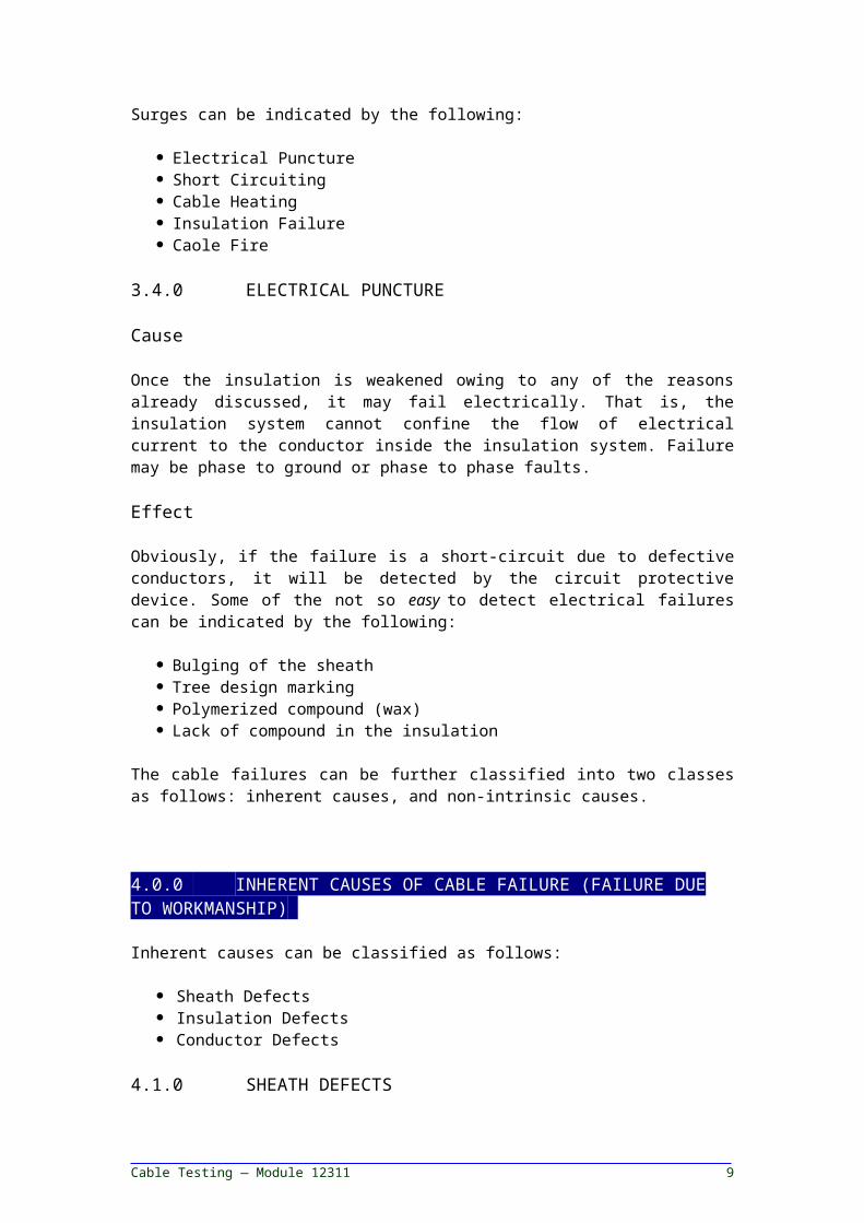
4.0.0 INHERENT CAUSES OF CABLE FAILURE (FAILURE DUE TO WORKMANSHIP)-
Inherent causes can be classified as follows:
Sheath Defects Insulation Defects Conductor Defects
4.1.0 SHEATH DEFECTS
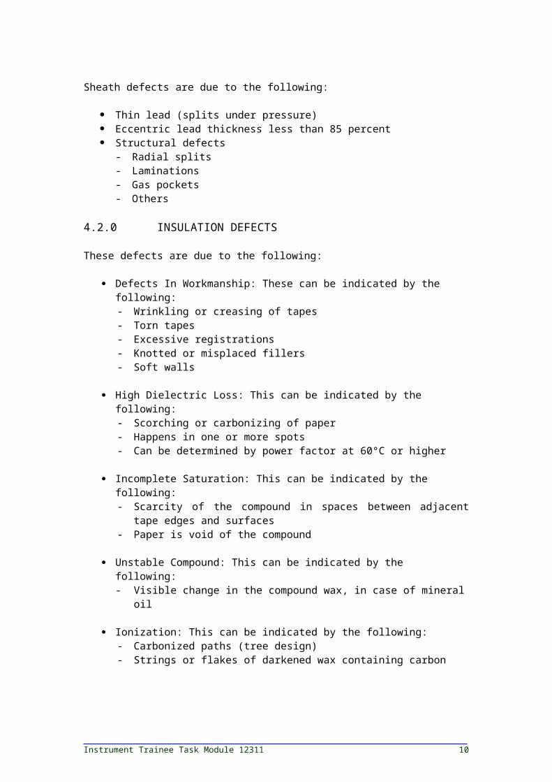
Sheath defects are due to the following:
Thin lead (splits under pressure) Eccentric lead thickness less than 85 percent Structural defects
- Radial splits- Laminations - Gas pockets - Others
4.2.0 INSULATION DEFECTS
These defects are due to the following:
Defects In Workmanship: These can be indicated by the following:- Wrinkling or creasing of tapes - Torn tapes- Excessive registrations - Knotted or misplaced fillers - Soft walls
High Dielectric Loss: This can be indicated by the following:- Scorching or carbonizing of paper- Happens in one or more spots- Can be determined by power factor at 60°C or higher
Incomplete Saturation: This can be indicated by the following:- Scarcity of the compound in spaces between adjacent tape
edges and surfaces - Paper is void of the compound
Unstable Compound: This can be indicated by the following: - Visible change in the compound wax, in case of mineral oil
Ionization: This can be indicated by the following:- Carbonized paths (tree design)- Strings or flakes of darkened wax containing carbon
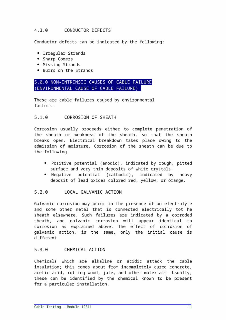
4.3.0 CONDUCTOR DEFECTS
Cable Testing — Module 12311 9
Conductor defects can be indicated by the following:
Irregular Strands Sharp Comers Missing Strands Burrs on the Strands
5.0.0 NON-INTRINSIC CAUSES OF CABLE FAILURE (ENVIRONMENTAL CAUSE OF CABLE FAILURE)-
These are cable failures caused by environmental factors.
5.1.0 CORROSION OF SHEATH
Corrosion usually proceeds either to complete penetration of the sheath or weakness of the sheath, so that the sheath breaks open. Electrical breakdown takes place owing to the admission of moisture. Corrosion of the sheath can be due to the following:
Positive potential (anodic), indicated by rough, pitted surface and very thin deposits of white crystals.
Negative potential (cathodic), indicated by heavy deposit of lead oxides colored red, yellow, or orange.
5.2.0 LOCAL GALVANIC ACTION
Galvanic corrosion may occur in the presence of an electrolyte and some other metal that is connected electrically tot he sheath elsewhere. Such failures are indicated by a corroded sheath, and galvanic corrosion will appear identical to corrosion as explained above. The effect of corrosion of galvanic action, is the same, only the initial cause is different.
5.3.0 CHEMICAL ACTION
Chemicals which are alkaline or acidic attack the cable insulation; this comes about from incompletely cured concrete, acetic acid, rotting wood, jute, and other materials. Usually, these can be identified by the chemical known to be present for a particular installation.
5.4.0 EXTERNAL FIRE AND HIGH VOLTAGE SURGES
These are due to fire in cable circuits and lightning strikes and surges.
5.5.0 OVERHEATING
This is mainly due to heating of a cable that is overloaded or external heat and high temperature.
5.6.0 MECHANICAL DAMAGE
Mechanical damage can be due to the following:
Instrument Trainee Task Module 12311 10
Vibration Expansion and Contraction External Causes Damage During Installation
6.0.0 CABLE TESTING PROCEDURES-
Cable testing is accomplished using a series of analytical tests. Normally, the maintenance tests performed on high and medium voltage cables are at a test voltage of 60 percent of final factory test voltage. When the exact construction of cable in an existing installation is not known, it is generally recommended that DC maintenance proof test voltage be based on rated AC circuit voltage using the recommended value for the smallest sized conductor in the rated AC voltage range. The DC voltage tests conducted on cables are insulation resistance measurement and DC high-potential test (DC hi-pot test). The DC hi-pot test can be performed as leakage current versus test voltage, leakage current versus time test, or go/no-go over-potential test.
It is always appropriate to conduct the insulation resistance measurement test first, and if data obtained looks good, then proceed with the DC over-potential test.
High insulation resistance values do not necessarily indicate high dielectric strength. Low insulation resistance values do not necessarily indicate low dielectric strength and potential equipment failure. Insulation that has been scuffed or physically damaged may have high insulation resistivity and low dielectric capability. A safe rule to observe is that insulation should have approximately one megohm of resistance for each 1000 volts of applied operating voltage with an absolute minimum insulation resistance of one megohm.
The insulation resistance is measured by a portable instrument consisting of a direct voltage source, such as a generator, battery, or rectifier, and a high-range ohmmeter that gives insulation resistance readings in megohms or ohms. This is a nondestructive method of determining the condition of the cable insulation to check contamination due to moisture, dirt, or carbonization. The insulation resistance measurement method does not give the measure of total dielectric strength of cable insulation or weak spots in the cable. Generally, the following voltages can be used for the indicated cables.
Voltage Rating of Cables Mevohmmeter VoltageUp to 300 V 500 V300 to 600 V 500 to 1,000 V2,400 to 5,000 V 2,500 V to 5 KVAbove 5,000 V Above 5 KV
7.0.0 MEGOHMMETER-
The megger is a general purpose, high resistance measuring device that generates its own voltage and measures resistance as a function of
Cable Testing — Module 12311 11
current flow. It must be used only on disconnected, de-energized pieces of equipment that have been verified dead, as stray voltages cause erroneous readings and may be hazardous to the user. The megger is useful in checking the insulation of cables, breakers, and other equipment. In case the output terminals are shorted together, the internal circuitry of the megger protects is from the damage.
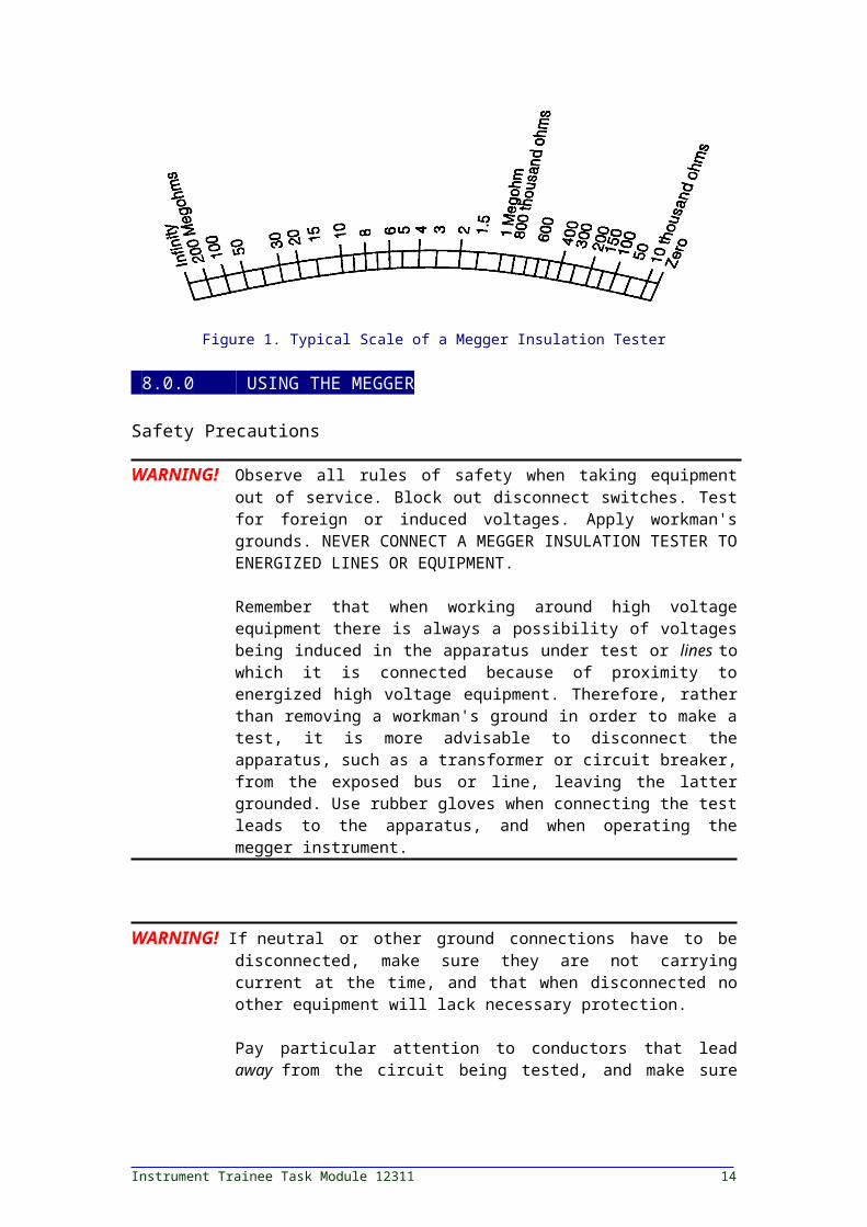
Figure 1 shows a typical scale for a megger insulation tester with a useful ohms range from 10,000 ohms to 200 megohms. An infinity reading on this scale indicates an insulation resistance in excess of 200 megohms. Similarly, a zero reading indicates a resistance of less than 10,000 ohms.
Figure 1. Typical Scale of a Megger Insulation Tester
8.0.0 USING THE MEGGER-
Safety Precautions
WARNING! Observe all rules of safety when taking equipment out of service. Block out disconnect switches. Test for foreign or induced voltages. Apply workman's grounds. NEVER CONNECT A MEGGER INSULATION TESTER TO ENERGIZED LINES OR EQUIPMENT.
Remember that when working around high voltage equipment there is always a possibility of voltages being induced in the apparatus under test or lines to which it is connected because of proximity to energized high voltage equipment. Therefore, rather than removing a workman's ground in order to make a test, it is more advisable to disconnect the apparatus, such as a transformer or circuit breaker, from the exposed bus or line, leaving the latter grounded. Use rubber gloves when connecting the test leads to the apparatus, and when operating the megger instrument.
WARNING! If neutral or other ground connections have to be disconnected, make sure they are not carrying current at the time, and that when disconnected no other equipment will lack necessary protection.
Instrument Trainee Task Module 12311 12
Pay particular attention to conductors that lead away from the circuit being tested, and make sure they have been properly disconnected from any source of voltage.
Observe the voltage rating of the megger instrument and regard it with appropriate caution. Large electrical equipment and cables usually have sufficient capacitance to store up a dangerous amount of energy from the test current. Make sure that this capacitance is discharged after the test and before handling the test leads.There is no fire hazard in the normal use of a Megger Insulation Tester. There is, however, a hazard when testing equipment located in inflammable or explosive atmospheres.
Slight sparking may be encountered: (1) when attaching the test leads to equipment in which the capacitance has not been completely discharged; (2) arcing through or over faulty insulation during a test; (3) discharge of capacitance following a test. Therefore, never use the megger in an explosive atmosphere.
Persons actually engaged in the test must stand clear of all parts of the complete high-voltage circuit unless the set is de-energized and all parts of the test circuit are grounded. Any person not directly associated with the work must be kept away from the test activities by suitable barriers, barricades, or warnings. To protect meters, always leave range switches in the highest position when the test set is not in use.
8.1.0 CHECKING THE INSTRUMENT
Place the instrument on a firm and fairly level base. Avoid strong magnetic fields. The pointer may appear to stand anywhere over the scale until the instrument is operated because the "megger" ohmmeter has no control springs. Visually inspect the megger; ensure that there is no obvious damage to the instrument.
If the instrument has a selector switch, set it to megohms divided by one. Then check infinity by turning the crank at normal speed in a clockwise direction (normal speed is indicated on the instrument). The pointer should move promptly to infinity. This check is made with no connections to the test terminals.
Then check zero by short-circuiting the testing terminals. Turn the crank slowly. The pointer should move promptly to zero.
8.2.0 CHECKING THE TEST LEADS
Always use well-insulated testing leads having single-conductor stranded wire. Before an actual measurement is made, check the testing leads. With leads connected to the megger terminals and with opposite ends separated, turn the crank at normal speed. If the pointer indicates less
Cable Testing — Module 12311 13
than infinity, there is a leak between the leads which must be removed before proceeding with tests. Touch together the test ends of the leads while turning the crank to make certain, by a zero reading, that the leads are not open-circuited.
8.3.0 MEASURING RESISTANCE
After the instrument and test leads have been connected, connect the testing leads to apparatus to be tested. For testing to ground, connect from the line terminal to a conductor of the apparatus and from the earth terminal to the machine frame, or sheath of cable, for a good ground. For testing between two conductors, connect test leads to the two conductors.
Turn the crank in a clockwise direction at normal speed, which is indicated on the instrument. Observe the position of pointer over the scale; it shows the value of insulation resistance of the equipment under test. Take the reading after operating the megger for a fixed time period, preferably 30 to 60 seconds.
A very important consideration in making insulation resistance tests is the time required for the reading of insulation resistance to reach a maximum. The time required to establish a partial charge in the equipment under test is very short, usually no more than a few seconds. However, the dielectric absorption effect causes further delay in reaching full "charge". It may be a matter of minutes or even hours for this electrification time to be completed and for the pointer to reach an absolute maximum.
8.4.0 INTERPRETATION OF READING
You should consider readings of insulation resistance as relative. They can be quite different for one cable tested three days in a row, yet not mean bad insulation. What really matters is the trend in readings over a time period, showing lessening resistance and warnings of coming problems. Periodic testing is, therefore, your best approach to preventive maintenance. You should make these periodic tests in the same way each time, i.e., with the same test connections and with the same test voltage applied for the same length of time.
Also, you should make tests at about the same temperature, or correct them to the same temperature.
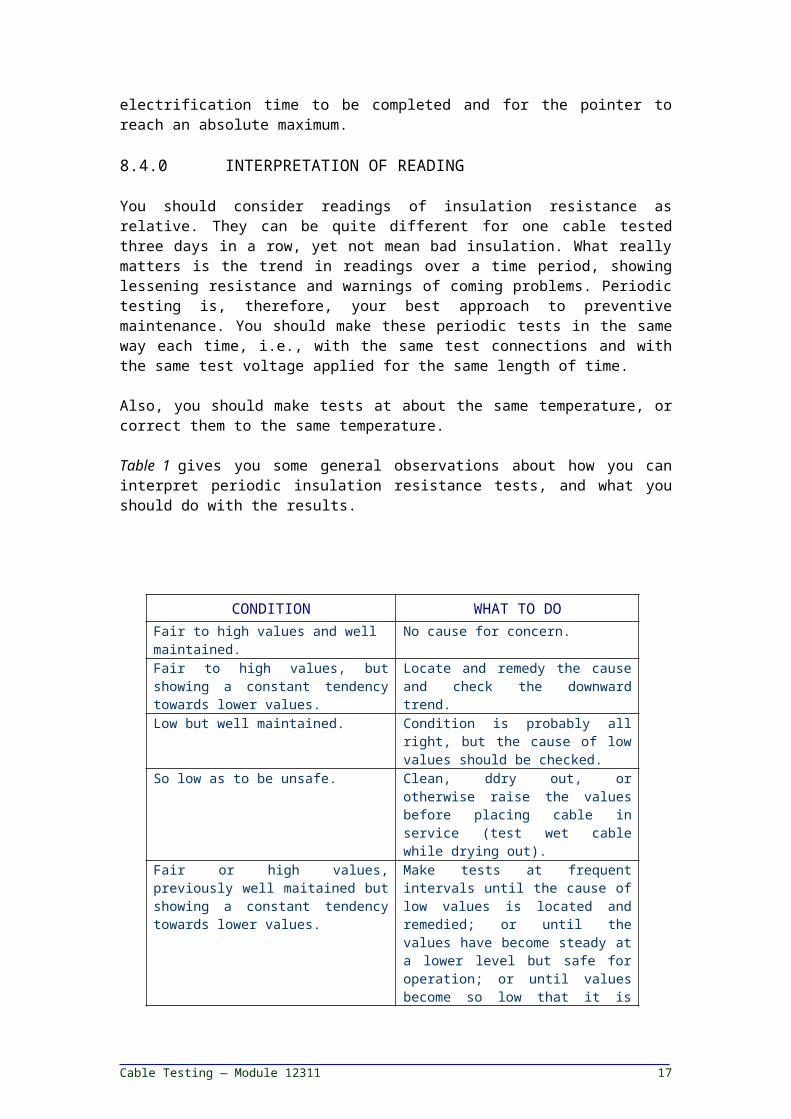
Table 1 gives you some general observations about how you can interpret periodic insulation resistance tests, and what you should do with the results.
CONDITION WHAT TO DOFair to high values and well maintained.
No cause for concern.
Fair to high values, but showing a constant tendency towards lower values.
Locate and remedy the cause and check the downward trend.
Instrument Trainee Task Module 12311 14
Low but well maintained. Condition is probably all right, but the cause of low values should be checked.
So low as to be unsafe. Clean, ddry out, or otherwise raise the values before placing cable in service (test wet cable while drying out).
Fair or high values, previously well maitained but showing a constant tendency towards lower values.
Make tests at frequent intervals until the cause of low values is located and remedied; or until the values have become steady at a lower level but safe for operation; or until values become so low that it is unsafe to keep the cable in operation.
Table 1. Interpretation of Insulation Resistance Tests
The following is the general procedure when using a megohmmeter for resistance measurement tests.
NOTE: Ensure circuits to be meggered are locked/tagged out per local procedures.
Disconnect the cable to be tested from other equipment and circuits to ensure that it is not energized.
Discharge all stored capacitance in the cable by grounding it before testing, as well as after completing tests.
Connect the line terminal of the instrument to the conductor to be tested.
Ground all other conductors together to sheath and to ground. Connect these to the earth terminal of the test set.
Similarly measure other insulation resistance values between one conductor and all other conductors connected, one conductor to ground, and so on. The connections are shown in Figure 2.
The guard terminal of the megohmmeter can be used to eliminate the effects of surface leakage across exposed insulation at the test end of the cable, or both ends of the cable, or leakage to ground.
Cable Testing — Module 12311 15
Figure 2. Cable Test Connections for Insulation Resistance Measurement
The insulation resistance measurements should be conducted at regular intervals and records kept for comparison purposes. Keep in mind that, for valid comparison, the readings must be corrected to a base temperature,
Instrument Trainee Task Module 12311 16
such as 20°C. A continued downward trend is an indication of insulation deterioration even though the resistance values measured are above minimum acceptable limits.
9.0.0 MEGGER TESTS-
In general, all megger tests are used to determine some value or ratio of insulation resistance. We will discuss various types of megger tests that are used to test high and medium voltage cables.
9.1.0 SHORT-TIME TEST
In the short-time test, the megger is connected across the insulation to be tested and operated for a short period of time. Sixty seconds is usually recommended but sometimes thirty seconds is used. The short time test is sometimes called a spot test and is recommended for comparison with previous records.
If a hand-cranked megohmmeter is used, the reading should be taken while still cranking at rated speed. Readings should be taken at the end of the 30 or 60 second period, even though the pointer is still climbing. Then, if all future tests are made using the same time, a good comparison of the trend of the insulation can be made.
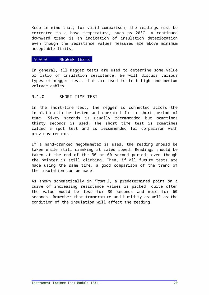
As shown schematically in Figure 3, a predetermined point on a curve of increasing resistance values is picked, quite often the value would be less for 30 seconds and more for 60 seconds. Remember that temperature and humidity as well as the condition of the insulation will affect the reading.
Figure 3. Resistance vs. Time
9.2.0 TIME-RESISTANCE METHOD
This method is fairly independent of temperature and often can give conclusive information without records of past tests. It is based on the absorption effect of good insulation compared to that of moist or
Cable Testing — Module 12311 17
contaminated insulation, and is performed by taking successive readings at specific times and noting the differences in readings. See curves in Figure 4. Tests by this method are sometimes referred to as absorption tests.
Figure 4. Typical Curves Showing Dielectric Absorption Effect in a 'Time- Resistance" Test
Note that good insulation shows a continual increase in resistance (less current-see Curve A) over a period of time (in the order of 5 to 10 minutes). This is caused by the absorption current discussed above; good insulation shows this charge effect over a time period much longer than the time required to charge the capacitance of the insulation.
If the insulation contains much moisture or contaminants, the absorption effect is masked by a high leakage current which stays at a fairly constant value, keeping the resistance reading low (remember: R = E/I).
Figure 5 shows a 60-second test for good and bad insulation. When the insulation is in good shape, the 60-second reading is higher than the 30-second reading.
A further advantage of the "double-reading" test, is that it gives a clearer picture, even when a "spot reading" indicates that the insulation looks fine.
Instrument Trainee Task Module 12311 18

Figure 5. Typical Card Plot of a Time-Resistance or Double-Reading Test
9.3.0 DIELECTRIC ABSORPTION RATIO
The ratio of two time-resistance readings (such as a 60-second reading divided by a 30-second reading) is called a Dielectric Absorption Ratio. It is useful in recording information about insulation. If the ratio is a 10-minute reading divided by a 1-minute reading, the value is called the Polarization Index.
With hand-cranked megger instruments, it is easier to run the test for only 60 seconds, taking the first reading at 30 seconds. If a power-operated megger instrument is used, the results of running the test for a full 10 minutes, taking reading at 1 and 10 minutes will give the polarization index. Refer to manufacturer's information for standard readings that can be expected on the cable being tested.
10.0.0 HI-POTENTIAL TESTS-
Various tests on cable can be accomplished using a DC high potential test set. The following will identify specific tests with their procedures.
10.1.0 AC/DC TEST
WARNING! Do not use high voltage test sets on low voltage cables.
This test is extensively used for acceptance and maintenance of cables. It can indicate the relative condition of the insulation at voltages above or near operating levels. This test can be used for identification of weakness in the cable insulation and can also be used to break down an incipient fault. Generally, it is not recommended that this test be used for breakdown of incipient faults even though some test operators use it for this purpose. Therefore, the incipient fault breakdown probability should be anticipated before and during the hi-pot test. The impending cable failure will usually be indicated by sudden changes in the leakage current,
Cable Testing — Module 12311 19
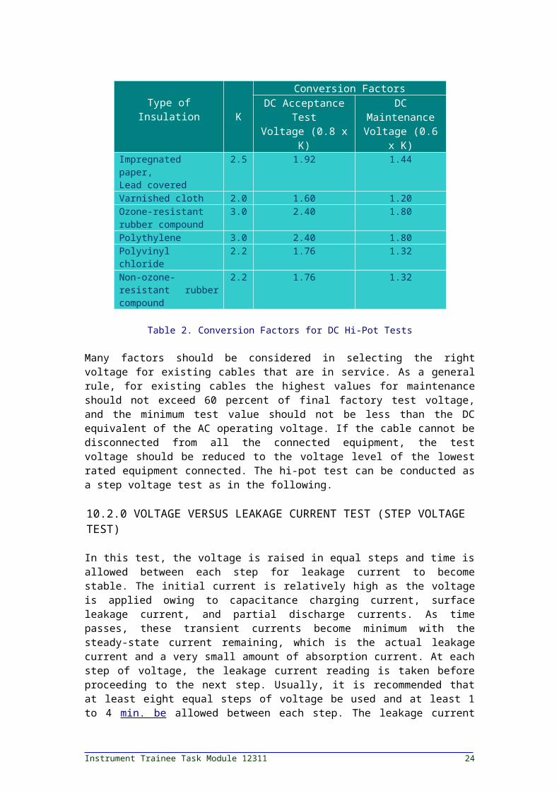
and before insulation is damaged the test can be stopped. The test voltage values for DC hi-pot tests are based upon final factory test voltage, which is determined by the type and thickness of insulation, the size of conductors, the construction of cable, and applicable industry standards. The DC test values corresponding to AC factory proof test voltages specified by the industry standards are usually expressed in terms of the ratio of DC to AC voltage from each insulation system. This ratio is designated as K which when multiplied by the acceptance test factor of 80 percent and maintenance factor of 60 percent yields the conversion factors to obtain the DC test voltages for hi-pot tests. These recommended test voltage conversion factors are shown in Table 2.
Type ofInsulation K
Conversion FactorsDC Acceptance
TestVoltage (0.8 x K)
DC MaintenanceVoltage (0.6 x
K)Impregnated paper,Lead covered
2.5 1.92 1.44
Varnished cloth 2.0 1.60 1.20Ozone-resistant rubber compound
3.0 2.40 1.80
Polythylene 3.0 2.40 1.80Polyvinyl chloride 2.2 1.76 1.32Non-ozone-resistant rubber compound
2.2 1.76 1.32
Table 2. Conversion Factors for DC Hi-Pot Tests
Many factors should be considered in selecting the right voltage for existing cables that are in service. As a general rule, for existing cables the highest values for maintenance should not exceed 60 percent of final factory test voltage, and the minimum test value should not be less than the DC equivalent of the AC operating voltage. If the cable cannot be disconnected from all the connected equipment, the test voltage should be reduced to the voltage level of the lowest rated equipment connected. The hi-pot test can be conducted as a step voltage test as in the following.
10.2.0 VOLTAGE VERSUS LEAKAGE CURRENT TEST (STEP VOLTAGE TEST)
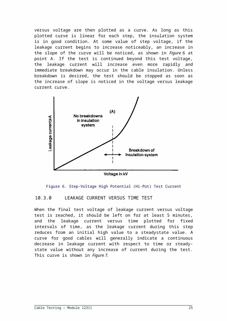
In this test, the voltage is raised in equal steps and time is allowed between each step for leakage current to become stable. The initial current is relatively high as the voltage is applied owing to capacitance charging current, surface leakage current, and partial discharge currents. As time passes, these transient currents become minimum with the steady-state current remaining, which is the actual leakage current and a very small amount of absorption current. At each step of voltage, the leakage current reading is taken before proceeding to the next step. Usually, it is recommended that at least eight equal steps of voltage be used and at least 1 to 4 min. be allowed between each step. The leakage current versus voltage are then plotted as a curve. As long as this plotted curve is linear for each step, the insulation system is in good condition. At some value of step voltage, if the leakage current begins to increase
Instrument Trainee Task Module 12311 20

noticeably, an increase in the slope of the curve will be noticed, as shown in Figure 6 at point A. If the test is continued beyond this test voltage, the leakage current will increase even more rapidly and immediate breakdown may occur in the cable insulation. Unless breakdown is desired, the test should be stopped as soon as the increase of slope is noticed in the voltage versus leakage current curve.
Figure 6. Step-Voltage High Potential (Hi-Pot) Test Current
10.3.0 LEAKAGE CURRENT VERSUS TIME TEST
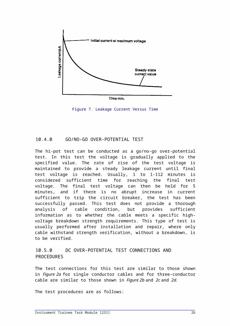
When the final test voltage of leakage current versus voltage test is reached, it should be left on for at least 5 minutes, and the leakage current versus time plotted for fixed intervals of time, as the leakage current during this step reduces from an initial high value to a steadystate value. A curve for good cables will generally indicate a continuous decrease in leakage current with respect to time or steady-state value without any increase of current during the test. This curve is shown in Figure 7.
Figure 7. Leakage Current Versus Time
Cable Testing — Module 12311 21

10.4.0 GO/NO-GO OVER-POTENTIAL TEST
The hi-pot test can be conducted as a go/no-go over-potential test. In this test the voltage is gradually applied to the specified value. The rate of rise of the test voltage is maintained to provide a steady leakage current until final test voltage is reached. Usually, 1 to 1-112 minutes is considered sufficient time for reaching the final test voltage. The final test voltage can then be held for 5 minutes, and if there is no abrupt increase in current sufficient to trip the circuit breaker, the test has been successfully passed. This test does not provide a thorough analysis of cable condition, but provides sufficient information as to whether the cable meets a specific high-voltage breakdown strength requirements. This type of test is usually performed after installation and repair, where only cable withstand strength verification, without a breakdown, is to be verified.
10.5.0 DC OVER-POTENTIAL TEST CONNECTIONS AND PROCEDURES
The test connections for this test are similar to those shown in Figure 2a for single conductor cables and for three-conductor cable are similar to those shown in Figure 2b and 2c and 2d.
The test procedures are as follows:
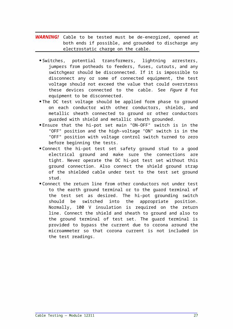
WARNING! Cable to be tested must be de-energized, opened at both ends if possible, and grounded to discharge any electrostatic charge on the cable.
Switches, potential transformers, lightning arresters, jumpers from potheads to feeders, fuses, cutouts, and any switchgear should be disconnected. If it is impossible to disconnect any or some of connected equipment, the test voltage should not exceed the value that could overstress these devices connected to the cable. See Figure 8 for equipment to be disconnected.
The DC test voltage should be applied form phase to ground on each conductor with other conductors, shields, and metallic sheath connected to ground or other conductors guarded with shield and metallic sheath grounded.
Ensure that the hi-pot set main "ON-OFF" switch is in the "OFF" position and the high-voltage "ON" switch is in the "OFF" position with voltage control switch turned to zero before beginning the tests.
Connect the hi-pot test set safety ground stud to a good electrical ground and make sure the connections are tight. Never operate the DC hi-pot test set without this ground connection. Also connect the shield ground strap of the shielded cable under test to the test set ground stud.
Connect the return line from other conductors not under test to the earth ground terminal or to the guard terminal of the test set as desired. The hi-pot grounding switch should be switched into the
Instrument Trainee Task Module 12311 22
appropriate position. Normally, 100 V insulation is required on the return line. Connect the shield and sheath to ground and also to the ground terminal of test set. The guard terminal is provided to bypass the current due to corona around the microammeter so that corona current is not included in the test readings.
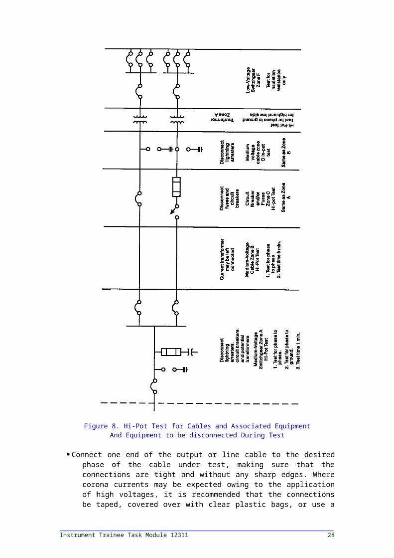
Figure 8. Hi-Pot Test for Cables and Associated EquipmentAnd Equipment to be disconnected During Test
Cable Testing — Module 12311 23
Connect one end of the output or line cable to the desired phase of the cable under test, making sure that the connections are tight and without any sharp edges. Where corona currents may be expected owing to the application of high voltages, it is recommended that the connections be taped, covered over with clear plastic bags, or use a corona ring or corona shield. The other end of the output or line cable is connected to the output or line stud of the test set.
The cable used for connecting the hi-pot test set to the cable under test, that is, the line or output cable, should be short and direct and supported along its length so that it is not touching the ground or grounding materials or surfaces. If extension cables are to be used with the output or line cable to reach the cable under test, shielded cable should preferably be used for this purpose. The shields of the extensionable and hi-pot cable should be connected with a shield jumper, which should be run away from the splice to prevent leakage. In case of the extension cable being non-shielded, care should be taken to keep the non-shielded wire away from the grounding surfaces as explained previously.
When shielded cable is being tested, it is recommended that the shield be trimmed back about 1 inch for every 10 KV. The shield on the test set end of the cable is connected to the ground as explained previously. The shield on the other end of cable can be taped and left hanging without any connections made to it.
The test set now should be plugged into a 115 V, 60 Hz outlet. It is important that the AC supply voltage have good line regulation, because the DC output voltage of the test set depends upon the AC line input voltage. The test
voltage kilovolt range should be selected before beginning the test. The power now can be turned on and the test begun either as step-voltage or as a go/nogo test.
After the test is completed, turn the high-voltage switch of the test set to "OFF". Allow the cable just tested to discharge either through the internal test set discharge circuit or external ground applied to the cable by means of hot stick or gloves.
WARNING! Do not touch the cable until it is fully discharged.
Connect a ground to the cable that was tested and leave it connected for at least twice the length of the test time or until the cable is connected into the system.
11.0.0 AC OVER-POTENTIAL TESTING-
Cables and accessories may be field tested with AC voltage, although this is normally not done. The most common field test on cables involves DC voltage tests. However, AC highpotential acceptance and maintenance tests may be conducted on cables and cable accessories. Before a successful test can be carried out the AC test set should have adequate volt-ampere capacity to supply the required cable charging current requirement. The VA capacity of the test set may be determined by the formula:
VA = 2fCE2 or kVA = 2fCE2103
Instrument Trainee Task Module 12311 24
where: C is capacitance in microfarad per milef is the frequency in hertzE is the test voltage in kilovolts of the test set
The test voltage values recommended for acceptance and maintenance tests are 80 and 60 percent, respectively, of the final factory test voltage. The test connections are similar to the test connections indicated in Figure 2 for DC testing of cables.
The power factor test may also be conducted for cables and accessories. The power factor for each conductor with respect to ground should be made. The evaluation should be based upon comparative analysis with previous test results or correlated with test results of similar types of cables.
12.0.0 CABLE REPLACEMENT CRITERIA-
The following information is meant to serve as a general guide for typical test values. Decisions regarding corrective action should be made by the engineering staff.
12.1.0 CORRECTIVE ACTION
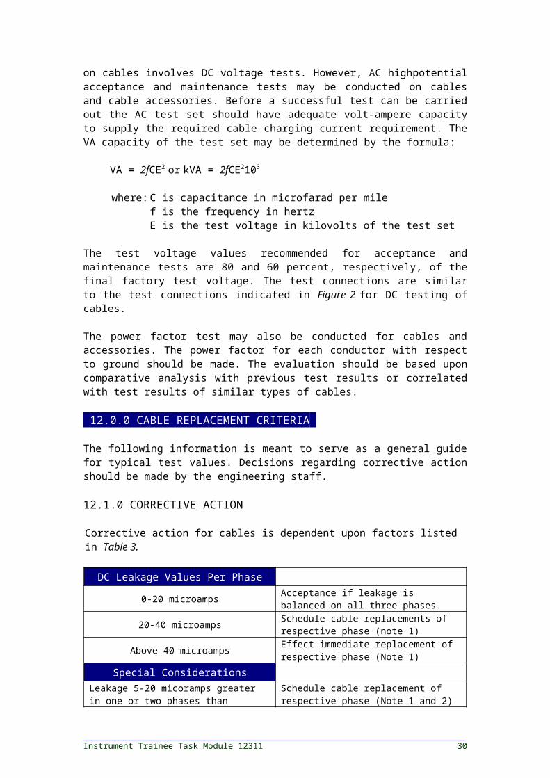
Corrective action for cables is dependent upon factors listed in Table 3.
DC Leakage Values Per Phase
0-20 microamps Acceptance if leakage is balanced on all three phases.
20-40 microamps Schedule cable replacements of respective phase (note 1)
Above 40 microamps Effect immediate replacement of respective phase (Note 1)
Special ConsiderationsLeakage 5-20 micoramps greater in one or two phases than remaining acceptable phase
Schedule cable replacement of respective phase (Note 1 and 2)
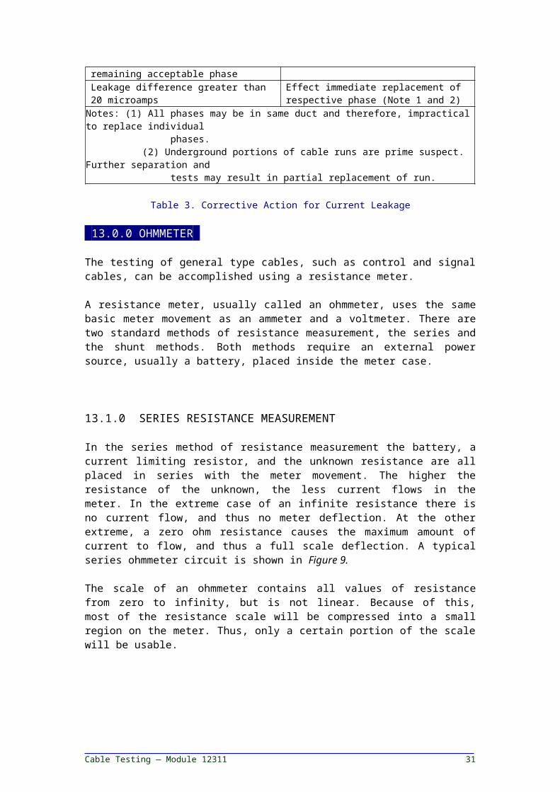
Leakage difference greater than 20 microamps
Effect immediate replacement of respective phase (Note 1 and 2)
Notes: (1) All phases may be in same duct and therefore, impractical to replace individual phases. (2) Underground portions of cable runs are prime suspect. Further separation and tests may result in partial replacement of run.
Table 3. Corrective Action for Current Leakage
13.0.0 OHMMETER-
The testing of general type cables, such as control and signal cables, can be accomplished using a resistance meter.
A resistance meter, usually called an ohmmeter, uses the same basic meter movement as an ammeter and a voltmeter. There are two standard
Cable Testing — Module 12311 25
methods of resistance measurement, the series and the shunt methods. Both methods require an external power source, usually a battery, placed inside the meter case.
13.1.0 SERIES RESISTANCE MEASUREMENT
In the series method of resistance measurement the battery, a current limiting resistor, and the unknown resistance are all placed in series with the meter movement. The higher the resistance of the unknown, the less current flows in the meter. In the extreme case of an infinite resistance there is no current flow, and thus no meter deflection. At the other extreme, a zero ohm resistance causes the maximum amount of current to flow, and thus a full scale deflection. A typical series ohmmeter circuit is shown in Figure 9.
The scale of an ohmmeter contains all values of resistance from zero to infinity, but is not linear. Because of this, most of the resistance scale will be compressed into a small region on the meter. Thus, only a certain portion of the scale will be usable.
Figure 9. Series Ohmmeter
The ohmmeter can be modified to make it more sensitive to lower values of resistance by decreasing the current limiting resistor. This would mean that smaller unknown resistances would be a larger fraction of the total resistance. In order to be able to reduce the current limiting resistor and not exceed the maximum allowable current through the movement, it is necessary to either decrease the battery voltage or increase the full scale current of the meter (with a shunt resistor, for example). Practical considerations prevent using very large full scale meter movements. Higher current requires that a greater amount of power be dissipated. Unless the unknown resistor was rated for this power, it would quickly bum out. In addition, the battery would have to be much larger and heavier than conventional flashlight batteries to be able to supply the tens or hundred of milliamperes required by still larger meter movements.
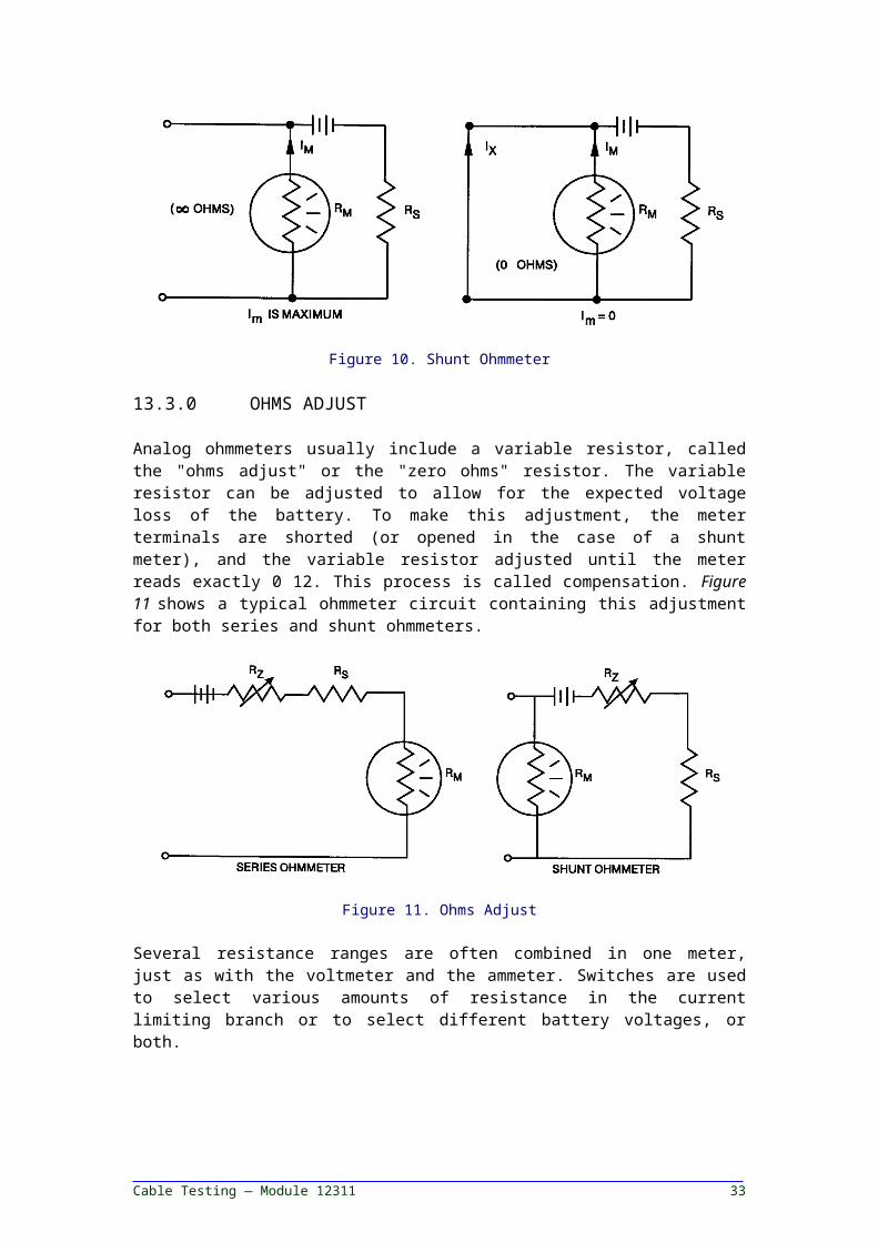
13.2.0 SHUNT RESISTANCE MEASUREMENT
Instrument Trainee Task Module 12311 26
Because of the problems already mentioned, the series ohmmeter is not usually used for low resistance measurements. Instead, the shunt ohmmeter is used. In the shunt method of resistance measurements, there is again a battery in series with a current limiting resistor and the meter movement. This means that the unknown resistance is in parallel to the meter movement. A typical shunt ohmmeter circuit is shown in Figure 10.With the shunt ohmmeter, resistances can be measured which are the same order of magnitude as the meter resistance. With the series ohmmeter, the unknown resistance must be of the same order of magnitude as the current limiting resistor.
Figure 10. Shunt Ohmmeter
13.3.0 OHMS ADJUST
Analog ohmmeters usually include a variable resistor, called the "ohms adjust" or the "zero ohms" resistor. The variable resistor can be adjusted to allow for the expected voltage loss of the battery. To make this adjustment, the meter terminals are shorted (or opened in the case of a shunt meter), and the variable resistor adjusted until the meter reads exactly 0 12. This process is called compensation. Figure 11 shows a typical ohmmeter circuit containing this adjustment for both series and shunt ohmmeters.
Figure 11. Ohms Adjust
Several resistance ranges are often combined in one meter, just as with the voltmeter and the ammeter. Switches are used to select various
Cable Testing — Module 12311 27
amounts of resistance in the current limiting branch or to select different battery voltages, or both.
Safety Precautions
WARNING! If possible do not work alone when making measurements of circuits where a shock hazard can exist. At the very minimum, notify another person that you are, or intend to make such measurements. This is simply good common sense.
If you were to get shocked and no one knew you were making these measurements, you might not receive help in time.
Locate all voltage sources and accessible paths prior to making measurement connections. Check that the test equipment is properly grounded and the right rating and type of fuse(s) is installed. Set the instrument to the proper range before power is applied.
The easiest way to get shocked is to go into a circuit you thought was de-energized only to find out it was not completely de-energized.
An ungrounded piece of equipment can have a "common line" which can be hundreds of volts above real ground. This can present a shock potential.
A correct fuse can save your life. If the circuit draws .25 amp and the fuse is rated at .5 amp and you get shocked, it is possible the fuse will blow before you get seriously hurt. If by mistake a 1 amp fuse is installed the fuse will "never blow", even when it should.
Changing meters ranges when power is applied can pose two problems: arcs across the switch contacts damaging the contacts; arcs through the switch to the switch handle, and through you if the voltages are high enough.
Remember, voltages may appear unexpectedly in defective equipment. An open bleeder resistor may result in a capacitor retaining a dangerous charge. Turnoff power and discharge all capacitors before connecting or disconnecting tests leads to and from the circuit being measured.
Test a meter on a live circuit before using to ensure proper operation.
Instrument Trainee Task Module 12311 28

If a circuit is defective, you cannot reasonably assume what the voltages and current formed in the circuit will be.
For your own safety, inspect the test leads for cracks, breaks, or cracks in the insulation, prods, and connectors before each use. If any defects exist, replace the test leads immediately.
WARNING! Do not make measurements in a circuit where corona is present. Corona can be identified by a pale-blue color emanating from sharp metal points in the circuit, the odor of ozone, and its sound.
Corona is the field around a voltage of 1000 V or higher, and is caused by the breaking down of the air molecules.
If a corona exists, the voltage is too high to measure with a multimeter.
Hands, shoes, floor, and workbench must be dry. Avoid making measurements under humid, damp, or other environmental conditions that could affect the dielectric withstanding voltage of the test leads or instrument.
In the unlikely event of a shock, how much current the shock victim receives from the voltage source is related to the resistance between the circuit and ground.
The drier the person is the more resistant he is.
Damp, humid, and hot environments decrease the insulating abilities of the meter leads, thereby, increasing the probability of their breakdown.
Use extreme caution when making measurements in an RF circuit where a dangerous combination of voltages could be present, such as in a modulated RF amplifier.
Do not make measurements using test leads which differ from those originally furnished with the instrument.
Do not come into contact with any object which could provide a current path to the common side of the circuit under test or power line ground. Always stand on a dry insulating surface capable of withstanding the voltage being measured or that could be encountered.
The range or function switch should be changed only when the power to the circuit under measurement is turned off. This will provide maximum safety to the user and eliminate arcing the switch contacts.
4.0.0 ANALOG MULTIMETER-
Cable Testing — Module 12311 29
One of the most common multiple function meters used today is the volt-ohm multimeter (VOM). There are many different models of the basic multimeter. Although each is slightly different in detail, all are generally similar. To prevent having to explain each and every meter, a common multimeter will be explained here. Any controls or functions on your meter not covered here should be reviewed in the applicable technical manual.
14.1.0 GENERAL
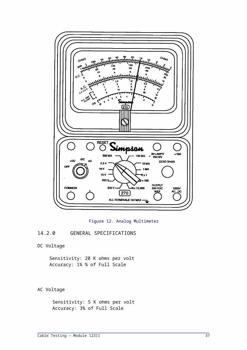
The volt-ohm multimeter (VOM) is a rugged, accurate, compact, easy-to-use instrument. The instrument can be used to make accurate measurements of DC and AC voltage, direct current, resistance, decibels and "Output Voltage." An analog meter is shown in Figure 12.
Figure 12. Analog Multimeter
14.2.0 GENERAL SPECIFICATIONS
DC Voltage
Instrument Trainee Task Module 12311 30
Sensitivity: 20 K ohms per volt Accuracy: 1¾ % of Full Scale
AC Voltage
Sensitivity: 5 K ohms per volt Accuracy: 3% of Full Scale
DC Current
250 mV to 400 mV drop Accuracy: 1¾% of Full Scale
Resistance
Accuracy: 1.75° of arcNominal open circuit voltage 1.5 V
NOTE: 9 V on the 10K ohm rangeNominal short circuit current
1 ohm range 1.25 mA 100 ohm range 1.25 mA10 K ohm range 75 microamps
Meter Frequency Response
Up to 100 KHz
14.3.0 PROPER USE OF ANALOG METER
A fuse can be provided to protect the circuits on the ohmmeter ranges and from excessive overloads on the milliampere ranges. If instrument fails to indicate, the fuse may be burned out.
In addition to the fuse, a varistor can protect the indicating instrument circuit. The varistor limits the current through the moving coil in case of overload.
The fuse and varistor will prevent serious damage to the meter in most cases of accidental overload. However, no overload protection system is completely foolproof and misapplication on high voltage circuits can damage the instrument. Care and caution should always be exercised to protect both you and your VOM.
In addition to the actual steps used in making a measurement there are some other points to consider while using the multimeter. They are listed on the following pages.
1. Keep the instrument in a horizontal position when storing it and away from the edge of a workbench, shelf or other areas where it may be knocked off and damaged.
Cable Testing — Module 12311 31

The multimeter is much more stable when laying horizontally. By laying it down the chance of meter damage is minimized. If the meter is stored or placed near the edge of a shelf, the chances of meter damage will increase.
2. Avoid rapid or extreme temperature changes.
The life and accuracy are both affected by the aging of the meter components.
Rapid and extreme temperature changes will advance the aging of those components.
3. Avoid overloading the measuring circuits of the instrument. Develop a habit of checking the range position before connecting the test leads to a circuit.
Even slight overloads damage the meter. Even though the damage may not be noticeable in blown fuses, bent needle, etc., damage has been done.
Slight overloads will advance the aging of components, again causing changes in meter life and accuracy.
4. Place the range switch in the TRANSIT position (if it has one) when the instrument is not in use or when being moved. The indicating instrument is damped in the TRANSIT position to reduce swinging of the pointer when carried.
Not all meters have a TRANSIT position, but if the meter does, it should be used.
Random, uncontrolled swings of the meter movement may damage the movement, bend the needle or reduce its accuracy.
5. If the meter has not been used for a long period of time, rotate the function and range switches in both directions to wipe the switch contacts for good electrical contact.
Most switch contacts are at least plated with copper; the better ones are plated with silver.
Over a period of time this will oxidize (tarnish), causing a high resistance through the switch and a large inaccuracy.
Rotating through the switch positions will clean the tarnish off.
14.4.0 MEASURING RESISTANCE
When resistance is measured, VOM batteries furnish power for the circuit. Since batteries are subject to variation in voltage and internal resistance, the instrument must be adjusted to zero prior to measuring a resistance, as listed.
Instrument Trainee Task Module 12311 32
Turn the range switch to the desired ohms range. Plug the black test lead in the -COMMON jack and the red test
lead in the +jack. Connect ends of test leads to short the VOM resistance circuit. Rotate the ZERO OHMS control until the pointer indicates zero
ohms. If the pointer cannot be adjusted to zero, one or both of the batteries must be replaced.
Disconnect the ends of the test leads and connect them to the cable being measured.
WARNING! Before measuring resistance, be sure power is off to the circuit being tested. Disconnect the cable from the circuit before measuring its resistance.
Set the range switch to one of the common resistance range positions as follows:
- use R x 1 for resistance readings from 0 to 200 ohms.- use R x 100 for resistance readings from 200 to 20,000 ohms. - use R x 10,000 for resistance readings above 20,000 ohms.
Set the function switch at either -DC or +DC position. Operation is the same in either position.
Adjust ZERO OHMS control for each resistance range.
- Observe the reading on the OHMS scale at the top of the dial. Note that the OHMS scale reds from right to left for increasing values of resistance.
- To determine the actual resistance value, multiply the reading by the factor at the switch position (K on the OHMS scale equals one thousand).
15.0.0 DIGITAL METER INTRODUCTION-
Digital meters have revolutionized the test equipment world. Much better accuracy is now easily attainable, many more functions can be incorporated with one meter, and auto-ranging is used as well as automatic polarity indication. Technically, digital multimeters are classified as electronic multimeters. However, digital multimeters do not use a meter movement. Instead, a digital meter's input circuit converts a current into a digital signal, which is processed by electronic circuits and displayed numerically on the meter face.
A major limitation with many meters that use meter movements is that the scale reading must be estimated if the meter pointer falls between scale divisions. Digital multimeters eliminate the need to estimate these readings by displaying the reading as a numerical display.
There are many types of digital multimeters. Some are bench-type multimeters; some are designed to be hand held. Most types of digital multimeters have an input impedance of 10 megohms and above. They
Cable Testing — Module 12311 33
are very sensitive to small changes in current and are, therefore, more accurate. There are many different models of digital multimeters made.
16.0.0 DIGITAL METER APPLICATIONS-
Digital multimeters all operate on the same basic principles, this section will discuss features and use of a typical model. The Fluke 8600A is a very common multimeter and illustrates basic functions which can be applied to any digital multimeter.
The Model 8600A is a compact and light-weight digital multimeter (DAM). It features a 4-1/2 digit display, pushbutton selection of range and function, auto polarity, self-locating decimal point, self-zeroing to eliminate offset uncertainties, and overload protection for all ranges. Auto-ranging can be selected when the AC volts, DC volts, or kilohms functions are selected.
Pushbutton controls allow the selection of five AC and DC voltage ranges, five AC and DC current ranges, six resistance ranges. The measurement capabilities of the 8600A range from 10 microvolts to 1200 (1199.9) volts AC and DC, 10 nanoamperes to 2 (1.9999) amperes AC and DC, and 10 milliohms to 20 (19.999) megohms.
The front panel readout features a 4-1/2 digit display using light emitting diodes (LED's). The display includes a self-locating decimal point and a + or - polarity indicator. Full-scale readout is 19999 for all ranges and functions except the 1200 volt AC and DC range, which is 11999. A blinking 18888 readout indicates that the 8600A is being operated in an overload condition and provides a test for all segments in the display.
Typical overload features include a fused current input and an overvoltage protected voltohm input. This protection applies for any function and range selected. Overcurrent protection is provided by a fuse located behind the input connection labeled "mA". Volt-ohm input is protected by an overvoltage zener.
Front panel input connectors are banana type and provide separate connections for current, and volt-ohm inputs. Both the current and volt-ohm inputs are referenced to a common input which is isolated from each ground and can operate at a potential of up to ± 1000 VDC or peak VAC with reference to earth ground.
The two "LO" connectors are not tied together. The one directly below Vd2 must be used for volt or ohms measurement and the one directly below mA for milliamps. It can receive up to ± 1000 VDC or ± 1000 V peak AC above earth ground.
There are two separate "HI" connectors. The mA connection is used for all current inputs, both AC and DC. V-Ω is used for all AC and DC voltage inputs and for all resistance readings.
Instrument Trainee Task Module 12311 34
16.1.0 SPECIFICATIONS
OHMSRanges 200 ohms, 2 K ohms, 20 K ohms, 200 K ohms,
2000 K ohms, 20 M ohms
Ranging Full auto-ranging or manual rangingAccuracy
200 ohm range ± (0.1% of input + 0.015% of range)2 K ohm range ± (0.1% of input + 0.005% of range)20 K ohm to ± (0.05% of input + 0.005% of range) 2000 K ohm ranges20 M ohm range ± (0.2% of input + 0.005% of range)
Configuration Two wireOvervoltage 250 V rms or DC applied continuously ProtectionMaximum Open 5 volts Circuit Voltage
Response Time:200 ohm to 1 second maximum to displayed input 2000 K ohm range20 M ohms range 4 seconds maximum to displayed input
The following controls, indications, and connections are found on most digital multimeters and are shown in Figure 13 and Table 4.
Using this meter for resistance measurements is described in Table 5.
Typically, a digital multimeter is equipped with a line power fuse, and a current overload fuse for the current measuring function. The line fuse is located near the transformer on the inside of the instrument. The current input fuse is located behind the front-panel mA INPUT terminal, and is accessed by turning (ccw) and removing the mA INPUT terminal.
Cable Testing — Module 12311 35
Figure 13. Digital Multimeter
Instrument Trainee Task Module 12311 36
REF. NO NAME FUNCTION1
2
3
4
5
6
INPUT Connectors
Digital Readout
POWER Switch
RANGE Switches
FUNCTION Switches
Input Power Connector
Provides the input connections necessary to make current (mA), voltage (V), or resistance (ohm) measurements. All measurements are referenced to the LO INPUT terminals.
Provides a 4-1/2 digit display (19999 maximum) of the measured input. The readout also includes a property positioned decimal point, and a + or – sign for DC voltage and current measurements.
Switches the instrument on or off. The instrument is turned on when the switch is depressed.
Provides selection of ranges which correspond to the selected function (current, voltage, or resistance). The available ranges are:
Voltage: 200 mV, 2, 20, 1200 V and AUTO
Current: .2, 2, 20, 200, 2000 mA
Resistance: 200 ohms, 2,20,200, 2000 K ohms, 20 M ohms and AUTO
Provides selection of one of five measurement functions: ACV, AC MA, DCV, DC MA, or K ohm.
Provides the means of connecting the instrument through the power cord to the AC power line.
Table 4. Digital Multimeters
DESIRED MEASUREME
NT
SELECT FUNCTION
SELECT RANGE
INPUT CONNECTIO
N
MAXIMUM INPUT
REMARKS
KILOHMS KΩ 200Ω, 2, 20, 200,
2000Ω, OR 20 MΩ
VΩ, VΩ LO 250 V DC OR 250 V AC
PEAK, ANY RANGE
AUTO-RANGING
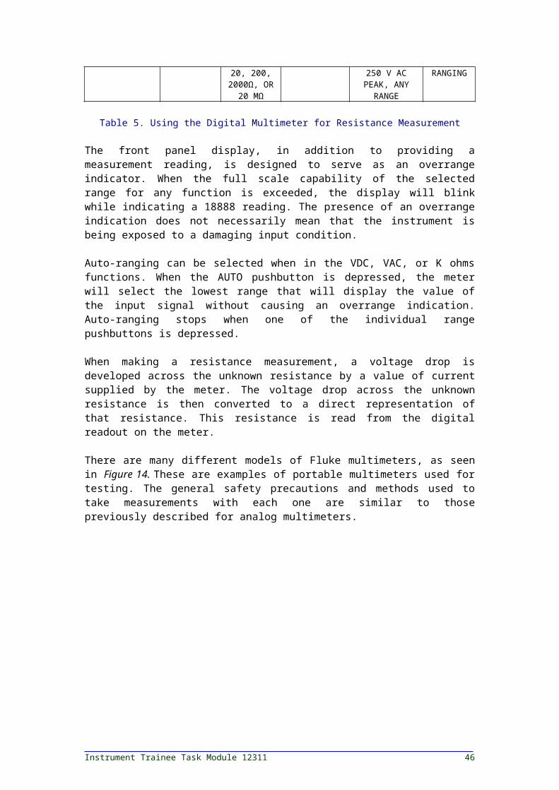
Table 5. Using the Digital Multimeter for Resistance Measurement
The front panel display, in addition to providing a measurement reading, is designed to serve as an overrange indicator. When the full scale capability of the selected range for any function is exceeded, the display will blink while indicating a 18888 reading. The presence of an overrange indication does not necessarily mean that the instrument is being exposed to a damaging input condition.
Cable Testing — Module 12311 37
Auto-ranging can be selected when in the VDC, VAC, or K ohms functions. When the AUTO pushbutton is depressed, the meter will select the lowest range that will display the value of the input signal without causing an overrange indication. Auto-ranging stops when one of the individual range pushbuttons is depressed.
When making a resistance measurement, a voltage drop is developed across the unknown resistance by a value of current supplied by the meter. The voltage drop across the unknown resistance is then converted to a direct representation of that resistance. This resistance is read from the digital readout on the meter.
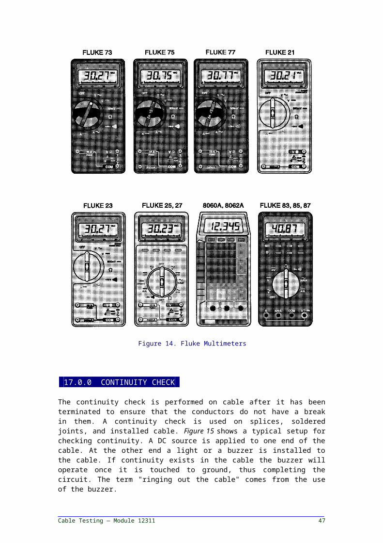
There are many different models of Fluke multimeters, as seen in Figure 14. These are examples of portable multimeters used for testing. The general safety precautions and methods used to take measurements with each one are similar to those previously described for analog multimeters.
Figure 14. Fluke Multimeters
Instrument Trainee Task Module 12311 38
17.0.0 CONTINUITY CHECK-
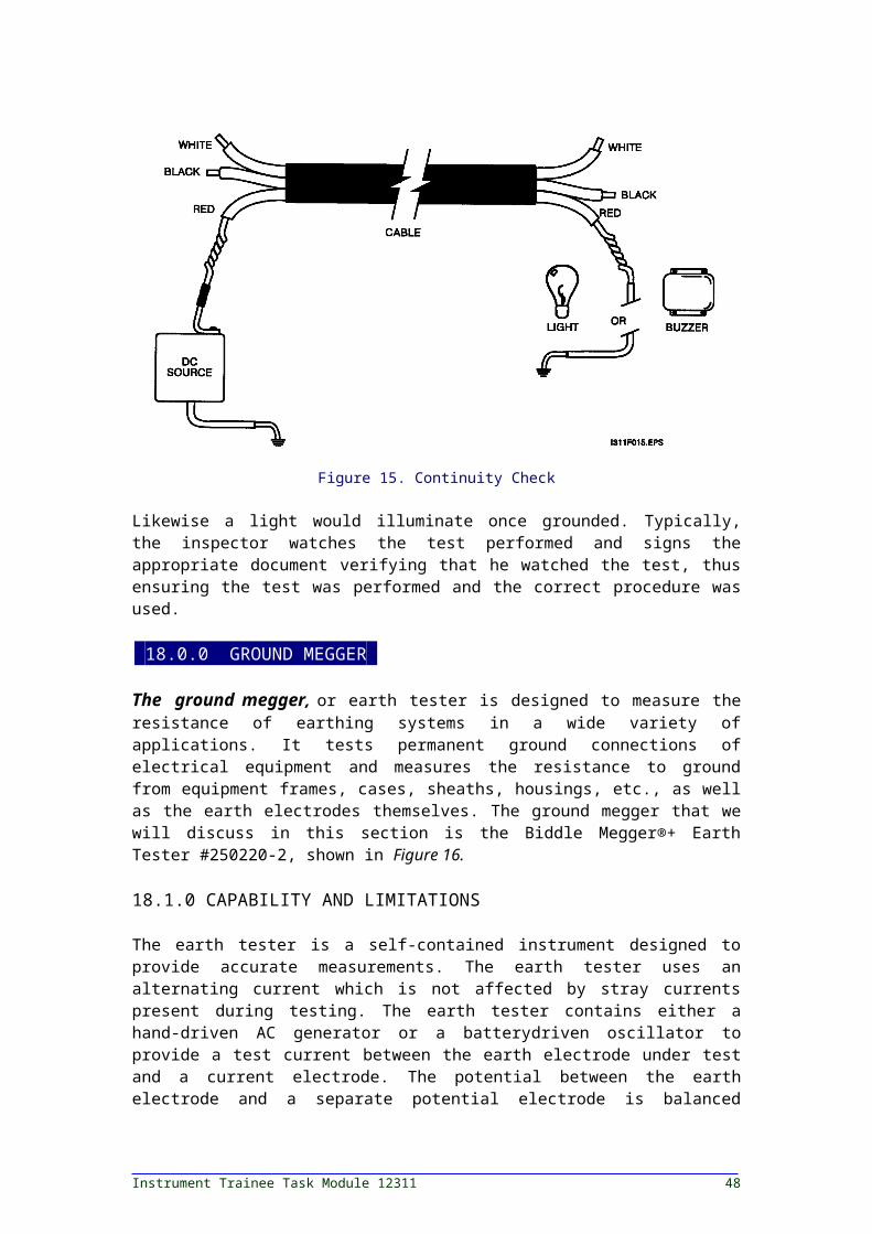
The continuity check is performed on cable after it has been terminated to ensure that the conductors do not have a break in them. A continuity check is used on splices, soldered joints, and installed cable. Figure 15 shows a typical setup for checking continuity. A DC source is applied to one end of the cable. At the other end a light or a buzzer is installed to the cable. If continuity exists in the cable the buzzer will operate once it is touched to ground, thus completing the circuit. The term "ringing out the cable" comes from the use of the buzzer.
Figure 15. Continuity Check
Likewise a light would illuminate once grounded. Typically, the inspector watches the test performed and signs the appropriate document verifying that he watched the test, thus ensuring the test was performed and the correct procedure was used.
18.0.0 GROUND MEGGER-
The ground megger, or earth tester is designed to measure the resistance of earthing systems in a wide variety of applications. It tests permanent ground connections of electrical equipment and measures the resistance to ground from equipment frames, cases, sheaths, housings, etc., as well as the earth electrodes themselves. The ground megger that we will discuss in this section is the Biddle Megger®+ Earth Tester #250220-2, shown in Figure 16.
18.1.0 CAPABILITY AND LIMITATIONS
The earth tester is a self-contained instrument designed to provide accurate measurements. The earth tester uses an alternating current which is not affected by stray currents present during testing. The earth tester contains either a hand-driven AC generator or a batterydriven
Cable Testing — Module 12311 39
oscillator to provide a test current between the earth electrode under test and a current electrode. The potential between the earth electrode and a separate potential electrode is balanced against a voltage which is generated from the AC output via a current transformer across the three resistance decades. The out-of-balance current caused by the difference of potentials is rectified and drives a zero-center meter.
Figure 16. Megger Null Balance Earth Testers
The null balance method means that, at balance, no current flows through the potential electrode, and therefore, the resistance of the potential electrode does not affect the reading. Lead resistances are not significant and may be eliminated by following recommended test procedures.
When the meter is balanced, the resistance in ohms is read from the resistance decade switches in combination with the range multiplier switch. Numerical readout of resistance has the advantages of no pointer reading error and the reading remains available until the next test is made.
18.2.0 OPERATING CONNECTIONS
Before setting up an earth electrode test, spacing requirements and location of test rods must be determined according to the following discussion.
Fall-of-potential or 3-point method is commonly used for single rod or small earth grids. This involves positioning current and potential rods C and P as shown in Figure 17 and connecting
Instrument Trainee Task Module 12311 40
Figure 17. Positioning Ground Rods in Relation to the Electrode Under Test
these by suitable cables to the earth tester to complete the current and voltage circuit. The tester is calibrated to read directly the resistance of the electrode E under test. To obtain a valid reading, the current rod must be properly located. Since both possess spheres of influence, the C2 rod must be sufficiently remote to prevent these areas from overlapping. Furthermore, the potential rod must lie between these two areas, preferably along a straight line between them.
In Figure 17, the dimensions of the spheres of influence of E and C are frequently unknown. To allow a safe margin, the distance chosen for EC may be quite high. It is also necessary to experiment with the location of P.
However, by mathematical analyses and shown by actual test the true resistance of the electrode to be tested is equal to the measured resistance when the distance EP is equal to 62% of the distance EC.
The potential electrode P2 maybe inserted at 50% and 75% of the distance EC to verify the measured resistance. In some cases, C2 and P2 may be relocated and the resistance measured again. The average of the measured resistances may be used at the true value.
18.3.0 SINGLE RODS AND SMALL GRIDS
For single rods and small grids, the current electrode C2, as seen Figure 18, should be 100 feet from the electrode under test E.
Cable Testing — Module 12311 41

Figure 18. Connections for Testing Resistance to Earth of an Earth Electrode
The potential electrode P2 should be inserted at 62% of this distance in a straight line with the other two.
18.4.0 LARGE EARTH ELECTRODE SYSTEMS OR LARGE AREA GROUND GRIDS
In general, the three-point or fall-of-potential method is also applicable to large area earth electrodes. However, the distance to the C2 current rod should be about five times the largest dimensions or diagonal of the earth electrode or ground grid area. The P2 potential rod should then be positioned at 62% of the distance from the center of the grid to the C2 rod. See Figure 19.
If the P2 rod is driven at several locations, a curve can be drawn for resistance versus distance, typically S-shaped, and the true value of the resistance of the earth electrode will be represented by the point at which the slope of the curve reverses. Usually this point is at the 62% distance previously noted.
Instrument Trainee Task Module 12311 42
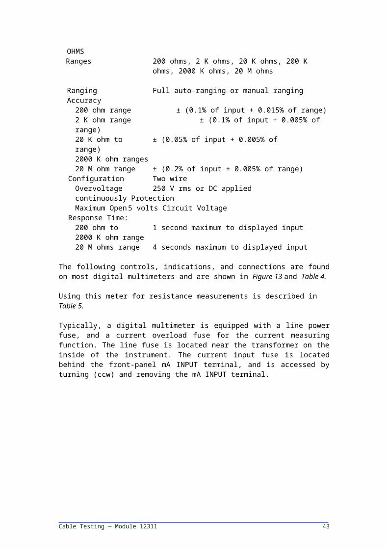
Figure 19. Typical Curve for Earth Electrode ResistanceVersus Distance from Electrode to Cz Rod
18.5.0 OPERATING PROCEDURES
Since proper operation of the equipment depends on correct use of the controls, the markings and function of these controls must be studied before using the tester.
All operating controls used on the earth tester are listed in Table 6 and Figure 20 shows the arrangement of the operating controls on the earth tester.
The earth tester contains either a hand-driven oscillator, or a battery powered oscillator, which passes current through the resistance under test from terminal C1 to C2. The consequent potential across terminals Pl and P2, causes a meter to deflect as seen Figure 20.
This potential is balanced by an equal and opposite potential produced across an adjustable resistance in the instrument with the result that, at balance, no current flows in the potential circuit. The measured values are unaffected by ground rod resistances within wide limits. Stray currents in the soil may produce movement of the pointer but will disappear when the generator is turned for the hand-cranked instrument, or the operating pushbutton is depressed for the battery-operated instrument.
With the earth tester connected for the test required, operate the earth tester as follows. Refer to Figure 20 for controls and indicators.
Cable Testing — Module 12311 43

CONTROL FUNCTION
HAND-CRANK AND BATTERY-OPERATED EARTH TESTERS
C1 binding post
C2 binding post
P1 binding post
P2 binding post
Range multiplier switch
Resistance decade switches (3 each)
Meter
Provides AC current to earth electrode under test.
Provides return path for AC current
Provides AC voltage connection to earth electrode under test.
Provide AC voltage connection to potential electode grounding rod.
Provides four ranges: X.01, X.1, X1, X10.
Digital display from 001 to 999.
Center reading indicates null balance.
BATTERY-OPERATED EARTH TESTER ONLY
Operation pushbutton
B position on range multiplier switch
Meter battery test scale
Applies output voltage. Applies output batteries to meter when range multiplier switch is moved to B multiplier.
To display battery output on meter.
Indicates condition of batteries.
HAND-CRANKED EARTH TESTER ONLY
G binding post (Cat. No. 250220 only)
Hand-crank
Provides a bypass path to a guard rod for leakage current within the instrument.
Operates generator to provide test voltage and current.
Table 6. Operating Controls
WARNING! Remember that rubber gloves should be wom during operation of the earth tester as a precaution against accidental high potentials on the structure under test.
1. Set the range multiplier switch to the x 0.01 position and each of the balancing resistor dials to 9 (9, 9, 9 left to right, respectively).
2. Tum the hand-crank clockwise about two revolutions per second for the handcranked earth tester, or press operating pushbutton for the battery-operated earth tester, and note the deflection on the meter.
Instrument Trainee Task Module 12311 44
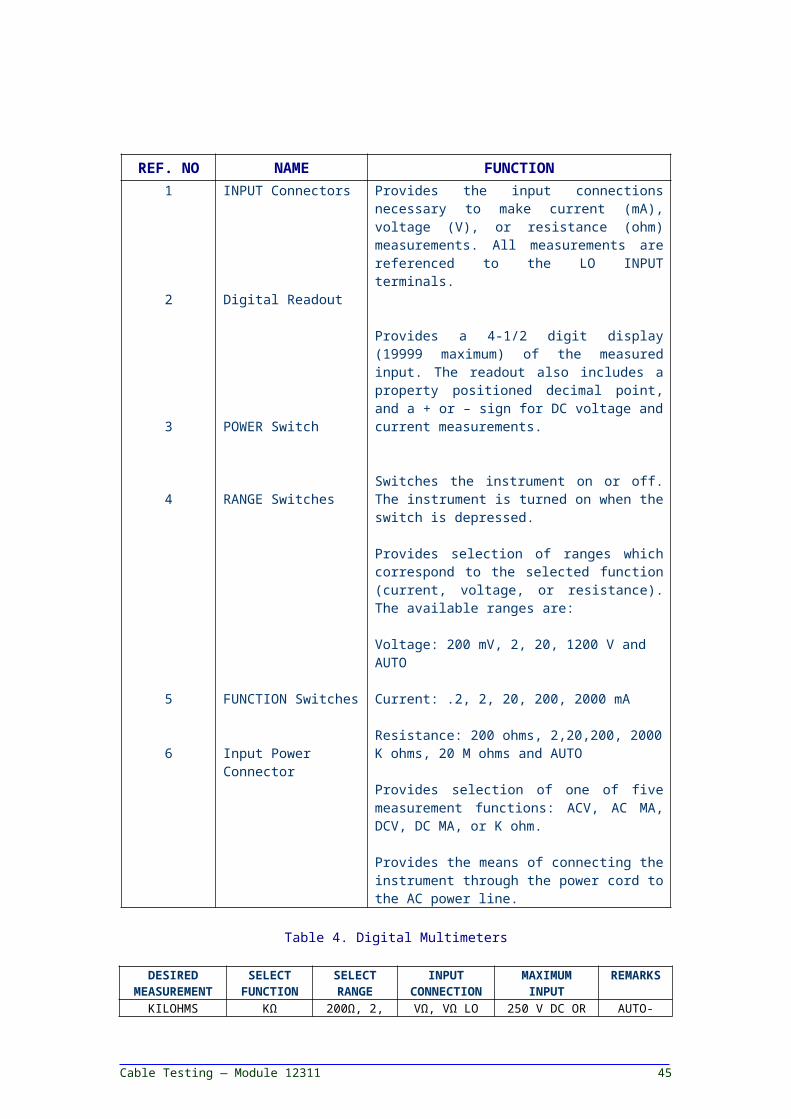
Figure 20. Megger Null Balance Earth Tester, Controls, and Indicators for Battery-Operated and Hand-Cranked Models
3. If deflection is to the right (+), increase resistance factor by setting the range multiplier switch to the x 0.1 position. Note the position of the pointer on the meter.
4. If deflection is to the left (-) proceed to the next step. If deflection is still to the right continue to increase the resistance factor with the range multiplier switch until the deflection goes to the left (-).
5. When deflection is to the left (-) decrease the values of the resistance decades, digit by digit, starting with the left dial then the center dial, and finally the right dial until the meter pointer is at the center. Whenever the reading goes to the right (+), the dial has been turned too far.
6. If using the hand-cranked earth tester, increase the cranking speed of the generator to about 160 rpm (about 2-1/2 revolutions of the hand-crank per second) for maximum sensitivity and to avoid the effects of stray currents in the soil.
NOTE: If stray current is present when using the hand-cranked earth tester, it may be necessary to increase the cranking speed depending upon the frequency of the stray current. Cranking speeds up to 200 rpm (about 3-1/2 revolutions of the hand-crank per second) may be required to accurately balance the meter.
7. Read the resistance directly off the dials (range multiplier times decade dials); this is the resistance of the earthing system under test. Example: If the Earth Tester is connected to an earth electrode
Cable Testing — Module 12311 45
in the recommended arrangement and the following settings result at null-balance:
- Range multiplier switch is set at 0.01 position.- Left resistance decade dial is set at position 3.- Center resistance decade dial is set at position
7.- Right resistance decade dial is set at position 6.
Then resistance measured is:376 x 0.01 = 3.76 ohms.
SUMMARY
This course has identified the different functions that cable testing accomplishes from charting deterioration of cables, to special repair testing. It listed the items that should be looked at during a cable inspection and defined types of cable failures, and their causes. The use of different types of test equipment used to test cables was covered, such as a megger, DC hi-pot, ohmmeter, and a ground megger. Specific types of tests used with this test equipment were listed, and safety precautions were covered in detail.
References
For advanced study of topics covered in this Task Module, the following works are suggested:
I.E.E.E. StandardsI.S.A. StandardsManufacturers data on test equipment.
Instrument Trainee Task Module 12311 46
SELF-CHECK REVIEW I PRACTICE QUESTIONS
1. What is the purpose of cable testing? a. To minimize danger to personnel. b. Acceptance testing.c. Special repair testing. d. All of the above.
2. When using a multimeter to measure resistance and corona is present, you should do what?a. Make sure the probe connections are tight.b. Set meter reading to the highest setting.c. Do not take reading until source of power is disconnected and
verified that it is deenergized.d. Use rubber gloves to make the measurement.
3. A megger can be used to measure energized lines or equipment.a. True.b. False.
4. Describe the procedures for using a megger.________________________________________________________________________________________________________________________________________
5. What is the DC over-potential test used extensively for? a. Breaking down incipient faults.b. Making time/current comparisons.c. Acceptance and maintenance of cables. d. All of the above.
6. Describe the Voltage Versus Leakage Current Test.______________________________________________________________________________________________________________________________________
7. Describe the Leakage Current Versus Time Test.______________________________________________________________________________________________________________________________________
8. Describe the Go/No-Go Over-Potential Test.______________________________________________________________________________________________________________________________________
9. When using an Ohmmeter, both series and shunt readings will be the same. a. True.b. False.
10. Describe the use of a ground megger.______________________________________________________________________________________________________________________________________
Cable Testing — Module 12311 47
PERFORMANCE / LABORATORY EXERCISES
1. Perform a continuity test.2. Perform a megger test on a cable.3. Using an ohmmeter, perform a resistance test on a cable.
ANSWERS TO SELF-SELF REVIEW / PRACTICE QUESTIONS
1. d2. c3. b4. Refer to page 12. 5. c6. Refer to page 20. 7. Refer to page 21. 8. Refer to page 22. 9. b10.Refer to page 42.
Instrument Trainee Task Module 12311 48