Embed Size (px)
Citation preview

Retain for future use.
Sepam Series 20Digital RelayInstallation Guide
Instruction Bulletin63230-216-208B1
7/2003Lavergne, TN, USA
worldbook.ir

© 2003 Schneider Electric All Rights Reserved
Read these instructions carefully and look at the equipment to become familiar with the device before trying to install, operate, service, or maintain it. The following special messages may appear throughout this bulletin or on the equipment to warn of potential hazards or to call attention to information that clarifies or simplifies a procedure.
The addition of either symbol to a “Danger” or “Warning” safety label indicates that an electrical hazard exists which will result in personal injury if the instructions are not followed.
This is the safety alert symbol. It is used to alert you to potential personal injury hazards. Obey all safety messages that follow this symbol to avoid possible injury or death.
NOTE: Provides additional information to clarify or simplify a procedure.
Electrical equipment should be installed, operated, serviced, and maintained only by qualified personnel. This document is not intended as an instruction manual for untrained persons. No responsibility is assumed by Square D for any consequences arising out of the use of this manual.
This equipment has been tested and found to comply with the limits for a Class A digital device, pursuant to part 15 of the FCC Rules. These limits are designated to provide reasonable protection against harmful interference when the equipment is operated in a commercial environment. This equipment generates, uses, and can radiate radio frequency energy and, if not installed and used in accordance with the instruction manual, may cause harmful interference to radio communications. Operation of this equipment in a residential area is likely to cause harmful interference in which case the user will be required to correct the interference at his own expense.
DANGERDANGER indicates an imminently hazardous situation which, if not avoided, will result in death or serious injury.
NOTICE
!
WARNINGWARNING indicates a potentially hazardous situation which, if not avoided, can result in death or serious injury.
CAUTIONCAUTION indicates a potentially hazardous situation which, if not avoided, can result in minor or moderate injury.
CAUTIONCAUTION, used without the safety alert symbol, indicates a potentially hazardous situation which, if not avoided, can result in property damage.
PLEASE NOTE
Class A FCC Statement

63230-216-208B1 Sepam Series 207/2003 Table of Contents
© 2003 Schneider Electric All Rights Reserved i
SECTION 1: INTRODUCTION Main Functions ............................................................................................ 1Relay Logic ............................................................................................ 2
Substation Feeder and Main: S Type............................................... 2Transformer: T Type......................................................................... 2Motor: M Type .................................................................................. 2Bus Voltage: B Type......................................................................... 3
Measurement ......................................................................................... 3Communication ...................................................................................... 3Diagnosis ............................................................................................... 3Control and monitoring ........................................................................... 3
Sepam Series 20 Selection Table .................................................... 4User Machine Interface ................................................................................ 5Expert UMI software .................................................................................... 5Symbol Key .................................................................................................. 6Metric Measurements/U.S. Equivalents ....................................................... 6Electrical Characteristics ............................................................................. 7Environmental Characteristics ..................................................................... 8
SECTION 2: SAFETY PRECAUTIONS ...................................................................................................................... 9
SECTION 3: INSTALLATION Installation of Sepam ................................................................................. 11Equipment Identification ............................................................................ 11
Sepam Model Identification .................................................................. 11Identification Labels ............................................................................. 11Package Labels .................................................................................... 12Connectors ........................................................................................... 13Sepam Models ..................................................................................... 14Package Contents ................................................................................ 15Instruction Materials ............................................................................. 15
Shipping, Handling, and Storage ............................................................... 16Sepam in its Original Packaging .......................................................... 16Sepam Installed in a Cubicle ................................................................ 16
Operating Environment .............................................................................. 16Assembly and Mounting ............................................................................ 17
Mounting of the Sepam main unit ........................................................ 18Flush-mounting in front panel ............................................................... 19Surface Mounting with AMT840 plate .................................................. 20Flush Mounting of the DSM303 module in the front panel ................... 21
Connection ................................................................................................. 23Sepam Components....................................................................... 23Installing Terminal Guard on Main Terminal Block (Ring Lug Terminals)..................................................................... 24
Connection of the Main Unit ................................................................. 24Wiring of the CCA620 (Main) connector:....................................... 25Wiring of the CCA622 (Main) connectors: ..................................... 25Characteristics of the 4 base unit relay outputs O1, O2, O3, O4. .. 25
Connection of Optional Input Output MES114 Module ........................ 26Connection ..................................................................................... 28Wiring of the Circuit Breaker/Contactor Trip Circuit........................ 28
Connection of Current Inputs ............................................................... 29Other Current Input Connection Schemes ..................................... 30Other residual current input connection schemes .......................... 31Ground Fault Current Measurement Method Summary without Neutral .............................................................................. 32
Ground Fault Current Measurement Method Summary with Neutral ................................................................................... 33
Connecting CTs.............................................................................. 34Connecting LPCTs ............................................................................... 37
CLP1 LPCT sensors....................................................................... 37
Sepam Series 20 63230-216-208B1Table of Contents 7/2003
© 2003 Schneider Electric All Rights Reservedii
ACE917 injection adapter ............................................................... 37CCA613 remote test plug ............................................................... 37Connection of Ground Fault CTs .................................................... 40Connection of voltage inputs .......................................................... 44Connection of voltage transformers................................................ 45Voltage Transformer Connections .................................................. 46
Connection of Optional Remote I/O Modules ....................................... 48Maximum configuration................................................................... 48DSM303 remote advanced UMI module......................................... 49Temperature sensor modules MET148-2 ....................................... 50Analog output module MSA141 ...................................................... 51
Communication interface module ......................................................... 522-wire RS 485 network interface ACE949-2 ................................... 534-wire RS 485 network interface ACE959 ...................................... 54Fiber optic interface ACE937.......................................................... 56
Implementation of the Modbus Network ..................................................... 57Communications Wiring ....................................................................... 57
Biasing the Communications Link................................................... 57Terminating the Communications Link ........................................... 58Communications Interface Wiring................................................... 58
Remote Operation via Ethernet LAN .................................................... 61Software ............................................................................................... 62POWERLOGIC System Manager Software ......................................... 62
SECTION 4: OPERATION User Machine Interfaces ............................................................................ 63Expert UMI (SFT2841) ............................................................................... 64
SFT2841 General screen organization ................................................ 65SFT2841 Use of the software ............................................................... 66
Basic UMI on Relay .................................................................................... 67Advanced UMI ............................................................................................ 68
Access Levels of Use ........................................................................... 68Access to measured and calculated data (operator level) ................... 68White keys for current operation .......................................................... 69Blue keys for parameter and protection setting ....................................72
Data Entry .................................................................................................. 75Passwords ............................................................................................75General or Protection Settings Entry .................................................... 75
Default parameters, all applications ........................................................... 76Commissioning ........................................................................................... 78
Principles and Methods ........................................................................ 78Protection relay testing ................................................................... 78
Sepam commissioning tests ................................................................. 78Testing and metering equipment required ...................................... 79Pre-test Settings Check .................................................................. 81
Checking of phase current input connection ........................................ 82Checking of residual current input connection ..................................... 83Checking phase voltage input connection ............................................ 84Checking of residual voltage input connection ..................................... 85Logic Input and Output ......................................................................... 86Validation of Protection Output and Custom Logic Functions ............. 87Optional Module Connection ................................................................87Test sheet Sepam series 40 ................................................................. 88Shutdown of the base unit if problems are identified ............................ 89Downgraded operation ......................................................................... 89RTD fault .............................................................................................. 89Other faults ........................................................................................... 90Maintenance ......................................................................................... 90Getting Technical Support .................................................................... 90

63230-216-208B1 Sepam Series 207/2003 Digital Relay
© 2003 Schneider Electric All Rights Reserved 1
SECTION 1— INTRODUCTION
MAIN FUNCTIONS The Sepam 1000+ Digital Relay is manufactured by Merlin Gerin in France. Merlin Gerin is a subsidiary of Schneider Electric, as is Square D. The Sepam 1000+ instruction materials shipped with your Sepam 1000+ contain all the information you will need to install and operate the Sepam 1000+.
The Sepam 1000+ features a modular design, Input/Output (I/O) and temperature options, and Modbus communications for easy integration into a POWERLOGIC Power Monitoring and Control System. Two types of displays are available: the basic User Machine Interface (UMI) and the Advanced UMI with LCD display.
Figure 1: Sepam 1000+—A modular solution
Figure 2: Sepam 1000+ with basic UMI and with fixed advanced UMI

Sepam Series 20 63230-216-208B1Digital Relay 7/2003
© 2003 Schneider Electric All Rights Reserved2
Figure 3: Example of an SFT2841 software screen (expert UMI)
The Sepam 1000+ series 20 family of protection and metering units is designed for the operation of machines and electrical distribution networks of industrial installations and utility substations for all levels of voltage.
The Sepam 1000+ series 20 family consists of simple, high-performing solutions, suited to demanding applications that call for current or voltage metering.
Table 1: Application Selector Guide
Relay Logic
Substation Feeder and Main: S Type • Detection of phase-to-phase and phase-to-ground short circuits
• Detection of unbalanced power source
• Recloser
Transformer: T Type • Detection of internal faults and overloads
• Thermal overload protection suited to cooling modes
Motor: M Type • Detection of internal faults, network related, and load faults
• Monitoring of motor starting conditions
Selector Criteria Series 20 Series 40*
AC Measurements I V V I,V,P,E I,V,P,E I,V,P,E
Specific Relay Functions81RdF/dt(RoCoF)
67N,67NSDir Grd O/C
67,67N,67NSDir Grd O/CDir Ph O/C
Application
SubstationLong Feeder(High Ixc)Mains in ParallelClosed Loop
S20 S40S41
S42S42
TransformerMains in Parallel
T20 T40T42
MotorLong Feeder (High Ixc)
M20M41
Generator G40Busbar (Voltage Mon)Gen/Utility in Parallel
B21B22
*Not covered in this instruction bulletin.Note: Ixc = Capacitive

63230-216-208B1 Sepam Series 207/2003 Digital Relay
© 2003 Schneider Electric All Rights Reserved 3
Bus Voltage: B Type • Monitoring of voltage and frequency abnormal operating conditions
• Rate of change of frequency protection for a fast and reliable disconnection
Measurement All necessary electrical parameters:
• phase and residual currents
• average and peak demand currents
• phase-to-neutral, phase-to-phase, and residual voltages
• positive and negative sequence voltages
• frequency
• optional eight RTD inputs measure motor or transformer temperatures (two setpoints each)
Communication Sepam series 20 is totally compatible with the Modbus communication standard.
All the data needed for centralized equipment management from a remote monitoring and control system are available via the Modbus communication port:
• reading: all measurements, alarms, protection settings,...
• writing: breaking device remote control orders,... .
Diagnosis 3 types of diagnosis data for improved operation:
• network and machine diagnosis: tripping current, context of the last 5 trips, unbalance ratio, disturbance recording
• switchgear diagnosis: cumulative breaking current, trip circuit supervision, operating time.
• diagnosis of the protection unit and additional modules: continuous self-testing, watchdog.
Control and monitoring Circuit breaker program logic is ready to use, requiring no auxiliary relays or additional wiring.

Sepam Series 20 63230-216-208B1Digital Relay 7/2003
© 2003 Schneider Electric All Rights Reserved4
Sepam Series 20 Selection Table
Functions Type of SepamSubstation Transformer Motor Busbar
Protections ANSI code S20 T20 M20 B21 (4) B22Phase overcurrent (1) 50/51 4 4 4Earth fault (or neutral) (1) 50N/51N 50G/51G 4 4 4Unbalance / negative sequence 46 1 1 1Thermal overload 49 RMS 2 2Phase undercurrent 37 1Excessive starting time, locked rotor 48/51LR 1Starts per hour 66 1Positive sequence undervoltage 27D/47 2 2Remanent undervoltage 27R 1 1Phase-to-phase undervoltage 27 2 2Phase-to-neutral undervoltage 27S 1 1Maximum de tension composée 59 2 2Phase-to-phase overvoltage 59N 2 2Underfrequency 81L 2 2Overfrequency 81H 1 1Rate of change of frequency 81R 1Recloser (4 cycles) 79 vThermostat / Buchholz vTemperature monitoring(with MET148, 2 set points per sensor)
38/49T v v
MeteringPhase current I1,I2,I3 RMS b b b
Residual current Io b b b
Average current I1, I2, I3 b b b
Peak demand phase current IM1,IM2,IM3 b b b
Line voltage U21, U32, U13 b b
Phase-to-neutral voltage V1, V2, V3 b b
Residual voltage Vo b b
Positive sequence voltage / rotation direction b b
Frequency b b
Temperature measurement v v
Network and machine diagnosis
Tripping current I1,I2,I3, Io b b b
Unbalance ratio / negative sequence current Ii b b b
Running hours counter / operating time b b
Thermal capacity used b b
Remaining operating time beforeoverload tripping
b b
Waiting time after overload tripping b b
Starting current and time / overload b
Start inhibit time delay, number of starts before inhibition
b
Disturbance recording b b b b b
Switchgear diagnosticCumulative breaking current2 b b b
Trip circuit supervision v v v v v
Number of operations v v v
Operating time v v v
Charging time v v v
Self-diagnosis
Watchdog b b b b b

63230-216-208B1 Sepam Series 207/2003 Digital Relay
© 2003 Schneider Electric All Rights Reserved 5
USER MACHINE INTERFACE 2 levels of User Machine Interface (UMI) are available depending on the user’s needs:
• basic UMI:
an economical solution for installations that do not require local operation (run via a remote monitoring and control system)
• fixed or remote advanced UMI:
a graphic LCD display and 9-key keypad are used to display the measurement and diagnosis values, alarm and operating messages and provide access to protection and parameter setting values, for installations that are operated locally.
EXPERT UMI SOFTWARE The SFT2841 PC software tool gives access to all the Sepam functions, with all the facilities and convenience provided by a Windows type environment.
Output relay test (2) v v v v v
Control and monitoring
Circuit breaker / contactor control (3) v v v v v
Logic discrimination v v v
4 addressable logic outputs b b b b b
Additional modules
MET148-2 module - 8 temperature sensor inputs v v
MSA141 module - 1 low level analog output v v v v vMES114, MES114E, or MES114F module - (10I/4O) v v v v vACE949-2 module - (2-wire) or ACE959 (4-wire) RS 485 interface v v v v vb standard, v according to parameter setting and MES114 or MET148 input/output module options.(1) 4 relays with the exclusive possibility of logic discrimination or switching from one 2-relay group of settings to another 2-relay group (exclusive choice).(2) with advanced UMI option only.(3) for shunt trip unit or undervoltage release coil according to parameter setting.(4) performs B20 type functions.

Sepam Series 20 63230-216-208B1Digital Relay 7/2003
© 2003 Schneider Electric All Rights Reserved6
SYMBOL KEY Electrical symbols commonly used in Europe are found throughout this instruction bulletin. Those symbols, which may be unfamiliar to some users in North America, are explained below.
METRIC MEASUREMENTS/U.S. EQUIVALENTS
Some of the measurements provided in this instruction bulletin are metric. Users in the United States may find the following conversion chart helpful.
Table 2: Metric Conversions
Metric equals U.S. Equivalent
25.4 mm (millimeters) = 1 inch
0.4536 kg (kilograms) = 1 pound
° C (Centigrade) x 1.8 + 32 = ° F (Fahrenheit)
Table 3: Wire Size Conversions
Metric Area mm2 equals AWG Gauge
0.20 = 24
0.33 = 22
0.50 = 20
0.78 = 18
1.3 = 16
2.0 = 14
3.1 = 12
5.3 = 10
63230-216-208B1 Sepam Series 207/2003 Digital Relay
© 2003 Schneider Electric All Rights Reserved 7
ELECTRICAL CHARACTERISTICS
Analog inputs
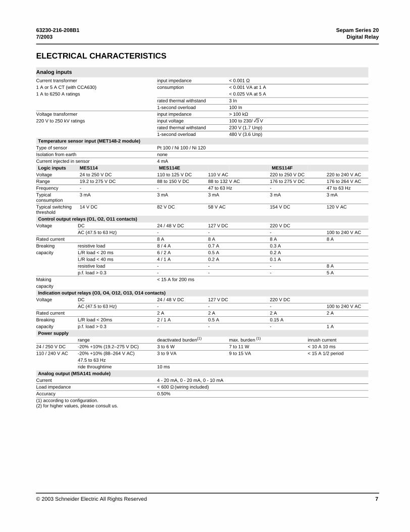
Current transformer input impedance < 0.001 Ω1 A or 5 A CT (with CCA630) consumption < 0.001 VA at 1 A1 A to 6250 A ratings < 0.025 VA at 5 A
rated thermal withstand 3 In1-second overload 100 In
Voltage transformer input impedance > 100 kΩ220 V to 250 kV ratings input voltage 100 to 230/ 3V
rated thermal withstand 230 V (1.7 Unp)1-second overload 480 V (3.6 Unp)
Temperature sensor input (MET148-2 module)Type of sensor Pt 100 / Ni 100 / Ni 120Isolation from earth noneCurrent injected in sensor 4 mALogic inputs MES114 MES114E MES114F
Voltage 24 to 250 V DC 110 to 125 V DC 110 V AC 220 to 250 V DC 220 to 240 V ACRange 19.2 to 275 V DC 88 to 150 V DC 88 to 132 V AC 176 to 275 V DC 176 to 264 V ACFrequency - - 47 to 63 Hz - 47 to 63 HzTypical consumption
3 mA 3 mA 3 mA 3 mA 3 mA
Typical switching threshold
14 V DC 82 V DC 58 V AC 154 V DC 120 V AC
Control output relays (O1, O2, O11 contacts)Voltage DC 24 / 48 V DC 127 V DC 220 V DC
AC (47.5 to 63 Hz) - - - 100 to 240 V ACRated current 8 A 8 A 8 A 8 ABreaking resistive load 8 / 4 A 0.7 A 0.3 Acapacity L/R load < 20 ms 6 / 2 A 0.5 A 0.2 A
L/R load < 40 ms 4 / 1 A 0.2 A 0.1 Aresistive load - - - 8 Ap.f. load > 0.3 - - - 5 A
Making < 15 A for 200 mscapacityIndication output relays (O3, O4, O12, O13, O14 contacts)
Voltage DC 24 / 48 V DC 127 V DC 220 V DCAC (47.5 to 63 Hz) - - - 100 to 240 V AC
Rated current 2 A 2 A 2 A 2 ABreaking L/R load < 20ms 2 / 1 A 0.5 A 0.15 Acapacity p.f. load > 0.3 - - - 1 APower supply
range deactivated burden(1) max. burden (1) inrush current24 / 250 V DC -20% +10% (19.2–275 V DC) 3 to 6 W 7 to 11 W < 10 A 10 ms110 / 240 V AC -20% +10% (88–264 V AC) 3 to 9 VA 9 to 15 VA < 15 A 1/2 period
47.5 to 63 Hzride throughtime 10 ms
Analog output (MSA141 module)Current 4 - 20 mA, 0 - 20 mA, 0 - 10 mALoad impedance < 600 Ω (wiring included)Accuracy 0.50%(1) according to configuration.(2) for higher values, please consult us.

Sepam Series 20 63230-216-208B1Digital Relay 7/2003
© 2003 Schneider Electric All Rights Reserved8
ENVIRONMENTAL CHARACTERISTICS
Electromagnetic compatibility IEC / EN standard Level / Class Value
Emission testsDisturbing field emission EN 55022 / CISPR22 AConducted disturbance emission EN 55022 / CISPR22 BImmunity tests – Radiated disturbances
Immunity to radiated fields 60255-22-3 / 61000-4-3 III 10 V/mElectrostatic discharge 60255-22-2 / 61000-4-2 III 8 kV air
6 kV contactImmunity tests – Conducted disturbances
Immunity to conducted RF disturbances 61000-4-6 III 10 VFast transient bursts 60255-22-4 / 61000-4-4 IV1 MHz damped oscillating wave 60255-22-1 III 2.5 kV MC
1 kV MDImpulse waves 61000-4-5 IIIVoltage interruptions 60255-11 100% 20 ms
Mechanical robustness IEC / EN standard Level / Class ValueIn operation
Vibrations 60255-21-1 2 1 GnShocks 60255-21-2 2 10 Gn / 11 msEarthquakes 60255-21-3 2De-energized
Vibrations 60255-21-1 2 (1) 2 GnShocks 60255-21-2 2 (1) 30 Gn / 11 msJolts 60255-21-2 2 (1) 20 Gn / 16 ms
Climatic withstand IEC / EN standard Level / Class ValueIn operation
Exposure to cold 60068.2.1 Ad -25°CExposure to dry heat 60068.2.2 Bd +70°CContinuous exposure to damp heat 60068.2.3 Ca 93% HR; 40°C
10 daysTemperature variation with specified variation rate 60068.2.14 Nb –25 °C to +70 °C
5°C/minSalt mist 60068-2-52 Kb / 2Influence of corrosion 60654-4 Clean industrial airIn storage (4)
Exposure to cold 60068.2.1 Ab -25 °CExposure to dry heat 60068.2.2 Bb +70 °CContinuous exposure to damp heat 60068.2.3 Ca 93% RH; 40 °C
56 days
Standards IEC / EN standard Level / Class ValueEnclosure tests
Front panel tightness 60529 IP52 Other panels closed, except for rear panel IP20
NEMA Type 12 with gasket supplied
Fire withstand 60695-2-11 650°C with glow wireElectrical tests
Ground continuity 61131-2 30 A1.2/50 µs impulse wave 60255-5 5 kV (2)
Power frequency dielectric withstand 60255-5 2 kV 1 mn (3)
CertificationCE generic standard EN 50081-2 European directives
89/336/EEC Electromagnétic Compatibility (EMC) Directive92/31/EEC Amendment92/68/EEC Amendment73/23/EEC Low Voltage Directive93/68/EEC Amendment
UL - UL508 - CSA C22.2 n° 14-95 File E212533CSA CSA C22.2 n° 94-M91 / n° 0.17-00 File E210625(1) Results given for intrinsic withstand, excluding support equipment(2) Except for communication: 3 kV in common mode and 1kV in differential mode(3) Except for communication: 1 kVrms(4) Sepam must be stored in its original packing.

63230-216-208B1 Sepam Series 207/2003 Digital Relay
© 2003 Schneider Electric All Rights Reserved 9
SECTION 2— SAFETY PRECAUTIONS
This chapter contains important safety precautions that must be followed before attempting to install, operate, service, or maintain electrical equipment. Carefully read and follow the safety precautions outlined below.
DANGERHAZARD OF ELECTRIC SHOCK, BURN, OR EXPLOSION
• Only qualified workers should install this equipment. Such work should be performed only after reading this entire set of instructions.
• NEVER work alone.• Turn off all power supplying this equipment before working on or inside.• Always use a properly rated voltage sensing device to confirm that all
power is off.• Before performing visual inspections, tests, or maintenance on this
equipment, disconnect all sources of electric power. Assume that all circuits are live until they have been completely de-energized, tested, and tagged. Pay particular attention to the design of the power system. Consider all sources of power, including the possibility of backfeeding.
• Beware of potential hazards, wear personal protective equipment, carefully inspect the work area for tools and objects that may have been left inside the equipment.
• Use caution while removing or installing panels so that they do not extend into the energized bus; avoid handling the panels, which could cause personal injury.
• The successful operation of this equipment depends upon proper handling, installation, and operation. Neglecting fundamental installation requirements may lead to personal injury as well as damage to electrical equipment or other property.
• Before performing Dielectric (Hi-Pot) or Megger testing on any equipment in which the relay is installed, disconnect all input and output wires to the relay. High voltage testing may damage electronic components contained in the relay.
Failure to follow these instructions will result in death or serious injury.

Sepam Series 20 63230-216-208B1Digital Relay 7/2003
© 2003 Schneider Electric All Rights Reserved10

63230-216-208B1 Sepam Series 207/2003 Digital Relay
© 2003 Schneider Electric All Rights Reserved 11
SECTION 3— INSTALLATION
INSTALLATION OF SEPAM We recommend that you follow the instructions given in this document for quick and correct installation of your Sepam Series 20:
• equipment identification
• assembly and mounting
• connection of current inputs and voltage inputs
• connection of optional modules
• connection of power supply and ground
• checking prior to commissioning.
EQUIPMENT IDENTIFICATION
Sepam Model Identification Using an advanced UMI, you can identify which Series 20 model you have by pressing the status key four times. See Figure 4. The model is identified as the "type."
Figure 4: Sepam Model Identification
Identification Labels To identify a Sepam, check the 2 labels on the right side panel of the base unit which describe the product’s functional and hardware features.
• hardware reference and designation label
reset
I onon 0 off
clear
Type = T20
Sepam transfo 1
Sepam V0013 MSA141 V0001
TripextI >> 51I>51 Io >> 51NIo > 51N
UMI V0013 MET148 V0002
About Sepam
Status Key
User Machine Interfacemodel
2
U
NOTE: See Figure 5 on page 12 for the location of this label on the main unit.
1

Sepam Series 20 63230-216-208B1Digital Relay 7/2003
© 2003 Schneider Electric All Rights Reserved12
• software reference and designation label
• Label for units sold in the United States
Figure 5: Equipment label locations
Package Labels If the relay is still in its original package, you can identify it by comparing catalog number information similar to label 3 above with the description in “Sepam Models” on page 14.
2
NOTE: See Figure 5 for the location of this label on the main unit.
2
2
A 4-alpha suffix denotes a deviation from one or more of these standard features:
• Second language = French• Connection for CT• Terminal blocks for A for ring
lugs For example SP1M20A-USLS:• for Spanish• LPCT connector, and
• screw compression type TBs
NOTE: See Figure 5 for the location of this label on the main unit.
3
1 and 2 (not shown)
3 (U.S. label)

63230-216-208B1 Sepam Series 207/2003 Digital Relay
© 2003 Schneider Electric All Rights Reserved 13
Connectors Each Sepam Series 20 main unit comes with one of the following unmounted connectors:
The other connectors come mounted and screw-locked on the modules.
MER
LING
ERIN
1. CCA 630* connector for connecting CTs to Sepam Series 20 (S20, T20, M20)
* or CCA670 connector for LPCT sensors (See Figure 9 on page 39)
2. CCT640 voltage connector for VTs on Sepam Series 20 type B21, B22. See “Connection of voltage transformers” on page 45.

Sepam Series 20 63230-216-208B1Digital Relay 7/2003
© 2003 Schneider Electric All Rights Reserved14
Sepam Models
CAUTIONLOSS OF PROTECTION
If ac control power is used, a backup power source is recommended to supply control power to the Sepam 1000+ during a power outage.
Failure to observe this precaution can cause the Sepam 1000+ to become inoperative if primary control power is lost.
Catalog Number Description
Digital Relay SEPAM Series 20 (Main Unit)SP1 S20 A S20 (substa),adv UMI, 24-250 Vdc&120-240 Vac①
SP1 B21 A B21 (bus/voltage),adv UMI, 24-250 Vdc&120-240 Vac①
SP1 B22 A B22 (bus/voltage),adv UMI, 24-250 Vdc&120-240 Vac①
SP1 T20 A T20 (transf),adv UMI, 24-250 Vdc&120-240 Vac①
SP1 M20 A M20 (motor),adv UMI, 24-250 Vdc&120-240 Vac①
SP1 S20 B S20 (substa),basic UMI, 24-250 Vdc&120-240 Vac①
SP1 B21 B B21 (bus/voltage),basic UMI, 24-250 Vdc&120-240 Vac①
SP1 B22 B B22 (bus/voltage),basic UMI, 24-250 Vdc&120-240 Vac①
SP1 T20 B T20 (transf),basic UMI, 24-250 Vdc&120-240 Vac①
SP1 M20 B M20 (motor),basic UMI, 24-250 Vdc&120-240 Vac①
Accessories For Digital Relay SEPAM Series 20MES114 10 input / 4 output module, 24–250 Vdc control powerMES114E 10 input / 4 output module, 125 Vdc/120 Vac control powerMES114F 10 input / 4 output module, 250 Vdc/240 Vac control powerMET1482 8 RTD resistance temperature detector input module②
MSA141 Analog output module②
DSM303 Remote advanced UMI (requires cable CCA77x see below)ACE959 RS485 4-wire interface module ③ (req. ext. 24 Vdc control power)ACE949-2 RS485 2-wire interface module ③ (req. ext. 24 Vdc control power)
ACE937820 nM optical fiber interface module (control power supplied by Sepam main unit via CCA612 cable)
CCA770 2 ft cable from analog I/O daisy chain to main unit②CCA772 2 m cable from analog I/O daisy chain to main unit②CCA774 4 m cable from analog I/O daisy chain to main unit②AMT840 Assembly plate for surface mounting of main unitCSH30 Interposing window CT for residual current input④CSH120 Ground sensor CT - 120 mm windowCSH200 Ground sensor CT - 200 mm windowACE990 Aux. CT for ground sensor CT ratio adjustment (for retrofit)ACE917 LPCT Injection AdaptorCCA613 LPCT Test Plug
Tools For Digital Relay Sepam Series 20SFT2841 kit Setting/operating software kit ➄① Ships with CCA630 CT connector (Figure 8 on page 34) [or CCA670 LPCT connector (see Figure 9 on page 39)] [or CCT640 VT connector (see “Connection of voltage transformers” on page 45)] and CCA622 terminal block (see Figure 7 on page 25).
② Analog I/O are DSM303, MET1482, MSA141. Maximum cable length from main unit to last device = 33 ft. (10 m).
③ Includes CCA612 cable for module to relay connection.
④ See 5A and 6A in “Ground Fault Current Measurement Method Summary without Neutral” on page 32 and 5B and 6B in “Ground Fault Current Measurement Method Summary with Neutral” on page 33.
➄ Includes SFT2826 waveform S/W+CCA783 cable for PC to relay connection.
Note: Contact Power Management Operation Technical Support for information on alternate control voltages, second language (other than French) on display, and special configuration. For technical support contact information, see “Getting Technical Support” on page 90.

63230-216-208B1 Sepam Series 207/2003 Digital Relay
© 2003 Schneider Electric All Rights Reserved 15
Package Contents Your Sepam 1000+ base unit is shipped in a single package with its connectors: a CCA630 for CTs (or CCA670 for LPCTs) (or CCT640 for VTs), and a 20 point ring lug type terminal block (CCA620, see page 24) for control power, ground sensor input, and 4 main unit outputs.
Instruction materials are also included (see “Instruction Materials” for details).
Optional accessories such as modules, current, and voltage input connector and cables come in separate packages.
NOTE: Sepam SFT 2841 software always ships in a separate package than the Sepam 1000+, even if ordered at the same time.
Instruction Materials Your Sepam Series 20 is shipped with the following instruction documents:
• Sepam 1000+ Installation Guide (this instruction bulletin), number 63230-216-208
• Sepam 1000+ Quick Start Guide, number 03146790FE-D0
• Contact Sheet/Registration Card, number 63220-060-79
This installation guide, the Sepam Series 20 Reference Guide 63230-216-224, and other instruction bulletins are available online at www.powerlogic.com.

Sepam Series 20 63230-216-208B1Digital Relay 7/2003
© 2003 Schneider Electric All Rights Reserved16
SHIPPING, HANDLING, AND STORAGE
Sepam in its Original PackagingTransport:Sepam may be shipped to any destination without taking any additional precautions by all usual means of transport.
Handling:Sepam may be handled without any particular care and can even withstand being dropped by a person handling it (person standing on floor).
Storage:Sepam may be stored in its original packaging, in an appropriate location for several years:b temperature between -25 °C and +70 °Cb humidity y 90 %.Periodic, yearly checking of the environment and the packaging condition is recommended.Once Sepam has been unpacked, it should be energized as soon as possible.
Sepam Installed in a CubicleTransport:Sepam may be transported by all usual means of transport in the customary conditions used for cubicles. Storage conditions should be taken into consideration for a long period of transport.
Handling:Should the Sepam fall out of a cubicle, check its condition by visual inspection and energizing.
Storage:Keep the cubicle protection packing for as long as possible. Sepam, like all electronic units, should not be stored in a damp environment for more than a month. Sepam should be energized as quickly as possible. If this is not possible, the cubicle reheating system should be activated.
OPERATING ENVIRONMENTOperation in a damp environmentThe temperature/relative humidity factors must compatible with the unit’s environmental withstand characteristics.If the use conditions are outside the normal zone, arrangements should be made before commissioning, such as providing air conditioning of the premises.
MT
1114
9
Operation in a polluted atmosphereSepam is designed to be used in a clean industrial environment as defined by IEC 60654-4 class 1. A contaminated industrial atmosphere components (such as the presence of chlorine, hydrofluoric acid, sulfur, solvents...) may cause corrosion of the electronic components, in which case environmental control arrangements should be made (such as closed, pressurized premises with filtered air, ...) before commissioning.

63230-216-208B1 Sepam Series 207/2003 Digital Relay
© 2003 Schneider Electric All Rights Reserved 17
ASSEMBLY AND MOUNTING
• Main Unit
The Sepam 1000+ main unit, whether equipped with basic or advanced UMI, flush mounts in a panel. Although an opening must be cut in the panel, no screws are necessary to mount the base unit. It is held in place by spring clips. For details, see “Flush-mounting in front panel” on page 19. Note: the maximum panel thickness is 0.135 inches (3.4 mm).
If used in conjunction with a remote advanced display, the main unit with basic UMI can also be surface mounted at the back of a compartment using the AMT840 plate. This allows access to the connectors on the back of the Sepam 1000+. For details, see “Surface Mounting with AMT840 plate” on page 20.
• User Machine Interface (UMI). There are two types:
— Advanced UMI, with graphic LCD display alarm LEDs and keypad
— Basic UMI, with LEDs and reset
For installation of the remote Advanced UMI (DSM 303), see “Flush Mounting of the DSM303 module in the front panel” on page 21.
NOTE: A remote advanced UMI connects to a main unit equipped with a basic UMI (see “Sepam Series 20 Selection Table” on page 4), and cannot be used with a main unit equipped with a fixed Advanced UMI.
Each main unit associated with a remote advanced UMI must be configured to accept such a connection. Once configured, if the remote advanced UMI is disconnected, a self-test alarm issues and LEDs illuminate (see “Maintenance” on page 89).
• Input/Output Module MES114, MES114E, or MES114F (optional)
For installation of these input/output modules on the back of the main unit, see page 24.
DANGERHAZARD OF ELECTRIC SHOCK, BURN, OR EXPLOSION
• Only qualified personnel should install this equipment. Such work should be performed only after reading this entire set of instructions.
• NEVER work alone.• Before performing visual inspections, tests, or maintenance on this
equipment, disconnect all sources of electrical power. Assume that all circuits are live until they have been completely de-energized, tested, and tagged. Pay particular attention to the design of the power system. Consider all sources of power, including the possibility of backfeeding.
• Turn off all power supplying the Sepam 1000+ and the equipment in which it is installed before installing and wiring the Sepam 1000+. Be aware that the Sepam 1000+ may be connected to a separate power source not derived from the equipment in which it is installed.
• Always use a properly rated voltage sensing device to confirm that all power is off.
• Beware of potential hazards, wear personal protective equipment, and carefully inspect the work areas for tools and objects that may have been left inside the equipment.
Failure to follow this instruction will result in death or serious injury.

Sepam Series 20 63230-216-208B1Digital Relay 7/2003
© 2003 Schneider Electric All Rights Reserved18
Mounting of the Sepam main unit The Sepam is simply flush-mounted and clamped, without requiring any additional screw type fastening.
MT11164
1. Turn off all power supplying the Sepam 1000+ and the equipment in which it is installed before installing and wiring the Sepam 1000+. Be aware that the Sepam 1000+ may be connected to a separate power source not derived from the equipment in which it is installed.
2. Always use a properly rated voltage sensing device to confirm that all power is off.
3. Present the product as indicated, making sure the metal plate is correctly entered in the groove at the bottom.
4. Tilt the product and press on the top part to clamp it with the clips.
slot
mountingclip

63230-216-208B1 Sepam Series 207/2003 Digital Relay
© 2003 Schneider Electric All Rights Reserved 19
Flush-mounting in front panel Assembly shown with advanced UMI and optional MES114 module.
• Weight = env. 4.2 lb (1.9 kg) [with option]
• Weight = env. 3.3 lb (1.5 kg) [without option]
MT11150
MT11151 MT10461
6 15/16(176)
6 19/64(160)
Top viewPanel front
8 3/4(222)
7 51/64(198)
3 7/8(98)
1 7/32(31)
Side view
6 3/8(162 ± 0.2)
7 61/64(202 ± 0.2)
Cut-out
Mounting plate thickness < 0.135 in (3.4 mm).

Sepam Series 20 63230-216-208B1Digital Relay 7/2003
© 2003 Schneider Electric All Rights Reserved20
Surface Mounting with AMT840 plate • Used to mount Sepam with basic UMI at the back of the compartment with access to connectors on the rear panel.
• Assembly associated with the use of the remote advanced UMI (DSM303).
MT10332
17/64 (6.5)
1 9/16(40)
1 9/16(40)
1 9/16(40)
1 9/16(40)
1 9/16(40)
19/32(15)
9 3/64(230)
8 1/2(216)
9 19/64(236)
6 15/16(176)
4 27/32(123) 3 27/32
(98)
Front View
Top View
63230-216-208B1 Sepam Series 207/2003 Digital Relay
© 2003 Schneider Electric All Rights Reserved 21
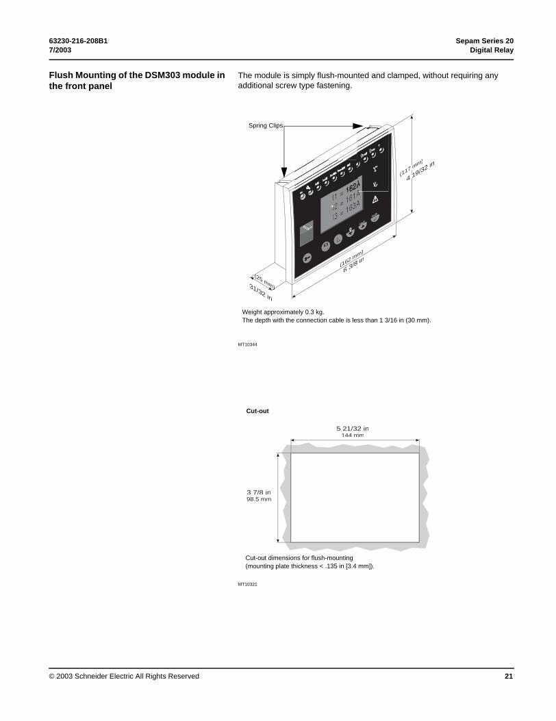
Flush Mounting of the DSM303 module in the front panel
The module is simply flush-mounted and clamped, without requiring any additional screw type fastening.
MT10344
MT10321
(162 mm)
(25 mm)
(
m)
rirrpp
reset
clear
31/32 in
6 3/8 in
(117 mm)
4 19/32 in
Weight approximately 0.3 kg.The depth with the connection cable is less than 1 3/16 in (30 mm).
Spring Clips
5 21/32 in144 mm
3 7/8 in98.5 mm
Cut-out
Cut-out dimensions for flush-mounting (mounting plate thickness < .135 in [3.4 mm]).

Sepam Series 20 63230-216-208B1Digital Relay 7/2003
© 2003 Schneider Electric All Rights Reserved22
MT10463
mounting clamp
4 19/32 in(117 mm)
19/32 in(15 mm)
3 25/32 in(96 mm)
maximum depthwith cable: 1 3/16 in (30 mm)
lateral outlet
13/32 in(10 mm)
Side view

63230-216-208B1 Sepam Series 207/2003 Digital Relay
© 2003 Schneider Electric All Rights Reserved 23
CONNECTION The Sepam connections are made to the removable connectors located on the rear surface. All the connectors are screw-lockable.
NOTE: All the terminals must be screwed tight, whether or not they are used.
Sepam Components
MT10305
Figure 6: Sepam Components
DANGERHAZARD OF ELECTRIC SHOCK, BURN, OR EXPLOSION
• Only qualified personnel should install this equipment. Such work should be performed only after reading this entire set of instructions.
• Turn off all power supplying the Sepam 1000+ and the equipment in which it is installed before installing and wiring the Sepam 1000+. Be aware that the Sepam 1000+ may be connected to a separate power source not derived from the equipment in which it is installed.
• Before wiring the main terminal block and installing the terminal guard shipped with the terminal block, turn off power to the Sepam 1000+ and any equipment wired to the terminal block.
• Always use a properly rated voltage sensing device to confirm that all power is off.
• The successful operation of this equipment depends upon proper handling, installation, setup, and operation. Neglecting fundamental installation requirements may lead to personal injury as well as damage to electrical equipment or other property.
Failure to follow this instruction will result in death or serious injury.
Main unit
Main unit connector [Screw-type connector shown (CCA620), or ring lug connector (CCA622).]
A
Output relays
CSH30, 120, 200 or ACE990 input
1A/5A CT current input connector (CCA630) or LPCT current input connector (CCA670)
or VT voltage input connector (CCT640).B
Communication module link connection (green)
C
Remote inter-module link connection (black)
D
24–250 Vdc or 100–240 Vac control power source
Optional input/output module (MES114)
MES114 module connectors
L M K
MES114 module connector
L
M K
B
C D
A

Sepam Series 20 63230-216-208B1Digital Relay 7/2003
© 2003 Schneider Electric All Rights Reserved24
Installing Terminal Guard on Main Terminal Block (Ring Lug Terminals)
Terminal guards are shipped with each ring-lug type main terminal block. These guards must be installed after the terminal block is wired, but before the Sepam 1000+ and equipment wired to the module are energized. (See preceding DANGER notice.) These terminal guards are designed to prevent accidental contact with terminals once they are energized.
To install the terminal guard, follow these steps while referring to the illustrations below:
1. Slightly loosen the two module mounting screws on the ends of the block.
2. Place the T-slot in the terminal guard over one of the mounting screws and pull it toward the center of the module until the mounting screw is in the narrow portion of the T-slot. Tighten the mounting screw.
Gently flex the terminal guard as shown and slide the open slot on the terminal guard under the head of the mounting screw so the screw secures it in place. Release the terminal guard so it lies flat over the terminals. Tighten the mounting screw.
The terminal guards should now be firmly in place, preventing accidental contact with the terminals they cover.
Connection of the Main Unit • Main Unit Ring Lug Connector CCA620 (control power, configurable output contacts, self-test alarm, ground sensor CT input [see “Connecting CTs” on page 34.])
• Digital Input/Output Modules with screw-type connection. See page 28.
Basic wiring components are shown in Figure 6. For specifics on wire gauge and fittings, refer to “Connection” on page 28. See typical AC schematic on page 29.
A
Terminal Guard
A

63230-216-208B1 Sepam Series 207/2003 Digital Relay
© 2003 Schneider Electric All Rights Reserved 25
MT
1047
8
Figure 7: CCA622 Connector
The Sepam connections are made to the removable connectors located on the rear panel. All the connectors are screw-lockable.
NOTE: All the terminals must be screwed tight, whether or not they are used.
Wiring of the CCA620 (Main) connector: b without fitting:v 1 wire with maximum cross-section of 0.2 to 2.5 mm2 (u AWG 24-12) or 2 wires with maximum cross-section of 0.2 to 1 mm2 (u AWG 24-16)v stripped length: 8 to 10 mmb with fitting: v recommended wiring with Telemecanique fitting:- DZ5CE015D for 1 wire 1.5 mm2
- DZ5CE025D for 1 wire 2.5 mm2
- AZ5DE010D for 2 wires 1 mm2
v tube length: 8.2 mmv stripped length: 8 mm.
Wiring of the CCA622 (Main) connectors: b ring lug connectors 6.35 mm (1/4").
Characteristics of the 4 base unit relay outputs O1, O2, O3, O4.b O1 and O2 are 2 control outputs, used by the breaking device control function for:v O1: breaking device trippingv O2: breaking device closing inhibitionb O3 and O4 are indication outputs, only O4 may be activated by the watchdog function.
87O2
1110O3
54O1
A
1514O4
13
1217
12
+ / ~– / ~
base
A
A

Sepam Series 20 63230-216-208B1Digital Relay 7/2003
© 2003 Schneider Electric All Rights Reserved26
Connection of Optional Input Output MES114 Module
FunctionThe 4 outputs included on the Sepam may be extended by adding an optional MES114 module with 10 inputs and 4 outputs, available in 3 versions:b MES114: 10 DC inputs voltage from from 24 V DC to 250 V DCb MES114E: 10 inputs, voltage 110-125 V AC or V DCb MES114F: 10 inputs, voltage 220-250 V AC or V DCThe assignment of the inputs and outputs may be set up on the advanced UMI or using the SFT2841 software tool.
Characteristics
PE
1007
4
MES114 module Weight 0.28 kgLogical inputs MES114 MES114E MES114F
Voltage 24 to 250 V DC
110 to 125 V DC
110 V AC 220 to 250 V DC
220 to 240 V AC
Range 19.2 to275 V DC
88 to 150 VV DC
88 to 132 V AC
176 to 275 V DC
176 to264 V AC
Frequency / / 47 to 63 Hz / 47 to 63 HzTypical consumption 3 mA 3 mA 3 mA 3 mA 3 mA
Typical switching threshold
14 V DC 82 V DC 58 V AC 154 V DC 120 V AC
O11 control relay outputVoltage Dc 24 / 48 V DC 127 V DC 220 V DC
Ac(47.5 to 63 Hz)
100 to 240 V AC
Continuous current 8 A 8 A 8 A 8 ABreaking capacity Resistive
load8 / 4 A 0.7 A 0.3 A 8 A
LoadL/R < 20 ms
6 / 2 A 0.5 A 0.2 A
LoadL/R < 40 ms
4 / 1 A 0.2 A 0.1 A
Loadcos ϕ > 0.3
5 A
Making capacity < 15 A for 200 msO12 to O14 indication relay output
DE
1022
6
Voltage Dc 24 / 48 V DC 127 V DC 220 V DCAc(47.5 to 63 Hz)
100 to 240 V AC
Continuous current 2 A 2 A 2 A 2 ABreaking capacity Load
L/R < 20 ms2 / 1 A 0.5 A 0.15 A
Loadcos ϕ > 0.3
1 A
Making capacity < 15 A for 200 ms
Description, and : 3 removable, lockable screw-type connectors.: connectors for 4 relay outputs:
b O11: 1 control relay outputb O12 to O14: 3 indication relay outputs.
: connectors for 4 independent logic inputs I11 to I14: connectors for 6 logic inputs:
b I21: 1 independent logic inputb I22 to I26: 5 common point logic inputs.
1: 25-pin sub-D connector to connect the module to the base unit2: voltage selector switche for MES114E and MES114F module inputs, to be set to:v V DC for 10 DC voltage inputs (default setting)v V AC for 10 AC voltage inputs.3 : label to be filled in to indicate the chosen parameter setting for MES114E and MES114F input voltages.
The parameter setting status may be accessed in the "Sepam Diagnosis" screen of the SFT2841 software tool. Parameter setting of the inputs for AC voltage (V AC setting) inhibits the "operating time measurement" function.
L M KL
MK

63230-216-208B1 Sepam Series 207/2003 Digital Relay
© 2003 Schneider Electric All Rights Reserved 27
MT
1047
9
Assemblyb insert the 2 pins on the MES module into the slots 1 on the base unitb flatten the module up against the base unit to plug it into the connector 2b tighten the 3 mounting screws.
Connection
DE
1022
7
For safety reasons (access to dangerous voltages), all terminals must be screwed tight, whether or not they are used.The inputs are potential-free and the DC power supply source is external.
Wiring of connectors , and : b wiring without fitting:v 1 wire with maximum cross-section 0.2 to 2.5 mm² (> AWG 24-12)v or 2 wires with maximum cross-section 0.2 to 1 mm² (> AWG 24-16)v stripped length: 8 to 10 mmb wiring with fittings:v recommended wiring with Telemecanique fitting:- DZ5CE015D for one 1.5 mm² wire- DZ5CE025D for one 2.5 mm² wire- AZ5DE010D for two 1 mm² wiresv tube length: 8.2 mmv stripped length: 8 mm.
32
1
L M K

Sepam Series 20 63230-216-208B1Digital Relay 7/2003
© 2003 Schneider Electric All Rights Reserved28
Wiring of the Circuit Breaker/Contactor Trip Circuit
Wiring to be used when the "CB control" function is activated.
MT10146MT10147
MT
1048
0
MT
1048
0
Output characteristics4 relay outputs O11, O12, O13, O14b O11: control output, used to close the breaking deviceb O12, O13, O14: indication outputs.
Input characteristics4 or 10 potential-free inputsb DC input voltage, from 24 V DC to 250 V DCb external power supply source.
ConnectionThe optional input output modules are connected to screw type connectors. All the connectors are removable and may be locked by screw fastening. The inputs are potential-free and the DC power supply source is external.
NOTE: All the terminals must be screwed tight, whether or not they are used.
b wiring without fitting:v 1 wire with maximum cross-section of 0.2 to 2.5 mm2 (u AWG 24-12) or 2 wires with maximum cross-section of 0.2 to 1 mm2 (u AWG 24-16)v stripped length: 8 to 10 mmb wiring with fitting: v recommended wiring with Telemecanique fitting:- DZ5CE015D for 1 wire 1.5 mm2
- DZ5CE025D for 1 wire 2.5 mm2
- AZ5DE010D for 2 wires 1 mm2
v tube length: 8.2 mmv stripped length: 8 mm.
LMES114
87
M
O1389
O1256
O1123
O141112
54
21
1110
I13
I12
I11
I14
K
7
6
21
510
I23
I22
I21
I24
I25
I26
4
8
9
A
M
O1
542
1
I12
I11
D
+_
4
5
A
M
O1
542
1
I12
I11
D
+_
4
5
Wiring for shunt trip coil.With monitoring of trip circuit and open/closed matching.
Wiring for undervoltage trip unit.With monitoring of open / closed matching.

63230-216-208B1 Sepam Series 207/2003 Digital Relay
© 2003 Schneider Electric All Rights Reserved 29
Connection of Current Inputs
MT
1115
7
(1) This type of connection allows the calculation of residual voltage.(2) See “Symbol Key” on page 6.
L1
L2
L3
14
52
63
18
A
communication
B 4650517950N51N
4649505150N51N
37464950516650N51N51LR
S20 T20 M20
87O2
1110O3
54O1
A
19
1514O4
13
1217
12
D
C to communicationnetworkinterface
to optionalmodules
Table 4: Types S20 /T20 / M20
Connection to 1 A / 5 A current sensors
Connector Type Ref. Cable
A Screw-type
CCA6201 wire 0.2 to 2.5 mm2 (≥ AWG 24-12)
2 wires 0.2 to 1 mm2 (≥ AWG 24-16)Ring lug 6.35 mm
CCA622
BRing lug 4 mm
CCA6301.5 to 6 mm2
(AWG 16 to AWG 10)
C RJ45 CCA612
D RJ45
CCA770: L = 0.6 m
CCA772: L = 2 m
CCA774: L = 4 m

Sepam Series 20 63230-216-208B1Digital Relay 7/2003
© 2003 Schneider Electric All Rights Reserved30
Other Current Input Connection Schemes
Variant 1: phase current measurement by three 1 A or 5 A CTs (standard connection)
MT
1107
8
Connection of three 1 A or 5 A CTs to the CCA630 connector.
The measurement of the 3 phase currents allows the calculation of residual current.
Variant 2: phase current measurement by two 1 A or 5 A CTs
Mt1
1074
Connection of two 1 A or 5 A CTs to the CCA630 connector.
The measurement of phase currents 1 and 3 is sufficient to ensure all the current-based protection functions.
This arrangement does not allow the calculation of residual current.
Variant 3: phase current measurement by 3 LPCT type sensors
MT
1107
7
Connection of 3 Low Power Current Transducer (LPCT) type sensors to the CCA670 connector. The connection of just one or two sensors is not allowed.
The measurement of the 3 phase currents allows the calculation of residual current.
The In parameter, primary rated current measured by an LPCT, is to be chosen from the following values, in Amps: 25, 50, 100, 125, 133, 200, 250, 320, 400, 500, 630, 666, 1000, 1600, 2000, 3150.Parameter to be set using the advanced UMI and the SFT2841 software tool, to be completed by hardware setting of the microswitches on the CCA670 connector.

63230-216-208B1 Sepam Series 207/2003 Digital Relay
© 2003 Schneider Electric All Rights Reserved 31
Other residual current input connection schemes
Variant 1: residual current calculation by sum of 3 phase currentsThe residual current is obtained by taking the vector sum of the 3 phase currents I1, I2 and I3, measured by three 1 A or 5 A CTs or by three LPCT type sensors.See current input connection diagrams.
Variant 2: residual current measurement by CSH120 or CSH200 core balance CT (standard connection)
MT
1107
9
Arrangement recommended for the protection of isolated or compensated neutral systems in which very low fault currents need to be detected.
Setting range from 0.1 Ino to 15 Ino, with Ino = 2 A or 20 A according to parameter setting.
Variant 3: residual current measurement by 1 A or 5 A CT and CSH30 interposing ring CT
MT
1115
8
The CSH30 interposing ring CT is used to connect Sepam to 1 A or 5 A CTs to measure the residual current.b connection of CSH30 interposing ring CT to 1 A CT: make 2 turns through the CSH primary windingb connection of CSH30 interposing ring CT to 5 A CT: make 4 turns through the CSH primary winding
Setting range from 0.1 In to 15 In, with In = CT primary current.
MT
1115
9
Variant 4: residual current measurement by core balance CT with ratio 1/n (n between 50 and 1500)
MT
1116
0
The ACE990 is used as an interface between a Medium Voltage core balance CT with ratio 1/n (50 < n < 1500) and the Sepam 1000+ residual current input.This arrangement makes it possible to keep the existing core balance CTs in the installation.
Setting range from 0.1 Ino to 15 Ino, with Ino = k x n,with n = number of turns through core balance CTand k = factor to be determined according to the wiring of the ACE990 and the
parameter setting used by Sepam, among 20 discrete values from 0.00578 to0.26316.
Core bal. n turns
A B C
EaEn
S1
S2

Sepam Series 20 63230-216-208B1Digital Relay 7/2003
© 2003 Schneider Electric All Rights Reserved32
Ground Fault Current Measurement Method Summary without Neutral
Method Number
Measurement Method
Setting Range Core Bal. CT ConnectionsResidual Current Setting
Remark
1A (applies for LPCT also)
Internal Phase Current Summation
DT=0.1 Ino to 15 Ino
IDMT=0.1 Ino to Ino
None “3I Sum” Sepam 1000+ Considers Ino=In
2A Specific CSH Core Balance CT On 2 A Input Rating
DT=0.2 A to 30 A
IDMT=0.2 A to 2 A
CSH 120CSH 200
“2 A Rated CSH” (2 A Core Bal. CT)
Sepam 1000+ Considers Ino=2 A
4A Specific CSH Core Balance CT On 20 A Input Rating
DT=2 A to 300 A
IDMT=2 A to 20 A
CSH 120CSH 200
“20 A Rated CSH (20 A Core Bal. CT)
Sepam 1000+ Considers Ino=20 A
5A* Standard 1 A CT or 5 A CT
DT=0.1 Ino to 15 Ino
IDMT=0.1 Ino to Ino
1 A/5 A CT Core Balance CT + CSH 30 Aux CT as interface
“1 A CT + CSH” or 5 ACT + CSH
Primary Rated Current: 1 A to 6.25 kA Ino=In
6A* External Sum of Phase CT Secondaries (1 A or 5 A)
DT=0.1 Ino to 15 Ino
IDMT=0.1 Ino to Ino
CSH 30 Core Balance CT as Interface
“1 A CT + CSH” or “5 A CT + CSH”
Set Sepam 1000+ For Ino=In (Primary Rated Current: 1 A to 6.25 kA)
7A Standard 1 A CT or 5 A CT
DT=0.1 Ino to 15 Ino
IDMT=0.1 Ino to Ino
1 A/5 A Core Balance CT + ACE 990
5 A CT + ACE 1 A CT + ACE
Ino=k x NN=CT turns .00578 ≤ K ≤ .26316 (See page 43.)
*See alternate CSH30 secondary connection on page 42.
A B C
1 A or 5 A CT
Sepam1000+
B
15263
4
A
P2
P1
B C
CSH Core Balance CT
Sepam1000+
S1
S2
A
18
19
Shield
A
P2
P1
B C
S2
S1
A
P2
P1
CSH 30 CTS1
S2
Shield
Sepam1000+
19
18
5 A = 4 Turns1 A = 2 Turns
A B C
5 A CTs
B
15263
4
A
CSH 30CoreBalanceCT
S1 S2
P2 P1
5 A CT: 4 Turn1 A CT: 2 Turns
Sepam1000+
19
18
Core bal. n turns
A B C
EaEn
S1
S2

63230-216-208B1 Sepam Series 207/2003 Digital Relay
© 2003 Schneider Electric All Rights Reserved 33
Ground Fault Current Measurement Method Summary with Neutral
Method Number
Measurement Method
Setting Range Core Bal. CT ConnectionsResidual Current Setting
Remark
2B Specific CSH Core Balance CT On 2 A Input Rating
DT=0.2 A to 30 A
IDMT=0.2 A to 2 A
CSH 120CSH 200
“2 A Rated CSH” (2 A Core Bal. CT)
Sepam 1000+ Considers Ino=2 A
4B Specific CSH Core Balance CT On 20 A Input Rating
DT=2 A to 300 A
IDMT=2 A to 20 A
CSH 120CSH 200
“20 A Rated CSH (20 A Core Bal. CT)
Sepam 1000+ Considers Ino=20 A
5B* Standard 1 A CT or 5 A CT
DT=0.1 Ino to 15 Ino
IDMT=0.1 Ino to Ino
1 A/5 A CT Core Balance CT + CSH 30 Aux CT as interface
“1 A CT + CSH” or 5 ACT + CSH
Primary Rated Current: 1 A to 6.25 kA Ino=In
6B* External Sum of Phase CT Secondaries (1 A or 5 A)
DT=0.1 Ino to 15 Ino
IDMT=0.1 Ino to Ino
CSH 30 Core Balance CT as Interface
“1 A CT + CSH” or “5 A CT + CSH”
Set Sepam 1000+ For Ino=In (Primary Rated Current: 1 A to 6.25 kA)
7B Standard 1 A CT or 5 A CT
DT=0.1 Ino to 15 Ino
IDMT=0.1 Ino to Ino
1 A/5 A Core Balance CT + ACE 990
5 A CT + ACE 1 A CT + ACE
Ino=k x NN=CT turns .00578 ≤ K ≤ .26316 (See page 43.)
*See alternate CSH30 secondary connection on page 42.
A
P2
P1
B C
CSH Core Balance CT
S2
S1
Shield
N
Sepam1000+
A
18
19
A
P2
P1
B C
S2
S1
A
P2
P1
CSH 30 CTS1
S2
Shield
Sepam1000+
19
18
5 A = 4 Turns1 A = 2 Turns
N
A B C
1 A CTs
B
15263
4
A
CSH 30CoreBalanceCT
S1 S2
P1P2
5 A CT: 4 Turn
N
Sepam1000+
19
18
Core bal. n turns
A B C N
EaEn
S1
S2

Sepam Series 20 63230-216-208B1Digital Relay 7/2003
© 2003 Schneider Electric All Rights Reserved34
Connecting CTs Phase currents are measured by connecting two or three CTs via CCA630 (see “CCA630 wiring” on page 36).
Ground fault currents can be measured externally by connecting a Current Transformer (CT). Four types of CTs are available:
• Interposing window CT for residual or standard ground sensor current input (CSH30)
• Ground Sensor CT—120 mm window (CSH120)
• Ground Sensor CT—200 mm window (CSH200)
• Auxiliary CT for Ground Sensor CT Ratio Adjustment (ACE990)—for retrofit applications (see “Connection of ACE990 interface” on page 43).
These ground fault CTs provide low-level input to the Sepam 1000+ to allow connector A (see Figure 6 on page 23) to be disconnected from the Sepam 1000+ without shorting.
Refer to the Ground Fault Current Measurement Method Summary on the next two pages for all CTs listed above except the ACE990.
The current transformer (1 A or 5 A) secondary circuits are connected to the CCA630 connector, item .
MT10171
Figure 8: CCA630 CT Connector
B

63230-216-208B1 Sepam Series 207/2003 Digital Relay
© 2003 Schneider Electric All Rights Reserved 35
The connector contains 3 interposing ring CTs with through primaries, which ensure impedance matching and isolation between the 1 A or 5 A circuits and Sepam.
The connector may be disconnected with the power on since disconnection does not open the CT secondary circuits.
MT10464
EM
L1
Sepam currentimputs
L2
L3
P1
P2
B4B1
B5B2
B6B3
CCA630
1 2 3
(1)
EM
L1
L2
L3
1) bridging strap supplied with the CCA630.

Sepam Series 20 63230-216-208B1Digital Relay 7/2003
© 2003 Schneider Electric All Rights Reserved36
CCA630 wiring
1. Turn off all power supplying the Sepam 1000+ and the equipment in which it is installed before installing and wiring the Sepam 1000+. Be aware that the Sepam 1000+ may be connected to a separate power source not derived from the equipment in which it is installed.
2. Always use a properly rated voltage sensing device to confirm that all power is off.
3. Open the 2 side shields for access to the connection terminals. The shields may be removed, if necessary, to make wiring easier. If removed, they must be replaced after wiring.
4. Remove the bridging strap, if necessary. The strap links terminals 1, 2 and 3.
5. Connect the wires using 3 mm ring lugs. The connector accommodates wires with cross-sections of 1.5 to 6 mm2 (AWG 16 to AWG 10).
6. Close the side shields
7. Plug the connector into the 9-pin inlet on the rear panel, item
8. Tighten the 2 CCA630 connector fastening screws on the rear panel of Sepam 1000+.
MT10318
DANGERHAZARD OF ELECTRIC SHOCK, BURN, OR EXPLOSION
• If you want to remove current inputs to the Sepam Series 20, unplug connector CCA 630 without disconnecting wires from the connectors.
• You must short out the CT before disconnecting secondary leads.• Follow proper procedures regarding CT secondary wiring. Never open-
circuit the secondary of a CT.
Failure to follow this instruction will result in death or serious injury.
B

63230-216-208B1 Sepam Series 207/2003 Digital Relay
© 2003 Schneider Electric All Rights Reserved 37
Connecting LPCTs
MT
1100
3
CLP1 LPCT sensorsCLP1 sensors are voltage-output current sensors of the Low Power Current Transducer (LPCT) type, compliant with the IEC 60044-8 standard.CLP1 sensors are designed to measure rated currents of between 100 and 1250 A, with a ratio of 100 A / 22.5 mV, and may be used on networks with a maximum of 17.5 kV.The secondary winding of the CLP1 sensor is pre-equipped with a 5-m long shielded cable fitted with an RJ45 connector, which is connected to the 9-pin sub-D connector
on Sepam via a CCA670 interface connector, mounted on the rear panel of the Sepam 1000+ base unit.
CharacteristicsRated primary current 100 ARated secondary voltage 22.5 mVRated primary extended current 1250 AMeasurement accuracy class 0.5Protection accuracy class 5PRated accuracy limit primary current 40 kAAccuracy burden ≥ 2 kΩRated thermal short-circuit current 31.5 kA x 4 s - 40 kA x 3 s
CLP1 sensor. Rated voltage (Um) 17.5 kVRated power frequency withstand voltage 38 kV - 42 kVRated lightning impulse withstand voltage (BIL) 95 kVWeight 8 kg
MT
1105
5
ACE917 injection adapterThe ACE917 adapter is used to test the circuit illustrated at left with a standard injection box, when Sepam 1000+ is connected to LPCT sensors.The ACE917 adapter is inserted between: b the standard injection box, which delivers a 1 A secondary currentb the LPCT test plug:v integrated in the Sepam 1000+ CCA670 connectorv or transferred by means of the CCA613 accessory.
The following are supplied with the ACE917 injection adapter:b 220 V AC power supply cordb 3-meter ACE917 / LPCT test plug on CCA670 or CCA613 connection cord.
Accessory connection principle.
CCA613 remote test plugThe CCA613 test plug, panel-mounted on the front of the cubicle and fitted with a 3-meter cord, is used to transfer data from the integrated test plug to the CCA670 interface connector on the rear panel of Sepam 1000+.
MT
1102
2
MT
1105
6
MT
1102
8
Front view with cover lifted. Right side view. Cutout.
B
67,5
44
69
46

Sepam Series 20 63230-216-208B1Digital Relay 7/2003
© 2003 Schneider Electric All Rights Reserved38
LPCT sensor block and connection diagram
The LPCT current transformers (CVv 120 or CVv 200 sensors) are connected to the CCA 670 connector mounted on the rear of Sepam 1000+ item B .
Setting up the CCA670 connector
The CCA 670 connector should be calibrated when the Sepam 1000+ is commissioned according to the following instructions (see Variant 3 on page 30):
1. Turn off all power supplying the Sepam 1000+ and the equipment in which it is installed before installing and wiring the Sepam 1000+. Be aware that the Sepam 1000+ may be connected to a separate power source not derived from the equipment in which it is installed.
2. Always use a properly rated voltage sensing device to confirm that all power is off.
3. DIP switches must be set before attaching the CCA 670 phase current sensor module to the Sepam 1000+. Ensure the DIP switches are pushed completely UP or DOWN. Switches in in-between positions will result in random settings.
4. Use a screwdriver to remove the shield located in the “LPCT settings” zone; the shield protects 3 blocks of 8 microswitches marked L1, L2, L3,
5. On the L1 block, set the microswitch for the selected rated current to “1”,
— The rated current must be same as the one set up in Sepam (“General characteristics” menu via SFT 2841 software, “Current sensors” screen via advanced UMI).
— Leave the other 7 switches set to “0”.
6. Set the other 2 switch blocks L2 and L3 in the same position as the L1 block and close the shield again.
7. Install onto the Sepam unit.
CAUTIONHAZARD OF UNINTENDED OPERATION
• DIP switches must be set before attaching the CCA 670 phase current sensor module to the Sepam 1000+.
• Ensure the DIP switches are pushed completely UP or DOWN. Switches in in-between positions will result in random settings.
Failure to correctly set DIP switches before attaching the phase current sensor module can result in unintended operation of the trip output contacts.
B

63230-216-208B1 Sepam Series 207/2003 Digital Relay
© 2003 Schneider Electric All Rights Reserved 39
Figure 9: CCA670 LPCT Connector
This illustrates connection of three LPCT type current transfomers with CCA670 connector (the sensors are equipped with standard connection cords: length = 5 m).
MT
1048
4
1
0LPC
T s
ettin
gsT
L1L2
L3
25 & 125 A50 & 250 A
100 & 500 A133 & 666 A
320 & 1600 A
630 & 3150 A
1 0 0 0 0 0 0 0
0 1 0 0 0 0 0 0
0 0 0 0 0 0 0
0 0 0 0 0 0 0
0 0 0 0 0 0 0
1111
1
L1 = L2 = L3
59631LPCT current input connectorTconnecteur entrée courant LPCTCCA 670A
origin : France
Check plug
LPC
Tpl
ugs
L1L2
L3
Correspondence between microswitch settings and the selected rated current In (2 possible values per setting).
Connection of the cables of the 3 CVv sensors to the connectors on the side of the CCA 670.
Injection kit connector.
B
L1 L2 L3
CCA670
L1
L2
L3

Sepam Series 20 63230-216-208B1Digital Relay 7/2003
© 2003 Schneider Electric All Rights Reserved40
Connection of Ground Fault CTs
Use of CSH120 and CSH200 core balance CTs
The only difference between the CSH120 and CSH200 core balance CTs is their inner diameter (120 mm and 200 mm). Due to their low voltage isolation, they may only be used on cables fully insulated to system voltage.
Assembly
E40
465
E40
466
MT
1031
5
Assembly on MV cables. Assembly on mounting plate.
Group the MV cable (or cables) in the middle of the core balance CT.Use non-conductive binding to hold the cable.Remember to insert the 3 medium voltage cable shielding grounding cables through the core balance CT.
MT
1033
9
CSH120 and CSH200 connection diagram Wiring
MT
1046
6
The CSH120 or CSH200 core balance CT is connected to Sepam’s 20-pin connector (item ).Recommended cable:b sheathed cable, shielded by tinned copper braidb min. cable cross-section 0.93 mm2 (AWG 18)b resistance per unit length < 100 milli ohms/mb min. dielectric strength: 1000 V.Connect the connector cable shielding in the shortest manner possible to terminal 18 on Sepam.Flatten the connection cable from the CT to the relay against the metal frames of the cubicle.The connection cable shielding is grounded in Sepam. Do not ground the cable by any other means.
The maximum resistance of the Sepam connection wiring must not be more than 4 Ω.
Cable shield grounding.
S2
S1
P1
P2
1 2 3
CSH core balance CT
metal shielding of grounded cable
A
POTENTIAL OF INDUCED VOLTAGE
• Grounding the shield at any other point may create a ground loop, causing high currents on the shield.
• Before grounding the shield, insulate the ungrounded end.
Failure to follow these instructions will result in unintended operation.
CAUTION

63230-216-208B1 Sepam Series 207/2003 Digital Relay
© 2003 Schneider Electric All Rights Reserved 41
MT
1032
8
Dimensions
MT
1046
7
Dimensions in inches (mm) WeightCSH 120 0.6 kg
(1.32 lb.)A B D E F H J K L4 23/32(120)
6 15/32(164)
1 23/32(44)
7 15/32(190)
76 40 166 62 35
CSH 200 1.4 kg (3.08 lb.)
7 7/8 (200)
10 3/32(256)
1 13/16(46)
10 25/32(274)
120 60 257 104 37
1819
S2
S1
P1
P2
1 2 3
REF
A
4 horizontal mounting holes 5
4 vertical mounting holes 5
POTENTIAL OF INDUCED VOLTAGE
• Grounding the shield at any other point may create a ground loop, causing high currents on the shield.
• Before grounding the shield, insulate the ungrounded end.
Failure to follow these instructions will result in unintended operation.
CAUTION
Sepam Series 20 63230-216-208B1Digital Relay 7/2003
© 2003 Schneider Electric All Rights Reserved42
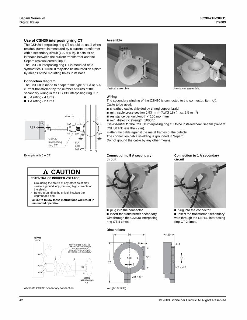
Use of CSH30 interposing ring CT AssemblyThe CSH30 interposing ring CT should be used when residual current is measured by a current transformer with a secondary circuit (1 A or 5 A). It acts as an interface between the current transformer and the Sepam residual current input.The CSH30 interposing ring CT is mounted on a symmetrical DIN rail. It may also be mounted on a plate by means of the mounting holes in its base.
E40
468
E44
717
Connection diagramThe CSH30 is made to adapt to the type of 1 A or 5 A current transformer by the number of turns of the secondary wiring in the CSH30 interposing ring CT:b 5 A rating - 4 turnsb 1 A rating - 2 turns.
Vertical assembly. Horizonal assembly.
WiringThe secondary winding of the CSH30 is connected to the connector, item .Cable to be used:b sheathed cable, shielded by tinned copper braidb min. cable cross-section 0.93 mm2 (AWG 18) (max. 2.5 mm2)b resistance per unit length < 100 mohm/mb min. dielectric strength: 1000 V.It is essential for the CSH30 interposing ring CT to be installed near Sepam (Sepam CSH30 link less than 2 m).Flatten the cable against the metal frames of the cubicle.The connection cable shielding is grounded in Sepam. Do not ground the cable by any other means.
MT
1046
8
Example with 5 A CT. Connection to 5 A secondary circuit
Connection to 1 A secondary circuit
MT
1033
1
MT
1033
3
b plug into the connectorb insert the transformer secondary wire through the CSH30 interposing ring CT 4 times.
b plug into the connectorb insert the transformer secondary wire through the CSH30 interposing ring CT 2 times.
Dimensions
MT
1046
9
Alternate CSH30 secondary connection Weight: 0.12 kg.
A
P1
P2
P1
P2
S2
S1
S1
S2
4 turns
CSH30 interposing ring CT
1819
REF
5 A core bal. CT
1 2 3
A
POTENTIAL OF INDUCED VOLTAGE
• Grounding the shield at any other point may create a ground loop, causing high currents on the shield.
• Before grounding the shield, insulate the ungrounded end.
Failure to follow these instructions will result in unintended operation.
CAUTION
A17
A18
A19
SEPAM1000+
S1
S2
CSH30INTERPOSING
CT
RECOMMENDED CABLE= 2/CSHIELDED, TWISTED, PAIR >22
AWG (<30 OHM/1000 ')1000 V DIELECTRIC STRENGTH
CONNECTED AS SHOWN BELOW
2 4.5
82
60
8
50
5
2 4.5
29
4
16

63230-216-208B1 Sepam Series 207/2003 Digital Relay
© 2003 Schneider Electric All Rights Reserved 43
Connection of ACE990 interface
MT
1034
1The ACE990 is used to match the measurement of a MV core balance CT with ratio 1/n (50 y n y 1500) with that of the Sepam residual current input.So as not to downgrade measurement accuracy, the MV core balance CT must be able to supply sufficient power. The value is given in the table opposite.
UseTo wire the ACE 990 interface correctly, it is necessary to know the following:b ratio of the core balance CT (1/n)b core balance CT powerb close approximation of the rated current Ino(1).The table opposite may be used to determine the possible choices for the connection of the ACE990 interface primary circuit to the Sepam residual current input, as well as the rated residual current setting Ino.The exact value of the rated current Ino(1) to be set is given by the following formula:Ino = k x number of core balance CT turnswith k the factor defined in the table opposite.
Example:The core balance CT used has a ratio of 1/400, 2 VA.If the current being monitored is between 0.5 A and 60 A, a close approximation of the rated current Ino may be 5 A.This value may be used to accurately measure from 0.5 A to 75 A.
Calculate the ratio : In the table opposite, find the closest value of k.5/400 = 0.0125 close value k = 0.01136.It correspoinds to core balance CTs with more than 0.1 VA of power.
The Ino value to be set is: Ino = 0.01136 x 400 = 4.5 A
This Ino value may be used to monitor a current between 0.45 A and 67.5 A.
The secondary circuit of the MV core balance CT is wired to ACE990 terminals E2 and E4.
Characteristicsb accuracy:amplitude: ±1%phase: < 2°b maximum permissible current: 20 kA 1 s (on primary of MV core balance CT with ratio 1/50 that does not saturate)b operating temperature: -5°C +55°Cb storage temperature: -25°C +70°C.
(1) current value for which the required setting range extends to between 10% and 1500% of this value, at the most.(2) parameter setting and adjustment of Ino current as a multiple of 0.1 A may be accessed from the SFT 2841 software tool or from the advanced UMI (general characteristics).
Mounted on symmetrical DIN rail, weight 640 g.
MT
1047
0
Value of k ACE990 Choice of Sepam Min. MV coreinput residual current(2) bal. CT power
0.00578 E1 – E5 ACE990 - range 1 0.1 VA0.00676 E2 – E5 ACE990 - range 1 0.1 VA0.00885 E1 – E4 ACE990 - range 1 0.1 VA0.00909 E3 – E5 ACE990 - range 1 0.1 VA0.01136 E2 – E4 ACE990 - range 1 0.1 VA0.01587 E1 – E3 ACE990 - range 1 0.1 VA0.01667 E4 – E5 ACE990 - range 1 0.1 VA0.02000 E3 – E4 ACE990 - range 1 0.1 VA0.02632 E2 – E3 ACE990 - range 1 0.1 VA0.04000 E1 – E2 ACE990 - range 1 0.2 VA
0.05780 E1 – E5 ACE990 - range 2 2.5 VA0.06757 E2 – E5 ACE990 - range 2 2.5 VA0.08850 E1 – E4 ACE990 - range 2 3.0 VA0.09091 E3 – E5 ACE990 - range 2 3.0 VA0.11364 E2 – E4 ACE990 - range 2 3.0 VA0.15873 E1 – E3 ACE990 - range 2 4.5 VA0.16667 E4 – E5 ACE990 - range 2 4.5 VA0.20000 E3 – E4 ACE990 - range 2 5.5 VA0.26316 E2 – E3 ACE990 - range 2 7.5 VA
WiringOnly one core balance CT may be connected to the ACE990 interface.The secondary circuit of the MV core balance CT is connected to 2 of the 5 ACE990 interface inputs. The core balance CT must be connected to the interface in the right direction for correct operation, in particular S1 on the MV core balance CT must be connected to the terminal with the lowest index (Ex). See Variant 4 on page 31.Cables to be used:b cable between the core balance CT and the ACE990: length less than 50 mb sheathed cable, shielded by tined copper braid between the ACE990 and Sepam: maximum length 2 mb cable cross-section between 0.93 mm2 (AWG 18) and 2.5 mm2 (AWG 13)b resistance per unit length less than 100 mW/mb minimum dielectric strength: 100 V.Connect the ACE990 connection cable shielding in the shortest manner possible (maximum 2 cm) to pin 18 of the connector .Flatten the cable from the CT to the relay against the metal frames of the cubicle. The connection cable shielding is grounded in Sepam.Do not ground the cable by any other means.
approx. Inonumber of turns
A

Sepam Series 20 63230-216-208B1Digital Relay 7/2003
© 2003 Schneider Electric All Rights Reserved44
Connection of voltage inputsB21 and B22 types
(1) This connection allows the residual voltage to be calculated.(2) CCT640 connector earthing terminal.
L1
L2
L3
2727S475927D27R59N81H81L
B21
87O2
1110O3
54O1
A
1514O4
13
1217
12
D
C
B
21
345678
communicationto communicationnetworkinterface
to optionalmodules
(2)
(1)
2727S475927D27R59N81H81L81R
B22

63230-216-208B1 Sepam Series 207/2003 Digital Relay
© 2003 Schneider Electric All Rights Reserved 45
Connection of voltage transformersThe phase and residual voltage transformer secondary circuits are connected to the CCT640 connector, item on B2X type Sepam units.
CCT640The connector contains 4 transformers which provide impedance matching and isolation between the VTs and Sepam 1000+ input circuits.Terminals B1 to B6 are intended for phase voltage measurement (1), and B7 and B8 for residual voltage measurement (case shown, not connected if obtained by the sum of the 3 phase voltages).
MT
1051
2
(1) 1, 2 or 3 VTs (case shown).
Installation of the CCT640 connectorb insert the 2 connector pins into the slots on the base unitb flatten the connector against the unit to plug it into the 9-pin SUB-D connector (principle similar to that of the MES module)b tighten the mounting screw .
Connectionb the connections are made to the screw type connectors that may be accessed on the rear of the CCT640 (item )b wiring without fitting:v 1 wire with maximum cross-section of 0.2 to 2.5 mm2 (u AWG 24-12) or 2 wires with maximum cross-section of 0.2 to 1 mm2 (u AWG 24-16)v stripped length: 8 to 10 mmb wiring with fitting: v recommended wiring with Telemecanique fitting:- DZ5CE015D for 1 wire 1.5 mm2
- DZ5CE025D for 1 wire 2.5 mm2
- AZ5DE010D for 2 wires 1 mm2
v tube length: 8.2 mmv stripped length: 8 mmb the CCT640 must be earthed (by green/yellow wire + ring lug) on the screw (safety in case the CCT640 become unplugged).
MT
1051
3
MT
1051
4
B
L1
L2
L3
B4
B5
B6
B7
B8
B3
B1
B2
CCT640
V1
V2
V3
Vo
Sepaminputs
(1)
1
2
3
4
O4
O3
O2
O145
78
1011
131415
171819
CSH
12
+ /- /
O14
O13
O12
O1123
56
89
1112
12I21
109
876
45
I24
I26I25
I22I23
I14
I13
I12
I1112
45
78
1011
2
B
1

Sepam Series 20 63230-216-208B1Digital Relay 7/2003
© 2003 Schneider Electric All Rights Reserved46
Voltage Transformer ConnectionsThe phase and residual voltage transformer secondary circuits are connected to the CCT640 connector item on B21 or B22 type Sepam Series 20 units.
Variant 1: measurement of 3 phase-to-neutral voltages (standard connection)
MT
1108
0
Phase voltage sensor parameter settingResidual voltage sensor parameter settingVoltages measured Values calculated
Measurements available Protection functions available (according to type of Sepam)
3V3V sumV1, V2, V3U21, U32, U13, Vo, Vd, Vi, f
AllAll
Variant 2: measurement of 3 phase-to-neutral voltages and residual voltage
MT
1108
1
Phase voltage sensor parameter settingResidual voltage sensor parameter settingVoltages measured Values calculated
Measurements available Protection functions available (according to type of Sepam)
3VExternal VTV1, V2, V3, VoU21, U32, U13, Vd, Vi, f
AllAll
Variant 3: measurement of 2 phase-to-phase voltages and residual voltagePhase voltage sensor parameter settingResidual voltage sensor parameter settingVoltages measured Values calculated
Measurements available Protection functions available (according to type of Sepam)
U21, U32External VTU21, U32, VoU13, V1, V2, V3, Vd, Vi, f
AllAll
Variant 4: measurement of 2 phase-to-phase voltages
MT
1108
2
Phase voltage sensor parameter settingResidual voltage sensor parameter settingVoltages measured Values calculated
Measurements unavailable Protection functions unavailable (according to type of Sepam)
U21, U32NoneU21, U32U13, Vd, Vi, f
V1, V2, V3, Vo59N
B
L1
L2
L3
B4
B5
B6
B7
B8
B3
B1
B2
CCT640
V1
V2
V3
Vo
Sepaminputs
(1)
L1
L2
L3
45678
B
321
(1)
(2)
L1
L2
L3
45678
(2)
B
321
45678
(2)
L1
L2
L3
B
321

63230-216-208B1 Sepam Series 207/2003 Digital Relay
© 2003 Schneider Electric All Rights Reserved 47
Variant 5: measurement of 1 phase-to-phase voltage and residual voltage
MT
1108
3
Phase voltage sensor parameter settingResidual voltage sensor parameter settingVoltages measured Values calculated
Measurements unavailable Protection functions unavailable (according to type of Sepam)
U21External VTU21, Vof
U32, U13, V1, V2, V3, Vd, Vi27D, 27S
Variant 6: measurement of 1 phase-to-phase voltage
Mt1
1084
Phase voltage sensor parameter settingResidual voltage sensor parameter settingVoltages measured Values calculated
Measurements unavailable Protection functions unavailable(according to type of Sepam)
U21NoneU21f
U32, U13, V1, V2, V3, Vo, Vd, Vi27D59N, 27S
1) Measurement of phase voltages with 1, 2 or 3 VTs (case shown).(2) CCT640 connector earthing terminal.
L1
L2
L3
45678
B
321
(2)
45678
L1
L2
L3
B
321
(2)
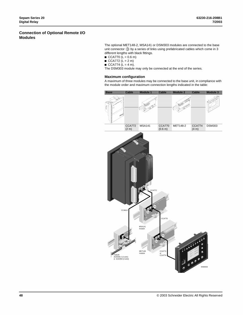
Sepam Series 20 63230-216-208B1Digital Relay 7/2003
© 2003 Schneider Electric All Rights Reserved48
Connection of Optional Remote I/O Modules
The optional MET148-2, MSA141 or DSM303 modules are connected to the base unit connector by a series of links using prefabricated cables which come in 3 different lengths with black fittings.b CCA770 (L = 0.6 m)b CCA772 (L = 2 m)b CCA774 (L = 4 m). The DSM303 module may only be connected at the end of the series.
Maximum configurationA maximum of three modules may be connected to the base unit, in compliance with the module order and maximum connection lengths indicated in the table:
Base Cable Module 1 Cable Module 2 Cable Module 3
CCA772(2 m)
MSA141 CCA770(0.6 m)
MET148-2 CCA774(4 m)
DSM303
MT
1047
1
D
MERLINGERIN
sepam 1000
MERLIN
GERIN
MERLIN
sepam 1000
MET148module
MSA141module
CCA772
CCA770
CCA772orCCA774
DSM303
CCA612
moduleACE949-2 (2-wire)or ACE959 (4-wire)
Dd
Da
reset
I on
on
0 off
clear
I1=
162A
I2=
161A
I3=
163A
Trip
ext
Io >> 51n
Io > 51n
I >> 51
I>51
D
C
Dd
Da

63230-216-208B1 Sepam Series 207/2003 Digital Relay
© 2003 Schneider Electric All Rights Reserved 49
MT
1099
6
DSM303 remote advanced UMI moduleThe DSM303 module provides the same functional features as the fixed advanced UMI.Associated with a Sepam 1000+ with a basic UMI, it may be installed on the front panel of the cubicle in the most suitable operating location.b depth of 30 mmb a single module for each Sepam 1000+ with a basic UMI, to be connected by one of the CCA772 (2 meter) or CCA774 (4 meter) prefabricated cables. This module may not be connected to Sepam 1000+ units with integrated advanced UMIs.
DSM303 remote advanced UMI module.

Sepam Series 20 63230-216-208B1Digital Relay 7/2003
© 2003 Schneider Electric All Rights Reserved50
Temperature sensor modules MET148-2
Function
PE
1006
9
The MET148-2 module may be used to connect 8 temperature sensors (RTDs) of the same type:b Pt100, Ni100 or Ni120 type RTDs, according to parameter settingb 3-wire temperature sensorsb a single module for each Sepam series 20 base unit, to be connected by one of the CCA770, CCA772 or CCA774 cords (0.6 or 2 or 4 meters))
The temperature measurement (e.g. in a transformer or motor winding) is utilized by the following protection functions:b thermal overload (to take ambient termperature into account)b temperature monitoring.
MET148-2 temperature sensor module. CharacteristicsMET148-2 module
Weight 0.2 kgAssembly On symmetrical DIN railOperating temperature -25 °C to +70 °CEnvironmental characteristics Same characteristics as Sepam base unitsRTDs Pt100 Ni100 / Ni120
Isolation from earth None NoneCurrent injected in RTD 4 mA 4 mA
DE
1021
6
Description and dimensionsTerminal block for RTDs 1 to 4.
Terminal block for RTDs 5 to 8.
RJ45 connector to connect the module to the base unit with a CCA77x cord.
RJ45 connector to link up the next remote module with a CCA77x cord (according to application).Grounding/earthing terminal.
1 Jumper for impedance matching with load resistor (Rc), to be set to:b , if the module is not the last interlinked module (default position)b Rc, if the module is the last interlinked module.
2 Jumper used to select module number, to be set to:b MET1: 1st MET148-2 module, to measure temperatures T1 to T8 (default position).
ConnectionConnection of the earthing terminalBy tinned copper braid or cable fitted with a 4 mm ring lug.
Connection of RTDs to screw-type connectorsb 1 wire with cross-section 0.2 to 2.5 mm² (u AWG 24-12)b or 2 wires with cross-section 0.2 to 1 mm² (u AWG 24-16).Recommended cross-sections according to distance:b up to 100 m ≥ 1 mm², AWG 16b up to 300 m ≥ 1.5 mm², AWG 14b up to 1 km ≥ 2.5 mm², AWG 12.
Wriring precautionsb it is preferable to use shielded cablesThe use of unshielded cables may cause measurement errors, which vary in degree on the level of surrounding electromagnetic disturbanceb only connect the shielding at the MET148-2 end, in the shortest manner possible, to the corresponding terminals of connectors and b do not connect the shielding at the RTD end.
Accuracy derating according to wiringThe error ∆t is proportional to the length of the cable and inversely proportional to the cable cross-section:
b ±2.1 °C/km for 0.93 mm² cross-sectionb ±1 °C/km for 1.92 mm² cross-section.
(1) 70 mm with CCA77x cable connected.
DE
1021
7
A
B
Da
Dd
t
Rc
A B
∆t ° C( ) 2L km( )
S mm2( )----------------------×=

63230-216-208B1 Sepam Series 207/2003 Digital Relay
© 2003 Schneider Electric All Rights Reserved 51
Analog output module MSA141
Function
PE
1007
0
The MSA141 module converts one of the Sepam measurements into an analog signal:b selection of the measurement to be converted by parameter settingb 0-10 mA, 4-20 mA, 0-20 mA analog signal according to parameter settingb scaling of the analog signal by setting minimum and maximum values of the converted measurement.Example: the setting used to have phase current 1 as a 0-10 mA analog output with a dynamic range of 0 to 300 A is:v minimum value = 0v maximum value = 3000b a single module for each Sepam base unit, to be connected by one of the CCA770, CCA772 or CCA774 cords (0.6 or 2 or 4 meters).
The analog output may also be remotely managed via the Modbus communication network.
MSA141 analog output module.
CharacteristicsMSA141 module
Weight 0.2 kgAssembly On symmetrical DIN railOperating temperature -25°C to +70°CEnvironmental characteristics Same characteristics as Sepam base unitsAnalog output
Current 4-20 mA, 0-20 mA, 0-10 mAScaling (no data input checking) Minimum value
Maximum valueLoad impedance < 600 Ω (wiring included)Accuracy 0.5 %Measurements available Unit Series 20
Phase and residual currents 0.1 A bPhase-to-neutral and phase-to-phase voltages
1 V b
Frequency 0.01 Hz bThermal capacity used 1% bTemperatures 1°C bRemote setting via communication link b
DE
1021
8 Description and dimensionsTerminal block for analog output.
RJ45 connector to connect the module to the base unit with a CCA77x cord.
RJ45 connector to link up the next remote module with a CCA77x cord (according to application).Grounding/earthing terminal.
1 Jumper for impedance matching with load resistor (Rc), to be set to:b , if the module is not the last interlinked module (default position)b Rc, if the module is the last interlinked module.
ConnectionEarthing terminal connectionBy tinned copper braid or cable fitted with a 4 mm ring lug.
Connection of analog output to screw-type connector b 1 wire with cross-section 0.2 to 2.5 mm² (u AWG 24-12)b or 2 wires with cross-section 0.2 to 1 mm² (u AWG 24-16).
Wiring precautionsb it is preferable to use shielded cablesb use tinned copper braid to connect the shielding at least at the MSA141 end.
(1) 70 mm with CCA77x cord connected.
DE
1021
9
A
Da
Dd
t
Rc

Sepam Series 20 63230-216-208B1Digital Relay 7/2003
© 2003 Schneider Electric All Rights Reserved52
Communication interface module These modules are used for simple, dependable commissioning of the RS 485 link according to 2 connection topologies:
• 2-wire network with the ACE 949-2 module
• 4-wire network with the ACE 959 module
The RS 485 communication interfaces are supplied, via the network cable, by a single accessory that may be used to connect up to 25 units according to the chart below:
• These values are obtained with a standard AWG 24 2-pair cable with a resistance load per unit length of 78 1/2 Ω / km.
• Tolerance with distributed power supply: ± 10%.
• Values multiplied by 3 with a maximum of 1300 m with a specific cable; reference FILECA F2644-1; Schneider-approved.
For additional communications information, see “Communications Interface Wiring” on page 58. For information on the commissioning of the RS 485 network and the characteristics of the recommended cables, refer to “RS 485 Network Connection Guide“ PCRED399074EN.
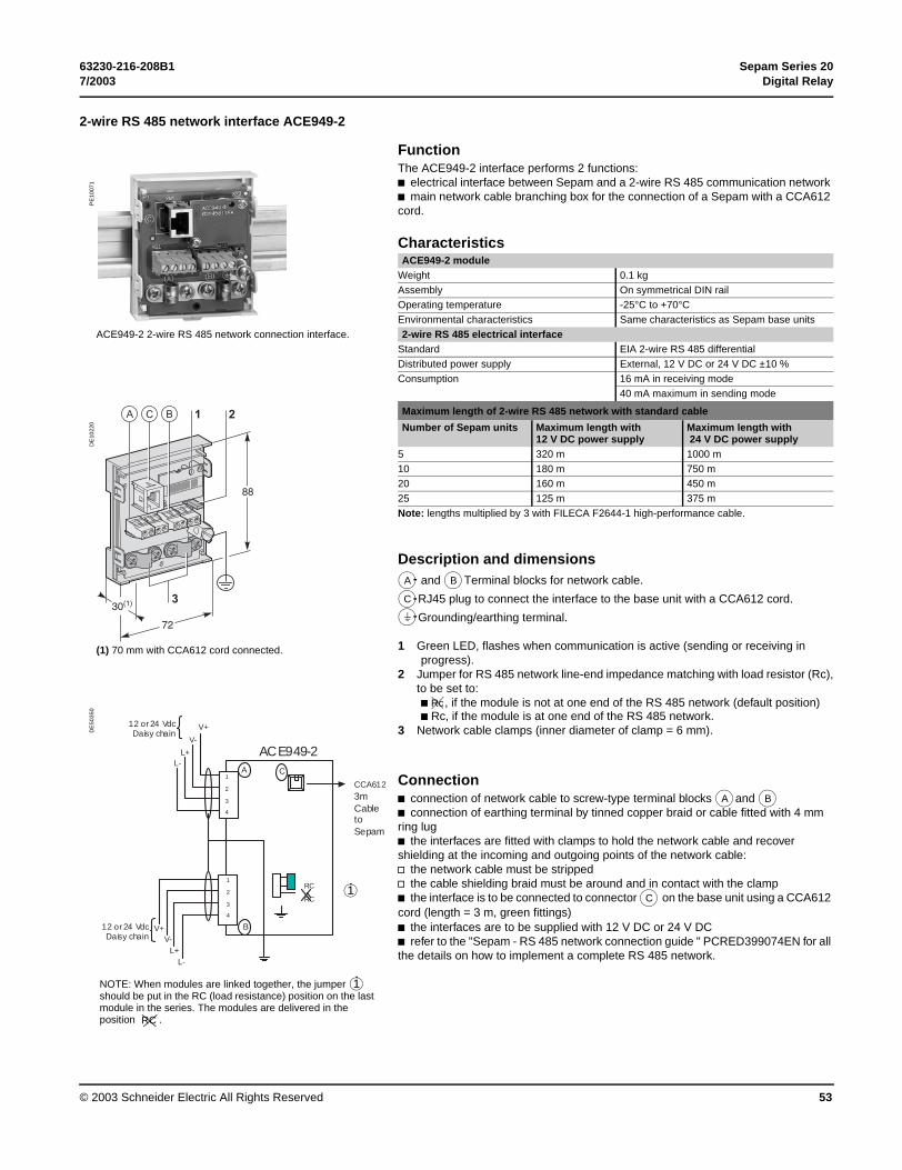
63230-216-208B1 Sepam Series 207/2003 Digital Relay
© 2003 Schneider Electric All Rights Reserved 53
2-wire RS 485 network interface ACE949-2
Function
PE
1007
1
The ACE949-2 interface performs 2 functions:b electrical interface between Sepam and a 2-wire RS 485 communication network b main network cable branching box for the connection of a Sepam with a CCA612 cord.
CharacteristicsACE949-2 module
Weight 0.1 kgAssembly On symmetrical DIN railOperating temperature -25°C to +70°CEnvironmental characteristics Same characteristics as Sepam base units
ACE949-2 2-wire RS 485 network connection interface. 2-wire RS 485 electrical interfaceStandard EIA 2-wire RS 485 differentialDistributed power supply External, 12 V DC or 24 V DC ±10 %Consumption 16 mA in receiving mode
40 mA maximum in sending mode
DE
1022
0
Maximum length of 2-wire RS 485 network with standard cable
Number of Sepam units Maximum length with 12 V DC power supply
Maximum length with 24 V DC power supply
5 320 m 1000 m10 180 m 750 m20 160 m 450 m25 125 m 375 mNote: lengths multiplied by 3 with FILECA F2644-1 high-performance cable.
Description and dimensionsand Terminal blocks for network cable.
RJ45 plug to connect the interface to the base unit with a CCA612 cord.
Grounding/earthing terminal.
1 Green LED, flashes when communication is active (sending or receiving in progress).
2 Jumper for RS 485 network line-end impedance matching with load resistor (Rc),to be set to:b , if the module is not at one end of the RS 485 network (default position)b Rc, if the module is at one end of the RS 485 network.
3 Network cable clamps (inner diameter of clamp = 6 mm).
(1) 70 mm with CCA612 cord connected.
DE
5035
0
Connectionb connection of network cable to screw-type terminal blocks and b connection of earthing terminal by tinned copper braid or cable fitted with 4 mm ring lugb the interfaces are fitted with clamps to hold the network cable and recover shielding at the incoming and outgoing points of the network cable: v the network cable must be stripped v the cable shielding braid must be around and in contact with the clampb the interface is to be connected to connector on the base unit using a CCA612 cord (length = 3 m, green fittings)b the interfaces are to be supplied with 12 V DC or 24 V DCb refer to the "Sepam - RS 485 network connection guide " PCRED399074EN for all the details on how to implement a complete RS 485 network.
A B
C
t
Rc
RC
RC
A
B
C1
2
3
4
1
2
3
4
ACE949-2
CCA6123m Cable to Sepam
12 or 24 Vdc Daisy chain
12 or 24 Vdc Daisy chain
V+
V-
L+L-
V+V-
L+L-
NOTE: When modules are linked together, the jumper should be put in the RC (load resistance) position on the last module in the series. The modules are delivered in the position .
1
RC
1
A B
C

Sepam Series 20 63230-216-208B1Digital Relay 7/2003
© 2003 Schneider Electric All Rights Reserved54
4-wire RS 485 network interface ACE959
Function
PE
1007
2
The ACE959 interface performs 2 functions:b electrical interface between Sepam and a 4-wire RS 485 communication network b main network cable branching box for the connection of a Sepam with a CCA612 cord.
CharacteristicsACE959 module
Weight 0.2 kgAssembly On symmetrical DIN railOperating temperature -25°C to +70°C
ACE959 4-wire RS 485 network connection interface. Environmental characteristics Same characteristics as Sepam base units4-wire RS 485 electrical interface
Standard EIA 4-wire RS 485 differentialDistributed power supply External, 12 V DC or 24 V DC ±10 %
DE
1022
2
Consumption 16 mA in receiving mode40 mA maximum in sending mode
Maximum length of 4-wire RS 485 network with standard cable
Number of Sepam units Maximum length with 12 V DC power supply
Maximum length with 24 V DC power supply
5 320 m 1000 m10 180 m 750 m20 160 m 450 m25 125 m 375 mNote: lengths multiplied by 3 with FILECA F3644-1 high-performance cable.
Description and dimensionsand Terminal blocks for network cable.
RJ45 plug to connect the interface to the base unit with a CCA612 cord.
Terminal block for a separate auxiliary power supply (12 V DC or 24 V DC).Grounding/earthing terminal.
1 Green LED, flashes when communication is active (sending or receiving in progress).
2 Jumper for RS 485 network line-end impedance matching with load resistor (Rc),to be set to:b , if the module is not at one end of the RS 485 network (default position)b Rc, if the module is at one end of the RS 485 network.
3 Network cable clamps (inner diameter of clamp = 6 mm).
(1) 70 mm with CCA612 cord connected.
DE
5035
1
A B
C
Dt
Rc

63230-216-208B1 Sepam Series 207/2003 Digital Relay
© 2003 Schneider Electric All Rights Reserved 55
DE
5035
1
Connectionb connection of network cable to screw-type terminal blocks and b connection of earthing terminal by tinned copper braid or cable fitted with 4 mm ring lugb the interfaces are fitted with clamps to hold the network cable and recover shielding at the incoming and outgoing points of the network cable: v the network cable must be stripped v the cable shielding braid must be around and in contact with the clampb the interface is to be connected to connector on the base unit using a CCA612 cord (length = 3 m, green fittings)b the interfaces are to be supplied with 12 V DC or 24 V DCb the ACE959 can be connected to a separate distributed power supply (not included in shielded cable). Terminal block is used to connect the distributed power supply moduleb refer to the "Sepam - RS 485 network connection guide" PCRED399074EN for all the details on how to implement a complete RS 485 network.
(1) Distributed power supply with separate wiring or included in the shielded cord (3 pairs).(2) Terminal block for connection of the module that provides the distributed power supply.(3) Use a braid or cable equipped with a 4 mm ring lug.(4) When modules are linked together without DSM303, the jumper (4) should be put in the RC (load resistance) position on the last module in the series (MET148 or MSA141). The modules are delivered in the position .
RC
RC
RC
RC
A
D
B
C
TX
RX
1
2
3
4
5
6
1
2
V-
V+
ACE959
CCA6123m Cable to Sepam
12 or 24 Vdc ext.power source
12 or 24 Vdc Daisy chain
12 or 24 Vdc Daisy chain
1
Tx+
Tx-Rx+
Rx-
V-V+
Tx+
Tx-Rx+
Rx-V-
V+
(2) (4)
(4)Rx+, Rx- : receiving Sepam
(eq IN+, IN-)Tx+, Tx- : sending Sepam
(eq OUT+, OUT-)
A B
C
D
RC

Sepam Series 20 63230-216-208B1Digital Relay 7/2003
© 2003 Schneider Electric All Rights Reserved56
Fiber optic interface ACE937
Function
PE
1007
3
The ACE937 interface is used to connect Sepam to a fiber optic communication star system.This remote module is connected to the Sepam base unit by a CCA612 cord.
CharacteristicsACE937 module
Weight 0.1 kgAssembly On symmetrical DIN railPower supply Supplied by SepamOperating temperature -25°C to +70°CEnvironmental characteristics Same characteristics as Sepam base units
ACE937 fiber optic connection interface. Fiber optic interfaceWavelength 820 nm (infra-red)Type of connector STFiber type Multimode glassFiber optic diameter (µm)
Numerical aperture (NA)
Maximum attenuation (dBm/km)
Minimum optical power available (dBm)
Maximum length of fiber (m)
50/125 0.2 2.7 5.6 70062.5/125 0.275 3.2 9.4 1800100/140 0.3 4 14.9 2800200 (HCS) 0.37 6 19.2 2600
Maximum length calculated with:b minimum optical power availableb maximum fiber attenuationb losses in 2 ST connectors: 0.6 dBmb optical power margin: 3 dBm (according to IEC60870 standard).
Example for a 62.5/125 µm fiberLmax = (9.4 - 3 -0.6) / 3.2 = 1.8 km.
DE
1022
4
Description and dimensionsRJ 45 plug to connect the interface to the base unit with a CCA612 cord.
1 Green LED, flashes when communication is active (sending or receiving in progress)..
2 Rx, female ST type connector (Sepam receiving).3 Tx, female ST type connector (Sepam sending).
(1) 70 mm with CCA612 cord connected.
Connectionb the sending and receiving fiber optics fibers must be equipped with male ST type connectorsb fiber optics screw-locked to Rx and Tx connectors
b the interface is to be connected to connector on the base unit using a CCA612 cord (length = 3 m, green fittings)
DE
1022
5
C
C

63230-216-208B1 Sepam Series 207/2003 Digital Relay
© 2003 Schneider Electric All Rights Reserved 57
IMPLEMENTATION OF THE MODBUS NETWORK
Communications Wiring
Biasing the Communications Link To ensure reliable communications, you must bias the POWERLOGIC communications link (if biasing is not in the system master nor an interfacing RS232/485 converter). Use a Multipoint Communications Adapter (MCA-485) biasing device. Place the adapter between the first device on the link and the communications port of the PC. The illustration below shows installation of the adapter when the first device on the link is a Sepam 1000+ relay.
One set of biasing resistors is required per daisy chain. On the Black Box converter IC109A-R2, these can be activated by a switch. Other converters
A set of adapted accessories is used for fast, dependable implementation of the communication network from both the electrical and environmental (electromagnetic compatibility) viewpoints.
➀ Network connection interface, to be supplied by 12 V DC or 24 V DC distributed power supplyb ACE949-2 for 2-wire RS 485 networksb or ACE959 for 4-wire RS 485 networks.➁ CCA612 cable for connection of the interface to the C port of the Sepam base unit.➂ Interface for connection of the RS 485 network to the Modbus master, with distributed power supply to the ACE949-2 interfaces and polarization/termination of the communication linkb ACE909-2, 2-wire RS 485 / RS 232 converterb or ACE919CA (110 V AC or 220 V AC) 2-wire RS 485/2-wire RS 485 interfaceb or ACE919CC (24 V DC or 48 V DC) 2-wire RS 485/2-wire RS 485 interface.➃ Modbus network cableb for 2-wire RS 485 network: two shielded twisted pairs(1 RS 485 pair, 1 pair for power suuply)b for 4-wire RS 485 network: three shielded twisted pairs(2 RS 485 pairs, 1 pair for power supply)b with tinned copper braiding shielding, coverage: > 65%b characteristic impedance: 120 Ωb gauge: AWG 24b resistance per unit length: < 100 Ω/kmb capacitance between conductors: < 60 pF/mb capacitance between conductor and shielding: < 100 pF/mb maximum length: 1300 m.
Example of standard cable (for 2-wire RS 485 network):b supplier: BELDEN reference: 9842 or 8723b supplier: FILOTEX reference: FMA-2PS.High-performance cable (for 2-wire RS 485 network):b supplier: FILECA reference: F2644-1 (cable distributed by Schneider Electric in 60 m strands, reference CCR301).
For more information, refer to the "Sepam - RS 485 network connection guide" PCRED399074EN.
2
1
MERLIN GERIN MERLIN GERIN MERLIN GERIN
3
4
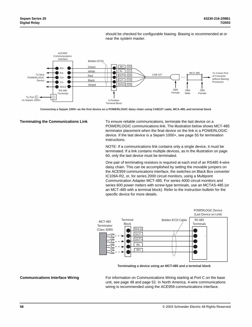
Sepam Series 20 63230-216-208B1Digital Relay 7/2003
© 2003 Schneider Electric All Rights Reserved58
should be checked for configurable biasing. Biasing is recommended at or near the system master.
Terminating the Communications Link To ensure reliable communications, terminate the last device on a POWERLOGIC communications link. The illustration below shows MCT-485 terminator placement when the final device on the link is a POWERLOGIC device. If the last device is a Sepam 1000+, see page 55 for termination instructions.
NOTE: If a communications link contains only a single device, it must be terminated. If a link contains multiple devices, as in the illustration on page 60, only the last device must be terminated.
One pair of terminating resistors is required at each end of an RS485 4-wire daisy chain. This can be accomplished by setting the movable jumpers on the ACE959 communications interface, the switches on Black Box converter IC109A-R2, or, for series 2000 circuit monitors, using a Multipoint Communication Adapter MCT-485. For series 4000 circuit monitors and series 600 power meters with screw-type terminals, use an MCTAS-485 (or an MCT-485 with a terminal block). Refer to the instruction bulletin for the specific device for more details.
Communications Interface Wiring For information on Communications Wiring starting at Port C on the base unit, see page 48 and page 52. In North America, 4-wire communications wiring is recommended using the ACE959 communications interface.
TX–
TX+
RX–
RX+
SHLD
21
20
22
23
24
IN+
SHLD
OUT–
OUT+
IN–
Green
Shield
Black
Red
WhiteTo Next
POWERLOGICDevice
5-PositionTerminal Block
To Comm Portof Converterwithout BiasingProvisions
DB9Female
DB9Male
DB9Female
RS-485Terminals
CTo Port Con Sepam 1000+
ACE959 Communications
Interface
Connecting a Sepam 1000+ as the first device on a POWERLOGIC daisy chain using CAB107 cable, MCA-485, and terminal block
CAB-107
Belden 8723
MCA-485
IN+
-
SHLD
OUT-
OUT+
IN-
MCT-485Terminator(Class 3090)
TerminalBlock
POWERLOGIC Device(Last Device on Link)
RS-485Terminals
Terminating a device using an MCT-485 and a terminal block
Belden 8723 Cable

63230-216-208B1 Sepam Series 207/2003 Digital Relay
© 2003 Schneider Electric All Rights Reserved 59
This interface requires external 12/24 Vdc control power. See “Communication interface module” on page 52 for information on wiring the ACE959.
The illustrations on the following pages show typical communications network connections.
Figure 10: Typical Serial Communications Application
B
TX+
A
RX-
TX-
V-
V+
RX+
TerminatorMCT-485
CM-4000Circuit Monitor
RX+
RX–
TX+
TX–
20
21
22
23
24
Green
White
Red
Black
PM-600Power Meter
RX+ (Green)
To Next Sepam 1000+
TX+ (Red)
TX– (Black)
ACE959Communications
Interface
CAB107(DB9 Female)
CAB108NL(DB9 Male)
C
To 24 Vdc Reliable Source
To Next Sepam 1000+
Gre
en
Whi
te
Red
Blac
k
TXB RXB
RXATXA
RS232 Port
TR
BR
DB25
DB9
BlackBoxIC109A-R2RS232/485Converter
RS-232 Port
StandardRS232 Cable
RX– (White)
In+
In–
Out+
Out–
Shld
To Port COn Sepam 1000+
2 ft. (0.6 m) max.
POWERLOGICSystem Manager
Software (SMS)
CCA612
5
4
3
2
1
See "Shield and Grounding" note below
N/C5
4
3
2
1
5
4
3
2
1
6 6
2 1
V+ V-
D
Notes:
• Shield and Grounding— The shield is broken between two grounded shield termination points. Leave the shield intact from source until just before next shield ground. See Figure 11 on page 60 for more information.
• BR=Biasing Resistor. Also known as Polarizing Resistor (RP).
• TR= Terminating Resistor (also known as RC).
• Tie-back and tape shield are not connected at this end.

Sepam Series 20 63230-216-208B1Digital Relay 7/2003
© 2003 Schneider Electric All Rights Reserved60
Cable Pinouts
Cable pinouts for CAB-107 and CAB-108 cables are shown below.
Figure 11: Network Daisy Chain Practices (including Shield Grounding)
Sepam1000+
No. 2
Sepam1000+No. 25
ACE959
RS232/RS485Converter
& Power Supply
TR TR BR
ACE959ACE959
Sepam1000+
No. 1
TR TRRS232
CCA612CCA612 CCA612
SystemPC
110 Vac
Notes: RS485 cable is 4-wire plus shield. 2-wire power (24 Vdc) is also required. Recommended cable: Belden 9841 (1 pair-signal) Belden 9842 or 8723 (2 pair-signal) Belden 8760 (1 pair #18-power) or 8719 (1 pair #16-power) Fileca F3644-1 (2 pair signal/1 pair power) Shield is broken between two grounded shield termination points (typical). Leave the shield intact from source until just before next shield ground. Up to 25 Sepam 1000+ relays (maximum) on daisy chain. TR=Terminating Resistor Two TRs are required at each end of an RS485 4-wire diasy chain (can be accomplished by setting the movable jumpers on Sepam module ACE959, the switches on Black Box converter IC109A-R2, or, for series 2000 circuit monitors, using a Multipoint Communications Adapter MCT-485). For series 4000 circuit monitors and series 600 power meters with a screw-type terminal block, use an MCTAS-485 (or an MCT-485 with a terminal block). Refer to the device instruction bulletin for more details. BR= Biasing Resistor One BR set required per daisy chain (accomplish by setting switch on Black Box converter IC109A-R2; other converters should be checked for configurable biasing [recommended at or near system master]). One recommended RS232/RS485 Converter is Black Box IC109A-R2 (power supply separate).
Shield *N/C ShieldShield
RS485
RS485
*N/C*N/C
*Tie-back and tape shield are not connected at this end.
Equipment #1 Equipment #2 Equipment #25

63230-216-208B1 Sepam Series 207/2003 Digital Relay
© 2003 Schneider Electric All Rights Reserved 61
Remote Operation via Ethernet LAN The illustration below shows a typical POWERLOGIC Power Monitoring and Control System using Ethernet as the high-speed backbone to collect information from various devices and to allow the data to be shared by multiple users on different PCs.
PC with NetworkInterface Card
PC with NetworkInterface Card
Static IP Address101.101.228.40
Cat. 5 UTP Cable328 ft (100 m) max.
10BaseTEthernet Hub
RJ-45 Connector
10BaseTEthernet Hub
Cat. 5 UTP Cable328 ft (100 m) max.
Circuit MonitorCM4000with ECC
Static IP Address101.101.228.30
Windows NT or 98 SMS1000 Client
Cat. 5 UTP Cable328 ft (100 m) max
EthernetCrossoverCable
2- or 4-Wire RS-485
DC150 Gatewayto Internal Bus
Cat. 5 UTP Cable328 ft (100 m) max.
CM4000Circuit Monitor
with ECCStatic IP Address101.101.228.29
2- or 4-Wire RS-485
Windows NTSMS 3000 Server
RJ-45 ConnectorRJ
Terminator
POWERLOGIC System DevicesIncluding Sepam 1000+ Relays
POWERLOGIC System DevicesIncluding Sepam 1000+ Relays
10Base T Star Topology with Ethernet Communications Card (ECC)installed in Circuit Monitor Series 4000

Sepam Series 20 63230-216-208B1Digital Relay 7/2003
© 2003 Schneider Electric All Rights Reserved62
Software The setting/operation software kit (number SFT2841) includes parameter setting and operating software as well as fault waveform recovery software SFT2826. A cable for connecting a computer to a basic or an advanced UMI is also included.
In addition to the basic and advanced UMIs, you may see references in this document to an "expert UMI." The term "expert UMI" refers to a basic or an advanced UMI used in conjunction with SFT2841 software.
POWERLOGIC System Manager Software
POWERLOGIC System Manager Software can also be used with the Sepam Series 20. For information, refer to Sepam 1000+ device type in a POWERLOGIC system, document number 63230-218-200/A1.

63230-216-208B1 Sepam Series 207/2003 Digital Relay
© 2003 Schneider Electric All Rights Reserved 63
SECTION 4— OPERATION
USER MACHINE INTERFACES
Two different levels of user machine interface (UMI) are offered on the front panel of Sepam:b basic UMI, with signal LEDs, for installations operated via a remote system with no need for local operationb advanced UMI, with keypad and graphic LCD display, giving access to all the information necessary for local operation and Sepam parameter setting.
The UMI on the front panel of Sepam may be complemented by an expert UMI comprising the SFT2841 PC software tool, which may be used for all Sepam parameter setting, local operation and customization functions.
The expert UMI comes as a kit, the “SFT2841” kit, which includes:b a CD-ROM, withv SFT2841 setting and operation softwarev SFT2826 fault recording file display softwareb CCA783 cable, for connection between the PC and the serial port on the front panel of Sepam.
MT
1080
2
CCA783
Sepam1000+base unit with fixed advanced UMI
MERLINGERIN
sepam
I1=
162A
I2=
161A
I3=
163A
reset
I on
on
0 off
clear
Trip
ext
Io >> 51n
Io > 51n
I >> 51
I > 51
SFT2841parameter settingand operating software
SFT2826 disturbance recording display software

Sepam Series 20 63230-216-208B1Digital Relay 7/2003
© 2003 Schneider Electric All Rights Reserved64
EXPERT UMI (SFT2841)
The expert UMI is available (as a complement to the basic or advanced UMI integrated in the product) on the screen of a PC equipped with the SFT2841 software tool and connected to the RS 232 port on the front panel of Sepam (run in a Windows ≥ V95 or NT environment). All the data used for the same task are grouped together in the same screen to facilitate operation. Menus and icons are used for fast, direct access to the required information.
Current operation b display of all metering and operation datab display of alarm messages with the time of appearance (date, hour, mn, s, ms) [more than advanced UMI] (2)
b updating time and date when connected to relay (2)
b display of diagnosis data such as: tripping current, number of switchgear operations and cumulative breaking currentb display of all the protection and parameter settingsb display of the logic status of inputs, outputs and signal lamps.This UMI is the solution suited to occasional local operation, for demanding personnel who require fast access to all the information.
Parameter and protection setting (1) b display and setting of all the parameters of each protection function in the same pageb program logic parameter setting, parameter setting of general installation and Sepam datab input data may be prepared ahead of time and transferred into the corresponding Sepam units in a single operation (downloading function). (2)
Main functions performed by SFT2841:b changing of passwords (2)
b entry of general characteristics (ratings, integration period, …)b entry of protection settingsb changing of program logic assignments (outputs and LEDs configuration)b editing alarm LED labels (2)
b enabling/disabling of functionsb saving of files (2).
Saving b protection and parameter setting data may be saved (2)
b printing of reports is possible as well. (2)
This UMI may also be used to recover fault recording files (2) and provide graphic display using the SFT2826 software tool.
Operating assistanceAccess from all the screens to a help section which contains all the technical data required for Sepam installation and use.
Mt1
1190
Example of a measurement display screen.
MT
1119
1
Example of a protection setting screen.
(1) Modes accessed via 2 levels of passwords (protection setting level, parameter setting level).(2) These features are beyond the scope of the advanced UMI.

63230-216-208B1 Sepam Series 207/2003 Digital Relay
© 2003 Schneider Electric All Rights Reserved 65
SFT2841 General screen organization
A Sepam document is displayed on the screen via a graphic interface that has the conventional Windows features. All the SFT2841 software screens are set up in the same way, i.e.:b : title bar, with:v name of the application (SFT2841)v identification of the Sepam document displayedv window manipulation handlesb : menu bar, to access all the SFT2841 software functions (unavailable functions are dimmed)b : toolbar, a group of contextual icons for quick access to the main functions (also accessed via the menu bar)b : work zone available to the user, presented in the form of tab boxesb : status bar, with the following information relating to the active document:v alarm onv identification of the connection windowv SFT2841 operating mode, connected or not connected,v type of Sepamv Sepam editing identificationv identification levelv Sepam operating modev PC date and time.
MT
1119
2
Example of Sepam configuration screen.
MT
1119
3
Guided navigationA guided navigation mode is proposed to make it easier to enter all of the Sepam parameter and protection settings. It allows users to go through all the data input screens in the natural order.The sequencing of the screens in guided mode is controlled by clicking on 2 icons in the toolbar :b : to go back to the previous screenb : to go to the next screen.
The screens are linked up in the following order:1. Sepam hardware configuration2. Program logic3. General characteristics4. Setting screens for the protection functions available, according to the type of Sepam5. Various tabs of the control matrix
Example of general characteristics screen.
On-line helpThe operator may look up on-line help at any time via the "?" command in the menu bar.To use the on-line help, a browser such as Netscape Navigator or Internet Explorer MS is required.
A
B
C
D
E
A
B
C
D
E
C

Sepam Series 20 63230-216-208B1Digital Relay 7/2003
© 2003 Schneider Electric All Rights Reserved66
SFT2841 Use of the software
“Not connected to Sepam” mode “Connected to Sepam” modeSepam parameter and protection settingThe parameter and protection setting of a Sepam using SFT2841 consists of preparing the Sepam file containing all the characteristics that are specific to the application, a file that is then downloaded into Sepam at the time of commissioning.Operating mode:b create a Sepam file for the type of Sepam to be set up. (The newly created file contains the Sepam factory-set parameter and protection settings)b modify the Sepam general settings and protection function settings:v all the data relating to the same function are grouped together in the same screenv it is advisable to enter all the parameters and protection settings in the natural order of the screens proposed by the guided navigation mode. See preceding page.
Entry of parameter and protection settings:b the parameter and protection setting input fields are suited to the type of value:v choice buttons (for example, 50 Hz/60 Hz [See page 65.])v numerical value input fieldsv dialogue box (Combo box)b the user must "Apply" or "Cancel" the new values entered before going on to the following screenb the consistency of the new values applied is checked:v an explicit message identifies inconsistent values and specifies the authorized valuesv values that have become inconsistent following a parameter modification are replaced by “****” and must be corrected.
PrecautionWhen using a laptop, discharge to a grounded metal frame before physically connecting the CCA783 cable (supplied with the SFT2841 kit).
Plugging into Sepamb plugging of the 9-pin connector (SUB-D type) into one of the PC communication ports. Configuration of the PC communication port via the “Communication port” function in the “Options” menu b plugging of the 6-pin connector into the connector (round minidin type) situated behind the blanking plate on the front panel of Sepam or the DSM303 module.
Connection to Sepam2 possibilities for setting up the connection between SFT2841 and Sepam:b “Connection” function in the “File” menub choice of “connect to the Sepam” at the start-up of SFT2841.Once the connection with Sepam has been established, “Connected” appears in the status bar, and the Sepam connection window may be accessed in the work zone.
User identificationThe window intended for the entry of the 4-digit password is activated:b via the “Passwords” tabb via the “Identification” function in the “Sepam” menub via the “Identification” icon .The "Return to Operating mode" function in the “Passwords” tab removes access rights to parameter and protection setting mode.
Downloading of parameters and protection settingsParameter and protection setting files may only be downloaded in the connected Sepam in Parameter setting mode. Once the connection has been established, the procedure for downloading a parameter and protection setting file is as follows:b activate the “Download Sepam” function in the “Sepam” menub select the file(*.rpg) which contains the data to be downloaded.
Return to factory settingsThis operation is only possible in Parameter setting mode, via the “Sepam” menu. All of the Sepam general characteristics, protection settings and the control matrix go back to the default values.
Uploading of parameter and protection settingsThe connected Sepam parameter and protection setting file may only be uploaded in Operating mode. Once the connection has been established, the procedure for uploading a parameter and protection setting file is as follows:b activate the “Upload Sepam” function in the “Sepam” menub select the *.rpg file that is to contain the uploaded datab acknowledge the end of operation report.
Local operation of SepamConnected to Sepam, SFT2841 offers all the local operating functions available in the advanced UMI screen, plus the following functions:b setting of Sepam internal clock, via the “general characteristics” tabb implementation of the disturbance recording function, via the “Fault recording” menu “OPG”: validation/inhibition of the function, recovery of Sepam files, start-up of SFT2826b consultation of the history of the last 64 Sepam alarms, with time-taggingb access to Sepam diagnostic data, in the “Sepam” tab box, included in “Sepam diagnosis”b in Parameter setting mode, the switchgear diagnostic values may be modified: operation counter, cumulative breaking current to reset the values after a change of breaking device.
HAZARD OF UNINTENDED OPERATION
A new setting is not applied to the Sepam 1000+ configuration until you press the enter button to store the new setting. If the “CHECK SETTINGS” message appears when you press enter, the new setting conflicts with other settings.
Failure to do so could result in unintended operation of the trip output contacts.
CAUTION
6-Pin DIN (Male)
1 (Rx)
2 (Tx)
3 (Gnd)
6-Pin DIN (Male)
1 (Rx)
2 (Tx)
3 (Gnd)
DB-9 (Female)
3 (Tx)
2 (Rx)
5 (Gnd)
DB-9 (Female)
3 (Tx)
2 (Rx)
5 (Gnd)
CCA783 Cable pinouts

63230-216-208B1 Sepam Series 207/2003 Digital Relay
© 2003 Schneider Electric All Rights Reserved 67
BASIC UMI ON RELAY
This UMI includes:b 2 signal lamps indicating Sepam operating status:v green "on" indicator: device onv red "wrench" indicator: device unavailable (initialization phase or equipment malfunction)b 9 parameterizable yellow signal lamps, fitted with a standard label (with SFT2841, a customized label can be printed on a laser printer)b "reset" button for clearing and resetting alarms and tripsb 1 connection port for the RS 232 link with the PC (CCA783 cable), the connector is protected by a sliding cover (blanking cover).
MT
1027
6
Advanced UMI on Relay or Remote
MT
1027
7In addition to the basic UMI functions, this version provides:b a "graphic" LCD display for the display of measurements, parameter/protection settings and alarm and operating messages.The number of lines, size of characters and symbols are in accordance with the screens and language versions.The LCD display is back-lit when the user presses a key.b a 9-key keypad with 2 operating modes:
White keys for current operation:display of measurements,display of switchgear and network diagnosis data,display of alarm messages, resetting,acknowledgment and clearing of alarms.
Blue keys activated in parameter and protection setting mode:
access to protection settings,access to Sepam parameter setting,used to enter the 2 passwords required to change
protection and parameter settings.The "↵ , , " ( , , ) keys are used to browse through the menus and to scroll and accept the values displayed.
"lamp test" key:switching on sequence of all the signal lamps.
10
reset
0 off I on TripextI >> 51I>51on Io >> 51NIo > 51N
reset
I onextIo >> 51NIo > 51NI> > 51I>51on 0 off
clear
I1 = 162AI2 = 161AI3 = 163A
Trip
1
2
3
45678910
12345
789
r r
4 5 6
6

Sepam Series 20 63230-216-208B1Digital Relay 7/2003
© 2003 Schneider Electric All Rights Reserved68
ADVANCED UMI
Access Levels of Use
MT
1080
8There are 3 levels of use:b operator level: used to access all the screens in read mode and does not require any passwordsb relay technician level: requires the entry of the first password ( key), allows protection setting ( key)b relay engineer level: requires the entry of the second password ( key), allows modification of the general settings as well ( key). Only relay engineer level may modify the passwords. The passwords have 4 digits.
Access to measured and calculated data (operator level)
Example: measurement loop
MT
1088
5The measurements and parameters may be accessed using the metering, diagnosis, status and protection keys. They are arranged in a series of screens as shown in the diagram opposite.b the data are split up by category in 4 menus, associated with the following 4 keys:v key: measurementsv key: switchgear diagnosis and additional measurementsv key: general settings
v key: protection settingsv when the user presses a key, the system moves on to the next screen in the loop. When a screen includes more than 4 lines, the user moves about in the screen via the cursor keys ( , ).
reset
I onon 0 off
clear
passwords
apply cancel
TripextI >> 51I>51 Io >> 51NIo > 51N
Measurements bar graphs
clear
Overcurrent
Average I
Temperatures1 to 4temperature sensors
clear
Measurements numerical valuesI rms
Iobar graph
Temperatures5 to 8temperature sensors

63230-216-208B1 Sepam Series 207/2003 Digital Relay
© 2003 Schneider Electric All Rights Reserved 69
White keys for current operation
key
MT
1028
3
The "metering" key is used to display the variables measured by Sepam.
key
MT
1111
7
The “diagnosis” key provides access to diagnostic data on the circuit breaker or contactor and additional measurements, to facilitate fault analysis.
resetclear
I1 = 162AI2 = 161AI3 = 163A
I onextIo >> 51NIo > 51NI> > 51I>51on 0 off Trip
reset
I onon 0 off
clear
Trip circuit: OK
TripextI >> 51I>51 Io >> 51NIo > 51N
:
arg
Op. Nb. 123
Op. time 57 ms
Ch time 8 S
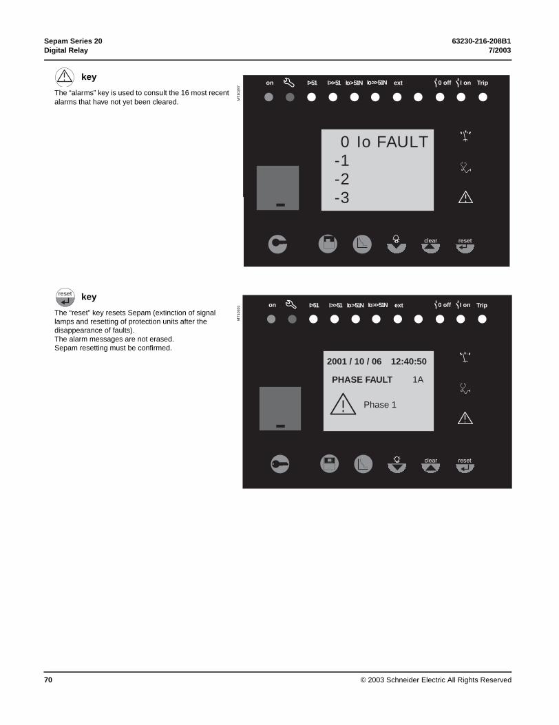
Sepam Series 20 63230-216-208B1Digital Relay 7/2003
© 2003 Schneider Electric All Rights Reserved70
key
MT
1028
7
The “alarms” key is used to consult the 16 most recent alarms that have not yet been cleared.
reset
I onon 0 off
clear
0 Io FAULT-1-2-3
TripextI >> 51I>51 Io >> 51NIo > 51N
key
MT
1030
1
The “reset” key resets Sepam (extinction of signal lamps and resetting of protection units after the disappearance of faults). The alarm messages are not erased.Sepam resetting must be confirmed.
reset
reset
I onon 0 off
clear
2001 / 10 / 06
PHASE FAULT
Phase 1
12:40:50
TripextI >> 51I>51 Io >> 51NIo > 51N
1A

63230-216-208B1 Sepam Series 207/2003 Digital Relay
© 2003 Schneider Electric All Rights Reserved 71
key
MT
1028
4
When an alarm is present on the Sepam display, the "clear" key is used to return to the screen that was present prior to the appearance of the alarm or to a less recent unacknowledged alarm. Sepam is not reset.In the metering or diagnosis or alarm menus, the "clear" key may be used to reset the average currents, peak demand currents, running hours counter and alarm stack when they are shown on the display.
key
MT
1028
3
Press the "lamp test" key for 5 seconds to start up a LED and display test sequence.When an alarm is present, the "lamp test" key is disabled.
clear
reset
I onon 0 off
clear
I1max = 180AI2max = 181AI2max = 180A
TripextI >> 51I>51 Io >> 51NIo > 51N
resetclear
I1 = 162AI2 = 161AI3 = 163A
I onextIo >> 51NIo > 51NI> > 51I>51on 0 off Trip

Sepam Series 20 63230-216-208B1Digital Relay 7/2003
© 2003 Schneider Electric All Rights Reserved72
Blue keys for parameter and protection setting
key
MT
1081
0
The “status” key is used to display and enter the Sepam general settings. They define the protected equipment characteristics and the different optional modules.
key
MT
1081
1
The “protection” key is used to display, set and enable or disable the protection units.
reset
I onon 0 off
clear
General settingslanguage frequencyEnglish 50 HzFrench 60 Hz
TripextI >> 51I>51 Io >> 51NIo > 51N
A/B choice (A actif)= A
reset
I onon 0 off
clear
50/51
TripCurveThreshold
OffOn
Delay
===
1 A
TripextI >> 51I>51 Io >> 51NIo > 51N
inverse110 A100 ms

63230-216-208B1 Sepam Series 207/2003 Digital Relay
© 2003 Schneider Electric All Rights Reserved 73
key
MT
1080
8
The access key is used to enter the passwords for access to the different modes:b protection settingb parameter setting.and return to "operating" mode (with no passwords).
Note: for parameter setting of alarm LEDs and output relays, it is necessary to use the SFT2841 software, "program logic" menu.
reset
I onon 0 off
clear
passwords
apply cancel
TripextI >> 51I>51 Io >> 51NIo > 51N
key
MT
1081
2
The key is used to confirm the protection settings, parameter settings and passwords.
reset
reset
I onon 0 off
clear
50/51
TripCurveThreshold
OffOn
Delay
===
SIT550 A600 ms
1 A
TripextI >> 51I>51 Io >> 51NIo > 51N

Sepam Series 20 63230-216-208B1Digital Relay 7/2003
© 2003 Schneider Electric All Rights Reserved74
key
MT
1081
3
When there are no alarms on the Sepam display and the user is in the status, protection or alarm menu, the
key is used to move the cursor upward.
key
MT
1081
4
When there are no alarms on the Sepam display and the user is in the status, protection or alarm menu, the
key is used to move the cursor downward.
clear
reset
I onon 0 off
clear
50/51
TripCurveThreshold
OffOn
Delay
===
SIT550 A600 ms
1 A
TripextI >> 51I>51 Io >> 51NIo > 51N
reset
I onon 0 off
clear
Timer holdCurveDelay
Delay
==
=
Definite0.00 ms
600 ms
TripextI >> 51I>51 Io >> 51NIo > 51N
apply cancel
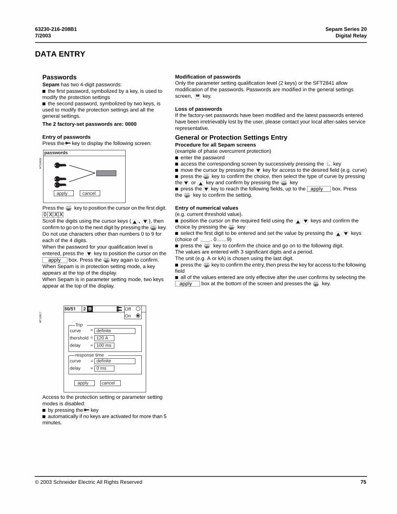
63230-216-208B1 Sepam Series 207/2003 Digital Relay
© 2003 Schneider Electric All Rights Reserved 75
DATA ENTRY
Passwords Modification of passwordsOnly the parameter setting qualification level (2 keys) or the SFT2841 allow modification of the passwords. Passwords are modified in the general settings screen, key.
Sepam has two 4-digit passwords:b the first password, symbolized by a key, is used to modify the protection settingsb the second password, symbolized by two keys, is used to modify the protection settings and all the general settings.
The 2 factory-set passwords are: 0000
Loss of passwordsIf the factory-set passwords have been modified and the latest passwords entered have been irretrievably lost by the user, please contact your local after-sales service representative.
Entry of passwordsPress the key to display the following screen:
General or Protection Settings EntryProcedure for all Sepam screens(example of phase overcurrent protection)b enter the passwordb access the corresponding screen by successively pressing the keyb move the cursor by pressing the key for access to the desired field (e.g. curve)b press the key to confirm the choice, then select the type of curve by pressing the or key and confirm by pressing the keyb press the key to reach the following fields, up to the box. Press the key to confirm the setting.
MT
1081
6
Press the key to position the cursor on the first digit.
Scroll the digits using the cursor keys ( , ), then confirm to go on to the next digit by pressing the key. Do not use characters other than numbers 0 to 9 for each of the 4 digits. When the password for your qualification level is entered, press the key to position the cursor on the
box. Press the key again to confirm. When Sepam is in protection setting mode, a key appears at the top of the display.When Sepam is in parameter setting mode, two keys appear at the top of the display.
Entry of numerical values(e.g. current threshold value).b position the cursor on the required field using the keys and confirm the choice by pressing the keyb select the first digit to be entered and set the value by pressing the keys (choice of . 0……9)b press the key to confirm the choice and go on to the following digit. The values are entered with 3 significant digits and a period. The unit (e.g. A or kA) is chosen using the last digit.b press the key to confirm the entry, then press the key for access to the following fieldb all of the values entered are only effective after the user confirms by selecting the
box at the bottom of the screen and presses the key.
MT
1081
7
Access to the protection setting or parameter setting modes is disabled:b by pressing the keyb automatically if no keys are activated for more than 5 minutes.
reset
reset
applyresetapply cancel
passwords
reset
0 X X X
reset
apply reset
reset
reset
reset
apply reset
apply cancel
Off
On
Tripcurve
thershold
=
delay =
response timecurve
delay =
definite
120 A
100 ms
definite
0 ms
=
=

Sepam Series 20 63230-216-208B1Digital Relay 7/2003
© 2003 Schneider Electric All Rights Reserved76
DEFAULT PARAMETERS, ALL APPLICATIONS
The Sepam units are delivered with default parameter setting and protection setting according to the type of application. These "factory" settings are also used with the SFT2841 software:b for the creation of new files in not connected modeb for a return to the "factory" settings in connected mode.
S20, T20 and M20 applicationsHardware configurationb identification: Sepam xxxxb model: UXb MES module: absentb MET module: absentb MSA module: absentb DSM module: presentb ACE module: absent.
Output parameter settingb outputs used: O1 to O4b shunt trip units: O1, O3b undervoltage trip units: O2, O4b impulse mode: no (latched).
Program logicb circuit breaker control: nob logic discrimination: nob logic input assignment: not used.
General characteristicsb network frequency: 50 Hzb group of settings: Ab enable remote setting: nob working language: Englishb CT rating: 5 Ab number of CTs: 3 (l1, l2, l3)b rated current In: 630 Ab basic current Ib: 630 Ab integration period: 5 mnb residual current: 3I sumb pre-trig for disturbance recording: 36 periods.
Protection functionsb all the protections are "off"b the settings comprise values and choices that are informative and consistent with the general characteristics by default (in particular rated current In)b tripping behavior:v latching: yesv activation of output O1: yesb disturbance recording triggering: with.
Control matrixEach Sepam 1000+ has program logic by default according to the type (S20, T20,…) as well as messages for the different signal lamps. The functions are assigned according to the most frequent use of the unit. This parameter setting may be customized if required using the SFT2841 software package.b S20 application:v activation of output O2 upon protection trippingv activation of indicators according to front panel markingsv watchdog on output O4v disturbance recording triggering upon signal pick-up.b complements for T20 application:v activation of O1 without latching upon tripping of temperature monitoring 1 to 7v activation of O1 and indicator L9 without latching upon thermal overload tripping.b complements for M20 application:v activation of outputs O1 and O2 and indicator L9 upon tripping of functions 37 phase undercurrent) and 51 LR (locked rotor)v activation of output O2 upon tripping of function 66 (starts per hour)b latching for function 51 LR.

63230-216-208B1 Sepam Series 207/2003 Digital Relay
© 2003 Schneider Electric All Rights Reserved 77
B21(1) and B22 applications Protection functionsb all the protection functions are “off”b the settings comprise values and choices that are informative and consistent with the general characteristics by defaultb latching: nob disturbance recording triggering: with.
Control matrixb assignment of output relays and indicators according to chart:
Hardware configurationb identification: Sepam xxxxb model: UXb MES module: absentb MET module: absentb MSA module: absentb DMS module: presentb ACE module: absent.
Output parameter settingb outputs used: O1 to O4 b shunt coils: O1 to O3b undervoltage coils: O4b impulse mode: no (latched).
Program logicb circuit breaker control: no b assignment of logic inputs: not used.
General characteristicsb network frequency: 50 Hz b enable remote setting: nob working language: Englishb primary rated voltage (Unp): 20 kVb secondary rated voltage (Uns): 100 Vb voltages measured by VTs: V1, V2, V3b residual voltage: sum of 3Vsb pre-trig for disturbance recording: 36 periods.
Functions Outputs Indicators
B21 B22 O1 O2 O3 O4 L1 L2 L3 L4 L5 L6 L7 L8 L9
27D-1 27D-1 b b
27D-2 27D-2 b b b
27R 27R b b
27-1 27-1 b b
27-2 27-2 b b b
27S-1 27S-1 b b b
27S-2 27S-2 b b b
27S-3 27S-3 b b b
59-1 59-1 b b
59-2 59-2 b b b
59N-1 59N-1 b b
59N-2 59N-2 b b b
81H 81H b b b
81L-1 81L-1 b b
81L-2 81L-2 b b b
81R b b b
b disturbance recording triggering upon signal pick-upb watchdog on output O4.
Indicator markingL1 : U < 27L2 : U < 27DL3 : U < 27RL4 : U > 59L5 : U > 59NL6 : F > 81HL7 : F < 81LL8 : F << 81LL9 : Trip
(1) Type B21 performs the same functions as cancelled type B20.

Sepam Series 20 63230-216-208B1Digital Relay 7/2003
© 2003 Schneider Electric All Rights Reserved78
COMMISSIONING
Principles and Methods
Protection relay testingProtection relays are tested prior to commissioning, with the dual aim of maximizing availability and minimizing the risk of malfunctioning of the assembly being commissioned. The problem consists of defining the consistency of the appropriate tests, keeping in mind that the relay is always involved as the main link in the protection chain.Therefore, protection relays based on electromechanical and static technologies, must be systematically submitted to detailed testing, not only to qualify relay commissioning, but also to check that they actually are in good operating order and maintain the required level of performance.
The Sepam concept makes it possible to do away with such testing, since:b the use of digital technology guarantees the reproducibility of the performances announcedb each of the Sepam functions has undergone full factory-qualificationb an internal self-testing system provides continuous information on the state of the electronic components and the integrity of the functions (e.g. automatic tests diagnose the level of component polarization voltages, the continuity of the analog value acquisition chain, non-alteration of RAM memory, absence of settings outside the tolerance range) and thereby guarantees a high level of availability
Sepam is therefore ready to operate without requiring any additional qualification testing that concerns it directly.
Sepam commissioning testsThe preliminary Sepam commissining tests may be limited to a commissioning check, i.e.:b checking of compliance with BOMs and hardware installation diagrams and rules during a preliminary general checkb checking of the compliance of the general settings and protection settings entered with the setting sheetsb checking of current or voltage input connection by secondary injection testsb checking of logic input and output connection by simulation of input data and forcing of output statusb validation of the complete protection chain (possible customized logical functions included)b checking of the connection of the optional MET148-2 and MSA141 modules.The various checks are described further on.
General principles
b all the tests should be carried out with the MV cubicle completely isolated and the MV circuit breaker racked out (disconnected and open)b all the tests are to be performed in the operating situation: no wiring or setting changes, even temporary changes to facilitate testing, are allowed.b the SFT2841 parameter setting and operating software is the basic tool for all Sepam users. It is especially useful during Sepam commissioning tests. The tests described in this document are systematically based on the use of that tool. The commissioning tests may be performed without the SFT2841 software for Sepam units with advanced UMIs.
Method
For each Sepam:b only carry out the checks suited to the hardware configuration and the functions activated(A comprehensive description of all the tests is given further on)b use the test sheet provided to record the results of the commissioning tests.
Checking of current or voltage input connectionsThe secondary injection tests to be carried out to check the connection of the current and voltage inputs are described according to:b the type of current or voltage sensors connected to Sepam, in particular for residual current or voltage measurementb the type of injection generator used for the tests: single-phase generator.
The different possible tests are described further on by:b a detailed test procedureb the connection diagram of the associated test generator.
The table below specifies the tests to be carried out according to the type of measurement sensors and type of generator used, and indicates the page on which each test is described.
Current sensors 3 CTs 1 core balance CT
Voltage sensors 3 VTs 1 residual VTSingle-phase generator
See page 82. See page 83. See page 84. See page 85.

63230-216-208B1 Sepam Series 207/2003 Digital Relay
© 2003 Schneider Electric All Rights Reserved 79
Testing and metering equipment required
DANGERHAZARD OF ELECTRIC SHOCK, BURN, OR EXPLOSION
• This equipment must be installed and serviced only by qualified personnel.
• Qualified persons performing diagnostics or troubleshooting that require electrical conductors to be energized must comply with NFPA 70 E - Standard for Electrical Safety Requirements for Employee Workplaces and OSHA Standards - 29 CFR Part 1910 Subpart S - Electrical.
• Carefully inspect the work area for tools and objects that may have been left inside the equipment.
• Use caution while removing or installing panels so that they do not extend into the energized bus; avoid handling the panels, which could cause personal injury.
Failure to follow these instructions will result in death or serious injury.
Generators
b dual sinusoidal AC current and voltage generator:v 50 or 60 Hz frequency (according to the country)v current adjustable 0–50A rmsv adjustable voltage 0–150Vv single-phase typeb DC voltage generator:v adjustable from 48 to 250 V DC, for adaptation to the voltage level of the logic input being tested.
Accessories
b plug with cord to match the "current" test terminal box installedb plug with cord to match the "voltage" test terminal box installedb electric cord with clamps, wire grip or touch probes.
Metering devices (built into the generator or separate)
b 1 ammeter, 0 to 50 A rmsb 1 voltmeter, 0 to 150 V rms
Computer equipment
b PC with minimal configuration: v MicroSoft Windows 95 / 98 / NT 4.0 / XP / 2000v 133 MHz Pentium processor,v 64 MB of RAM (or 32 MB with Windows 95 / 98v 64 MB free on hard diskv CD-ROM driveb SFT2841 softwareb CCA783 serial connection cord between the PC and Sepam.
Sepam Series 20 63230-216-208B1Digital Relay 7/2003
© 2003 Schneider Electric All Rights Reserved80
Documents
b complete connection diagram of Sepam and additional modules, with: v phase current input connection to the corresponding CTs via the test terminal boxv residual current input connectionv phase voltage input connection to the corresponding VTs via the test terminal boxv residual voltage input connection to the corresponding VTs via the test terminal boxv logic input and output connectionv temperature sensor connectionv analog output connectionb hardware BOMs and installation rulesb group of Sepam parameter and protection settings, available in paper format.
Pre-test Equipment CheckChecking to be done prior to energizing
Apart from the mechanical state of the equipment, use the diagrams and BOMs provided by the contractor to check:b identification of Sepam and accessories determined by the contractorb correct grounding of Sepam (via terminal 17 of the 20-pin connector)b correct connection of auxiliary voltage (terminal 1: AC or positive polarity; terminal 2: AC or negative polarity)b presence of a residual current measurement core balance CT and/or additional modules connected to Sepam, when applicableb presence of test terminal boxes upstream from the current inputs and voltage inputsb conformity of connections between Sepam terminals and the test terminal boxes.
Connections
Check that the connections are tightened (with equipment non-energized).The Sepam connectors must be correctly plugged in and locked.
Energizing
Switch on the auxiliary power supply. Check that Sepam performs the following initialization sequence, which lasts approximately 6 seconds :b green ON and red indicators onb red indicator offb pick-up of "watchdog" contact.The first screen displayed is the phase current measurement screen.
Implementation of the SFT2841 software for PC
b start up the PCb connect the PC RS232 serial port to the communication port on the front panel of Sepam using the CCA783 cableb start up the SFT2841 software, by clicking on the related iconb choose to connect to the Sepam to be checked.
Identification of Sepam
b note the Sepam serial number given on the label stuck to the right side plate of the base unitb note the Sepam type and software version using the SFT2841 software,"Sepam Diagnosis" screenb enter them in the test sheet. See page 88.

63230-216-208B1 Sepam Series 207/2003 Digital Relay
© 2003 Schneider Electric All Rights Reserved 81
Pre-test Settings Check
Determination of parameter and protection settings
All of the Sepam parameter and protection settings are determined ahead of time by the design department in charge of the application, and should be approved by the customer.It is presumed that the study has been carried out with all the attention necessary, or even consolidated by a network coordination study. All of the Sepam parameter and protection settings should be available at the time of commissioning:b in paper file format (with the SFT2841 software, the parameter and protection setting file for a Sepam may be printed directly or exported in a text file for editing) b and, when applicable, in the format of a file to be downloaded into Sepam using the SFT2841 software.
Checking of parameters and protection settings
Verify that settings are study values instead of default settings.The aim of this check is not to confirm the relevance of the parameter and protection settings.b go through all the parameter and protection setting screens in the SFT2841 software, in the order proposed in guided modeb for each screen, compare the values entered in the Sepam with the values recorded in the parameter and protection setting fileb correct any parameter and protection settings that have not been entered correctly, proceeding as indicated in the "Expert UMI" section of the Use chapter of this manual.
Conclusion
Once the checking has been done and proven to be conclusive, as of that phase, the parameter and protection settings should not be changed any further and are considered to be final.In order to be conclusive, the tests which follow must be performed with these parameter and protection settings; no temporary modification of any of the values entered, with the aim of facilitating a test, is permissible.

Sepam Series 20 63230-216-208B1Digital Relay 7/2003
© 2003 Schneider Electric All Rights Reserved82
Checking of phase current input connection
Description: Check to be carried out for Sepam 1000+ S20, T20 or M20.
Procedure:b to inject a current into the phase 1 input, connect the single-phase generator to the test terminal box using the plug provided, in accordance with the diagram below:
MT
1088
7
b turn on the generatorb inject the CT rated secondary current, i.e. 1 A or 5 Ab use the SFT2841 software to check that the phase 1 current value is approximately equal to the CT rated primary currentb if the residual current is calculated by taking the sum of the 3 phase currents, use the SFT2841 software to check that the residual current value is approximately equal to the CT rated primary currentb if the residual current is measured via 3 phase CTs connected to a CSH30 interposing ring CT, use the SFT2841 software to check that the residual current value is approximately equal to the CT rated primary currentb turn off the generatorb proceed in the same way for the other 2 phase current inputsb at the end of the test, put the cover back on the test terminal box.
L1
L2
L3
14
52
63
18
A
B
19
test terminal box
A
IN
A
eg.: I1
Sepam 1000+ S20/T20/M20
single-phase currentinjection box

63230-216-208B1 Sepam Series 207/2003 Digital Relay
© 2003 Schneider Electric All Rights Reserved 83
Checking of residual current input connection
Description: Check to be carried out for Sepam 1000+ S20, T20 or M20, when the residual current is measured by a specific sensor:b CSH120 or CSH200 core balance CTb another core balance CT connected to an ACE990 interfaceb a single 1 A or 5 A CT encompassing the 3 phases, connected to a CSH30 interposing ring CT.
Procedure: b connect the single-phase current generator to inject current into the primary circuit of the core balance CT or the CT, in accordance with the diagram below:
MT
1088
8
b turn on the generatorb inject a 5 A primary residual currentb use the SFT2841 software to check that the residual current value is approximately equal to 5 Ab turn the generator off.
L1
L2
L3
14
52
63
18
A
B
19
A
IN
Sepam 1000+ S20/T20/M20
A
test terminal box
single-phase currentinjection box
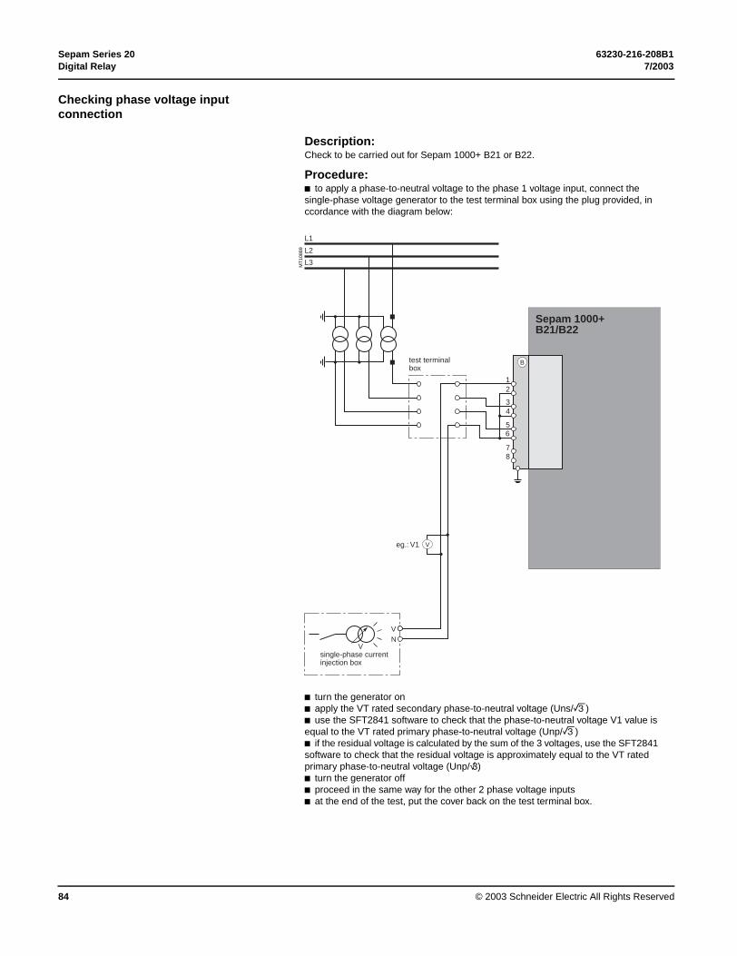
Sepam Series 20 63230-216-208B1Digital Relay 7/2003
© 2003 Schneider Electric All Rights Reserved84
Checking phase voltage input connection
Description: Check to be carried out for Sepam 1000+ B21 or B22.
Procedure:b to apply a phase-to-neutral voltage to the phase 1 voltage input, connect the single-phase voltage generator to the test terminal box using the plug provided, in ccordance with the diagram below:
MT
1088
9
b turn the generator onb apply the VT rated secondary phase-to-neutral voltage (Uns/3)b use the SFT2841 software to check that the phase-to-neutral voltage V1 value is equal to the VT rated primary phase-to-neutral voltage (Unp/3)b if the residual voltage is calculated by the sum of the 3 voltages, use the SFT2841 software to check that the residual voltage is approximately equal to the VT rated primary phase-to-neutral voltage (Unp/√3)b turn the generator offb proceed in the same way for the other 2 phase voltage inputsb at the end of the test, put the cover back on the test terminal box.
L1
L2
L3
21
34
56
B
V
VN
eg.: V1
Sepam 1000+ B21/B22
V
78
test terminal box
single-phase currentinjection box

63230-216-208B1 Sepam Series 207/2003 Digital Relay
© 2003 Schneider Electric All Rights Reserved 85
Checking of residual voltage input connection
Description: Check to be carried out for Sepam 1000+ B21 or B22, when the residual voltage is measured by 3 VTs on the secondary circuits connected in an open delta arrangement.
Procedure:b connect the single-phase voltage generator to the terminal test box using the plug provided, in accordance with the diagram below:
MT
1089
0
b turn on the generatorb apply the VT rated secondary phase-to-neutral voltage (Uns/3)b use the SFT2841 software to check the residual voltag value Vob Vo should be equal to the VT rated primary phase-to-neutral voltage (Unp/3 or Vnp) if the VTs deliver Uns/3 to the secondary circuitb Vo should be equal to the VT rated primary phase-to-phase voltage (Unp or 3Vnp) if the VTs deliver Uns/3 to the secondary circuitb turn the generator offb put the cover back on the terminal test box.
L1
L2
L3
21
34
56
B
test terminalbox
V
VN
eg.: V1
Sepam 1000+ B21/B22
V
78
single-phase currentinjection box

Sepam Series 20 63230-216-208B1Digital Relay 7/2003
© 2003 Schneider Electric All Rights Reserved86
Logic Input and Output
MT
1119
4
Checking of logic input connection
Proceed as follows for each input:b if the input supply voltage is present, use an electric cable to short-circuit the contact that delivers logic data to the input at 19.2–275 V dcb if the input supply voltage is not present, apply a voltage supplied by the DC voltage generator to the terminal of the contact linked to the chosen input, being sure to comply with the suitable polarity and levelb observe the change of status of the input using the SFT2841 software, in the "Input, output, indicator status" screenb at the end of the test, if necessary, press the SFT2841 Reset key to clear all messages and deactivate all outputs.
"Input, output, indicator status’’ screen.
MT
1119
5
Checking of logic output connection
Check carried out using the "Output relay test" function, activated via the SFT2841 software, in the "Sepam Diagnosis" screen. Only output O4, when used for the watchdog, can be tested.This function requires prior entry of the "Parameter setting" password.b activate each output relay using the buttons in the SFT2841 softwareb the activated output relay changes status over a period of 5 secondsb observe the change of status of the output relay through the operation of the related switchgear (if it is ready to operate and is powered), or connect a voltmeter to the terminals of the output contact (the voltage cancels itself out when the contact closes)b at the end of the test, press the SFT2841 Reset key to clear all messages and deactivate all outputs.
‘’Sepam diagnosis and output relay test’’ screen.

63230-216-208B1 Sepam Series 207/2003 Digital Relay
© 2003 Schneider Electric All Rights Reserved 87
Validation of Protection Output and Custom Logic Functions
Optional Module Connection
PrincipleThe complete protection chain is validated during the simulation of a fault that causes tripping of the breaking device by Sepam.
Procedureb select one of the protection functions that triggers tripping of the breaking deviceb according to the selected function or functions, inject a current and/or apply a voltage that corresponds to a faultb observe the tripping of the breaking device
At the end of all the voltage or current application type checks, put the covers back on the test terminal boxes.
Checking of RTD inputs to the MET148-2 module
The temperature monitoring function provided by Sepam T40, T42, M41 and G40 units checks the connection of each RTD that is configured.An "RTD FAULT" alarm is generated whenever one of the RTDs is detected as being short-circuted or disconnected (absent).To identify the faulty RTD or RTDs:b display the temperature values measured by Sepam using the SFT2841 softwareb check the consistency of the temperatures measured:v the temperature displayed is "****" if the RTD is short-circuited (T < -35°C)v the temperature displayed is "-****" if the RTD is disconnected (T > 205°C).
Checking of analog output connection to the MSA141 module
b identify the measurement associated by parameter setting to the analog output using the SFT2841 softwareb simulate, if necessary, the measurement linked to the analog output by injectionb check the consistency between the value measured by Sepam and the indication given by the device connected to the analog output.

Sepam Series 20 63230-216-208B1Digital Relay 7/2003
© 2003 Schneider Electric All Rights Reserved88
Test sheet Sepam series 40 Project: Type of Sepam 1000+
Switchboard: Serial number
Cubicle: Software version V
Overall checksCheck of the box v when the check has been made and been conclusiveType of check
Preliminary general examination, prior to energizing vEnergizing vParameter and protection settings vLogic input connection vLogic output connection vValidation of the complete protection chain vAnalog output connection to the MSA141 module vTemperature sensor input connection to the MET148 module (for type T20 or M20) vChecking of Sepam 1000+ S20, T20 or M20 current inputsType of check Test performed Result Display
Phase current input connection
Secondary injection of CT rated current, i.e. 1 A or 5 A
CT rated primary currentI1 = v
I2 =
I3 =Residual current value obtained by 3 phase CTs
Secondary injection of CT rated current, i.e. 1 A or 5 A
CT rated primary currentIo = v
Residual current input connection to a specific sensor:b CSH120 or CSH200b other core balance CT + ACE990b 1 x 1 A or 5 A CT + CSH30
Injection of 5 A into primary circuit of core balance CT or CT
Injected current valueIo = v
Checking of Sepam 1000+ B21 or B22 voltage inputsType of check Test performed Result Display
Phase voltage input connection
Secondary injection of VT rated phase-to-neutral voltage Uns/3
VT rated primary phase-to-neutral voltage Unp/3 V1 = v
V2 =
V3 =Residual voltage value obtained by 3 phase VTs
Secondary injection of VT rated phase-to-neutral voltage Uns/3
VT rated primary phase-to-neutral voltage Unp/3 Vo = v
Connection of residual voltage input
Secondary injection of voltage Uns/3
Residual voltage= Unp/3 (if Uns/3 VT)= Unp (if Uns/3 VT)
Vo = v
Tests performed on:
By:
Signatures
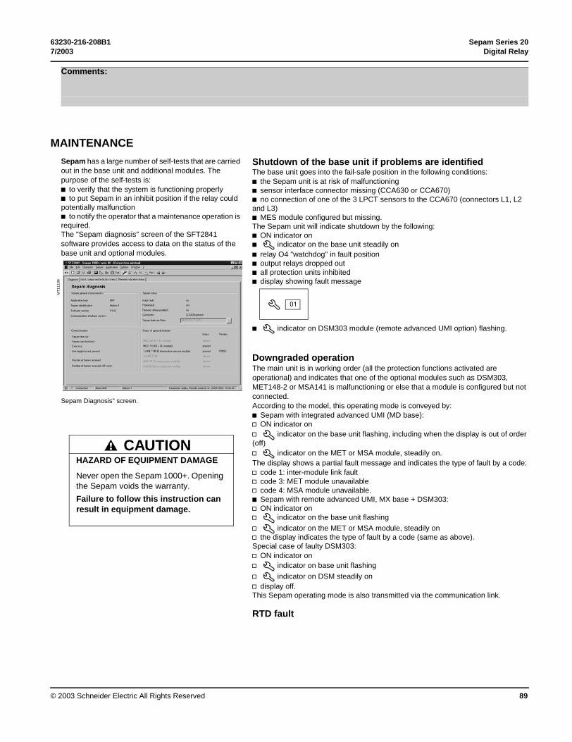
63230-216-208B1 Sepam Series 207/2003 Digital Relay
© 2003 Schneider Electric All Rights Reserved 89
MAINTENANCE
Comments:
Sepam has a large number of self-tests that are carried out in the base unit and additional modules. The purpose of the self-tests is:b to verify that the system is functioning properlyb to put Sepam in an inhibit position if the relay could potentially malfunctionb to notify the operator that a maintenance operation is required.The "Sepam diagnosis" screen of the SFT2841 software provides access to data on the status of the base unit and optional modules.
Sepam Diagnosis" screen.
Shutdown of the base unit if problems are identified
MT
1119
6
The base unit goes into the fail-safe position in the following conditions:b the Sepam unit is at risk of malfunctioningb sensor interface connector missing (CCA630 or CCA670)b no connection of one of the 3 LPCT sensors to the CCA670 (connectors L1, L2 and L3) b MES module configured but missing.The Sepam unit will indicate shutdown by the following:b ON indicator onb indicator on the base unit steadily onb relay O4 "watchdog" in fault positionb output relays dropped outb all protection units inhibitedb display showing fault message
b indicator on DSM303 module (remote advanced UMI option) flashing.
Downgraded operationThe main unit is in working order (all the protection functions activated are operational) and indicates that one of the optional modules such as DSM303, MET148-2 or MSA141 is malfunctioning or else that a module is configured but not connected. According to the model, this operating mode is conveyed by:b Sepam with integrated advanced UMI (MD base):v ON indicator onv indicator on the base unit flashing, including when the display is out of order (off)v indicator on the MET or MSA module, steadily on.The display shows a partial fault message and indicates the type of fault by a code:v code 1: inter-module link faultv code 3: MET module unavailablev code 4: MSA module unavailable.b Sepam with remote advanced UMI, MX base + DSM303:v ON indicator onv indicator on the base unit flashing
v indicator on the MET or MSA module, steadily onv the display indicates the type of fault by a code (same as above).Special case of faulty DSM303:v ON indicator onv indicator on base unit flashing
v indicator on DSM steadily onv display off.This Sepam operating mode is also transmitted via the communication link.
RTD fault
HAZARD OF EQUIPMENT DAMAGE
Never open the Sepam 1000+. Opening the Sepam voids the warranty.
Failure to follow this instruction can result in equipment damage.
CAUTION
01

Sepam Series 20 63230-216-208B1Digital Relay 7/2003
© 2003 Schneider Electric All Rights Reserved90
Each temperature monitoring function, when activated, detects whether the RTD associated with the MET148-2 module is short-circuited or disconnected.When this is the case, the alarm message "RTD FAULT" is generated.Since this alarm is common to the 8 functions, the identification of the malfunctioning RTD or RTDs is obtained by looking up the measured values:b measurement displayed "****" if the sensor is short-circuited (T < -35°C)b measurement displayed "-****" if the sensor is disconnected (or T > +205°C)
Other faultsSpecific faults indicated by a screen:b DSM303 version incompatible (if version < V0146).
MaintenanceThe Sepam 1000+ does not require regular maintenance or calibration, nor does it contain any user-serviceable parts. If the Sepam 1000+ requires service, contact your local sales representative, or call the POWERLOGIC Technical Support Center for assistance.
Getting Technical SupportIf you have questions about the Sepam 1000+ or other POWERLOGIC and POWERLINK products, contact the Power Management Operation Technical Support Center. The hours are Monday–Friday, 7:30 am–4:30 pm (Central time). Although the fax is available seven days a week, 24 hours a day, if you send your fax outside of these business hours, you will receive your response the next business day. Be sure to include your name and company, address, phone number, types of POWERLOGIC products, and a detailed description of the problem or question. Support numbers are as follows:Phone: (615) 287-3400Fax: (615) 287-3404Email: [email protected] technical publications, visit www.powerlogic.com.


Bulletin No. 63230-216-208B1 July 2003 © 2003 Schneider Electric All Rights Reserved.Replaces 63230-216-208 dated 6/2001
Schneider ElectricPower Management Operation TECHNICAL SUPPORT295 Tech Park Dr, Suite 100LaVergne, TN USA 37086Tel. : (615) 287-3400Fax : (615) 287-3404e-mail: [email protected]