Embed Size (px)
Citation preview
1
Protectionand control
Sepam rangeSepam 1000UseCommissioning
■ Merlin Gerin ■ Square D ■ Telemecanique
2
contents
description / use
front of device 3
access to measurements and parameters 4
parameter setting mode 5
messages 6
rear of device 7
use (current operations)
energizing 8
meter key 8
status key 9
relay key 11
loop arrangement of measurements and parameters 13
reset key 16
lamp test 16
commissioning
checking prior to commissioning 17
commissioning 18
protection 19
protection function setting ranges 20
program logic 21
connection of logic ouputs 20
modification of program logic 22
logic input operation parameter setting 24
maintenance
indicators and display messages 25
unwanted tripping, no tripping 25
tests 25
Sepam replacement 25
Sepam 1000 identification 26
Sepam 1000 documentation 27
9644
3
description / use
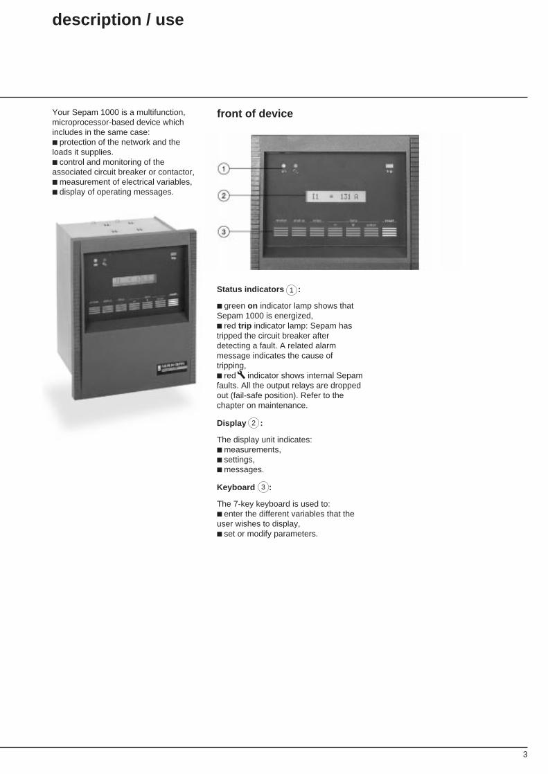
Your Sepam 1000 is a multifunction,microprocessor-based device whichincludes in the same case:■ protection of the network and theloads it supplies.■ control and monitoring of theassociated circuit breaker or contactor,■ measurement of electrical variables,■ display of operating messages.
front of device
Status indicators :
■ green on indicator lamp shows thatSepam 1000 is energized,■ red trip indicator lamp: Sepam hastripped the circuit breaker afterdetecting a fault. A related alarmmessage indicates the cause oftripping,■ red indicator shows internal Sepamfaults. All the output relays are droppedout (fail-safe position). Refer to thechapter on maintenance.
Display :
The display unit indicates:■ measurements,■ settings,■ messages.
Keyboard :
The 7-key keyboard is used to:■ enter the different variables that theuser wishes to display,■ set or modify parameters.
1
2
3
4
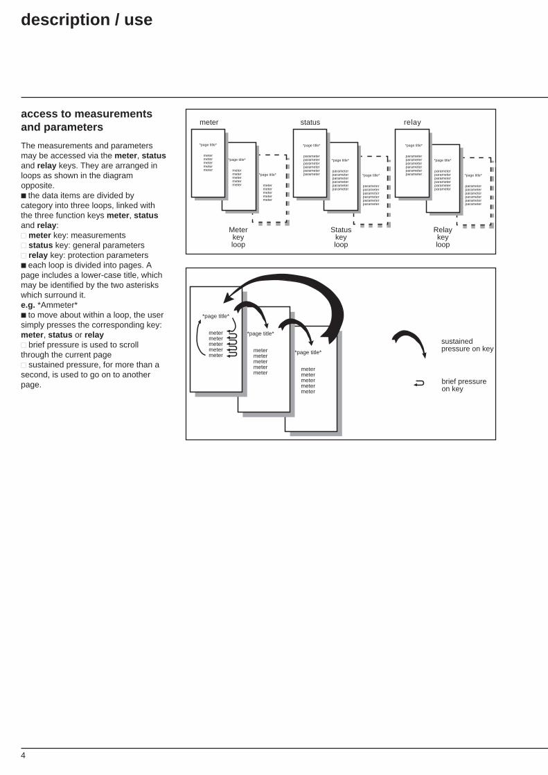
access to measurementsand parameters
The measurements and parametersmay be accessed via the meter , statusand relay keys. They are arranged inloops as shown in the diagramopposite.■ the data items are divided bycategory into three loops, linked withthe three function keys meter , statusand relay :■■ meter key: measurements■■ status key: general parameters■■ relay key: protection parameters■ each loop is divided into pages. Apage includes a lower-case title, whichmay be identified by the two asteriskswhich surround it.e.g. *Ammeter*■ to move about within a loop, the usersimply presses the corresponding key:meter , status or relay■■ brief pressure is used to scrollthrough the current page■■ sustained pressure, for more than asecond, is used to go on to anotherpage.
U>tu>
relaymeter status
*page title*
metermetermetermetermeter
*page title*
metermetermetermetermeter
*page title*
metermetermetermetermeter
*page title*
parameterparameterparameterparameterparameterparameter
*page title*
parameterparameterparameterparameterparameterparameter
Statuskeyloop
Relaykeyloop
*page title*
parameterparameterparameterparameterparameterparameter
*page title*
parameterparameterparameterparameterparameterparameter
*page title*
parameterparameterparameterparameterparameterparameter
*page title*
parameterparameterparameterparameterparameterparameter
Meter keyloop
*page title*
metermetermetermetermeter
*page title*
metermetermetermetermeter
*page title*
metermetermetermetermeter
sustained pressure on key
brief pressureon key
description / use

5
parameter setting mode
This is the mode that is used to setSepam parameters.
■ the parameter setting mode activiatesthe data- , data+ and enter keys thatare used to set the parameters.■ to switch to parameter setting mode,the user presses the P key on theback of Sepam. This key may beaccessed using the tip of a pen.■ to exit parameter setting, the usermay:■■ manually press the P key on theback of Sepam again,■■ exit automatically if no keys havebeen pressed for 2 minutes.■ the parameter setting mode may beidentified on the display unit by a P asthe first character on the right.
I1 = 0.0 A P
Parameter setting
■ switch to parameter setting mode bypressing the P key on the rear ofSepam for one second,■ select the parameter to be set usingthe appropriate key (status or relay ),■ use the data- and data+ keys toscroll the possible settings until therequired value is reached,■ press the enter key to store the newparameter value.Parameter setting is complete.Any parameter values that have notbeen stored will blink on the display.Ensure that the parameter is displayedsteadily after the enter key is pressed.Whenever Sepam detects a settingproblem, a CHECK SETTINGSmessage appears on the display. Referto the section entitled CHECKSETTINGS (p. 16).
example of display:
I1 = 0.0 A P
In = 100 A P
In = "150 A" P
In = 150 A P
1
1
CHECK SETTINGS
6
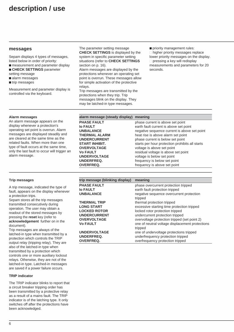
The parameter setting messageCHECK SETTINGS is displayed by thesystem in specific parameter settingsituations (refer to CHECK SETTINGSsection on p. 16).Alarm messages are displayed by theprotections whenever an operating setpoint is overrun. These messages allowfor simple activation of the protectiverelays.Trip messages are transmitted by theprotections when they trip. Tripmessages blink on the display. Theymay be latched-in type messages.
messages
Sepam displays 4 types of messages,listed below in order of priority:■ measurement and parameter display■ CHECK SETTINGS parametersetting message■ alarm messages■ trip messages
Measurement and parameter display iscontrolled via the keyboard.
■ priority management rules:■■ higher priority messages replacelower priority messages on the display.■■ pressing a key will redisplaymeasurements and parameters for 20seconds.
Alarm messagesAn alarm message appears on thedisplay whenever a protection'soperating set point is overrun. Alarmmessages are displayed steadily andare cleared at the same time as therelated faults. When more than onetype of fault occurs at the same time,only the last fault to occur will trigger analarm message.
alarm message (steady display) meaning
PHASE FAULT phase current is above set pointIo FAULT earth fault current is above set pointUNBALANCE negative sequence current is above set pointTHERMAL ALARM heat rise is above alarm set pointUNDERCURRENT phase current is below set pointSTART INHIBIT. starts per hour protection prohibits all startsOVERVOLTAGE voltage is above set pointVo FAULT residual voltage is above set pointUNDERVOLTAGE voltage is below set pointUNDERFREQ. frequency is below set pointOVERFREQ. frequency is above set point
Trip messages
A trip message, indicated the type offault, appears on the display whenevera protection trips.Sepam stores all the trip messagestransmitted consecutively duringoperation. The user may obtain areadout of the stored messages bypressing the reset key (refer toacknowledgement further on in thedocument).Trip messages are always of thelatched-in type when transmitted by aprotection which controls the TRIPoutput relay (tripping relay). They arealso of the latched-in type whentransmitted by a protection whichcontrols one or more auxiliary lockoutrelays. Otherwise, they are not of thelatched-in type. Latched-in messagesare saved if a power failure occurs.
TRIP indicator
The TRIP indicator blinks to report thata circuit breaker tripping order hasbeen transmitted by a protective relayas a result of a mains fault. The TRIPindicator is of the latching type. It onlyswitches off after the protections havebeen acknowledged.
trip message (blinking display) meaning
PHASE FAULT phase overcurrent protection trippedIo FAULT earth fault protection trippedUNBALANCE negative sequence overcurrent protection
trippedTHERMAL TRIP thermal protection trippedLONG START excessive starting time protection trippedLOCKED ROTOR locked rotor protection trippedUNDERCURRENT undercurrent protection trippedOVERVOLTAGE overvoltage protection tripped (set point 2)Vo FAULT one of neutral voltage displacement protections
trippedUNDERVOLTAGE one of undervoltage protections trippedUNDERFREQ. underfrequency protection trippedOVERFREQ. overfrequency protection tripped
description / use
7
2 1
1 2 345678
+-
1 2 3456
SW2
SW1
A
A1 2 345678
1 2 34
A
SW 1
AS'EM ES1
0B
B
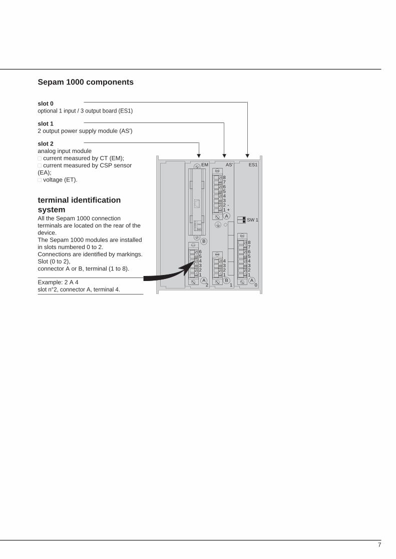
Sepam 1000 components
slot 0optional 1 input / 3 output board (ES1)
slot 12 output power supply module (AS')
slot 2analog input module■■ current measured by CT (EM);■■ current measured by CSP sensor(EA);■■ voltage (ET).
terminal identificationsystemAll the Sepam 1000 connectionterminals are located on the rear of thedevice.The Sepam 1000 modules are installedin slots numbered 0 to 2.Connections are identified by markings.Slot (0 to 2),connector A or B, terminal (1 to 8).
Example: 2 A 4slot n°2, connector A, terminal 4.
8
use (current operations)
energizing
When re-energized after a break in theauxiliary power supply, Sepam 1000automatically restarts according to thefollowing sequence which lasts about 4seconds:■ green on and red indicators lightup,■ extinction of red indicator,■ resetting of watchdog contact,
■ display of the first message (versionname followed by version number).Sepam is then in operation.Sepam 1000 performs the functions ofa precision measurement and alarmprocessing unit.The values are displayed directly withthe related unit A, kA, etc. Themessages are clearly worded.
The device is operated via the front, byusing the 7 keys on the keyboard:■ meter : access to measurements■ status : access to general parameters■ relay : access to protection parameters■ data- , data+ and enter : setting keys(activated in P mode only)■ reset : acknowledgement, trip messagereadout, resetting to zero.
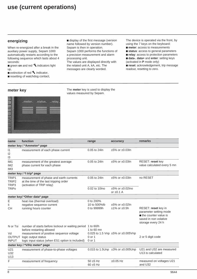
meter key The meter key is used to display thevalues measured by Sepam.
TRIP3 (activation of TRIP relay)TRIPo
name function range accuracy remarks
meter key / *Ammeter* page
I1 measurement of each phase current 0.05 to 24In ±5% or ±0.03InI2I3
IM1 measurement of the greatest average 0.05 to 24In ±5% or ±0.03In RESET: reset keyIM2 phase current for each phase value calculated every 5 mnIM3
meter key / *I trip* page
TRIP1 measurement of phase and earth currents 0.05 to 24In ±5% or ±0.03In no RESETTRIP2 at the time of the last tripping order
0.02 to 10Ino ±5% or ±0.02Inoor ±0.1 A
meter key/ *Other data* page
E heat rise (thermal overload) 0 to 200%Ii negative sequence current 10 to 500%Ib ±5% or ±0.02InCH running hours counter 0 to 99999h ±1% or ±0.5h RESET: reset key in
parameter setting mode■ the counter value issaved in non volativestorage every 24 h
N or Tsi number of starts before lockout or waiting period 1 to 60/hbefore restarting allowed 1 to 60 mn
Vd measurement of positive sequence voltage 0.025 to 1.5 Vnp ±5% or ±0.005VnpOUTPUT logic output status 0 or 1 2 or 5 digit codeINPUT logic input status (when ES1 option is included) 0 or 1
meter key / *V/Hz meter* page
U21 measurement of phase-to-phase voltages 0.015 to 1.5Unp ±3% or ±0.005Unp U21 and U32 are measuredU32 U13 is calculatedU13
F measurement of frequency 50 ±5 Hz ±0.05 Hz measured on voltages U2160 ±5 Hz and U32
9644
9
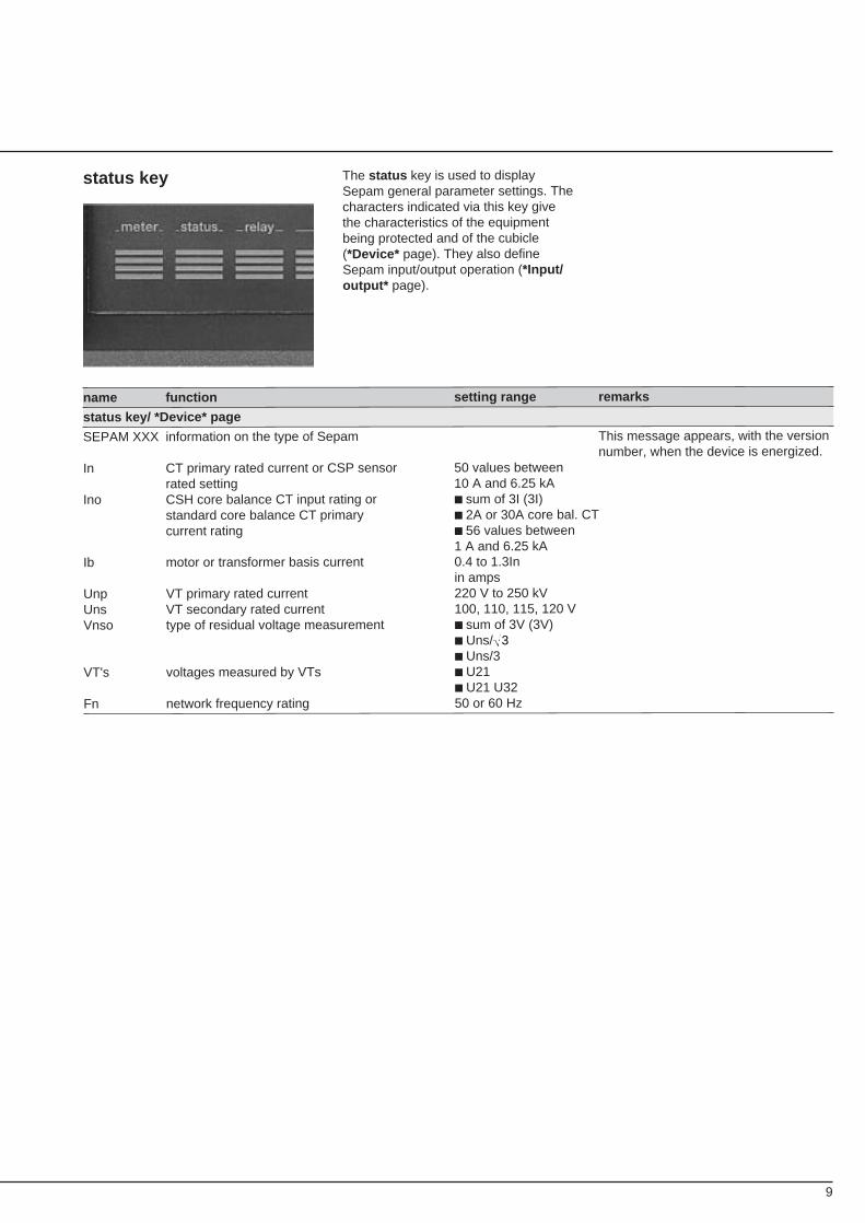
status key The status key is used to displaySepam general parameter settings. Thecharacters indicated via this key givethe characteristics of the equipmentbeing protected and of the cubicle(*Device* page). They also defineSepam input/output operation (*Input/output* page).
name function setting range remarks
status key/ *Device* page
SEPAM XXX information on the type of Sepam This message appears, with the versionnumber, when the device is energized.
In CT primary rated current or CSP sensor 50 values betweenrated setting 10 A and 6.25 kA
Ino CSH core balance CT input rating or ■ sum of 3I (3I)standard core balance CT primary ■ 2A or 30A core bal. CTcurrent rating ■ 56 values between
1 A and 6.25 kAIb motor or transformer basis current 0.4 to 1.3In
in ampsUnp VT primary rated current 220 V to 250 kVUns VT secondary rated current 100, 110, 115, 120 VVnso type of residual voltage measurement ■ sum of 3V (3V)
■ Uns/■ Uns/3
VT's voltages measured by VTs ■ U21■ U21 U32
Fn network frequency rating 50 or 60 Hz
3
10
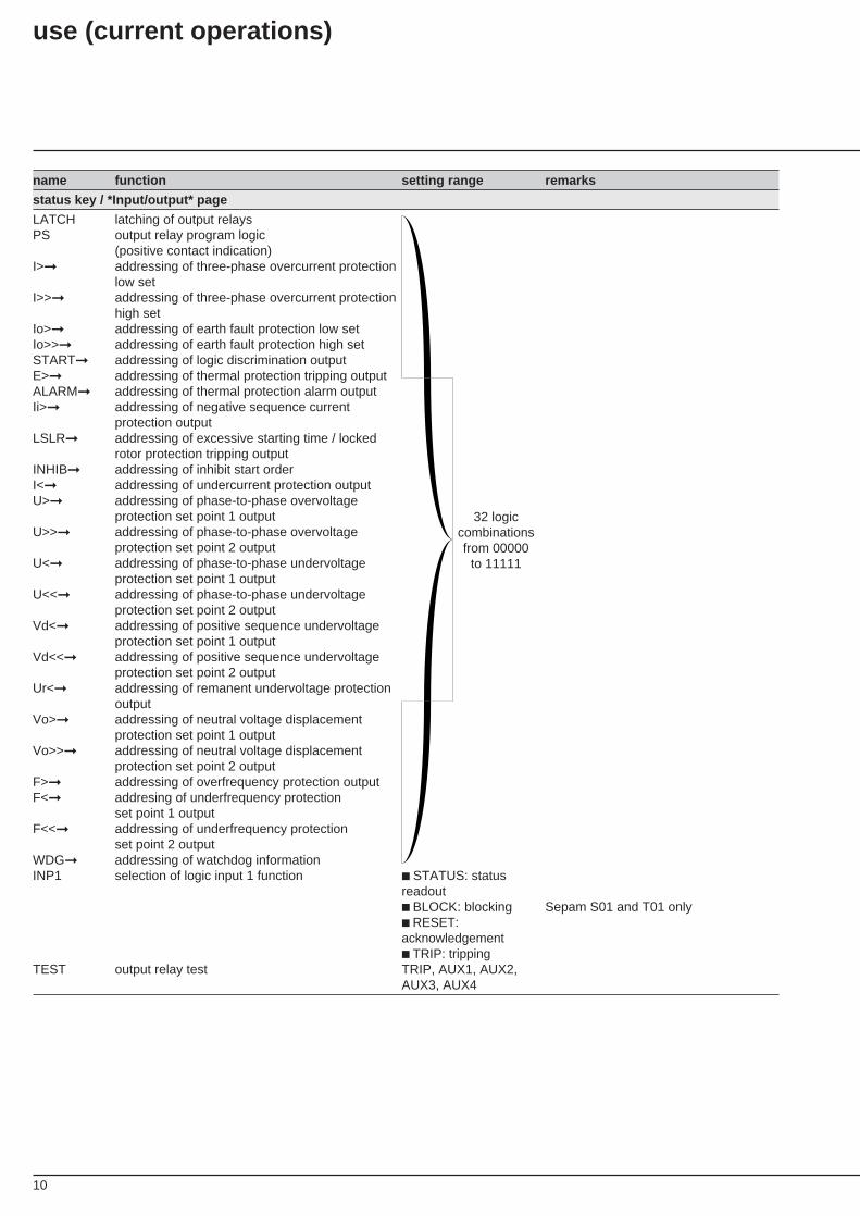
name function setting range remarks
status key / *Input/output* page
LATCH latching of output relaysPS output relay program logic
(positive contact indication)I>➞ addressing of three-phase overcurrent protection
low setI>>➞ addressing of three-phase overcurrent protection
high setIo>➞ addressing of earth fault protection low setIo>>➞ addressing of earth fault protection high setSTART➞ addressing of logic discrimination outputE>➞ addressing of thermal protection tripping outputALARM➞ addressing of thermal protection alarm outputIi>➞ addressing of negative sequence current
protection outputLSLR➞ addressing of excessive starting time / locked
rotor protection tripping outputINHIB➞ addressing of inhibit start orderI<➞ addressing of undercurrent protection outputU>➞ addressing of phase-to-phase overvoltage
protection set point 1 outputU>>➞ addressing of phase-to-phase overvoltage
protection set point 2 outputU<➞ addressing of phase-to-phase undervoltage
protection set point 1 outputU<<➞ addressing of phase-to-phase undervoltage
protection set point 2 outputVd<➞ addressing of positive sequence undervoltage
protection set point 1 outputVd<<➞ addressing of positive sequence undervoltage
protection set point 2 outputUr<➞ addressing of remanent undervoltage protection
outputVo>➞ addressing of neutral voltage displacement
protection set point 1 outputVo>>➞ addressing of neutral voltage displacement
protection set point 2 outputF>➞ addressing of overfrequency protection outputF<➞ addresing of underfrequency protection
set point 1 outputF<<➞ addressing of underfrequency protection
set point 2 outputWDG➞ addressing of watchdog informationINP1 selection of logic input 1 function ■ STATUS: status
readout■ BLOCK: blocking Sepam S01 and T01 only■ RESET:acknowledgement■ TRIP: tripping
TEST output relay test TRIP, AUX1, AUX2,AUX3, AUX4
32 logiccombinationsfrom 00000
to 11111
use (current operations)
11
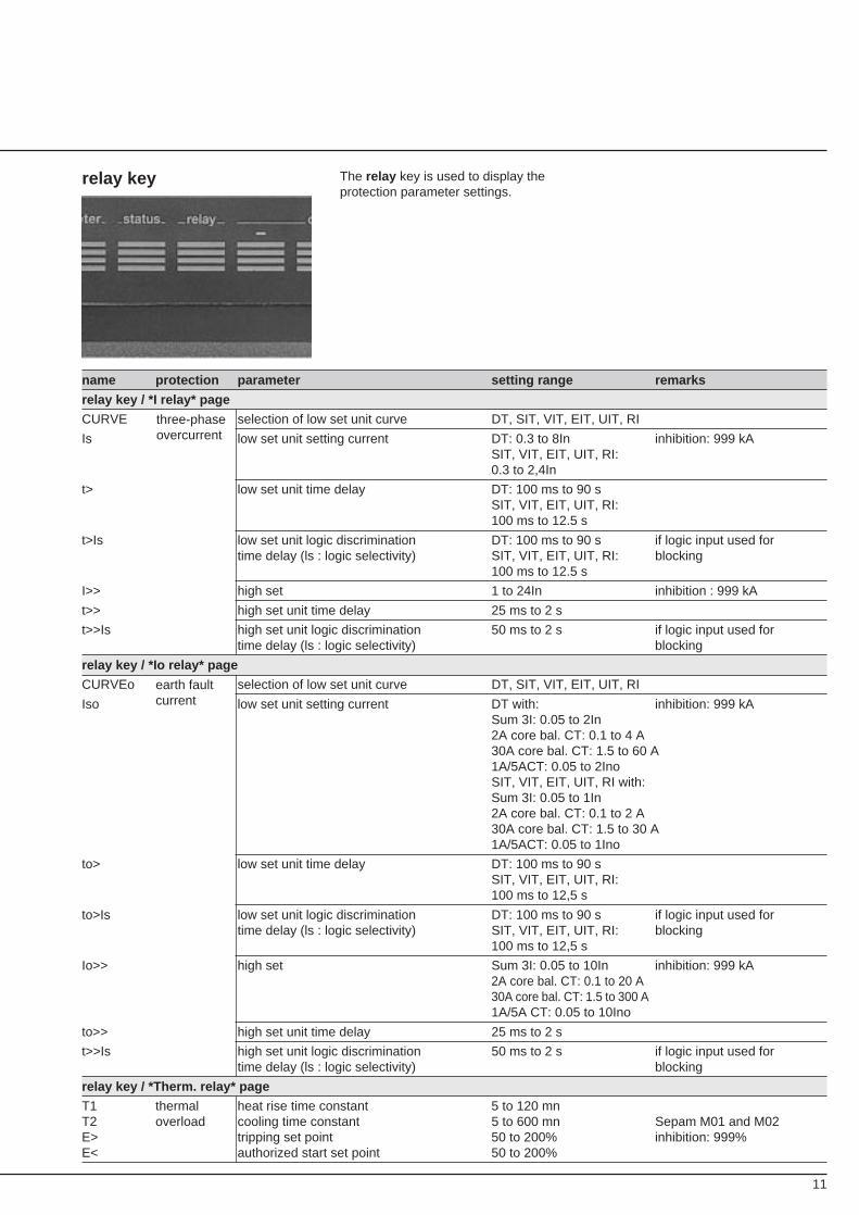
relay key The relay key is used to display theprotection parameter settings.
name protection parameter setting range remarks
relay key / *I relay* page
CURVE selection of low set unit curve DT, SIT, VIT, EIT, UIT, RI
Is low set unit setting current DT: 0.3 to 8In inhibition: 999 kASIT, VIT, EIT, UIT, RI:0.3 to 2,4In
t> low set unit time delay DT: 100 ms to 90 sSIT, VIT, EIT, UIT, RI:100 ms to 12.5 s
t>Is low set unit logic discrimination DT: 100 ms to 90 s if logic input used fortime delay (ls : logic selectivity) SIT, VIT, EIT, UIT, RI: blocking
100 ms to 12.5 s
I>> high set 1 to 24In inhibition : 999 kA
t>> high set unit time delay 25 ms to 2 s
t>>Is high set unit logic discrimination 50 ms to 2 s if logic input used fortime delay (ls : logic selectivity) blocking
relay key / *Io relay* page
CURVEo selection of low set unit curve DT, SIT, VIT, EIT, UIT, RI
Iso low set unit setting current DT with: inhibition: 999 kASum 3I: 0.05 to 2In2A core bal. CT: 0.1 to 4 A30A core bal. CT: 1.5 to 60 A1A/5ACT: 0.05 to 2InoSIT, VIT, EIT, UIT, RI with:Sum 3I: 0.05 to 1In2A core bal. CT: 0.1 to 2 A30A core bal. CT: 1.5 to 30 A1A/5ACT: 0.05 to 1Ino
to> low set unit time delay DT: 100 ms to 90 sSIT, VIT, EIT, UIT, RI:100 ms to 12,5 s
to>Is low set unit logic discrimination DT: 100 ms to 90 s if logic input used fortime delay (ls : logic selectivity) SIT, VIT, EIT, UIT, RI: blocking
100 ms to 12,5 s
Io>> high set Sum 3I: 0.05 to 10In inhibition: 999 kA2A core bal. CT: 0.1 to 20 A30A core bal. CT: 1.5 to 300 A1A/5A CT: 0.05 to 10Ino
to>> high set unit time delay 25 ms to 2 s
t>>Is high set unit logic discrimination 50 ms to 2 s if logic input used fortime delay (ls : logic selectivity) blocking
relay key / *Therm. relay* page
T1 thermal heat rise time constant 5 to 120 mnT2 overload cooling time constant 5 to 600 mn Sepam M01 and M02E> tripping set point 50 to 200% inhibition: 999%E< authorized start set point 50 to 200%
earth faultcurrent
three-phaseovercurrent
12
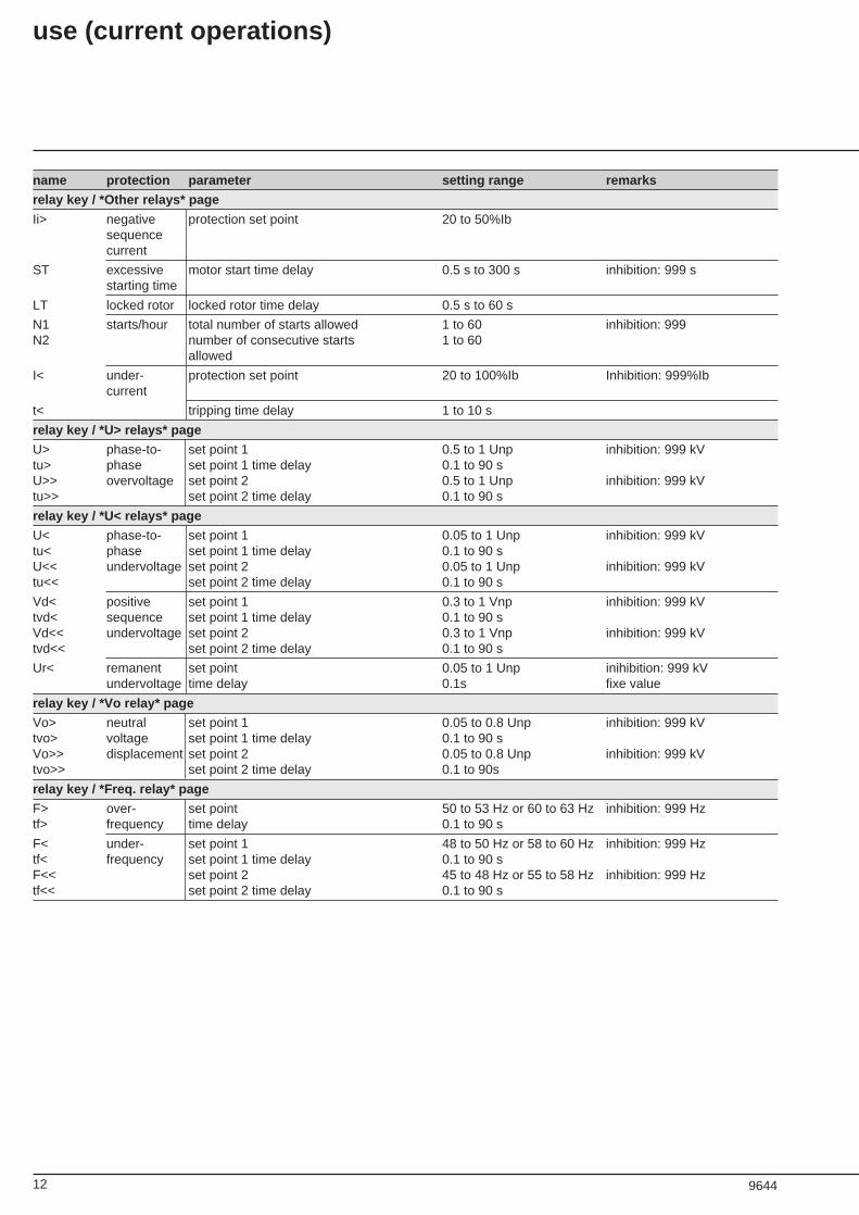
name protection parameter setting range remarks
relay key / *Other relays* page
Ii> negative protection set point 20 to 50%Ibsequencecurrent
ST excessive motor start time delay 0.5 s to 300 s inhibition: 999 sstarting time
LT locked rotor locked rotor time delay 0.5 s to 60 s
N1 starts/hour total number of starts allowed 1 to 60 inhibition: 999N2 number of consecutive starts 1 to 60
allowed
I< under- protection set point 20 to 100%Ib Inhibition: 999%Ibcurrent
t< tripping time delay 1 to 10 s
relay key / *U> relays* page
U> phase-to- set point 1 0.5 to 1 Unp inhibition: 999 kVtu> phase set point 1 time delay 0.1 to 90 sU>> overvoltage set point 2 0.5 to 1 Unp inhibition: 999 kVtu>> set point 2 time delay 0.1 to 90 s
relay key / *U< relays* page
U< phase-to- set point 1 0.05 to 1 Unp inhibition: 999 kVtu< phase set point 1 time delay 0.1 to 90 sU<< undervoltage set point 2 0.05 to 1 Unp inhibition: 999 kVtu<< set point 2 time delay 0.1 to 90 s
Vd< positive set point 1 0.3 to 1 Vnp inhibition: 999 kVtvd< sequence set point 1 time delay 0.1 to 90 sVd<< undervoltage set point 2 0.3 to 1 Vnp inhibition: 999 kVtvd<< set point 2 time delay 0.1 to 90 s
Ur< remanent set point 0.05 to 1 Unp inihibition: 999 kVundervoltage time delay 0.1s fixe value
relay key / *Vo relay* page
Vo> neutral set point 1 0.05 to 0.8 Unp inhibition: 999 kVtvo> voltage set point 1 time delay 0.1 to 90 sVo>> displacement set point 2 0.05 to 0.8 Unp inhibition: 999 kVtvo>> set point 2 time delay 0.1 to 90s
relay key / *Freq. relay* page
F> over- set point 50 to 53 Hz or 60 to 63 Hz inhibition: 999 Hztf> frequency time delay 0.1 to 90 s
F< under- set point 1 48 to 50 Hz or 58 to 60 Hz inhibition: 999 Hztf< frequency set point 1 time delay 0.1 to 90 sF<< set point 2 45 to 48 Hz or 55 to 58 Hz inhibition: 999 Hztf<< set point 2 time delay 0.1 to 90 s
9644
use (current operations)
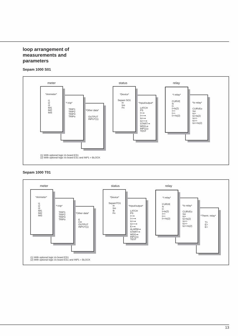
13
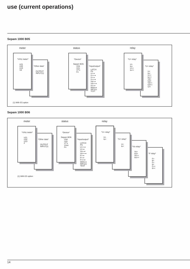
loop arrangement ofmeasurements andparameters
Sepam 1000 S01
Sepam 1000 T01
*Other data*
OUTPUTINPUT(1)
*I trip*
TRIP1TRIP2TRIP3TRIPo
*Ammeter*
I1I2I3IM1IM2IM3
*Input/output*
*Device*
Sepam SO1 In Ino Fn
*US relay*
U>tu>
LATCHPSI>➞I>>➞Io>➞Io>>➞START➞WDG➞INP1(1)TEST
meter status relay
(1) With optional logic i/o board ES1(2) With optional logic i/o board ES1 and INP1 = BLOCK
*I relay*
CURVEIst>t>Is(2)I>>t>>t>>Is(2)
*Io relay*
CURVEoIsoto>to>Is(2)Io>>to>>to>>Is(2)
*Other data*
ECHOUTPUTINPUT(1)
*I trip*
TRIP1TRIP2TRIP3TRIPo
*Ammeter*
I1I2I3IM1IM2IM3
*Input/output*
*Device*
SepamTO1 In Ino Ib Fn
*US relay*
U>tu>
LATCHPSI>➞I>>➞Io>➞Io>>➞E>➞ALARM➞START➞WDG➞INP1(1)TEST
meter status relay
(1) With optional logic i/o board ES1(2) With optional logic i/o board ES1 and INP1 = BLOCK
*I relay*
CURVEIst>t>Is(2)I>>t>>t>>Is(2)
*Io relay*
CURVEoIsoto>to>Is(2)Io>>to>>to>>Is(2)
*Therm. relay*
T1E>E<
14
Sepam 1000 B05
*Other data*
OUTPUTINPUT(1)
*V/Hz meter*
U21U32U13Vd
*Input/output*
LATCHPSU>➞U>>➞U<➞U<<➞Vd<➞Vd<<➞Ur<➞WDG➞INP1(1)TEST
*Device*
Sepam BO5 Unp Uns VT's Fn
*U< relay*
*U> relay*
U>tu>U>>tu>>
U<tu<U<<tu<<Vd<tvd<Vd<<tvd<<Ur<
meter status relay
(1) With ES option
Sepam 1000 B06
relay
*Other data*
OUTPUTINPUT(1)
*V/Hz meter*
U21U32U13F
*Input/output*
*Device*
Sepam BO6 Unp Uns VT's Vnso Fn
*Other data*
*US relay*
U>tu>
LATCHPSU>>➞U<➞Vo>➞Vo>>➞F>➞F<➞F<<➞WDG➞INP1(1)TEST
U<tu<U<<tu<<Vd<tvd<Vd<<tvd<<Ur<
meter
*F relay*
*Vo relay*
Vo>tvo>Vo>>tvo>>
F>tf>F<tf<F<<tf<<
status
(1) With ES option
*U< relay*
U<tu<
*U> relay*
U>tu>
use (current operations)
15
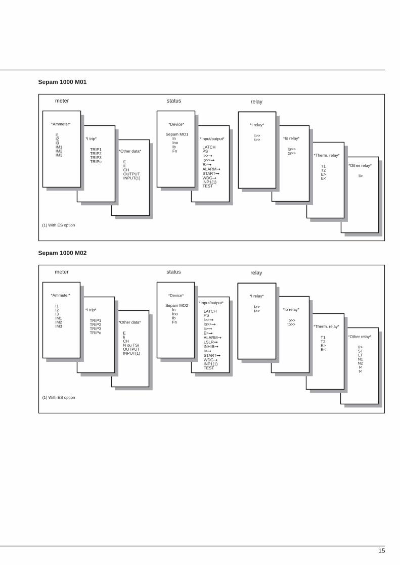
*Other data*
EIiCHN ou TSiOUTPUTINPUT(1)
*I trip*
TRIP1TRIP2TRIP3TRIPo
*Ammeter*
I1I2I3IM1IM2IM3
*Input/output*
*Device*
Sepam MO2 In Ino Ib Fn
*US relay*
U>tu>LATCH
PSI>>➞Io>>➞Ii>➞E>➞ALARM➞LSLR➞INHIB➞I<➞START➞WDG➞INP1(1)TEST
meter status relay
(1) With ES option
*I relay*
I>>t>> *Io relay*
Io>>to>> *Therm. relay*
T1T2E>E<
*Other relay*
Ii>STLTN1N2I<t<
Sepam 1000 M01
*Other data*
EIiCHOUTPUTINPUT(1)
*I trip*
TRIP1TRIP2TRIP3TRIPo
*Ammeter*
I1I2I3IM1IM2IM3
*Input/output*
*Device*
Sepam MO1 In Ino Ib Fn
*US relay*
U>tu>
LATCHPSI>>➞Io>>➞E>➞ALARM➞START➞WDG➞INP1(1)TEST
meter status relay
(1) With ES option
*I relay*
I>>t>> *Io relay*
Io>>to>> *Therm. relay*
T1T2E>E<
*Other relay*
Ii>
Sepam 1000 M02
16
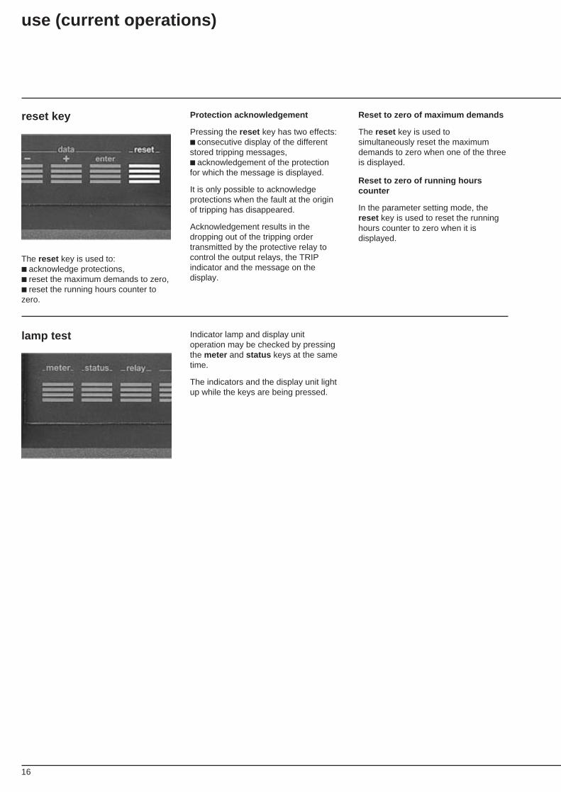
reset key Reset to zero of maximum demands
The reset key is used tosimultaneously reset the maximumdemands to zero when one of the threeis displayed.
Reset to zero of running hourscounter
In the parameter setting mode, thereset key is used to reset the runninghours counter to zero when it isdisplayed.
Protection acknowledgement
Pressing the reset key has two effects:■ consecutive display of the differentstored tripping messages,■ acknowledgement of the protectionfor which the message is displayed.
It is only possible to acknowledgeprotections when the fault at the originof tripping has disappeared.
Acknowledgement results in thedropping out of the tripping ordertransmitted by the protective relay tocontrol the output relays, the TRIPindicator and the message on thedisplay.
The reset key is used to:■ acknowledge protections,■ reset the maximum demands to zero,■ reset the running hours counter tozero.
lamp test Indicator lamp and display unitoperation may be checked by pressingthe meter and status keys at the sametime.
The indicators and the display unit lightup while the keys are being pressed.
use (current operations)
17
checking prior tocommissioning
These operations must be carried outbefore Sepam 1000 is energized.
Checks:
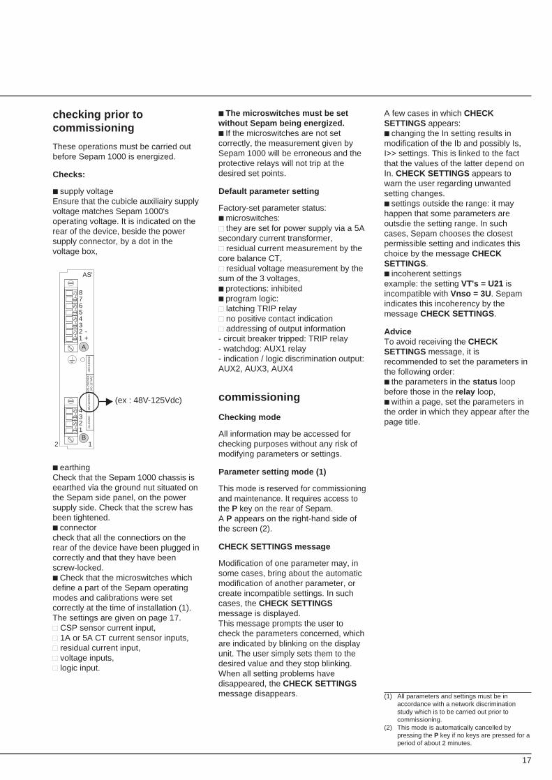
■ supply voltageEnsure that the cubicle auxiliairy supplyvoltage matches Sepam 1000'soperating voltage. It is indicated on therear of the device, beside the powersupply connector, by a dot in thevoltage box,
■ The microswitches must be setwithout Sepam being energized.■ If the microswitches are not setcorrectly, the measurement given bySepam 1000 will be erroneous and theprotective relays will not trip at thedesired set points.
Default parameter setting
Factory-set parameter status:■ microswitches:■■ they are set for power supply via a 5Asecondary current transformer,■■ residual current measurement by thecore balance CT,■■ residual voltage measurement by thesum of the 3 voltages,■ protections: inhibited■ program logic:■■ latching TRIP relay■■ no positive contact indication■■ addressing of output information- circuit breaker tripped: TRIP relay- watchdog: AUX1 relay- indication / logic discrimination output:AUX2, AUX3, AUX4
commissioning
Checking mode
All information may be accessed forchecking purposes without any risk ofmodifying parameters or settings.
Parameter setting mode (1)
This mode is reserved for commissioningand maintenance. It requires access tothe P key on the rear of Sepam.A P appears on the right-hand side ofthe screen (2).
CHECK SETTINGS message
Modification of one parameter may, insome cases, bring about the automaticmodification of another parameter, orcreate incompatible settings. In suchcases, the CHECK SETTINGSmessage is displayed.This message prompts the user tocheck the parameters concerned, whichare indicated by blinking on the displayunit. The user simply sets them to thedesired value and they stop blinking.When all setting problems havedisappeared, the CHECK SETTINGSmessage disappears.
A few cases in which CHECKSETTINGS appears:■ changing the In setting results inmodification of the Ib and possibly Is,I>> settings. This is linked to the factthat the values of the latter depend onIn. CHECK SETTINGS appears towarn the user regarding unwantedsetting changes.■ settings outside the range: it mayhappen that some parameters areoutsdie the setting range. In suchcases, Sepam chooses the closestpermissible setting and indicates thischoice by the message CHECKSETTINGS.■ incoherent settingsexample: the setting VT's = U21 isincompatible with Vnso = 3U . Sepamindicates this incoherency by themessage CHECK SETTINGS.
AdviceTo avoid receiving the CHECKSETTINGS message, it isrecommended to set the parameters inthe following order:■ the parameters in the status loopbefore those in the relay loop,■ within a page, set the parameters inthe order in which they appear after thepage title.
(1) All parameters and settings must be inaccordance with a network discriminationstudy which is to be carried out prior tocommissioning.
(2) This mode is automatically cancelled bypressing the P key if no keys are pressed for aperiod of about 2 minutes.
2 1
1 2 345678
+-
A
1 2 34
AS'
B
24-J
0VD
C48
V-1
25V
DC
220-
2500
VD
C10
0-12
7VA
C22
0-24
0VA
C
(ex : 48V-125Vdc)
■ earthingCheck that the Sepam 1000 chassis iseearthed via the ground nut situated onthe Sepam side panel, on the powersupply side. Check that the screw hasbeen tightened.■ connectorcheck that all the connectiors on therear of the device have been plugged incorrectly and that they have beenscrew-locked.■ Check that the microswitches whichdefine a part of the Sepam operatingmodes and calibrations were setcorrectly at the time of installation (1).The settings are given on page 17.■■ CSP sensor current input,■■ 1A or 5A CT current sensor inputs,■■ residual current input,■■ voltage inputs,■■ logic input.
18
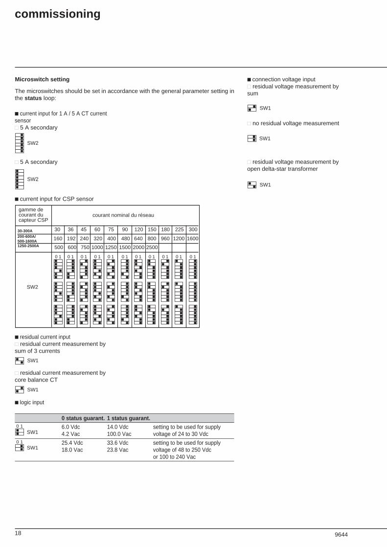
■ logic input
0 status guarant. 1 status guarant.
6.0 Vdc 14.0 Vdc setting to be used for supply4.2 Vac 100.0 Vac voltage of 24 to 30 Vdc
25.4 Vdc 33.6 Vdc setting to be used for supply18.0 Vac 23.8 Vac voltage of 48 to 250 Vdc
or 100 to 240 Vac
SW110
SW110
Microswitch setting
The microswitches should be set in accordance with the general parameter setting inthe status loop:
■ current input for 1 A / 5 A CT currentsensor■■ 5 A secondary
■ connection voltage input■■ residual voltage measurement bysum
SW1
■■ no residual voltage measurement
SW1
■■ residual voltage measurement byopen delta-star transformer
SW1
SW2
■■ 5 A secondary
SW2
■ current input for CSP sensor
0 10 10 10 10 10 10 10 10 10 10 1
gamme decourant ducapteur CSP
courant nominal du réseau
30-300 A 30 36 45 60 75 90 120 150 180 225 300
160-1600 A 160 192 240 320 400 480 640 800 960 1200 1600
500-2500 A 500 600 750 1000 1250 1500 2000 2500
SW2
■ residual current input■■ residual current measurement bysum of 3 currents
SW1
■■ residual current measurement bycore balance CT
SW1
commissioning
9644
30-300A200-600A/500-1600A1250-2500A
19
protection
According to the type of Sepam, thefollowing functions are available.
phase overcurrent(ANSI 50/51)
Three-phase protection of equipmentagainst overloads and phase-to-phaseshort circuits.
■ substation and transformerapplicationsThe protection includes two units:■■ low set unit, IDMT or definite time,■■ high set unit, definite time,instantaneous or time-delayed.Different characteristics for IDMTprotection: standard inverse time, veryinverse time, extremely inverse time,ultra inverse time and RI curve. Thewide range of time-delay settings evenprovides for the long time inverse (LTI)curve.
■ motor applicationsThe protection is limited to the definitetime high set unit.Recommendations:■■ set higher than starting current,■■ instantaneous operation if theequipment is controlled by a contactoror circuit breaker only,■■ time-delayed operation if theequipment is controlled by a contactor-fuse combination so that the fuse blowsbefore the contactor when the faultcurrent is greater than the contractor'sbreaking capacity.
earth fault(ANSI 50/51N or 50/51G)
■ connection and equipment earth faultprotectionEarth fault current detection can beprovided by:■■ the three phase current transformers,■■ a current transformer (1 A or 5 A),combined with a CSH30 interposingring CT,■■ a special-purpose core balance CT,CSH120 or CSH200 according to therequired diameter, this method beingthe most accurate one. The two ratingsavailable (2 A and 30 A) provide a verywide setting range.
■ transformer and substationapplicationsThe protection includes two units:■■ low set unit, IDMT or definite time,■■ high set unit, definite time,instantaneous or time-delayed.The characteristic curves are the sameas those for three-phase overcurrentprotection.
■ motor applicationsThe protection has a definite time highset.Recommendations:■■ connect to special-purpose CSH corebalance CT for greater sensitivity,■■ definite time operation.
thermal overload(ANSI 49)
Protection of equipment againstthermal damage caused by overloads.Thermal overload is calculatedaccording to an appropriatemathematical model to suit eachapplication.The function comprises:■■ an adjustable trip setting,■■ an adjustable restart authorizationsetting,■■ a fixed alarm setting.When a power failure occurs, the %thermal capacity used is reset to zero,unless the thermal overload protectiontripped before the outage. In suchcases, the initial thermal capacity usedvalue at the time of energizing is equalto the trip setting.To reset thermal capacity used to zero,there are two solutions:1 - wait for thermal capacity used todrop below set points E< and E>,acknowledge the protection and cut offthe auxiliary power supply,2 - disable the protection by setting E>to 999%, acknowledge it and cut off theauxiliary power supply.
■ transformer applicationsThe model includes the transformer'sheat rise time constant.
■ motor applicationsThe model includes two time constants:the heat rise constant, used when themotor is running, and the cooling timeconstant, used when the motor is shutdown. The model also includes theeffect of negative sequence current onrotor heating.
negative sequence / unbalance(ANSI 46)Protection of equipment againstoverheating caused by an unbalancedpower supply, phase inversion or phasebreak and against low levels ofovercurrent between 2 phases. IDMTtime curves.■ the negative sequence current iscalculated from I1 and I3, assumingthere is zero earth fault current.
locked rotor / excessive starting time(ANSI 48/51LR)
Protection of motors that are liable tostart with overloads or insufficient supplyvoltage and/or that drive loads that areliable to become locked (e.g. crushers).The locked rotor protection function isonly confirmed after a time delay thatcorresponds to the normal starting time.Recommendation:■■ short time operation.
starts per hour(ANSI 66)
Protection against overheating causedby too frequent starts.Checking of:■■ the number of starts per hour.■■ the number of consecutive starts.When the permissible limits arereached, the protection inhibits motorenergizing for a preset time period.
■ a power failure causes the completeloss of the record of starts, unless theoutage takes place during an inhibitedstart phase. In such cases, the waitingperiod, which is restored when thedevice is energized again, is equal tothe initial waiting period, stored at thetime the protection tripped. In all cases,the protection becomes fully operationalagain an hour after it is energized.
■ to totally erase the start-up record, 2cases may occur:■■ the limitation of the number of start-upsfunction is disabled (no prohibiting of thenumber of start-ups in progress), and theuser simply switches off the power supply.■■ the limitation of the number of start-ups function is activated (prohibiting ofthe number of start-ups in progress),and 2 solutions are possible:1 - wait until the end of the prohibitedstart-up period and switch off theauxiliary power supply,2 - disable the protection by setting N1to 999 and switch off the power supply.

20
undercurrent(ANSI 37)Pump protection against theconsequences of priming loss.The protection detects delayedundercurrent corresponding to motorno-load operation which is typical of aloss of pump priming.
overvoltage(ANSI 59)
Protecton against abnormally highvoltage and checking that there issufficient voltage for power supplychangeover (set point 1) andmonitoring of phase-to-phase voltagesU32 and U21 (set point 2).
positive sequence undervoltage(ANSI 27D)
Protection which prevents motormalfunctioning due to insufficient orunbalanced supply voltage.In order to use this protection, it isnecessary to connect Sepam to voltagetransformers to measure U21 and U32.
remanent undervoltage(ANSI 27R)Monitoring of the clearing of voltagesustained by rotating machines afterthe opening of the circuit. Theprotection is used with automaticchangeover functions to preventtransient electrical and mechanicalphenomena that are caused by fastresupply of power to motors. It monitorsphase-to-phase voltage U21.
phase-to-phase undervoltage(ANSI 27)
Protection used either for automaticcontrol (transfer, load shedding) or formotor protection against voltage sags.The protection monitors dips in each ofthe phase-to-phase voltages measured.
neutral voltage displacement(ANSI 59N)Detection of insulation faults inungrounded systems by measurementof neutral voltage displacement.This protection is generally used fortransformer incomers or busbars.
overfrequency(ANSI 81)
Protection against abnormally highfrequency.
underfrequency(ANSI 81)
Detection of variances with respect tothe rated frequency, in order tomaintain high quality power supply.This protection can be used for overalltripping or for load shedding.
commissioning
21
program logic
Sepam 1000 output operationparameters may all be set via thekeyboard.Operation is defined by:■ addressing of the internal informationon the output relays,■ relay latching (function 86),■ program logic (with or without positivecontact indication).The default setting configurationdetailed below is appropriate for mostapplications. In such cases, Sepam isready to be used and it is notnecessary to modify the parametersdescribed in this section.All the information given in this sectionapplies, regardless of the number ofSepam outputs (2 or 5 according towhether or not Sepam includes theoptional ES1 input/output board.
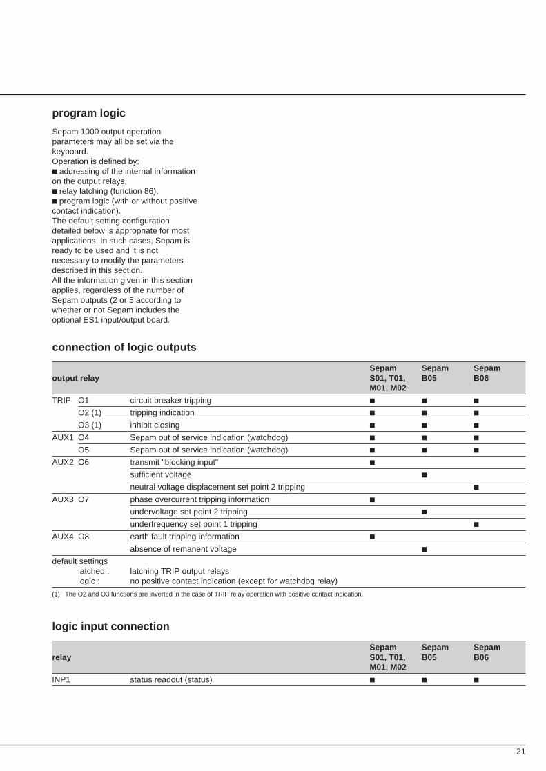
connection of logic outputs
Sepam Sepam Sepamoutput relay S01, T01, B05 B06
M01, M02
TRIP O1 circuit breaker tripping ■ ■ ■
O2 (1) tripping indication ■ ■ ■
O3 (1) inhibit closing ■ ■ ■
AUX1 O4 Sepam out of service indication (watchdog) ■ ■ ■
O5 Sepam out of service indication (watchdog) ■ ■ ■
AUX2 O6 transmit "blocking input" ■
sufficient voltage ■
neutral voltage displacement set point 2 tripping ■
AUX3 O7 phase overcurrent tripping information ■
undervoltage set point 2 tripping ■
underfrequency set point 1 tripping ■
AUX4 O8 earth fault tripping information ■
absence of remanent voltage ■
default settingslatched : latching TRIP output relayslogic : no positive contact indication (except for watchdog relay)
(1) The O2 and O3 functions are inverted in the case of TRIP relay operation with positive contact indication.
logic input connection
Sepam Sepam Sepamrelay S01, T01, B05 B06
M01, M02
INP1 status readout (status) ■ ■ ■
22
modification of programlogicFor applications for which the programlogic programmed by default is notappropriate, it is possible to obtain thedesired configuration by parametersetting.
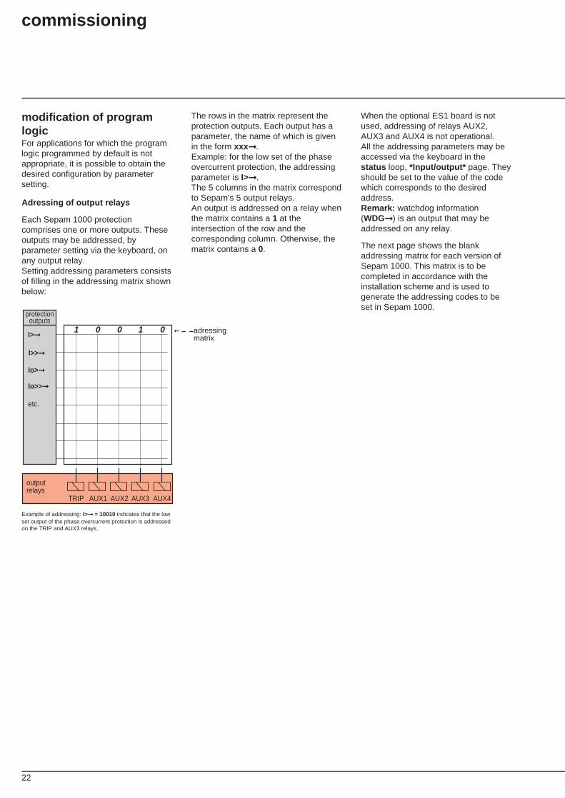
Adressing of output relays
Each Sepam 1000 protectioncomprises one or more outputs. Theseoutputs may be addressed, byparameter setting via the keyboard, onany output relay.Setting addressing parameters consistsof filling in the addressing matrix shownbelow:
The rows in the matrix represent theprotection outputs. Each output has aparameter, the name of which is givenin the form xxx ➞.Example: for the low set of the phaseovercurrent protection, the addressingparameter is I>➞.The 5 columns in the matrix correspondto Sepam's 5 output relays.An output is addressed on a relay whenthe matrix contains a 1 at theintersection of the row and thecorresponding column. Otherwise, thematrix contains a 0.
When the optional ES1 board is notused, addressing of relays AUX2,AUX3 and AUX4 is not operational.All the addressing parameters may beaccessed via the keyboard in thestatus loop, *Input/output* page. Theyshould be set to the value of the codewhich corresponds to the desiredaddress.Remark: watchdog information(WDG➞) is an output that may beaddressed on any relay.
The next page shows the blankaddressing matrix for each version ofSepam 1000. This matrix is to becompleted in accordance with theinstallation scheme and is used togenerate the addressing codes to beset in Sepam 1000.
1 0 0 1 0
outputrelays
TRIP AUX1 AUX2 AUX3 AUX4
➞ adressingmatrix
I>>➞
Io>➞
etc.
I>➞
Io>>➞
protection outputs
Example of addressing: I>➞ = 10010 indicates that the lowset output of the phase overcurrent protection is addressedon the TRIP and AUX3 relays.
commissioning
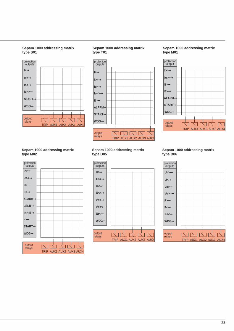
23
Sepam 1000 addressing matrixtype S01
Sepam 1000 addressing matrixtype T01
Sepam 1000 addressing matrixtype M01
I>>➞
Io>➞
START➞
WDG➞
outputrelays
TRIP AUX1 AUX2
protectionoutputs
I>➞
Io>>➞
AUX4AUX3
I>>➞
Io>➞
E>➞
ALARM ➞
START➞
WDG➞
outputrelays
TRIP AUX1 AUX2 AUX3 AUX4
I>➞
Io>>➞
protectionoutputs
outputrelays
I>>➞
Io>>➞
Ii>➞
E>➞
ALARM ➞
START➞
WDG➞
TRIP AUX1 AUX2 AUX3 AUX4
protectionoutput
Sepam 1000 addressing matrixtype M02
Sepam 1000 addressing matrixtype B05
Sepam 1000 addressing matrixtype B06
I>>➞
Io>>➞
Ii>➞
E>➞
ALARM ➞
LSLR➞
INHIB➞
I<➞
START➞
WDG➞
outputrelays
TRIP AUX1 AUX2 AUX3 AUX4
protectionoutputs
U>>➞
U<➞
Vd<➞
Vd<<➞
Ur<➞
WDG➞
outputrelays
TRIP AUX1 AUX2 AUX3 AUX4
U>➞
U<<➞
protectionoutputs
U<➞
Vo>➞
F>➞
F<➞
F<<➞
WDG➞
outputrelays
TRIP AUX1 AUX2 AUX3 AUX4
U>>➞
Vo>>➞
protectionoutputs
24
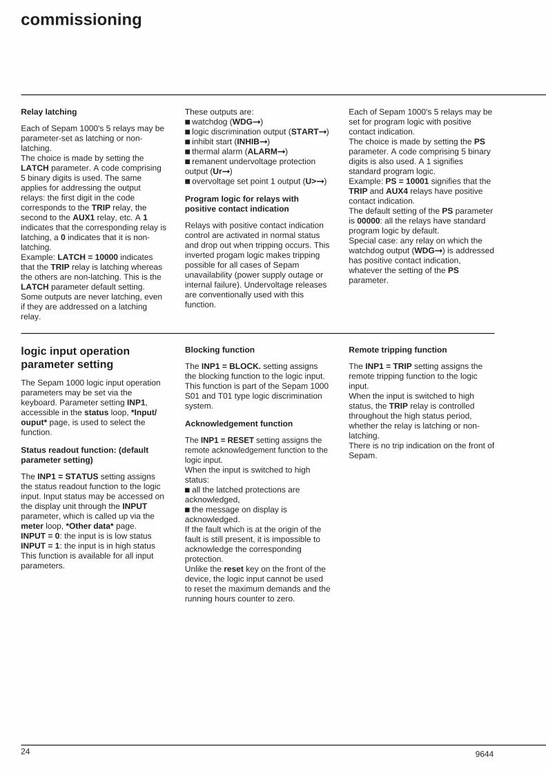
Relay latching
Each of Sepam 1000's 5 relays may beparameter-set as latching or non-latching.The choice is made by setting theLATCH parameter. A code comprising5 binary digits is used. The sameapplies for addressing the outputrelays: the first digit in the codecorresponds to the TRIP relay, thesecond to the AUX1 relay, etc. A 1indicates that the corresponding relay islatching, a 0 indicates that it is non-latching.Example: LATCH = 10000 indicatesthat the TRIP relay is latching whereasthe others are non-latching. This is theLATCH parameter default setting.Some outputs are never latching, evenif they are addressed on a latchingrelay.
These outputs are:■ watchdog (WDG➞)■ logic discrimination output (START➞)■ inhibit start (INHIB➞)■ thermal alarm (ALARM ➞)■ remanent undervoltage protectionoutput (Ur➞)■ overvoltage set point 1 output (U>➞)
Program logic for relays withpositive contact indication
Relays with positive contact indicationcontrol are activated in normal statusand drop out when tripping occurs. Thisinverted progam logic makes trippingpossible for all cases of Sepamunavailability (power supply outage orinternal failure). Undervoltage releasesare conventionally used with thisfunction.
Each of Sepam 1000's 5 relays may beset for program logic with positivecontact indication.The choice is made by setting the PSparameter. A code comprising 5 binarydigits is also used. A 1 signifiesstandard program logic.Example: PS = 10001 signifies that theTRIP and AUX4 relays have positivecontact indication.The default setting of the PS parameteris 00000: all the relays have standardprogram logic by default.Special case: any relay on which thewatchdog output (WDG➞) is addressedhas positive contact indication,whatever the setting of the PSparameter.
logic input operationparameter setting
The Sepam 1000 logic input operationparameters may be set via thekeyboard. Parameter setting INP1,accessible in the status loop, *Input/ouput* page, is used to select thefunction.
Status readout function: (defaultparameter setting)
The INP1 = STATUS setting assignsthe status readout function to the logicinput. Input status may be accessed onthe display unit through the INPUTparameter, which is called up via themeter loop, *Other data* page.INPUT = 0: the input is is low statusINPUT = 1: the input is in high statusThis function is available for all inputparameters.
Blocking function
The INP1 = BLOCK. setting assignsthe blocking function to the logic input.This function is part of the Sepam 1000S01 and T01 type logic discriminationsystem.
Acknowledgement function
The INP1 = RESET setting assigns theremote acknowledgement function to thelogic input.When the input is switched to highstatus:c all the latched protections areacknowledged,c the message on display isacknowledged.If the fault which is at the origin of thefault is still present, it is impossible toacknowledge the correspondingprotection.Unlike the reset key on the front of thedevice, the logic input cannot be usedto reset the maximum demands and therunning hours counter to zero.
Remote tripping function
The INP1 = TRIP setting assigns theremote tripping function to the logicinput.When the input is switched to highstatus, the TRIP relay is controlledthroughout the high status period,whether the relay is latching or non-latching.There is no trip indication on the front ofSepam.
commissioning
9644
25
maintenance
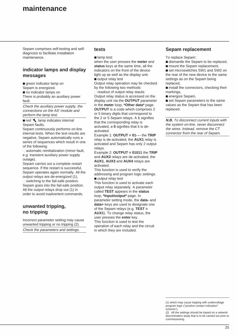
Sepam comprises self-testing and self-diagnosis to facilitate installationmaintenance.
indicator lamps and displaymessages
■ green indicator lamp onSepam is energized.■ no indicator lamps onThere is probably an auxiliary powerfault.
Check the auxiliary power supply, theconnections on the AS' module andperform the lamp test.
■ red lamp indicates internalSepam faults.Sepam continuously performs on-lineinternal tests. When the test results arenegative, Sepam automatically runs aseries of sequences which result in oneof the following:■■ automatic reinitialization (minor fault,e.g. transient auxiliary power supplyoutage).Sepam carries out a complete restartsequence. If the restart is successful,Sepam operates again normally. All theoutput relays are de-energized (1),■■ switching to the fail-safe position.Sepam goes into the fail-safe position.All the output relays drop out (1) inorder to avoid inadvertent commands.
unwanted tripping,no tripping
Incorrect parameter setting may causeunwanted tripping or no tripping (2).
Check the parameters and settings.
tests
■ lamp test:when the user presses the meter andstatus keys at the same time, all theindicators on the front of the devicelight up as well as the display unit.■ output relay testOutput relay operation may be checkedby the following two methods:■■ readout of output relay stauts:Output relay status is accessed on thedisplay unit via the OUTPUT parameterin the meter loop, *Other data* page.OUTPUT is a code which comprises 2or 5 binary digits that corrrespond tothe 2 or 5 Sepam relays. A 1 signifiesthat the corresponding relay isactivated, a 0 signifies that it is de-activated.Example 1: OUTPUT = 01- - - the TRIPrelay is de-activated, the AUX1 relay isactivated and Sepam has only 2 outputrelays.Example 2: OUTPUT = 01011 the TRIPand AUX2 relays are de-activated, theAUX1, AUX3 and AUX4 relays areactivated.This function is used to verify theaddressing and program logic settings.■ output relay testThis function is used to activate eachoutput relay separately. A parametercalled TEST appears in the statusloop, *Input/output* page. Inparameter setting mode, the data- anddata+ keys are used to designate oneof the Sepam relays (e.g. TEST =AUX1). To change relay status, theuser presses the enter key.This function is used to test theoperation of each relay and the circuitin which they are included.
Sepam replacement
To replace Sepam:■ dismantle the Sepam to be replaced,■ mount the Sepam replacement,■ set microswitches SW1 and SW2 onthe rear of the new device to the samesettings as on the Sepam beingreplaced,■ install the connectors, checking theirmarkings,■ energize Sepam,■ set Sepam parameters to the samevalues as the Sepam that has beenreplaced.
(1) which may cause tripping with undervoltageprogram logic ("positive contact indication"scheme").(2) All the settings should be based on a networkdiscrimination study that is to be carried out prior tocommissioning.
N.B. To disconnect current inputs withthe system on-line, never disconnectthe wires. Instead, remove the CTconnector from the rear of Sepam.
26
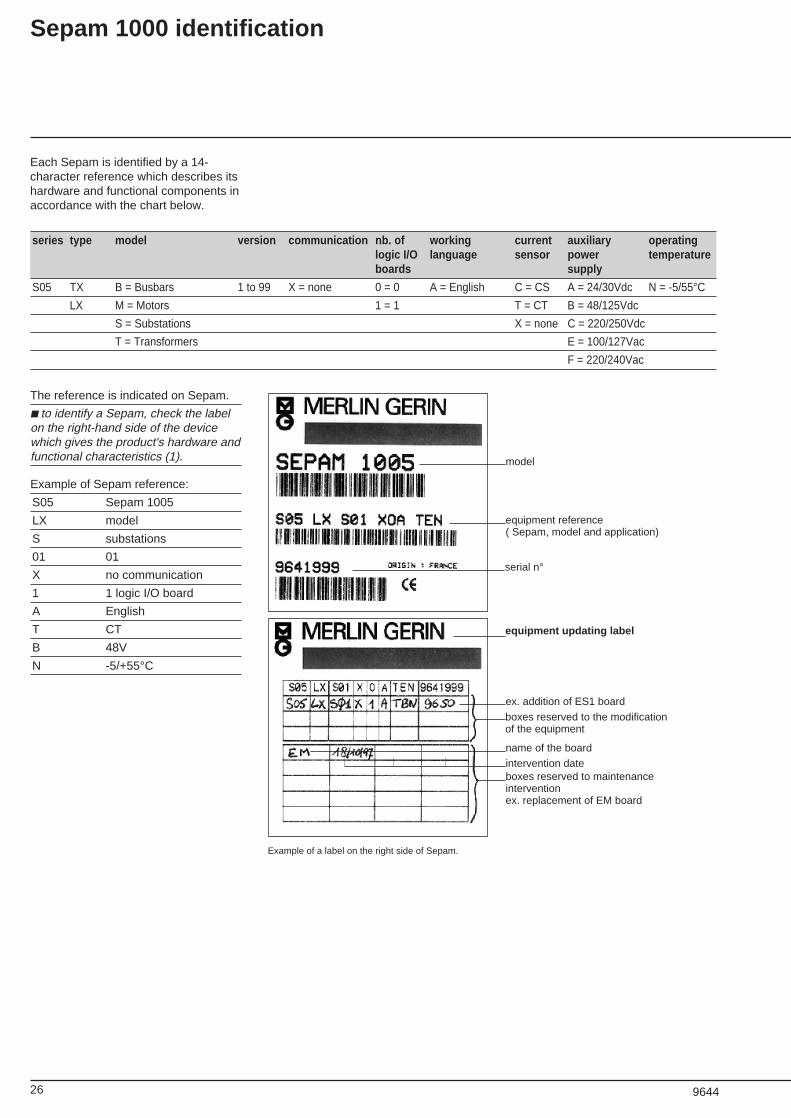
Each Sepam is identified by a 14-character reference which describes itshardware and functional components inaccordance with the chart below.
Sepam 1000 identification
series type model version communication nb. of working current auxiliary operatinglogic I/O language sensor power temperatureboards supply
S05 TX B = Busbars 1 to 99 X = none 0 = 0 A = English C = CS A = 24/30Vdc N = -5/55°CLX M = Motors 1 = 1 T = CT B = 48/125Vdc
S = Substations X = none C = 220/250Vdc
T = Transformers E = 100/127Vac
F = 220/240Vac
The reference is indicated on Sepam.
■ to identify a Sepam, check the labelon the right-hand side of the devicewhich gives the product's hardware andfunctional characteristics (1).
Example of Sepam reference:
S05 Sepam 1005
LX model
S substations
01 01
X no communication
1 1 logic I/O board
A English
T CT
B 48V
N -5/+55°C
ex. addition of ES1 board
name of the board
intervention dateboxes reserved to maintenanceinterventionex. replacement of EM board
serial n°
model
equipment reference( Sepam, model and application)
Example of a label on the right side of Sepam.
equipment updating label
boxes reserved to the modificationof the equipment
9644
27
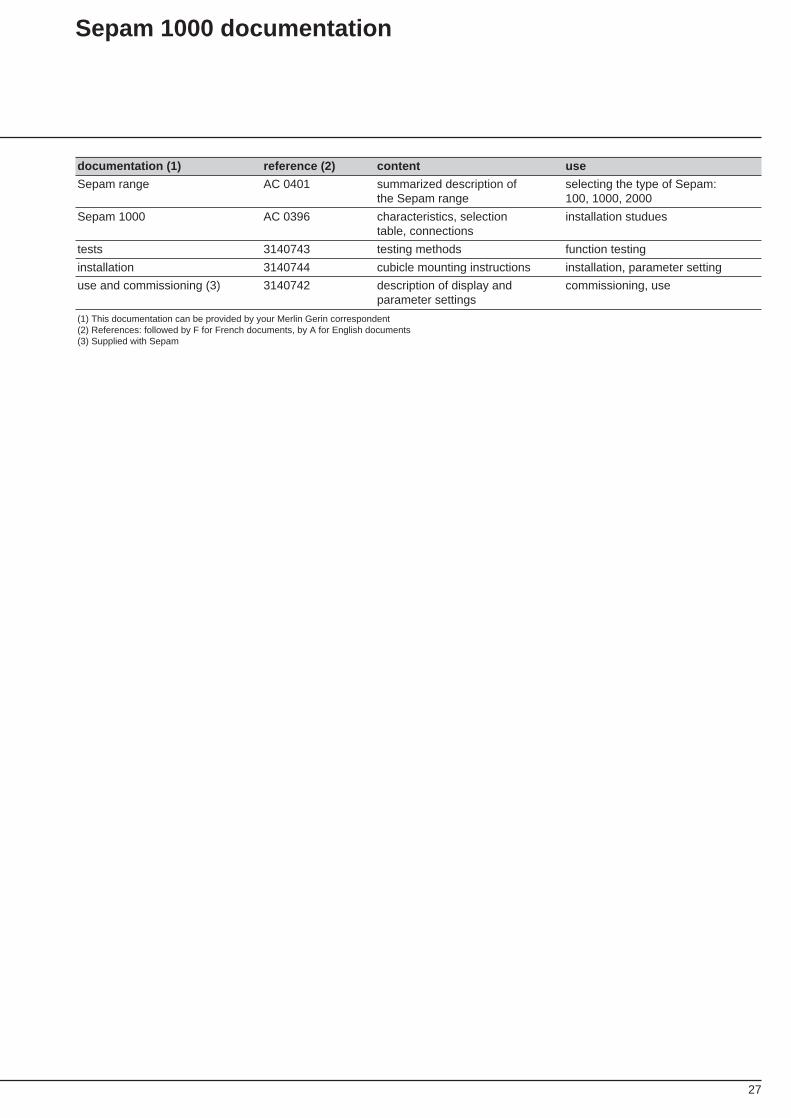
Sepam 1000 documentation
documentation (1) reference (2) content use
Sepam range AC 0401 summarized description of selecting the type of Sepam:the Sepam range 100, 1000, 2000
Sepam 1000 AC 0396 characteristics, selection installation studuestable, connections
tests 3140743 testing methods function testing
installation 3140744 cubicle mounting instructions installation, parameter setting
use and commissioning (3) 3140742 description of display and commissioning, useparameter settings
(1) This documentation can be provided by your Merlin Gerin correspondent(2) References: followed by F for French documents, by A for English documents(3) Supplied with Sepam

28
Schneider Electric SA
3140742A-BART. 75438
As standards, specifications and designs developfrom time to time, always ask for confirmation ofthe information given in this publication.
Publishing: Schneider Electric SADesign, production: SodipePrinting:
11 / 1996
Postal addressF - 38050 Grenoble cedex 9tél : (33) 04 76 57 60 60télex : merge 320842 F