Embed Size (px)
Citation preview
1
Document No. 75209019A RevD
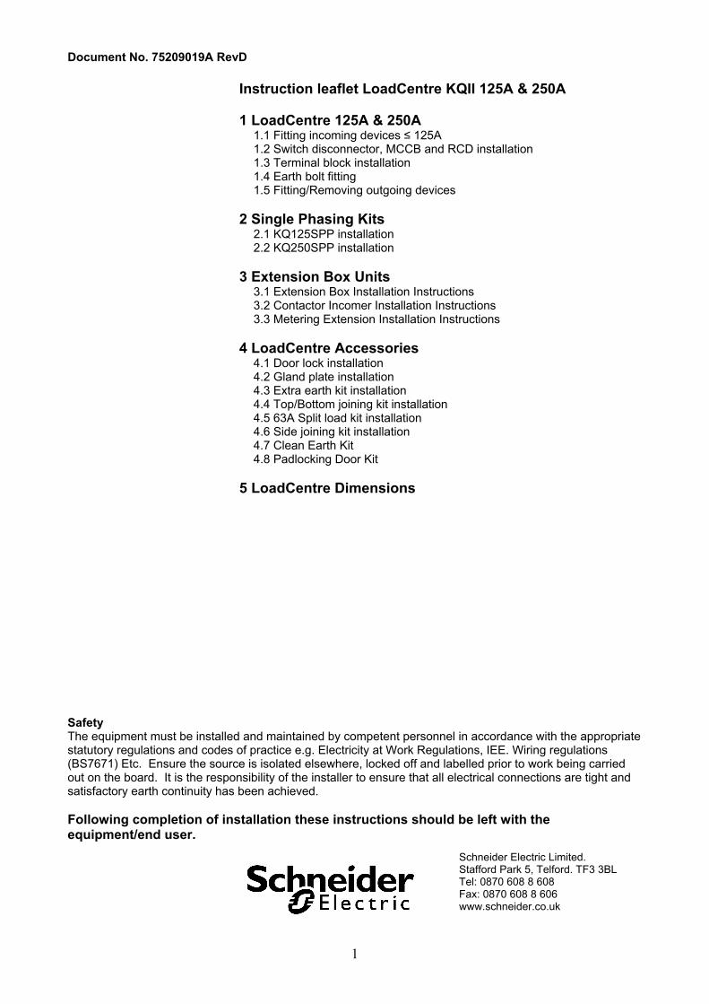
Instruction leaflet LoadCentre KQII 125A & 250A 1 LoadCentre 125A & 250A
1.1 Fitting incoming devices ≤ 125A 1.2 Switch disconnector, MCCB and RCD installation 1.3 Terminal block installation 1.4 Earth bolt fitting 1.5 Fitting/Removing outgoing devices
2 Single Phasing Kits
2.1 KQ125SPP installation 2.2 KQ250SPP installation
3 Extension Box Units
3.1 Extension Box Installation Instructions 3.2 Contactor Incomer Installation Instructions 3.3 Metering Extension Installation Instructions
4 LoadCentre Accessories
4.1 Door lock installation 4.2 Gland plate installation 4.3 Extra earth kit installation 4.4 Top/Bottom joining kit installation 4.5 63A Split load kit installation 4.6 Side joining kit installation 4.7 Clean Earth Kit 4.8 Padlocking Door Kit
5 LoadCentre Dimensions
Safety The equipment must be installed and maintained by competent personnel in accordance with the appropriate statutory regulations and codes of practice e.g. Electricity at Work Regulations, IEE. Wiring regulations (BS7671) Etc. Ensure the source is isolated elsewhere, locked off and labelled prior to work being carried out on the board. It is the responsibility of the installer to ensure that all electrical connections are tight and satisfactory earth continuity has been achieved.
Following completion of installation these instructions should be left with the equipment/end user.
Schneider Electric Limited. Stafford Park 5, Telford. TF3 3BL Tel: 0870 608 8 608 Fax: 0870 608 8 606 www.schneider.co.uk
2
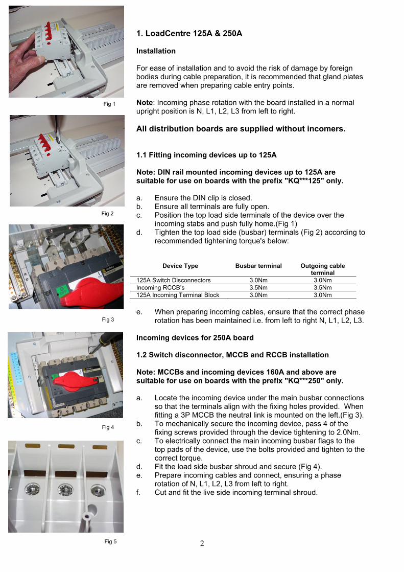
1. LoadCentre 125A & 250A Installation For ease of installation and to avoid the risk of damage by foreign bodies during cable preparation, it is recommended that gland plates are removed when preparing cable entry points. Note: Incoming phase rotation with the board installed in a normal upright position is N, L1, L2, L3 from left to right. All distribution boards are supplied without incomers. 1.1 Fitting incoming devices up to 125A Note: DIN rail mounted incoming devices up to 125A are suitable for use on boards with the prefix "KQ***125" only. a. Ensure the DIN clip is closed. b. Ensure all terminals are fully open. c. Position the top load side terminals of the device over the
incoming stabs and push fully home.(Fig 1) d. Tighten the top load side (busbar) terminals (Fig 2) according to
recommended tightening torque's below:
Device Type Busbar terminal Outgoing cable terminal
125A Switch Disconnectors 3.0Nm 3.0Nm Incoming RCCB’s 3.5Nm 3.5Nm 125A Incoming Terminal Block 3.0Nm 3.0Nm e. When preparing incoming cables, ensure that the correct phase
rotation has been maintained i.e. from left to right N, L1, L2, L3.
Incoming devices for 250A board 1.2 Switch disconnector, MCCB and RCCB installation Note: MCCBs and incoming devices 160A and above are suitable for use on boards with the prefix "KQ***250" only. a. Locate the incoming device under the main busbar connections
so that the terminals align with the fixing holes provided. When fitting a 3P MCCB the neutral link is mounted on the left.(Fig 3).
b. To mechanically secure the incoming device, pass 4 of the fixing screws provided through the device tightening to 2.0Nm.
c. To electrically connect the main incoming busbar flags to the top pads of the device, use the bolts provided and tighten to the correct torque.
d. Fit the load side busbar shroud and secure (Fig 4). e. Prepare incoming cables and connect, ensuring a phase
rotation of N, L1, L2, L3 from left to right. f. Cut and fit the live side incoming terminal shroud.
Fig 1
Fig 2
Fig 3
Fig 4
Fig 5
3
Possible incomers with tightening torque's are: Device Description Cable Lug Tunnel
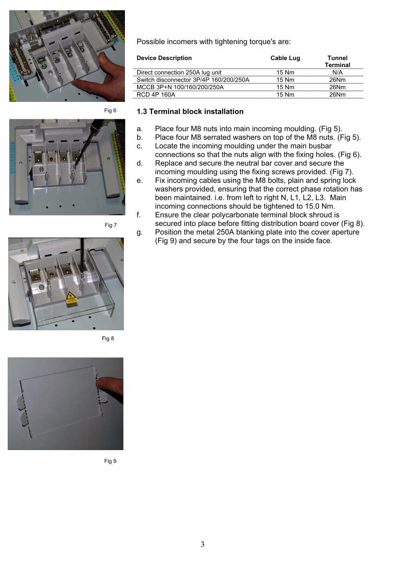
Terminal Direct connection 250A lug unit 15 Nm N/A Switch disconnector 3P/4P 160/200/250A 15 Nm 26Nm MCCB 3P+N 100/160/200/250A 15 Nm 26Nm RCD 4P 160A 15 Nm 26Nm 1.3 Terminal block installation a. Place four M8 nuts into main incoming moulding. (Fig 5). b. Place four M8 serrated washers on top of the M8 nuts. (Fig 5). c. Locate the incoming moulding under the main busbar
connections so that the nuts align with the fixing holes. (Fig 6). d. Replace and secure the neutral bar cover and secure the
incoming moulding using the fixing screws provided. (Fig 7). e. Fix incoming cables using the M8 bolts, plain and spring lock
washers provided, ensuring that the correct phase rotation has been maintained. i.e. from left to right N, L1, L2, L3. Main incoming connections should be tightened to 15.0 Nm.
f. Ensure the clear polycarbonate terminal block shroud is secured into place before fitting distribution board cover (Fig 8).
g. Position the metal 250A blanking plate into the cover aperture (Fig 9) and secure by the four tags on the inside face.
Fig 6
Fig 7
Fig 8
Fig 9
4
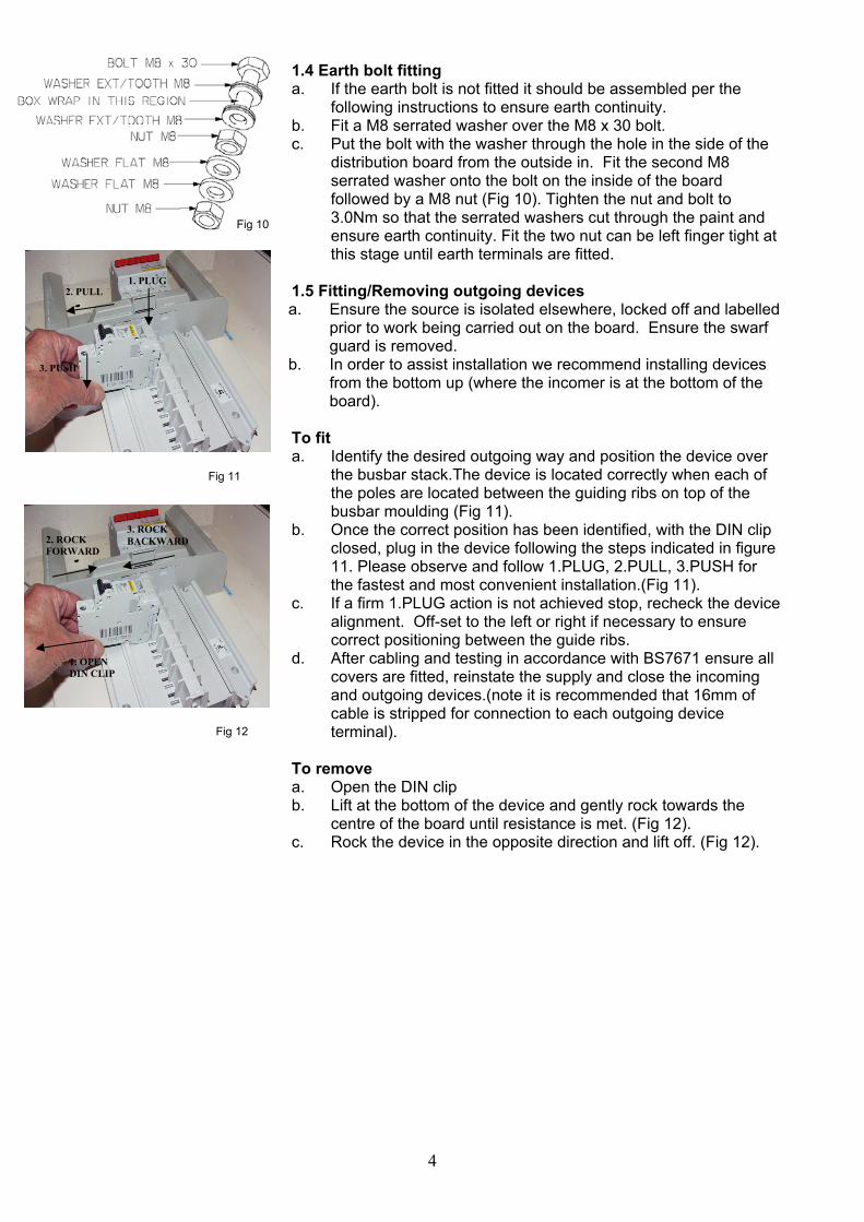
1.4 Earth bolt fitting a. If the earth bolt is not fitted it should be assembled per the
following instructions to ensure earth continuity. b. Fit a M8 serrated washer over the M8 x 30 bolt. c. Put the bolt with the washer through the hole in the side of the
distribution board from the outside in. Fit the second M8 serrated washer onto the bolt on the inside of the board followed by a M8 nut (Fig 10). Tighten the nut and bolt to 3.0Nm so that the serrated washers cut through the paint and ensure earth continuity. Fit the two nut can be left finger tight at this stage until earth terminals are fitted.
1.5 Fitting/Removing outgoing devices a. Ensure the source is isolated elsewhere, locked off and labelled
prior to work being carried out on the board. Ensure the swarf guard is removed.
b. In order to assist installation we recommend installing devices from the bottom up (where the incomer is at the bottom of the board).
To fit a. Identify the desired outgoing way and position the device over
the busbar stack.The device is located correctly when each of the poles are located between the guiding ribs on top of the busbar moulding (Fig 11).
b. Once the correct position has been identified, with the DIN clip closed, plug in the device following the steps indicated in figure 11. Please observe and follow 1.PLUG, 2.PULL, 3.PUSH for the fastest and most convenient installation.(Fig 11).
c. If a firm 1.PLUG action is not achieved stop, recheck the device alignment. Off-set to the left or right if necessary to ensure correct positioning between the guide ribs.
d. After cabling and testing in accordance with BS7671 ensure all covers are fitted, reinstate the supply and close the incoming and outgoing devices.(note it is recommended that 16mm of cable is stripped for connection to each outgoing device terminal).
To remove a. Open the DIN clip b. Lift at the bottom of the device and gently rock towards the
centre of the board until resistance is met. (Fig 12). c. Rock the device in the opposite direction and lift off. (Fig 12).
Fig 10
Fig 11
Fig 12
1. PLUG 2. PULL
3. PUSH
3. ROCK BACKWARD 2. ROCK
FORWARD
1. OPEN DIN CLIP
5
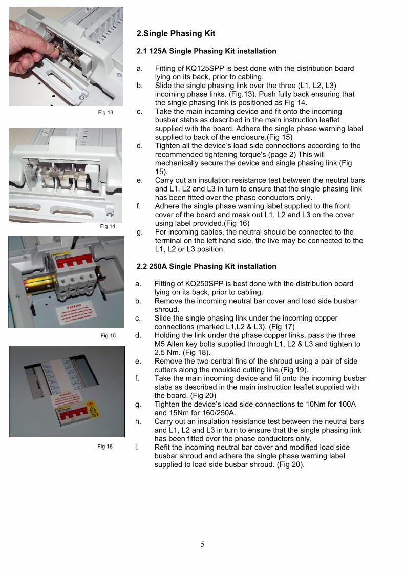
2.Single Phasing Kit 2.1 125A Single Phasing Kit installation a. Fitting of KQ125SPP is best done with the distribution board
lying on its back, prior to cabling. b. Slide the single phasing link over the three (L1, L2, L3)
incoming phase links. (Fig.13). Push fully back ensuring that the single phasing link is positioned as Fig 14.
c. Take the main incoming device and fit onto the incoming busbar stabs as described in the main instruction leaflet supplied with the board. Adhere the single phase warning label supplied to back of the enclosure.(Fig 15)
d. Tighten all the device’s load side connections according to the recommended tightening torque's (page 2) This will mechanically secure the device and single phasing link (Fig 15).
e. Carry out an insulation resistance test between the neutral bars and L1, L2 and L3 in turn to ensure that the single phasing link has been fitted over the phase conductors only.
f. Adhere the single phase warning label supplied to the front cover of the board and mask out L1, L2 and L3 on the cover using label provided.(Fig 16)
g. For incoming cables, the neutral should be connected to the terminal on the left hand side, the live may be connected to the L1, L2 or L3 position.
2.2 250A Single Phasing Kit installation a. Fitting of KQ250SPP is best done with the distribution board
lying on its back, prior to cabling. b. Remove the incoming neutral bar cover and load side busbar
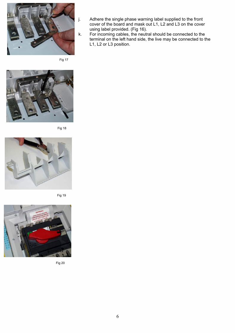
shroud. c. Slide the single phasing link under the incoming copper
connections (marked L1,L2 & L3). (Fig 17) d. Holding the link under the phase copper links, pass the three
M5 Allen key bolts supplied through L1, L2 & L3 and tighten to 2.5 Nm. (Fig 18).
e. Remove the two central fins of the shroud using a pair of side cutters along the moulded cutting line.(Fig 19).
f. Take the main incoming device and fit onto the incoming busbar stabs as described in the main instruction leaflet supplied with the board. (Fig 20)
g. Tighten the device’s load side connections to 10Nm for 100A and 15Nm for 160/250A.
h. Carry out an insulation resistance test between the neutral bars and L1, L2 and L3 in turn to ensure that the single phasing link has been fitted over the phase conductors only.
i. Refit the incoming neutral bar cover and modified load side busbar shroud and adhere the single phase warning label supplied to load side busbar shroud. (Fig 20).
Fig 13
Fig 14
Fig 15
Fig 16
6
j. Adhere the single phase warning label supplied to the front cover of the board and mask out L1, L2 and L3 on the cover using label provided. (Fig 16).
k. For incoming cables, the neutral should be connected to the terminal on the left hand side, the live may be connected to the L1, L2 or L3 position.
Fig 17
Fig 18
Fig 20
Fig 19
7
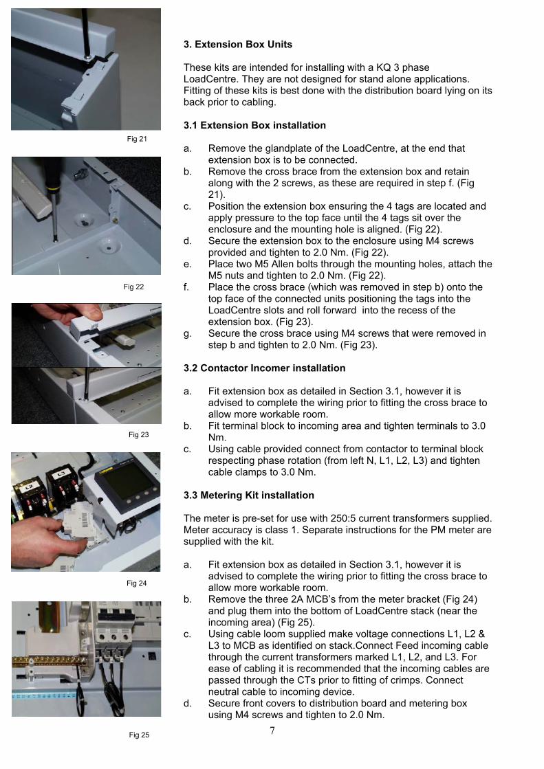
3. Extension Box Units These kits are intended for installing with a KQ 3 phase LoadCentre. They are not designed for stand alone applications. Fitting of these kits is best done with the distribution board lying on its back prior to cabling. 3.1 Extension Box installation a. Remove the glandplate of the LoadCentre, at the end that
extension box is to be connected. b. Remove the cross brace from the extension box and retain
along with the 2 screws, as these are required in step f. (Fig 21).
c. Position the extension box ensuring the 4 tags are located and apply pressure to the top face until the 4 tags sit over the enclosure and the mounting hole is aligned. (Fig 22).
d. Secure the extension box to the enclosure using M4 screws provided and tighten to 2.0 Nm. (Fig 22).
e. Place two M5 Allen bolts through the mounting holes, attach the M5 nuts and tighten to 2.0 Nm. (Fig 22).
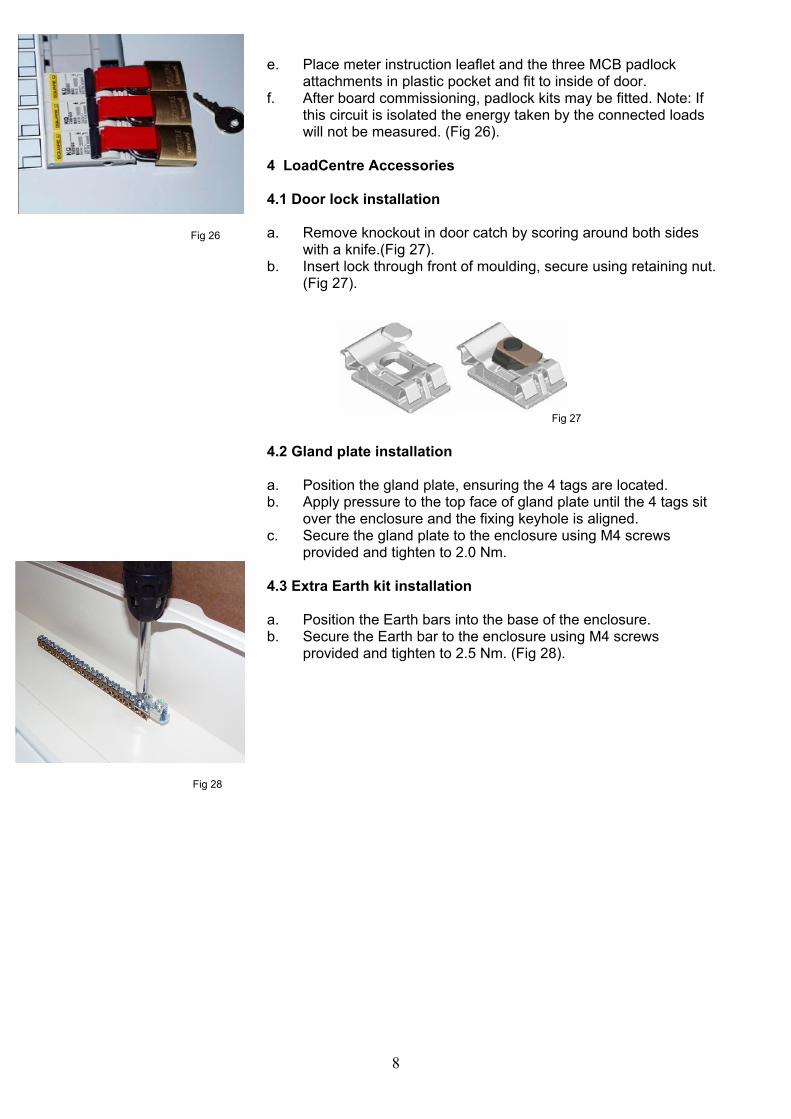
f. Place the cross brace (which was removed in step b) onto the top face of the connected units positioning the tags into the LoadCentre slots and roll forward into the recess of the extension box. (Fig 23).
g. Secure the cross brace using M4 screws that were removed in step b and tighten to 2.0 Nm. (Fig 23).
3.2 Contactor Incomer installation a. Fit extension box as detailed in Section 3.1, however it is
advised to complete the wiring prior to fitting the cross brace to allow more workable room.
b. Fit terminal block to incoming area and tighten terminals to 3.0 Nm.
c. Using cable provided connect from contactor to terminal block respecting phase rotation (from left N, L1, L2, L3) and tighten cable clamps to 3.0 Nm.
3.3 Metering Kit installation The meter is pre-set for use with 250:5 current transformers supplied. Meter accuracy is class 1. Separate instructions for the PM meter are supplied with the kit. a. Fit extension box as detailed in Section 3.1, however it is
advised to complete the wiring prior to fitting the cross brace to allow more workable room.
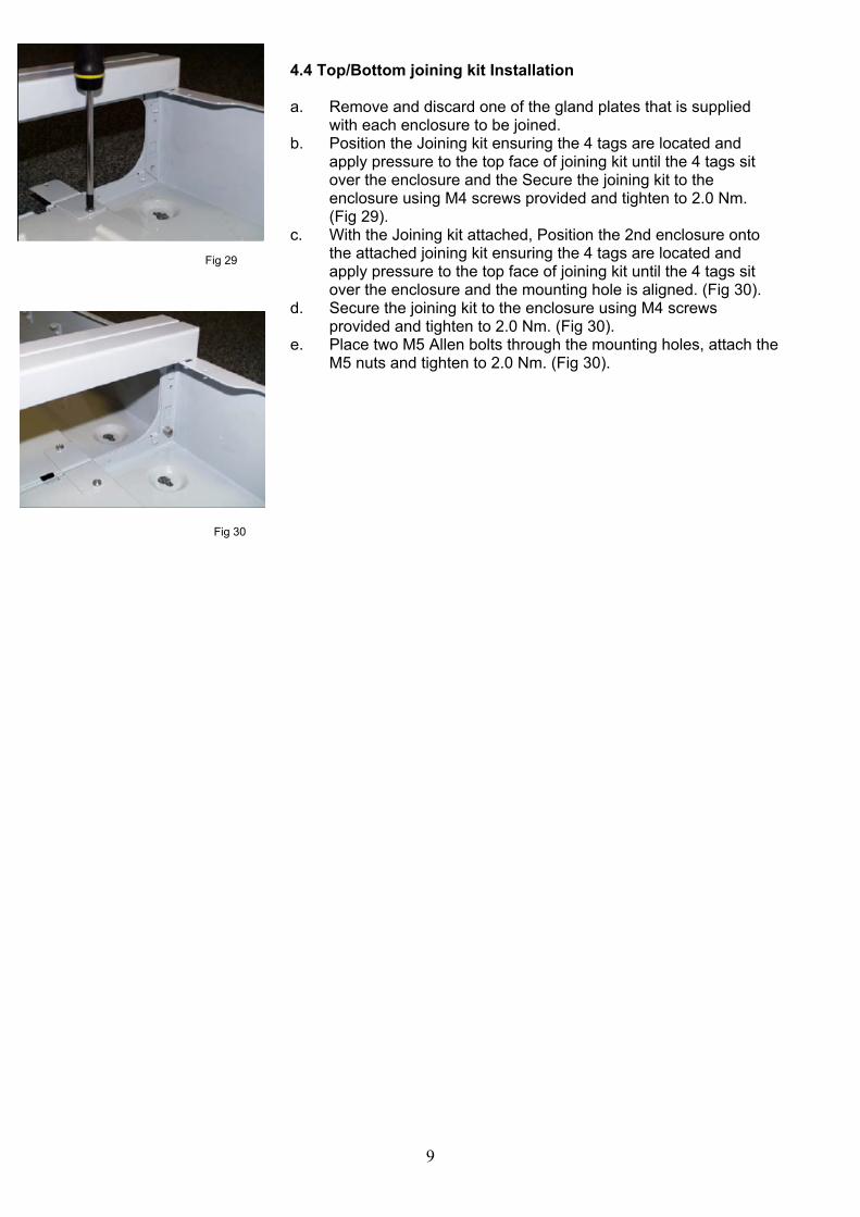
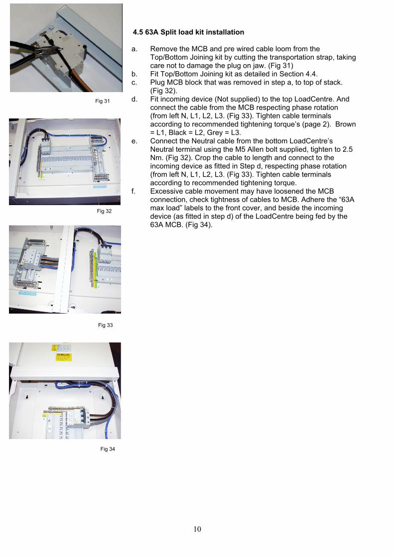
b. Remove the three 2A MCB’s from the meter bracket (Fig 24) and plug them into the bottom of LoadCentre stack (near the incoming area) (Fig 25).
c. Using cable loom supplied make voltage connections L1, L2 & L3 to MCB as identified on stack.Connect Feed incoming cable through the current transformers marked L1, L2, and L3. For ease of cabling it is recommended that the incoming cables are passed through the CTs prior to fitting of crimps. Connect neutral cable to incoming device.
d. Secure front covers to distribution board and metering box using M4 screws and tighten to 2.0 Nm.
Fig 21
Fig 22
Fig 23
Fig 24
Fig 25
8
e. Place meter instruction leaflet and the three MCB padlock attachments in plastic pocket and fit to inside of door.
f. After board commissioning, padlock kits may be fitted. Note: If this circuit is isolated the energy taken by the connected loads will not be measured. (Fig 26).
4 LoadCentre Accessories 4.1 Door lock installation a. Remove knockout in door catch by scoring around both sides
with a knife.(Fig 27). b. Insert lock through front of moulding, secure using retaining nut.
(Fig 27). 4.2 Gland plate installation a. Position the gland plate, ensuring the 4 tags are located. b. Apply pressure to the top face of gland plate until the 4 tags sit
over the enclosure and the fixing keyhole is aligned. c. Secure the gland plate to the enclosure using M4 screws
provided and tighten to 2.0 Nm. 4.3 Extra Earth kit installation a. Position the Earth bars into the base of the enclosure. b. Secure the Earth bar to the enclosure using M4 screws
provided and tighten to 2.5 Nm. (Fig 28).
Fig 27
Fig 28
Fig 26
9
4.4 Top/Bottom joining kit Installation a. Remove and discard one of the gland plates that is supplied
with each enclosure to be joined. b. Position the Joining kit ensuring the 4 tags are located and
apply pressure to the top face of joining kit until the 4 tags sit over the enclosure and the Secure the joining kit to the enclosure using M4 screws provided and tighten to 2.0 Nm. (Fig 29).
c. With the Joining kit attached, Position the 2nd enclosure onto the attached joining kit ensuring the 4 tags are located and apply pressure to the top face of joining kit until the 4 tags sit over the enclosure and the mounting hole is aligned. (Fig 30).
d. Secure the joining kit to the enclosure using M4 screws provided and tighten to 2.0 Nm. (Fig 30).
e. Place two M5 Allen bolts through the mounting holes, attach the M5 nuts and tighten to 2.0 Nm. (Fig 30).
Fig 29
Fig 30
10
4.5 63A Split load kit installation a. Remove the MCB and pre wired cable loom from the
Top/Bottom Joining kit by cutting the transportation strap, taking care not to damage the plug on jaw. (Fig 31)
b. Fit Top/Bottom Joining kit as detailed in Section 4.4. c. Plug MCB block that was removed in step a, to top of stack.
(Fig 32). d. Fit incoming device (Not supplied) to the top LoadCentre. And
connect the cable from the MCB respecting phase rotation (from left N, L1, L2, L3. (Fig 33). Tighten cable terminals according to recommended tightening torque’s (page 2). Brown = L1, Black = L2, Grey = L3.
e. Connect the Neutral cable from the bottom LoadCentre’s Neutral terminal using the M5 Allen bolt supplied, tighten to 2.5 Nm. (Fig 32). Crop the cable to length and connect to the incoming device as fitted in Step d, respecting phase rotation (from left N, L1, L2, L3. (Fig 33). Tighten cable terminals according to recommended tightening torque.
f. Excessive cable movement may have loosened the MCB connection, check tightness of cables to MCB. Adhere the “63A max load” labels to the front cover, and beside the incoming device (as fitted in step d) of the LoadCentre being fed by the 63A MCB. (Fig 34).
Fig 31
Fig 32
Fig 33
Fig 34
11
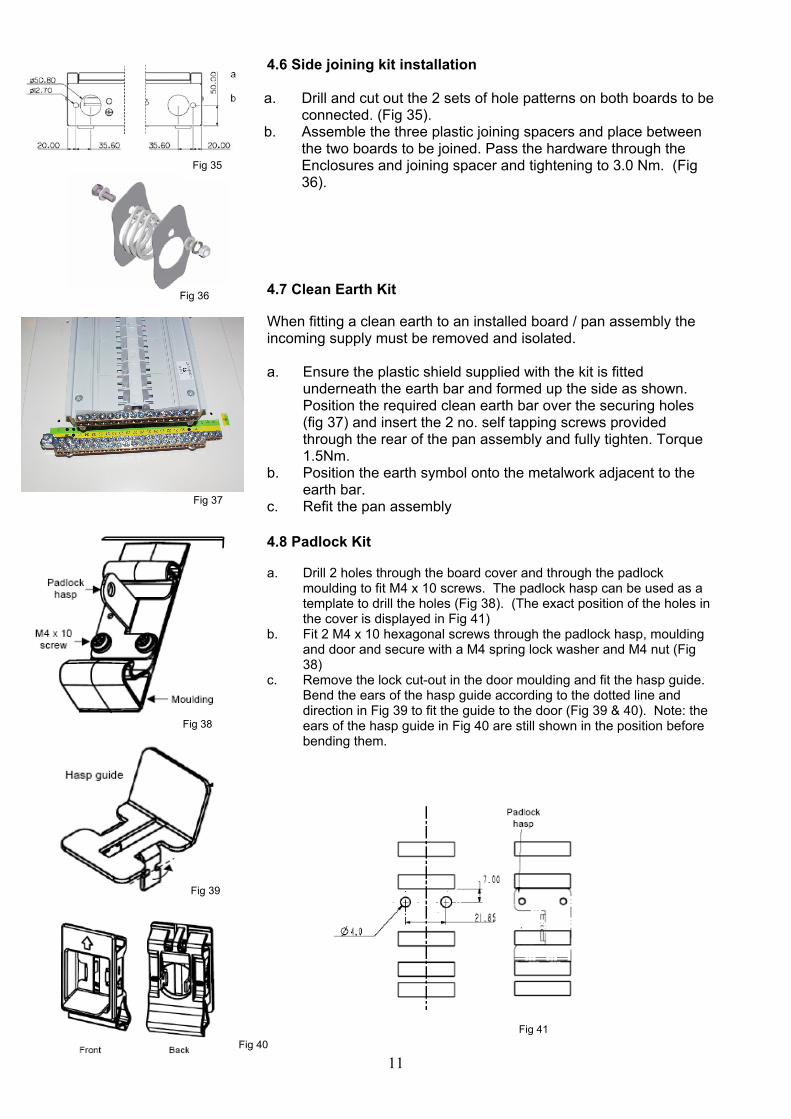
4.6 Side joining kit installation a. Drill and cut out the 2 sets of hole patterns on both boards to be
connected. (Fig 35). b. Assemble the three plastic joining spacers and place between
the two boards to be joined. Pass the hardware through the Enclosures and joining spacer and tightening to 3.0 Nm. (Fig 36).
4.7 Clean Earth Kit When fitting a clean earth to an installed board / pan assembly the incoming supply must be removed and isolated. a. Ensure the plastic shield supplied with the kit is fitted
underneath the earth bar and formed up the side as shown. Position the required clean earth bar over the securing holes (fig 37) and insert the 2 no. self tapping screws provided through the rear of the pan assembly and fully tighten. Torque 1.5Nm.
b. Position the earth symbol onto the metalwork adjacent to the earth bar.
c. Refit the pan assembly 4.8 Padlock Kit a. Drill 2 holes through the board cover and through the padlock
moulding to fit M4 x 10 screws. The padlock hasp can be used as a template to drill the holes (Fig 38). (The exact position of the holes in the cover is displayed in Fig 41)
b. Fit 2 M4 x 10 hexagonal screws through the padlock hasp, moulding and door and secure with a M4 spring lock washer and M4 nut (Fig 38)
c. Remove the lock cut-out in the door moulding and fit the hasp guide. Bend the ears of the hasp guide according to the dotted line and direction in Fig 39 to fit the guide to the door (Fig 39 & 40). Note: the ears of the hasp guide in Fig 40 are still shown in the position before bending them.
Fig 35
Fig 36
Fig 38
Fig 39
Fig 40 Fig 41
Fig 37
12
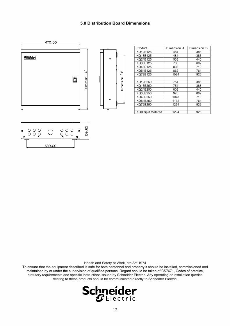
5.0 Distribution Board Dimensions
Health and Safety at Work, etc Act 1974 To ensure that the equipment described is safe for both personnel and property it should be installed, commissioned and
maintained by or under the supervision of qualified persons. Regard should be taken of BS7671, Codes of practice, statutory requirements and specific Instructions issued by Schneider Electric. Any operating or installation queries
relating to these products should be communicated directly to Schneider Electric.
Product Dimension ‘A’ Dimension ‘B’ KQ12B125 484 386 KQ18B125 484 386 KQ24B125 538 440 KQ36B125 700 602 KQ48B125 808 710 KQ54B125 862 764 KQ72B125 1024 926 KQ12B250 754 386 KQ18B250 754 386 KQ24B250 808 440 KQ36B250 970 602 KQ48B250 1078 710 KQ54B250 1132 764 KQ72B250 1294 926 KQB Split Metered 1294 926