Embed Size (px)
Citation preview

Hybrid Recorder
SR100
(Pen Type)
Instruction Manual General
Thank you for purchasing the SR series Hybrid Recorder. This manual contains information for ensuring the correct use of the SR series Hybrid Recorder. It also provides necessary information for installation, maintenance, and troubleshooting. This manual should be read by those who design and maintain equipment that uses the SR series Hybrid Recorder. Be sure to keep this manual nearby for handy reference.
No.CP-UM-5748E


1. Introduction .................................................................................................................... 1
2. For Safe Use ................................................................................................................... 4 2-1. Preconditions for Use ......................................................................................................................................... 4 2-2. Symbol Mark ...................................................................................................................................................... 4 2-3. Label .................................................................................................................................................................. 4 2-4. Important Explanation ........................................................................................................................................ 5
3. Model Code List ............................................................................................................. 6
4. Mounting and Wiring ..................................................................................................... 7 4-1. External Dimensions .......................................................................................................................................... 7 4-2. Mounting ............................................................................................................................................................ 7 4-3. Wiring ................................................................................................................................................................. 9
5. Part Names ................................................................................................................... 26 5-1. Front Section of Internal Unit ............................................................................................................................ 26 5-2. Operation/Set Keys .......................................................................................................................................... 27
6. Operation ...................................................................................................................... 28 6-1. Preparation for Operation ................................................................................................................................. 28 6-2. Basic Operation ................................................................................................................................................ 31 6-3. Operation ......................................................................................................................................................... 35
7. Factory Default Settings .............................................................................................. 38 7-1. List of Factory Default Settings......................................................................................................................... 38
8. Setting Method ............................................................................................................. 39 8-1. Basic Rules ...................................................................................................................................................... 39 8-2. Input Type Settings “Range” ............................................................................................................................. 41 8-3. Alarm Settings “Alarm” ..................................................................................................................................... 45 8-4. Calculation Settings “Calc” ............................................................................................................................... 52 8-5. Formula Settings “Formula” .............................................................................................................................. 56 8-6. Broken Line Approximation Table Settings “Seg.Tbl” ....................................................................................... 63 8-7. Chart Speed Settings “Chart” ........................................................................................................................... 64 8-8. Time axis synchronization “POC” ..................................................................................................................... 65 8-9. Subtract Printing Settings “Sub Prt” .................................................................................................................. 67 8-10. Periodic (Data Interval) Data Printing Settings “DataInt” .................................................................................. 69 8-11. Periodic (Specified Time) Data Printing Settings “PrtTime” .............................................................................. 70 8-12. List Printing Settings “ListPrt” ........................................................................................................................... 71 8-13. Message Printing 1 Settings “MsgPrt1” ............................................................................................................ 72 8-14. Message Printing 2 Settings “MsgPrt2” ............................................................................................................ 73 8-15. Recording Format Settings “PrtForm” .............................................................................................................. 74 8-16. Auto Range Settings “A.Range” ....................................................................................................................... 75 8-17. Compressed/Expanded Printing Settings “Cmp&Exp” ..................................................................................... 77 8-18. Zone Printing Settings “ZonePrt” ...................................................................................................................... 79 8-19. SD Card “SD CARD” ........................................................................................................................................ 81 8-20. USB Engineering Port Settings “USB” .............................................................................................................. 87 8-21. Calendar Timer Settings “Timer” ...................................................................................................................... 88 8-22. Fail Output Settings “FailOut” ........................................................................................................................... 89 8-23. Display Settings “Display” ................................................................................................................................ 91 8-24. Measured Value Display Order Settings “D.Order” ........................................................................................... 92 8-25. Date and Time Settings “Date” ......................................................................................................................... 93 8-26. System Settings “System” ................................................................................................................................ 94 8-27. System Information Display “SysInfo” .............................................................................................................. 96
Table of contents

9. Adjustment ................................................................................................................... 97 9-1. Trace Printing Position Adjustment “Rec Adj” ................................................................................................... 97 9-2. Recording Posotion (time) Adjustment ............................................................................................................. 99 9-3. Input Adjustment “Inp Adj” .............................................................................................................................. 100 9-4. Input Shift Adjustment .................................................................................................................................... 101 9-5. Wiring and Environment for Input Adjustment ................................................................................................ 102
10. Engineering Port (Mini-USB Terminal) ................................................................... 103
11. Troubleshooting....................................................................................................... 104 11-1. Problems and Remedies ................................................................................................................................ 104 11-2. Abnormal Measured Value ............................................................................................................................. 105
12. Inspection and Maintenance ................................................................................... 106 12-1. Routine Inspection .......................................................................................................................................... 106 12-2. Consumable Parts and Replacement Guideline ............................................................................................. 106 12-3. Battery removal method for the purpose of disposa ....................................................................................... 107
13. Option ....................................................................................................................... 109 13-1. External Operation Settings “Dig Inp” ............................................................................................................. 109 13-2. Operation Recording Settings “Ope.Rec” ....................................................................................................... 112 13-3. COM Port Settings “COM1” and “COM2” ....................................................................................................... 113 13-4. IP Address etc… Settings “Ether” ................................................................................................................... 114 13-5. SNTP Settings “SNTP” ................................................................................................................................... 115 13-6. E-mail Settings “E-mail” .................................................................................................................................. 116
14. Specifications ........................................................................................................... 119
- 1 -
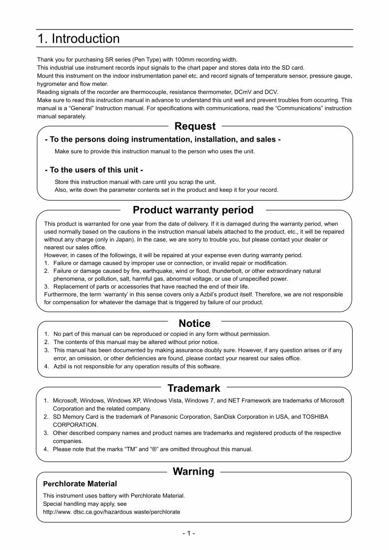
1. Introduction Thank you for purchasing SR series (Pen Type) with 100mm recording width. This industrial use instrument records input signals to the chart paper and stores data into the SD card. Mount this instrument on the indoor instrumentation panel etc. and record signals of temperature sensor, pressure gauge, hygrometer and flow meter. Reading signals of the recorder are thermocouple, resistance thermometer, DCmV and DCV. Make sure to read this instruction manual in advance to understand this unit well and prevent troubles from occurring. This manual is a “General” Instruction manual. For specifications with communications, read the “Communications” instruction manual separately.
- To the persons doing instrumentation, installation, and sales -
Make sure to provide this instruction manual to the person who uses the unit.
- To the users of this unit -
Store this instruction manual with care until you scrap the unit. Also, write down the parameter contents set in the product and keep it for your record.
Request
This product is warranted for one year from the date of delivery. If it is damaged during the warranty period, when used normally based on the cautions in the instruction manual labels attached to the product, etc., it will be repaired without any charge (only in Japan). In the case, we are sorry to trouble you, but please contact your dealer or nearest our sales office. However, in cases of the followings, it will be repaired at your expense even during warranty period. 1. Failure or damage caused by improper use or connection, or invalid repair or modification. 2. Failure or damage caused by fire, earthquake, wind or flood, thunderbolt, or other extraordinary natural
phenomena, or pollution, salt, harmful gas, abnormal voltage, or use of unspecified power. 3. Replacement of parts or accessories that have reached the end of their life. Furthermore, the term ‘warranty’ in this sense covers only a Azbil’s product itself. Therefore, we are not responsible for compensation for whatever the damage that is triggered by failure of our product.
Product warranty period
1. No part of this manual can be reproduced or copied in any form without permission. 2. The contents of this manual may be altered without prior notice. 3. This manual has been documented by making assurance doubly sure. However, if any question arises or if any
error, an omission, or other deficiencies are found, please contact your nearest our sales office. 4. Azbil is not responsible for any operation results of this software.
Notice
Perchlorate Material
This instrument uses battery with Perchlorate Material. Special handling may apply, see http://www. dtsc.ca.gov/hazardous waste/perchlorate
Warning
1. Microsoft, Windows, Windows XP, Windows Vista, Windows 7, and NET Framework are trademarks of Microsoft
Corporation and the related company. 2. SD Memory Card is the trademark of Panasonic Corporation, SanDisk Corporation in USA, and TOSHIBA
CORPORATION. 3. Other described company names and product names are trademarks and registered products of the respective
companies. 4. Please note that the marks “TM” and “®” are omitted throughout this manual.
Trademark

- 2 -
Before use
Make sure to check the following before use after unpacking the unit. If you have any question, please contact your dealer or our nearest office.
1. Exterior check Check that the appearance of the product has no damage.
2. Model code check Check that the model code of the purchased product is correct.
Model code label and application place
The label as follows is attached on the upper surface of the product case and the chassis.
Model code → SR- Serial number → Y5 CHINO
M A D E I N J A P A N
3. Accessories check Check the following accessories attached to the product.
Item Q'ty Remarks
Instruction manual 1 CD-R
Instruction manual [Installation/Wiring] 1 Booklet
Bracket 2 (1 set) For panel mounting, 22025-029001
Terminal screw 5 M3.5, for input terminal (spares for missing)
Chart paper 1 81406088-001
Cartridge pen (Analog pen) 1 each Red (1st pen), Green (2nd pen) Blue (3rd pen), Brown (4th pen)
Plotter pen (Digital pen) 1 Purple
In addition, if accessories are purchased additionally, those products may be attached.
1. Do not drop the product while take it out of the box 2. When transporting the unit, pack in the dedicated package box, and put the box in an outer case with a bed of
cushion. With the consideration to the case above, it is recommended that the dedicated package box for the unit is stored.
3. When the unit is removed from the panel and not used for a long time, put it in the dedicated package box, and store it in a place with normal ambient temperature and less dust.
Request

- 3 -
4. About attached chart paper For the unit, the chart paper 81406088-001 (1 book) is available and attached. For the case that the chart paper is to be specified, various scales are available as follows.
Item Item number Printed scale
(The following numbers are printed.) Remarks
Folding chart 50 divisions
81406088-001 0,20,40,60,80,100 10 books
16m
Folding chart 40 divisions
81425048-004
0,10,20,30,40 0,20,40,60,80 0,50,100,150,200 The above 3 paterns are printed.
10 books 16m
Folding chart 50 divisions
81425048-001
0,10,20,30,40,50 0,20,40,60,80,100 0,40,80,120,160,200 The above 3 paterns are printed.
10 books 16m
Folding chart 60 divisions
81425048-002
0,10,20,30,40,50,60 0,20,40,60,80,100,120 0,50,100,150,200,250,300 The above 3 paterns are printed.
10 books 16m
Folding chart 70 divisions
81425048-003 0,2,4,6,8,10,12,14 10 books
16m
Folding chart 75 divisions
81425048-005 0,50,100,150 10 books
16m
Clean paper chart 50 divisions
81407115-001 0,20,40,60,80,100 10 books
12m
* The chart paper has the same printed linear scale as the standard scale. Therefore, it can be shared in regardless of input types (thermocouple, resistance thermometer, or others).
5. Restriction of digital recording/printing function (1) When the chart speed is set to 150mm/H or more, printing function for other than time line, power-on printing,
data printing, list printing and setting change mark is disabled. (2) Printing is formed with dots of one pin. Therefore, if the power is turned off while characters are being formed,
they cannot be formed correctly. This is not abnormal.
6. Service parts For the unit, service parts are available as follows.
Item Item number Remarks
Cartridge pen (Analog pen) Red SR-931CP000R 3 pieces
Cartridge pen (Analog pen) Green SR-931CP000G 3 pieces
Cartridge pen (Analog pen) Blue SR-931CP000B 3 pieces
Cartridge pen (Analog pen) Brown SR-931CP000C 3 pieces
Plotter pen (Digital pen) Purple 81446296-001 3 pieces
SD card 512MB SR-911SD0512
1GB SR-911SD1000
2GB SR-911SD2000
250Ω resistor Accuracy ±0.02% 81401325 1 resistor
Accuracy ±0.05% 81446642-001 2 resistors
- 4 -
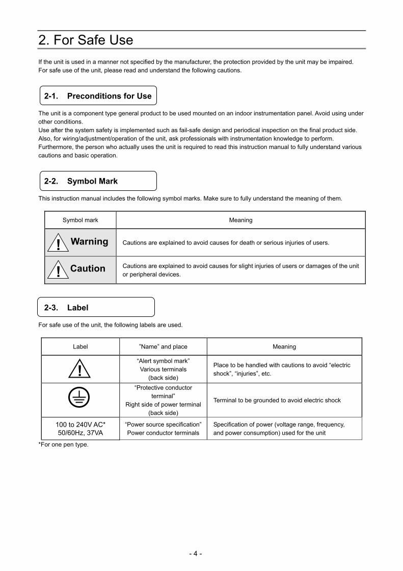
2. For Safe Use If the unit is used in a manner not specified by the manufacturer, the protection provided by the unit may be impaired. For safe use of the unit, please read and understand the following cautions.
2-1. Preconditions for Use
The unit is a component type general product to be used mounted on an indoor instrumentation panel. Avoid using under other conditions. Use after the system safety is implemented such as fail-safe design and periodical inspection on the final product side. Also, for wiring/adjustment/operation of the unit, ask professionals with instrumentation knowledge to perform. Furthermore, the person who actually uses the unit is required to read this instruction manual to fully understand various cautions and basic operation.
2-2. Symbol Mark
This instruction manual includes the following symbol marks. Make sure to fully understand the meaning of them.
Symbol mark Meaning
Cautions are explained to avoid causes for death or serious injuries of users.
Cautions are explained to avoid causes for slight injuries of users or damages of the unit or peripheral devices.
2-3. Label
For safe use of the unit, the following labels are used.
*For one pen type.
Label ”Name” and place Meaning
“Alert symbol mark” Various terminals
(back side)
Place to be handled with cautions to avoid “electric shock”, “injuries”, etc.
“Protective conductor terminal”
Right side of power terminal (back side)
Terminal to be grounded to avoid electric shock
100 to 240V AC* 50/60Hz, 37VA
“Power source specification”Power conductor terminals
Specification of power (voltage range, frequency, and power consumption) used for the unit
! Warning
! Caution
!

- 5 -
2-4. Important Explanation
To avoid severe accidents, make sure to read and understand the following.
1. Switch and overcurrent protection device This unit is not provided with a replaceable overcurrent protective device. Prepare a switch and an overcurrent protective device for the power supply (circuit breakers, circuit protectors or the like) within 3m of this unit in a location where the operator can access easily. Use a switch and an overcurrent protective device conforming to IEC60947-1 and IEC60947-3.
2. Be sure to ground this instrument To avoid electric shock, before turning the power on, connect the protective conductor terminal of this recorder to the protective conductor of the power supply equipment, and do not remove it during use.
3. Before turning on the power supply For safety, first check that the power source is within the range indicated on the power label, and then turn on the external power switch.
4. Avoid repair and modification Avoid repair and modification with parts replacement by persons other than service personnel authorized by Azbil. Not only damage or malfunction of this recorder may occur, but also dangers such as electric shock may occur. In addition, the inner unit does not have to be pulled out in the normal use.
5. Use the unit following the instruction manual For safe use, use the unit following the instruction manual. Please note that Azbil does not have any responsibilities for any claims for failures or damages occurred with abuse or misuse of this recorder.
6. Installing the safety device Regarding the use of devices that anticipates a big loss due to failure of this unit, always install a safety device for preventing these losses and implement fail safe design in the final instrumentation. Do not use this unit in important in facilities related to, human life, atomic energy, aviation and space.
7. Turn off the power supply if abnormality occurs Turn off the power supply immediately and contact your local Azbil’s sales office if any abnormal odor, noise or any smoke occurs, or if this unit becomes high temperature that is too hot to be touched.
8. Do not put hands in this product Do not put your hands or tools inside of this product. It may cause electric shock or injuries. There is no operation such as pulling out an inner unit or using tools when using this product.
Overcurrentprotection device
Switch
! Warning
To the protective conductor of power supply facility
Power/protective conductor terminal
Power source
Power terminal Protective conductor terminal
Power label
100 to 240V AC
50/60Hz 40VA MAX
For safety, the fuse below is included in the power unit of the unit. It cannot be replaced.
Manufacturer: Daito Communication Apparatus Co., Ltd Model:SBL32
Fuse in power unit Reference

- 6 -
3. Model Code List
SR-1NNN
Input point 01: 1 pen 02: 2 pen 03: 3 pen 04: 4 pen Power A: 100 to 240V AC Communications N: None E: Ethernet R: RS232C A: RS422A/RS485 Q: RS232C + RS485 C: RS422A/RS485 + RS485 G: Ethernet + RS422A/RS485 + RS485
Alarm output + remote contacts 0: None 2: 2 mechanical relay 'a' contact alarm outputs 4: 4 mechanical relay 'c' contact alarm outputs + 5 remote contacts A: 6 mechanical relay 'a' contact alarm outputs + 5 remote contacts Addition 0: None D: With inspection results Y: With traceability certification T: Tropical treatment*1 B: With inspection results + tropical treatment*1
*1 Tropical treatment does not comply with the CE marking.
- 7 -
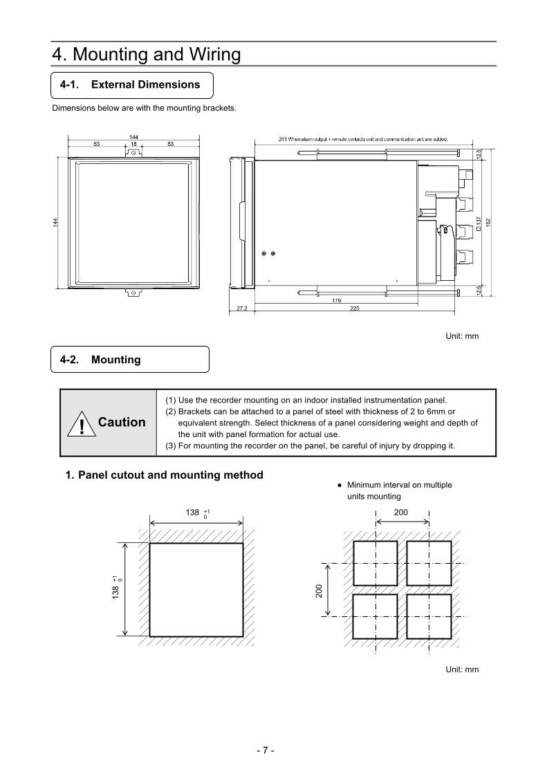
4. Mounting and Wiring
4-1. External Dimensions
Dimensions below are with the mounting brackets.
Unit: mm
4-2. Mounting
(1) Use the recorder mounting on an indoor installed instrumentation panel. (2) Brackets can be attached to a panel of steel with thickness of 2 to 6mm or
equivalent strength. Select thickness of a panel considering weight and depth of the unit with panel formation for actual use.
(3) For mounting the recorder on the panel, be careful of injury by dropping it.
1. Panel cutout and mounting method
Unit: mm
138
+1
0
+1 0
138 200
200
Minimum interval on multiple units mounting
! Caution
- 8 -
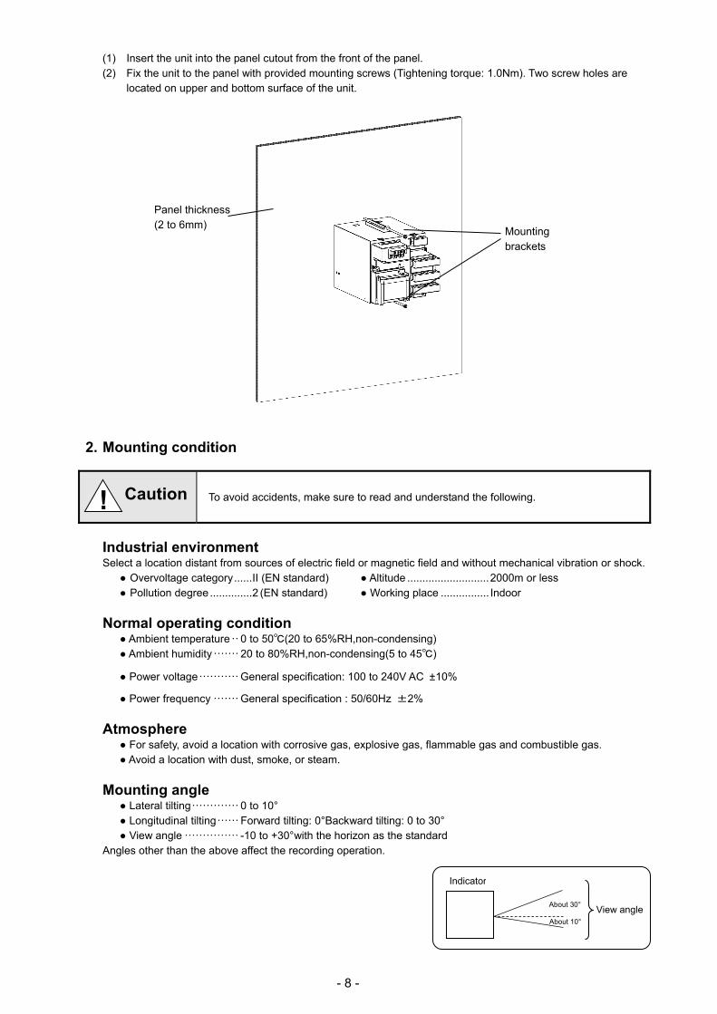
(1) Insert the unit into the panel cutout from the front of the panel. (2) Fix the unit to the panel with provided mounting screws (Tightening torque: 1.0Nm). Two screw holes are
located on upper and bottom surface of the unit.
2. Mounting condition
To avoid accidents, make sure to read and understand the following.
Industrial environment Select a location distant from sources of electric field or magnetic field and without mechanical vibration or shock.
Overvoltage category ...... II (EN standard) Altitude ........................... 2000m or less Pollution degree .............. 2 (EN standard) Working place ................ Indoor
Normal operating condition Ambient temperature ·· 0 to 50(20 to 65%RH,non-condensing) Ambient humidity ······· 20 to 80%RH,non-condensing(5 to 45)
Power voltage ··········· General specification: 100 to 240V AC ±10%
Power frequency ······· General specification : 50/60Hz ±2%
Atmosphere For safety, avoid a location with corrosive gas, explosive gas, flammable gas and combustible gas. Avoid a location with dust, smoke, or steam.
Mounting angle Lateral tilting ············· 0 to 10° Longitudinal tilting ······ Forward tilting: 0°Backward tilting: 0 to 30° View angle ··············· -10 to +30°with the horizon as the standard
Angles other than the above affect the recording operation.
! Caution
Indicator
View angle About 30°
About 10°
Panel thickness (2 to 6mm)
Mounting brackets
- 9 -
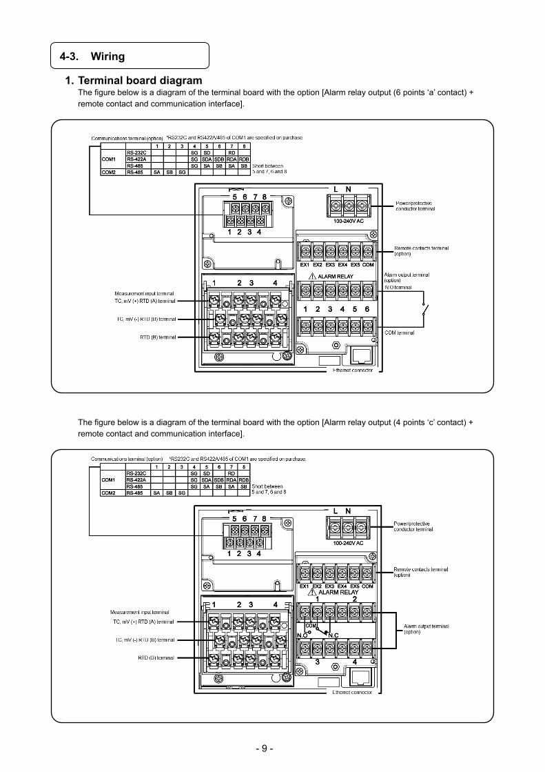
4-3. Wiring
1. Terminal board diagram The figure below is a diagram of the terminal board with the option [Alarm relay output (6 points ‘a’ contact) + remote contact and communication interface].
The figure below is a diagram of the terminal board with the option [Alarm relay output (4 points ‘c’ contact) + remote contact and communication interface].

- 10 -
The figure below is a diagram of the terminal board with the option [Alarm relay output (2 points ‘a‘ contact) and communication interface].

- 11 -
Alert symbol mark ( ) and location
Mark is attached to the location to which if human body touches, an electric shock
may be generated.
Terminal name Location of attached mark
Power terminal Lower left of power terminal
Measurement input terminal Upper left of terminal cover
Mechanical relay ‘c’ contact alarm terminal Upper left of terminal cover
Mechanical relay ‘a’ contact alarm terminal Lower left of N.O terminal
! !
! Warning
For easy wiring, the input unit, alarm output/remote contacts unit, and communication unit are removable. (1) Every unit can be removed when two mounting screws are removed. (2) The recorder and each unit are connected with a connector.
Turn off the power and then remove/attach Make sure to turn off the external power switch before units are removed/attached to prevent damages on electric circuits.
Input terminal block and alarm terminal block are removable. Reference
Only thermocouple input unit cannot be replaced with other instrument unit. If done so, measurement errors are generated.
Note Thermocouple input unit replacement
! Warning
[Alarm output/remote contacts unit][Input unit] [Communications unit]
Mounting screws
Mounting screws
Mounting screws
- 12 -
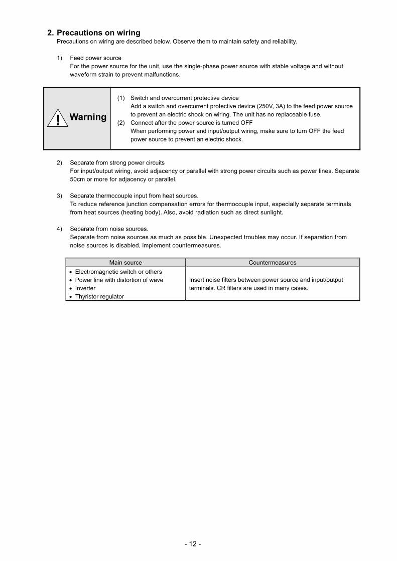
2. Precautions on wiring Precautions on wiring are described below. Observe them to maintain safety and reliability.
1) Feed power source For the power source for the unit, use the single-phase power source with stable voltage and without waveform strain to prevent malfunctions.
(1) Switch and overcurrent protective device
Add a switch and overcurrent protective device (250V, 3A) to the feed power source to prevent an electric shock on wiring. The unit has no replaceable fuse.
(2) Connect after the power source is turned OFF When performing power and input/output wiring, make sure to turn OFF the feed power source to prevent an electric shock.
2) Separate from strong power circuits For input/output wiring, avoid adjacency or parallel with strong power circuits such as power lines. Separate 50cm or more for adjacency or parallel.
3) Separate thermocouple input from heat sources. To reduce reference junction compensation errors for thermocouple input, especially separate terminals from heat sources (heating body). Also, avoid radiation such as direct sunlight.
4) Separate from noise sources. Separate from noise sources as much as possible. Unexpected troubles may occur. If separation from noise sources is disabled, implement countermeasures.
Main source Countermeasures
Electromagnetic switch or others Power line with distortion of wave Inverter Thyristor regulator
Insert noise filters between power source and input/output terminals. CR filters are used in many cases.
! Warning
- 13 -
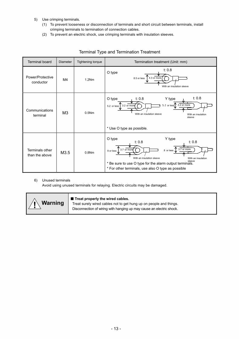
5) Use crimping terminals. (1) To prevent looseness or disconnection of terminals and short circuit between terminals, install
crimping terminals to termination of connection cables. (2) To prevent an electric shock, use crimping terminals with insulation sleeves.
Terminal Type and Termination Treatment
Terminal board Diameter Tightening torque Termination treatment (Unit: mm)
Power/Protective conductor
M4 1.2Nm
O type
Communications terminal
M3 0.5Nm
O type t: 0.8 Y type
* Use O type as possible.
Terminals other than the above
M3.5 0.8Nm
O type Y type
* Be sure to use O type for the alarm output terminals. * For other terminals, use also O type as possible
6) Unused terminals Avoid using unused terminals for relaying. Electric circuits may be damaged.
Treat properly the wired cables. Treat surely wired cables not to get hung up on people and things. Disconnection of wiring with hanging up may cause an electric shock.
8.5 or less 4.3 or more
t: 0.8
With an insulation sleeve
5.2 or less 3.2 or more
With an insulation sleeve
5.2 or less 3.2 or more
t: 0.8
With an insulation sleeve
8 or less 3.7 or more
t: 0.8
With an insulation sleeve
8 or less 3.7 or more
With an insulation sleeve
t: 0.8
! Warning

- 14 -
3. Power/protective conductor terminals wiring
1) Power/protective conductor terminals
Turn OFF feed power source. Before power/protective conductor terminals wiring, make sure to turn off the feed power source to prevent an electric shock.
2) Power terminal wiring Using 600V vinyl insulated cables as the power line, install crimping terminals with insulation sleeves to the termination for wiring. Note: Use the following standard cables. (1) IEC 60227-3 (2) ANSI/UL817 (3) CSA C22.2 No.21/49
3) Protective conductor terminal wiring Make sure to connect to the protective conductor of the power equipment. Install crimping terminals with insulation sleeves for wiring.
Grounding wire: Copper cable with wire diameter 2mm2 or more (green/yellow)
mark at power terminals After wiring the power terminals have power supply voltage applied. Make sure to install power terminal covers after wiring to prevent an electric shock.
Pay attention to power supply voltage and noise. The power supply voltage of the unit is indicated on power terminals. Applying power other than the indicated one causes accidents or malfunction. In addition, if the power has noise interference, implement countermeasures such as noise cut transformer installation.
!
! Warning
! Warning
! Caution
Display based on CSA standard in Canada. The live side of single-phase AC power supply is L, and the neutral side is N display. To get sufficient performance, observe the L/N wiring.
L/N display of power terminal Note
Power terminal
L N
Protective conductor terminal
100 - 240V AC50/60Hz 37 VA MAX
Power (voltage, frequency, and power consumption)
!
After wiring, install the terminal cover.
L N
Copper cable (green/yellow)
with 2mm2 of wire or more
Make sure to connect to
protective conductor of power
facility.
600V vinyl insulated
cable
Power source
- 15 -
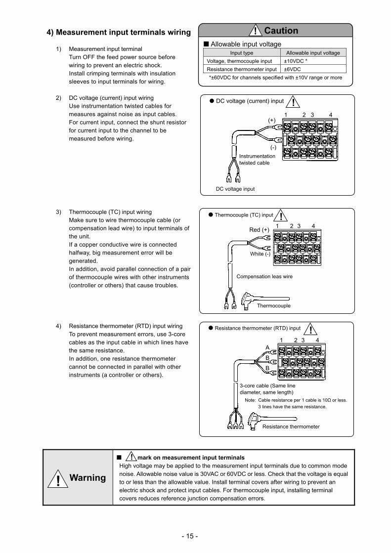
4) Measurement input terminals wiring
1) Measurement input terminal Turn OFF the feed power source before wiring to prevent an electric shock. Install crimping terminals with insulation sleeves to input terminals for wiring.
2) DC voltage (current) input wiring Use instrumentation twisted cables for measures against noise as input cables. For current input, connect the shunt resistor for current input to the channel to be measured before wiring.
3) Thermocouple (TC) input wiring Make sure to wire thermocouple cable (or compensation lead wire) to input terminals of the unit. If a copper conductive wire is connected halfway, big measurement error will be generated. In addition, avoid parallel connection of a pair of thermocouple wires with other instruments (controller or others) that cause troubles.
4) Resistance thermometer (RTD) input wiring To prevent measurement errors, use 3-core cables as the input cable in which lines have the same resistance. In addition, one resistance thermometer cannot be connected in parallel with other instruments (a controller or others).
mark on measurement input terminals High voltage may be applied to the measurement input terminals due to common mode noise. Allowable noise value is 30VAC or 60VDC or less. Check that the voltage is equal to or less than the allowable value. Install terminal covers after wiring to prevent an electric shock and protect input cables. For thermocouple input, installing terminal covers reduces reference junction compensation errors.
!
Resistance thermometer (RTD) input
3-core cable (Same line diameter, same length)
Note: Cable resistance per 1 cable is 10Ω or less.
3 lines have the same resistance.
1 2 3 4
Resistance thermometer
A
B
B
!
Allowable input voltage Input type Allowable input voltage
Voltage, thermocouple input ±10VDC *
Resistance thermometer input ±6VDC
*±60VDC for channels specified with ±10V range or more
Caution !
Compensation leas wire
Red (+)
White (-)
1 2 3 4
Thermocouple (TC) input !
Thermocouple
! Warning
Instrumentation twisted cable
DC voltage input
(+)
(-)
1 2 3 4
DC voltage (current) input !
- 16 -
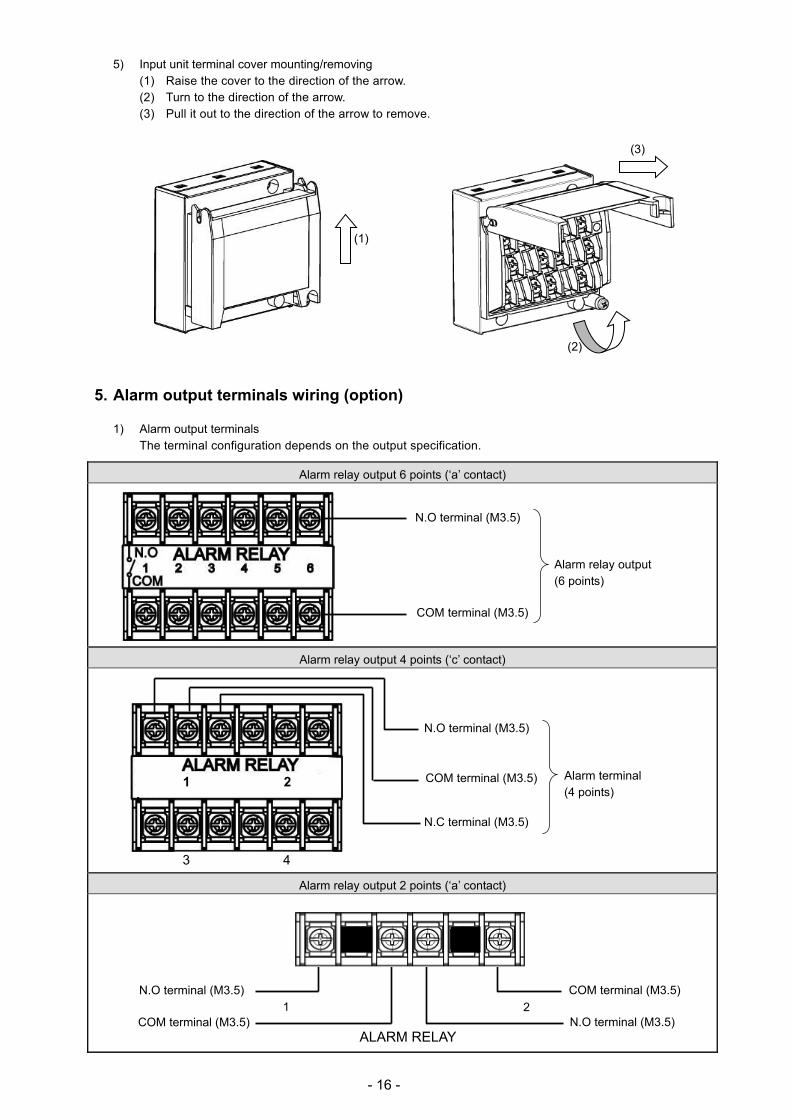
5) Input unit terminal cover mounting/removing (1) Raise the cover to the direction of the arrow. (2) Turn to the direction of the arrow. (3) Pull it out to the direction of the arrow to remove.
5. Alarm output terminals wiring (option)
1) Alarm output terminals The terminal configuration depends on the output specification.
Alarm relay output 6 points (‘a’ contact)
Alarm relay output 4 points (‘c’ contact)
Alarm relay output 2 points (‘a’ contact)
N.O terminal (M3.5)
COM terminal (M3.5)
Alarm relay output (6 points)
COM terminal (M3.5)
N.O terminal (M3.5)COM terminal (M3.5)
N.O terminal (M3.5)
ALARM RELAY
2
N.O terminal (M3.5)
COM terminal (M3.5) Alarm terminal (4 points)
1 2
3 4
N.C terminal (M3.5)
(1)
(2)
(3)
1

- 17 -
2) Wiring Turn OFF the feed power source and the power source for buffer relay before wiring to prevent an electric shock. (1) Wire the cable to the load via the buffer relay. (2) To the alarm output terminals, type O crimp style terminal with insulation sleeve which is connected to
double insulated signal wire should be connected. (Refer to 4-3. Wiring, 2. Precautions on wiring)
Mechanical relay ‘a’ contact output example Mechanical relay ‘c’ contact output example
* N.C terminal is opened on alarm occurrence in opposite way to N.O terminal.
mark on alarm output terminals Maximum of 240VAC can be connected to the alarm output terminals of this unit.
Basic insulation (dielectric strength 1390V) is carried out between the alarm output channels, however, from the malfunction etc. 240VAC may be output to each alarm output terminals. Double insulation or reinforced insulation to the outside circuit connected to an alarm output terminal should be set.
A buffer relay power supply is applied to the alarm output terminals after connections and so creates a risk of electric shock if touched. Terminal cover must be mounted after connection. Moreover, safety measures to the outside circuit should be set
Implement safety measures. The alarm output of the unit may generate output failure with wrong operation, failure, abnormal input, or others. Double insulation or reinforced insulation in outside circuit side of all the channels should be set in any system for safety ensuring.
!
: Contact protective element (Attachment to ‘a’ side is desirable.)
Buffer relay Recorder
Power
Load Z Z
N.C
N.O
COM
b a
: Contact protective element (Attachment to ‘a’ side is desirable.)
N.O
COM
b a
Z Z
Buffer relay Recorder
Power
Load
! Caution
! Warning 240VACMax
Load
240VACMax Load
*
Recorder
*Basic insulation between output channels
Double insulation or Reinforced insulation

- 18 -
3) Precautions on wiring The following are precautions on wiring.
Item Description
Mechanical relay output specification contact capacity (Common to ‘a’ contact and ‘c’ contact)
Power supply Resistance load Inductive load
100VAC 2A 1A
240VAC 2A 1A
30VDC 2A 1A
Contact protective element Z installation
Install the contact protective element which fits the buffer relay. It is effective to install the element to the coil side of the buffer relay (see the figure
of mechanical relay ‘a’ contact output example) and prevents wrong operation with light load.
Selection of buffer relay Coil rating: Contact capacity or less of output terminals Contact rating: Double of load current or more In addition, the coil surge absorption element built-in type relay is recommended. If there is no buffer relay which meets the load rating, implement another stage of buffer relay.
Selection of contact protective element
If there is no surge absorption element built-in buffer relay, install this element. The element of C/R (capacitor + resistor) is general. <C/R standard> C: 0.01μF (Rating about1kv)
R: 100 to 150Ω (Rating about 1W)
(Minimum load) 100μA100mVDC

- 19 -
6. Remote contacts terminals wiring and operation selection (option) Only with remote contacts terminals (option).
1) Remote contacts terminals
2) Wiring Turn OFF the feed power source before wiring to prevent an electric shock. (1) Use no voltage contact signals to be given to the
remote contacts terminals. (2) Install crimping terminals with insulation sleeves
to remote contacts terminals for wiring.
No voltage contact For contacts connected to the remote contacts terminals, use switches or relays driven with voltage level 30VAC or 60VDC or less or manual contacts which support light load.
Wiring example
Voltage on contact open: About 5V Current on contact short: About10mA
NoteCharacteristics of contact input terminals
! Warning
Upper row Remote contacts terminals
Remote contact enabled operation name
(1) Recording ON/OFF and three chart speed selection (two terminals of EX1 and EX2 are used) (2) Messages (No. 01 and 02) selection and printing execution (two terminals of EX1 and EX2 are
used) (3) Messages (No. 01 to 05) selection and execution (four terminals of EX1 to EX4 are used) (4) Digital data printing (arbitrary one terminal) (5) List printing (No. 1 to 3) (arbitrary one terminal for each) (6) Integration reset (arbitrary one terminal) (7) Messages No. 01 to 20 printing execution (each arbitrary one terminal) (8) Time correction execution (arbitrary one terminal) Each function requires short-circuit for one second or more between COM terminal and each terminal.
Operation allocation
Setting of allocation of operations to each terminal (EX1 to EX10) is required. Name of operations which require setting
(1) Recording ON/OFF and three chart speed selection (See 8-7. Chart Speed Setting.) (2) Message selection and printing execution (See 8-13. Message Printing 1 Settings.)
Remote contact Reference

- 20 -
3) Operation for which terminal No. is decided automatically ON: Short-circuit OFF: Open Operation name Terminal contact signal
(1) 3 chart speed selection
3 chart speed setting other than the setting here is required. (See 8-7. Chart Speed Settings.)
Recording ON/OFF and 3 chart speed selection
Between COM and EX terminals EX1 EX2
Recording ON
CS1 OFF OFF CS2 ON OFF CS3 OFF ON
Recording OFF ON ON Chart recording must be ON.
(2) Message printing (No.01 and 02)
Message setting other than the setting here is required. (See 8-13. Message Printing 1 Settings.)
Message No. 01 COM and EX1
Message No. 02 COM and EX2 At the point when the trigger signals (1 second or more) are given, the selected message is printed. Message printing with key is available.
(3) Message printing (No. 01 to 05)
Message setting other than the setting here is required. (See 8-13. Message Printing 1 Settings.)
Message Between COM and EX terminals
EX1 EX2 EX3 EX4 * No.01 OFF OFF OFF For trigger
No.02 ON OFF OFF No.03 OFF ON OFF No.04 ON ON OFF No.05 OFF OFF ON
* After message No. is selected, when the trigger signals (1 second or more) are given, the selected message is printed.
Chart recording must be ON. Message printing with key is available.
4) Operation which can be allocated to arbitrary terminal No. ON: Short-circuit OFF: Open
Operation name Terminal contact signal
(4) Digital data printing
Turn ON the terminal No. specified to “Digital data printing.” Chart recording must be ON. Digital data printing with key is enabled. Even during execution, the acceptance can be repeated only once.
(5)List printing (List No.1, 2, and 3)
Turn ON the terminal No. specified to “List 1, List 2, or List 3 printing.” Chart recording must be ON. List printing with key is available. (See 8-12. List Printing Settings)
(6)Integration reset
When “Collective reset with remote contacts (EX)” is selected with “Calculation programming”, turning ON the terminal No. specified to “Integration reset” resets the integration value. (See 8-4. Calculation Settings.)
(7)Message printing (No.01 to No.20)
Message setting other than the setting here is required. (See 8-13. Message Printing 1 Settings.) Turn ON the terminal No. specified to “Message printing (No. 01 to 20).” Chart recording must be ON. Message printing with key is available.
(8)Time correction When the current time (second) is within 0 to 30 seconds, the time is corrected to zero second by dropping the seconds. When it is within 31 to 59 seconds, the time is put forward one minute by rounding up and corrected to zero second.
1 sec.or more
For trigger
1 sec.or more
1 sec.or more

- 21 -
7. Communication I/F terminal wiring (partly option) SR100 can be connected for communications with RS232C, RS422A, RS485, and Ethernet.
1) Communication terminal type
1 2 3 4 5 6 7 8
COM1
RS232C * SG SD RD
RS422A * SG SDA SDB RDA RDB
RS485 * SG SA SB Short with
SA Short with
SB
COM2 RS485 SA SB SG
* RS232C and RS422A/485 of COM1 are to be specified on purchase.
2) Communications cables Please prepare communication cables before wiring in advance. Since exclusive cables are available from us, place an order.
(1) RS232C
Connection between PC and the unit or a line converter
Cable 9-pin connector ↔ Crimp type ring terminals RS232C cable
Shape
Internal wiring
RDSDSG
PC side 9-pin connector
Cable for RS232C (Max.15m)
RDSDSG
1
2
3
4
5
6
7
8
9
Ethernet connector
Communication terminal

- 22 -
(2) RS422A Connection between a line converter and the unit
Cable Crimp type ring terminals ↔ Crimp type ring terminals RS422A cable
(for a line converter)
Shape
4-core cable of twisted 2-core cables of twisted VCTF lines. Each side has a SG (signal ground) line. Since the line converter has no SG terminal, cut and use the cable.
Internal wiring
Connection between the unit and other devices
Cable Crimp type ring terminals ↔ Crimp type ring terminals RS422A cable (for parallel)
Shape
4-core cable of twisted 2-core cables of twisted VCTF lines. Each side has a SG (signal ground) line.
Internal wiring
Line converter side Recorder side
RDB RDA
SDA SDB
SG
SDBSDA
RDARDBSG
Device side Recorder side
SDB SDA
RDA RDB
SG
SDBSDA
RDARDBSG
(black)
(white)
(red) (green) (blue)
RDA RDB SDA SDB SG
SDASDBRDARDBSG
(black)
(white)
(red) (green)(blue)
(black)
(white)
(red) (green) (blue)
SDA SDB RDA RDB SG
SDASDBRDARDBSG
(black)
(white)
(red) (green)(blue)

- 23 -
(3) RS485 Connection between the unit and other devices and between a line converter and the unit
Cable Crimp type ring terminals ↔ Crimp type ring terminals RS485 cable
Shape
2-core cable of twisted CVVS lines. Each side has a SG (signal ground) line. Since the line converter has no SG terminal, cut and use the cable.
Internal wiring
(4) Ethernet Connection between PC and devices
For direct (one-to-one) connection, use crossover twist-pair cables with shield (available locally as STP cable).
Connection between HUB and devices (multiple devices can be connected)
For (one-to-N) connection between PC and devices via HUB, use straight twist-pair cables with shield (available locally as STP cable).
3) Communications line wiring
(1) RS232C wiring PC and devices are connected one-to-one with RS232C.
Example of terminal connection
RDA(black)
RDB(white) SG(green)
(black)SA (white)SB (green)SG
Device side, Line converter side Recorder side
RDA RDB
SG
SASBSG
SD RD
SG Cable for RS232C (Max.15m)
Device side
RD SD SG
RZ-CRS6 Communications port
PC side
- 24 -
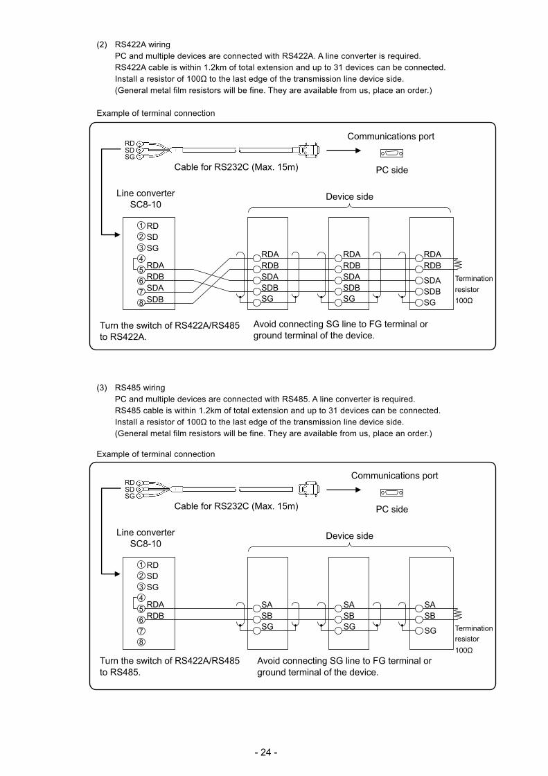
(2) RS422A wiring PC and multiple devices are connected with RS422A. A line converter is required. RS422A cable is within 1.2km of total extension and up to 31 devices can be connected. Install a resistor of 100Ω to the last edge of the transmission line device side. (General metal film resistors will be fine. They are available from us, place an order.)
Example of terminal connection
(3) RS485 wiring PC and multiple devices are connected with RS485. A line converter is required. RS485 cable is within 1.2km of total extension and up to 31 devices can be connected. Install a resistor of 100Ω to the last edge of the transmission line device side. (General metal film resistors will be fine. They are available from us, place an order.)
Example of terminal connection
Turn the switch of RS422A/RS485to RS422A.
SASBSG
RDBRDA
SD RD
SG
1
2
3
4
5
6
7
8
SASBSG
SA SB
SG
Turn the switch of RS422A/RS485 to RS485.
Avoid connecting SG line to FG terminal or ground terminal of the device.
Termination
resistor
100Ω
Device sideLine converter SC8-10
Cable for RS232C (Max. 15m)
RZ-CRS6 Communications port
PC side
SD RD
SG
Avoid connecting SG line to FG terminal or ground terminal of the device.
RDBRDA
SDASDBSG
Termination
resistor
100Ω
Device sideLine converter SC8-10
RDBRDA
SDASDB
SD RD
SG
1
2
3
4
5
6
7
8
Cable for RS232C (Max. 15m)
RZ-CRS6 Communications port
PC side
SD RD
SG
RDBRDA
SDASDBSG
RDB RDA
SDA SDB SG

- 25 -
(4) Ethernet wiring Example of connection between PC and Ethernet devices (one-to-one connection)
Example of connection between PC and HUB/Ethernet devices (one-to-N connection)
Crossover twist-pair cable with shield (Max.100m)
Device sidePC side
Device sideHUB
Straight twist-pair cable with shield (Max.100m)
PC side
HUB
Straight twist-pair cable with shield (Max.100m)
Straight twist-pair cable with shield (Max.100m)

- 26 -
5. Part Names
5-1. Front Section of Internal Unit
The front of the door is made of glass. Avoid giving any shock to the glass or giving any strong force to the frame
for preventing any injury due to breakage.
How to handle the door Note 1
Avoid closing the door in the state of operation/set keys opened. If the door is closed in the state of the
operation/set keys opened, the mechanism of the operation/set keys allows the operation/set keys to be lifted to
the direction for closing to prevent damage; however, behavior for protection is not guaranteed. If the door is
closed forcedly or fast, it may be damaged.
Operation/set key Note 2
Power switch Open the display board same direction as the unit door. The power switch is located at the upper left of the unit.
Enlarged view of power switch
SD card slot
Operation/set keys Engineering port USB communication connector
Display
- 27 -
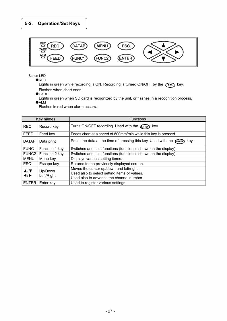
5-2. Operation/Set Keys
Status LED
REC Lights in green while recording is ON. Recording is turned ON/OFF by the key.
Flashes when chart ends. CARD
Lights in green when SD card is recognized by the unit, or flashes in a recognition process. ALM
Flashes in red when alarm occurs.
Key names Functions
REC Record key Turns ON/OFF recording. Used with the key.
FEED Feed key Feeds chart at a speed of 600mm/min while this key is pressed.
DATAP Data print Prints the data at the time of pressing this key. Used with the key.
FUNC1 Function 1 key Switches and sets functions (function is shown on the display). FUNC2 Function 2 key Switches and sets functions (function is shown on the display). MENU Menu key Displays various setting items. ESC Escape key Returns to the previously displayed screen.
/ /
Up/Down Left/Right
Moves the cursor up/down and left/right. Used also to select setting items or values. Used also to advance the channel number.
ENTER Enter key Used to register various settings.

- 28 -
6. Operation
6-1. Preparation for Operation
1. How to set chart paper
1. Pulling out the chart cassette
(1) Open the unit door. (2) Hold the chart cassette grip and pull it toward
you. (3) Each pen rises up when pulled out the chart
cassette. 2. Setting chart paper
(1) Open the chart guide and chart feeding holder. (2) Loosen the both ends of chart to prevent double
feed.
(3) Set chart in the chart housing at the back of the
chart cassette. The “square” hole and “rectangle” hole should be at the left and right side of the chart respectively. Make sure to set chart in the correct direction.
(4) Draw out chart approximately 20cm and set
holes on the both ends to the sprockets of the chart drum. Put two or three folds of chart in the chart tray at the front of the chart cassette and then close the chart guide and chart feeding holder opened in the step (1).
(5) Turn the thumb wheel downward and make sure
that the holes on the both ends of chart are not released from the sprockets, and feeding is smoothly done.
3. Returning the chart cassette to the inside of
the unit (1) Align the guide of the chart cassette with the
guide rail located at the both sides of the internal chassis and then insert the cassette until it is locked.
(2) Operate the key to check if the chart is fed properly and smoothly. If not, reset the chart again.
Chart feeding holder
Chart guide
Chart cassette grip
Operation/set key part
Thumb wheel
Be careful of injury by dropping the chart cassette after pulling it from inner unit. Take care not to catch your fingers in the unit when putting the chart cassette back.
Handling of chart cassette Note
- 29 -
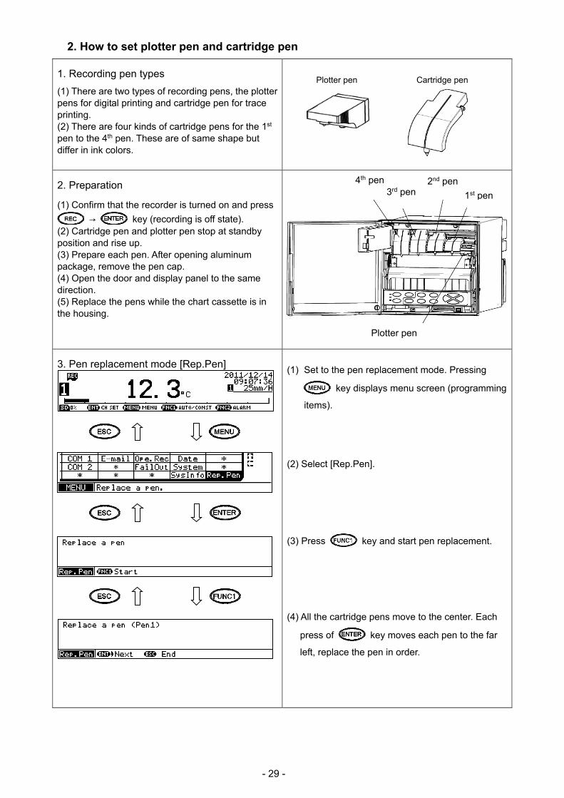
2. How to set plotter pen and cartridge pen
1. Recording pen types
(1) There are two types of recording pens, the plotter pens for digital printing and cartridge pen for trace printing. (2) There are four kinds of cartridge pens for the 1st pen to the 4th pen. These are of same shape but differ in ink colors.
2. Preparation
(1) Confirm that the recorder is turned on and press
→ key (recording is off state). (2) Cartridge pen and plotter pen stop at standby position and rise up. (3) Prepare each pen. After opening aluminum package, remove the pen cap. (4) Open the door and display panel to the same direction. (5) Replace the pens while the chart cassette is in the housing.
3. Pen replacement mode [Rep.Pen]
(1) Set to the pen replacement mode. Pressing
key displays menu screen (programming
items). (2) Select [Rep.Pen].
(3) Press key and start pen replacement.
(4) All the cartridge pens move to the center. Each
press of key moves each pen to the far
left, replace the pen in order.
Cartridge pen Plotter pen
4th pen 2nd pen 3rd pen 1st pen
Plotter pen

- 30 -
4. Setting plotter pen (1) Insert the plotter pen into the penholder untill it stops. (Note) Incomplete insertion may result in recording troubles. (2) For removing of the plotter pen, pull it from the penholder.
5. Setting cartridge pen (1) From an angle shown in the figure, push lug 1 of the cartridge pen into cavity 3 of the penholder. Next, rotate the cartridge pen to the direction of the arrow then push lug 2 into cavity 4. (2) For removing, rotate the cartridge pen to the direction of the arrow as shown in the figure above and remove lug 3 of the cartridge pen from cavity 1 of the penholder then remove lug 4 of the cartridge pen from cavity 2 of the penholder.
3. How to set power frequency
Set the power frequency of the utilized region, setting so does not relate to operation of the unit directory, but this will result in the reduction of the power supply noise. Default setting is 50Hz, switch the power frequency in the region of 60Hz. Refer to “8-26. System Settings” for power frequency settings.
Insert the plotter pen until it makes clicking sound. When the insertion is done correctly, “A” part fits into the penholder.
1. Pen tip The pen tip is made of felt material. If an excessive force is added to it, the top of the pen tip will be crushed and making clear printing or tracing becomes impossible. 2. Pen cap Each pen is provided with a pen cap for preventing drying and protecting the pen tip. Remove and retain the pen caps before setting the pen. For stopping the recording more than a day, remove the pen then put the cap on and store it.
Maintenance of pens
Incorrect insertion Correct insertion
Setting plotter pen Ref 1
Main Shaft
Penholder
Plotter pen
Note 2
Determine the pen number by the color of the cartridge pen. Red: 1st pen Green: 2nd pen Blue: 3rd pen Brown: 4th pen
Colors of the cartridge pen Ref 2
Index of the color
When loading or replacing the cartridge pen, make sure to turn the power off, be in the state of REC OFF or perform under the pen replacement mode. Otherwise the dotting mechanism operates during cartridge pen replacement and unexpected force is applied to the mechanical parts then the instrument may be damaged. Do not move the recording structure right/left by force.
Attachment/removal of cartridge penNote 1
- 31 -
6-2. Basic Operation
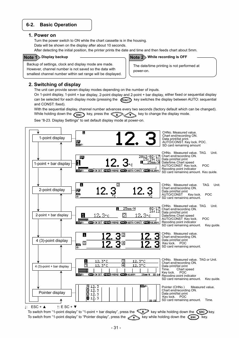
1. Power on Turn the power switch to ON while the chart cassette is in the housing. Data will be shown on the display after about 10 seconds. After detecting the initial position, the printer prints the date and time and then feeds chart about 5mm.
2. Switching of display The unit can provide seven display modes depending on the number of inputs. On 1-point display, 1-point + bar display, 2-point display and 2-point + bar display, either fixed or sequential display can be selected for each display mode (pressing the key switches the display between AUTO: sequential and CONST: fixed). With the sequential display, channel number advances every two seconds (factory default which can be changed). While holding down the key, press the / key to change the display mode.
See “8-23. Display Settings” to set default display mode at power-on.
CHNo. Measured value. Chart end/recording ON. Data print/list print. AUTO/CONST. Key lock. POC. SD card remaining amount
CHNo. Measured value. TAG. Unit.Chart end/recording ON. Data print/list print AUTO/CONST Key lock. POCSD card remaining amount. CHNo. Measured value. TAG. Unit.Chart end/recording ON. Data print/list print Date/time. Chart speed AUTO/CONST Key lock. POCRecoding point indicator SD card remaining amount. Key guide. CHNo. Measured value. Chart end/recording ON. Data print/list print Key lock. POC SD card remaining amount.
CHNo. Measured value. TAG or Unit.Chart end/recording ON. Data print/list print Time. Chart speed Key lock. POC Recoding point indicator SD card remaining amount. Key guide.
Pointer (CHNo.) Measured value.Chart end/recording ON. Data print/list print Key lock. POC SD card remaining amount. Time.
↓: ESC + ↑: E SC +
To switch from “1-point display” to “1-point + bar display”, press the key while holding down the key. To switch from “1-point display” to “Pointer display”, press the key while holding down the key.
CHNo. Measured value. TAG. Unit.Chart end/recording ON. Data print/list print Date/time. Chart speed AUTO/CONST Key lock. POCRecoding point indicator SD card remaining amount. Key guide.
1-point + bar display
2-point display
2-point + bar display
4 (3)-point display
1-point display
4 (3)-point + bar display
Pointer display
The date/time printing is not performed at power-on.
Note 2 While recording is OFF Backup of settings, clock and display mode are made. However, channel number is not saved so the data with smallest channel number within set range will be displayed.
Display backup Note 1
- 32 -
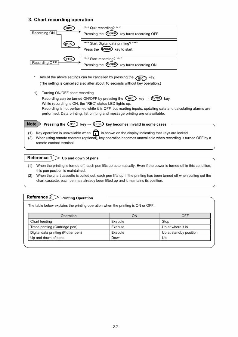
3. Chart recording operation
Recording ON
Recording OFF
* Any of the above settings can be cancelled by pressing the key.
(The setting is cancelled also after about 10 seconds without key operation.)
1) Turning ON/OFF chart recording
Recording can be turned ON/OFF by pressing the key → key. While recording is ON, the “REC” status LED lights up. Recording is not performed while it is OFF, but reading inputs, updating data and calculating alarms are performed. Data printing, list printing and message printing are unavailable.
(1) When the printing is turned off, each pen lifts up automatically. Even if the power is turned off in this condition,
this pen position is maintained. (2) When the chart cassette is pulled out, each pen lifts up. If the printing has been turned off when pulling out the
chart cassette, each pen has already been lifted up and it maintains its position.
“*** Quit recording? ***”
Pressing the key turns recording OFF.
“*** Start Digital data printing? ***”
Press the key to start.
“*** Start recording? ***”
Pressing the key turns recording ON.
(1) Key operation is unavailable when is shown on the display indicating that keys are locked. (2) When using remote contacts (optional), key operation becomes unavailable when recording is turned OFF by a
remote contact terminal.
Pressing the key → key becomes invalid in some cases Note
Up and down of pens Reference 1
The table below explains the printing operation when the printing is ON or OFF.
Operation ON OFF
Chart feeding Execute Stop
Trace printing (Cartridge pen) Execute Up at where it is
Digital data printing (Plotter pen) Execute Up at standby position
Up and down of pens Down Up
Reference 2 Printing Operation
- 33 -
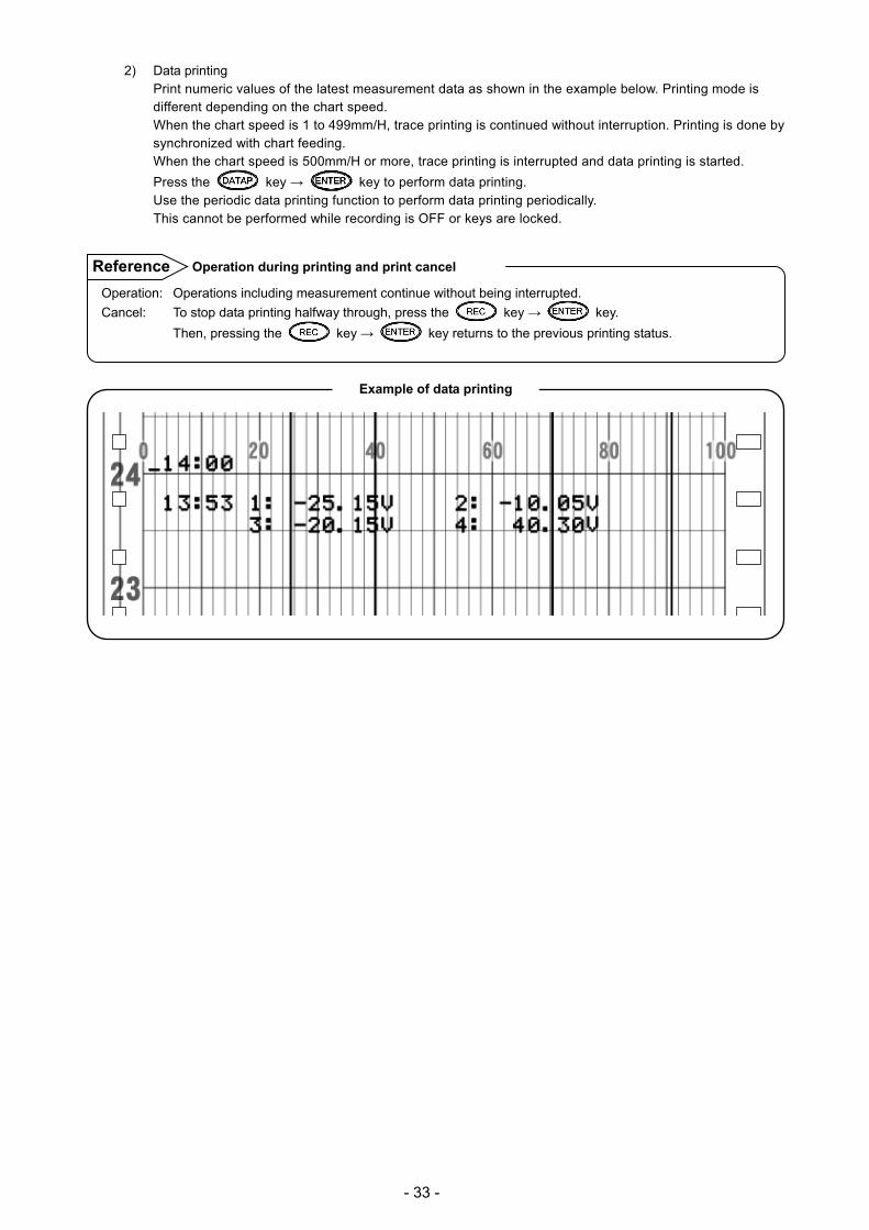
2) Data printing Print numeric values of the latest measurement data as shown in the example below. Printing mode is different depending on the chart speed. When the chart speed is 1 to 499mm/H, trace printing is continued without interruption. Printing is done by synchronized with chart feeding. When the chart speed is 500mm/H or more, trace printing is interrupted and data printing is started.
Press the key → key to perform data printing. Use the periodic data printing function to perform data printing periodically. This cannot be performed while recording is OFF or keys are locked.
Operation: Operations including measurement continue without being interrupted.
Cancel: To stop data printing halfway through, press the key → key.
Then, pressing the key → key returns to the previous printing status.
Operation during printing and print cancel Reference
Example of data printing
- 34 -
3) Chart feed Chart can be fed using the key.
While the key is pressed, chart is fed at a speed of 600mm/min. When fast-feeding chart, recording is stopped. Feed chart when a measurement target or measurement condition is changed.
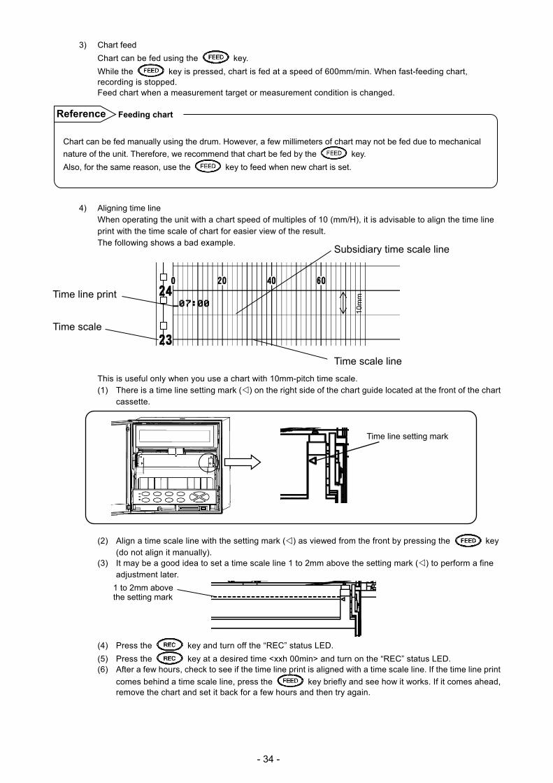
4) Aligning time line When operating the unit with a chart speed of multiples of 10 (mm/H), it is advisable to align the time line print with the time scale of chart for easier view of the result. The following shows a bad example.
Time line print
Time scale
This is useful only when you use a chart with 10mm-pitch time scale. (1) There is a time line setting mark () on the right side of the chart guide located at the front of the chart
cassette.
Time line setting mark
(2) Align a time scale line with the setting mark () as viewed from the front by pressing the key (do not align it manually).
(3) It may be a good idea to set a time scale line 1 to 2mm above the setting mark () to perform a fine adjustment later.
(4) Press the key and turn off the “REC” status LED.
(5) Press the key at a desired time <xxh 00min> and turn on the “REC” status LED. (6) After a few hours, check to see if the time line print is aligned with a time scale line. If the time line print
comes behind a time scale line, press the key briefly and see how it works. If it comes ahead, remove the chart and set it back for a few hours and then try again.
Chart can be fed manually using the drum. However, a few millimeters of chart may not be fed due to mechanical
nature of the unit. Therefore, we recommend that chart be fed by the key.
Also, for the same reason, use the key to feed when new chart is set.
Feeding chart Reference
Subsidiary time scale line
10m
m
Time scale line
1 to 2mm above the setting mark

- 35 -
6-3. Operation
1. Types and contents of chart recording There are two types of chart recording: trace printing and digital recording/printing. Without setting particular items, trace printing and fixed time printing are performed while recording is ON.
Item Contents
Cha
rt r
ecor
ding
Trace printing (Cartridge pen) Trend printing is executed for each pen (channel).
1st pen 2nd pen 3rd pen 4th pen
Red Green Blue Brown
Dig
ital r
ecor
ding
/prin
ting
(Plo
tter
pen)
Alarm printing Prints time or alarm point when alarm is generated/cleared. Periodic data printing Adds digital record/print on a trace print in desired intervals. Data printing Performs digital recording/printing when required. List printing Prints a list of all or specified parameters when required. Fixed time printing Prints date (year/month/date), time/time line (linked to the chart
speed and printed), chart speed, max/min chart record, channel number and tag and unit.
Message printing Prints a message which can contain up to 40 characters. Calendar timer printing Prints when both calendar timer is ON/OFF and printing are set to ON.Operation recording When using remote contacts (optional), the status of remote input
No. (ON/OFF) is printed at the specified position with a bar line. Setting change mark When setting is changed, “∆” is printed at the right side of chart. Power-on time printing Date and time are printed at power ON. Time axis sync. mark printing
(1) When the time axis synchronization (POC) is switched ON or OFF, its time, mark (*), and ON or OFF are printed.
(2) When it is ON, a mark (*) is printed to the right of the time print of fixed-time printing.
Example of trace printing and fixed time printing

- 36 -
2. Fixed time printing interval When recording is ON at the time of power-on, fixed time printing is performed first. The following table shows printing intervals which vary depending on the printing item.
Time and time line Chart speed Min/max chart record, channel number and tag and unit
Varies depending on the chart speed
At approximately 84mm intervals
At intervals of 42mm and in order of channel number.
1) Printing intervals of time and time line Time and time line are printed at the following intervals which vary by the chart speed. The start point of the intervals is 00h 00min.
Chart speed (mm/H) Time and time line Time line only Year/month/date 1 - 9 12h 00min only 6h
00h 00min only
10 - 15 4h 2h 16 - 30 2h 1h 31 - 60 1h ←
61 – 119 1h 30min 120 - 149 30min ←
150 or higher No printing 30min Example:
(1) (2) (3)
(1) Time line (2) Time
(3) POC mark (print only when time axis synchronization is ON))
2) Printing interval of max/min chart record, channels number and tag and unit
(1) These are printed at intervals of 42mm and in order of channel number. (2) Tag is not printed if not specified. (3) When you set the recording format, printing contents vary depending on the selected format. (4) Printing mode is different depending on the chart speed.
Standard (Standard), automatic range-shift (Auto Range)
Note: When Auto Range is used, the max/min chart record of the range (one of the ranges R1 to R5) used at the time of printing will be printed.
Compressed/expanded printing (Comp. & Exp.Print) Zone printing (Zone Print) + + …*
1: TIC1
0.0/200.0/400.0/500.0°C
zero/1st break point/2nd break point/span
+ + …* 1: TIC1 0.0/500.0°C
* A “+” mark is printed at the first and second break points.
* A “+” mark is printed at the edge of the printing area to indicate it.
Tag
Channel No.
Min/max chart record Unit
Trace printing 1: TIC1
0.0/500.0°C

- 37 -
3. Restrictions on recording 1) Digital recording/printing unavailable at certain chart speeds
When chart speed is set to 150mm/H or higher, printing function besides time line, power-on time printing, data printing, list printing, setting change mark are disabled.
2) Overlapping of digital recording/printing When the recording position is overlapped, printing may not be performed.
4. Operation at abnormal input 1) Out-of-range input
When an input is out of the chart printing range or measuring range, the unit indicates it by the following display or printing. Measuring range: determined by the input type
described in “8-2. Input Type Settings”.
Chart printing range: trace printing range described in “8-2. Input Type Settings”.
No. Input status Display Printing
Digital Digital Trace
(1) Input under the lower limit of
measuring range* -OVER -OVER
Downscale burnout
(2) Input under the lower limit of
chart printing range Normal display Normal print
(3) Input over the upper limit of
chart printing range Normal display Normal print
Upscale burnout
(4) Input over the upper limit of
measuring range* +OVER +OVER
* Digital display/printing is available for an input outside the measuring range if it is within ±10% of the span.
2) Disconnection of input signal Display and printing made at a disconnection of input signal depends on the “Burnout” setting.
Burnout setting Display Printing
Digital Digital Trace
None Undefined Undefined Undefined
Down BURN BURN Downscale burnout
UP BURN BURN Upscale burnout
Input status
Chart printing range
Measuring range
(1) (2) (3) (4)

- 38 -
7. Factory Default Settings
7-1. List of Factory Default Settings
Item Default value
(1) Time Current time (year/month/date: Japan time)
(2) Range
(1) Input type (2) RJ (3) Chart printing
V : -50.00 to 50.00 None -50.00 to 50.00
(3) Scale -50.00 to 50.00
(4) Unit V
(5) Tag Not set
(6) Display/printing On and OFF
(1) Display (2) Trace printing (3) Digital printing (4) SD card recording
All channels ON All channels ON All channels ON All channels ON
(7) Chart speed 20mm/H
(8) Digital recording/printing Data interval None
(9) Alarm settings Not set
(10) Subtract printing settings Not set
(11) Message settings Not set
(12) Password 3571
- 39 -
8. Setting Method
8-1. Basic Rules
The following provides general information on setting operations.
Pressing the key can return to the measured value display from any window.
1. Setting items and parameters The unit offers various condition settings to allow users to obtain various recording results and data. Major items of measuring/recording conditions, such as range, scale and chart speed, are called “setting items”, whereas detailed items of each setting item are called “setting parameters” or just “parameters”.
2. Selecting setting item Press the key on the measured value display. A list of setting items will be displayed.
Use the keys to select a setting item and press the key to confirm your selection. Some setting items may use hierarchical display.
3. Selecting setting parameter Select a setting parameter of a setting item.
A cursor is displayed at the left of each parameter. Move the cursor to a desired parameter using the
keys.
4. Key acceptance and acceptance failure
When the cursor does not move by pressing the keys or when a parameter setting
window does not open by pressing the key, it indicates that the keys have been unaccepted. Make sure to press the keys properly and try again.
5. Number of setting items and parameters Setting items vary depending on the use of option. Also, the number of setting parameters differs by setting item. The items like time and chart speed have a single parameter whereas the items like range, scale and alarm have multiple parameters requiring channel specification. Only the parameters necessary for the current setting become available for entry. Unnecessary parameters are replaced by “*” mark and the cursor does not move to them.
6. Checking setting parameters There are two ways to check setting parameters: “list printing” and “display check”, the former prints all or specified setting items and the latter calls up parameters on the display.
- 40 -
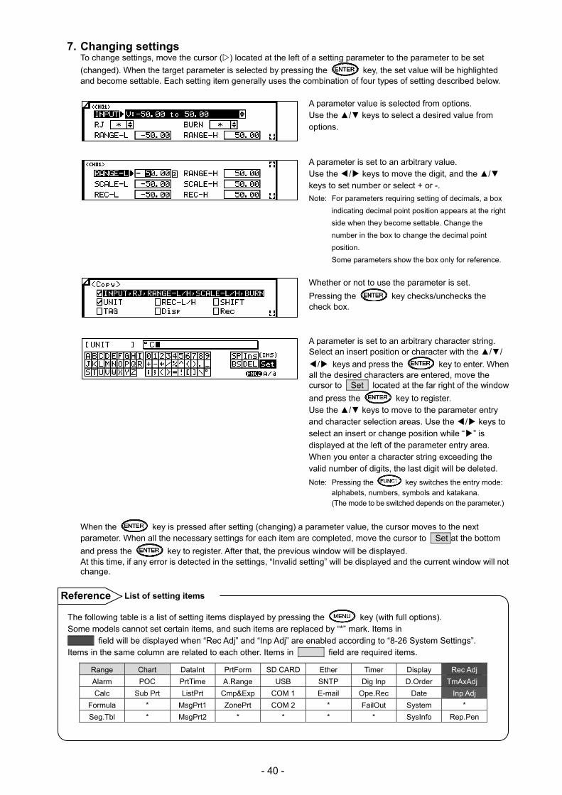
7. Changing settings To change settings, move the cursor () located at the left of a setting parameter to the parameter to be set
(changed). When the target parameter is selected by pressing the key, the set value will be highlighted and become settable. Each setting item generally uses the combination of four types of setting described below.
A parameter value is selected from options. Use the / keys to select a desired value from options.
A parameter is set to an arbitrary value. Use the / key s to move the digit, and the / keys to set number or select + or -.
Note: For parameters requiring setting of decimals, a box
indicating decimal point position appears at the right
side when they become settable. Change the
number in the box to change the decimal point
position.
Some parameters show the box only for reference.
Whether or not to use the parameter is set.
Pressing the key checks/unchecks the check box.
A parameter is set to an arbitrary character string. Select an insert position or character with the //
/ keys and press the key to enter. When all the desired characters are entered, move the cursor to Set located at the far right of the window
and press the key to register. Use the / keys to move to the parameter entry and character selection areas. Use the / keys to select an insert or change position while “” is displayed at the left of the parameter entry area. When you enter a character string exceeding the valid number of digits, the last digit will be deleted.
Note: Pressing the key switches the entry mode: alphabets, numbers, symbols and katakana. (The mode to be switched depends on the parameter.)
When the key is pressed after setting (changing) a parameter value, the cursor moves to the next parameter. When all the necessary settings for each item are completed, move the cursor to Set at the bottom
and press the key to register. After that, the previous window will be displayed. At this time, if any error is detected in the settings, “Invalid setting” will be displayed and the current window will not change.
The following table is a list of setting items displayed by pressing the key (with full options). Some models cannot set certain items, and such items are replaced by “*” mark. Items in field will be displayed when “Rec Adj” and “Inp Adj” are enabled according to “8-26 System Settings”. Items in the same column are related to each other. Items in field are required items.
Range Chart DataInt PrtForm SD CARD Ether Timer Display Rec Adj
Alarm POC PrtTime A.Range USB SNTP Dig Inp D.Order TmAxAdj
Calc Sub Prt ListPrt Cmp&Exp COM 1 E-mail Ope.Rec Date Inp Adj
Formula * MsgPrt1 ZonePrt COM 2 * FailOut System *
Seg.Tbl * MsgPrt2 * * * * SysInfo Rep.Pen
List of setting items Reference

- 41 -
8-2. Input Type Settings “Range”
Parameters including range, RJ (internal/external switching of reference junction compensation), scale and unit can be set collectively for each channel.
1. Parameters 1) Input
Set the input type (INPUT), range (RANGE-L/H) and RJ internal/external (RJ) in accordance with the sensor to be connected (thermocouple or resistance thermometer) and the target measuring range.
2) Burnout If a sensor (thermocouple or resistance thermometer) or input cable is disconnected, chart recording jumps to the upper (UP) or lower (DOWN) limit. This can be reflected to the display or output.
3) Scale
Set the scale used for display or recording of actual input after setting input type (INPUT) and range (RANGE-L/H). Scale setting (SCALE) is required when displaying/recording a voltage input from a converter with an arbitrary scale. In this case, the scale should use arbitrary scale factor of the voltage input. For thermocouple or resistance thermometer input, only the position of decimal point can be specified.
4) Chart recording range Set the recording range of chart. Specify 0% position of chart with REC-L and 100% position with REC-H.
5) Sensor correction Measurement value is offset by the specified value. Use this function to adjust the zero point.
6) Unit Arbitrary characters can be set as unit. However, when numeric characters are set, you may find it difficult to distinguish the unit from measured data at data printing. Up to six digits can be set, and upper two digits are printed only at digital printing.
Unit is set to “01”. Measured data is “291.3” in this case.
Up to five digits (six digits when including a minus sign) can be set for the upper/lower limit of range, scale and chart recording. For numeric value settings with a decimal fraction, the lower/upper range should be -30000 to 30000 and the lower/upper scale and chart recording should be -30000 to 99999 with decimals excluded.
Valid number of digits
Note
Connecting a thermocouple in parallel with another instrument may cause a trouble. If it has to be done, make sure to select “None” for burnout. Please note that the recording accuracy is not guaranteed in this case.
Set “None” for parallel operation Note

- 42 -
7) Tag
Tag name can be attached to each channel data.
8) Display, trace printing, digital recording/printing, SD card recording ON/OFF Select ON or OFF for each display/recording.
9) Input filter
The input filter has a function to stabilize the measuring input. A CR filter is mounted in the measuring circuit. In addition, a software filter (called as “input filter”) for the “primary delay computation” is also installed to smooth slight variations of the measuring input. The value for the programming is corresponding to “Time constant: T”.
T
A
0.63
Input filter: None
Input filter: T
Input filter

- 43 -
2. Parameter setting
(1) Pressing the key displays the
menu window (list of setting items).
(2) Select “Range”.
(Set contents of all channels will be
displayed.)
(3) Move the cursor to the target CH with the
/ keys and press the key. The
cursor does not move to parameters other
than CH.
Pressing the key on this window
displays the copy window for input type
settings. (See the next page for “Copying
settings”.)
(4) Move the cursor to a parameter to be set
with the // / keys.
(5) Press the key to make it available
for setting and then select or enter a value.
(6) After completing the settings of this item,
move the cursor to Set .
(7) Press the key to register the
settings (when chart recording is ON, a
setting change mark is printed). To cancel
the settings, press the key.
Note: Actual windows are separated. Use the / keys to scroll and continue settings.
CH No. is fixed to the one selected from the list of set contents. The input type, RJ, burnout and ON/OFF of each display/recording are set by selecting a value from options with the / keys. The upper/lower limit of range, scale and chart recording, and sensor correction are set by selecting a numeric value at each digit with the / keys. The unit and tag are set by selecting arbitrary characters on the window.
Parameter settings Reference
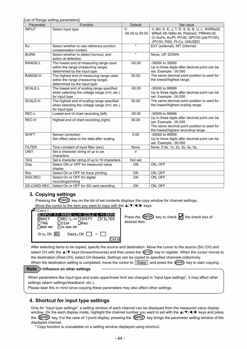
- 44 -
[List of Range setting parameters] Parameter Function Default Set value
INPUT Select input type V: -50.00 to 50.00
V, MV, K, E, J, T, R, S, B, N, U, L, WWRe26, WRe5-26, NiMo-Ni, Platinel2, PtRh40-20, Cr-AuFe, Au/Pt, Pt100, QPt100 (old Pt100), JPt100, Pt50, Pt-Co, UNUSED
RJ Select whether to use reference junction compensation contact
* EXT (external), INT (internal)
BURN Select whether to detect burnout, and action at detection
* None, UP, DOWN
RANGE-L The lowest end of measuring range used within the range (measuring range) determined by the input type
-50.00 -30000 to 30000 Up to three digits after decimal point can be set. Example: -30.000 The same decimal point position is used for the lowest/highest range.
RANGE-H The highest end of measuring range used within the range (measuring range) determined by the input type
50.00
SCALE-L The lowest end of scaling range specified when selecting the voltage range (mV, etc.) for input type
-50.00 -30000 to 99999 Up to three digits after decimal point can be set. Example: -30.000 The same decimal point position is used for the lowest/highest scaling range.
SCALE-H The highest end of scaling range specified when selecting the voltage range (mV, etc.) for input type
50.00
REC-L Lowest end of chart recording (left) -50.00 -30000 to 99999 Up to three digits after decimal point can be set. Example: -30.000 The same decimal point position is used for the lowest/highest recording range.
REC-H Highest end of chart recording (right) 50.00
SHIFT Sensor correction Set offset value to the data after scaling
0.00 -30000 to 99999 Up to three digits after decimal point can be set. Example: -30.000
FILTER Time constant of input filter (sec). None None, 0.5s, 1s, 2s, 3s, 4s, 5s, UNIT Set a character string of up to six
characters V
TAG Set a character string of up to 10 characters Not set Disp Select ON or OFF for measured value
display ON ON, OFF
Rec Select On or OFF for trace printing ON ON, OFF DIGI.REC Select On or OFF for digital
recording/printing ON ON, OFF
SD-CARD.REC Select On or OFF for SD card recording ON ON, OFF
3. Copying settings Pressing the key on the list of set contents displays the copy window for channel settings. Move the cursor to the item you want to copy with the /// keys.
Press the key to check the check box of desired item.
After selecting items to be copied, specify the source and destination. Move the cursor to the source (Src.CH) and select CH with the / keys (forward/reverse) and then press the key to register. When the cursor moves to the destination (Dest.CH), select CH likewise. Settings can be copied to specified channels collectively. When the destination setting is completed, move the cursor to Copy and press the key to start copying.
4. Shortcut for input type settings
Only for “input type settings", a setting window of each channel can be displayed from the measured value display window. On the each display mode, highlight the channel number you want to set with the // / keys and press
the key. For the case of 1-point display, pressing the key brings the parameter setting window of the displayed channel.
* Copy function is unavailable on a setting window displayed using shortcut.
When parameters like input type and scale upper/lower limit are changed in “input type settings”, it may affect other settings (alarm settings/deadband, etc.). Please bear this in mind since copying these parameters may also affect other settings.
Influence on other settings Note
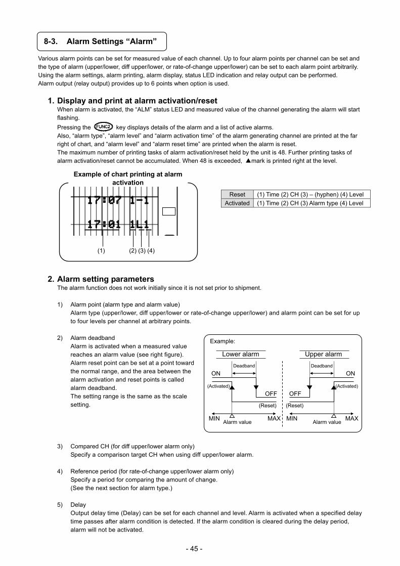
- 45 -
8-3. Alarm Settings “Alarm”
Various alarm points can be set for measured value of each channel. Up to four alarm points per channel can be set and the type of alarm (upper/lower, diff upper/lower, or rate-of-change upper/lower) can be set to each alarm point arbitrarily. Using the alarm settings, alarm printing, alarm display, status LED indication and relay output can be performed. Alarm output (relay output) provides up to 6 points when option is used.
1. Display and print at alarm activation/reset When alarm is activated, the “ALM” status LED and measured value of the channel generating the alarm will start flashing.
Pressing the key displays details of the alarm and a list of active alarms. Also, “alarm type”, “alarm level” and “alarm activation time” of the alarm generating channel are printed at the far right of chart, and “alarm level” and “alarm reset time” are printed when the alarm is reset. The maximum number of printing tasks of alarm activation/reset held by the unit is 48. Further printing tasks of alarm activation/reset cannot be accumulated. When 48 is exceeded, mark is printed right at the level.
Reset (1) Time (2) CH (3) – (hyphen) (4) Level
Activated (1) Time (2) CH (3) Alarm type (4) Level
2. Alarm setting parameters The alarm function does not work initially since it is not set prior to shipment. 1) Alarm point (alarm type and alarm value)
Alarm type (upper/lower, diff upper/lower or rate-of-change upper/lower) and alarm point can be set for up to four levels per channel at arbitrary points.
2) Alarm deadband
Alarm is activated when a measured value reaches an alarm value (see right figure). Alarm reset point can be set at a point toward the normal range, and the area between the alarm activation and reset points is called alarm deadband. The setting range is the same as the scale setting.
3) Compared CH (for diff upper/lower alarm only)
Specify a comparison target CH when using diff upper/lower alarm. 4) Reference period (for rate-of-change upper/lower alarm only)
Specify a period for comparing the amount of change. (See the next section for alarm type.)
5) Delay
Output delay time (Delay) can be set for each channel and level. Alarm is activated when a specified delay time passes after alarm condition is detected. If the alarm condition is cleared during the delay period, alarm will not be activated.
Example:
Lower alarm
Deadband
(Activated)
(Reset)
Alarm value MIN MAX
Upper alarm
ON
OFF
Deadband
(Activated)
(Reset)
Alarm valueMIN MAX
ON
OFF
(1) (2) (3) (4)
Example of chart printing at alarm activation

- 46 -
6) Output Alarm condition (activation/reset) at each alarm point is output from the relay of the specified No. (alarm output terminal No.). This output is not performed initially because it is set to “-“ prior to shipment. Output relay can be specified arbitrarily for each channel and level (from No.1 to 6 relay: optional). When “99” is specified, internal circuit output can be performed instead of relay output. The internal ON/OFF signal can be used as a trigger for SD card recording or mail sending (optional).
7) Output mode (AND/OR)
Select the circuit type (AND/OR) for output. Multiple alarm points can be assigned to one relay No. AND output: .... Relay turns ON when all the assigned
alarm points generate alarm. OR output: ...... Relay turns ON when any of the
assigned alarm points generates alarm.
8) Holding/not holding conditions of measured value display, status LED and relay output at alarm activation When alarm is activated, the measured value and “ALM” start flashing. When the alarm is reset, the measured value stops flashing and “ALM” is turned off (they keep flashing when alarm display and relay output is held). You can stop flashing of measured value and status LED from the alarm status check window if the alarm has been reset. When remote contact is selected as a reset method, specify the remote contact No. which executes a reset (Hold-EX).
Not Hold Hold: Reset by KEY Hold: Reset by EX
Select a reset method (key operation or remote contact).
Alarm point 1
Alarm point 2
AND output
OR output
The status LED and output cannot be reset while alarm is activated. Even when alarm is reset, the condition of display, status LED and output at alarm activation are held. Specify a reset method for these items.
Alarm confirmation and output status Note
Alarm reset
Alarm activation
Measured value stays on
Measured value flashes
“ALM” OFF
“ALM”flashes
Relay output OFF
Relay output ON
Reset by KEY/EX
Alarm reset
Alarm activation
Measured value stays on
Measured value flashes
“ALM” OFF
“ALM” flashes
Relay output OFF
Relay output ON
Reset by KEY/EX
Alarm reset
Alarm activation
Measured value stays on
Measured value flashes
“ALM” OFF
“ALM” flashes
Relay output OFF
Relay output ON
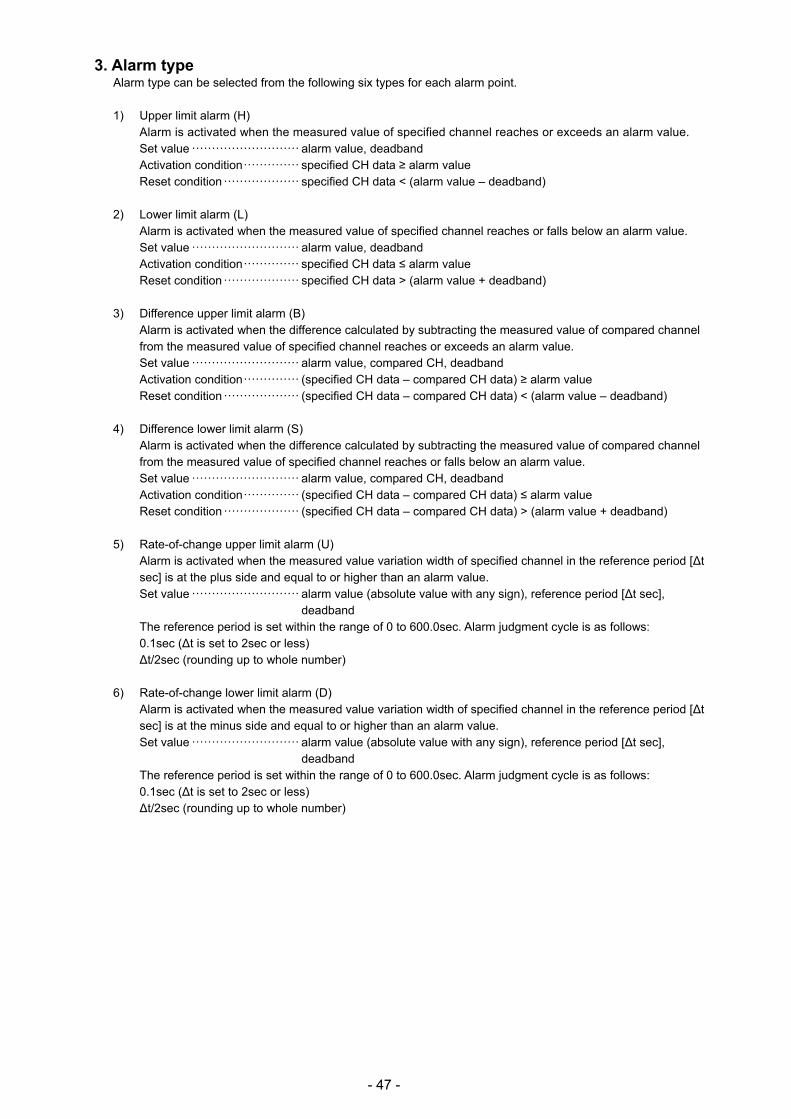
- 47 -
3. Alarm type Alarm type can be selected from the following six types for each alarm point. 1) Upper limit alarm (H)
Alarm is activated when the measured value of specified channel reaches or exceeds an alarm value. Set value ··························· alarm value, deadband Activation condition ·············· specified CH data ≥ alarm value Reset condition ··················· specified CH data < (alarm value – deadband)
2) Lower limit alarm (L) Alarm is activated when the measured value of specified channel reaches or falls below an alarm value. Set value ··························· alarm value, deadband Activation condition ·············· specified CH data ≤ alarm value Reset condition ··················· specified CH data > (alarm value + deadband)
3) Difference upper limit alarm (B) Alarm is activated when the difference calculated by subtracting the measured value of compared channel from the measured value of specified channel reaches or exceeds an alarm value. Set value ··························· alarm value, compared CH, deadband Activation condition ·············· (specified CH data – compared CH data) ≥ alarm value Reset condition ··················· (specified CH data – compared CH data) < (alarm value – deadband)
4) Difference lower limit alarm (S) Alarm is activated when the difference calculated by subtracting the measured value of compared channel from the measured value of specified channel reaches or falls below an alarm value. Set value ··························· alarm value, compared CH, deadband Activation condition ·············· (specified CH data – compared CH data) ≤ alarm value Reset condition ··················· (specified CH data – compared CH data) > (alarm value + deadband)
5) Rate-of-change upper limit alarm (U) Alarm is activated when the measured value variation width of specified channel in the reference period [∆t sec] is at the plus side and equal to or higher than an alarm value. Set value ··························· alarm value (absolute value with any sign), reference period [∆t sec],
deadband The reference period is set within the range of 0 to 600.0sec. Alarm judgment cycle is as follows: 0.1sec (∆t is set to 2sec or less) ∆t/2sec (rounding up to whole number)
6) Rate-of-change lower limit alarm (D) Alarm is activated when the measured value variation width of specified channel in the reference period [∆t sec] is at the minus side and equal to or higher than an alarm value. Set value ··························· alarm value (absolute value with any sign), reference period [∆t sec],
deadband The reference period is set within the range of 0 to 600.0sec. Alarm judgment cycle is as follows: 0.1sec (∆t is set to 2sec or less) ∆t/2sec (rounding up to whole number)
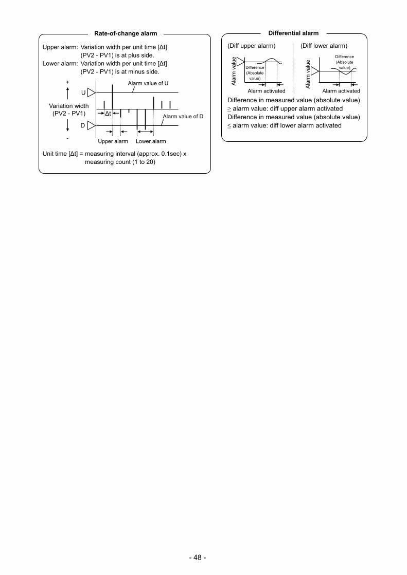
- 48 -
Upper alarm: Variation width per unit time [∆t]
(PV2 - PV1) is at plus side. Lower alarm: Variation width per unit time [∆t]
(PV2 - PV1) is at minus side.
Unit time [∆t] = measuring interval (approx. 0.1sec) x measuring count (1 to 20)
∆t Variation width
(PV2 - PV1)
-
+
D
U
Upper alarm Lower alarm
Alarm value of D
Alarm value of U
Rate-of-change alarm Difference in measured value (absolute value) ≥ alarm value: diff upper alarm activated Difference in measured value (absolute value) ≤ alarm value: diff lower alarm activated
(Diff upper alarm)
Alarm activated
Ala
rm v
alue
Difference(Absolute
value)
Alarm activated
Ala
rm v
alue
Difference(Absolute
value)
(Diff lower alarm)
Differential alarm

- 49 -
4. Parameter settings
(1) Pressing the key displays the menu window (list of setting items).
(2) Select “Alarm”. (3) Move the cursor to the target channel with
the / keys and press the key. The cursor does not move to parameters other than CH.
Pressing the key on this window allows you to change the alarm level.
Pressing the key displays the copy window for alarm settings.
(4) Move the cursor to the parameter to be set
with the /// keys.
(5) Press the key to make it available for setting and then select or enter a value.
(6) After completing the settings of this item, move the cursor to Set .
(7) Press the key to register the settings (when chart recording is ON, a setting change mark is printed). To cancel
the settings, press the key.
Note: Actual windows are separated. Use the / keys to scroll and continue settings.
The decimal point position of alarm value/deadband is linked to that of scale set value. Therefore, when the decimal point position of scale is changed in “8-2. Input Type Settings”, the decimal point position of alarm value/deadband will also be changed. Also, alarm deadband is set to an absolute value.
Relation with the decimal point position of scale set value Note
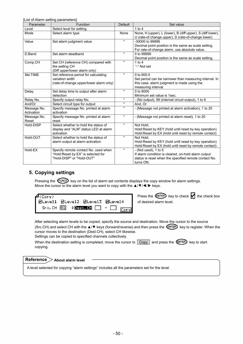
- 50 -
[List of Alarm setting parameters] Parameter Function Default Set value
Level Select level for setting 1 to 4 Mode Select alarm type None None, H (upper), L (lower), B (diff upper), S (diff lower),
U (rate-of change upper), D (rate-of-change lower) Value Set alarm judgment value * -30000 to 99999
Decimal point position is the same as scale setting. For rate-of-change alarm, use absolute value.
D.Band Set alarm deadband * 0 to 99999 Decimal point position is the same as scale setting.
Comp.CH Set CH (reference CH) compared with the setting CH (Diff upper/lower alarm only)
* 1 to 4 “-“ Not set
Std.TIME Set reference period for calculating variation width (rate-of-change upper/lower alarm only)
* 0 to 600.0 Set period can be narrower than measuring interval. In this case, alarm judgment is made using the measuring interval.
Delay Set delay time to output after alarm detection
* 0 to 6000 Minimum set value is 1sec.
Relay No. Specify output relay No. * - (No output), 99 (internal circuit output), 1 to 6 And/Or Select circuit type for output * And, Or Message No. Activation
Specify message No. printed at alarm activation
* - (Message not printed at alarm activation), 1 to 20
Message No. Reset
Specify message No. printed at alarm reset
* - (Message not printed at alarm reset), 1 to 20
Hold-DISP Select whether to hold the status of display and “ALM” status LED at alarm activation
* Not Hold, Hold:Reset by KEY (hold until reset by key operation)Hold:Reset by EX (hold until reset by remote contact)
Hold-OUT Select whether to hold the status of alarm output at alarm activation
* Not Hold, Hold:Reset by KEY (hold until reset by key operation)Hold:Reset by EX (hold until reset by remote contact)
Hold-EX Specify remote contact No. used when “Hold:Reset by EX” is selected for "Hold-DISP" or "Hold-OUT"
* - (Not used), 1 to 5 If alarm condition is cleared, on-hold alarm output status is reset when the specified remote contact No. turns ON.
5. Copying settings
Pressing the key on the list of alarm set contents displays the copy window for alarm settings. Move the cursor to the alarm level you want to copy with the /// keys.
Press the key to check the check box
of desired alarm level.
After selecting alarm levels to be copied, specify the source and destination. Move the cursor to the source
(Src.CH) and select CH with the / keys (forward/reverse) and then press the key to register. When the cursor moves to the destination (Dest.CH), select CH likewise. Settings can be copied to specified channels collectively.
When the destination setting is completed, move the cursor to Copy and press the key to start copying.
A level selected for copying “alarm settings” includes all the parameters set for the level.
About alarm level Reference
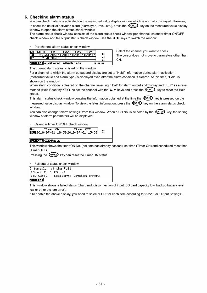
- 51 -
6. Checking alarm status You can check if alarm is activated on the measured value display window which is normally displayed. However,
to check the detail of activated alarm (alarm type, level, etc.), press the key on the measured value display window to open the alarm status check window. The alarm status check window consists of the alarm status check window per channel, calendar timer ON/OFF check window and fail output status check window. Use the / keys to switch the window.
• Per-channel alarm status check window Select the channel you want to check. The cursor does not move to parameters other than CH.
The current alarm status is listed on the window. For a channel to which the alarm output and display are set to “Hold”, information during alarm activation (measured value and alarm type) is displayed even after the alarm condition is cleared. At this time, “Hold” is shown on the window. When alarm condition is cleared on the channel selecting “Hold” for alarm output and display and “KEY” as a reset
method (Hold:Reset by KEY), select the channel with the / keys and press the key to reset the Hold status.
This alarm status check window contains the information obtained at the time the key is pressed on the
measured value display window. To view the latest information, press the key on the alarm status check window.
You can also change "alarm settings" from this window. When a CH No. is selected by the key, the setting window of alarm parameters will be displayed.
• Calendar timer ON/OFF check window
This window shows the timer ON No. (set time has already passed), set time (Timer ON) and scheduled reset time (Timer OFF).
Pressing the key can reset the Timer ON status.
• Fail output status check window
This window shows a failed status (chart end, disconnection of input, SD card capacity low, backup battery level low or other system error). * To enable the above display, you need to select “LCD” for each item according to “8-22. Fail Output Settings”.
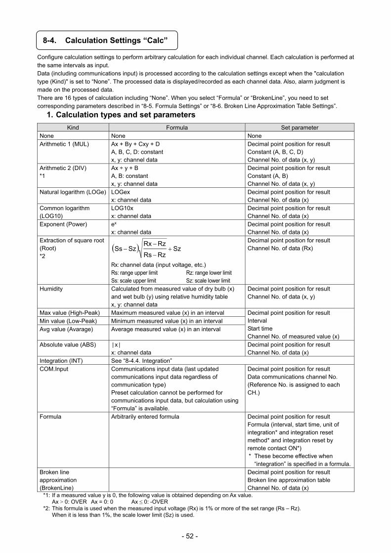
- 52 -
8-4. Calculation Settings “Calc”
Configure calculation settings to perform arbitrary calculation for each individual channel. Each calculation is performed at the same intervals as input. Data (including communications input) is processed according to the calculation settings except when the "calculation type (Kind)" is set to “None”. The processed data is displayed/recorded as each channel data. Also, alarm judgment is made on the processed data. There are 16 types of calculation including “None”. When you select “Formula” or “BrokenLine”, you need to set corresponding parameters described in “8-5. Formula Settings” or “8-6. Broken Line Approximation Table Settings”.
1. Calculation types and set parameters
Kind Formula Set parameter None None None Arithmetic 1 (MUL) Ax + By + Cxy + D
A, B, C, D: constant x, y: channel data
Decimal point position for result Constant (A, B, C, D) Channel No. of data (x, y)
Arithmetic 2 (DIV) *1
Ax ÷ y + B A, B: constant x, y: channel data
Decimal point position for result Constant (A, B) Channel No. of data (x, y)
Natural logarithm (LOGe) LOGex x: channel data
Decimal point position for result Channel No. of data (x)
Common logarithm (LOG10)
LOG10x x: channel data
Decimal point position for result Channel No. of data (x)
Exponent (Power) ex
x: channel data Decimal point position for result Channel No. of data (x)
Extraction of square root (Root) *2
SzRzRs
RzRxSzSs
Rx: channel data (input voltage, etc.) Rs: range upper limit Rz: range lower limit Ss: scale upper limit Sz: scale lower limit
Decimal point position for result Channel No. of data (Rx)
Humidity Calculated from measured value of dry bulb (x) and wet bulb (y) using relative humidity table x, y: channel data
Decimal point position for result Channel No. of data (x, y)
Max value (High-Peak) Maximum measured value (x) in an interval Decimal point position for result Interval Start time Channel No. of measured value (x)
Min value (Low-Peak) Minimum measured value (x) in an interval Avg value (Avarage) Average measured value (x) in an interval
Absolute value (ABS) x x: channel data
Decimal point position for result Channel No. of data (x)
Integration (INT) See “8-4.4. Integration” COM.Input Communications input data (last updated
communications input data regardless of communication type) Preset calculation cannot be performed for communications input data, but calculation using “Formula” is available.
Decimal point position for result Data communications channel No. (Reference No. is assigned to each CH.)
Formula Arbitrarily entered formula Decimal point position for result Formula (interval, start time, unit of integration* and integration reset method* and integration reset by remote contact ON*) * These become effective when
“integration” is specified in a formula.Broken line approximation (BrokenLine)
Decimal point position for result Broken line approximation table Channel No. of data (x)
*1: If a measured value y is 0, the following value is obtained depending on Ax value. Ax > 0: OVER Ax = 0: 0 Ax ≤ 0: -OVER
*2: This formula is used when the measured input voltage (Rx) is 1% or more of the set range (Rs – Rz). When it is less than 1%, the scale lower limit (Sz) is used.
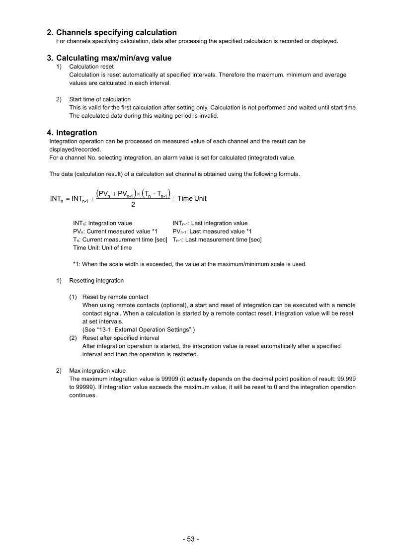
- 53 -
2. Channels specifying calculation For channels specifying calculation, data after processing the specified calculation is recorded or displayed.
3. Calculating max/min/avg value 1) Calculation reset
Calculation is reset automatically at specified intervals. Therefore the maximum, minimum and average values are calculated in each interval.
2) Start time of calculation
This is valid for the first calculation after setting only. Calculation is not performed and waited until start time. The calculated data during this waiting period is invalid.
4. Integration Integration operation can be processed on measured value of each channel and the result can be displayed/recorded. For a channel No. selecting integration, an alarm value is set for calculated (integrated) value. The data (calculation result) of a calculation set channel is obtained using the following formula.
Unit Time
2
T-TPVPVINTINT 1-nn1-nn
1-nn
INTn: Integration value INTn-1: Last integration value PVn: Current measured value *1 PVn-1: Last measured value *1 Tn: Current measurement time [sec] Tn-1: Last measurement time [sec] Time Unit: Unit of time
*1: When the scale width is exceeded, the value at the maximum/minimum scale is used.
1) Resetting integration
(1) Reset by remote contact When using remote contacts (optional), a start and reset of integration can be executed with a remote contact signal. When a calculation is started by a remote contact reset, integration value will be reset at set intervals. (See “13-1. External Operation Settings”.)
(2) Reset after specified interval After integration operation is started, the integration value is reset automatically after a specified interval and then the operation is restarted.
2) Max integration value The maximum integration value is 99999 (it actually depends on the decimal point position of result: 99.999 to 99999). If integration value exceeds the maximum value, it will be reset to 0 and the integration operation continues.
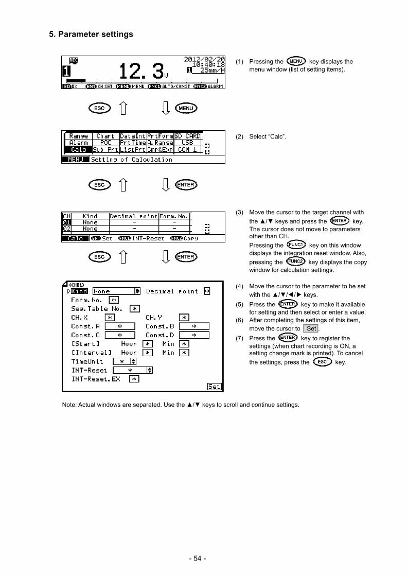
- 54 -
5. Parameter settings
(1) Pressing the key displays the menu window (list of setting items).
(2) Select “Calc”. (3) Move the cursor to the target channel with
the / keys and press the key. The cursor does not move to parameters other than CH.
Pressing the key on this window displays the integration reset window. Also,
pressing the key displays the copy window for calculation settings.
(4) Move the cursor to the parameter to be set
with the /// keys.
(5) Press the key to make it available for setting and then select or enter a value.
(6) After completing the settings of this item, move the cursor to Set .
(7) Press the key to register the settings (when chart recording is ON, a setting change mark is printed). To cancel
the settings, press the key.
Note: Actual windows are separated. Use the / keys to scroll and continue settings.

- 55 -
[List of Calc setting parameters] Parameter Function Default Set value
Kind Select calculation type None None (No calculation), Root (square root), LOGe (natural logarithm), LOG10 (common logarithm), INT (integration), Humidity (humidity/temperature calculation) COM.Input (data communications input), MUL (arithmetic 1), DIV (arithmetic 2), High-Peak (max value), Low-Peak (min value), Average (average calculation), Power (exponent), ABS (absolute value calculation) Formula, BrokenLine (broken line approximation)
Decimal point Set decimal point position for result * 0 to 3 Form.No. Specify formula No. when “Formula”
is selected for Kind * - (None), 1 to 12
Seg.Table No. Specify broken line table No. when “BrokenLine” is selected for Kind
* - (None), 1 to 6
CH.X Specify CH for X data used by each calculation
* - (None), 1 to 4
CH.Y Specify CH for Y data used by each calculation
* - (None), 1 to 4
Const.A Set calculation constant A when arithmetic 1 or 2 is selected for Kind
* -30000 to 99999 Up to three digits after decimal point can be set. Example: -30.000
Const.B Set calculation constant B when arithmetic 1 or 2 is selected for Kind
* -30000 to 99999 Up to three digits after decimal point can be set. Example: -30.000
Const.C Set calculation constant C when arithmetic 1 is selected for Kind
* -30000 to 99999 Up to three digits after decimal point can be set. Example: -30.000
Const.D Set calculation constant D when arithmetic 1 is selected for Kind
* -30000 to 99999 Up to three digits after decimal point can be set. Example: -30.000
[Start] Set calculation start time Calculation is waited until set time (data during the waiting period is invalid).
* - (None), 00 : 00 to 23 : 59 When “-“ is set, following operations are performed. Integration: Operated by external reset Formula: Operated at power-on or immediately after
setting is made [Interval] Set calculation interval
For calculations using integration, integration value is reset at set intervals.
* - (None), 00 : 00 to 24 : 59 Setting “-“ or “00 : 00” disables interval.
TimeUnit Unit of integration time * Hour, Min, Sec INT-Reset Set integration reset method for
calculations using integration * None (reset not performed), Interval (specified interval),
EX (All) (all reset by remote contact), EX (individual reset by remote contact)
INT-Reset.EX Specify remote contact No. used when “EX” is selected for "INT-Reset"
* - (None), 1 to 5

- 56 -
8-5. Formula Settings “Formula”
Set a formula used when “Formula” is selected for Kind in "calculation settings". Up to 12 formulas, which are shared by all channels, can be registered using a character string consisting of 50 characters at maximum.
1. Calculation type Arithmetic operation
Four arithmetic operations
are performed.
Symbol Example Note
Addition + X + Y
Subtraction - X - Y
Multiplication * X * Y
Division / X / Y
Remainder % X % Y
Power ^ X ^ Y
* X and Y represent formula or numeric value.
Comparison operation Result is expressed by 1
(true) or 0 (false).
Symbol Example Note
Equal == X == Y
Unequal != X != Y
Greater than >> X >> Y
Less than << X << Y
Greater than or equal to >= X >= Y
Less than or equal to <= X <= Y
* X and Y represent formula or numeric value.
Logical operation Logical operation is
performed and either 1 or 0
is returned as a result.
Symbol Example Note
Logical AND AND X AND Y Parenthesize formula target
Logical OR OR X OR Y Parenthesize formula target
Exclusive OR XOR X XOR Y Parenthesize formula target
Negation NOT NOT( X ) Parenthesize negation
target
* X and Y represent formula or numeric value. X and Y should indicate 0 or 1.
General calculation functions Function calculation is
performed.
Symbol Example Note
Round up to whole number CEL CEL( X )
Round down to whole number FLR FLR( X )
Absolute value ABS ABS( X )
Square root SQR SQR( X )
Power of e EXP EXP( X )
Natural logarithm (bottom e) LOG LOG( X )
Common logarithm
(bottom 10)
LOG10 LOG10( X )
* X represents formula or numeric value.
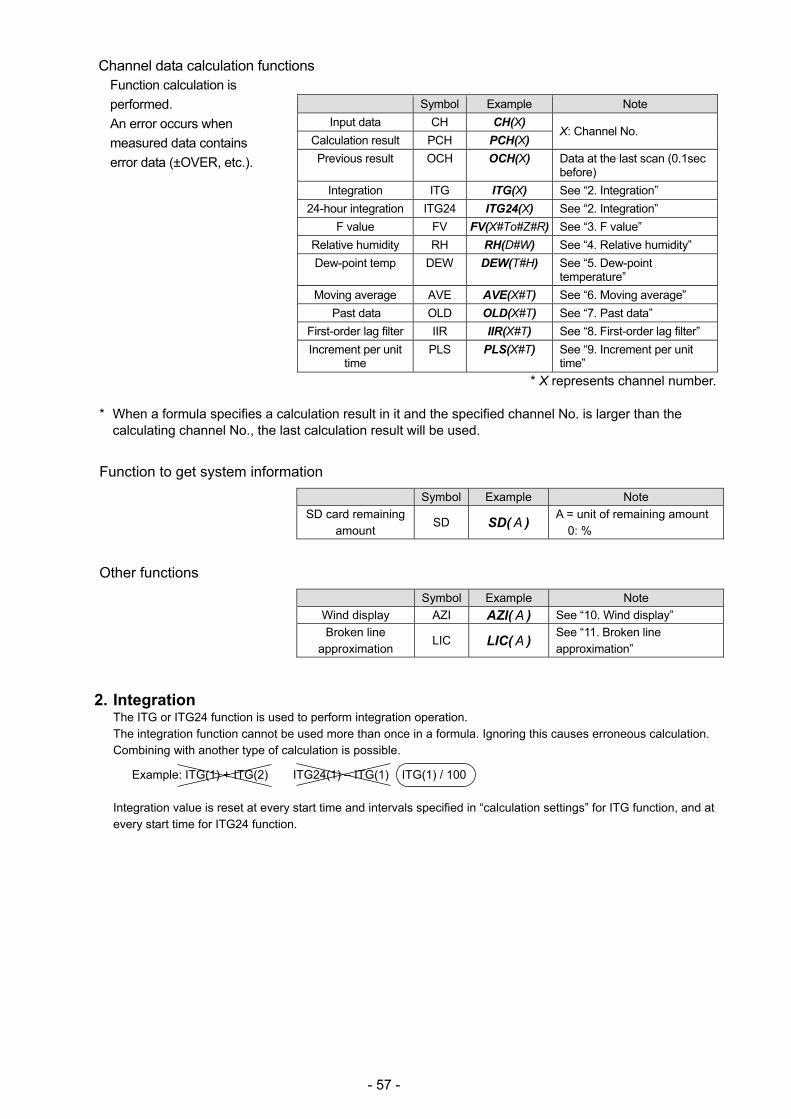
- 57 -
Channel data calculation functions Function calculation is
performed.
An error occurs when
measured data contains
error data (±OVER, etc.).
Symbol Example Note
Input data CH CH(X) X: Channel No.
Calculation result PCH PCH(X)
Previous result OCH OCH(X) Data at the last scan (0.1sec before)
Integration ITG ITG(X) See “2. Integration”
24-hour integration ITG24 ITG24(X) See “2. Integration”
F value FV FV(X#To#Z#R) See “3. F value”
Relative humidity RH RH(D#W) See “4. Relative humidity”
Dew-point temp DEW DEW(T#H) See “5. Dew-point temperature”
Moving average AVE AVE(X#T) See “6. Moving average”
Past data OLD OLD(X#T) See “7. Past data”
First-order lag filter IIR IIR(X#T) See “8. First-order lag filter”
Increment per unit time
PLS PLS(X#T) See “9. Increment per unit time”
* X represents channel number.
* When a formula specifies a calculation result in it and the specified channel No. is larger than the calculating channel No., the last calculation result will be used.
Function to get system information
Symbol Example Note
SD card remaining amount
SD SD( A ) A = unit of remaining amount
0: %
Other functions
Symbol Example Note
Wind display AZI AZI( A ) See “10. Wind display”
Broken line approximation
LIC LIC( A ) See “11. Broken line approximation”
2. Integration The ITG or ITG24 function is used to perform integration operation. The integration function cannot be used more than once in a formula. Ignoring this causes erroneous calculation. Combining with another type of calculation is possible.
Example: ITG(1) + ITG(2) ITG24(1) – ITG(1) ITG(1) / 100 Integration value is reset at every start time and intervals specified in “calculation settings” for ITG function, and at every start time for ITG24 function.

- 58 -
1) Normal integration Integration value is reset at every reference time and interval. Entering a formula ITG(X)
X: Channel No. of integration target
Calculation detail Dn = Dn-1 + (PVn + PVn-1) x (Tn-Tn-1) ÷ 2 Dn: Integration result Dn-1: Last integration result PVn: Integration target data PVn-1: Last integration target data Tn: Calculation time Tn-1: Last calculation time
If error data (±OVER, etc.) is included, calculation will not be performed and the last result will be valid.
2) 24-hour integration
Integration value is reset only at reference time (start time). Entering a formula ITG24(X)
X: Channel No. of integration target
Calculation detail is the same as normal integration.
3. F value Entering a formula
FV(X#To#Z#R) X: Channel No. of calculation target, To: Reference temperature for F value calculation, Z: Z value, R: Start temperature for F value calculation
F value is obtained from the following calculation.
∫10Adt where A = (T - To) ÷ Z T: Calculation target channel data
When T value exceeds R value, F value will be reset to 0.
4. Relative humidity Entering a formula
RH(D#W) D: Channel No. of dry bulb temperature, W: Channel No. of wet bulb temperature
Relative humidity is obtained from the following formula. ((B - 0.000662 x 1013.0 x (Ddata - Wdata)) ÷ A) x 100 A: Dry bulb saturated water vapor pressure, B: Wet bulb saturated water vapor pressure, Ddata: Dry bulb temperature, Wdata: Wet bulb temperature The following formula is used to obtain a value of saturated water vapor pressure.
6.1121 x EXP ((17.502 x T) ÷ (240.9 + T)) T: Temperature
- 59 -
5. Dew-point temperature Entering a formula
DEW(T#H) T: Channel No. of temperature data, H: Channel No. of relative humidity
Dew-point temperature is obtained from the following calculation.
t: Temperature data h: Relative humidity data D: Dew-point temperature
(1) K = t + 273.15 (2) When t ≥ 0: W = EXP (-5800.2206 / K + 1.3914993 + K x (-0.048640239 + K x (0.41764768E-4
- 0.14452093E-7 x K)) + 6.5459673 x LOG(K)) / 1000 When t < 0:
W = EXP (-5674.5359 / K + 6.3925247 + K x (-9.677843E-3 + K x (0.62215701E-6 + K x (0.20747825E-8 - 9.484024E-13 x K))) + 4.1635019 x LOG(K)) / 1000
(3) S = W x h / 100 (4) P = S x 1000 (5) Y = LOG(P) (6) When P ≥ 611.2: D = -77.199 + Y x (13.198 + Y x (-0.63772 + 0.071098 x Y)) When P < 611.2: D = -60.662 + Y x (7.4624 + Y x (0.20594 + 0.016321 x Y))
6. Moving average Entering a formula
AVE(X#T) X: Data channel No., T: Time-line range (x 0.1sec)
An average value in the past T seconds is calculated.
AVE
Sampling period 0.1sec
T range 1 to 10 (x 0.1sec)
7. Past data Entering a formula
OLD(X#T) X: Data channel No., T: Backward time (x 0.1sec)
Data obtained T seconds before is acquired.
OLD
Sampling period 0.1sec
T range 1 to 10(x 0.1sec)

- 60 -
8. First-order lag filter Entering a formula
IIR(X#T) X: Data channel No., T: Time constant (x 0.1 sec)
First-order lag filter calculation is processed on the channel X data.
Calculation detail
dt ÷ (dt + t) x (x – d) + d dt: Sampling time t: Time constant x: Current value of channel X d: Last calculation result
9. Increment per unit time Entering a formula
PLS(X#T) X: Data channel No., T: Unit time (1 to 10 x 0.1sec)
Increment per unit time is calculated. Specify a channel selecting integration operation for X.
When using PLS function, the data will be invalid when a reset of integration value occurs at a set time or by another reason except overflow (because the same process as overflow reset is performed internally). Formulate the operation in consideration of reset of integration value.
10. Wind display Entering a formula
AZI(A) A: Wind data
Wind display is made by converting numeric data into direction. See the following table for the relation between wind data and displayed direction. When A has a decimal fraction, the nearest direction will be displayed. Example: 1.2 → NNE
A Display A Display • • •
• • •
8 S 9 SSW 10 SW
-3 WNW 11 WSW -2 NW 12 W -1 NNW 13 WNW 0 N 14 NW 1 NNE 15 NNW 2 NE 16 N 3 ENE 17 NNE 4 E 18 NE 5 ESE •
• •
• • •
6 SE 7 SSE
Also, the scale of the channel selecting wind display as calculation type uses wind scale.
- 61 -
11. Broken line approximation Entering a formula
LIC(X#A) X: Data channel No. A: Defined broken line approximation table No.
"Broken line approximation" can be added in a formula, and the first-order approximation can be performed for up to 30 broken lines. Broken line is defined separately using up to six tables, and the table No. is specified in a formula (see “8-6. Broken Line Approximation Table Settings”). Calculation is performed using the following formula according to the specified table parameters. An < X1 < An+1 (Bn+1 - Bn) / (An+1 - An) x (X1 - An) + Bn
12. Examples of combining different operations (CH(1) * 3 – 20) / 6
(“Channel 1 raw data” x 3 - 20) ÷ 6
(CH(1) + CH(2)) << 300 Result will be 1 when the sum of channel 1 and channel 2 raw data is smaller than 300.
ABS(CH(1)) >= 50 Result will be 1 when the absolute value of channel 1 is greater than or equal to 50.
(PCH(1) >= 100) AND (PCH(2) <= 50) Result will be 1 when the channel 1 data is greater than or equal to 100, and the channel 2 data is less than or equal to 50.
Following functions cannot be combined together. Combining these functions causes calculation error.
ITG, ITG24, AVE, AVEH, OLD, OLDH, IIR Example of formula which delivers a false result: AVE(OLD(1#10)#60)
Combination of functions Note

- 62 -
13. Parameter settings
(1) Pressing the key displays the menu window (list of setting items).
(2) Select “Formula”. (3) Move the cursor to the target formula No.
with the / keys and press the key. The cursor does not move to parameters other than formula No.
Also, pressing the key on this window displays the copy window for formula settings.
(4) Press the key to make it available for setting and then enter a formula.
(5) After completing the setting of this item, move the cursor to Set .
(6) Press the key to register the setting (when chart recording is ON, a setting change mark is printed). To cancel
the setting, press the key.
[Formula setting parameter] Parameter Function Default Set value
Formula Set formula used when “Formula” is selected as "calculation type" using up to 50 characters
Not set

- 63 -
8-6. Broken Line Approximation Table Settings “Seg.Tbl”
Set the table used when “BrokenLine” is selected as calculation type. Up to six tables can be set, and up to 30 points can be set to each table. For channels selecting “BrokenLine” as calculation type, a table can be selected individually from six options.
(1) Pressing the key displays the menu window (list of setting items).
(2) Select “Seg.Tbl”.
(3) Pressing the key advances the
table number. Press the key to select the target table.
Also, pressing the key on this window displays the copy window for table settings.
(4) Move the cursor to the parameter to be set
with the /// keys.
(5) Press the key to make it available for setting and then enter a value.
(6) After completing the settings of this item, move the cursor to Set .
(7) Press the key to register the settings (when chart recording is ON, a setting change mark is printed). To cancel
the settings, press the key.
[List of Seg.Tbl setting parameters] Parameter Function Default Set value
X.Dot Set decimal point position of X axis factor 0 0 to 3 Y.Dot Set decimal point position of Y axis factor 0 0 to 3 X-01 to X-30 Set X1 to X30 of broken line approximation
table - - (Not set), -30000 to 99999
When “-“ is selected, subsequent X factor settings will be disabled.
Y-01 to Y-30 Set Y1 to Y30 of broken line approximation table
- - (Not set), -30000 to 99999 When “-“ is selected, subsequent Y factor settings will be disabled.
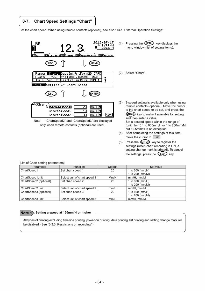
- 64 -
8-7. Chart Speed Settings “Chart”
Set the chart speed. When using remote contacts (optional), see also “13-1. External Operation Settings”.
(1) Pressing the key displays the menu window (list of setting items).
(2) Select “Chart”. (3) 3-speed setting is available only when using
remote contacts (optional). Move the cursor to the chart speed to be set, and press the
key to make it available for setting and then enter a value. Set a desired speed within the range of (unit: 1mm) 1 to 600mm/H or 1 to 200mm/M, but 12.5mm/H is an exception.
(4) After completing the settings of this item, move the cursor to Set .
(5) Press the key to register the settings (when chart recording is ON, a setting change mark is printed). To cancel
the settings, press the key.
[List of Chart setting parameters] Parameter Function Default Set value
ChartSpeed1 Set chart speed 1 20 1 to 600 (mm/H) 1 to 200 (mm/M)
ChartSpeed1unit Select unit of chart speed 1 Mm/H mm/H, mm/M ChartSpeed2 (optional) Set chart speed 2 20 1 to 600 (mm/H)
1 to 200 (mm/M) ChartSpeed2 unit Select unit of chart speed 2 mm/H mm/H, mm/M ChartSpeed3 (optional) Set chart speed 3 20 1 to 600 (mm/H)
1 to 200 (mm/M) ChartSpeed3 unit Select unit of chart speed 3 Mm/H mm/H, mm/M
Note: “ChartSpeed2” and “ChartSpeed3” are displayed only when remote contacts (optional) are used.
All types of printing excluding time line printing, power-on printing, data printing, list printing and setting change mark will be disabled. (See “6-3.3. Restrictions on recording”.)
Setting a speed at 150mm/H or higher Note 1

- 65 -
8-8. Time axis synchronization “POC”
This function is applicable to multiple pen type (2-pen, 3-pen and 4-pen types). The function adjusts time axis gaps between the each pen and print at the same moment on the chart.
1. Pen interval In the standard printings, data at the same moment are not able to print on the chart paper with time axis due to the time axis gaps between the each pen. When the time axis synchronization is ON, the data for the gaps are stored in memory and when the chart paper is fed to the printing start point of the 1st pen, the stored data are printed. The printing except for the 1st pen are not executed at the real time, however there will be no time axis gaps the on the chart.
2. Operation at turning on the power supply When using the recorder as first time, 2nd pen, 3rd pen and 4th pen wait at left side until the chart is fed to the 1st pen starting time axis. Using the recorder after the first time (power OFF to power ON), 2nd pen, 3rd pen, and 4th pen move as the 1st pen, however until they reach the 1st pen starting time axis, they print previous (before power OFF) data. Subsequently, printing is done at previous data not real-time data.
Printing OFF
When the printing is ON, 2nd pen stores data of gaps (G1) to 1st pen in memory and start printing on same time axis as 1st pen. When the printing is OFF, the data of gaps (G2) to 1st pen are deleted.
G2
G1
Time axis synchronization executed
[Pen gaps]
Plotter pen ·········· 1st pen: 5.0mm
1st pen ················ 2nd pen: 3.0mm
2nd pen ··············· 3rd pen: 3.0mm
3rd pen ··············· 4th pen: 3.0mm
Installation position for SR100
(1) Time axis synchronization is OFF at the default
setting. (2) Turn OFF the time axis synchronization to observe
current indication and execute input adjustment.
Reference Switching of time axis synchronization ON/OFF
<Printing EX. 1> Time axis synchronization not executed
<Printing EX. 2> Printing operation ON/OFF at time axis
synchronization executed
1st pen 2nd pen
Printing ON
When the power supply is ON, 2nd pen prints data of gaps (G1: stored data in memory prior to the power OFF) to 1st pen. While the Power supply is OFF, data of gaps to1st pen (G2) is stored.
<Printing EX. 3> Power supply ON/OFF at time axis
synchronization executed
G2
G1 Power OFF
Power ON
2nd pen1st pen
Changing the setting of the chart speed clears memory of 2nd pen, 3rd pen and 4th pen. Therefore, 2nd pen,
3rd pen and 4th pen wait at left side until they reach 1st pen starting time axis.
Note Change of the chart speed
1st pen 2nd pen
Printing OFF
Time axis synchronization not executed
Printing ON
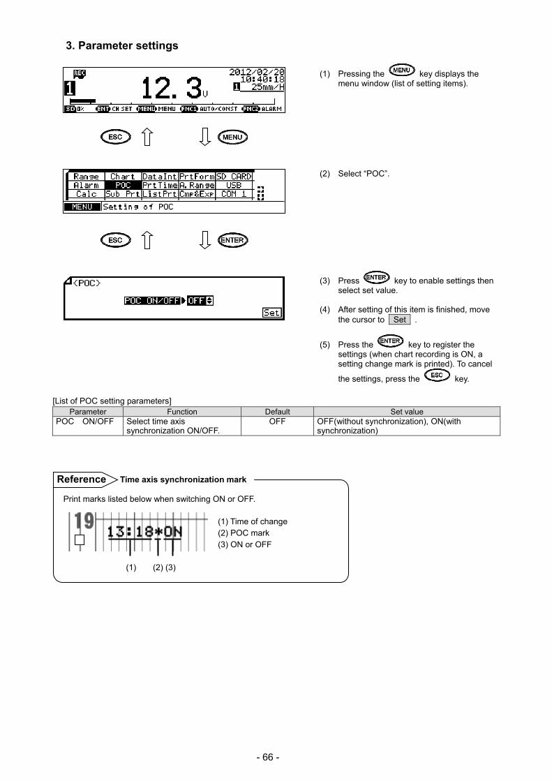
- 66 -
3. Parameter settings
(1) Pressing the key displays the menu window (list of setting items).
(2) Select “POC”.
(3) Press key to enable settings then select set value.
(4) After setting of this item is finished, move
the cursor to Set .
(5) Press the key to register the settings (when chart recording is ON, a setting change mark is printed). To cancel
the settings, press the key.
[List of POC setting parameters] Parameter Function Default Set value
POC ON/OFF Select time axis synchronization ON/OFF.
OFF OFF(without synchronization), ON(with synchronization)
Print marks listed below when switching ON or OFF. (1) Time of change (2) POC mark (3) ON or OFF (1) (2) (3)
Time axis synchronization markReference
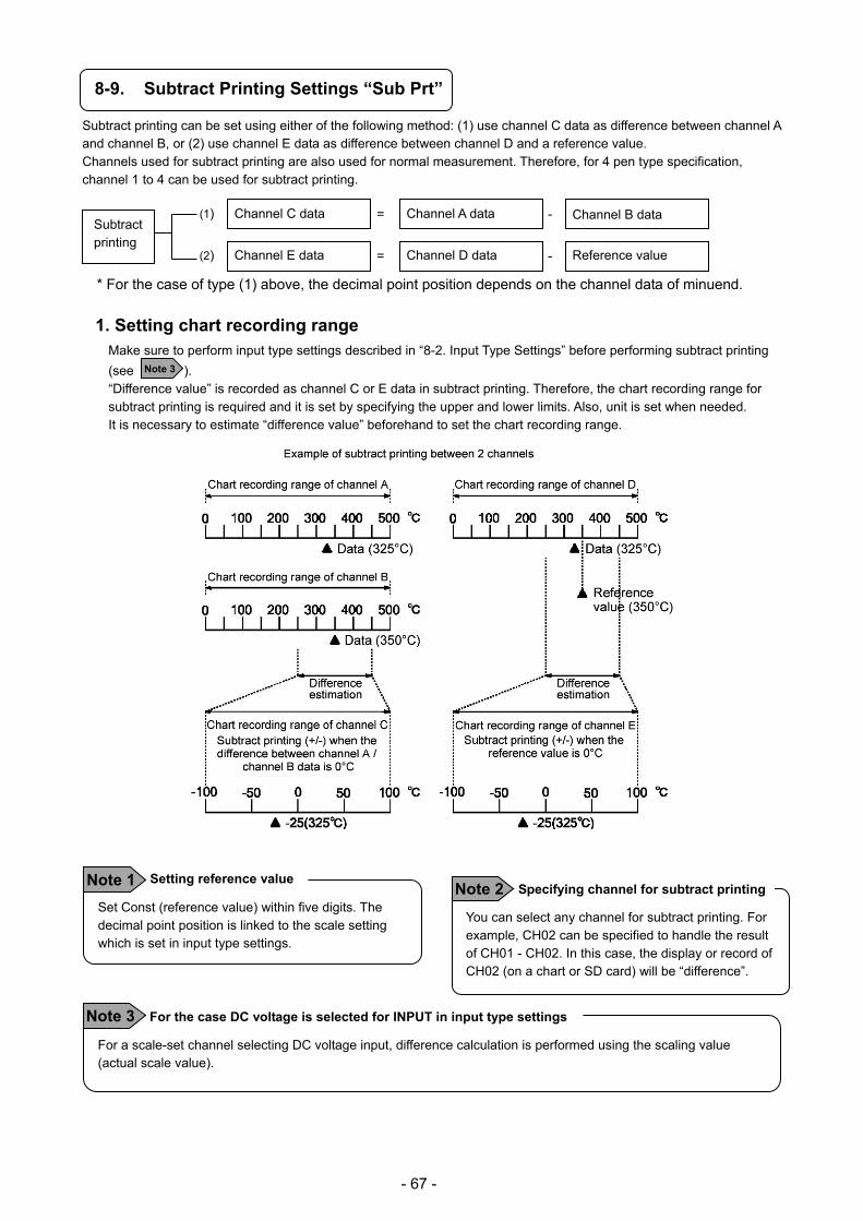
- 67 -
8-9. Subtract Printing Settings “Sub Prt”
Subtract printing can be set using either of the following method: (1) use channel C data as difference between channel A and channel B, or (2) use channel E data as difference between channel D and a reference value. Channels used for subtract printing are also used for normal measurement. Therefore, for 4 pen type specification, channel 1 to 4 can be used for subtract printing.
* For the case of type (1) above, the decimal point position depends on the channel data of minuend.
1. Setting chart recording range
Make sure to perform input type settings described in “8-2. Input Type Settings” before performing subtract printing
(see ). “Difference value” is recorded as channel C or E data in subtract printing. Therefore, the chart recording range for subtract printing is required and it is set by specifying the upper and lower limits. Also, unit is set when needed. It is necessary to estimate “difference value” beforehand to set the chart recording range.
Note 3
Subtract printing
(1) Channel C data
(2) Channel E data
Channel A data Channel B data
Channel D data Reference value
=
=
-
-
Set Const (reference value) within five digits. The decimal point position is linked to the scale setting which is set in input type settings.
Setting reference value Note 1 You can select any channel for subtract printing. For example, CH02 can be specified to handle the result of CH01 - CH02. In this case, the display or record of CH02 (on a chart or SD card) will be “difference”.
Specifying channel for subtract printingNote 2
For a scale-set channel selecting DC voltage input, difference calculation is performed using the scaling value (actual scale value).
For the case DC voltage is selected for INPUT in input type settings Note 3
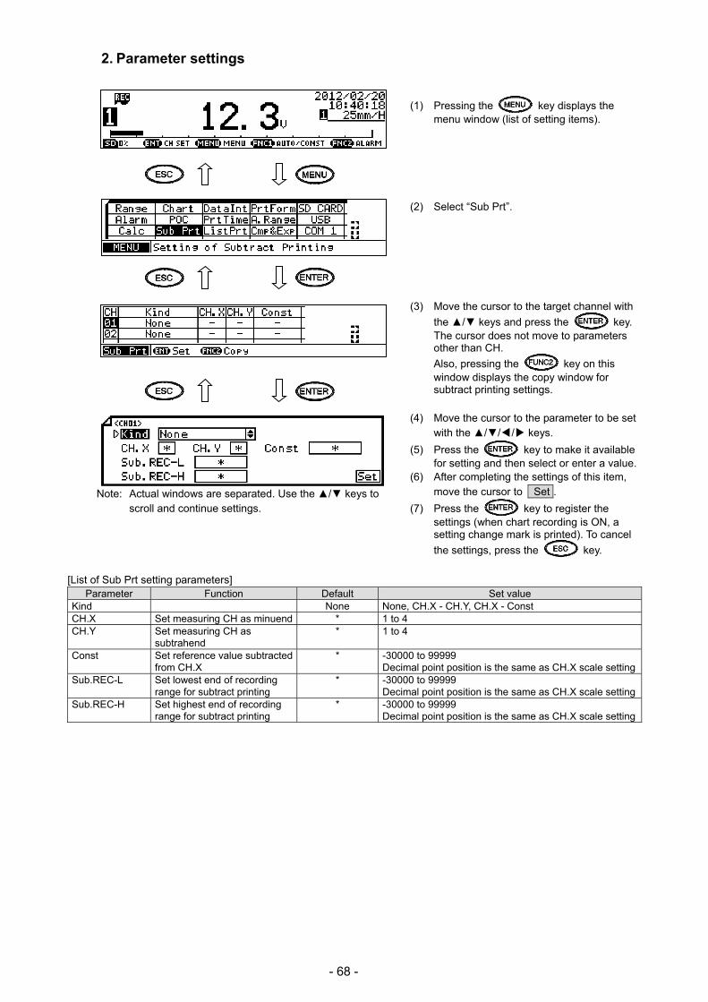
- 68 -
2. Parameter settings
(1) Pressing the key displays the menu window (list of setting items).
(2) Select “Sub Prt”. (3) Move the cursor to the target channel with
the / keys and press the key. The cursor does not move to parameters other than CH.
Also, pressing the key on this window displays the copy window for subtract printing settings.
(4) Move the cursor to the parameter to be set
with the /// keys.
(5) Press the key to make it available for setting and then select or enter a value.
(6) After completing the settings of this item, move the cursor to Set .
(7) Press the key to register the settings (when chart recording is ON, a setting change mark is printed). To cancel
the settings, press the key.
[List of Sub Prt setting parameters] Parameter Function Default Set value
Kind None None, CH.X - CH.Y, CH.X - Const CH.X Set measuring CH as minuend * 1 to 4 CH.Y Set measuring CH as
subtrahend * 1 to 4
Const Set reference value subtracted from CH.X
* -30000 to 99999 Decimal point position is the same as CH.X scale setting
Sub.REC-L Set lowest end of recording range for subtract printing
* -30000 to 99999 Decimal point position is the same as CH.X scale setting
Sub.REC-H Set highest end of recording range for subtract printing
* -30000 to 99999 Decimal point position is the same as CH.X scale setting
Note: Actual windows are separated. Use the / keys to scroll and continue settings.

- 69 -
8-10. Periodic (Data Interval) Data Printing Settings “DataInt”
In addition to the trace printing on a chart, measured data of each channel can be printed numerically. Measured data can be recorded or printed digitally at desired intervals. Select ON/OFF to enable or disable digital recording/printing for each channel (DIGI.REC) in input type settings described in “8-2. Input Type Settings”.
(1) Pressing the key displays the menu window (list of setting items).
(2) Select “DataInt”. (3) Move the cursor to the parameter to be set
with the // / keys.
(4) Press the key to make it available for setting and then enter a value.
(5) After completing the setting of this item, move the cursor to Set .
(6) Press the key to register the settings (when chart recording is ON, a setting change mark is printed). To cancel
the settings, press the key. [List of DataInt setting parameters]
Parameter Function Default Set value StartTime Set start time of periodic data printing
(When a set time is before the current time, periodic data printing is executed next day.)
00 : 00 00 : 00 to 23 : 59
Interval Set interval between printings of numeric measured data (every 24 hours 59 minutes and 1 minute at maximum)
00 : 00 00: 00 to 24 : 59
The shortest interval depends on the chart speed and the number of digital recording/printing channels. If a set interval is inappropriate for the specified chart speed, printing will be executed with a timing of the minimum integral multiple of the interval.
Interval [M] ≥ Note: Interval less than 5min cannot be set.
*1: The lowest speed of three speeds is used.
*2: Differs depending on the chart speed and the number of digital recording/printing channels.
Chart speed 1CH 2CH 3CH 4CH 99mm/H or less 1 row 2 row
100mm/H or more 1 row 2 row 3 row 4 row
Note: This differs from the number of skipped channels.
Calculating the shortest interval Reference
180 x printing lines *2 Chart speed [mm/H] *1

- 70 -
8-11. Periodic (Specified Time) Data Printing Settings “PrtTime”
When the interval described in “8-11. Periodic (Data Interval) Data Printing Settings” is set to “00 : 00”, printing at specified time becomes effective. Time can be specified for up to 24 points and it can be set to ON/OFF individually.
(1) Pressing the key displays the menu window (list of setting items).
(2) Select “PrtTime”. (3) Move the cursor to the target No. with the
/ keys and press the key. The cursor does not move to parameters other than No.
Pressing the key on this window turns ON/OFF printing at specified time.
Also, pressing the key displays the copy window for specified time data printing settings.
(4) Move the cursor to the parameter to be set
with the /// keys.
(5) Press the key to make it available for setting and then enter a value.
(6) After completing the setting of this item, move the cursor to Set .
(7) Press the key to register the setting (when chart recording is ON, a setting change mark is printed). To cancel
the setting, press the key.
[PrtTime setting parameter] Parameter Function Default Set value
PrintTime Set at what time measured data is printed numerically
- - (Not used), 00 : 00 to 23 : 59
When [Print Time] is set to “-“, the setting of the relevant No. of specified time will be disabled.
ON/OFF setting for each print time No. Reference

- 71 -
8-12. List Printing Settings “ListPrt”
List printing is used to check the set contents. Contents to be printed depend on the list number.
(1) Pressing the key displays the menu window (list of setting items).
(2) Select “ListPrt”.
(3) Press the key to make it available for setting and then select the list number. Contents to be printed will be shown on the right.
(4) Move the cursor to Print .
(5) Pressing the key moves cartridge pen to the end of the left side and the chart paper forwards slightly then starts list
printing. Press the key to cancel. Printed contents by List No.] List No. Printed contents
1 Date, Time, CH.Info (channel settings), Rec.Info (recording settings), ALM.Info (alarm settings) 2 Additional Setting, Option Setting Time 3 Date, Time, CH.Info (channel settings), Rec.Info (recording settings),
ALM.Info (alarm settings), Additional Setting, Option Setting Time
To stop list printing, turn the recording status OFF and then ON again. List printing stops when the currently printing line is finished. When list printing is stopped, it cannot be resumed, so you need to set list printing again to perform it.
Stopping list printing Note 2 List printing is available only when recording is ON.
Inexecutable case Note 1
Example of list printing
Trace printing by cartridge pen is not executed. Other
operations are executed continuously without
interruption. During list printing, setting change is not
available. However, setting confirmation is available.
Operation at printing in process Note 3

- 72 -
8-13. Message Printing 1 Settings “MsgPrt1”
A message consisting of 15 characters at maximum can be
printed and up to 20 types of message can be registered. It is
also possible to print a registered message in conjunction with
the calendar timer or remote contacts (calendar timer and
remote contacts should be set separately).
(1) Pressing the key displays the menu window (list of setting items).
(2) Select “MsgPrt1”.
(3) Move the cursor to the target message No.
with the / keys and press the key. The cursor does not move to parameters other than No. Also, pressing
the key on this window prints the message of selected No. When “*** Start
printing? ***” is displayed, press the
key. Pressing the key displays the copy window for message settings.
(4) Move the cursor to the parameter to be set
with the /// keys.
(5) Press the key to make it available for setting and then select or enter a value.
(6) After completing the settings of this item, move the cursor to Set .
(7) Press the key to register the settings (when chart recording is ON, a setting change mark is printed). To cancel
the settings, press the key.
[List of MsgPrt1 setting parameters] Parameter Function Default Set value
Message Set a string consisting of up to 15 characters to be printed
Not set
Example of message printing
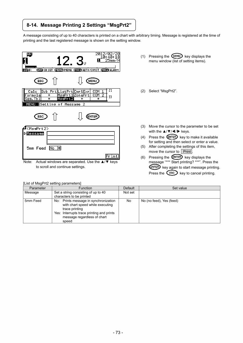
- 73 -
8-14. Message Printing 2 Settings “MsgPrt2”
A message consisting of up to 40 characters is printed on a chart with arbitrary timing. Message is registered at the time of printing and the last registered message is shown on the setting window.
(1) Pressing the key displays the menu window (list of setting items).
(2) Select “MsgPrt2”. (3) Move the cursor to the parameter to be set
with the /// keys.
(4) Press the key to make it available for setting and then select or enter a value.
(5) After completing the settings of this item, move the cursor to Print .
(6) Pressing the key displays the message “*** Start printing? ***”. Press the
key again to start message printing.
Press the key to cancel printing.
[List of MsgPrt2 setting parameters] Parameter Function Default Set value
Message Set a string consisting of up to 40 characters to be printed
Not set
5mm Feed No: Prints message in synchronization with chart speed while executing trace printing
Yes: Interrupts trace printing and prints message regardless of chart speed
No No (no feed), Yes (feed)
Note: Actual windows are separated. Use the / keys to scroll and continue settings.

- 74 -
8-15. Recording Format Settings “PrtForm”
Set the format for trace printing depending on the intended use. This function is provided to select the format used for trace printing. Input range and its accuracy are determined by the settings made in “8-2. Input Type Settings”. The recording format cannot be set for each individual channel. Select one from the following options which is shared by all channels. However, when selecting the automatic range-shift or compressed/expanded printing, whether or not to use the function can be specified for each channel. A channel specified not to use the function will use the standard format.
Automatic range-shift ····················· Recording range is shifted automatically depending on the input range. Compressed/expanded printing ······· Chart recording area can be partially shrunk or expanded. Zone printing ······························· Chart recording area can be divided into two areas at maximum.
(1) Pressing the key displays the menu window (list of setting items).
(2) Select “PrtForm”.
(3) Press the key to make it available for setting and then select a value.
(4) After completing the setting of this item, move the cursor to Set .
(5) Press the key to register the setting (when chart recording is ON, a setting change mark is printed). To cancel
the setting, press the key.
[PrtForm setting parameter] Parameter Function Default Set value
Printing Format Select recording format Standard Standard, Auto Range Normal (automatic range-shift normal), Auto Range Overlap (automatic range-shift overlap), Comp.&Exp.Print (compressed/expanded printing), Zone Print (parallel scale)
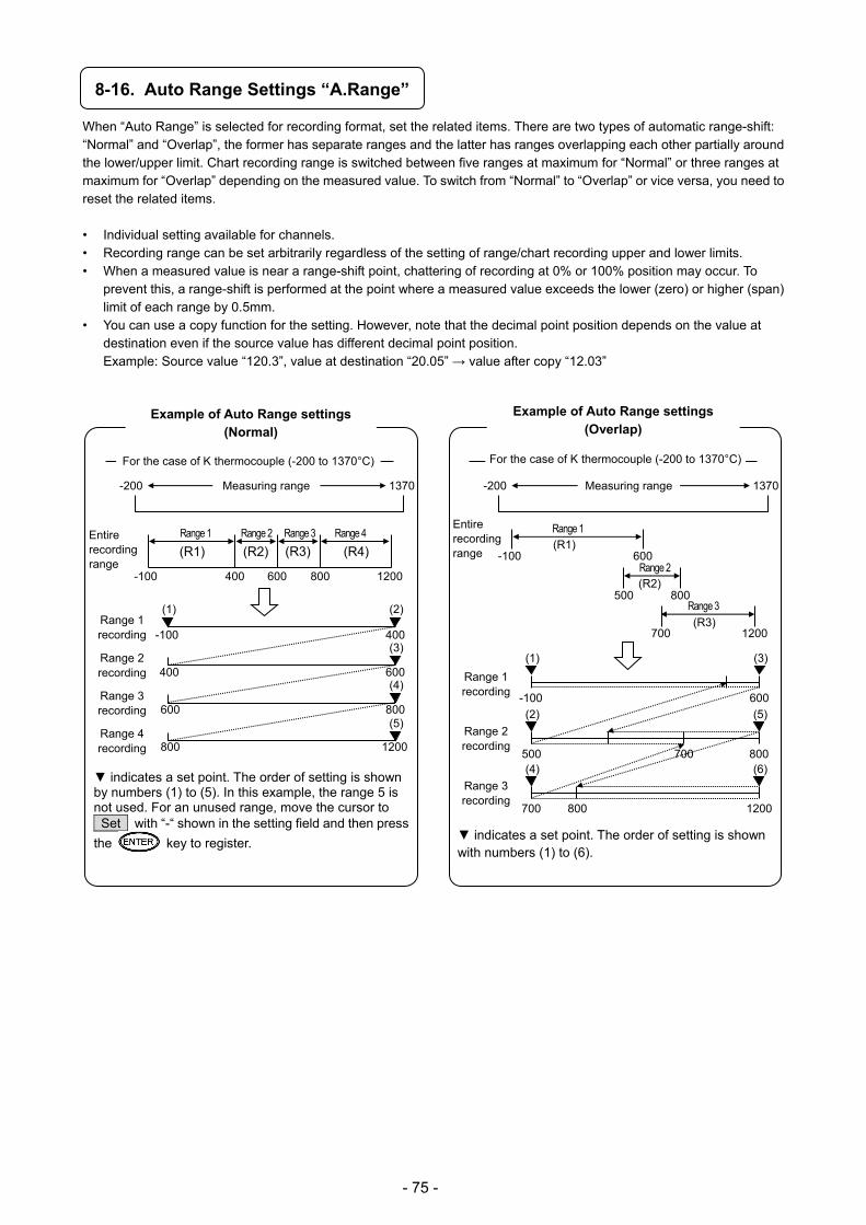
- 75 -
8-16. Auto Range Settings “A.Range”
When “Auto Range” is selected for recording format, set the related items. There are two types of automatic range-shift: “Normal” and “Overlap”, the former has separate ranges and the latter has ranges overlapping each other partially around the lower/upper limit. Chart recording range is switched between five ranges at maximum for “Normal” or three ranges at maximum for “Overlap” depending on the measured value. To switch from “Normal” to “Overlap” or vice versa, you need to reset the related items.
• Individual setting available for channels. • Recording range can be set arbitrarily regardless of the setting of range/chart recording upper and lower limits. • When a measured value is near a range-shift point, chattering of recording at 0% or 100% position may occur. To
prevent this, a range-shift is performed at the point where a measured value exceeds the lower (zero) or higher (span) limit of each range by 0.5mm.
• You can use a copy function for the setting. However, note that the decimal point position depends on the value at destination even if the source value has different decimal point position. Example: Source value “120.3”, value at destination “20.05” → value after copy “12.03”
indicates a set point. The order of setting is shown by numbers (1) to (5). In this example, the range 5 is not used. For an unused range, move the cursor to Set with “-“ shown in the setting field and then press
the key to register.
-200 1370
Entire recording range
(R1)
Range 1 Range 2 Range 3 Range 4
-100 400 600 800 1200
(R2) (R3) (R4)
Measuring range
(1) (2)
-100 400
400 600
600 800
800 1200
Range 1 recording
Range 2 recording
Range 3 recording
Range 4 recording
(3)
(4)
(5)
Example of Auto Range settings (Normal)
For the case of K thermocouple (-200 to 1370°C)
indicates a set point. The order of setting is shown with numbers (1) to (6).
Example of Auto Range settings (Overlap)
-200 1370
Entire recording range
(R1) Range 1
-100 600
Measuring range
Range 2
500 800 (R2)
Range 3
700 1200(R3)
(1)
-100 600
Range 1 recording
500 800
Range 2 recording
1200
Range 3 recording
700
700
800
(2)
(3)
(4)
(5)
(6)
For the case of K thermocouple (-200 to 1370°C)

- 76 -
* Make sure that the recording format is set to “Auto Range (automatic range-shift)” and then perform the following settings.
(1) Pressing the key displays the menu window (list of setting items).
(2) Select “A.Range”.
(3) Move the cursor to the target channel with
the / keys and press the key. The cursor does not move to parameters other than CH.
Also, pressing the key on this window displays the copy window for Auto Range settings.
(4) Press the key while the cursor is on “Auto Range ON/OFF” and select ON.
(5) Move the cursor to the parameter to be set with the /// keys.
(6) Press the key to make it available for setting and then select or enter a value.
If the set value of 1st Max is equal to or less
than 1st Min value, it will not be accepted.
The set value should be: 1st Min < 1st Max
< 2nd Max < 3rd Max …
(7) After completing the settings of this item,
move the cursor to Set .
(8) Press the key to register the settings (when chart recording is ON, a setting change mark is printed). To cancel
the settings, press the key.
[List of A.Range setting parameters] Upper section: Auto Range (Normal), Lower section: Auto Range (Overlap) Parameter Function Default Set value
Auto Range ON/OFF OFF ON (enabled), OFF (disabled) 1st Min Set lowest end of 1st range
* - (None), -30000 to 99999 Decimal point position is the same as CH scale setting
1st Min Set lowest end of 1st range
1st Max Set highest end of 1st range *
- (None), -30000 to 99999 Decimal point position is the same as CH scale setting
2nd Min Set lowest end of 2nd range
2nd Max Set highest end of 2nd range*
- (None), -30000 to 99999 Decimal point position is the same as CH scale setting
1st Max Set highest end of 1st range
3rd Max Set highest end of 3rd range *
- (None), -30000 to 99999 Decimal point position is the same as CH scale setting
3rdMin Set lowest end of 3rd range
4th Max Set highest end of 4th range *
- (None), -30000 to 99999 Decimal point position is the same as CH scale setting
2nd Max Set highest end of 2nd range
5th Max Set highest end of 5th range *
- (None), -30000 to 99999 Decimal point position is the same as CH scale setting
3rd Max Set highest end of 3rd range
Note: Actual windows are separated. Use the / keys to scroll and continue settings.
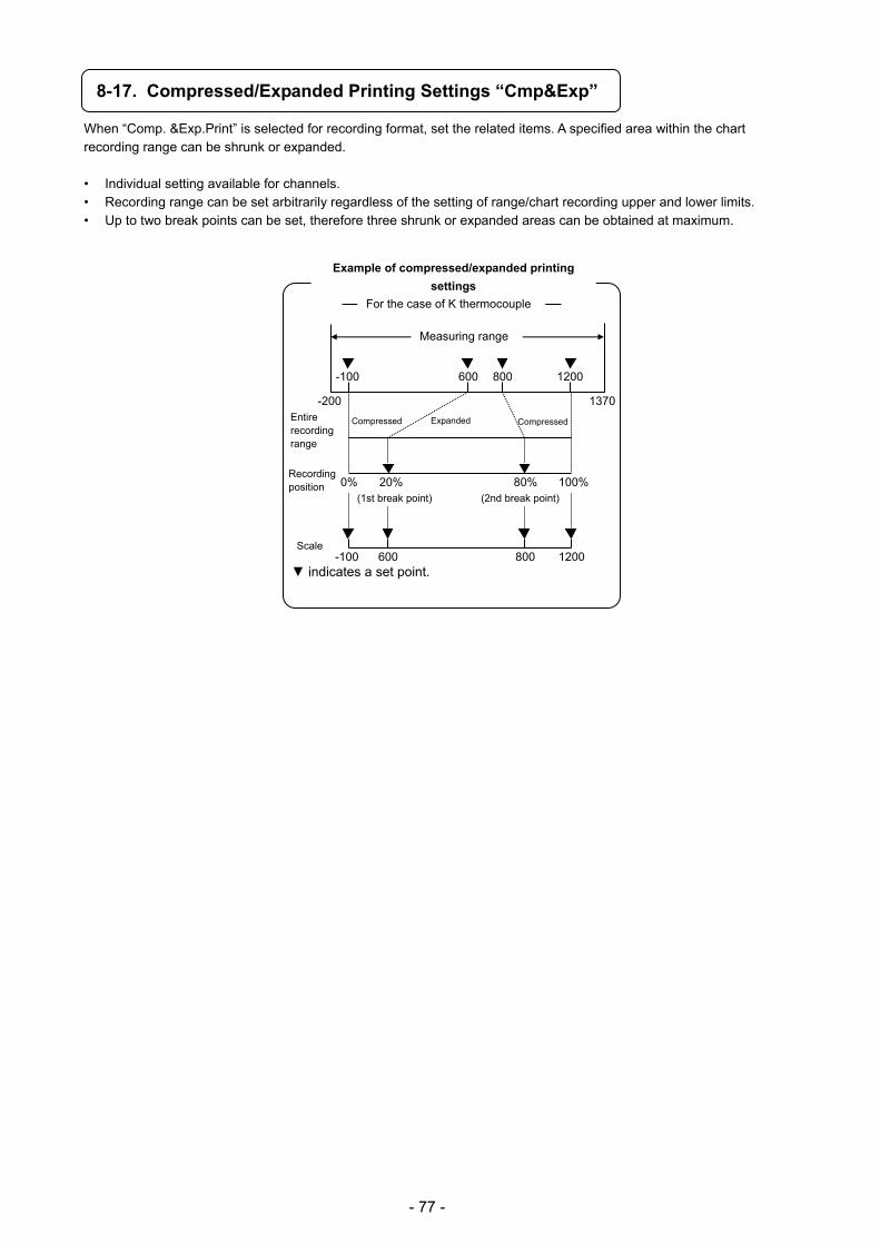
- 77 -
8-17. Compressed/Expanded Printing Settings “Cmp&Exp”
When “Comp. &Exp.Print” is selected for recording format, set the related items. A specified area within the chart recording range can be shrunk or expanded.
• Individual setting available for channels. • Recording range can be set arbitrarily regardless of the setting of range/chart recording upper and lower limits. • Up to two break points can be set, therefore three shrunk or expanded areas can be obtained at maximum.
indicates a set point.
Example of compressed/expanded printing
settings
Entire recording range
Scale
(1st break point) (2nd break point)
Compressed Expanded Compressed
Recording position
-200 1370
-100 600 800 1200
0% 100%20% 80%
-100 600 800 1200
For the case of K thermocouple
Measuring range
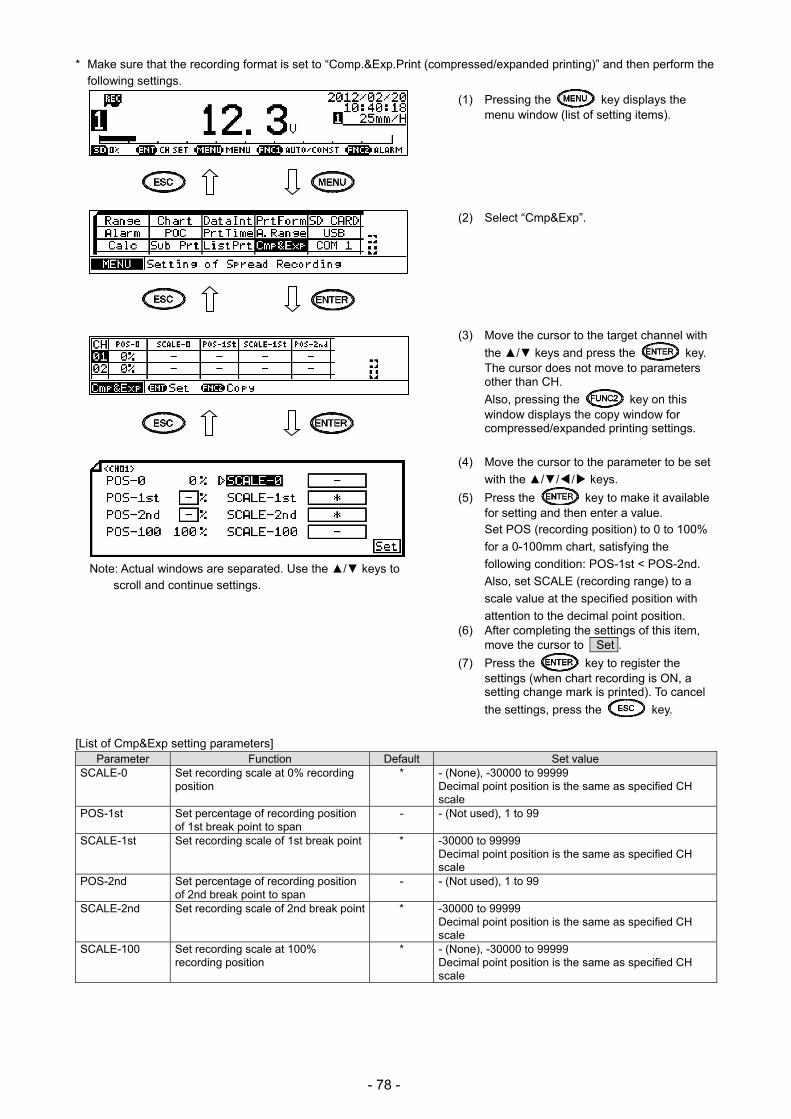
- 78 -
* Make sure that the recording format is set to “Comp.&Exp.Print (compressed/expanded printing)” and then perform the following settings.
(1) Pressing the key displays the menu window (list of setting items).
(2) Select “Cmp&Exp”.
(3) Move the cursor to the target channel with
the / keys and press the key. The cursor does not move to parameters other than CH.
Also, pressing the key on this window displays the copy window for compressed/expanded printing settings.
(4) Move the cursor to the parameter to be set
with the /// keys.
(5) Press the key to make it available for setting and then enter a value.
Set POS (recording position) to 0 to 100%
for a 0-100mm chart, satisfying the
following condition: POS-1st < POS-2nd.
Also, set SCALE (recording range) to a
scale value at the specified position with
attention to the decimal point position. (6) After completing the settings of this item,
move the cursor to Set .
(7) Press the key to register the settings (when chart recording is ON, a setting change mark is printed). To cancel
the settings, press the key.
[List of Cmp&Exp setting parameters] Parameter Function Default Set value
SCALE-0 Set recording scale at 0% recording position
* - (None), -30000 to 99999 Decimal point position is the same as specified CH scale
POS-1st Set percentage of recording position of 1st break point to span
- - (Not used), 1 to 99
SCALE-1st Set recording scale of 1st break point * -30000 to 99999 Decimal point position is the same as specified CH scale
POS-2nd Set percentage of recording position of 2nd break point to span
- - (Not used), 1 to 99
SCALE-2nd Set recording scale of 2nd break point * -30000 to 99999 Decimal point position is the same as specified CH scale
SCALE-100 Set recording scale at 100% recording position
* - (None), -30000 to 99999 Decimal point position is the same as specified CH scale
Note: Actual windows are separated. Use the / keys to scroll and continue settings.
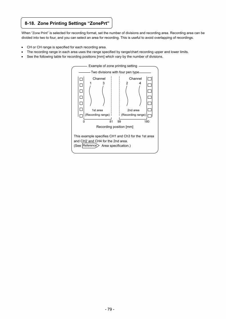
- 79 -
8-18. Zone Printing Settings “ZonePrt”
When “Zone Print” is selected for recording format, set the number of divisions and recording area. Recording area can be divided into two to four, and you can select an area for recording. This is useful to avoid overlapping of recordings.
CH or CH range is specified for each recording area. The recording range in each area uses the range specified by range/chart recording upper and lower limits. See the following table for recording positions [mm] which vary by the number of divisions.
Recording position [mm]
This example specifies CH1 and Ch3 for the 1st area
and CH2 and CH4 for the 2nd area. (See Area specification.)
Example of zone printing setting
Channel 1 3
Channel 2 4
1st area
(Recording range)
2nd area
(Recording range)
0 81 99 180
Reference
Two divisions with four pen type

- 80 -
* Make sure that the recording format is set to “Zone Print (zone printing)” and then perform the following settings.
(1) Pressing the key displays the menu window (list of setting items).
(2) Select “ZonePrt”.
(3) Press the key.
(4) Move the cursor to the parameter to be set
with the /// keys.
(5) Press the key to make it available for setting and then select or enter a value.
(6) After completing the settings of this item, move the cursor to Set .
(7) Press the key to register the settings (when chart recording is ON, a setting change mark is printed). To cancel
the settings, press the key.
[List of Zoneprt setting parameters] Parameter Function Default Set value
Zone Set number of divisions for zone printing
2
Type Area specification format Selected from options
CH.X CH.X, CH.X/CH.Y, CH.X - CH.Y, CH.X/CH.Y/CH.Z, CH.X - CH.Y/CH.Z, CH.X/CH.Y - CH.Z
CH.X - - (Not used), 1 to 4 CH.Y * - (Not used), 1 to 4 CH.Z * - (Not used), 1 to 4
Note: Actual windows are separated. Use the / keys to scroll and continue settings. The number of areas increases as you select a greater number for division (Zone), resulting in the need of setting more parameters.
(CH.X) ········································· Record CH.X to the specified area. (CH.X)/(CH.Y) ······························· Record CH.X and CH.Y to the specified area. (CH.X) - (CH.Y) ····························· Record CH.X - CH.Y to the specified area. (CH.X)/(CH.Y)/(CH.Z) ····················· Record CH.X, CH.Y and CH.Z to the specified area. (CH.X) - (CH.Y)/(CH.Z) ···················· Record CH.X - CH.Y and CH.Z to the specified area. (CH.X)/(CH.Y) - (CH.Z) ···················· Record CH.X and CH.Y - CH.Z to the specified area.
Area specification (Type)
Reference
A channel not selected for any area will be skipped. An error occurs when the same channel is set for multiple areas.
CH selection
Note

- 81 -
8-19. SD Card “SD CARD”
Measured data can be stored on an SD card at arbitrarily specified time and interval (0.1sec at maximum). Also, measurement/recording conditions including range, scale and chart speed can be stored on an SD card, and the stored data can be used to set up the instrument when needed. SD card is an accessory part (sold separately). Use one provided by Azbil.
1. Attaching/removing SD card Insert an SD card with the label facing down into the insertion slot located at the front section of internal unit. When an SD card is inserted, the “CARD” status LED in the operation/set keys section flashes in green, and an error check is performed automatically. When the card is successfully recognized, the status LED stops flashing and stays on. To remove an SD card, you must take the steps for proper removal. (See “8-19.7. Removing SD card”.) SD card can be removed from the slot by pressing it inward and releasing it with you finger.
2. Operation There are three types of SD card operation menu: Recording data-Saving (settings related to measured data save), Setting Parameter (saving/loading setting parameters) and SD Card (removal/maintenance).
When a recording to SD card starts, the status on the display turns from “SD” to “R”.
3. Handling Observe the following warnings and cautions to use SD card safely and prevent loss or damage to your property.
Never disassemble or modify SD card. It may result in fire, electric shock or malfunction.
Do not use SD card in a location where it may get wet or condensation occurs. The internal circuit of SD card may be damaged in such a location.
Do not handle (attach/remove) SD card near small children to avoid accidental ingestion or other dangerous situations.
Do not store SD card in a location exposed to direct sunlight, high temperature, high humidity or too much dust. It may degrade the quality by distortion or warping.
Do not apply strong impact by dropping, hitting or bending it. It may distort and damage SD card.
Store SD card with care not to allow dust to enter the connector. To protect the internal circuit from static electricity, do not touch the connector
(terminal) with your hand or a metal object.
! Warning
! Caution
Do not remove SD card or turn off the power while the “CARD” status LED is lit. SD card has been formatted to FAT prior to shipment (SD card is an optional device). Execution of format deletes all the stored data. Check the data before starting format. While SD card is being accessed, never remove the SD card or turn off the unit connecting the SD
card. Otherwise, the data of SD card may be destroyed or the unit itself may be damaged. Please note that Azbil holds no responsibilities for losses resulting from damage or data loss of SD
card. Use SD card with 2GB or less memory and format to FAT16. Use Azbil’s SD card sold separately.
About SD card Note
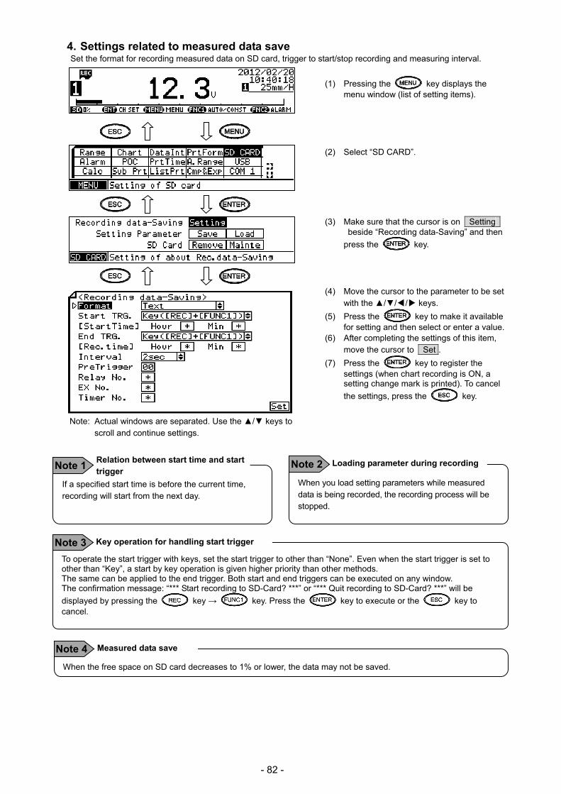
- 82 -
4. Settings related to measured data save Set the format for recording measured data on SD card, trigger to start/stop recording and measuring interval.
(1) Pressing the key displays the menu window (list of setting items).
(2) Select “SD CARD”. (3) Make sure that the cursor is on Setting
beside “Recording data-Saving” and then
press the key.
(4) Move the cursor to the parameter to be set with the /// keys.
(5) Press the key to make it available for setting and then select or enter a value.
(6) After completing the settings of this item, move the cursor to Set .
(7) Press the key to register the settings (when chart recording is ON, a setting change mark is printed). To cancel
the settings, press the key.
To operate the start trigger with keys, set the start trigger to other than “None”. Even when the start trigger is set to other than “Key”, a start by key operation is given higher priority than other methods. The same can be applied to the end trigger. Both start and end triggers can be executed on any window. The confirmation message: “*** Start recording to SD-Card? ***” or “*** Quit recording to SD-Card? ***” will be
displayed by pressing the key → key. Press the key to execute or the key to cancel.
Key operation for handling start trigger Note 3
Note: Actual windows are separated. Use the / keys to scroll and continue settings.
If a specified start time is before the current time, recording will start from the next day.
Relation between start time and start trigger
Note 1 When you load setting parameters while measured data is being recorded, the recording process will be stopped.
Loading parameter during recording Note 2
When the free space on SD card decreases to 1% or lower, the data may not be saved.
Measured data save Note 4
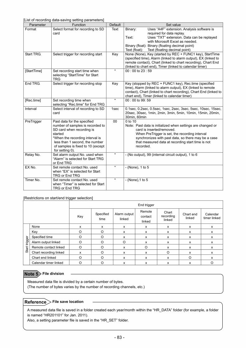
- 83 -
[List of recording data-saving setting parameters] Parameter Function Default Set value
Format Select format for recording to SD card
Text Binary: Uses “A4F” extension. Analysis software is required for data replay.
Text: Uses “TXT” extension. Data can be replayed with Microsoft Excel as needed.
Binary (float): Binary (floating decimal point) Text (float): Text (floating decimal point)
Start TRG. Select trigger for recording start Key None (None), Key (started by REC + FUNC1 key), StartTime (specified time), Alarm (linked to alarm output), EX (linked to remote contact), Chart (linked to chart recording), Chart End (linked to chart end), Timer (linked to calendar timer)
[StartTime] Set recording start time when selecting “StartTime” for Start TRG
* 00 : 00 to 23 : 59
End TRG. Select trigger for recording stop Key Key (stopped by REC + FUNC1 key), Rec.time (specified time), Alarm (linked to alarm output), EX (linked to remote contact), Chart (linked to chart recording), Chart End (linked to chart end), Timer (linked to calendar timer)
[Rec.time] Set recording time when selecting “Rec.time” for End TRG
* 00 : 00 to 99: 59
Interval Select interval of recording to SD card
1sec
0.1sec, 0.2sec, 0.5sec, 1sec, 2sec, 3sec, 5sec, 10sec, 15sec, 20sec, 30sec, 1min, 2min, 3min, 5min, 10min, 15min, 20min, 30min, 60min
PreTrigger Past data for the specified number of samples is recorded to SD card when recording is started *When the recording interval is less than 1 second, the number of samples is fixed to 10 (except for setting 0).
00 0 to 10 Note: Past data is initialized when settings are changed or
card is inserted/removed. When PreTrigger is set, the recording interval synchronizes with past data, so there may be a case that measured data at recording start time is not recorded.
Relay No. Set alarm output No. used when “Alarm” is selected for Start TRG or End TRG
* - (No output), 99 (internal circuit output), 1 to 6
EX No. Set remote contact No. used when “EX” is selected for Start TRG or End TRG
* - (None), 1 to 5
Timer No. Set remote contact No. used when “Timer” is selected for Start TRG or End TRG
* - (None),1 to 5
[Restrictions on start/end trigger selection]
End trigger
Key Specified
time
Alarm output
linked
Remote
contact
linked
Chart recording
linked
Chart end linked
Calendar timer linked
Sta
rt tr
igge
r
None x x x x x x x
Key O O x x x x x
Specified time O O x x x x x
Alarm output linked O O O x x x x
Remote contact linked O O x O x x x
Chart recording linked x O x x O x x
Chart end linked O O x x x O x
Calendar timer linked O O x x x x O
Measured data file is divided by a certain number of bytes. (The number of bytes varies by the number of recording channels, etc.)
File division Note 5
A measured data file is saved in a folder created each year/month within the “HR_DATA” folder (for example, a folder is named “HR201101” for Jan. 2011). Also, a setting parameter file is saved in the “HR_SET” folder.
File save location Reference

- 84 -
5. Saving setting parameters The setting data of the unit can be saved to an SD card.
(1) Select “SD CARD” from the menu window (list of setting items).
(2) Move the cursor to Save beside “Setting
Parameter” and press the key.
(3) Select New to add a file. To overwrite a file, select the file No. to be overwritten.
Also, pressing the key on this window can remove the data of specified file No. from SD card. When “*** Delete?
***” is displayed, press the key again to remove the data.
(4) Press the key to make it available for setting and then enter a file name. Enter single-byte, upper-case alphanumeric characters up to eight digits.
(5) After completing the settings of this item, move the cursor to Set .
(6) Press the key. When “*** Start
Saving? ***” is displayed, press the key to start saving setting parameters to SD
card. To cancel saving, press the key.
You cannot specify the same name for files even if they have different numbers.
Setting file name Note 1 The maximum number of setting parameter files which can be saved to a single SD card is 10.
Number of files saved Note 2
On the setting file list window, files are displayed in the chronological order with the most recent updated file listed first.
File display order Reference 1 When a file name is registered on the setting parameter registration window, the update date will be reflected automatically.
Update date display Reference 2
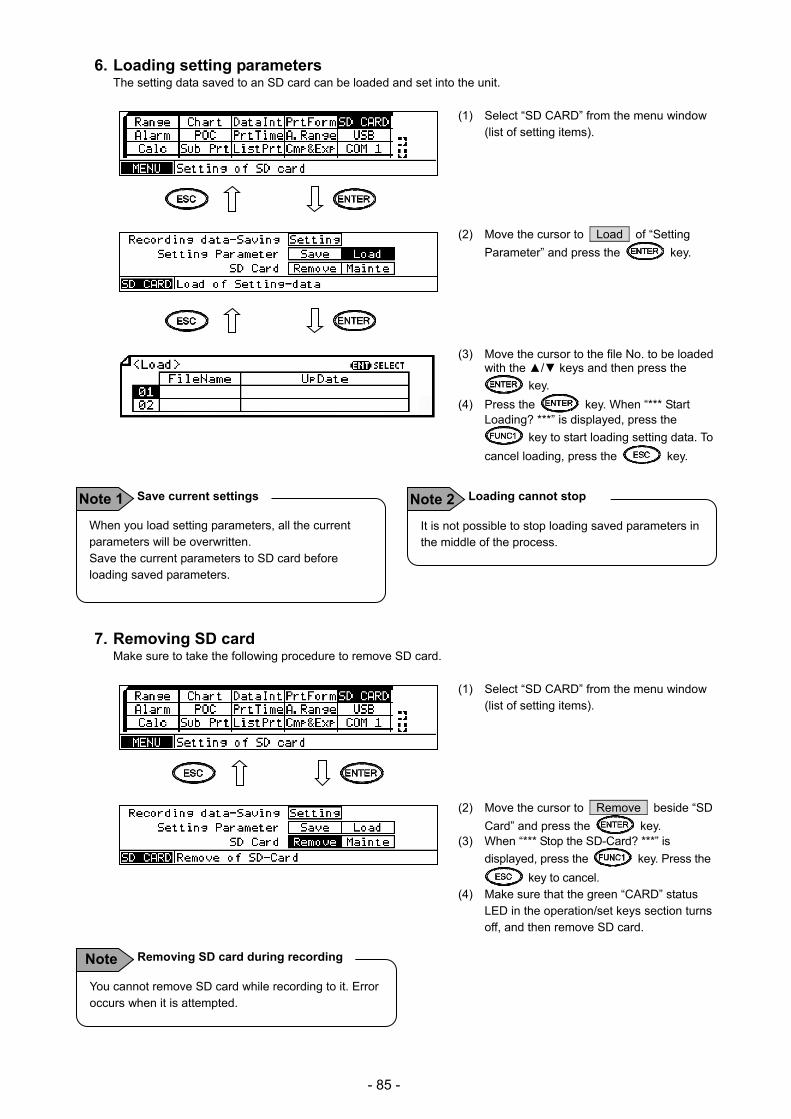
- 85 -
6. Loading setting parameters The setting data saved to an SD card can be loaded and set into the unit.
(1) Select “SD CARD” from the menu window (list of setting items).
(2) Move the cursor to Load of “Setting
Parameter” and press the key.
(3) Move the cursor to the file No. to be loaded
with the / keys and then press the
key.
(4) Press the key. When “*** Start Loading? ***” is displayed, press the
key to start loading setting data. To
cancel loading, press the key.
7. Removing SD card Make sure to take the following procedure to remove SD card.
(1) Select “SD CARD” from the menu window (list of setting items).
(2) Move the cursor to Remove beside “SD
Card” and press the key. (3) When “*** Stop the SD-Card? ***” is
displayed, press the key. Press the
key to cancel. (4) Make sure that the green “CARD” status
LED in the operation/set keys section turns off, and then remove SD card.
When you load setting parameters, all the current parameters will be overwritten. Save the current parameters to SD card before loading saved parameters.
Save current settings Note 1 It is not possible to stop loading saved parameters in the middle of the process.
Loading cannot stop Note 2
You cannot remove SD card while recording to it. Error occurs when it is attempted.
Removing SD card during recording Note
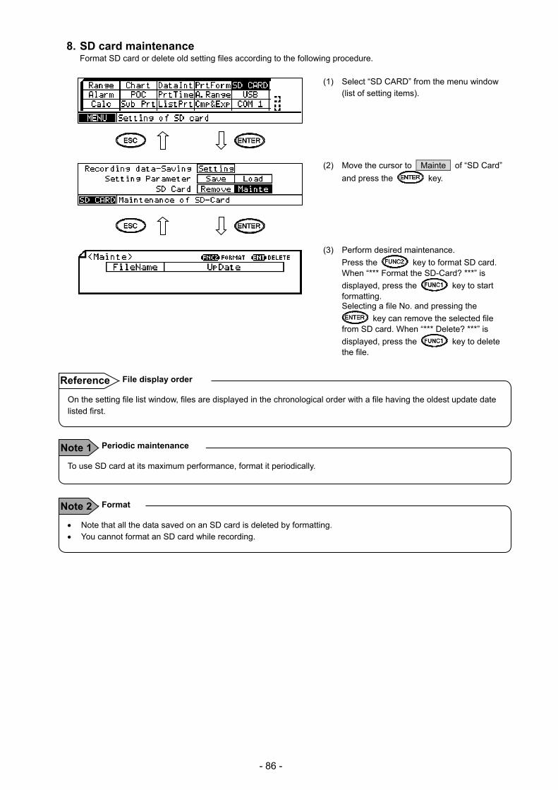
- 86 -
8. SD card maintenance Format SD card or delete old setting files according to the following procedure.
(1) Select “SD CARD” from the menu window (list of setting items).
(2) Move the cursor to Mainte of “SD Card”
and press the key.
(3) Perform desired maintenance.
Press the key to format SD card. When “*** Format the SD-Card? ***” is
displayed, press the key to start formatting. Selecting a file No. and pressing the
key can remove the selected file from SD card. When “*** Delete? ***” is
displayed, press the key to delete the file.
On the setting file list window, files are displayed in the chronological order with a file having the oldest update date listed first.
File display order Reference
To use SD card at its maximum performance, format it periodically.
Periodic maintenance Note 1
Note that all the data saved on an SD card is deleted by formatting. You cannot format an SD card while recording.
Format Note 2
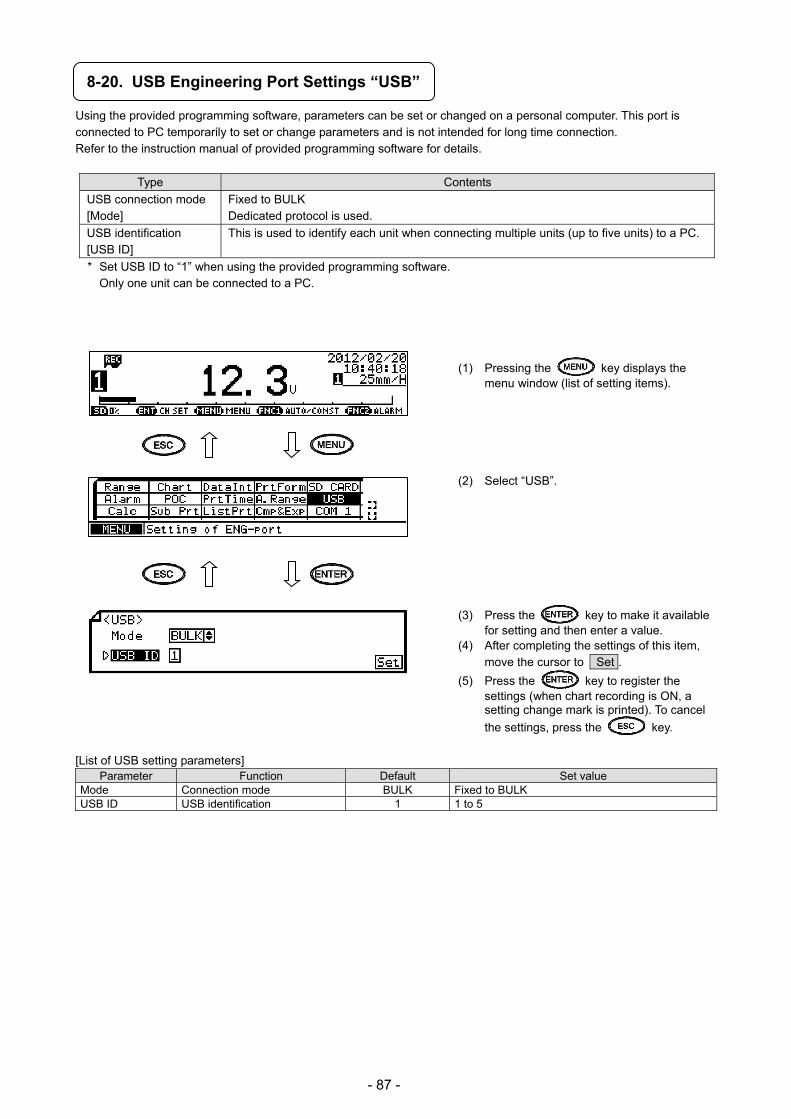
- 87 -
8-20. USB Engineering Port Settings “USB”
Using the provided programming software, parameters can be set or changed on a personal computer. This port is connected to PC temporarily to set or change parameters and is not intended for long time connection. Refer to the instruction manual of provided programming software for details.
Type Contents
USB connection mode [Mode]
Fixed to BULK Dedicated protocol is used.
USB identification [USB ID]
This is used to identify each unit when connecting multiple units (up to five units) to a PC.
* Set USB ID to “1” when using the provided programming software. Only one unit can be connected to a PC.
(1) Pressing the key displays the menu window (list of setting items).
(2) Select “USB”.
(3) Press the key to make it available for setting and then enter a value.
(4) After completing the settings of this item, move the cursor to Set .
(5) Press the key to register the settings (when chart recording is ON, a setting change mark is printed). To cancel
the settings, press the key. [List of USB setting parameters]
Parameter Function Default Set value Mode Connection mode BULK Fixed to BULK USB ID USB identification 1 1 to 5

- 88 -
8-21. Calendar Timer Settings “Timer”
Alarm relay output ON/OFF or message printing can be executed on a date specified arbitrarily. Up to five dates can be set, and alarm relay output ON/OFF or message No. can be specified for each date. Actual printing is executed in the following order: “Date”, “Time”, “Timer No.” and then “Message”.
(1) Pressing the key displays the
menu window (list of setting items). (2) Select “Timer”. (3) Move the cursor to the target calendar timer
No. with the / keys and press the
key. The cursor does not move to parameters other than No.
Also, pressing the key on this window displays the copy window for calendar timer settings.
(4) Move the cursor to the parameter to be set
with the // / keys.
(5) Press the key to make it available for setting and then select or enter a value.
(6) After completing the settings of this item, move the cursor to Set .
(7) Press the key to register the settings (when chart recording is ON, a setting change mark is printed). To cancel
the settings, press the key.
[List of Timer setting parameters] Parameter Function Default Set value
Mode Select timer type None None, ON (specify ON time only) ON & OFF (specify both ON and OFF times)
[Timer ON] Set date and time for alarm output ON or message printing
* Jan 1, 2000 to Dec 31, 2099 00 : 00 to 23 : 59
[Timer OFF] Set date and time for alarm output OFF * Jan 1, 2000 to Dec 31, 2099 00 : 00 to 23 : 59
Relay No. Specify relay No. for timer ON output * - (No output at timer ON), 99 (internal circuit output), 1 to 6
And/Or Select circuit type for timer ON output * And, Or Message No. Specify message No. printed at timer ON * - (Message not printed at timer ON), 1 to 20
Note: Actual windows are separated. Use the / keys to scroll and continue settings.
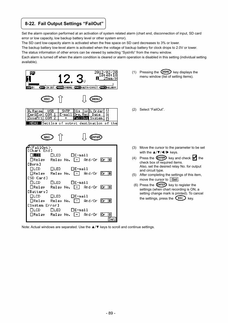
- 89 -
8-22. Fail Output Settings “FailOut”
Set the alarm operation performed at an activation of system related alarm (chart end, disconnection of input, SD card error or low capacity, low backup battery level or other system error). The SD card low-capacity alarm is activated when the free space on SD card decreases to 3% or lower. The backup battery low-level alarm is activated when the voltage of backup battery for clock drops to 2.0V or lower. The status information of other errors can be viewed by selecting “SysInfo” from the menu window. Each alarm is turned off when the alarm condition is cleared or alarm operation is disabled in this setting (individual setting available).
(1) Pressing the key displays the menu window (list of setting items).
(2) Select “FailOut”. (3) Move the cursor to the parameter to be set
with the /// keys.
(4) Press the key and check the check box of required items. Also, set the desired relay No. for output and circuit type.
(5) After completing the settings of this item, move the cursor to Set .
(6) Press the key to register the settings (when chart recording is ON, a setting change mark is printed). To cancel
the settings, press the key.
Note: Actual windows are separated. Use the / keys to scroll and continue settings.
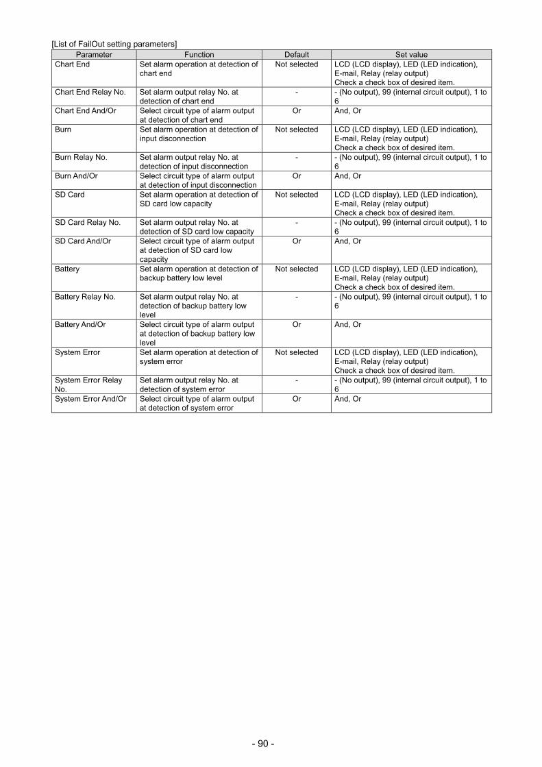
- 90 -
[List of FailOut setting parameters] Parameter Function Default Set value
Chart End Set alarm operation at detection of chart end
Not selected LCD (LCD display), LED (LED indication), E-mail, Relay (relay output) Check a check box of desired item.
Chart End Relay No. Set alarm output relay No. at detection of chart end
- - (No output), 99 (internal circuit output), 1 to 6
Chart End And/Or Select circuit type of alarm output at detection of chart end
Or And, Or
Burn Set alarm operation at detection of input disconnection
Not selected LCD (LCD display), LED (LED indication), E-mail, Relay (relay output) Check a check box of desired item.
Burn Relay No. Set alarm output relay No. at detection of input disconnection
- - (No output), 99 (internal circuit output), 1 to 6
Burn And/Or Select circuit type of alarm output at detection of input disconnection
Or And, Or
SD Card Set alarm operation at detection of SD card low capacity
Not selected LCD (LCD display), LED (LED indication), E-mail, Relay (relay output) Check a check box of desired item.
SD Card Relay No. Set alarm output relay No. at detection of SD card low capacity
- - (No output), 99 (internal circuit output), 1 to 6
SD Card And/Or Select circuit type of alarm output at detection of SD card low capacity
Or And, Or
Battery Set alarm operation at detection of backup battery low level
Not selected LCD (LCD display), LED (LED indication), E-mail, Relay (relay output) Check a check box of desired item.
Battery Relay No. Set alarm output relay No. at detection of backup battery low level
- - (No output), 99 (internal circuit output), 1 to 6
Battery And/Or Select circuit type of alarm output at detection of backup battery low level
Or And, Or
System Error Set alarm operation at detection of system error
Not selected LCD (LCD display), LED (LED indication), E-mail, Relay (relay output) Check a check box of desired item.
System Error Relay No.
Set alarm output relay No. at detection of system error
- - (No output), 99 (internal circuit output), 1 to 6
System Error And/Or Select circuit type of alarm output at detection of system error
Or And, Or

- 91 -
8-23. Display Settings “Display”
The display mode, channel update interval, brightness and chart illumination can be set. When the display backlight and chart illumination are set to “AUTO” in ON/OFF/AUTO setting, the LCD backlight and chart illumination will be turned off when an unused period reaches three minutes. They will be turned on when any key is pressed.
(1) Pressing the key displays the menu window (list of setting items).
(2) Select “Display”. (3) Move the cursor to the parameter to be set
with the // / keys.
(4) Press the key to make it available for setting and then select or enter a value.
(5) After completing the settings of this item, move the cursor to Set .
(6) Press the key to register the settings (when chart recording is ON, a setting change mark is printed). To cancel
the settings, press the key.
[List of Display setting parameters]
Parameter Function Default Set value Display Mode Select number of channels and information
displayed on a single window 01CH+Bar 01CH, 01CH+Bar, 02CH, 02CH+Bar,
04CH (03CH), 04CH (03CH)+Bar, Indicator, Selectable display modes depend on the number of inputs
Unit/Tag Select unit or tag to be displayed Unit Unit, Tag, Both (tag and unit) Only 04CH (03CH)+Bar display mode is valid. For 1 pen type and 2 pen type display become [*] and unable to set.
Auto/Const Select either manual (key) or auto (update interval) for display CH update
Auto Auto, Const
CH-Update Interval Set update interval of display CH 2sec 1sec, 2sec, 3sec, 5sec, 10sec, 30sec Data-update interval Set data update interval. 0.1s 0.1s, 0.2s, 0.5s, 1s Display Backlight Select ON or AUTO for LCD backlight
With AUTO selected, LCD backlight is turned off after three minutes of unused period.
ON ON (always ON), AUTO
Display Backlight Level
Select brightness of backlight 5 1 (dark) to 5 (light)
Chart Illumination Select ON, OFF or AUTO for chart illumination With AUTO selected, chart illumination is turned off after three minutes of unused period.
ON ON (always ON), AUTO, OFF
Chart Illumination Level
Select brightness of chart illumination 5 0 (OFF) to 5 (light)
Display-order Select whether to display measured value in chronological order of CH No. or arbitrary order.
OFF ON (arbitrary order), OFF (chronological order of CH No.)
Note: Actual windows are separated. Use the / keys to scroll and continue settings.
Do not look at the chart illumination directly for the risk of serious eye damage.
Do not look at light directly Note

- 92 -
8-24. Measured Value Display Order Settings “D.Order”
The order of CH update can be changed for measured value display. Setting is only available at multiple pen type.
(1) Pressing the key displays the menu window (list of setting items).
(2) Select “D.Order”. (3) Set CH No. to create a desired order of
update (display) from 01 to04.
(4) Press the key to make it available for setting and then enter CH No.
(5) After completing the setting of this item, move the cursor to Set .
(6) Press the key to register the setting (when chart recording is ON, a setting change mark is printed). To cancel
the setting, press the key.
[D.Order setting parameter] Parameter Function Default Set value
CH No. Set CH No. to be updated (displayed)
1 to 4 - (Skipped with 1-CH display, blank display with multiple channel display), 1 to 4

- 93 -
8-25. Date and Time Settings “Date”
The unit is equipped with a clock which indicates “year/month/day/hour/minute/second”. The time has been set prior to shipment. Reset it when needed.
(1) Pressing the key displays the menu window (list of setting items).
(2) Select “Date”. (3) Move the cursor to the parameter to be set
with the // / keys.
(4) Press the key to make it available for setting and then enter a value.
(5) After completing the settings of this item, move the cursor to Set .
(6) Press the key to register the settings (when chart recording is ON, a setting change mark is printed). To cancel
the settings, press the key.
[List of Date setting parameters] Parameter Default Set value
Year
Current time has been set.
2000 to 2099 Month
Jan 1 to Dec 31 Day Hour
00:00:00 to 23:59:59 Min Sec
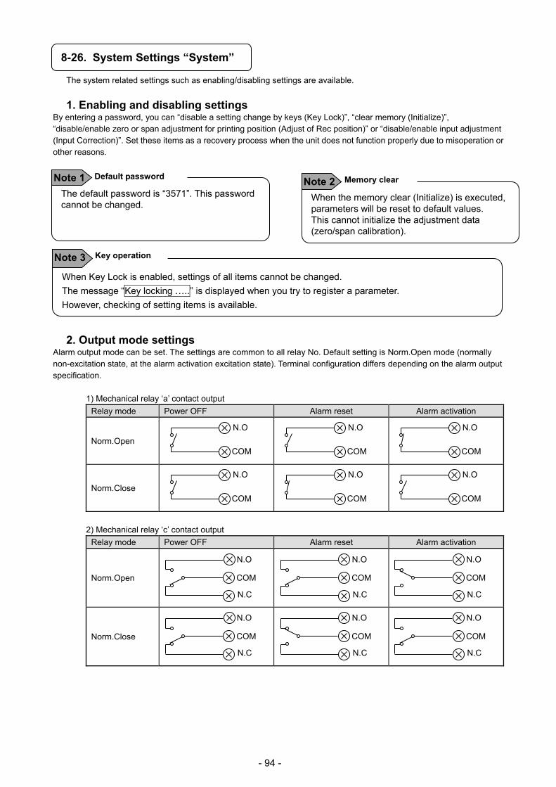
- 94 -
8-26. System Settings “System”
The system related settings such as enabling/disabling settings are available.
1. Enabling and disabling settings By entering a password, you can “disable a setting change by keys (Key Lock)”, “clear memory (Initialize)”, “disable/enable zero or span adjustment for printing position (Adjust of Rec position)” or “disable/enable input adjustment (Input Correction)”. Set these items as a recovery process when the unit does not function properly due to misoperation or other reasons.
2. Output mode settings
Alarm output mode can be set. The settings are common to all relay No. Default setting is Norm.Open mode (normally non-excitation state, at the alarm activation excitation state). Terminal configuration differs depending on the alarm output specification.
1) Mechanical relay ‘a’ contact output
Relay mode Power OFF Alarm reset Alarm activation
Norm.Open
Norm.Close
2) Mechanical relay ‘c’ contact output
Relay mode Power OFF Alarm reset Alarm activation
Norm.Open
Norm.Close
N.O
COM
N.C
N.O
COM
N.C
N.O
COM
N.C
N.O
COM
N.C
N.O
COM
N.C
N.O
COM
N.C
N.O
COM
N.O
COM
N.O
COM
N.O
COM
N.O
COM
N.O
COM
When Key Lock is enabled, settings of all items cannot be changed.
The message “Key locking …..” is displayed when you try to register a parameter.
However, checking of setting items is available.
Key operation Note 3
The default password is “3571”. This password cannot be changed.
Default password Note 1
When the memory clear (Initialize) is executed, parameters will be reset to default values. This cannot initialize the adjustment data (zero/span calibration).
Memory clear Note 2
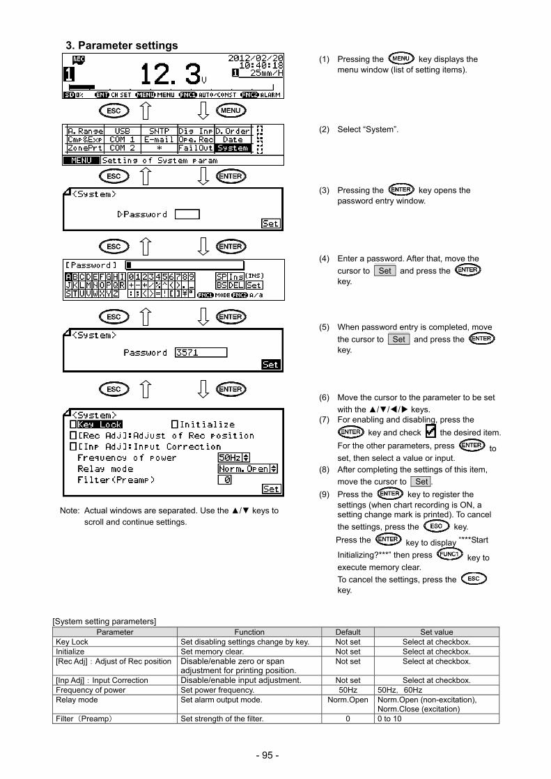
- 95 -
3. Parameter settings (1) Pressing the key displays the
menu window (list of setting items).
(2) Select “System”.
(3) Pressing the key opens the password entry window.
(4) Enter a password. After that, move the
cursor to Set and press the key.
(5) When password entry is completed, move
the cursor to Set and press the key.
(6) Move the cursor to the parameter to be set
with the // / keys. (7) For enabling and disabling, press the
key and check the desired item.
For the other parameters, press to set, then select a value or input.
(8) After completing the settings of this item,
move the cursor to Set .
(9) Press the key to register the settings (when chart recording is ON, a setting change mark is printed). To cancel
the settings, press the key.
Press the key to display “***Start
Initializing?***” then press key to execute memory clear.
To cancel the settings, press the key.
[System setting parameters] Parameter Function Default Set value
Key Lock Set disabling settings change by key. Not set Select at checkbox. Initialize Set memory clear. Not set Select at checkbox. [Rec Adj]:Adjust of Rec position Disable/enable zero or span
adjustment for printing position. Not set Select at checkbox.
[Inp Adj]:Input Correction Disable/enable input adjustment. Not set Select at checkbox. Frequency of power Set power frequency. 50Hz 50Hz,60Hz Relay mode Set alarm output mode. Norm.Open Norm.Open (non-excitation),
Norm.Close (excitation) Filter(Preamp) Set strength of the filter. 0 0 to 10
Note: Actual windows are separated. Use the / keys to scroll and continue settings.

- 96 -
8-27. System Information Display “SysInfo”
The system information display shows the model, serial number, software version of CPU used (for preamplifier, printer and other application), MAC address (Ethernet specification only) and status of system.
(1) Pressing the key displays the
menu window (list of setting items). (2) Select “SysInfo”.
(3) Pressing the key displays the system information.
Item Contents
TYPE Model code of the unit (“-” excluded)
No. Serial number of the unit
MAC Adr. MAC address of the unit using Ethernet option * This field is left blank when Ethernet option is not used.
SP Additional information (0X00000000 displayed normally)
System Value Value depends on the unit specification
P Printer software version
A, E Application software version
I Preamplifier software version
S1 to S4 Analog pen control part software version
ALM1 to ALM4 Alarm unit software version
Battery Clock backup voltage

- 97 -
9. Adjustment The unit provides four adjustment functions. Perform a suitable adjustment depending on the situation. All adjustments are processed in the software and mechanical adjustment such as trimmer adjustment is not necessary. Available adjustments are “trace printing position adjustment”, “input (measurement) adjustment”, “input (measurement) shift adjustment” and “recording position (time) adjustment”.
9-1. Trace Printing Position Adjustment “Rec Adj”
Perform zero/span adjustment for cartridge pen and plotter pen position on a chart. This adjustment does not affect the measured value. Before performing this adjustment, enable “Adjust of Rec position” according to “8-26. System Settings”. When it is enabled, “Rec Adj” is shown on the menu window (list of setting items).
(1) Pressing the key displays the
menu window (list of setting items). (2) Select “Rec Adj”.
(3) Set pen No. with the / keys. Each time
pressing the key changes Pen1 → Pen2
→ Pen3 → Pen4 → Plot. (plotter pen). The
zero and span values currently set are shown on this window. These values are
replaced by new values, when the key is pressed after completing the adjustments.
(4) Press the key to select zero, or the
key to select span.

- 98 -
[Zero adjustment]
(5) Pressing the key moves the pen to the zero side and pen recording starts while feeding the chart.
(6) Move the pen with the / keys so that pen recording is aligned to the chart 0% position.
(7) When the adjustment is completed, press the key to register the zero position.
[Span adjustment]
(5) Pressing the key moves the pen to the span side and pen recording starts while feeding the chart.
(6) Move the pen with the / keys so that pen recording is aligned to the chart 100% position.
(7) When the adjustment is completed, press the key to register the span position.
(8) While the adjustment window is displayed, you can perform adjustment by pressing the key or
key as many times as you need. When the adjustment is completed, press the key to exit the trace printing position adjustment.
Zero and span can be adjusted separately. To adjust the 0% position only, press the key when the adjustment is completed.
Zero/span individual adjustment Note 2 Unless the / key is pressed, dotting at 0% or 100% position is performed using the currently set adjustment data. When adjustment is not necessary, just press the key.
Dotting at zero/span side Note 1
Pens stand by near the center.
Pens other than set pen No.Reference
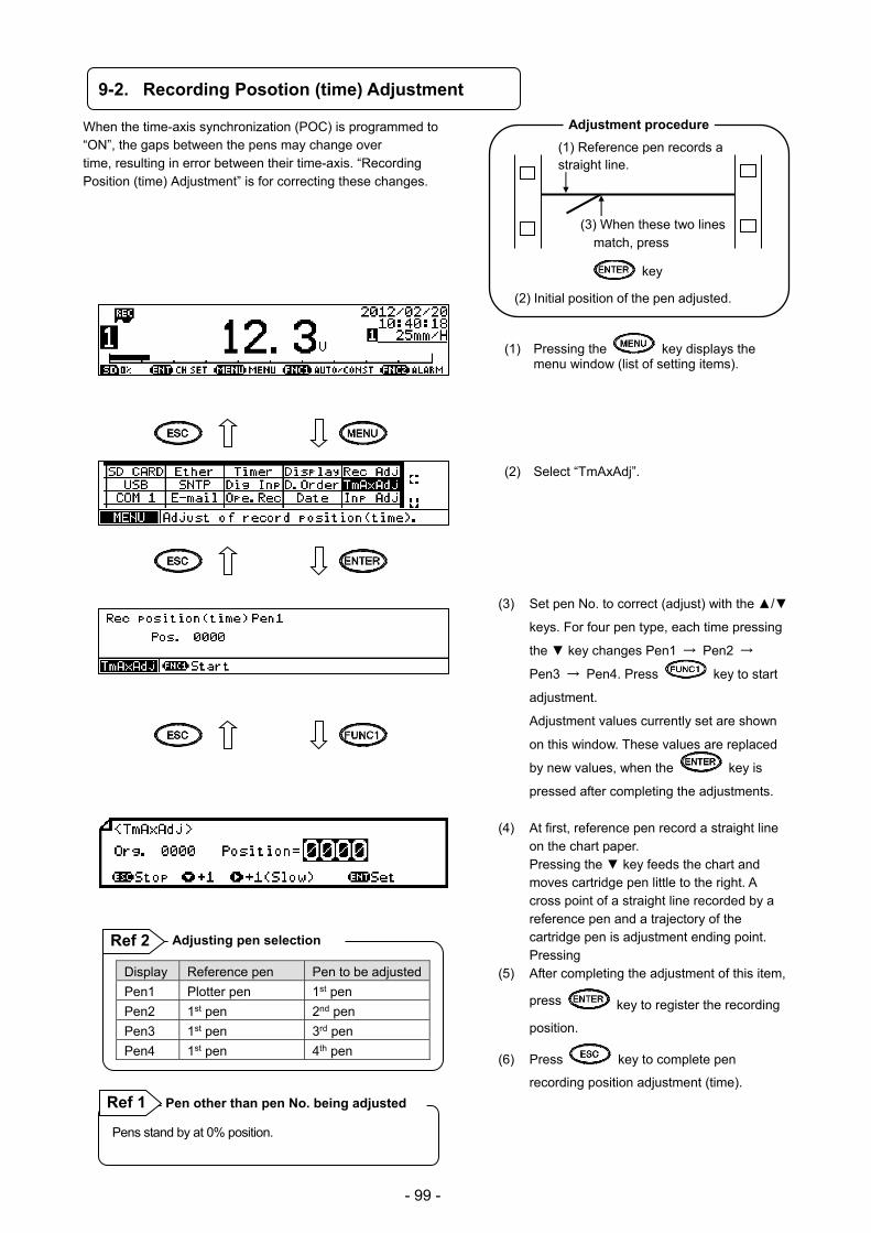
- 99 -
9-2. Recording Posotion (time) Adjustment
When the time-axis synchronization (POC) is programmed to “ON”, the gaps between the pens may change over time, resulting in error between their time-axis. “Recording Position (time) Adjustment” is for correcting these changes.
(1) Pressing the key displays the menu window (list of setting items).
(2) Select “TmAxAdj”.
(3) Set pen No. to correct (adjust) with the /
keys. For four pen type, each time pressing
the key changes Pen1 → Pen2 →
Pen3 → Pen4. Press key to start
adjustment.
Adjustment values currently set are shown
on this window. These values are replaced
by new values, when the key is
pressed after completing the adjustments.
(4) At first, reference pen record a straight line
on the chart paper. Pressing the key feeds the chart and
moves cartridge pen little to the right. A cross point of a straight line recorded by a reference pen and a trajectory of the cartridge pen is adjustment ending point.
Pressing (5) After completing the adjustment of this item,
press key to register the recording
position.
(6) Press key to complete pen
recording position adjustment (time).
Display Reference pen Pen to be adjusted
Pen1 Plotter pen 1st pen
Pen2 1st pen 2nd pen
Pen3 1st pen 3rd pen
Pen4 1st pen 4th pen
Adjusting pen selection Ref 2
Pens stand by at 0% position.
Pen other than pen No. being adjusted Ref 1
Adjustment procedure
(1) Reference pen records a straight line.
(3) When these two lines match, press
key
(2) Initial position of the pen adjusted.
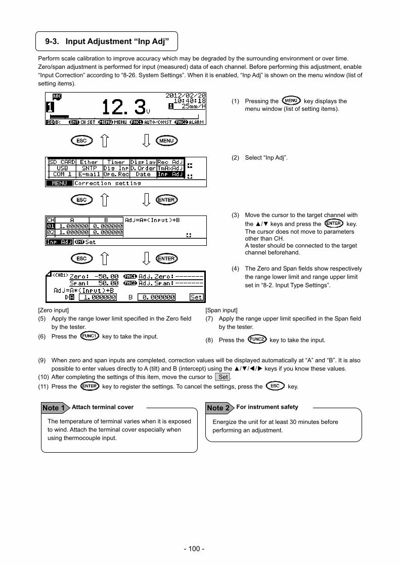
- 100 -
9-3. Input Adjustment “Inp Adj”
Perform scale calibration to improve accuracy which may be degraded by the surrounding environment or over time. Zero/span adjustment is performed for input (measured) data of each channel. Before performing this adjustment, enable “Input Correction” according to “8-26. System Settings”. When it is enabled, “Inp Adj” is shown on the menu window (list of setting items).
(1) Pressing the key displays the
menu window (list of setting items). (2) Select “Inp Adj”. (3) Move the cursor to the target channel with
the / keys and press the key. The cursor does not move to parameters other than CH. A tester should be connected to the target channel beforehand.
(4) The Zero and Span fields show respectively
the range lower limit and range upper limit set in “8-2. Input Type Settings”.
[Zero input] (5) Apply the range lower limit specified in the Zero field
by the tester.
(6) Press the key to take the input.
[Span input] (7) Apply the range upper limit specified in the Span field
by the tester.
(8) Press the key to take the input.
(9) When zero and span inputs are completed, correction values will be displayed automatically at “A” and “B”. It is also possible to enter values directly to A (tilt) and B (intercept) using the /// keys if you know these values.
(10) After completing the settings of this item, move the cursor to Set .
(11) Press the key to register the settings. To cancel the settings, press the key.
Energize the unit for at least 30 minutes before performing an adjustment.
For instrument safety Note 2 The temperature of terminal varies when it is exposed to wind. Attach the terminal cover especially when using thermocouple input.
Attach terminal cover Note 1
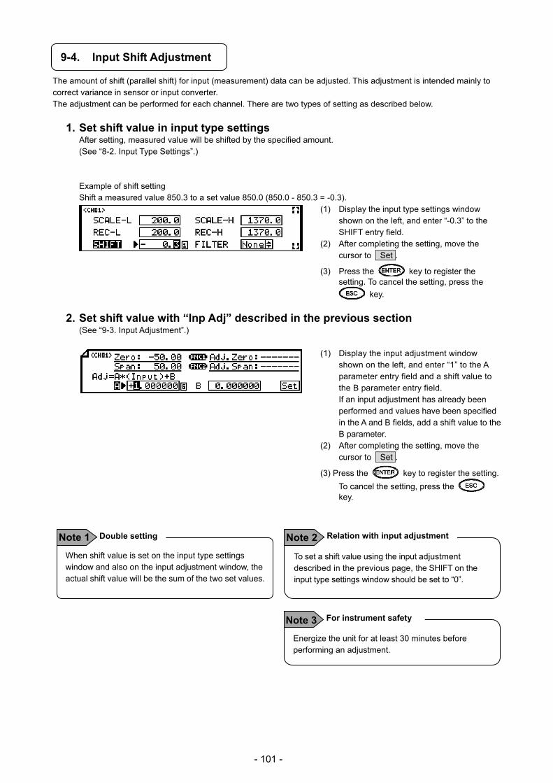
- 101 -
9-4. Input Shift Adjustment
The amount of shift (parallel shift) for input (measurement) data can be adjusted. This adjustment is intended mainly to correct variance in sensor or input converter. The adjustment can be performed for each channel. There are two types of setting as described below.
1. Set shift value in input type settings After setting, measured value will be shifted by the specified amount. (See “8-2. Input Type Settings”.)
Example of shift setting Shift a measured value 850.3 to a set value 850.0 (850.0 - 850.3 = -0.3).
(1) Display the input type settings window shown on the left, and enter “-0.3” to the SHIFT entry field.
(2) After completing the setting, move the cursor to Set .
(3) Press the key to register the setting. To cancel the setting, press the
key.
2. Set shift value with “Inp Adj” described in the previous section (See “9-3. Input Adjustment”.)
(1) Display the input adjustment window shown on the left, and enter “1” to the A parameter entry field and a shift value to the B parameter entry field.
If an input adjustment has already been performed and values have been specified in the A and B fields, add a shift value to the B parameter.
(2) After completing the setting, move the cursor to Set .
(3) Press the key to register the setting.
To cancel the setting, press the key.
When shift value is set on the input type settings window and also on the input adjustment window, the actual shift value will be the sum of the two set values.
Double setting Note 1 To set a shift value using the input adjustment described in the previous page, the SHIFT on the input type settings window should be set to “0”.
Relation with input adjustment Note 2
Energize the unit for at least 30 minutes before performing an adjustment.
For instrument safety Note 3
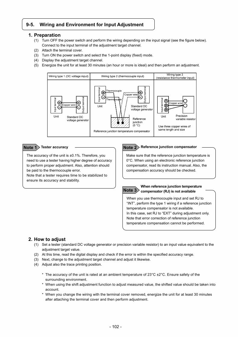
- 102 -
9-5. Wiring and Environment for Input Adjustment
1. Preparation (1) Turn OFF the power switch and perform the wiring depending on the input signal (see the figure below).
Connect to the input terminal of the adjustment target channel. (2) Attach the terminal cover. (3) Turn ON the power switch and select the 1-point display (fixed) mode. (4) Display the adjustment target channel. (5) Energize the unit for at least 30 minutes (an hour or more is ideal) and then perform an adjustment.
2. How to adjust (1) Set a tester (standard DC voltage generator or precision variable resistor) to an input value equivalent to the
adjustment target value. (2) At this time, read the digital display and check if the error is within the specified accuracy range. (3) Next, change to the adjustment target channel and adjust it likewise. (4) Adjust also the trace printing position.
* The accuracy of the unit is rated at an ambient temperature of 23°C ±2°C. Ensure safety of the surrounding environment.
* When using the shift adjustment function to adjust measured value, the shifted value should be taken into account.
* When you change the wiring with the terminal cover removed, energize the unit for at least 30 minutes after attaching the terminal cover and then perform adjustment.
The accuracy of the unit is ±0.1%. Therefore, you need to use a tester having higher degree of accuracy to perform proper adjustment. Also, attention should be paid to the thermocouple error. Note that a tester requires time to be stabilized to ensure its accuracy and stability.
Tester accuracy Note 1 Make sure that the reference junction temperature is 0°C. When using an electronic reference junction compensator, read its instruction manual. Also, the compensation accuracy should be checked.
Reference junction compensator Note 2
When you use thermocouple input and set RJ to “INT”, perform the type 1 wiring if a reference junction temperature compensator is not available. In this case, set RJ to “EXT” during adjustment only. Note that error correction of reference junction temperature compensation cannot be performed.
When reference junction temperature compensator (RJ) is not available Note 3

- 103 -
10. Engineering Port (mini-USB Terminal)
An engineering port is provided in the front section of the unit to allow connection to a personal computer. This port is provided to all models as a standard feature. Use a mini-USB cable to connect to a personal computer.
Note that this engineering port is designed for temporary communication connection and not intended for always-on connection. To obtain always-on connection for communication, you need to request the model with communication interface at the time of purchase, and use the terminal located at the rear side of the unit for permanent connection.
Make sure to attach or remove an engineering cable to/from the engineering port while the unit is turned on.
Engineering port (mini-USB)
! Caution

- 104 -
11. Troubleshooting
11-1. Problems and Remedies
The following table lists problems that may occur on the unit (operations and functions) with description of the symptoms, their possible causes and remedies.
Never replace parts to repair or modify the unit. Not only does it fail to repair or modify, but it also may cause electric shock or damage to the unit.
Symptom Cause/Remedy
(1) Unit does not function even the power switch is turned ON
(1) Check the wiring to the power terminal. (See “4-3.3. Power/protective conductor terminals wiring”.)
(2) Make sure that the power voltage is AC100 to 240V.
(2) Noise produced as printer moves
(1) Check if the cartridge pen is attached properly. (See “6-1.2. How to set plotter pen and cartridge pen”.)
(2) Open the unit door and check the printer moving area for foreign matter. Remove it if exists.
(3) Data displayed but not recorded
(1) Make sure that the recording is ON (“REC” status LED lights up).(See “6-2.3. Chart recording operation”.)
(2) Check if the ribbon cassette is attached properly. (See “6-1.2. How to set plotter pen and cartridge pen”.)
(3) Check if the chart is attached properly or if it has run out (“REC” status LED flashes). (See “6-1.1. How to set chart paper”.)
(4) Chart does not move as printer moves
(1) Feed the chart paper manually and make sure that the chart can be fed smoothly.
(2) Make sure that the chart can be fed smoothly with the key. (See “6-2.3. Chart recording operation”.)
(5) , , keys not accepted
Check the system settings. (See “8-26. System Settings”.)
While Key Lock is active, is shown on the display.
(6) Range setting done, but data display or trace/digital printing not performed on a certain channel
(1) Check the setting (ON/OFF) of each operation in input type settings. (See “8-2. Input Type Settings”.)
(7) Parameters set correctly, but not reflected on the window when checked
When a setting is changed while the chart recording is ON, a setting change mark is printed on a chart. Check the chart to see if it is printed. If not, the following situation is a possible cause. You have not pressed the key after moving the cursor to Set , or there was an error in the set contents.
(8) Parameters set correctly, but normal display does not return
(9) Periodic data printing set, but not executed
(1) The start time set for periodic data printing has not come yet. (2) Parameters are not set correctly.
(See “8-10 and 8-11. Periodic Data Printing Settings”.) * When you specify a start time which is earlier than the time of
setting, periodic data printing will be executed from the next day at the specified time.
(10) Malfunction occurred unpredictably without warning
Initialize setting parameters. (See “8-26. System Settings”.) When the unit is recovered, set parameters again and see how it works.
! Warning
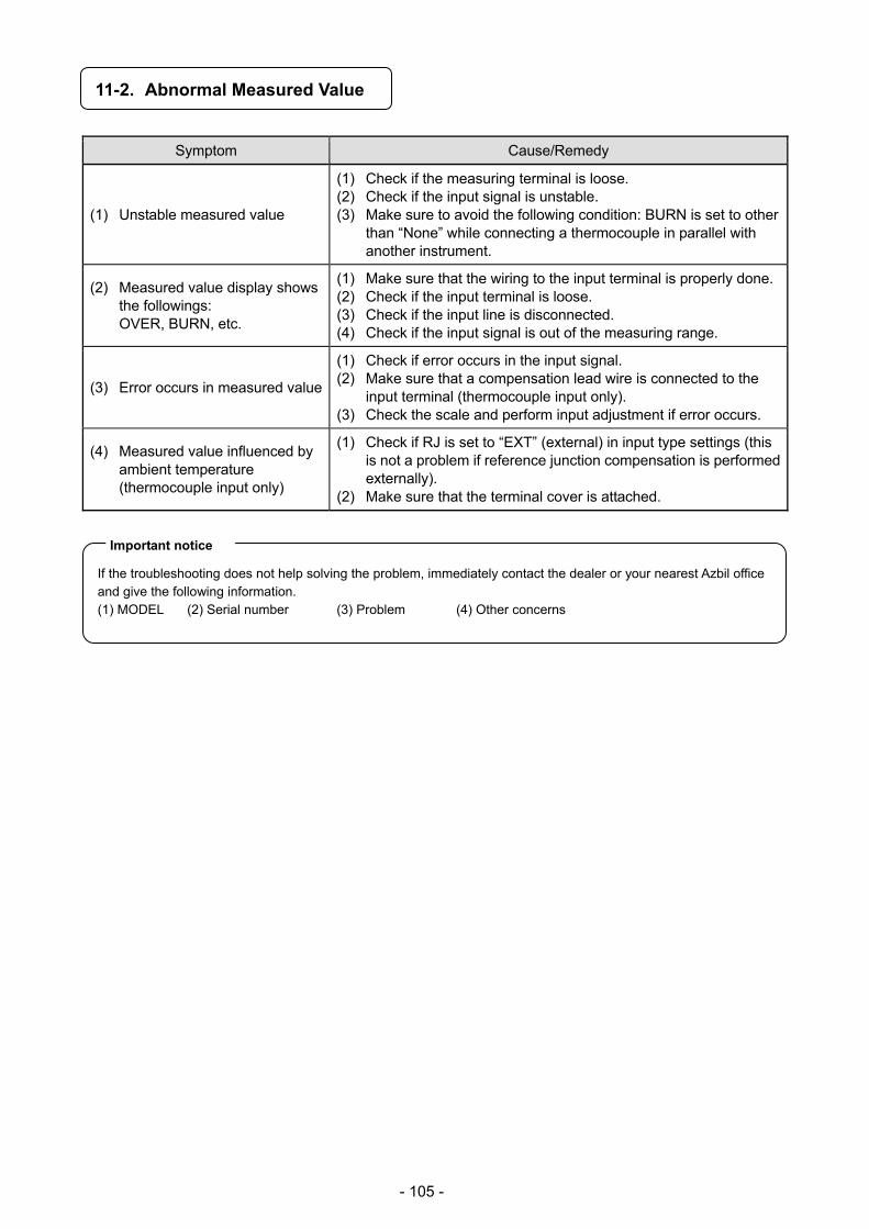
- 105 -
11-2. Abnormal Measured Value
Symptom Cause/Remedy
(1) Unstable measured value
(1) Check if the measuring terminal is loose. (2) Check if the input signal is unstable. (3) Make sure to avoid the following condition: BURN is set to other
than “None” while connecting a thermocouple in parallel with another instrument.
(2) Measured value display shows the followings: OVER, BURN, etc.
(1) Make sure that the wiring to the input terminal is properly done. (2) Check if the input terminal is loose. (3) Check if the input line is disconnected. (4) Check if the input signal is out of the measuring range.
(3) Error occurs in measured value
(1) Check if error occurs in the input signal. (2) Make sure that a compensation lead wire is connected to the
input terminal (thermocouple input only). (3) Check the scale and perform input adjustment if error occurs.
(4) Measured value influenced by ambient temperature (thermocouple input only)
(1) Check if RJ is set to “EXT” (external) in input type settings (this is not a problem if reference junction compensation is performed externally).
(2) Make sure that the terminal cover is attached.
If the troubleshooting does not help solving the problem, immediately contact the dealer or your nearest Azbil office and give the following information. (1) MODEL (2) Serial number (3) Problem (4) Other concerns
Important notice

- 106 -
12. Inspection and Maintenance
12-1. Routine Inspection
Check the remaining amount of chart and recording condition on a daily basis to keep the unit in good condition. When any abnormality is found, take an appropriate action according to the “11. Troubleshooting”.
Maintenance/inspection item Operation
Plotter pen and cartridge pen replacement
When the trace printing (trend line) fade away or becomes less visible, replace the cartridge pen with new one. When the letters of digital printing fade away or become less visible, replace the plotter pen with new one. (See “6-1.2. How to set plotter pen and cartridge pen”.)
Chart replacement
A chart paper can last about 20 days when fed at a speed of 20mm/H continuously. When the end of chart nears, an end mark (red line on the right edge of chart) appears. In this case, replace the chart with new one. (See “6-1.1. How to set chart paper”.)
Cleaning Wipe away dirt on the unit with a soft, dry cloth or a cloth dampened with warm water or neutral detergent.
Do not use chemical solvents including thinner and benzine to prevent the unit surface from melting. The chart guide is made of acrylic. It may produce a crack when a chemical solvent is used.
12-2. Consumable Parts and Replacement Guideline
The unit includes some consumable parts. To use the unit for a long time in good condition, we recommend that these parts be replaced regularly.
Do not replace parts other than chart and pens by yourself. Not only does it fail to replace properly, but it also may pose dangerous situation. Make sure to contact Azbil’s sales agent for replacement of consumable parts.
1. Consumable parts and recommended replacement cycle
(Usage under the condition of temperature: 20 to 25°C, humidity: 20 to 80%RH, operation time: 8hours/ a day) Consumable part Replacement cycle Other operating condition
Mechanical
parts
Pen servo (for cartridge pen) 4 to 6 years Use under the normal condition as below: No corrosive gas Dust free, oil smoke free, dry place Free from vibration and impact No other factors affecting operation
Pen servo (for plotter pen) 4 to 6 years
Belt 4 to 6 years
Chart drive mechanism 4 to 6 years
Motors 4 to 6 years
Electronic parts
Power supply 5 years At an ambient temperature of 25°C
Relay (for alarm) 100,000 times Resistive load 30,000 times Inductive load
Lithium battery 10 years 8-hour operation per day (at an ambient temperature of 40°C or lower)
Keys 500,000 times Depends highly on the use and surrounding conditions.
Display (LCD) 4 to 6 years At an ambient temperature of 25°C
! Caution
! Warning

- 107 -
12-3. Battery removal method for the purpose of disposa
Do not replace the battery. Doing so might cause damage or malfunction. Do not remove the battery except when disposing the recorder.
1. Removing the battery
1) Removing the internal chassis (1) Open the unit door and then open the display board in the same direction. (2) Turn OFF the power switch. (3) Remove three screws fixing the internal chassis and pull out the internal chassis.
Internal Chassis Fixing Screws
Internal Chassis Fixing Screw
2) Removing the battery
(1) Pull the printed board backward. (2) Battery is located at the back of the internal chassis.
Printed board
Battery
! Caution

- 108 -
(3) Using a tapered, insulated tool, remove the battery from the battery holder.
(1) The unit components include a small amount of harmful chemical substance no more than the defined amount by RoHS.
(2) The unit must be disposed of by a waste disposal company or in accordance with the local regulations.
(3) The unit uses a lithium battery and the battery must be disposed of by a waste disposal company.
(4) The packing materials used for the unit, such as box, plastic bag, cushion and sticker, should be sorted for recycling in accordance with local regulations.
! Caution
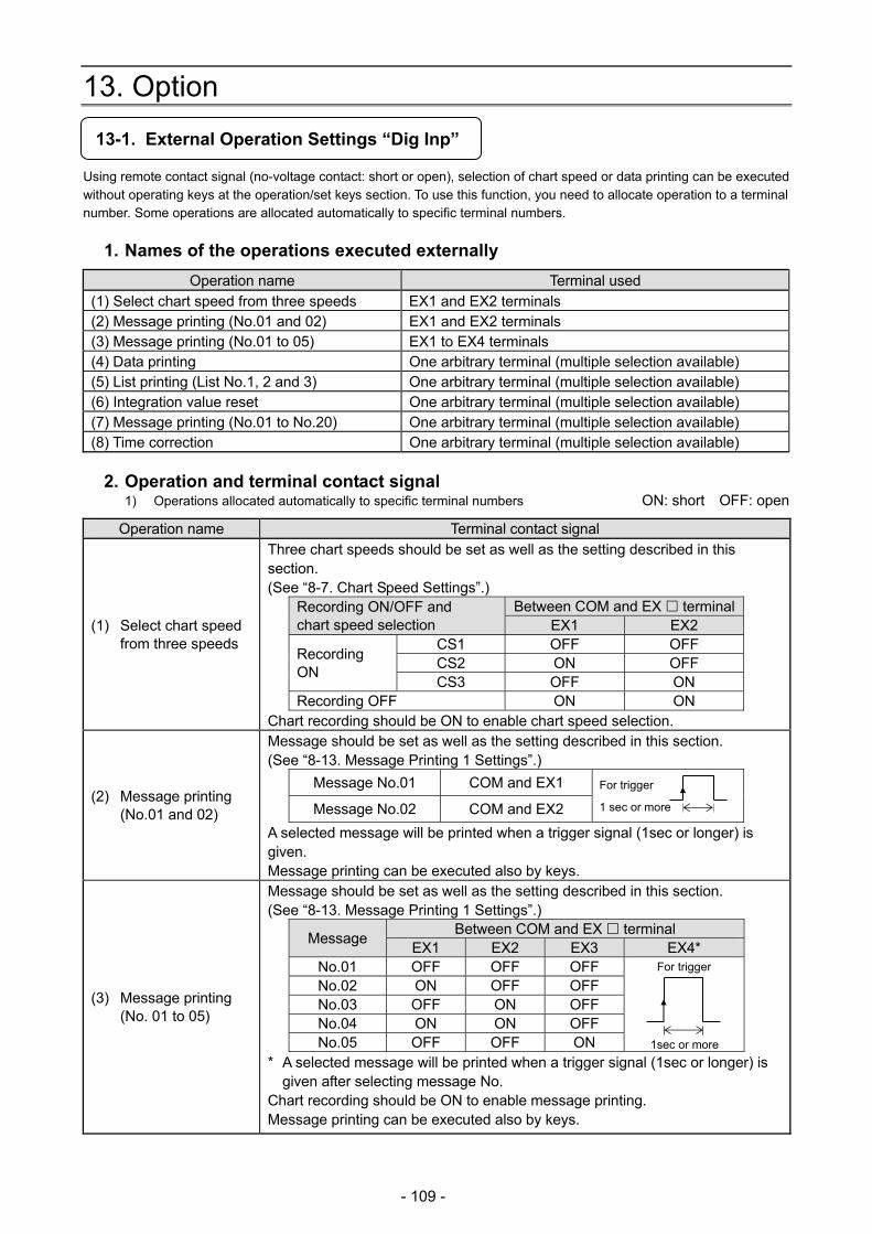
- 109 -
13. Option
13-1. External Operation Settings “Dig Inp”
Using remote contact signal (no-voltage contact: short or open), selection of chart speed or data printing can be executed without operating keys at the operation/set keys section. To use this function, you need to allocate operation to a terminal number. Some operations are allocated automatically to specific terminal numbers.
1. Names of the operations executed externally
Operation name Terminal used (1) Select chart speed from three speeds EX1 and EX2 terminals (2) Message printing (No.01 and 02) EX1 and EX2 terminals (3) Message printing (No.01 to 05) EX1 to EX4 terminals (4) Data printing One arbitrary terminal (multiple selection available) (5) List printing (List No.1, 2 and 3) One arbitrary terminal (multiple selection available) (6) Integration value reset One arbitrary terminal (multiple selection available) (7) Message printing (No.01 to No.20) One arbitrary terminal (multiple selection available) (8) Time correction One arbitrary terminal (multiple selection available)
2. Operation and terminal contact signal 1) Operations allocated automatically to specific terminal numbers ON: short OFF: open
Operation name Terminal contact signal
(1) Select chart speed from three speeds
Three chart speeds should be set as well as the setting described in this section. (See “8-7. Chart Speed Settings”.)
Recording ON/OFF and chart speed selection
Between COM and EX terminalEX1 EX2
Recording ON
CS1 OFF OFF CS2 ON OFF CS3 OFF ON
Recording OFF ON ON Chart recording should be ON to enable chart speed selection.
(2) Message printing (No.01 and 02)
Message should be set as well as the setting described in this section. (See “8-13. Message Printing 1 Settings”.)
Message No.01 COM and EX1
Message No.02 COM and EX2
A selected message will be printed when a trigger signal (1sec or longer) is given. Message printing can be executed also by keys.
(3) Message printing (No. 01 to 05)
Message should be set as well as the setting described in this section. (See “8-13. Message Printing 1 Settings”.)
Message Between COM and EX terminal
EX1 EX2 EX3 EX4* No.01 OFF OFF OFF For trigger
No.02 ON OFF OFF No.03 OFF ON OFF No.04 ON ON OFF No.05 OFF OFF ON
* A selected message will be printed when a trigger signal (1sec or longer) is given after selecting message No.
Chart recording should be ON to enable message printing. Message printing can be executed also by keys.
1 sec or more
For trigger
1sec or more

- 110 -
2) Operations allocated to arbitrary terminal numbers ON: short OFF: open
Operation name Terminal contact signal
(4) Data printing
Turn ON the terminal No. specified for data printing. Chart recording should be ON. Data printing can be executed also by keys. While executing data printing, another execution request can be accepted.
(5) List printing (List No.1, 2 and 3)
Turn ON the terminal No. specified for list 1, 2 and 3 printing. Chart recording should be ON. List printing can be executed also by keys. (See “8-12. List Printing Settings”.)
(6) Integration value reset
When “EX (All)” is selected for INT-Reset in calculation settings, integration value can be reset by turning ON the terminal No. specified for integration reset.(See “8-4. Calculation Settings”.)
(7) Message printing (No.01 to No.20)
Message should be set as well as the setting described in this section. (See “8-13. Message Printing 1 Settings”.) Turn ON the terminal No. specified for message printing (No.01 to 20). Chart recording should be ON. Message printing can be executed also by keys.
(8) Time correction
When the current time (second) is 0 to 30, the second value will be set to 0. When it is 31 to 59, the minute value will be increased by 1min and the second value will be set to 0. Example: Turn On the specified terminal No. at 10:10 and 30 seconds. The time will be set to 10:10:00. It will be 10:11:00 when the terminal is turned ON at 10:10 and 31 seconds.
For contact signal which is given to remote contact terminal, use a switch or relay operated at 30V AC, 60V DC or lower voltage level, or manually operated contact which can handle minute load.
1sec or more
! Warning
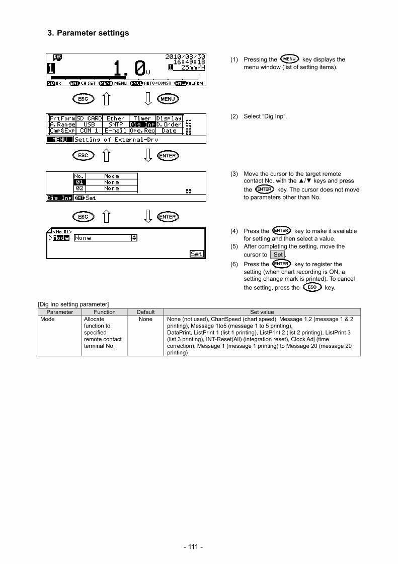
- 111 -
3. Parameter settings
(1) Pressing the key displays the menu window (list of setting items).
(2) Select “Dig Inp”. (3) Move the cursor to the target remote
contact No. with the / keys and press
the key. The cursor does not move to parameters other than No.
(4) Press the key to make it available for setting and then select a value.
(5) After completing the setting, move the cursor to Set .
(6) Press the key to register the setting (when chart recording is ON, a setting change mark is printed). To cancel
the setting, press the key.
[Dig Inp setting parameter] Parameter Function Default Set value
Mode Allocate function to specified remote contact terminal No.
None None (not used), ChartSpeed (chart speed), Message 1,2 (message 1 & 2 printing), Message 1to5 (message 1 to 5 printing), DataPrint, ListPrint 1 (list 1 printing), ListPrint 2 (list 2 printing), ListPrint 3 (list 3 printing), INT-Reset(All) (integration reset), Clock Adj (time correction), Message 1 (message 1 printing) to Message 20 (message 20 printing)

- 112 -
13-2. Operation Recording Settings “Ope.Rec”
The ON/OFF status of the remote contact input (No. 1 to 5: depending on the specification) can be recorded to chart. For a target remote contact No., specify the recording position for input OFF status (percentage value of chart span) and the recording position for input ON status by an offset (1 to 10mm) from the OFF position. When the input is ON, recording is made on the right side of the input OFF recording position, at the position specified by an arbitrary offset width. At this time, a straight line connects between ON and OFF.
(1) Pressing the key displays the menu window (list of setting items).
(2) Select “Ope.Rec”. (3) Move the cursor to the target remote
contact No. with the / keys and press
the key. The cursor does not move to parameters other than EX.
Also, pressing the key on this window displays the copy window for operation recording settings.
(4) Move the cursor to the parameter to be set
with the /// keys.
(5) Press the key to make it available for setting and then select or enter a value.
(6) After completing the settings of this item, move the cursor to Set .
(7) Press the key to register the settings (when chart recording is ON, a setting change mark is printed). To cancel
the settings, press the key.
[List of Ope.Rec setting parameters] Parameter Function Default Set value
ON/OFF Select ON or OFF for operation recording OFF ON (enabled), OFF (disabled) Position Set recording position for input OFF status to
percentage of chart zero span * 0 to 90 (%)
Width Set recording position for input ON status to millimeters of chart zero span based on the input OFF recording position.
* 1 to10 [mm]
Operation recording line and remote contact No.
Setting range
#1
#2 Remote contact No.
Lines recorded when open
Lines recorded when short
Specify width
0 90(%)
Specify width

- 113 -
13-3. COM Port Settings “COM1” and “COM2”
COM port 1 and COM port 2 can be set separately to use them simultaneously. These ports are mainly used to set the unit using PLC or PC, and load measured data. This section describes the things related to settings only. For general handling information, refer to the instruction manual for “Communication Interface” provided separately.
(1) Pressing the key displays the menu window (list of setting items).
(2) Select “COM1” or “COM2”. (3) Move the cursor to the parameter to be set
with the /// keys.
(4) Press the key to make it available for setting and then select or enter a value.
(5) After completing the settings of this item, move the cursor to Set .
(6) Press the key to register the settings (when chart recording is ON, a setting change mark is printed). To cancel
the settings, press the key.
[List of COM1 and COM2 setting parameters] Parameter Function Default Set value
Mode Communication mode Low (To PC etc…) Fixed to Low (To PC etc…) Protocol Select communication
protocol MODBUS RTU MODBUS RTU, MODBUS ASCII, PRIVATE1 (without
connection sequence), PRIVATE2 (with connection sequence)
Address Set communication address of the unit
01 01 to 99
Baud rate Set communication speed 9600 PRIVATE: 1200, 2400, 4800, 9600bps MODBUS: 9600, 19200, 38400bps Changes to “9600” when changing from PRIVATE to MODBUS or vice versa.
Character Set transmission character 8N1 7E1, 7E2, 7O1, 7O2, 8N1, 8N2, 8E1, 8E2, 8O1, 8O2 Check SUM Select whether to add
checksum code * OFF, ON
Settable only when Protocol is set to “PRIVATE”.
Note: Actual windows are separated. Use the / keys to scroll and continue settings.
Codes are used to represent character type.
Code Character length Parity Stop bit Code Character length Parity Stop bit 7E1 7-bit Even 1 8N2 8-bit Non 2 7E2 7-bit Even 2 8E1 8-bit Even 1 7O1 7-bit Odd 1 8E2 8-bit Even 2 7O2 7-bit Odd 2 8O1 8-bit Odd 1 8N1 8-bit Non 1 8O2 8-bit Odd 2
Character selection Reference
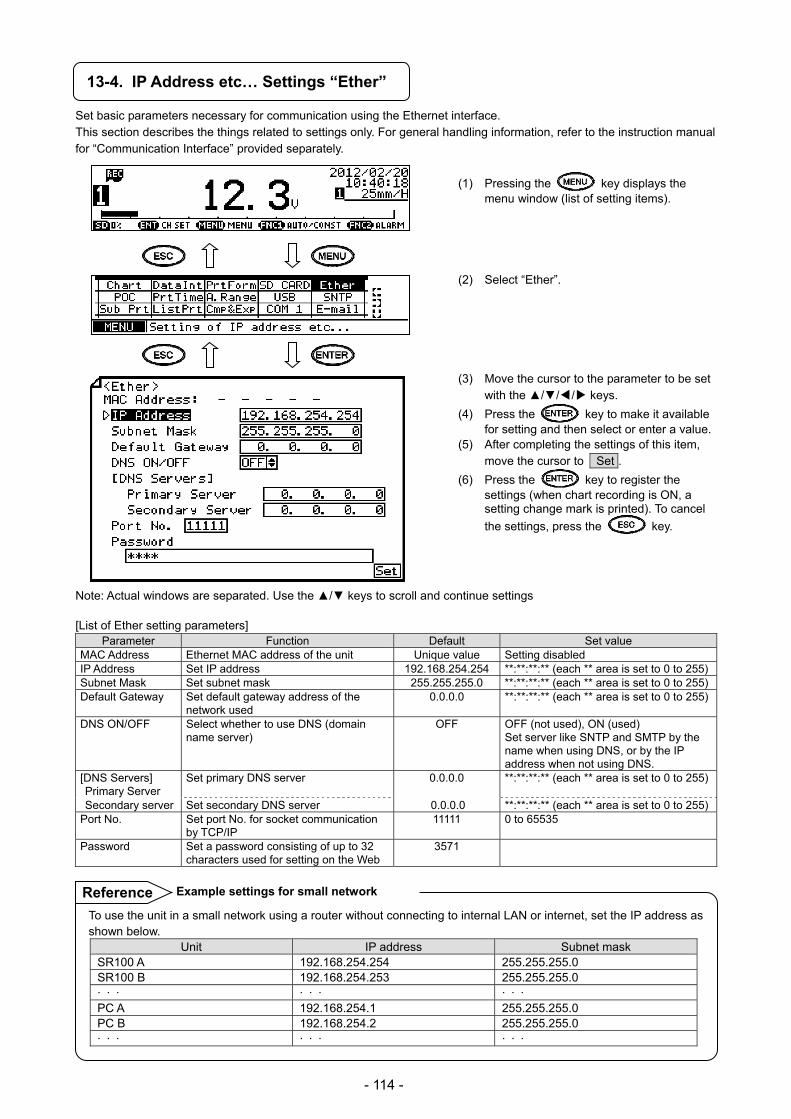
- 114 -
13-4. IP Address etc… Settings “Ether”
Set basic parameters necessary for communication using the Ethernet interface. This section describes the things related to settings only. For general handling information, refer to the instruction manual for “Communication Interface” provided separately.
(1) Pressing the key displays the menu window (list of setting items).
(2) Select “Ether”. (3) Move the cursor to the parameter to be set
with the /// keys.
(4) Press the key to make it available for setting and then select or enter a value.
(5) After completing the settings of this item, move the cursor to Set .
(6) Press the key to register the settings (when chart recording is ON, a setting change mark is printed). To cancel
the settings, press the key.
Note: Actual windows are separated. Use the / keys to scroll and continue settings
[List of Ether setting parameters] Parameter Function Default Set value
MAC Address Ethernet MAC address of the unit Unique value Setting disabled IP Address Set IP address 192.168.254.254 **:**:**:** (each ** area is set to 0 to 255)Subnet Mask Set subnet mask 255.255.255.0 **:**:**:** (each ** area is set to 0 to 255)Default Gateway Set default gateway address of the
network used 0.0.0.0 **:**:**:** (each ** area is set to 0 to 255)
DNS ON/OFF Select whether to use DNS (domain name server)
OFF OFF (not used), ON (used) Set server like SNTP and SMTP by the name when using DNS, or by the IP address when not using DNS.
[DNS Servers] Primary Server
Set primary DNS server 0.0.0.0 **:**:**:** (each ** area is set to 0 to 255)
Secondary server Set secondary DNS server 0.0.0.0 **:**:**:** (each ** area is set to 0 to 255)Port No. Set port No. for socket communication
by TCP/IP 11111 0 to 65535
Password Set a password consisting of up to 32 characters used for setting on the Web
3571
To use the unit in a small network using a router without connecting to internal LAN or internet, set the IP address as shown below.
Unit IP address Subnet mask SR100 A 192.168.254.254 255.255.255.0 SR100 B 192.168.254.253 255.255.255.0 · · · · · · · · · PC A 192.168.254.1 255.255.255.0 PC B 192.168.254.2 255.255.255.0 · · · · · · · · ·
Example settings for small network Reference
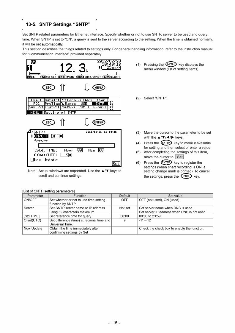
- 115 -
13-5. SNTP Settings “SNTP”
Set SNTP related parameters for Ethernet interface. Specify whether or not to use SNTP, server to be used and query time. When SNTP is set to “ON”, a query is sent to the server according to the setting. When the time is obtained normally, it will be set automatically. This section describes the things related to settings only. For general handling information, refer to the instruction manual for “Communication Interface” provided separately.
(1) Pressing the key displays the menu window (list of setting items).
(2) Select “SNTP”. (3) Move the cursor to the parameter to be set
with the /// keys.
(4) Press the key to make it available for setting and then select or enter a value.
(5) After completing the settings of this item, move the cursor to Set .
(6) Press the key to register the settings (when chart recording is ON, a setting change mark is printed). To cancel
the settings, press the key.
[List of SNTP setting parameters] Parameter Function Default Set value
ON/OFF Set whether or not to use time setting function by SNTP
OFF OFF (not used), ON (used)
Server Set SNTP server name or IP address using 32 characters maximum
Not set Set server name when DNS is used. Set server IP address when DNS is not used.
[Std.TIME] Set reference time for query 00:00 00:00 to 23:59 Ofset(UTC) Set difference (time) at regional time and
Universal Time. 9 -11-12
Now Update Obtain the time immediately after confirming settings by Set
Check the check box to enable the function.
Note: Actual windows are separated. Use the / keys to scroll and continue settings
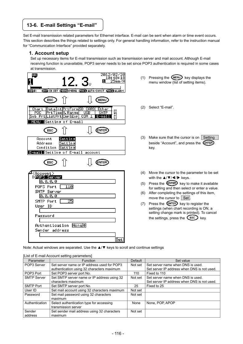
- 116 -
13-6. E-mail Settings “E-mail”
Set E-mail transmission related parameters for Ethernet interface. E-mail can be sent when alarm or time event occurs. This section describes the things related to settings only. For general handling information, refer to the instruction manual for “Communication Interface” provided separately.
1. Account setup Set up necessary items for E-mail transmission such as transmission server and mail account. Although E-mail receiving function is unavailable, POP3 server needs to be set since POP3 authentication is required in some cases at transmission.
(1) Pressing the key displays the menu window (list of setting items).
(2) Select “E-mail”. (3) Make sure that the cursor is on Setting
beside “Account”, and press the key.
(4) Move the cursor to the parameter to be set
with the /// keys.
(5) Press the key to make it available for setting and then select or enter a value.
(6) After completing the settings of this item, move the cursor to Set .
(7) Press the key to register the settings (when chart recording is ON, a setting change mark is printed). To cancel
the settings, press the key.
Note: Actual windows are separated. Use the / keys to scroll and continue settings
[List of E-mail Account setting parameters]
Parameter Function Default Set value POP3 Server Set server name or IP address used for POP3
authentication using 32 characters maximum Not set Set server name when DNS is used.
Set server IP address when DNS is not used. POP3 Port Set POP3 server port No. 110 Fixed to 110 SMTP Server Set SMTP server name or IP address using 32
characters maximum Not set Set server name when DNS is used.
Set server IP address when DNS is not used. SMTP Port Set SMTP server port No. 25 Fixed to 25 User ID Set mail account using 32 characters maximum Not set Password Set mail password using 32 characters
maximum Not set
Authentication Select authentication type for accessing transmission server
None None, POP, APOP
Sender address
Set sender mail address using 32 characters maximum
Not set
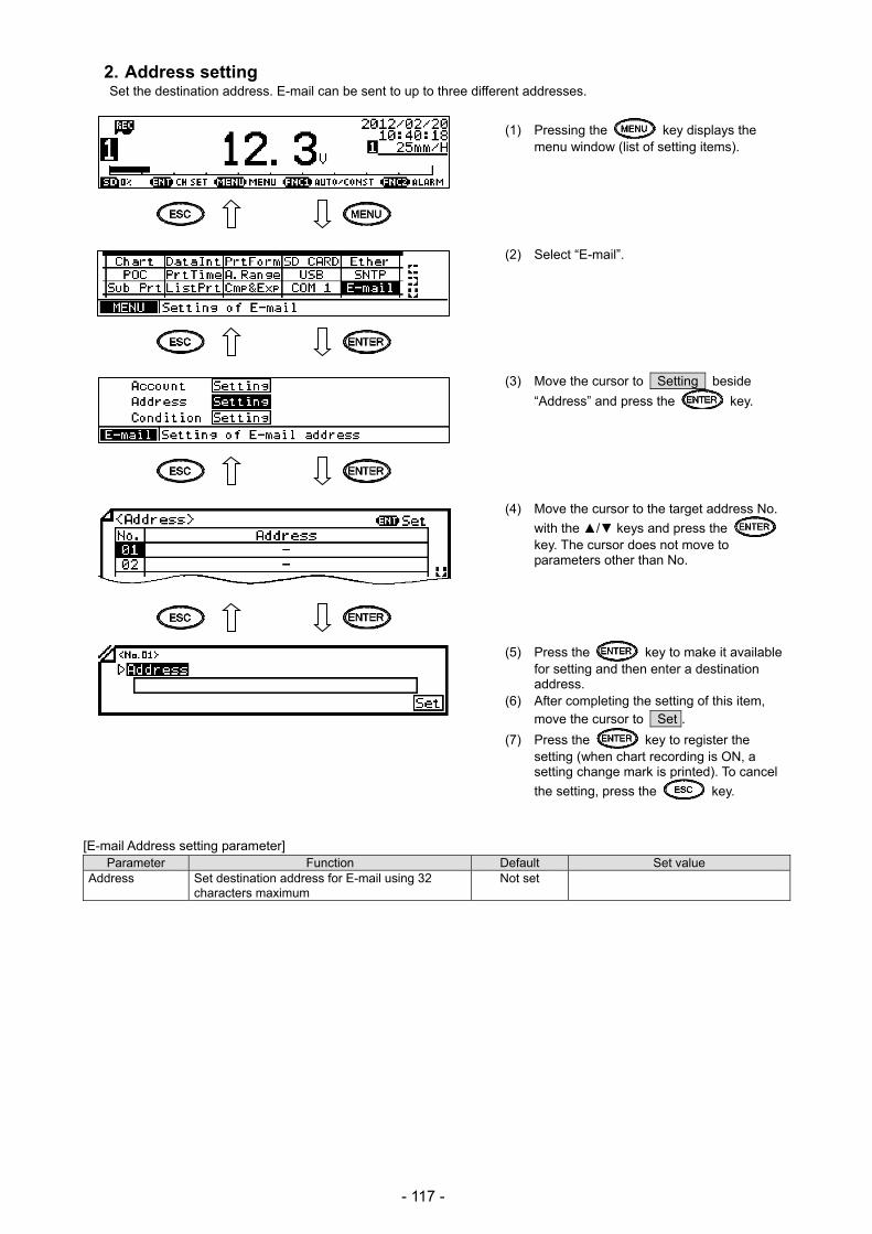
- 117 -
2. Address setting Set the destination address. E-mail can be sent to up to three different addresses.
(1) Pressing the key displays the menu window (list of setting items).
(2) Select “E-mail”. (3) Move the cursor to Setting beside
“Address” and press the key. (4) Move the cursor to the target address No.
with the / keys and press the key. The cursor does not move to parameters other than No.
(5) Press the key to make it available for setting and then enter a destination address.
(6) After completing the setting of this item, move the cursor to Set .
(7) Press the key to register the setting (when chart recording is ON, a setting change mark is printed). To cancel
the setting, press the key.
[E-mail Address setting parameter] Parameter Function Default Set value
Address Set destination address for E-mail using 32 characters maximum
Not set

- 118 -
3. Transmission condition setting Set the E-mail transmission condition. E-mail can be sent at alarm activation (when alarm is activated on the specified channel), at set time (at every interval from reference time) or at occurrence of event like chart end (see “8-23. Fail Output Settings”). Up to six conditions can be registered.
(1) Pressing the key displays the menu window (list of setting items).
(2) Select “E-mail”.
(3) Move the cursor to Setting beside
“Condition” and press the key.
(4) Move the cursor to the target condition No.
with the / keys and press the key. The cursor does not move to parameters other than No.
(5) Move the cursor to the parameter to be set
with the /// keys.
(6) Press the key to make it available
for setting and then select or enter a value.
(7) After completing the settings of this item,
move the cursor to Set .
(8) Press the key to register the
settings (when chart recording is ON, a
setting change mark is printed). To cancel
the settings, press the key. [List of E-mail Condition setting parameters]
Parameter Function Default Set value Condition Select E-mail transmission condition None None (not used), Alarm (at alarm activation),
Interval (send measured value at fixed intervals), FailOut
[Target CH] Set beginning and end of target CHs to send e-mail for alarm activation or measured value
* 1 to 4
[Std.TIME] Set reference time for sending measured data
* 00:00 to 23:59
[Interval] Set interval for sending measured data * 00:00 to 24:59 [Address No.] Select destination address for each condition Select up to three addresses from those set in the
previous section by checking desired address No.
Note: Actual windows are separated. Use the / keys to scroll and continue settings
E-mail is sent at the following time: reference time + (interval x n) n = 0, 1, 2, 3…
Example: [Std.TIME] is set to “00:00” and [Interval] is set to “04:00” E-mail will be sent at 00:00, 04:00, 08:00, 12:00, 16:00 and 20:00.
Interval setting Reference
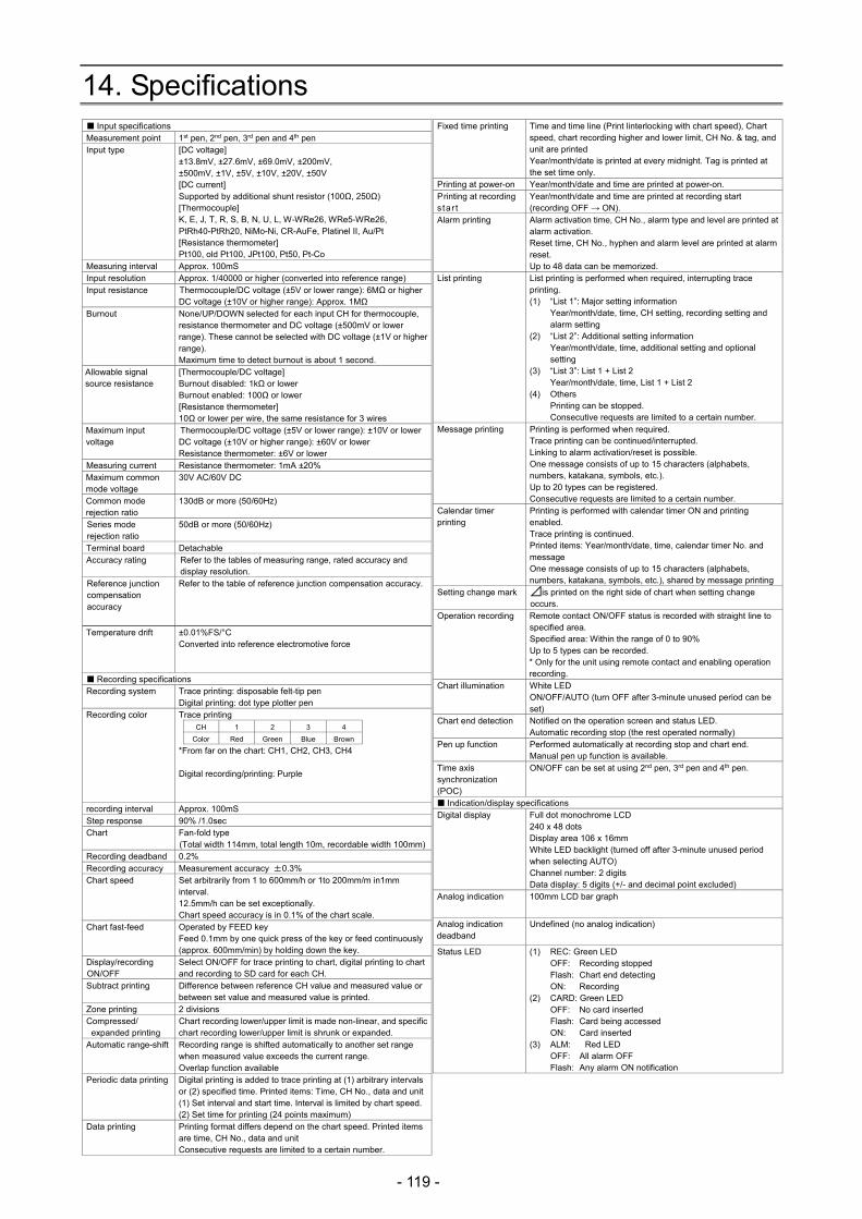
- 119 -
14. Specifications Input specifications Measurement point 1st pen, 2nd pen, 3rd pen and 4th pen Input type [DC voltage]
±13.8mV, ±27.6mV, ±69.0mV, ±200mV, ±500mV, ±1V, ±5V, ±10V, ±20V, ±50V [DC current] Supported by additional shunt resistor (100Ω, 250Ω) [Thermocouple] K, E, J, T, R, S, B, N, U, L, W-WRe26, WRe5-WRe26, PtRh40-PtRh20, NiMo-Ni, CR-AuFe, Platinel II, Au/Pt [Resistance thermometer] Pt100, old Pt100, JPt100, Pt50, Pt-Co
Measuring interval Approx. 100mS Input resolution Approx. 1/40000 or higher (converted into reference range) Input resistance Thermocouple/DC voltage (±5V or lower range): 6MΩ or higher
DC voltage (±10V or higher range): Approx. 1MΩ Burnout None/UP/DOWN selected for each input CH for thermocouple,
resistance thermometer and DC voltage (±500mV or lower range). These cannot be selected with DC voltage (±1V or higher range). Maximum time to detect burnout is about 1 second.
Allowable signal source resistance
[Thermocouple/DC voltage] Burnout disabled: 1kΩ or lower Burnout enabled: 100Ω or lower [Resistance thermometer] 10Ω or lower per wire, the same resistance for 3 wires
Maximum input voltage
Thermocouple/DC voltage (±5V or lower range): ±10V or lower DC voltage (±10V or higher range): ±60V or lower Resistance thermometer: ±6V or lower
Measuring current Resistance thermometer: 1mA ±20% Maximum common mode voltage
30V AC/60V DC
Common mode rejection ratio
130dB or more (50/60Hz)
Series mode rejection ratio
50dB or more (50/60Hz)
Terminal board Detachable Accuracy rating Refer to the tables of measuring range, rated accuracy and
display resolution. Reference junction compensation accuracy
Refer to the table of reference junction compensation accuracy.
Temperature drift
±0.01%FS/°C Converted into reference electromotive force
Recording specifications Recording system Trace printing: disposable felt-tip pen
Digital printing: dot type plotter pen Recording color Trace printing
CH 1 2 3 4
Color Red Green Blue Brown
*From far on the chart: CH1, CH2, CH3, CH4 Digital recording/printing: Purple
recording interval Approx. 100mS Step response 90% /1.0sec Chart Fan-fold type
(Total width 114mm, total length 10m, recordable width 100mm)Recording deadband 0.2% Recording accuracy Measurement accuracy ±0.3% Chart speed Set arbitrarily from 1 to 600mm/h or 1to 200mm/m in1mm
interval. 12.5mm/h can be set exceptionally. Chart speed accuracy is in 0.1% of the chart scale.
Chart fast-feed Operated by FEED key Feed 0.1mm by one quick press of the key or feed continuously (approx. 600mm/min) by holding down the key.
Display/recording ON/OFF
Select ON/OFF for trace printing to chart, digital printing to chart and recording to SD card for each CH.
Subtract printing Difference between reference CH value and measured value or between set value and measured value is printed.
Zone printing 2 divisions Compressed/
expanded printing Chart recording lower/upper limit is made non-linear, and specific chart recording lower/upper limit is shrunk or expanded.
Automatic range-shift Recording range is shifted automatically to another set range when measured value exceeds the current range. Overlap function available
Periodic data printing Digital printing is added to trace printing at (1) arbitrary intervals or (2) specified time. Printed items: Time, CH No., data and unit(1) Set interval and start time. Interval is limited by chart speed.(2) Set time for printing (24 points maximum)
Data printing Printing format differs depend on the chart speed. Printed items are time, CH No., data and unit Consecutive requests are limited to a certain number.
Fixed time printing Time and time line (Print linterlocking with chart speed), Chart speed, chart recording higher and lower limit, CH No. & tag, and unit are printed Year/month/date is printed at every midnight. Tag is printed at the set time only.
Printing at power-on Year/month/date and time are printed at power-on. Printing at recording s tar t
Year/month/date and time are printed at recording start (recording OFF → ON).
Alarm printing Alarm activation time, CH No., alarm type and level are printed at alarm activation. Reset time, CH No., hyphen and alarm level are printed at alarm reset. Up to 48 data can be memorized.
List printing List printing is performed when required, interrupting trace printing. (1) “List 1”: Major setting information
Year/month/date, time, CH setting, recording setting and alarm setting
(2) “List 2”: Additional setting information Year/month/date, time, additional setting and optional setting
(3) “List 3”: List 1 + List 2 Year/month/date, time, List 1 + List 2
(4) Others Printing can be stopped. Consecutive requests are limited to a certain number.
Message printing Printing is performed when required. Trace printing can be continued/interrupted. Linking to alarm activation/reset is possible. One message consists of up to 15 characters (alphabets, numbers, katakana, symbols, etc.). Up to 20 types can be registered. Consecutive requests are limited to a certain number.
Calendar timer printing
Printing is performed with calendar timer ON and printing enabled. Trace printing is continued. Printed items: Year/month/date, time, calendar timer No. and message One message consists of up to 15 characters (alphabets, numbers, katakana, symbols, etc.), shared by message printing
Setting change mark ⊿is printed on the right side of chart when setting change occurs.
Operation recording Remote contact ON/OFF status is recorded with straight line to specified area. Specified area: Within the range of 0 to 90% Up to 5 types can be recorded. * Only for the unit using remote contact and enabling operation recording.
Chart illumination White LED ON/OFF/AUTO (turn OFF after 3-minute unused period can be set)
Chart end detection Notified on the operation screen and status LED. Automatic recording stop (the rest operated normally)
Pen up function Performed automatically at recording stop and chart end. Manual pen up function is available.
Time axis synchronization (POC)
ON/OFF can be set at using 2nd pen, 3rd pen and 4th pen.
Indication/display specifications Digital display Full dot monochrome LCD
240 x 48 dots Display area 106 x 16mm White LED backlight (turned off after 3-minute unused period when selecting AUTO) Channel number: 2 digits Data display: 5 digits (+/- and decimal point excluded)
Analog indication 100mm LCD bar graph
Analog indication deadband
Undefined (no analog indication)
Status LED (1) REC: Green LED OFF: Recording stopped Flash: Chart end detecting ON: Recording
(2) CARD: Green LED OFF: No card inserted Flash: Card being accessed ON: Card inserted
(3) ALM: Red LED OFF: All alarm OFF Flash: Any alarm ON notification
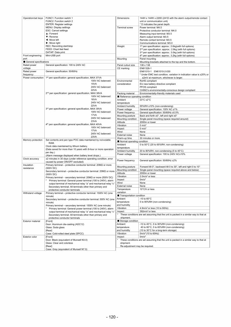
- 120 -
Operation/set keys FUNC1: Function switch 1 FUNC2: Function switch 2 ENTER: Register settings MENU: Display settings ESC: Cancel settings : Forward : Reverse : Move left : Move right REC: Recording start/stop FEED: Chart fast feed DATAP: Data print
Front engineering port
Mini-USB port
General specifications Rated power voltage
General specification: 100 to 240V AC
Rated power frequency
General specification: 50/60Hz
Power consumption 1st pen specification: general specification, MAX 37VA 100V AC balanced: 15VA 240V AC balanced: 22VA
2nd pen specification: general specification, MAX 38VA 100V AC balanced: 16VA 240V AC balanced: 22VA
3rd pen specification: general specification, MAX 39VA 100V AC balanced: 17VA 240V AC balanced: 23VA
4th pen specification: general specification, MAX 40VA 100V AC balanced: 17VA 240V AC balanced: 23VA
Memory protection Set contents and pen type POC data maintained by nonvolatile RAM.
Clock data maintained by lithium battery. (Data saved for more than 10 years with 8-hour or more operation per day.) (Alarm message displayed when battery level drops.)
Clock accuracy ±2 minutes in 30 days (under reference operating condition, error caused by power ON/OFF excluded)
Insulation resistance
Primary terminal – protective conductor terminal: 20MΩ or more (500V DC) Secondary terminal – protective conductor terminal: 20MΩ or more (500V DC) Primary terminal – secondary terminal: 20MΩ or more (500V DC) * Primary terminal: General power terminal (100 to 240V), alarm
output terminal of mechanical relay “a” and mechanical relay “c”Secondary terminal: All terminals other than primary and protective conductor terminals
Withstand voltage Primary terminal – protective conductor terminal: 1500V AC (one minute) Secondary terminal – protective conductor terminal: 500V AC (one minute) Primary terminal – secondary terminal: 1500V AC (one minute) * Primary terminal: General power terminal (100 to 240V), alarm
output terminal of mechanical relay “a” and mechanical relay “c”Secondary terminal: All terminals other than primary and protective conductor terminals
Exterior material [Front] Door: Aluminum die-casting (ADC12) Glass: Soda glass [Rear] Case: Cold-rolled steel plate (SPCC)
Exterior color [Front] Door: Black (equivalent of Munsell N3.0) Glass: Clear and colorless [Rear] Case: Gray (equivalent of Munsell N7.0)
Dimensions 144H x 144W x 220D (241D with the alarm output/remote contact unit or communication unit) * D indicates the panel depth.
Terminal screw Power terminal: M4.0 Protective conductor terminal: M4.0 Measuring input terminal: M3.5 Alarm output terminal: M3.5 Remote contact terminal: M3.5 Communications terminal: M3.0
Weight 1st pen specification: approx.: 2.6kg(with full options) 2nd pen specification: approx.: 2.8kg (with full options) 3rd pen specification: approx.: 3.0kg (with full options) 4th pen specification: approx.: 3.2kg (with full options)
Mounting Panel mounting Mounting brackets attached to the top and the bottom.
Panel cutout size 138 x 138 CE marking EN61326-1
EN61010-1 EN61010-2-030 * Under EMC test condition, variation in indication value is ±20% or
±2mV at maximum, whichever is larger. Environmental consideration
RoHS compliant EU new battery directive compliant PFOS compliant CHINO’s environmentally-conscious design compliant
Packing material Environmentally-friendly materials used Reference operating condition Ambient temperature
23°C ±2°C
Ambient humidity 55%RH ±10% (non-condensing) Power voltage General specification: 100V AC ±1% Power frequency General specification: 50/60Hz ±0.5% Mounting posture Back and forth ±0°, left and right ±0° Mounting condition Single panel mounting (space required around) Altitude 2000m or lower Vibration 0 m/s2 Impact 0 m/s2 Wind None External noise None Warm-up time 30 minutes or more
Normal operating condition Ambient temperature
0 to 50°C (20 to 65%RH, non-condensing)
Ambient humidity 20 to 80%RH, non-condensing (5 to 45°C) Power voltage General specification: 100 to 240V AC±10%
Power frequency General specification: 50/60Hz ±2%
Mounting posture Forward tilt 0°, backward tilt 0 to 30°, left and right 0 to 10° Mounting condition Single panel mounting (space required above and below) Altitude 2000m or lower Vibration 2.0m/s2 or less Impact 0m/s2 Wind None External noise None Temperature variation
10°C/h or less
Transportation condition Ambient temperature and humidity
-10 to 60°C 5 to 90%RH (non-condensing)
Vibration 4.9m/s2 or less (10 to 60Hz) Impact 392m/s2 or less * These conditions are set assuming that the unit is packed in a similar way to that at
shipment. Storage condition Ambient temperature and humidity
-10 to 40°C, 5 to 90%RH (non-condensing) 40 to 60°C, 5 to 65%RH (non-condensing)
(10 to 30°C for a long-term storage) Vibration 0m/s2 (10 to 60Hz) Impact 0m/s2 * These conditions are set assuming that the unit is packed in a similar way to that at
shipment. Re-adjustment may be required.

- 121 -
Measuring range, rated accuracy and display resolution
Input type Measuring range Reference
range
Display
resolutionRated accuracy Exception
DC
vol
tage
DC
( mV)
-13.80 to 13.80mV ±13.8mV 10µV
±0.1%FS ±1digit
-27.60 to 27.60mV ±27.6mV 10µV
-69.00 to 69.00mV ±69.0mV 10µV
-200.0 to 200.0mV ±200mV 100µV
-500.0 to 500.0mV ±500mV 100µV
DC
( V)
-1.00 to 1.00V ±1V 10mV
±0.1%FS ±1digit
-5.00 to 5.00V ±5V 10mV
-10.00 to 10.00V ±10V 10mV
-20.00 to 20.00V ±20V 10mV
-50.00 to 50.00V ±50V 10mV
The
rmoc
oupl
e
K
-200.0 to 300.0°C ±13.8mV 0.1°C
±0.1%FS ±1digit
-200 to 0°C: ±0.2%FS ±1digit or
equivalent of 70µV, whichever is
larger
-200.0 to 600.0°C ±27.6mV 0.1°C
-200 to 1370°C ±69.0mV 1°C
E
-200.0 to 200.0°C ±13.8mV 0.1°C
±0.1%FS ±1digit
-200 to 0°C: ±0.2%FS ±1digit or
equivalent of 70µV, whichever is
larger
-200.0 to 350.0°C ±27.6mV 0.1°C
-200 to 900°C ±69.0mV 1°C
J
-200.0 to 250.0°C ±13.8mV 0.1°C
±0.1%FS ±1digit
-200 to 0°C: ±0.2%FS ±1digit or
equivalent of 70µV, whichever is
larger
-200.0 to 500.0°C ±27.6mV 0.1°C
-200 to 1200°C ±69.0mV 1°C
T -200.0 to 250.0°C ±13.8mV 0.1°C
±0.1%FS ±1digit -200 to 0°C: ±0.2%FS ±1digit -200.0 to 400.0°C ±27.6mV 0.1°C
R 0 to 1200°C ±13.8mV 1°C
±0.1%FS ±1digit 0 to 400°C: ±0.2%FS ±1digit 0 to 1760°C ±27.6mV 1°C
S 0 to 1300°C ±13.8mV 1°C
±0.1%FS ±1digit 0 to 400°C: ±0.2%FS ±1digit 0 to 1760°C ±27.6mV 1°C
B 0 to 1820°C ±13.8mV 1°C ±0.1%FS ±1digit 0 to 400°C: undefined
400 to 800°C: ±0.2%FS ±1digit
N
-200.0 to 400.0°C ±13.8mV 0.1°C
±0.1%FS ±1digit
-200 to 0°C: ±0.2%FS ±1digit or
equivalent of 70µV, whichever is
larger
-200.0 to 750.0°C ±27.6mV 0.1°C
-200 to 1300°C ±69.0mV 1°C
U
-200.0 to 250.0°C ±13.8mV 0.1°C
±0.1%FS ±1digit
-200 to 0°C: ±0.2%FS ±1digit or
equivalent of 70µV, whichever is
larger
-200.0 to 500.0°C ±27.6mV 0.1°C
-200.0 to 600.0°C ±69.0mV 0.1°C
L
-200.0 to 250.0°C ±13.8mV 0.1°C
±0.1%FS ±1digit
-200 to 0°C: ±0.2%FS ±1digit or
equivalent of 70µV, whichever is
larger
-200.0 to 500.0°C ±27.6mV 0.1°C
-200 to 900°C ±69.0mV 1°C
W-WRe26 0 to 2315°C ±69.0mV 1°C ±0.15%FS ±1digit 0 to 400°C: ±0.3%FS ±1digit
WRe5-WRe26 0 to 2315°C ±69.0mV 1°C ±0.2%FS ±1digit
NiMo-Ni
0.0 to 290.0°C ±13.8mV 0.1°C
±0.2%FS ±1digit
0.0 to 600.0°C ±27.6mV 0.1°C
0 to 1310°C ±69.0mV 1°C
Platinel II
0.0 to 350.0°C ±13.8mV 0.1°C
±0.15%FS ±1digit
0.0 to 650.0°C ±27.6mV 0.1°C
0 to 1390°C ±69.0mV 1°C
PtRh40-PtRh20 0 to 1880°C ±13.8mV 1°C ±0.2%FS ±1digit 0 to 400°C: ±1.5%FS ±1digit
400 to 800°C: ±0.8%FS ±1digit
CR-AuFe 0.0 to 280.0K ±6.9mV 0.1K ±0.2%FS ±1digit 0 to 20K: ±0.5%FS ±1digit
20 to 50K: ±0.3%FS ±1digit
Au/Pt 0.0 to 1000.0°C ±27.6mV 0.1°C ±0.2%FS ±1digit

- 122 -
Input type Measuring range Reference
range
Display
resolutionRated accuracy Exception
Res
ista
nce
ther
mom
eter
Pt100
-140.0 to 150.0°C 160Ω 0.1°C
±0.1%FS ±1digit
-200.0 to 300.0°C 220Ω 0.1°C
-200.0 to 649.0°C 340Ω 0.1°C
-200.0 to 850.0°C 400Ω 0.1°C
Old Pt100
-140.0 to 150.0°C 160Ω 0.1°C
±0.1%FS ±1digit
-200.0 to 300.0°C 220Ω 0.1°C
-200.0 to 649.0°C 340Ω 0.1°C
JPt100
-140.0 to 150.0°C 160Ω 0.1°C
±0.1%FS ±1digit
-200.0 to 300.0°C 220Ω 0.1°C
-200.0 to 649.0°C 340Ω 0.1°C
Pt50 -200.0 to 649.0°C 220Ω 0.1°C ±0.1%FS ±1digit
Pt-Co 4.0 to 374.0K 220Ω 0.1K ±0.15%FS ±1digit 4 to 20K: ±0.5%FS ±1digit
20 to 50K: ±0.3%FS ±1digit
* Measuring range conversion accuracy under reference operating condition. Reference junction compensation accuracy is added for thermocouple input.
K, E, J, T, R, S, B, N: IEC584 (1977 and 1982), JIS C 1602-1995, JIS C 1605-1995 W-WRe26, NiMo-Ni, Platinel II, PtRh40-PtRh20, CR-AuFe, Au/Pt: ASTM E1751 WRe5-WRe26: ASTM E988 U, L: DIN43710-1985 Pt100: IEC751 (1995), JIS C 1604-1997 Old Pt100: IEC751 (1983), JIS C 1604-1989, JIS C 1606-1989 JPt100: JIS C 1604-1981, JIS C 1606-1986 Pt50: JIS C 1604-1981 Pt-Co: CHINO
Reference junction compensation accuracy
Input type
Reference junction compensation accuracy
Ambient temperature: 23°C±10°C Ambient humidity: range except for
description on the left
K, E, J, T, N
Platinel II
±0.5°C or equivalent of 20μV, whichever is
larger.
±0.1°C or equivalent of 40μV, whichever is
larger.
Except for above description ±1.0°C or equivalent of 40μV, whichever is
larger.
±2.0°C or equivalent of 80μV, whichever is
larger.
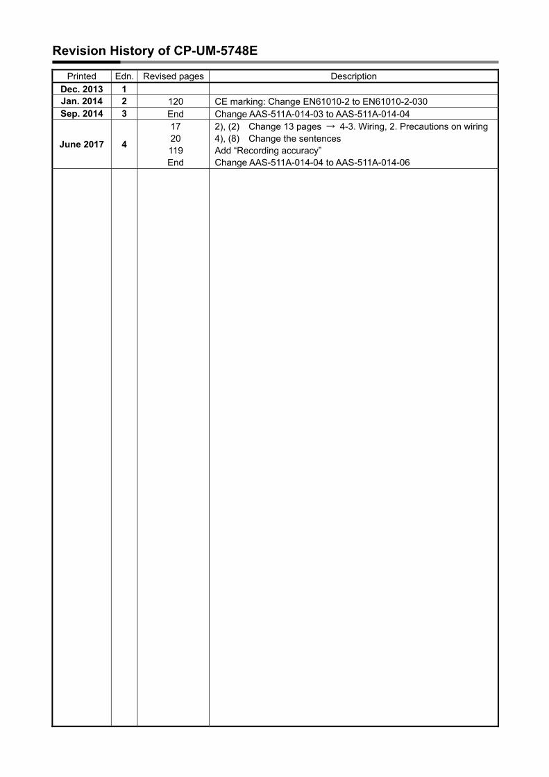
Revision History of CP-UM-5748E
Printed Edn. Revised pages Description
Dec. 2013 1 Jan. 2014 2 120 CE marking: Change EN61010-2 to EN61010-2-030 Sep. 2014 3 End Change AAS-511A-014-03 to AAS-511A-014-04
June 2017 4
17 20 119 End
2), (2) Change 13 pages → 4-3. Wiring, 2. Precautions on wiring 4), (8) Change the sentences Add “Recording accuracy” Change AAS-511A-014-04 to AAS-511A-014-06

Terms and ConditionsWe would like to express our appreciation for your purchase and use of Azbil Corporation's products. You are required to acknowledge and agree upon the following terms and conditions for your purchase of Azbil Corporation's products (system products, field instruments, control valves, and control products), unless otherwise stated in any separate document, including, without limitation, estimation sheets, written agreements, catalogs, specifications and instruction manuals.
1. Warranty period and warranty scope1.1 Warranty period
Azbil Corporation's products shall be warranted for one (1) year from the date of your purchase of the said products or the delivery of the said products to a place designated by you.
1.2 Warranty scopeIn the event that Azbil Corporation's product has any failure attributable to azbil during the aforementioned warranty period, Azbil Corporation shall, without charge, deliver a replacement for the said product to the place where you purchased, or repair the said product and deliver it to the aforementioned place. Notwithstanding the foregoing, any failure falling under one of the following shall not be covered under this warranty:
(1) Failure caused by your improper use of azbil product (noncompliance with conditions, environment of use, precautions, etc. set forth in catalogs, specifications, instruction manuals, etc.);
(2) Failure caused for other reasons than Azbil Corporation's product;(3) Failure caused by any modification or repair made by any person other than Azbil Corporation or Azbil
Corporation's subcontractors; (4) Failure caused by your use of Azbil Corporation's product in a manner not conforming to the intended usage of
that product; (5) Failure that the state-of-the-art at the time of Azbil Corporation's shipment did not allow Azbil Corporation to
predict; or (6) Failure that arose from any reason not attributable to Azbil Corporation, including, without limitation, acts of God,
disasters, and actions taken by a third party. Please note that the term “warranty” as used herein refers to equipment-only-warranty, and Azbil Corporation shall not be liable for any damages, including direct, indirect, special, incidental or consequential damages in connection with or arising out of Azbil Corporation's products.
2. Ascertainment of suitability You are required to ascertain the suitability of Azbil Corporation's product in case of your use of the same with your machinery, equipment, etc. (hereinafter referred to as “Equipment”) on your own responsibility, taking the following matters into consideration:
(1) Regulations and standards or laws that your Equipment is to comply with.(2) Examples of application described in any documents provided by Azbil Corporation are for your reference
purpose only, and you are required to check the functions and safety of your Equipment prior to your use. (3) Measures to be taken to secure the required level of the reliability and safety of your Equipment in your use
Although azbil is constantly making efforts to improve the quality and reliability of Azbil Corporation's products, there exists a possibility that parts and machinery may break down. You are required to provide your Equipment with safety design such as fool-proof design, *1 and fail-safe design*2 (anti-flame propagation design, etc.), whereby preventing any occurrence of physical injuries, fires, significant damage, and so forth. Furthermore, fault avoidance, *3 fault tolerance,*4 or the like should be incorporated so that the said Equipment can satisfy the level of reliability and safety required for your use.
*1. A design that is safe even if the user makes an error. *2. A design that is safe even if the device fails. *3. Avoidance of device failure by using highly reliable components, etc. *4. The use of redundancy.
3. Precautions and restrictions on application Azbil Corporation's products other than those explicitly specified as applicable (e.g. azbil Limit Switch For Nuclear Energy) shall not be used in a nuclear energy controlled area (radiation controlled area). Any Azbil Corporation's products shall not be used for/with medical equipment. The products are for industrial use. Do not allow general consumers to install or use any Azbil Corporation's product. However, azbil products can be incorporated into products used by general consumers. If you intend to use a product for that purpose, please contact one of our sales representatives. In addition, you are required to conduct a consultation with our sales representative and understand detail specifications, cautions for operation, and so forth by reference to catalogs, specifications, instruction manual, etc. in case that you intend to use azbil product for any purposes specified in (1) through (6) below. Moreover, you are required to provide your Equipment with fool-proof design, fail-safe design, anti-flame propagation design, fault avoidance, fault tolerance, and other kinds of protection/safety circuit design on your own responsibility to ensure reliability and safety, whereby preventing problems caused by failure or nonconformity.
(1) For use under such conditions or in such environments as not stated in technical documents, including catalogs, specification, and instruction manuals
(2) For use of specific purposes, such as: * Nuclear energy/radiation related facilities
[For use outside nuclear energy controlled areas] [For use of Azbil Corporation's Limit Switch For Nuclear Energy]
* Machinery or equipment for space/sea bottom * Transportation equipment [Railway, aircraft, vessels, vehicle equipment, etc.] * Antidisaster/crime-prevention equipment

* Burning appliances * Electrothermal equipment * Amusement facilities * Facilities/applications associated directly with billing
(3) Supply systems such as electricity/gas/water supply systems, large-scale communication systems, and traffic/air traffic control systems requiring high reliability
(4) Facilities that are to comply with regulations of governmental/public agencies or specific industries (5) Machinery or equipment that may affect human lives, human bodies or properties (6) Other machinery or equipment equivalent to those set forth in items (1) to (5) above which require high reliability
and safety
4. Precautions against long-term use Use of Azbil Corporation's products, including switches, which contain electronic components, over a prolonged period may degrade insulation or increase contact-resistance and may result in heat generation or any other similar problem causing such product or switch to develop safety hazards such as smoking, ignition, and electrification.Although acceleration of the above situation varies depending on the conditions or environment of use of the products, you are required not to use any Azbil Corporation's products for a period exceeding ten (10) years unless otherwise stated in specifications or instruction manuals.
5. Recommendation for renewalMechanical components, such as relays and switches, used for Azbil Corporation's products will reach the end of their life due to wear by repetitious open/close operations. In addition, electronic components such as electrolytic capacitors will reach the end of their life due to aged deterioration based on the conditions or environment in which such electronic components are used.Although acceleration of the above situation varies depending on the conditions or environment of use, the number of open/close operations of relays, etc. as prescribed in specifications or instruction manuals, or depending on the design margin of your machine or equipment, you are required to renew any Azbil Corporation's products every 5 to 10 years unless otherwise specified in specifications or instruction manuals.System products, field instruments (sensors such as pressure/flow/level sensors, regulating valves, etc.) will reach the end of their life due to aged deterioration of parts.For those parts that will reach the end of their life due to aged deterioration, recommended replacement cycles are prescribed. You are required to replace parts based on such recommended replacement cycles.
6. Other precautionsPrior to your use of Azbil Corporation's products, you are required to understand and comply with specifications (e.g., conditions and environment of use), precautions, warnings/cautions/notices as set forth in the technical documents prepared for individual Azbil Corporation's products, such as catalogs, specifications, and instruction manuals to ensure the quality, reliability, and safety of those products.
7. Changes to specifications Please note that the descriptions contained in any documents provided by azbil are subject to change without notice for improvement or for any other reason.For inquires or information on specifications as you may need to check, please contact our branch offices or sales offices, or your local sales agents.
8. Discontinuance of the supply of products/partsPlease note that the production of any Azbil Corporation's product may be discontinued without notice. For repairable products, we will, in principle, undertake repairs for five (5) years after the discontinuance of those products. In some cases, however, we cannot undertake such repairs for reasons, such as the absence of repair parts.For system products, field instruments, we may not be able to undertake parts replacement for similar reasons.
9. Scope of services Prices of Azbil Corporation's products do not include any charges for services such as engineer dispatch service. Accordingly, a separate fee will be charged in any of the following cases:
(1) Installation, adjustment, guidance, and attendance at a test run (2) Maintenance, inspection, adjustment, and repair(3) Technical guidance and technical education (4) Special test or special inspection of a product under the conditions specified by you
Please note that we cannot provide any services as set forth above in a nuclear energy controlled area (radiation controlled area) or at a place where the level of exposure to radiation is equivalent to that in a nuclear energy controlled area.
AAS-511A-014-06

MEMO


CHINO Corporation
32-8 KUMANO-CHO, ITABASHI-KU,
TOKYO 173-8632 JAPAN
[Manufacturer]
1st edition: Dec. 2013 (K )
4th edition: June 2017 (K )
[Selling agency]