Embed Size (px)
Citation preview
INSTRUCTION MANUAL
AQ L310 – Line protection IED

Instruction manual –AQ L310 Line Protection IED 2 (180)
Revision 1.00
Date January 2016
Changes - The first revision.
Read these instructions carefully and inspect the equipment to become familiar with it
before trying to install, operate, service or maintain it.
Electrical equipment should be installed, operated, serviced, and maintained only by
qualified personnel. Local safety regulations should be followed. No responsibility is
assumed by Arcteq for any consequences arising out of the use of this material.
We reserve right to changes without further notice.
Instruction manual –AQ L310 Line Protection IED 3 (180)
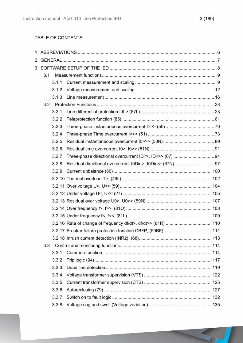
TABLE OF CONTENTS
1 ABBREVIATIONS ............................................................................................................. 6
2 GENERAL ......................................................................................................................... 7
3 SOFTWARE SETUP OF THE IED .................................................................................... 8
3.1 Measurement functions .......................................................................................... 9
3.1.1 Current measurement and scaling ................................................................ 9
3.1.2 Voltage measurement and scaling .............................................................. 12
3.1.3 Line measurement ...................................................................................... 16
3.2 Protection Functions ............................................................................................ 23
3.2.1 Line differential protection IdL> (87L) .......................................................... 23
3.2.2 Teleprotection function (85) ........................................................................ 61
3.2.3 Three-phase instantaneous overcurrent I>>> (50) ...................................... 70
3.2.4 Three-phase Time overcurrent I>>> (51) .................................................... 73
3.2.5 Residual instantaneous overcurrent I0>>> (50N) ........................................ 89
3.2.6 Residual time overcurrent I0>, I0>> (51N) .................................................. 91
3.2.7 Three-phase directional overcurrent IDir>, IDir>> (67) ................................ 94
3.2.8 Residual directional overcurrent I0Dir >, I0Dir>> (67N) ............................... 97
3.2.9 Current unbalance (60) ............................................................................. 100
3.2.10 Thermal overload T>, (49L) ...................................................................... 102
3.2.11 Over voltage U>, U>> (59) ........................................................................ 104
3.2.12 Under voltage U<, U<< (27) ...................................................................... 105
3.2.13 Residual over voltage U0>, U0>> (59N) ................................................... 107
3.2.14 Over frequency f>, f>>, (81O) ................................................................... 108
3.2.15 Under frequency f<, f<<, (81L) .................................................................. 109
3.2.16 Rate of change of frequency df/dt>, df/dt>> (81R) .................................... 110
3.2.17 Breaker failure protection function CBFP, (50BF) ..................................... 111
3.2.18 Inrush current detection (INR2), (68) ......................................................... 113
3.3 Control and monitoring functions ........................................................................ 114
3.3.1 Common-function ..................................................................................... 114
3.3.2 Trip logic (94) ............................................................................................ 117
3.3.3 Dead line detection ................................................................................... 119
3.3.4 Voltage transformer supervision (VTS) ..................................................... 122
3.3.5 Current transformer supervision (CTS) ..................................................... 125
3.3.6 Autoreclosing (79) ..................................................................................... 127
3.3.7 Switch on to fault logic .............................................................................. 132
3.3.8 Voltage sag and swell (Voltage variation) ................................................. 135
Instruction manual –AQ L310 Line Protection IED 4 (180)
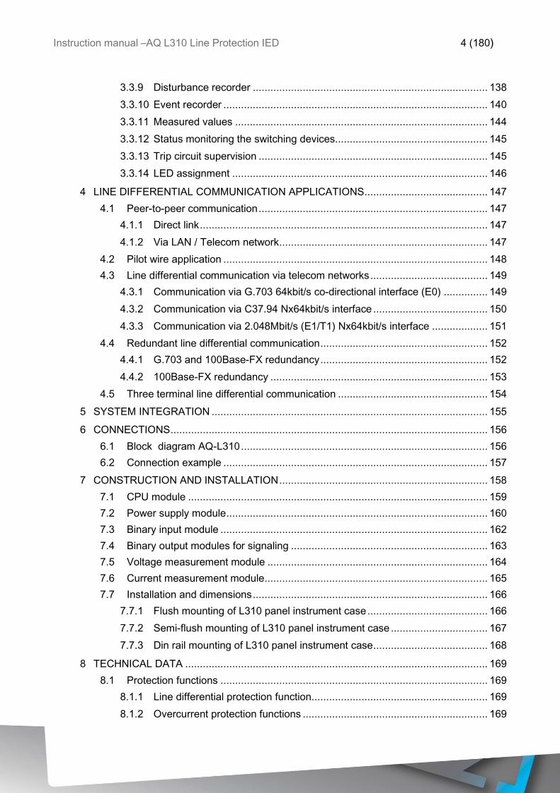
3.3.9 Disturbance recorder ................................................................................ 138
3.3.10 Event recorder .......................................................................................... 140
3.3.11 Measured values ...................................................................................... 144
3.3.12 Status monitoring the switching devices .................................................... 145
3.3.13 Trip circuit supervision .............................................................................. 145
3.3.14 LED assignment ....................................................................................... 146
4 LINE DIFFERENTIAL COMMUNICATION APPLICATIONS .......................................... 147
4.1 Peer-to-peer communication .............................................................................. 147
4.1.1 Direct link .................................................................................................. 147
4.1.2 Via LAN / Telecom network ....................................................................... 147
4.2 Pilot wire application .......................................................................................... 148
4.3 Line differential communication via telecom networks ........................................ 149
4.3.1 Communication via G.703 64kbit/s co-directional interface (E0) ............... 149
4.3.2 Communication via C37.94 Nx64kbit/s interface ....................................... 150
4.3.3 Communication via 2.048Mbit/s (E1/T1) Nx64kbit/s interface ................... 151
4.4 Redundant line differential communication ......................................................... 152
4.4.1 G.703 and 100Base-FX redundancy ......................................................... 152
4.4.2 100Base-FX redundancy .......................................................................... 153
4.5 Three terminal line differential communication ................................................... 154
5 SYSTEM INTEGRATION .............................................................................................. 155
6 CONNECTIONS ............................................................................................................ 156
6.1 Block diagram AQ-L310 .................................................................................... 156
6.2 Connection example .......................................................................................... 157
7 CONSTRUCTION AND INSTALLATION ....................................................................... 158
7.1 CPU module ...................................................................................................... 159
7.2 Power supply module ......................................................................................... 160
7.3 Binary input module ........................................................................................... 162
7.4 Binary output modules for signaling ................................................................... 163
7.5 Voltage measurement module ........................................................................... 164
7.6 Current measurement module ............................................................................ 165
7.7 Installation and dimensions ................................................................................ 166
7.7.1 Flush mounting of L310 panel instrument case ......................................... 166
7.7.2 Semi-flush mounting of L310 panel instrument case ................................. 167
7.7.3 Din rail mounting of L310 panel instrument case ....................................... 168
8 TECHNICAL DATA ....................................................................................................... 169
8.1 Protection functions ........................................................................................... 169
8.1.1 Line differential protection function ............................................................ 169
8.1.2 Overcurrent protection functions ............................................................... 169
Instruction manual –AQ L310 Line Protection IED 5 (180)
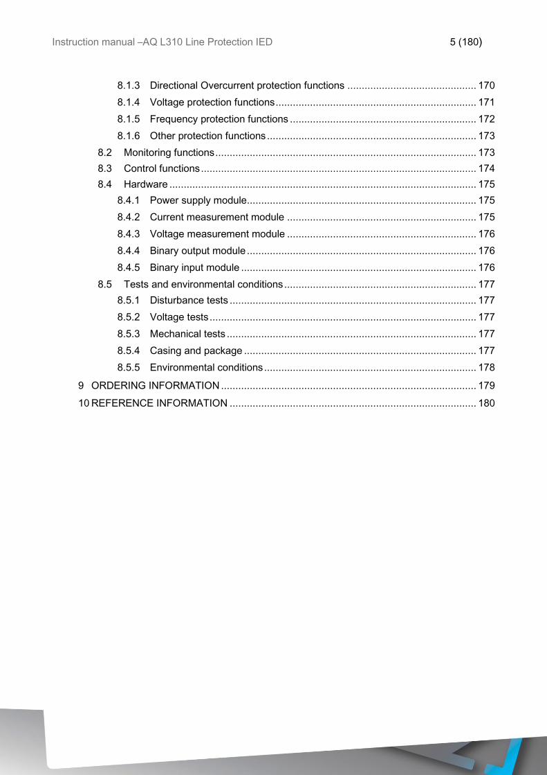
8.1.3 Directional Overcurrent protection functions ............................................. 170
8.1.4 Voltage protection functions ...................................................................... 171
8.1.5 Frequency protection functions ................................................................. 172
8.1.6 Other protection functions ......................................................................... 173
8.2 Monitoring functions ........................................................................................... 173
8.3 Control functions ................................................................................................ 174
8.4 Hardware ........................................................................................................... 175
8.4.1 Power supply module ................................................................................ 175
8.4.2 Current measurement module .................................................................. 175
8.4.3 Voltage measurement module .................................................................. 176
8.4.4 Binary output module ................................................................................ 176
8.4.5 Binary input module .................................................................................. 176
8.5 Tests and environmental conditions ................................................................... 177
8.5.1 Disturbance tests ...................................................................................... 177
8.5.2 Voltage tests ............................................................................................. 177
8.5.3 Mechanical tests ....................................................................................... 177
8.5.4 Casing and package ................................................................................. 177
8.5.5 Environmental conditions .......................................................................... 178
9 ORDERING INFORMATION ......................................................................................... 179
10 REFERENCE INFORMATION ...................................................................................... 180

Instruction manual –AQ L310 Line Protection IED 6 (180)
1 ABBREVIATIONS
CB – Circuit breaker
CBFP – Circuit breaker failure protection
CT – Current transformer
CPU – Central processing unit
EMC – Electromagnetic compatibility
HMI – Human machine interface
HW – Hardware
IED – Intelligent electronic device
IO – Input output
LED – Light emitting diode
LV – Low voltage
MV – Medium voltage
NC – Normally closed
NO – Normally open
RMS – Root mean square
SF – System failure
TMS – Time multiplier setting
TRMS – True root mean square
VAC – Voltage alternating current
VDC – Voltage direct current
SW – Software
uP - Microprocessor

Instruction manual –AQ L310 Line Protection IED 7 (180)
2 GENERAL
The AQ-L310 line protection IED is a member of the AQ-300 product line. The AQ-300
protection product line in respect of hardware and software is a modular device. The
hardware modules are assembled and configured according to the application IO
requirements and the software determines the available functions. This manual describes
the specific application of the AQ-L310 line protection IED.
Instruction manual –AQ L310 Line Protection IED 8 (180)
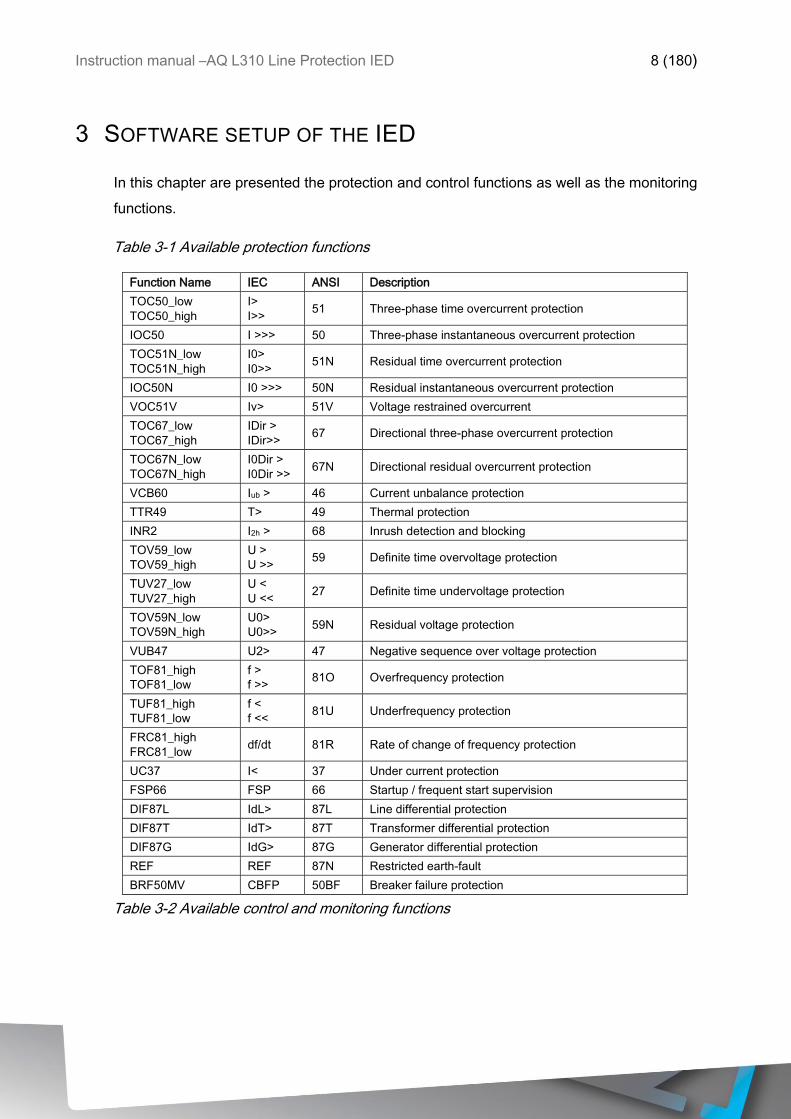
3 SOFTWARE SETUP OF THE IED
In this chapter are presented the protection and control functions as well as the monitoring
functions.
Table 3-1 Available protection functions
Function Name IEC ANSI Description
TOC50_low
TOC50_high
I>
I>> 51 Three-phase time overcurrent protection
IOC50 I >>> 50 Three-phase instantaneous overcurrent protection
TOC51N_low
TOC51N_high
I0>
I0>> 51N Residual time overcurrent protection
IOC50N I0 >>> 50N Residual instantaneous overcurrent protection
VOC51V Iv> 51V Voltage restrained overcurrent
TOC67_low
TOC67_high
IDir >
IDir>> 67 Directional three-phase overcurrent protection
TOC67N_low
TOC67N_high
I0Dir >
I0Dir >> 67N Directional residual overcurrent protection
VCB60 Iub > 46 Current unbalance protection
TTR49 T> 49 Thermal protection
INR2 I2h > 68 Inrush detection and blocking
TOV59_low
TOV59_high
U >
U >> 59 Definite time overvoltage protection
TUV27_low
TUV27_high
U <
U << 27 Definite time undervoltage protection
TOV59N_low
TOV59N_high
U0>
U0>> 59N Residual voltage protection
VUB47 U2> 47 Negative sequence over voltage protection
TOF81_high
TOF81_low
f >
f >> 81O Overfrequency protection
TUF81_high
TUF81_low
f <
f << 81U Underfrequency protection
FRC81_high
FRC81_low df/dt 81R Rate of change of frequency protection
UC37 I< 37 Under current protection
FSP66 FSP 66 Startup / frequent start supervision
DIF87L IdL> 87L Line differential protection
DIF87T IdT> 87T Transformer differential protection
DIF87G IdG> 87G Generator differential protection
REF REF 87N Restricted earth-fault
BRF50MV CBFP 50BF Breaker failure protection
Table 3-2 Available control and monitoring functions
Instruction manual –AQ L310 Line Protection IED 9 (180)
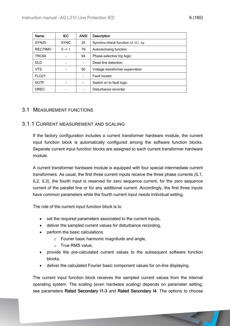
Name IEC ANSI Description
SYN25 SYNC 25 Synchro-check function Δf, ΔU, Δφ
REC79MV 0 -> 1 79 Autoreclosing function
TRC94 - 94 Phase-selective trip logic
DLD - - Dead line detection
VTS - 60 Voltage transformer supervision
FLO21 - Fault locator
SOTF - - Switch on to fault logic
DREC - - Disturbance recorder
3.1 MEASUREMENT FUNCTIONS
3.1.1 CURRENT MEASUREMENT AND SCALING
If the factory configuration includes a current transformer hardware module, the current
input function block is automatically configured among the software function blocks.
Separate current input function blocks are assigned to each current transformer hardware
module.
A current transformer hardware module is equipped with four special intermediate current
transformers. As usual, the first three current inputs receive the three phase currents (IL1,
IL2, IL3), the fourth input is reserved for zero sequence current, for the zero sequence
current of the parallel line or for any additional current. Accordingly, the first three inputs
have common parameters while the fourth current input needs individual setting.
The role of the current input function block is to
set the required parameters associated to the current inputs,
deliver the sampled current values for disturbance recording,
perform the basic calculations
o Fourier basic harmonic magnitude and angle,
o True RMS value;
provide the pre-calculated current values to the subsequent software function
blocks,
deliver the calculated Fourier basic component values for on-line displaying.
The current input function block receives the sampled current values from the internal
operating system. The scaling (even hardware scaling) depends on parameter setting,
see parameters Rated Secondary I1-3 and Rated Secondary I4. The options to choose
Instruction manual –AQ L310 Line Protection IED 10 (180)
from are 1A or 5A (in special applications, 0.2A or 1A). This parameter influences the
internal number format and, naturally, accuracy. A small current is processed with finer
resolution if 1A is selected.
If needed, the phase currents can be inverted by setting the parameter Starpoint I1-3. This
selection applies to each of the channels IL1, IL2 and IL3. The fourth current channel can
be inverted by setting the parameter Direction I4. This inversion may be needed in
protection functions such as distance protection, differential protection or for any functions
with directional decision.
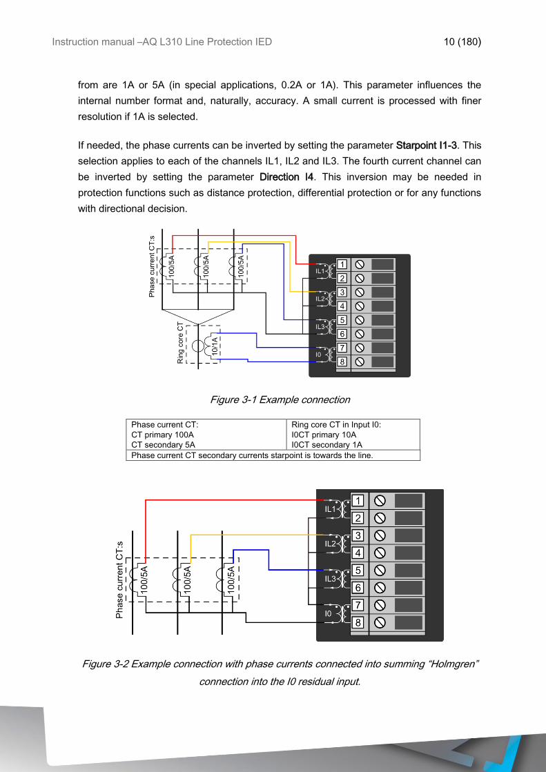
Figure 3-1 Example connection
Phase current CT:
CT primary 100A
CT secondary 5A
Ring core CT in Input I0:
I0CT primary 10A
I0CT secondary 1A
Phase current CT secondary currents starpoint is towards the line.
Figure 3-2 Example connection with phase currents connected into summing “Holmgren”
connection into the I0 residual input.
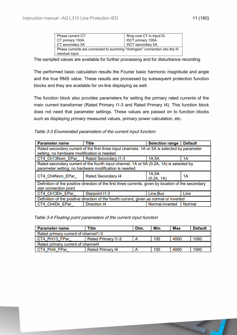
Instruction manual –AQ L310 Line Protection IED 11 (180)
Phase current CT:
CT primary 100A
CT secondary 5A
Ring core CT in Input I0:
I0CT primary 100A
I0CT secondary 5A
Phase currents are connected to summing “Holmgren” connection into the I0
residual input.
The sampled values are available for further processing and for disturbance recording.
The performed basic calculation results the Fourier basic harmonic magnitude and angle
and the true RMS value. These results are processed by subsequent protection function
blocks and they are available for on-line displaying as well.
The function block also provides parameters for setting the primary rated currents of the
main current transformer (Rated Primary I1-3 and Rated Primary I4). This function block
does not need that parameter settings. These values are passed on to function blocks
such as displaying primary measured values, primary power calculation, etc.
Table 3-3 Enumerated parameters of the current input function
Table 3-4 Floating point parameters of the current input function
Instruction manual –AQ L310 Line Protection IED 12 (180)
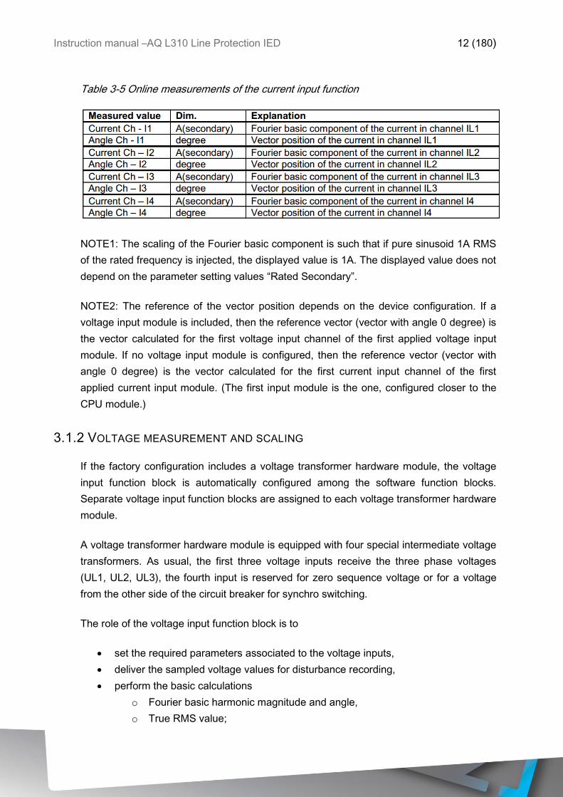
Table 3-5 Online measurements of the current input function
NOTE1: The scaling of the Fourier basic component is such that if pure sinusoid 1A RMS
of the rated frequency is injected, the displayed value is 1A. The displayed value does not
depend on the parameter setting values “Rated Secondary”.
NOTE2: The reference of the vector position depends on the device configuration. If a
voltage input module is included, then the reference vector (vector with angle 0 degree) is
the vector calculated for the first voltage input channel of the first applied voltage input
module. If no voltage input module is configured, then the reference vector (vector with
angle 0 degree) is the vector calculated for the first current input channel of the first
applied current input module. (The first input module is the one, configured closer to the
CPU module.)
3.1.2 VOLTAGE MEASUREMENT AND SCALING
If the factory configuration includes a voltage transformer hardware module, the voltage
input function block is automatically configured among the software function blocks.
Separate voltage input function blocks are assigned to each voltage transformer hardware
module.
A voltage transformer hardware module is equipped with four special intermediate voltage
transformers. As usual, the first three voltage inputs receive the three phase voltages
(UL1, UL2, UL3), the fourth input is reserved for zero sequence voltage or for a voltage
from the other side of the circuit breaker for synchro switching.
The role of the voltage input function block is to
set the required parameters associated to the voltage inputs,
deliver the sampled voltage values for disturbance recording,
perform the basic calculations
o Fourier basic harmonic magnitude and angle,
o True RMS value;
Instruction manual –AQ L310 Line Protection IED 13 (180)
provide the pre-calculated voltage values to the subsequent software modules,
deliver the calculated basic Fourier component values for on-line displaying.
The voltage input function block receives the sampled voltage values from the internal
operating system. The scaling (even hardware scaling) depends on a common parameter
“Range” for type selection. The options to choose from are 100V or 200V, no hardware
modification is needed. A small voltage is processed with finer resolution if 100V is
selected. This parameter influences the internal number format and, naturally, accuracy.
There is a correction factor available if the rated secondary voltage of the main voltage
transformer (e.g. 110V) does not match the rated input of the device. The related
parameter is “VT correction“. As an example: if the rated secondary voltage of the main
voltage transformer is 110V, then select Type 100 for the parameter “Range” and the
required value to set here is 110%.
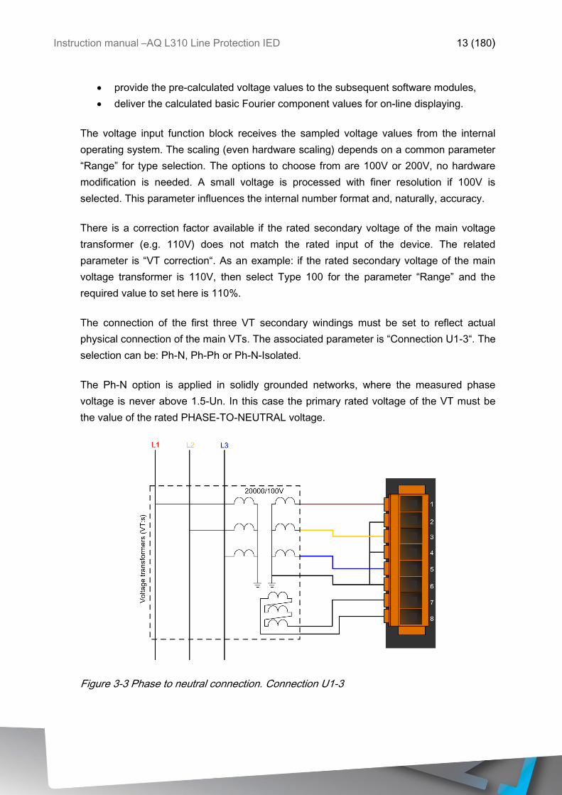
The connection of the first three VT secondary windings must be set to reflect actual
physical connection of the main VTs. The associated parameter is “Connection U1-3“. The
selection can be: Ph-N, Ph-Ph or Ph-N-Isolated.
The Ph-N option is applied in solidly grounded networks, where the measured phase
voltage is never above 1.5-Un. In this case the primary rated voltage of the VT must be
the value of the rated PHASE-TO-NEUTRAL voltage.
Figure 3-3 Phase to neutral connection. Connection U1-3
Instruction manual –AQ L310 Line Protection IED 14 (180)
Ph-N Voltage:
Rated Primary U1-3: 11.55kV (=20kv/√3)
Range: Type 100
Residual voltage:
Rated Primary U4: 11.54A
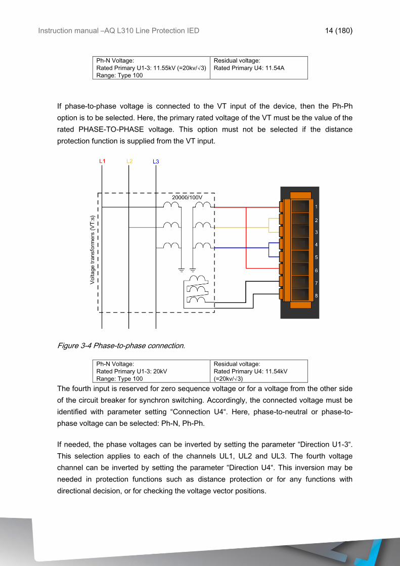
If phase-to-phase voltage is connected to the VT input of the device, then the Ph-Ph
option is to be selected. Here, the primary rated voltage of the VT must be the value of the
rated PHASE-TO-PHASE voltage. This option must not be selected if the distance
protection function is supplied from the VT input.
Figure 3-4 Phase-to-phase connection.
Ph-N Voltage:
Rated Primary U1-3: 20kV
Range: Type 100
Residual voltage:
Rated Primary U4: 11.54kV
(=20kv/√3)
The fourth input is reserved for zero sequence voltage or for a voltage from the other side
of the circuit breaker for synchron switching. Accordingly, the connected voltage must be
identified with parameter setting “Connection U4“. Here, phase-to-neutral or phase-to-
phase voltage can be selected: Ph-N, Ph-Ph.
If needed, the phase voltages can be inverted by setting the parameter “Direction U1-3“.
This selection applies to each of the channels UL1, UL2 and UL3. The fourth voltage
channel can be inverted by setting the parameter “Direction U4“. This inversion may be
needed in protection functions such as distance protection or for any functions with
directional decision, or for checking the voltage vector positions.
Instruction manual –AQ L310 Line Protection IED 15 (180)
These modified sampled values are available for further processing and for disturbance
recording.
The function block also provides parameters for setting the primary rated voltages of the
main voltage transformers. This function block does not need that parameter setting but
these values are passed on to function blocks such as displaying primary measured
values, primary power calculation, etc.
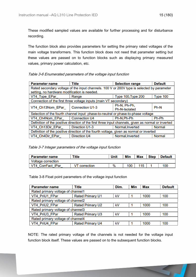
Table 3-6 Enumerated parameters of the voltage input function
Table 3-7 Integer parameters of the voltage input function
Table 3-8 Float point parameters of the voltage input function
NOTE: The rated primary voltage of the channels is not needed for the voltage input
function block itself. These values are passed on to the subsequent function blocks.
Instruction manual –AQ L310 Line Protection IED 16 (180)
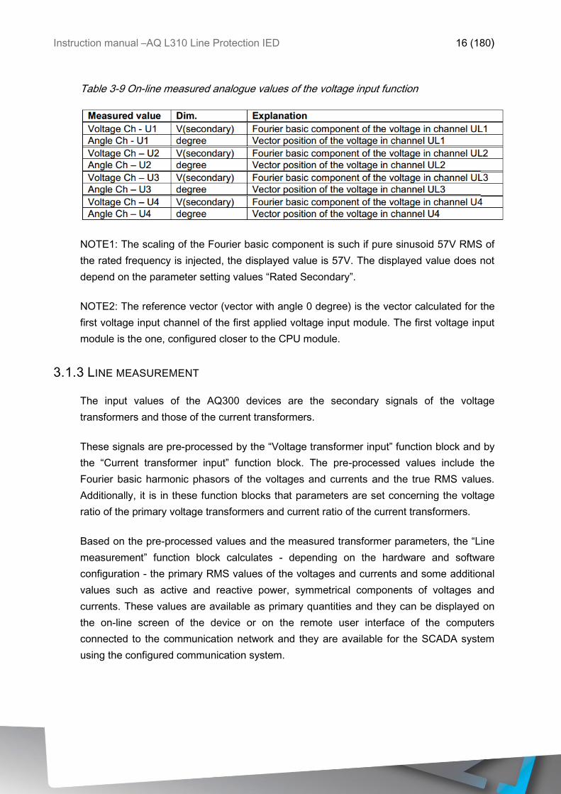
Table 3-9 On-line measured analogue values of the voltage input function
NOTE1: The scaling of the Fourier basic component is such if pure sinusoid 57V RMS of
the rated frequency is injected, the displayed value is 57V. The displayed value does not
depend on the parameter setting values “Rated Secondary”.
NOTE2: The reference vector (vector with angle 0 degree) is the vector calculated for the
first voltage input channel of the first applied voltage input module. The first voltage input
module is the one, configured closer to the CPU module.
3.1.3 LINE MEASUREMENT
The input values of the AQ300 devices are the secondary signals of the voltage
transformers and those of the current transformers.
These signals are pre-processed by the “Voltage transformer input” function block and by
the “Current transformer input” function block. The pre-processed values include the
Fourier basic harmonic phasors of the voltages and currents and the true RMS values.
Additionally, it is in these function blocks that parameters are set concerning the voltage
ratio of the primary voltage transformers and current ratio of the current transformers.
Based on the pre-processed values and the measured transformer parameters, the “Line
measurement” function block calculates - depending on the hardware and software
configuration - the primary RMS values of the voltages and currents and some additional
values such as active and reactive power, symmetrical components of voltages and
currents. These values are available as primary quantities and they can be displayed on
the on-line screen of the device or on the remote user interface of the computers
connected to the communication network and they are available for the SCADA system
using the configured communication system.

Instruction manual –AQ L310 Line Protection IED 17 (180)
3.1.3.1 Reporting the measured values and the changes
It is usual for the SCADA systems that they sample the measured and calculated values
in regular time periods and additionally they receive the changed values as reports at the
moment when any significant change is detected in the primary system. The “Line
measurement” function block is able to perform such reporting for the SCADA system.
3.1.3.2 Operation of the line measurement function block
The inputs of the line measurement function are
the Fourier components and true RMS values of the measured voltages and
currents
frequency measurement
parameters.
The outputs of the line measurement function are
displayed measured values
reports to the SCADA system.
NOTE: the scaling values are entered as parameter setting for the “Voltage transformer
input” function block and for the “Current transformer input” function block.
3.1.3.3 Measured values
The measured values of the line measurement function depend on the hardware
configuration. As an example, table shows the list of the measured values available in a
configuration for solidly grounded networks.
Instruction manual –AQ L310 Line Protection IED 18 (180)
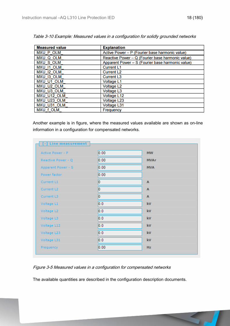
Table 3-10 Example: Measured values in a configuration for solidly grounded networks
Another example is in figure, where the measured values available are shown as on-line
information in a configuration for compensated networks.
Figure 3-5 Measured values in a configuration for compensated networks
The available quantities are described in the configuration description documents.

Instruction manual –AQ L310 Line Protection IED 19 (180)
3.1.3.4 Reporting the measured values and the changes
For reporting, additional information is needed, which is defined in parameter setting. As
an example, in a configuration for solidly grounded networks the following parameters are
available:
Table 3-11 The enumerated parameters of the line measurement function.
The selection of the reporting mode items is explained in next chapters.
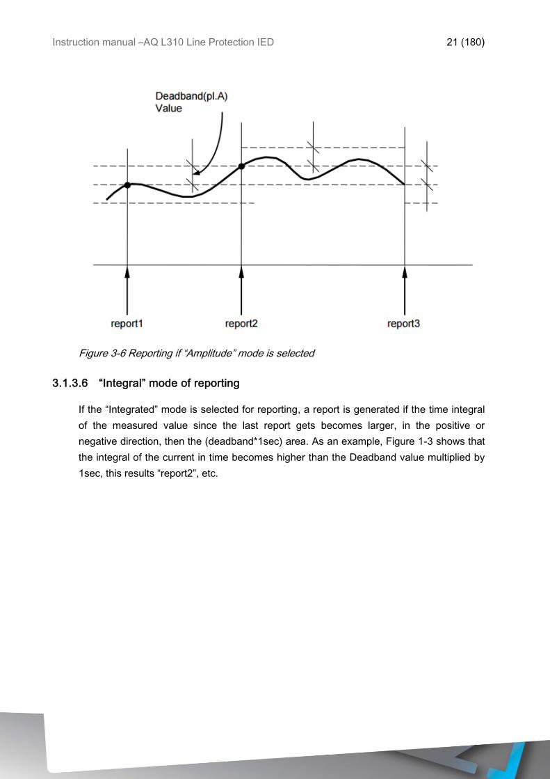
3.1.3.5 “Amplitude” mode of reporting
If the “Amplitude” mode is selected for reporting, a report is generated if the measured
value leaves the deadband around the previously reported value. As an example, Figure
1-2 shows that the current becomes higher than the value reported in “report1” PLUS the
Deadband value, this results “report2”, etc.
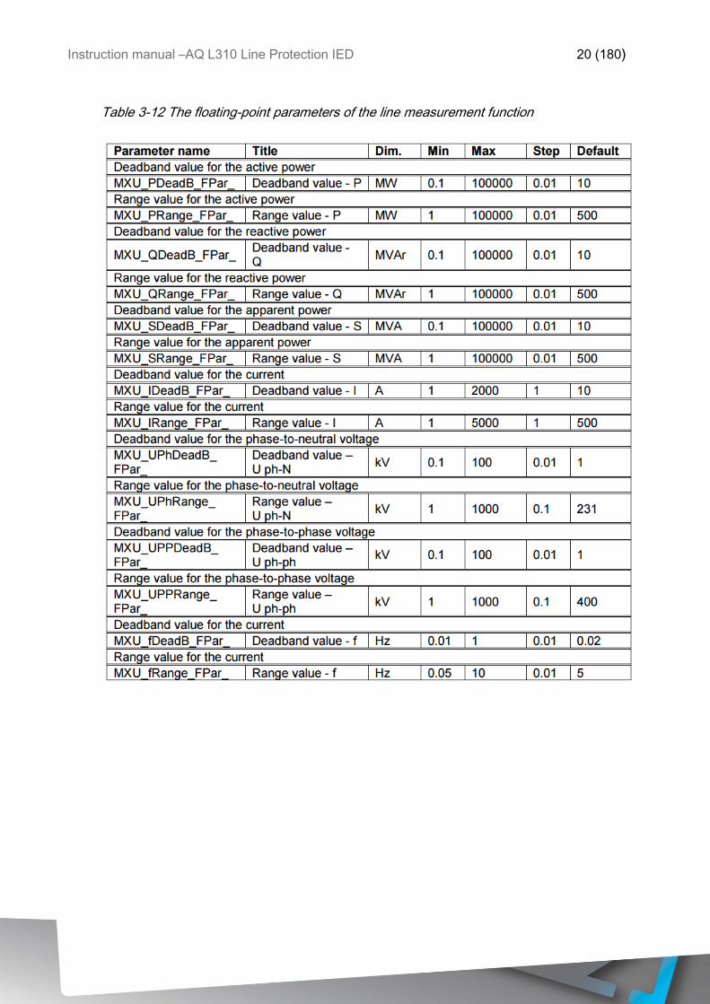
For this mode of operation, the Deadband parameters are explained in table below.
The “Range” parameters in the table are needed to evaluate a measurement as “out-of-
range”.
Instruction manual –AQ L310 Line Protection IED 20 (180)
Table 3-12 The floating-point parameters of the line measurement function
Instruction manual –AQ L310 Line Protection IED 21 (180)
Figure 3-6 Reporting if “Amplitude” mode is selected
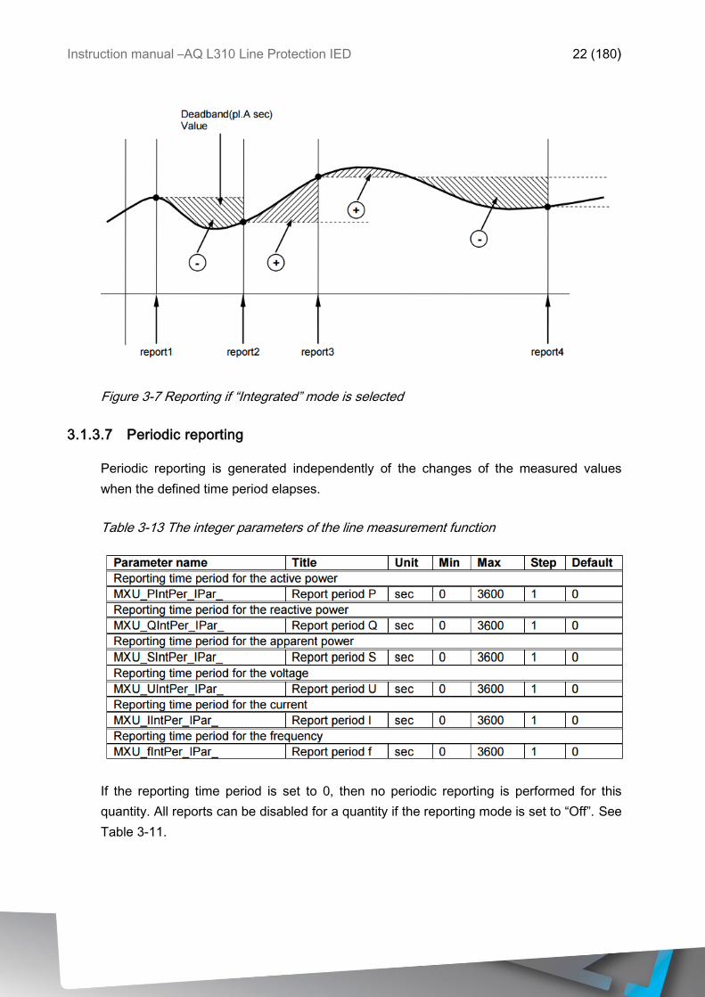
3.1.3.6 “Integral” mode of reporting
If the “Integrated” mode is selected for reporting, a report is generated if the time integral
of the measured value since the last report gets becomes larger, in the positive or
negative direction, then the (deadband*1sec) area. As an example, Figure 1-3 shows that
the integral of the current in time becomes higher than the Deadband value multiplied by
1sec, this results “report2”, etc.
Instruction manual –AQ L310 Line Protection IED 22 (180)
Figure 3-7 Reporting if “Integrated” mode is selected
3.1.3.7 Periodic reporting
Periodic reporting is generated independently of the changes of the measured values
when the defined time period elapses.
Table 3-13 The integer parameters of the line measurement function
If the reporting time period is set to 0, then no periodic reporting is performed for this
quantity. All reports can be disabled for a quantity if the reporting mode is set to “Off”. See
Table 3-11.
Instruction manual –AQ L310 Line Protection IED 23 (180)
3.2 PROTECTION FUNCTIONS
3.2.1 LINE DIFFERENTIAL PROTECTION IDL> (87L)
The AQ 300 series has two kinds of line differential algorithms available, one with
transformer in the protected zone and one without. The type of the protection function has
to be specified when ordering, for more details refer to ordering information of the IED.
Line differential function without transformer in protected zone
The line differential protection function provides main protection for two terminal
transmission lines. The line differential protection function does not apply vector shift
compensation, thus transformers must be excluded from the protected section.
The operating principle is based on synchronized Fourier basic harmonic comparison
between the line ends.
The devices at both line ends sample the phase currents and calculate the Fourier basic
harmonic components. These components are exchanged between the devices
synchronized via communication channels. The differential characteristic is a biased
characteristic with two break points. Additionally, an unbiased overcurrent stage is
applied, based on the calculated differential current.
The AQ 300 series protection IEDs communicate via fiber optic cables. Generally, mono-
mode cables are required, but for distances below 2 km a multi-mode cable may be
sufficient. The line differential protection can be applied up to the distance of 120 km. (The
limiting factor is the damping of the fiber optic channel: up to 30 dB is permitted to prevent
the disturbance of operation.)
The hardware module applied is the CPU module of the AQ 300 series protection IED.
The two devices are interconnected via the “process bus”.
Instruction manual –AQ L310 Line Protection IED 24 (180)
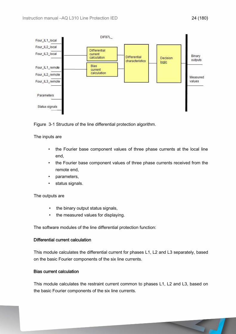
Figure 3-1 Structure of the line differential protection algorithm.
The inputs are
• the Fourier base component values of three phase currents at the local line
end,
• the Fourier base component values of three phase currents received from the
remote end,
• parameters,
• status signals.
The outputs are
• the binary output status signals,
• the measured values for displaying.
The software modules of the line differential protection function:
Differential current calculation
This module calculates the differential current for phases L1, L2 and L3 separately, based
on the basic Fourier components of the six line currents.
Bias current calculation
This module calculates the restraint current common to phases L1, L2 and L3, based on
the basic Fourier components of the six line currents.
Instruction manual –AQ L310 Line Protection IED 25 (180)
Differential characteristics
This module compares the points defined by the differential currents in phases L1, L2 and
L3 separately and the restraint current with the differential characteristic, defined by
parameter setting. The high-speed overcurrent protection function based on the line
differential currents is also performed in this module.
Decision logic
The decision logic module decides if a general trip command is to be generated.
The following description explains the details of the individual components.
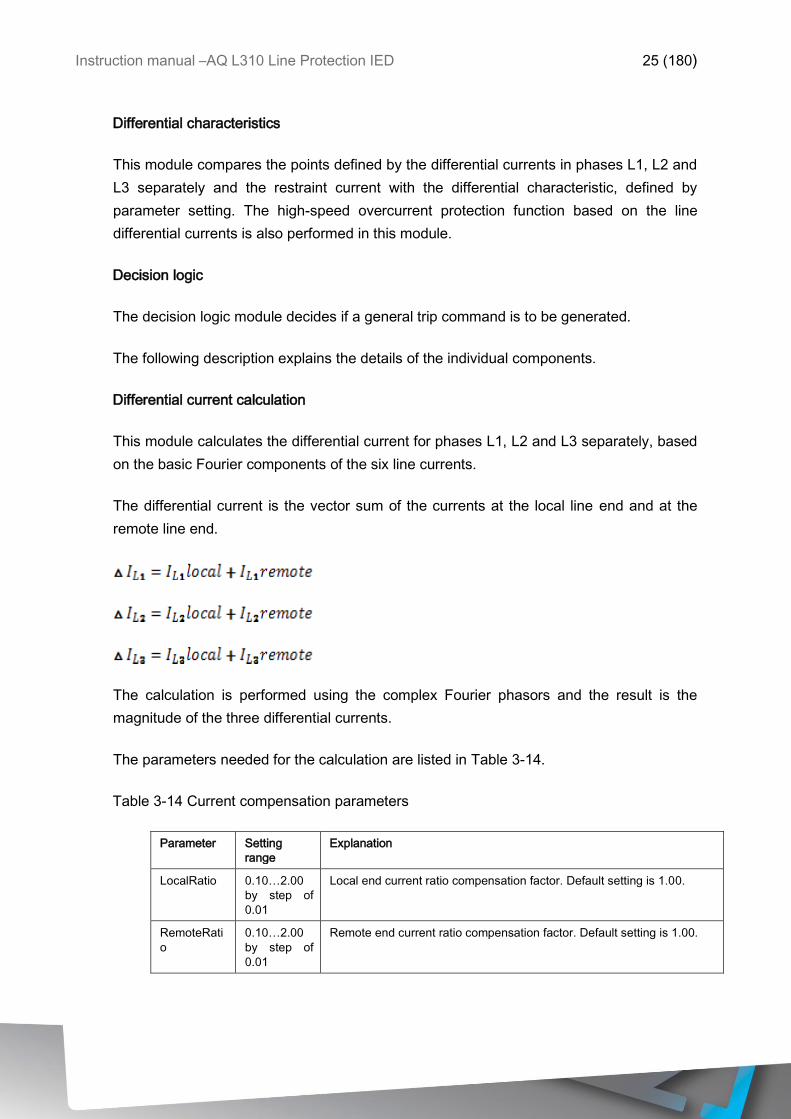
Differential current calculation
This module calculates the differential current for phases L1, L2 and L3 separately, based
on the basic Fourier components of the six line currents.
The differential current is the vector sum of the currents at the local line end and at the
remote line end.
The calculation is performed using the complex Fourier phasors and the result is the
magnitude of the three differential currents.
The parameters needed for the calculation are listed in Table 3-14.
Table 3-14 Current compensation parameters
Parameter Setting
range
Explanation
LocalRatio 0.10…2.00
by step of
0.01
Local end current ratio compensation factor. Default setting is 1.00.
RemoteRati
o
0.10…2.00
by step of
0.01
Remote end current ratio compensation factor. Default setting is 1.00.
Instruction manual –AQ L310 Line Protection IED 26 (180)
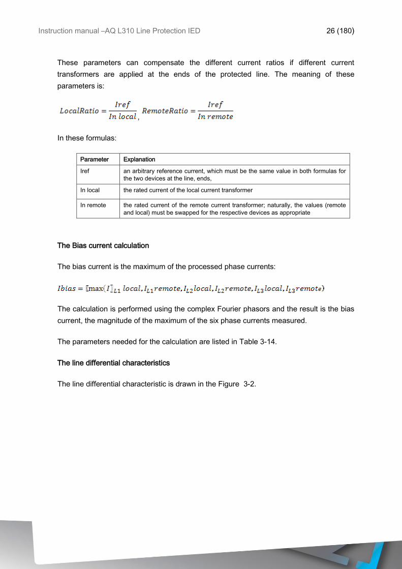
These parameters can compensate the different current ratios if different current
transformers are applied at the ends of the protected line. The meaning of these
parameters is:
,
In these formulas:
Parameter Explanation
Iref an arbitrary reference current, which must be the same value in both formulas for
the two devices at the line, ends,
In local the rated current of the local current transformer
In remote the rated current of the remote current transformer; naturally, the values (remote
and local) must be swapped for the respective devices as appropriate
The Bias current calculation
The bias current is the maximum of the processed phase currents:
The calculation is performed using the complex Fourier phasors and the result is the bias
current, the magnitude of the maximum of the six phase currents measured.
The parameters needed for the calculation are listed in Table 3-14.
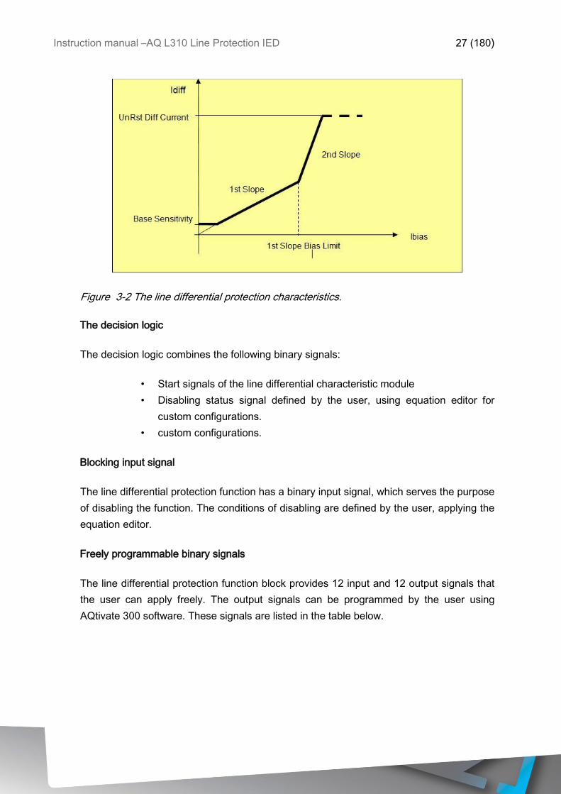
The line differential characteristics
The line differential characteristic is drawn in the Figure 3-2.
Instruction manual –AQ L310 Line Protection IED 27 (180)
Figure 3-2 The line differential protection characteristics.
The decision logic
The decision logic combines the following binary signals:
• Start signals of the line differential characteristic module
• Disabling status signal defined by the user, using equation editor for
custom configurations.
• custom configurations.
Blocking input signal
The line differential protection function has a binary input signal, which serves the purpose
of disabling the function. The conditions of disabling are defined by the user, applying the
equation editor.
Freely programmable binary signals
The line differential protection function block provides 12 input and 12 output signals that
the user can apply freely. The output signals can be programmed by the user using
AQtivate 300 software. These signals are listed in the table below.
Instruction manual –AQ L310 Line Protection IED 28 (180)
Table 3-15 Freely programmable binary signals.
Parameter Explanation
SendCh01..
Ch12
Free configurable signals to be sent via communication channel
Received
Ch01..Ch12
Free configurable signals received via communication channel
Behavior in case of communication errors
In case of communication errors concerning single data, the line differential protection
function is tolerant. Repeated errors are recognized and the function is disabled. This fact
is signaled by the “CommFail” output signal.
In error state, if healthy signals are resumed, then the system restarts operation
automatically.
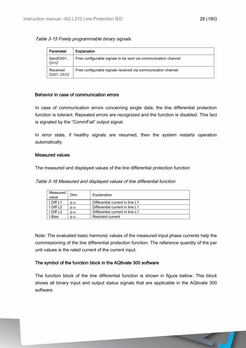
Measured values
The measured and displayed values of the line differential protection function
Table 3-16 Measured and displayed values of line differential function
Measured
value Dim. Explanation
I Diff L1 p.u. Differential current in line L1
I Diff L2 p.u. Differential current in line L1
I Diff L3 p.u. Differential current in line L1
I Bias p.u. Restraint current
Note: The evaluated basic harmonic values of the measured input phase currents help the
commissioning of the line differential protection function. The reference quantity of the per
unit values is the rated current of the current input.
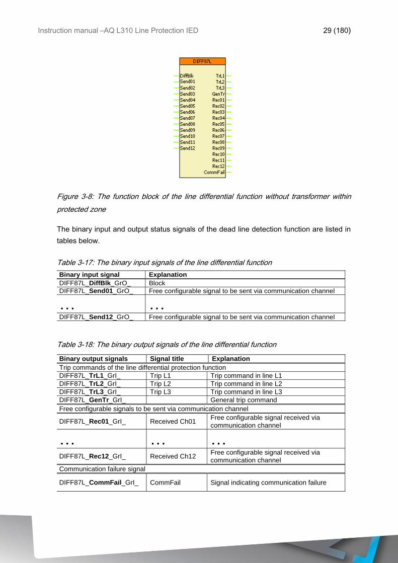
The symbol of the function block in the AQtivate 300 software
The function block of the line differential function is shown in figure bellow. This block
shows all binary input and output status signals that are applicable in the AQtivate 300
software.
Instruction manual –AQ L310 Line Protection IED 29 (180)
Figure 3-8: The function block of the line differential function without transformer within
protected zone
The binary input and output status signals of the dead line detection function are listed in
tables below.
Table 3-17: The binary input signals of the line differential function
Binary input signal Explanation
DIFF87L_DiffBlk_GrO_ Block
DIFF87L_Send01_GrO_ Free configurable signal to be sent via communication channel
… …
DIFF87L_Send12_GrO_ Free configurable signal to be sent via communication channel
Table 3-18: The binary output signals of the line differential function
Binary output signals Signal title Explanation
Trip commands of the line differential protection function
DIFF87L_TrL1_GrI_ Trip L1 Trip command in line L1
DIFF87L_TrL2_GrI_ Trip L2 Trip command in line L2
DIFF87L_TrL3_GrI_ Trip L3 Trip command in line L3
DIFF87L_GenTr_GrI_ General trip command
Free configurable signals to be sent via communication channel
DIFF87L_Rec01_GrI_ Received Ch01 Free configurable signal received via communication channel
… … …
DIFF87L_Rec12_GrI_ Received Ch12 Free configurable signal received via communication channel
Communication failure signal
DIFF87L_CommFail_GrI_ CommFail Signal indicating communication failure
Instruction manual –AQ L310 Line Protection IED 30 (180)
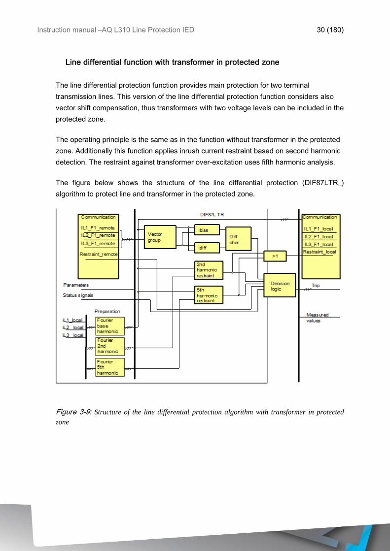
Line differential function with transformer in protected zone
The line differential protection function provides main protection for two terminal
transmission lines. This version of the line differential protection function considers also
vector shift compensation, thus transformers with two voltage levels can be included in the
protected zone.
The operating principle is the same as in the function without transformer in the protected
zone. Additionally this function applies inrush current restraint based on second harmonic
detection. The restraint against transformer over-excitation uses fifth harmonic analysis.
The figure below shows the structure of the line differential protection (DIF87LTR_)
algorithm to protect line and transformer in the protected zone.
Figure 3-9: Structure of the line differential protection algorithm with transformer in protected
zone
Instruction manual –AQ L310 Line Protection IED 31 (180)
The inputs are
the Fourier base component values of three phase currents received from the remote end,
the harmonic restraint decision from the remote end,
the sampled values of three local phase currents,
parameters,
status signals.
The outputs are
the binary output status signals,
the measured values for displaying,
the Fourier base component values of three phase currents measured at the local end, to
be sent to the remote end,
the harmonic restraint decision based on the local measurement, to be sent to the remote
end.
The software modules of the line differential protection function:
Communication
These modules send/receive the calculated base harmonic Fourier vectors to/from the
remote end. The interchanged data include also the general restraint signals based on
second and fifth harmonic analysis of the local measured currents.
Fourier base harm.
This module calculates the base Fourier components of three local phase currents. These
results are needed also for the high-speed differential current decision and for the second
and fifth harmonic restraint calculation. This module belongs to the preparatory phase.
Fourier 2nd harm.
This module calculates the second harmonic Fourier components of three local phase
currents. These results are needed for the second harmonic restraint decision. This
module belongs to the preparatory phase.
Instruction manual –AQ L310 Line Protection IED 32 (180)
Fourier 5th harm.
This module calculates the fifth harmonic Fourier components of three local phase
currents. These results are needed for the fifth harmonic restraint decision. This module
belongs to the preparatory phase.
Vector group
This module compensates the phase shift and turn’s ratio of the transformer. The results
of this calculation are the base Fourier components of the phase-shifted phase currents
for both sides of the protected zone.
Ibias
This module calculates the bias currents needed for the differential characteristic decision.
Idiff
This module calculates the differential currents needed for the differential characteristic
decision.
2nd harmonic restraint
The differential current can be high in case of transformer energizing, due to the current
distortion caused by the transformer iron core asymmetric saturation. In this case the
second harmonic content of the local current is applied in this module to disable the
operation of the differential protection function. The result of this calculation is needed for
the decision logic.
5th harmonic restraint
The differential current can be high in case of over-excitation of the transformer, due to
the current distortion caused by the transformer iron core symmetric saturation. In this
case the fifth harmonic content of the local current is applied in this module to disable the
operation of the differential protection function. The result of this calculation is needed for
the decision logic.
Differential characteristics
This module performs the necessary calculations for the evaluation of the “percentage
differential characteristics”. This curve is the function of the restraint current, which is
Instruction manual –AQ L310 Line Protection IED 33 (180)
calculated based on the magnitude of the phase-shifted phase currents. The result of this
calculation is needed for the decision logic.
Decision logic
The decision logic module decides if the differential current of the individual phases is
above the characteristic curve of the differential protection function. The second and fifth
harmonic ratio of the local current, relative to the basic harmonic content can restrain the
operation of the differential protection function. The restraint signal received from the
remote end has the same influence. The high-speed overcurrent protection function based
on the differential currents is performed in this module too.
The following description explains the details of the individual components.
The vector shift and magnitude compensation
The three-phase power transformers transform the primary voltages and currents to the
secondary side according to the turn’s ratio and the vector group of the transformers. The
Y (star) D (delta) or Z (zig-zag) connection of the three phase coils on the primary and on
the secondary side causes vector shift of the voltages and currents. The conventional
electromechanical or static electronic devices of the differential protection compensate the
vector shift with appropriate connection of the current transformer secondary coils. The
numerical differential protection function applies matrix transformation of the directly
measured currents of one side of the transformer to match them with the currents of the
other side.
In the transformer differential protection of Protecta the software module „Vector_group”
calculates the matrix transformation and the turn’s ratio matching. Here the target of the
matrix transformation is the delta (D) side.
Principle of transformation to the D side
The conventional electromechanical or static electronic devices of the differential
protection compensate the vector shift with appropriate connection of the current
transformer coils. The principle is that the Y connected current transformers on the delta
side of the transformer do not shift the currents flowing out of the transformer. The delta
connected current transformers on the Y side of the transformer however result a phase
shift. This means that the Y side currents are shifted according to the vector group of the
transformer to match the delta side currents.
Instruction manual –AQ L310 Line Protection IED 34 (180)
Additionally the delta connection of the current transformers eliminates the zero sequence
current component, flowing on the grounded Y side of the transformer. As on the delta
side no zero sequence current can be detected, this compensation is unavoidable for the
correct operation of the differential protection.
If an external phase-to-ground fault occurs at the Y side of the transformer, then zero
sequence current flows on the grounded Y side, but on the delta side no out-flowing zero
sequence current can be detected. Without elimination of the zero sequence current
component the differential protection generates a trip command in case of external ground
fault. If the connection group of the current transformers on the Y side is delta however,
then no zero sequence current flows out of the group. So the problem of zero sequence
current elimination in case of external ground fault is solved.
Mathematical modeling of the current transformer’s vector group connection
The numerical differential protection function applies numerical matrix transformation for
modeling the delta connection of the current transformers. In the practice it means cyclical
subtraction of the phase currents.
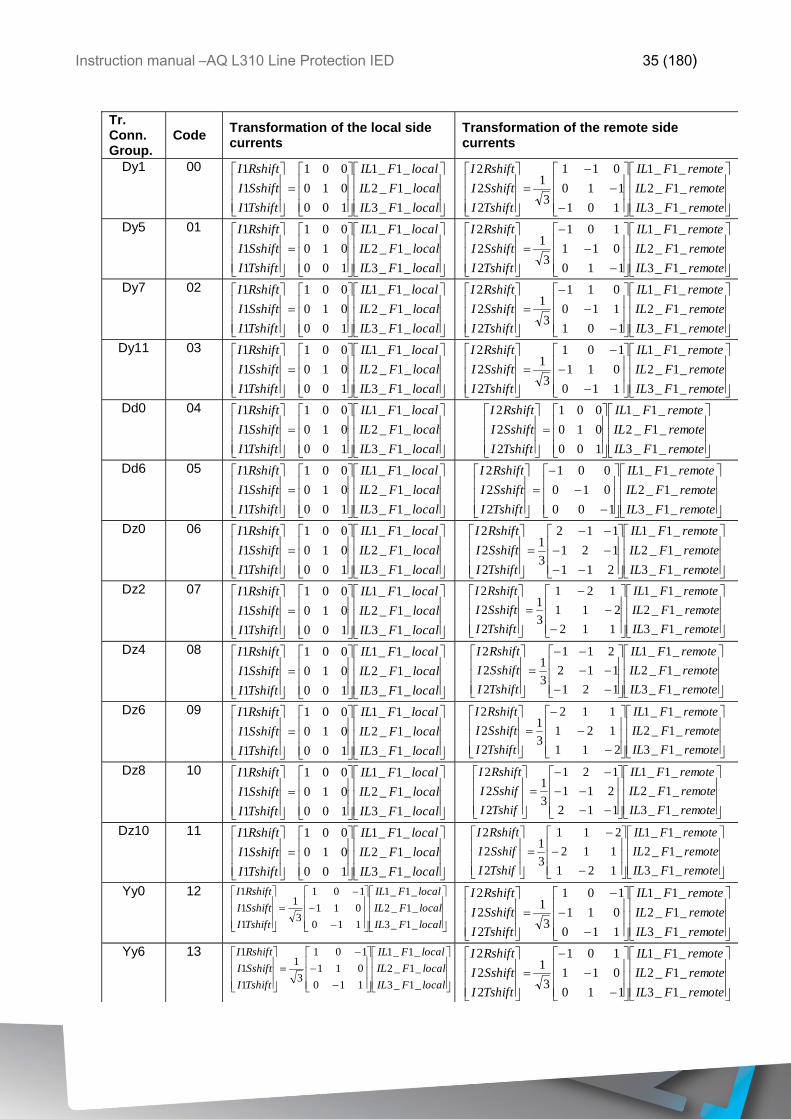
In the vector shift compensation the base Fourier components of the phase currents of the
local side (IL1_F1_local, IL21_F1_local, IL3_F1_local) and those of the remote side
((IL1_F1_remote, IL2_F1_remote, IL3_F1_remote)) are transformed to (I1Rshift, I1Sshift,
I1Tshift) and (I2Rshift, I2Sshift, I2Tshift) values of both sides respectively, using matrix
transformation. The method of transformation is defined by the „Code” parameter,
identifying the transformer vector group connection.
The table below summarizes the method of transformation, according to the connection
group of the transformers with two voltage levels.
Instruction manual –AQ L310 Line Protection IED 35 (180)
Tr. Conn. Group.
Code Transformation of the local side currents
Transformation of the remote side currents
Dy1 00
localFIL
localFIL
localFIL
TshiftI
SshiftI
RshiftI
_1_3
_1_2
_1_1
100
010
001
1
1
1
remoteFIL
remoteFIL
remoteFIL
TshiftI
SshiftI
RshiftI
_1_3
_1_2
_1_1
101
110
011
3
1
2
2
2
Dy5 01
localFIL
localFIL
localFIL
TshiftI
SshiftI
RshiftI
_1_3
_1_2
_1_1
100
010
001
1
1
1
remoteFIL
remoteFIL
remoteFIL
TshiftI
SshiftI
RshiftI
_1_3
_1_2
_1_1
110
011
101
3
1
2
2
2
Dy7 02
localFIL
localFIL
localFIL
TshiftI
SshiftI
RshiftI
_1_3
_1_2
_1_1
100
010
001
1
1
1
remoteFIL
remoteFIL
remoteFIL
TshiftI
SshiftI
RshiftI
_1_3
_1_2
_1_1
101
110
011
3
1
2
2
2
Dy11 03
localFIL
localFIL
localFIL
TshiftI
SshiftI
RshiftI
_1_3
_1_2
_1_1
100
010
001
1
1
1
remoteFIL
remoteFIL
remoteFIL
TshiftI
SshiftI
RshiftI
_1_3
_1_2
_1_1
110
011
101
3
1
2
2
2
Dd0 04
localFIL
localFIL
localFIL
TshiftI
SshiftI
RshiftI
_1_3
_1_2
_1_1
100
010
001
1
1
1
remoteFIL
remoteFIL
remoteFIL
TshiftI
SshiftI
RshiftI
_1_3
_1_2
_1_1
100
010
001
2
2
2
Dd6 05
localFIL
localFIL
localFIL
TshiftI
SshiftI
RshiftI
_1_3
_1_2
_1_1
100
010
001
1
1
1
remoteFIL
remoteFIL
remoteFIL
TshiftI
SshiftI
RshiftI
_1_3
_1_2
_1_1
100
010
001
2
2
2
Dz0 06
localFIL
localFIL
localFIL
TshiftI
SshiftI
RshiftI
_1_3
_1_2
_1_1
100
010
001
1
1
1
remoteFIL
remoteFIL
remoteFIL
TshiftI
SshiftI
RshiftI
_1_3
_1_2
_1_1
211
121
112
3
1
2
2
2
Dz2 07
localFIL
localFIL
localFIL
TshiftI
SshiftI
RshiftI
_1_3
_1_2
_1_1
100
010
001
1
1
1
remoteFIL
remoteFIL
remoteFIL
TshiftI
SshiftI
RshiftI
_1_3
_1_2
_1_1
112
211
121
3
1
2
2
2
Dz4 08
localFIL
localFIL
localFIL
TshiftI
SshiftI
RshiftI
_1_3
_1_2
_1_1
100
010
001
1
1
1
remoteFIL
remoteFIL
remoteFIL
TshiftI
SshiftI
RshiftI
_1_3
_1_2
_1_1
121
112
211
3
1
2
2
2
Dz6 09
localFIL
localFIL
localFIL
TshiftI
SshiftI
RshiftI
_1_3
_1_2
_1_1
100
010
001
1
1
1
remoteFIL
remoteFIL
remoteFIL
TshiftI
SshiftI
RshiftI
_1_3
_1_2
_1_1
211
121
112
3
1
2
2
2
Dz8 10
localFIL
localFIL
localFIL
TshiftI
SshiftI
RshiftI
_1_3
_1_2
_1_1
100
010
001
1
1
1
remoteFIL
remoteFIL
remoteFIL
TshifI
SshifI
RshiftI
_1_3
_1_2
_1_1
112
211
121
3
1
2
2
2
Dz10 11
localFIL
localFIL
localFIL
TshiftI
SshiftI
RshiftI
_1_3
_1_2
_1_1
100
010
001
1
1
1
remoteFIL
remoteFIL
remoteFIL
TshifI
SshifI
RshiftI
_1_3
_1_2
_1_1
121
112
211
3
1
2
2
2
Yy0 12
localFIL
localFIL
localFIL
TshiftI
SshiftI
RshiftI
_1_3
_1_2
_1_1
110
011
101
3
1
1
1
1
remoteFIL
remoteFIL
remoteFIL
TshiftI
SshiftI
RshiftI
_1_3
_1_2
_1_1
110
011
101
3
1
2
2
2
Yy6 13
localFIL
localFIL
localFIL
TshiftI
SshiftI
RshiftI
_1_3
_1_2
_1_1
110
011
101
3
1
1
1
1
remoteFIL
remoteFIL
remoteFIL
TshiftI
SshiftI
RshiftI
_1_3
_1_2
_1_1
110
011
101
3
1
2
2
2
Instruction manual –AQ L310 Line Protection IED 36 (180)
Yd1 14
localFIL
localFIL
localFIL
TshiftI
SshiftI
RshiftI
_1_3
_1_2
_1_1
110
011
101
3
1
1
1
1
remoteFIL
remoteFIL
remoteFIL
TshiftI
SshiftI
RshiftI
_1_3
_1_2
_1_1
100
010
001
2
2
2
Yd5 15
localFIL
localFIL
localFIL
TshiftI
SshiftI
RshiftI
_1_3
_1_2
_1_1
101
110
011
3
1
1
1
1
remoteFIL
remoteFIL
remoteFIL
TshiftI
SshiftI
RshiftI
_1_3
_1_2
_1_1
100
010
001
2
2
2
Yd7 16
localFIL
localFIL
localFIL
TshiftI
SshiftI
RshiftI
_1_3
_1_2
_1_1
110
011
101
3
1
1
1
1
remoteFIL
remoteFIL
remoteFIL
TshiftI
SshiftI
RshiftI
_1_3
_1_2
_1_1
100
010
001
2
2
2
Yd11 17
localFIL
localFIL
localFIL
TshiftI
SshiftI
RshiftI
_1_3
_1_2
_1_1
101
110
011
3
1
1
1
1
remoteFIL
remoteFIL
remoteFIL
TshiftI
SshiftI
RshiftI
_1_3
_1_2
_1_1
100
010
001
2
2
2
Yz1 18
localFIL
localFIL
localFIL
TshiftI
SshiftI
RshiftI
_1_3
_1_2
_1_1
110
011
101
3
1
1
1
1
remoteFIL
remoteFIL
remoteFIL
TshiftI
SshiftI
RshiftI
_1_3
_1_2
_1_1
211
121
112
3
1
2
2
2
Yz5 19
localFIL
localFIL
localFIL
TshiftI
SshiftI
RshiftI
_1_3
_1_2
_1_1
101
110
011
3
1
1
1
1
remoteFIL
remoteFIL
remoteFIL
TshiftI
SshiftI
RshiftI
_1_1
_1_1
_1_1
211
121
112
3
1
2
2
2
Yz7 20
localFIL
localFIL
localFIL
TshiftI
SshiftI
RshiftI
_1_3
_1_2
_1_1
110
011
101
3
1
1
1
1
remoteFIL
remoteFIL
remoteFIL
TshiftI
SshiftI
RshiftI
_1_3
_1_2
_1_1
211
121
112
3
1
2
2
2
Yz11 21
localFIL
localFIL
localFIL
TshiftI
SshiftI
RshiftI
_1_3
_1_2
_1_1
101
110
011
3
1
1
1
1
remoteFIL
remoteFIL
remoteFIL
TshiftI
SshiftI
RshiftI
_1_3
_1_2
_1_1
211
121
112
3
1
2
2
2
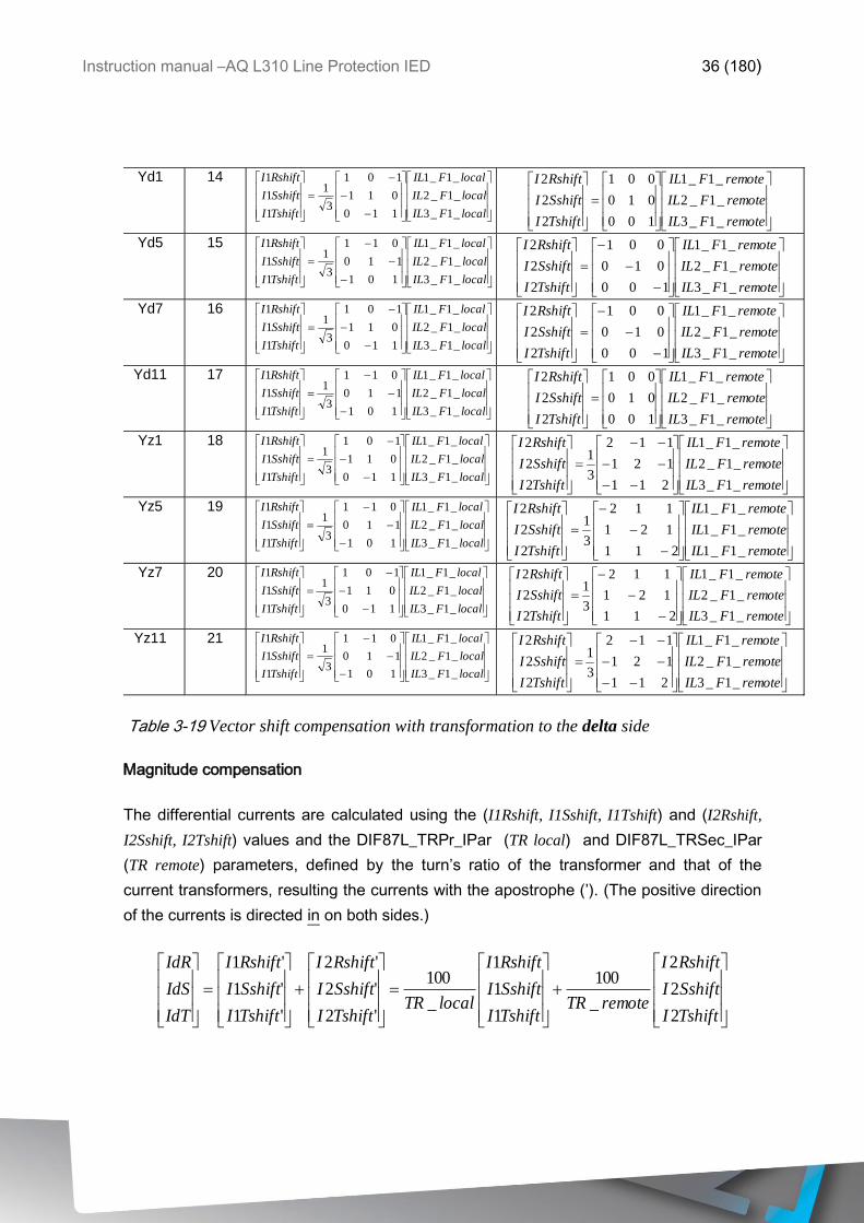
Table 3-19 Vector shift compensation with transformation to the delta side
Magnitude compensation
The differential currents are calculated using the (I1Rshift, I1Sshift, I1Tshift) and (I2Rshift,
I2Sshift, I2Tshift) values and the DIF87L_TRPr_IPar (TR local) and DIF87L_TRSec_IPar
(TR remote) parameters, defined by the turn’s ratio of the transformer and that of the
current transformers, resulting the currents with the apostrophe (’). (The positive direction
of the currents is directed in on both sides.)
TshiftI
SshiftI
RshiftI
remoteTRTshiftI
SshiftI
RshiftI
localTRTshiftI
SshiftI
RshiftI
TshiftI
SshiftI
RshiftI
IdT
IdS
IdR
2
2
2
_
100
1
1
1
_
100
'2
'2
'2
'1
'1
'1
Instruction manual –AQ L310 Line Protection IED 37 (180)
The current measuring software modules process these Fourier base harmonic values of
the differential currents.
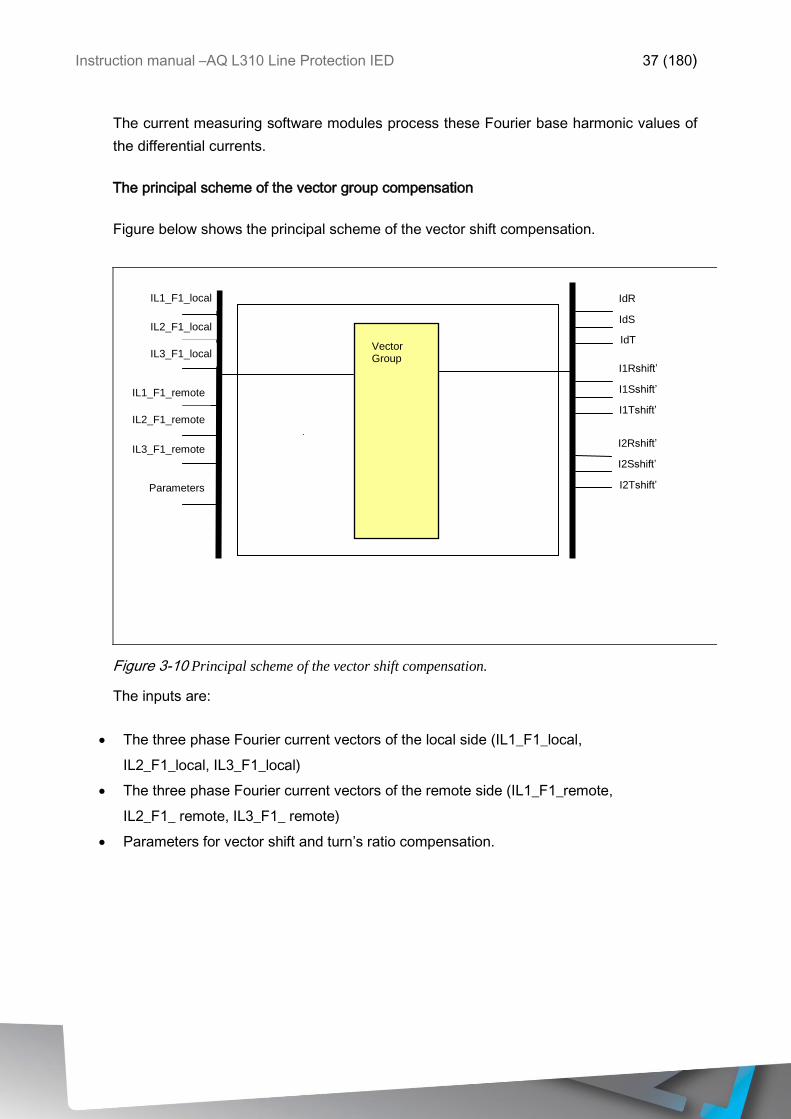
The principal scheme of the vector group compensation
Figure below shows the principal scheme of the vector shift compensation.
IL1_F1_local
Vector Group
Parameters
IdR
IdS
IdT
I1Rshift’
I1Sshift’
I1Tshift’
I2Rshift’
I2Sshift’
I2Tshift’
IL2_F1_local
IL3_F1_local
IL1_F1_remote
IL2_F1_remote
IL3_F1_remote
Figure 3-10 Principal scheme of the vector shift compensation.
The inputs are:
The three phase Fourier current vectors of the local side (IL1_F1_local,
IL2_F1_local, IL3_F1_local)
The three phase Fourier current vectors of the remote side (IL1_F1_remote,
IL2_F1_ remote, IL3_F1_ remote)
Parameters for vector shift and turn’s ratio compensation.
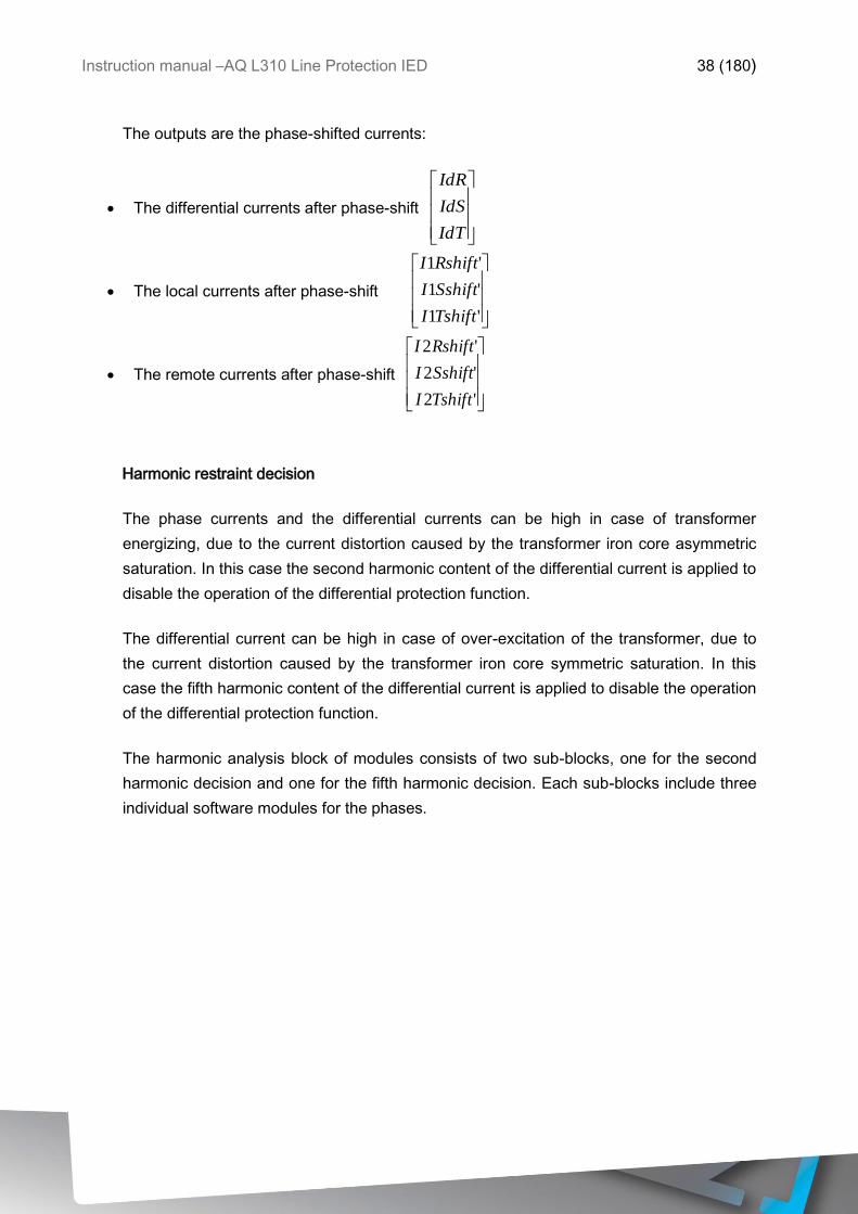
Instruction manual –AQ L310 Line Protection IED 38 (180)
The outputs are the phase-shifted currents:
The differential currents after phase-shift
IdT
IdS
IdR
The local currents after phase-shift
'1
'1
'1
TshiftI
SshiftI
RshiftI
The remote currents after phase-shift
'2
'2
'2
TshiftI
SshiftI
RshiftI
Harmonic restraint decision
The phase currents and the differential currents can be high in case of transformer
energizing, due to the current distortion caused by the transformer iron core asymmetric
saturation. In this case the second harmonic content of the differential current is applied to
disable the operation of the differential protection function.
The differential current can be high in case of over-excitation of the transformer, due to
the current distortion caused by the transformer iron core symmetric saturation. In this
case the fifth harmonic content of the differential current is applied to disable the operation
of the differential protection function.
The harmonic analysis block of modules consists of two sub-blocks, one for the second
harmonic decision and one for the fifth harmonic decision. Each sub-blocks include three
individual software modules for the phases.
Instruction manual –AQ L310 Line Protection IED 39 (180)
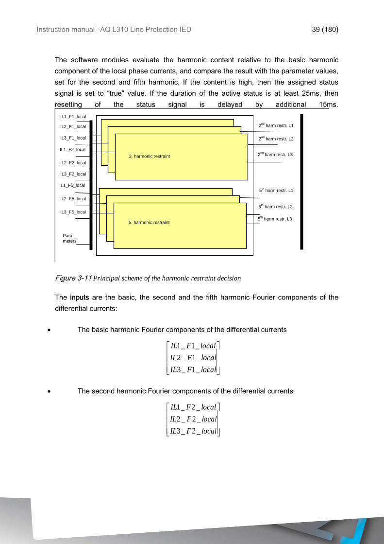
The software modules evaluate the harmonic content relative to the basic harmonic
component of the local phase currents, and compare the result with the parameter values,
set for the second and fifth harmonic. If the content is high, then the assigned status
signal is set to “true” value. If the duration of the active status is at least 25ms, then
resetting of the status signal is delayed by additional 15ms.
IL1_F1_local
2nd
harm restr. L1
2nd
harm restr. L2
2nd
harm restr. L3
5th harm restr. L1
5th harm restr. L2
5th harm restr. L3
Para meters
2. harmonic restraint
5. harmonic restraint
IL2_F1_local
IL3_F1_local
IL3_F2_local
IL2_F2_local
IL2_F5_local
IL3_F5_local
IL1_F2_local
IL1_F5_local
Figure 3-11 Principal scheme of the harmonic restraint decision
The inputs are the basic, the second and the fifth harmonic Fourier components of the
differential currents:
The basic harmonic Fourier components of the differential currents
localFIL
localFIL
localFIL
_1_3
_1_2
_1_1
The second harmonic Fourier components of the differential currents
localFIL
localFIL
localFIL
_2_3
_2_2
_2_1
Instruction manual –AQ L310 Line Protection IED 40 (180)
The fifth harmonic Fourier components of the differential currents
localFIL
localFIL
localFIL
_5_3
_5_2
_5_1
Parameters
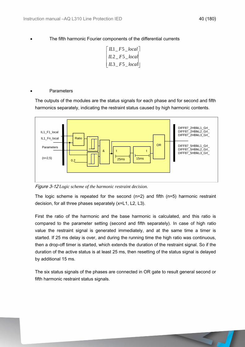
The outputs of the modules are the status signals for each phase and for second and fifth
harmonics separately, indicating the restraint status caused by high harmonic contents.
IL1_F1_local
DIFF87_2HBlkL1_GrI_ DIFF87_2HBlkL2_GrI_ DIFF87_2HBlkL3_GrI_ DIFF87_5HBlkL1_GrI_ DIFF87_5HBlkL2_GrI_ DIFF87_5HBlkL3_GrI_
Parameters (n=2,5)
Ratio
25ms
t t
15ms
OR
0.2
&
IL1_Fn_local
Figure 3-12 Logic scheme of the harmonic restraint decision.
The logic scheme is repeated for the second (n=2) and fifth (n=5) harmonic restraint
decision, for all three phases separately (x=L1, L2, L3).
First the ratio of the harmonic and the base harmonic is calculated, and this ratio is
compared to the parameter setting (second and fifth separately). In case of high ratio
value the restraint signal is generated immediately, and at the same time a timer is
started. If 25 ms delay is over, and during the running time the high ratio was continuous,
then a drop-off timer is started, which extends the duration of the restraint signal. So if the
duration of the active status is at least 25 ms, then resetting of the status signal is delayed
by additional 15 ms.
The six status signals of the phases are connected in OR gate to result general second or
fifth harmonic restraint status signals.
Instruction manual –AQ L310 Line Protection IED 41 (180)
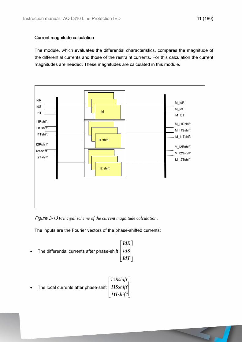
Current magnitude calculation
The module, which evaluates the differential characteristics, compares the magnitude of
the differential currents and those of the restraint currents. For this calculation the current
magnitudes are needed. These magnitudes are calculated in this module.
IdR
IdS
IdT
I1Rshift’
I1Sshift’
I1Tshift’
I2Rshift’
I2Sshift’
I2Tshift’
Id
I1 shift’
I2 shift’
M_IdR
M_IdS
M_IdT
M_I1Rshift’
M_I1Sshift’
M_I1Tshift’
M_I2Rshift’
M_I2Sshift’
M_I2Tshift’
Figure 3-13 Principal scheme of the current magnitude calculation.
The inputs are the Fourier vectors of the phase-shifted currents:
The differential currents after phase-shift
IdT
IdS
IdR
The local currents after phase-shift
'1
'1
'1
TshiftI
SshiftI
RshiftI
Instruction manual –AQ L310 Line Protection IED 42 (180)
The remote currents after phase-shift
'2
'2
'2
TshiftI
SshiftI
RshiftI
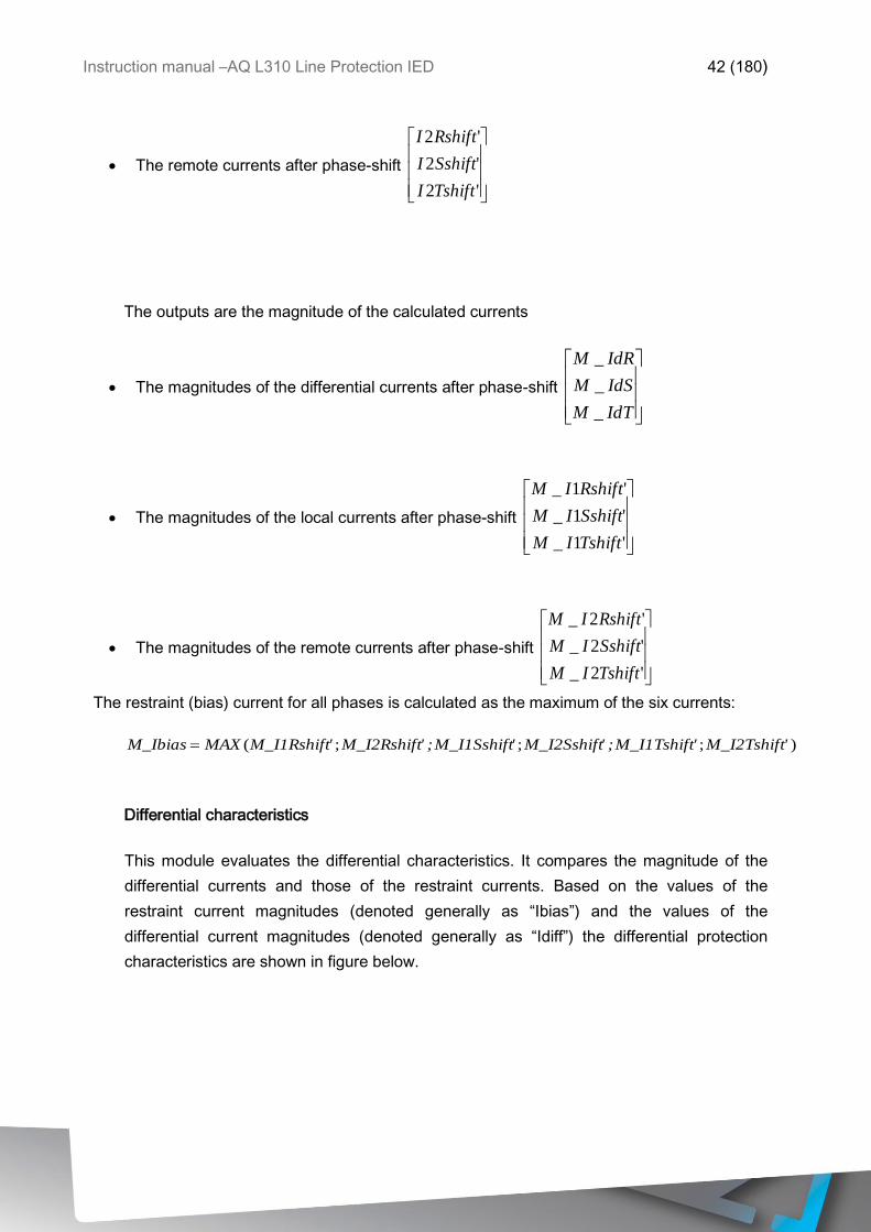
The outputs are the magnitude of the calculated currents
The magnitudes of the differential currents after phase-shift
IdTM
IdSM
IdRM
_
_
_
The magnitudes of the local currents after phase-shift
'1_
'1_
'1_
TshiftIM
SshiftIM
RshiftIM
The magnitudes of the remote currents after phase-shift
'2_
'2_
'2_
TshiftIM
SshiftIM
RshiftIM
The restraint (bias) current for all phases is calculated as the maximum of the six currents:
);;;( 'M_I2Tshift'M_I1Tshift;'M_I2Sshift'M_I1Sshift;'M_I2Rshift'M_I1RshiftMAXM_Ibias
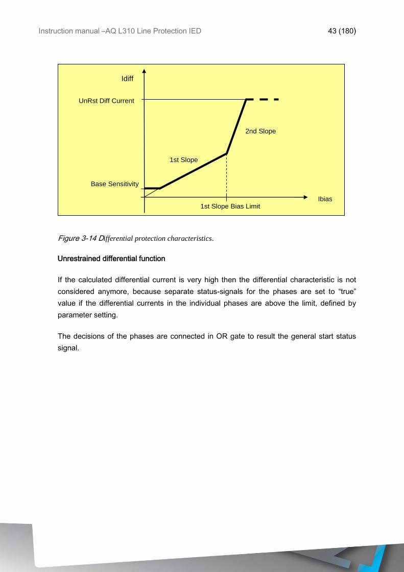
Differential characteristics
This module evaluates the differential characteristics. It compares the magnitude of the
differential currents and those of the restraint currents. Based on the values of the
restraint current magnitudes (denoted generally as “Ibias”) and the values of the
differential current magnitudes (denoted generally as “Idiff”) the differential protection
characteristics are shown in figure below.
Instruction manual –AQ L310 Line Protection IED 43 (180)
Ibias
1st Slope
1st Slope Bias Limit
Base Sensitivity
2nd Slope
Idiff
UnRst Diff Current
Figure 3-14 Differential protection characteristics.
Unrestrained differential function
If the calculated differential current is very high then the differential characteristic is not
considered anymore, because separate status-signals for the phases are set to “true”
value if the differential currents in the individual phases are above the limit, defined by
parameter setting.
The decisions of the phases are connected in OR gate to result the general start status
signal.
Instruction manual –AQ L310 Line Protection IED 44 (180)
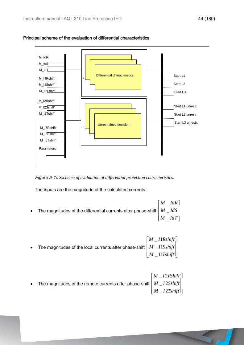
Principal scheme of the evaluation of differential characteristics
M_IdR
M_IdS
M_IdT
M_I1Rshift’
M_I1Sshift’
M_I1Tshift’
M_I2Rshift’
M_I2Sshift’
M_I2Tshift’
M_I3Rshift’
M_I3Sshift’ M_I3Tshift’
Start L1
Start L2
Start L3
Start L1 unrestr.
Start L2 unrestr.
Start L3 unrestr.
Differential characteristics
Unrestrained decision
Parameters
Figure 3-15 Sscheme of evaluation of differential protection characteristics.
The inputs are the magnitude of the calculated currents:
The magnitudes of the differential currents after phase-shift
IdTM
IdSM
IdRM
_
_
_
The magnitudes of the local currents after phase-shift
'1_
'1_
'1_
TshiftIM
SshiftIM
RshiftIM
The magnitudes of the remote currents after phase-shift
'2_
'2_
'2_
TshiftIM
SshiftIM
RshiftIM
Instruction manual –AQ L310 Line Protection IED 45 (180)
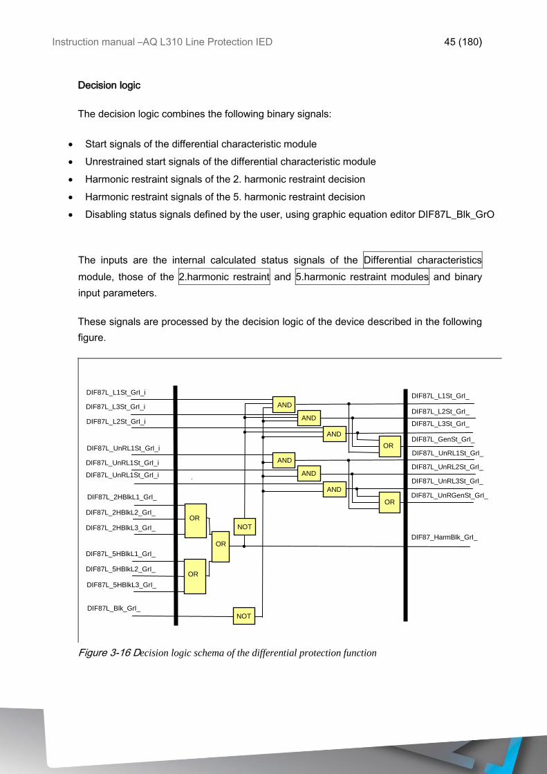
Decision logic
The decision logic combines the following binary signals:
Start signals of the differential characteristic module
Unrestrained start signals of the differential characteristic module
Harmonic restraint signals of the 2. harmonic restraint decision
Harmonic restraint signals of the 5. harmonic restraint decision
Disabling status signals defined by the user, using graphic equation editor DIF87L_Blk_GrO
The inputs are the internal calculated status signals of the Differential characteristics
module, those of the 2.harmonic restraint and 5.harmonic restraint modules and binary
input parameters.
These signals are processed by the decision logic of the device described in the following
figure.
DIF87L_L1St_GrI_i
DIF87L_L2St_GrI_i
DIF87L_L3St_GrI_i
DIF87L_UnRL1St_GrI_i
DIF87L_UnRL1St_GrI_i
DIF87L_UnRL1St_GrI_i
DIF87L_2HBlkL1_GrI_
DIF87L_2HBlkL2_GrI_
DIF87L_2HBlkL3_GrI_
DIF87L_5HBlkL1_GrI_
DIF87L_5HBlkL2_GrI_
DIF87L_5HBlkL3_GrI_
DIF87L_Blk_GrI_
OR
OR
DIF87L_L1St_GrI_
OR
AND
AND
AND
AND
AND
AND
OR
OR
DIF87L_L2St_GrI_
DIF87L_L3St_GrI_
DIF87L_GenSt_GrI_
DIF87L_UnRL1St_GrI_
DIF87L_UnRL2St_GrI_
DIF87L_UnRL3St_GrI_
DIF87L_UnRGenSt_GrI_
DIF87_HarmBlk_GrI_
NOT
NOT
Figure 3-16 Decision logic schema of the differential protection function
Instruction manual –AQ L310 Line Protection IED 46 (180)
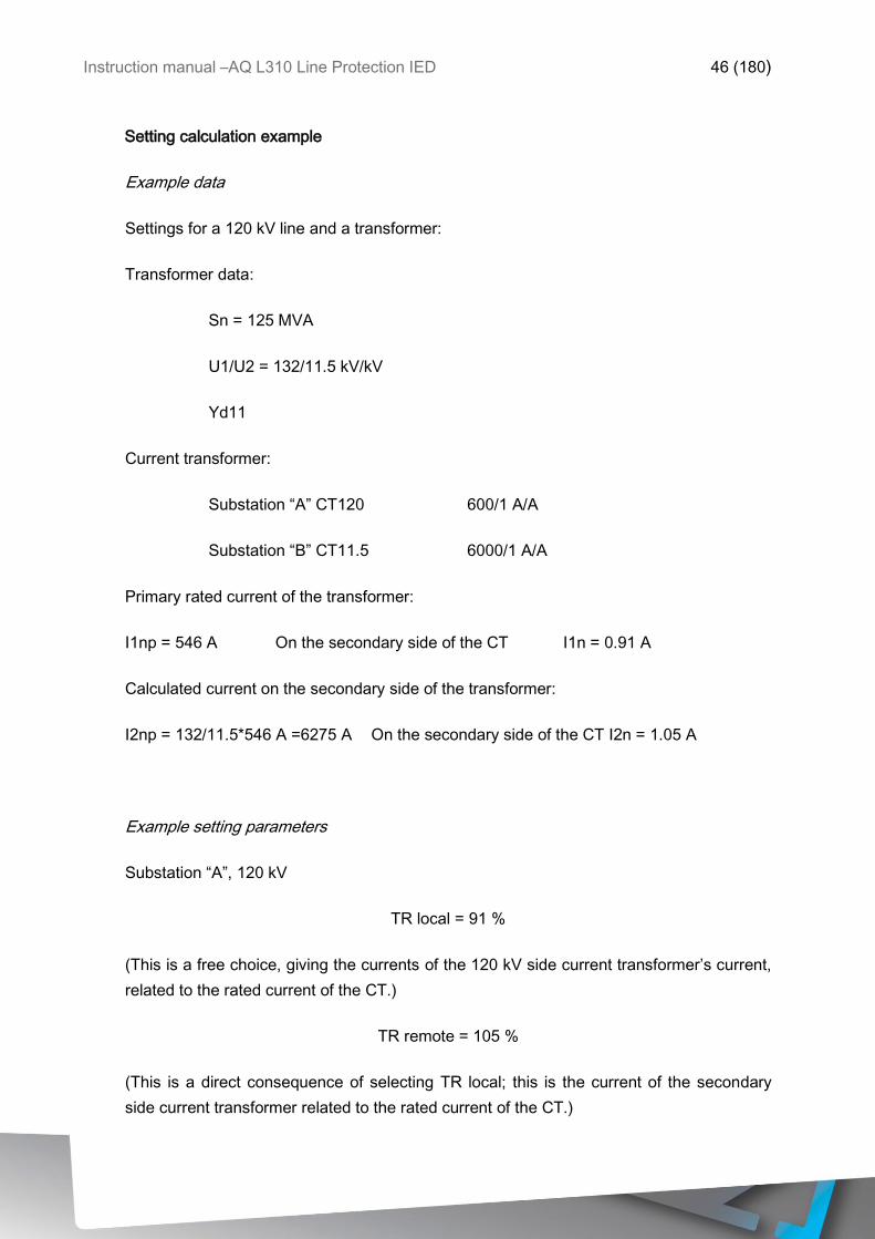
Setting calculation example
Example data
Settings for a 120 kV line and a transformer:
Transformer data:
Sn = 125 MVA
U1/U2 = 132/11.5 kV/kV
Yd11
Current transformer:
Substation “A” CT120 600/1 A/A
Substation “B” CT11.5 6000/1 A/A
Primary rated current of the transformer:
I1np = 546 A On the secondary side of the CT I1n = 0.91 A
Calculated current on the secondary side of the transformer:
I2np = 132/11.5*546 A =6275 A On the secondary side of the CT I2n = 1.05 A
Example setting parameters
Substation “A”, 120 kV
TR local = 91 %
(This is a free choice, giving the currents of the 120 kV side current transformer’s current,
related to the rated current of the CT.)
TR remote = 105 %
(This is a direct consequence of selecting TR local; this is the current of the secondary
side current transformer related to the rated current of the CT.)
Instruction manual –AQ L310 Line Protection IED 47 (180)
The code value of the transformer’s connection group (see Table 1-1) (Yd11):
VGroup = Yd11
Substation “B”, 11.5 kV
TR local = 105 %
(Opposite to substation “A”.)
TR remote = 91 %
(Opposite to substation “A”.)
The code value of the transformer’s connection group seen from the location of the
current transformer (reference is the d side)
VGroup = Dy1
(Mirrored as compared to substation “A”.)
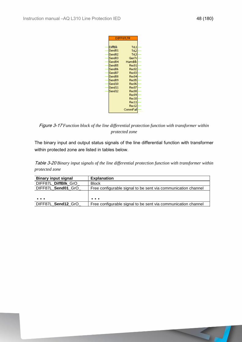
The symbol of the function block in the AQtivate 300 software
The function block of the line differential function with transformer within protected zone is
shown in figure bellow. This block shows all binary input and output status signals that are
applicable in the AQtivate 300 software.
Instruction manual –AQ L310 Line Protection IED 48 (180)
Figure 3-17 Function block of the line differential protection function with transformer within
protected zone
The binary input and output status signals of the line differential function with transformer
within protected zone are listed in tables below.
Table 3-20 Binary input signals of the line differential protection function with transformer within
protected zone
Binary input signal Explanation
DIFF87L_DiffBlk_GrO_ Block
DIFF87L_Send01_GrO_ Free configurable signal to be sent via communication channel
… …
DIFF87L_Send12_GrO_ Free configurable signal to be sent via communication channel
Instruction manual –AQ L310 Line Protection IED 49 (180)
Table 3-21 Binary output signals of the line differential protection function with transformer
within protected zone
Binary output signals Signal title Explanation
Trip commands of the line differential protection function
DIFF87L_TrL1_GrI_ Trip L1 Trip command in line L1
DIFF87L_TrL2_GrI_ Trip L2 Trip command in line L2
DIFF87L_TrL3_GrI_ Trip L3 Trip command in line L3
DIFF87L_GenTr_GrI_ Trip General trip command
Harmonic blocking
DIFF87L_HarmBlk_GrI_ Harmonic restr. Harmonic blocking
Free configurable signals to be sent via communication channel
DIFF87L_Rec01_GrI_ Received Ch01 Free configurable signal received via communication channel
… … …
DIFF87L_Rec12_GrI_ Received Ch12 Free configurable signal received via communication channel
Communication failure signal
DIFF87L_CommFail_GrI_ CommFail Signal indicating communication failure
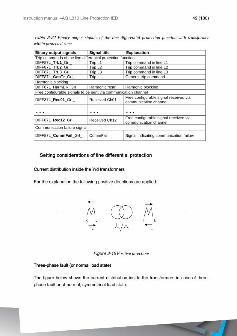
Setting considerations of line differential protection
Current distribution inside the Y/d transformers
For the explanation the following positive directions are applied:
K L l k
+ +
Figure 3-18 Positive directions
Three-phase fault (or normal load state)
The figure below shows the current distribution inside the transformers in case of three-
phase fault or at normal, symmetrical load state:
Instruction manual –AQ L310 Line Protection IED 50 (180)
r
TR
t
S
s
a2*I1Rinput*k/√3
I1Rinput I2Rinput
I1Rinput*k/√3
a*I1Rinput
I2Tinput
a2*I1Rinput
I2Sinput
a*I1Rinput*k/√3
R
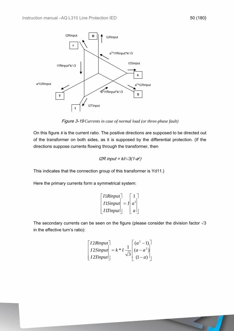
Figure 3-19 Currents in case of normal load (or three-phase fault)
On this figure k is the current ratio. The positive directions are supposed to be directed out
of the transformer on both sides, as it is supposed by the differential protection. (If the
directions suppose currents flowing through the transformer, then
I2R input = kI/√3(1-a2)
This indicates that the connection group of this transformer is Yd11.)
Here the primary currents form a symmetrical system:
a
aI
TinputI
SinputI
RinputI2
1
1
1
1
The secondary currents can be seen on the figure (please consider the division factor √3
in the effective turn’s ratio):
)1(
)(
)1(
3
1*
2
2
22
2
a
aa
a
Ik
TinputI
SinputI
RinputI
Instruction manual –AQ L310 Line Protection IED 51 (180)
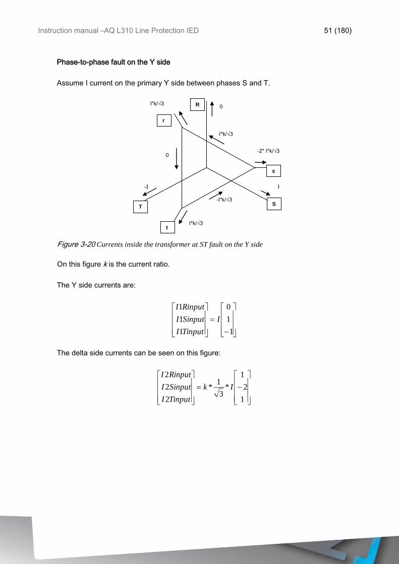
Phase-to-phase fault on the Y side
Assume I current on the primary Y side between phases S and T.
r
TR
t
S
s
I*k/√3
0 I*k/√3
0
-I
I*k/√3
-2* I*k/√3
-I*k/√3
R
I
Figure 3-20 Currents inside the transformer at ST fault on the Y side
On this figure k is the current ratio.
The Y side currents are:
1
1
0
1
1
1
I
TinputI
SinputI
RinputI
The delta side currents can be seen on this figure:
1
2
1
*3
1*
2
2
2
Ik
TinputI
SinputI
RinputI
I
Instruction manual –AQ L310 Line Protection IED 52 (180)
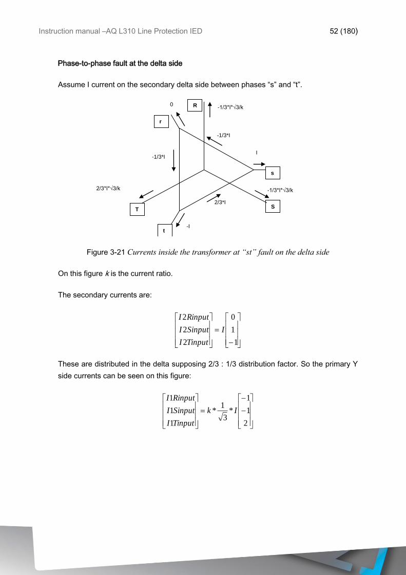
Phase-to-phase fault at the delta side
Assume I current on the secondary delta side between phases “s” and “t”.
r
TR
t
S
s
-1/3*I
-1/3*I*√3/k 0
-1/3*I
2/3*I*√3/k
-I
-1/3*I*√3/k
I
2/3*I
R
Figure 3-21 Currents inside the transformer at “st” fault on the delta side
On this figure k is the current ratio.
The secondary currents are:
1
1
0
2
2
2
I
TinputI
SinputI
RinputI
These are distributed in the delta supposing 2/3 : 1/3 distribution factor. So the primary Y
side currents can be seen on this figure:
2
1
1
*3
1*
1
1
1
Ik
TinputI
SinputI
RinputI
Instruction manual –AQ L310 Line Protection IED 53 (180)
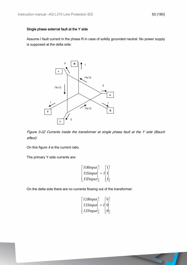
Single phase external fault at the Y side
Assume I fault current in the phase R in case of solidly grounded neutral. No power supply
is supposed at the delta side:
r
TR
t
S
s
I*k/√3
I 0
I*k/√3
I
0
I
0
I*k/√3
R
Figure 3-22 Currents inside the transformer at single phase fault at the Y side (Bauch
effect)
On this figure k is the current ratio.
The primary Y side currents are:
1
1
1
1
1
1
I
TinputI
SinputI
RinputI
On the delta side there are no currents flowing out of the transformer:
0
0
0
2
2
2
I
TinputI
SinputI
RinputI
Instruction manual –AQ L310 Line Protection IED 54 (180)
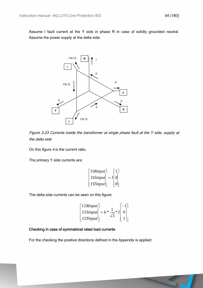
Assume I fault current at the Y side in phase R in case of solidly grounded neutral.
Assume the power supply at the delta side:
r
TR
t
S
s
0
I - I*k/√3
I*k/√3
0
I*k/√3
0
0
0
R
Figure 3-23 Currents inside the transformer at single phase fault at the Y side, supply at
the delta side
On this figure k is the current ratio.
The primary Y side currents are:
0
0
1
1
1
1
I
TinputI
SinputI
RinputI
The delta side currents can be seen on this figure:
1
0
1
*3
1*
2
2
2
Ik
TinputI
SinputI
RinputI
Checking in case of symmetrical rated load currents
For the checking the positive directions defined in the Appendix is applied:

Instruction manual –AQ L310 Line Protection IED 55 (180)
Based on Figure 3-19 , the primary currents are:
The transformed values of the primary side:
)1(
)(
)1(
00183.0*13
1
`1
`1
`1
)1(
)(
)1(
_
100*
600
1*1
3
1
1
1
1
101
110
011
3
1
_
100
`1
`1
`1
2
2
2
2
a
aa
a
npI
TshiftI
SshiftI
RshiftI
a
aa
a
localTRnpI
TinputI
SinputI
RinputI
localTRTshiftI
SshiftI
RshiftI
The secondary currents are drawn in Figure 3-19 (consider the division by √3 as defined
by the turn’s ratio):
The secondary currents are transformed by the unit matrix. It means that only the turn’s
ratio is considered:
)1(
)(
)1(
00182.0*13
1
`2
`2
`2
)1(
)(
)1(
*6000
1*
3
1*
5.11
132*1*
_
100
`2
`2
`2
2
2
2
2
a
aa
a
npI
TshiftI
SshiftI
RshiftI
a
aa
a
npIremoteTR
TshiftI
SshiftI
RshiftI
These currents are the same (with the round-off errors of. 0.5%) as the primary
transformed currents, but multiplied by „-1”. As the differential currents are the sum of the
shifted phase currents, these all result zero, the differential protection id balanced.
a
anpI
TinputI
SinputI
RinputI2
1
600
1*1
1
1
1
)1(
)(
)1(
6000
1*
3
1*
5.11
132*1
2
2
22
2
a
aa
a
npI
RinputI
RinputI
RinputI
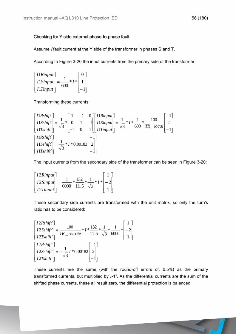
Instruction manual –AQ L310 Line Protection IED 56 (180)
Checking for Y side external phase-to-phase fault
Assume I fault current at the Y side of the transformer in phases S and T.
According to Figure 3-20 the input currents from the primary side of the transformer:
Transforming these currents:
1
2
1
00183.0**3
1
`1
`1
`1
1
2
1
_
100*
600
1**
3
1
1
1
1
101
110
011
*3
1
`1
`1
`1
I
TshiftI
SshiftI
RshiftI
localTRI
TinputI
SinputI
RinputI
TshiftI
SshiftI
RshiftI
The input currents from the secondary side of the transformer can be seen in Figure 3-20:
These secondary side currents are transformed with the unit matrix, so only the turn’s
ratio has to be considered:
1
2
1
00182.0*3
1
`2
`2
`2
1
2
1
*6000
1*
3
1*
5.11
132**
_
100
`2
`2
`2
I
TshiftI
SshiftI
RshiftI
IremoteTR
TshiftI
SshiftI
RshiftI
These currents are the same (with the round-off errors of. 0.5%) as the primary
transformed currents, but multiplied by „-1”. As the differential currents are the sum of the
shifted phase currents, these all result zero, the differential protection is balanced.
1
1
0
**600
1
1
1
1
I
TinputI
SinputI
RinputI
1
2
1
**3
1*
5.11
132*
6000
1
2
2
2
I
TinputI
SinputI
RinputI

Instruction manual –AQ L310 Line Protection IED 57 (180)
Here the attention must be drawn to the multiplication factor „2” in phase S. The
consequences must be analyzed in a separate chapter.
Checking for D side external phase-to-phase fault
Assume I fault current at the D side of the transformer in phases S and T.
According to Figure 3-21 the input currents to the differential protection are:
These secondary side currents are transformed with the unit matrix, so only the turn’s
ratio has to be considered:
1
1
0
*10*1587.0
`2
`2
`2
1
1
0
*6000
1*
_
100
`2
`2
`2
3 I
TshiftI
SshiftI
RshiftI
IremoteTR
TshiftI
SshiftI
RshiftI
The input currents form the primary Y side can be seen on Figure 3-21
The transformation of these Y side currents:
1
1
0
*10*1596.0*
`1
`1
`1
1
1
0
132
5.11*
_
100*
600
1**
3
1
1
1
1
101
110
011
*3
1
`1
`1
`1
3I
TshiftI
SshiftI
RshiftI
localTRI
TinputI
SinputI
RinputI
TshiftI
SshiftI
RshiftI
1
1
0
**6000
1
2
2
2
I
TinputI
SinputI
RinputI
2
1
1
3
1**3*
132
5.11*
600
1
1
1
1
I
TinputI
SinputI
RinputI
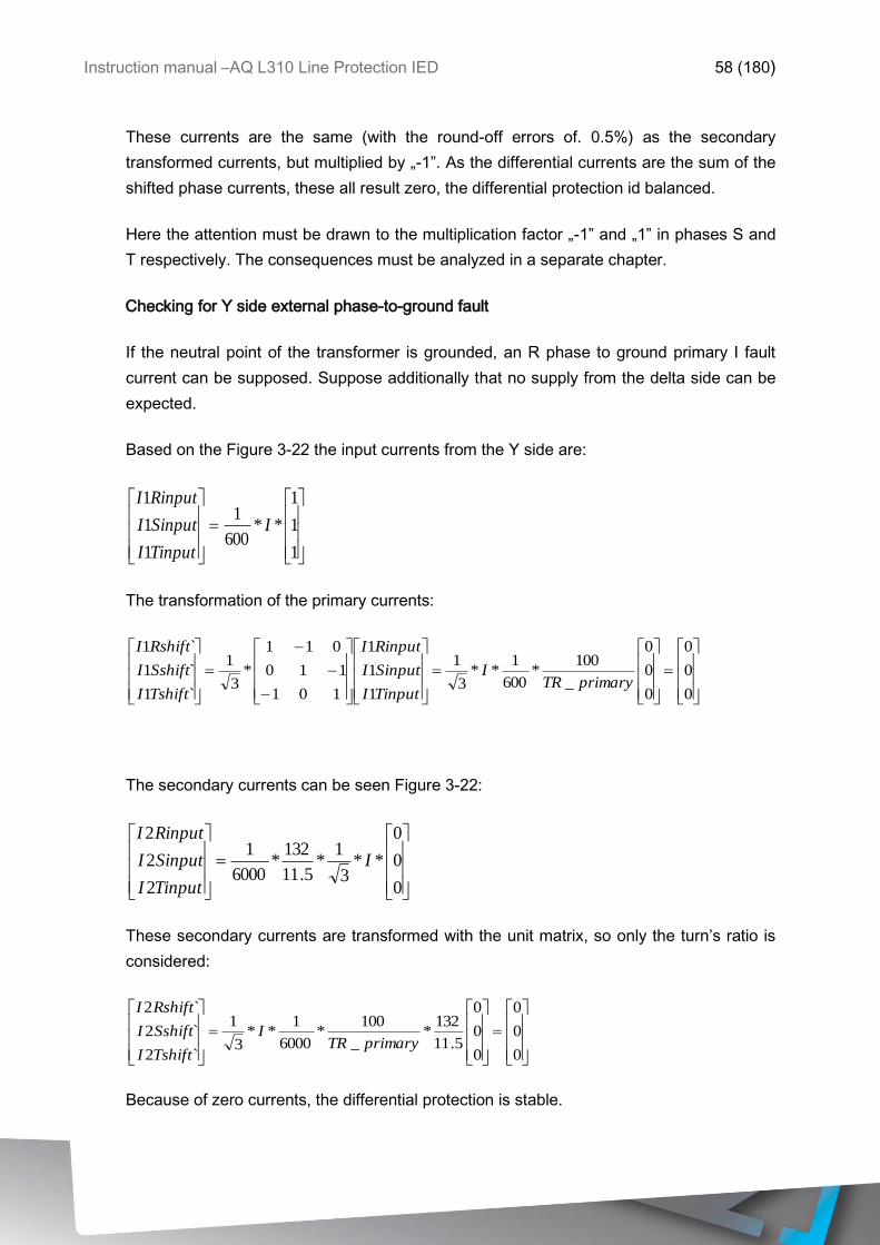
Instruction manual –AQ L310 Line Protection IED 58 (180)
These currents are the same (with the round-off errors of. 0.5%) as the secondary
transformed currents, but multiplied by „-1”. As the differential currents are the sum of the
shifted phase currents, these all result zero, the differential protection id balanced.
Here the attention must be drawn to the multiplication factor „-1” and „1” in phases S and
T respectively. The consequences must be analyzed in a separate chapter.
Checking for Y side external phase-to-ground fault
If the neutral point of the transformer is grounded, an R phase to ground primary I fault
current can be supposed. Suppose additionally that no supply from the delta side can be
expected.
Based on the Figure 3-22 the input currents from the Y side are:
The transformation of the primary currents:
0
0
0
0
0
0
_
100*
600
1**
3
1
1
1
1
101
110
011
*3
1
`1
`1
`1
primaryTRI
TinputI
SinputI
RinputI
TshiftI
SshiftI
RshiftI
The secondary currents can be seen Figure 3-22:
These secondary currents are transformed with the unit matrix, so only the turn’s ratio is
considered:
0
0
0
0
0
0
5.11
132*
_
100*
6000
1**
3
1
`2
`2
`2
primaryTRI
TshiftI
SshiftI
RshiftI
Because of zero currents, the differential protection is stable.
1
1
1
**600
1
1
1
1
I
TinputI
SinputI
RinputI
0
0
0
**3
1*
5.11
132*
6000
1
2
2
2
I
TinputI
SinputI
RinputI
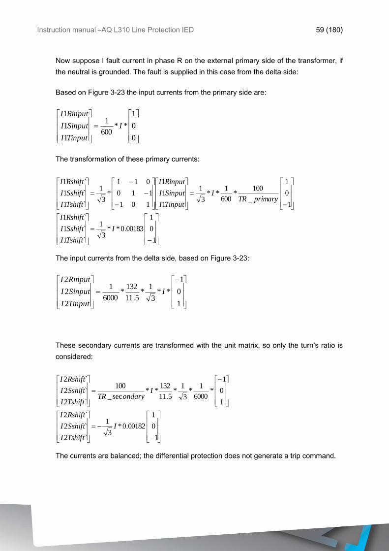
Instruction manual –AQ L310 Line Protection IED 59 (180)
Now suppose I fault current in phase R on the external primary side of the transformer, if
the neutral is grounded. The fault is supplied in this case from the delta side:
Based on Figure 3-23 the input currents from the primary side are:
The transformation of these primary currents:
1
0
1
00183.0**3
1
`1
`1
`1
1
0
1
_
100*
600
1**
3
1
1
1
1
101
110
011
*3
1
`1
`1
`1
I
TshiftI
SshiftI
RshiftI
primaryTRI
TinputI
SinputI
RinputI
TshiftI
SshiftI
RshiftI
The input currents from the delta side, based on Figure 3-23:
These secondary currents are transformed with the unit matrix, so only the turn’s ratio is
considered:
1
0
1
00182.0*3
1
`2
`2
`2
1
0
1
*6000
1*
3
1*
5.11
132**
sec_
100
`2
`2
`2
I
TshiftI
SshiftI
RshiftI
IondaryTR
TshiftI
SshiftI
RshiftI
The currents are balanced; the differential protection does not generate a trip command.
0
0
1
**600
1
1
1
1
I
TinputI
SinputI
RinputI
1
0
1
**3
1*
5.11
132*
6000
1
2
2
2
I
TinputI
SinputI
RinputI
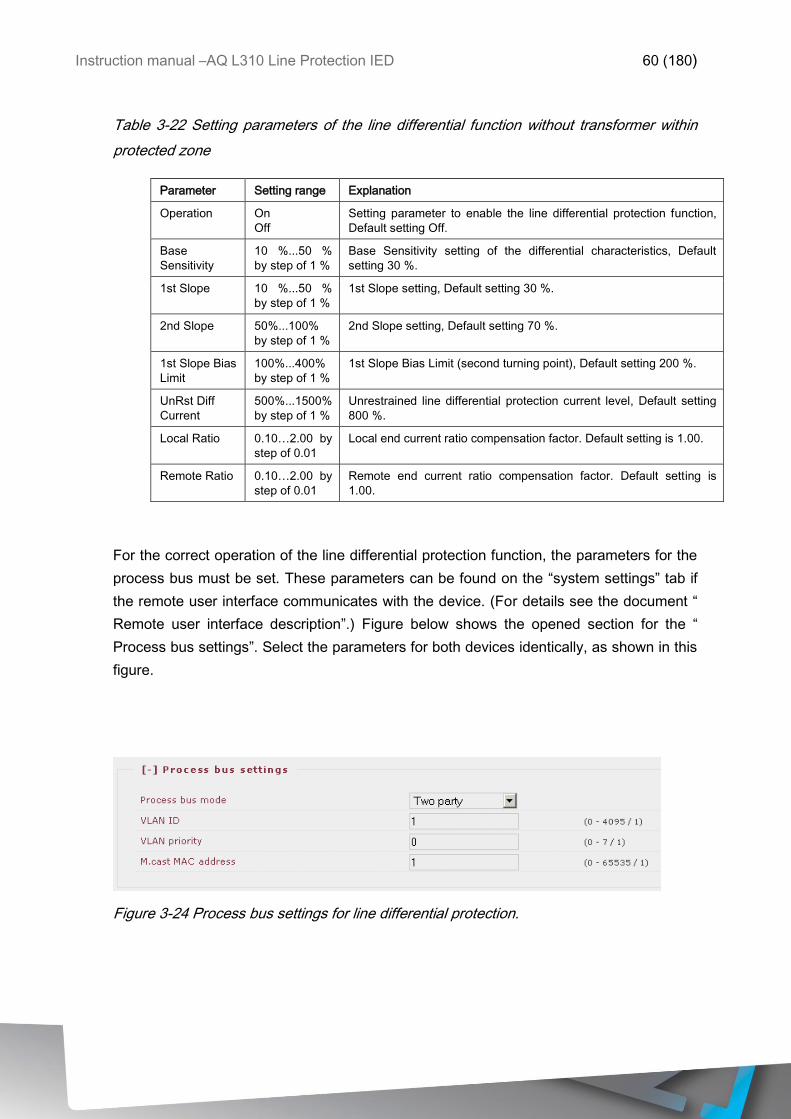
Instruction manual –AQ L310 Line Protection IED 60 (180)
Table 3-22 Setting parameters of the line differential function without transformer within
protected zone
Parameter Setting range Explanation
Operation On
Off
Setting parameter to enable the line differential protection function,
Default setting Off.
Base
Sensitivity
10 %...50 %
by step of 1 %
Base Sensitivity setting of the differential characteristics, Default
setting 30 %.
1st Slope 10 %...50 %
by step of 1 %
1st Slope setting, Default setting 30 %.
2nd Slope 50%...100%
by step of 1 %
2nd Slope setting, Default setting 70 %.
1st Slope Bias
Limit
100%...400%
by step of 1 %
1st Slope Bias Limit (second turning point), Default setting 200 %.
UnRst Diff
Current
500%...1500%
by step of 1 %
Unrestrained line differential protection current level, Default setting
800 %.
Local Ratio 0.10…2.00 by
step of 0.01
Local end current ratio compensation factor. Default setting is 1.00.
Remote Ratio 0.10…2.00 by
step of 0.01
Remote end current ratio compensation factor. Default setting is
1.00.
For the correct operation of the line differential protection function, the parameters for the
process bus must be set. These parameters can be found on the “system settings” tab if
the remote user interface communicates with the device. (For details see the document “
Remote user interface description”.) Figure below shows the opened section for the “
Process bus settings”. Select the parameters for both devices identically, as shown in this
figure.
Figure 3-24 Process bus settings for line differential protection.
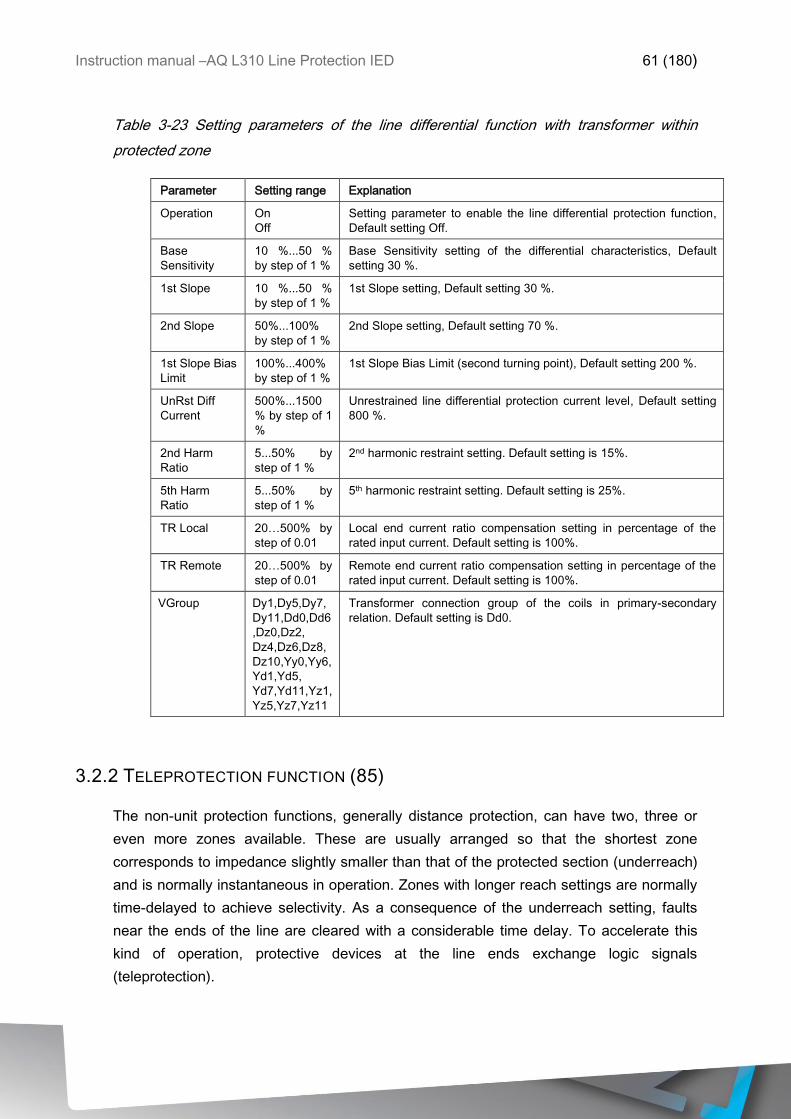
Instruction manual –AQ L310 Line Protection IED 61 (180)
Table 3-23 Setting parameters of the line differential function with transformer within
protected zone
Parameter Setting range Explanation
Operation On
Off
Setting parameter to enable the line differential protection function,
Default setting Off.
Base
Sensitivity
10 %...50 %
by step of 1 %
Base Sensitivity setting of the differential characteristics, Default
setting 30 %.
1st Slope 10 %...50 %
by step of 1 %
1st Slope setting, Default setting 30 %.
2nd Slope 50%...100%
by step of 1 %
2nd Slope setting, Default setting 70 %.
1st Slope Bias
Limit
100%...400%
by step of 1 %
1st Slope Bias Limit (second turning point), Default setting 200 %.
UnRst Diff
Current
500%...1500
% by step of 1
%
Unrestrained line differential protection current level, Default setting
800 %.
2nd Harm
Ratio
5...50% by
step of 1 %
2nd harmonic restraint setting. Default setting is 15%.
5th Harm
Ratio
5...50% by
step of 1 %
5th harmonic restraint setting. Default setting is 25%.
TR Local 20…500% by
step of 0.01
Local end current ratio compensation setting in percentage of the
rated input current. Default setting is 100%.
TR Remote 20…500% by
step of 0.01
Remote end current ratio compensation setting in percentage of the
rated input current. Default setting is 100%.
VGroup Dy1,Dy5,Dy7,
Dy11,Dd0,Dd6
,Dz0,Dz2,
Dz4,Dz6,Dz8,
Dz10,Yy0,Yy6,
Yd1,Yd5,
Yd7,Yd11,Yz1,
Yz5,Yz7,Yz11
Transformer connection group of the coils in primary-secondary
relation. Default setting is Dd0.
3.2.2 TELEPROTECTION FUNCTION (85)
The non-unit protection functions, generally distance protection, can have two, three or
even more zones available. These are usually arranged so that the shortest zone
corresponds to impedance slightly smaller than that of the protected section (underreach)
and is normally instantaneous in operation. Zones with longer reach settings are normally
time-delayed to achieve selectivity. As a consequence of the underreach setting, faults
near the ends of the line are cleared with a considerable time delay. To accelerate this
kind of operation, protective devices at the line ends exchange logic signals
(teleprotection).

Instruction manual –AQ L310 Line Protection IED 62 (180)
These signals can be direct trip command, blocking or permissive signals. In some
applications even the shortest zone corresponds to impedance larger than that of the
protected section (overreach). As a consequence of the overreach setting, faults outside
the protected line would also cause an immediate trip command that is not selective. To
prevent such unselective tripping, protective devices at the line ends exchange blocking
logic signals. The combination of the underreach – overreach settings with direct trip
command, permissive of blocking signals facilitates several standard solutions, with the
aim of accelerating the trip command while maintaining selectivity.
The teleprotection function block is pre-programmed for some of these modes of
operation. The required solution is selected by parameter setting; the user has to assign
the appropriate inputs by graphic programming. Similarly, the user has to assign the
“send” signal to a relay output and to transmit it to the far end relay. The trip command is
directed graphically to the appropriate input of the trip logic, which will energize the trip
coil. Depending on the selected mode of operation, the simple binary signal sent and
received via a communication channel can have several meanings:
Direct trip command
Permissive signal
Blocking signal
To increase the reliability of operation, in this implementation of the telecommunication
function the sending end generates a signal, which can be transmitted via two different
channels.
NOTE: the type of the communication channel is not considered here. It can be one of the
following:
Pilot wire
Fiber optic channel
High frequency signal over transmission line
Radio or microwave
Binary communication network
Etc.
The function receives the binary signal via optically isolated inputs. It is assumed that the
signal received through the communication channel is converted to a DC binary signal
matching the binary input requirements.
Principle of operation
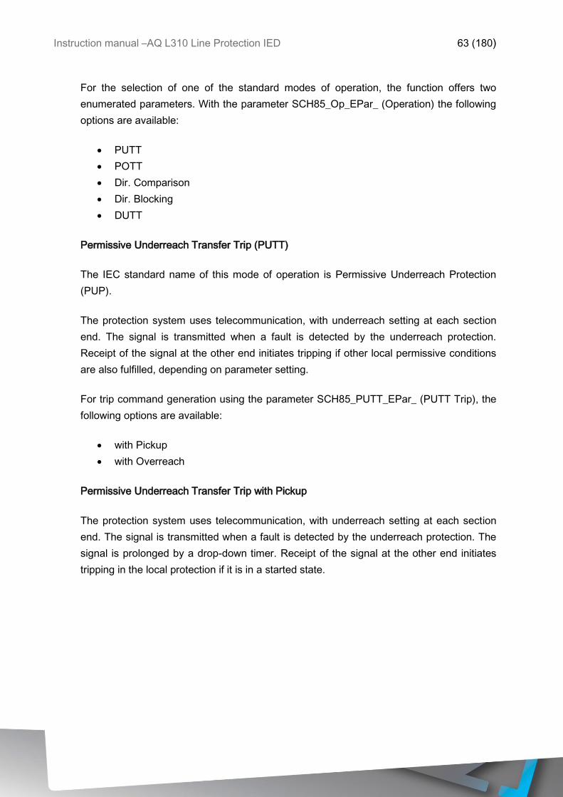
Instruction manual –AQ L310 Line Protection IED 63 (180)
For the selection of one of the standard modes of operation, the function offers two
enumerated parameters. With the parameter SCH85_Op_EPar_ (Operation) the following
options are available:
PUTT
POTT
Dir. Comparison
Dir. Blocking
DUTT
Permissive Underreach Transfer Trip (PUTT)
The IEC standard name of this mode of operation is Permissive Underreach Protection
(PUP).
The protection system uses telecommunication, with underreach setting at each section
end. The signal is transmitted when a fault is detected by the underreach protection.
Receipt of the signal at the other end initiates tripping if other local permissive conditions
are also fulfilled, depending on parameter setting.
For trip command generation using the parameter SCH85_PUTT_EPar_ (PUTT Trip), the
following options are available:
with Pickup
with Overreach
Permissive Underreach Transfer Trip with Pickup
The protection system uses telecommunication, with underreach setting at each section
end. The signal is transmitted when a fault is detected by the underreach protection. The
signal is prolonged by a drop-down timer. Receipt of the signal at the other end initiates
tripping in the local protection if it is in a started state.
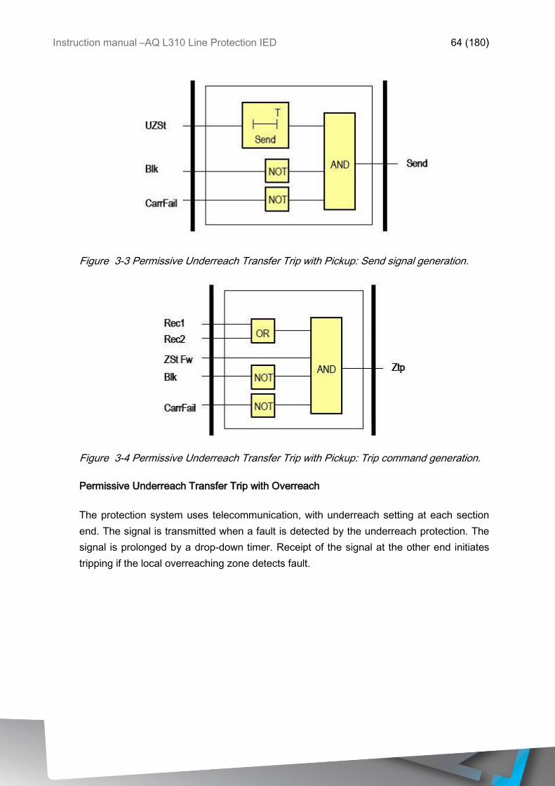
Instruction manual –AQ L310 Line Protection IED 64 (180)
Figure 3-3 Permissive Underreach Transfer Trip with Pickup: Send signal generation.
Figure 3-4 Permissive Underreach Transfer Trip with Pickup: Trip command generation.
Permissive Underreach Transfer Trip with Overreach
The protection system uses telecommunication, with underreach setting at each section
end. The signal is transmitted when a fault is detected by the underreach protection. The
signal is prolonged by a drop-down timer. Receipt of the signal at the other end initiates
tripping if the local overreaching zone detects fault.
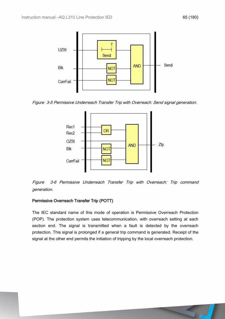
Instruction manual –AQ L310 Line Protection IED 65 (180)
Figure 3-5 Permissive Underreach Transfer Trip with Overreach: Send signal generation.
Figure 3-6 Permissive Underreach Transfer Trip with Overreach: Trip command
generation.
Permissive Overreach Transfer Trip (POTT)
The IEC standard name of this mode of operation is Permissive Overreach Protection
(POP). The protection system uses telecommunication, with overreach setting at each
section end. The signal is transmitted when a fault is detected by the overreach
protection. This signal is prolonged if a general trip command is generated. Receipt of the
signal at the other end permits the initiation of tripping by the local overreach protection.
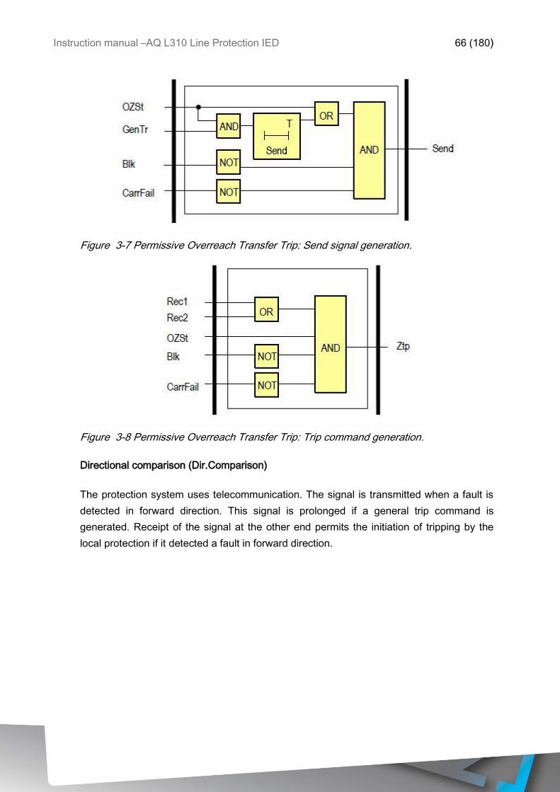
Instruction manual –AQ L310 Line Protection IED 66 (180)
Figure 3-7 Permissive Overreach Transfer Trip: Send signal generation.
Figure 3-8 Permissive Overreach Transfer Trip: Trip command generation.
Directional comparison (Dir.Comparison)
The protection system uses telecommunication. The signal is transmitted when a fault is
detected in forward direction. This signal is prolonged if a general trip command is
generated. Receipt of the signal at the other end permits the initiation of tripping by the
local protection if it detected a fault in forward direction.
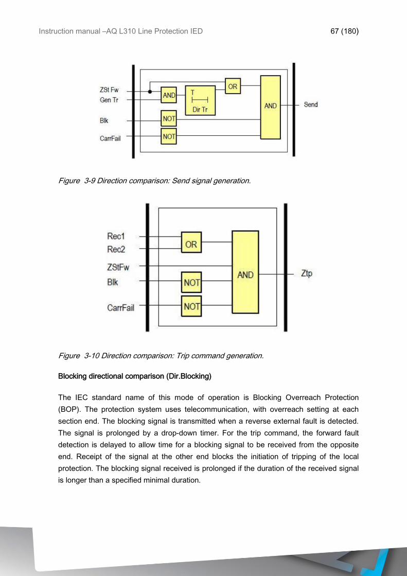
Instruction manual –AQ L310 Line Protection IED 67 (180)
Figure 3-9 Direction comparison: Send signal generation.
Figure 3-10 Direction comparison: Trip command generation.
Blocking directional comparison (Dir.Blocking)
The IEC standard name of this mode of operation is Blocking Overreach Protection
(BOP). The protection system uses telecommunication, with overreach setting at each
section end. The blocking signal is transmitted when a reverse external fault is detected.
The signal is prolonged by a drop-down timer. For the trip command, the forward fault
detection is delayed to allow time for a blocking signal to be received from the opposite
end. Receipt of the signal at the other end blocks the initiation of tripping of the local
protection. The blocking signal received is prolonged if the duration of the received signal
is longer than a specified minimal duration.
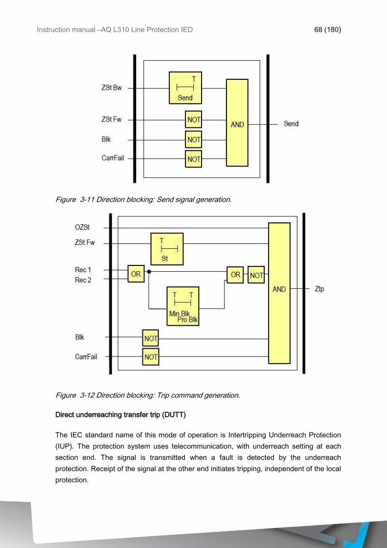
Instruction manual –AQ L310 Line Protection IED 68 (180)
Figure 3-11 Direction blocking: Send signal generation.
Figure 3-12 Direction blocking: Trip command generation.
Direct underreaching transfer trip (DUTT)
The IEC standard name of this mode of operation is Intertripping Underreach Protection
(IUP). The protection system uses telecommunication, with underreach setting at each
section end. The signal is transmitted when a fault is detected by the underreach
protection. Receipt of the signal at the other end initiates tripping, independent of the local
protection.
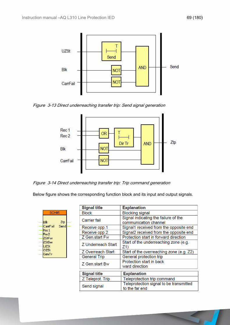
Instruction manual –AQ L310 Line Protection IED 69 (180)
Figure 3-13 Direct underreaching transfer trip: Send signal generation
Figure 3-14 Direct underreaching transfer trip: Trip command generation
Below figure shows the corresponding function block and its input and output signals.
Instruction manual –AQ L310 Line Protection IED 70 (180)
Table 3-24 Setting parameters of the teleprotection function
Parameter Setting value, range
and step
Description
Operation Off
PUTT
POTT
Dir.comparison
Dir.blocking
DUTT
Operating mode of the function. Default setting is Off.
PUTT trip with Pickup
with Overreach
Tripping command generation setting. Default setting with
Overreach.
Send prolong
time
1…10000 ms by step
of 1 ms
Setting for prolonging the teleprotection signal on the sending
end. Default setting 10 ms.
Direct Trip
delay PUTT
1…10000 ms by step
of 1 ms
Setting for direct trip delay for PUTT function. Default setting
10 ms.
Z start delay
(block)
1…10000 ms by step
of 1 ms
Setting for under impedance start delay. Default setting 10 ms.
Min.Block time 1…10000 ms by step
of 1 ms
Setting for minimum block time for the teleprotection. Default
setting 10 ms.
Prolong Block
time
1…10000 ms by step
of 1 ms
Setting for prolonging the blocked time of teleprotection
function. Default setting 10 ms.
3.2.3 THREE-PHASE INSTANTANEOUS OVERCURRENT I>>> (50)
The instantaneous overcurrent protection function operates according to instantaneous
characteristics, using the three sampled phase currents. The setting value is a parameter,
and it can be doubled with dedicated input binary signal. The basic calculation can be
based on peak value selection or on Fourier basic harmonic calculation, according to the
parameter setting.
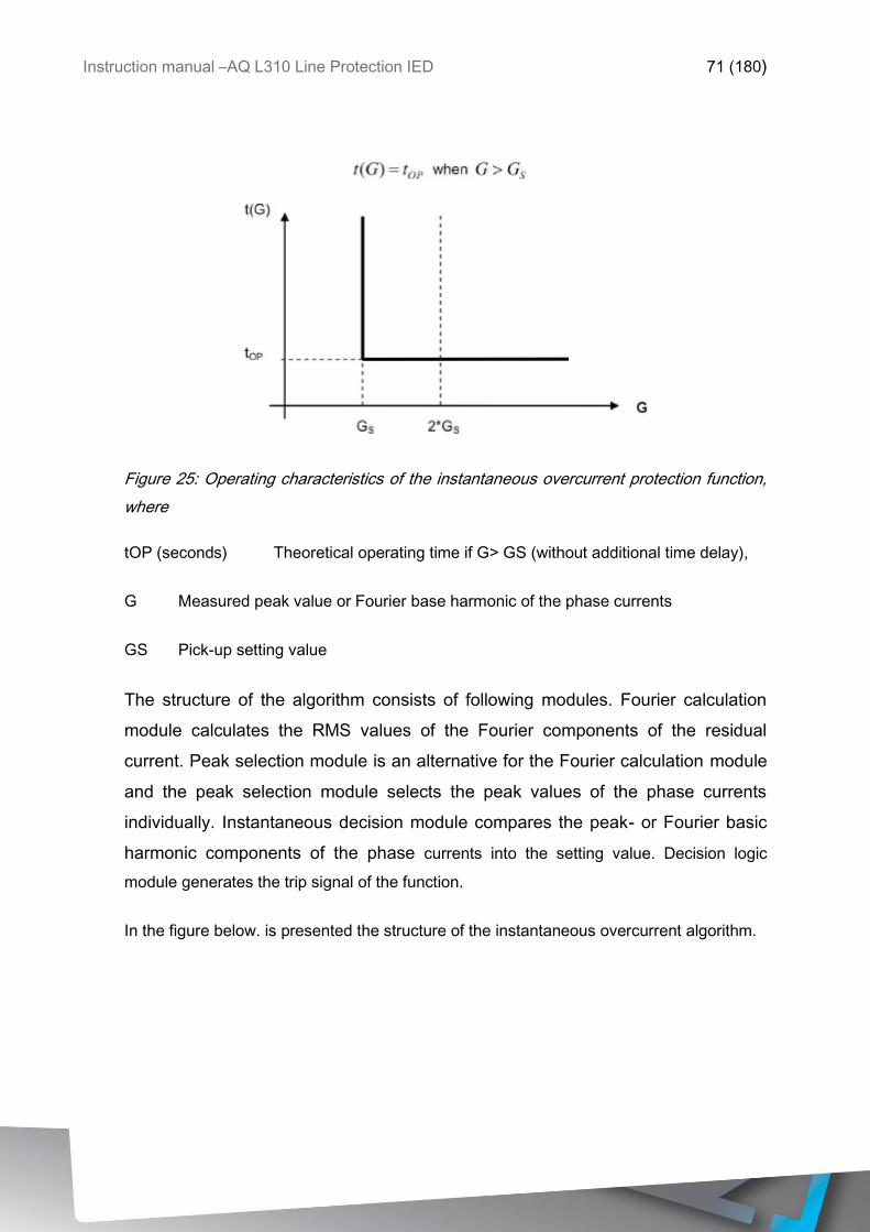
Instruction manual –AQ L310 Line Protection IED 71 (180)
Figure 25: Operating characteristics of the instantaneous overcurrent protection function,
where
tOP (seconds) Theoretical operating time if G> GS (without additional time delay),
G Measured peak value or Fourier base harmonic of the phase currents
GS Pick-up setting value
The structure of the algorithm consists of following modules. Fourier calculation
module calculates the RMS values of the Fourier components of the residual
current. Peak selection module is an alternative for the Fourier calculation module
and the peak selection module selects the peak values of the phase currents
individually. Instantaneous decision module compares the peak- or Fourier basic
harmonic components of the phase currents into the setting value. Decision logic
module generates the trip signal of the function.
In the figure below. is presented the structure of the instantaneous overcurrent algorithm.
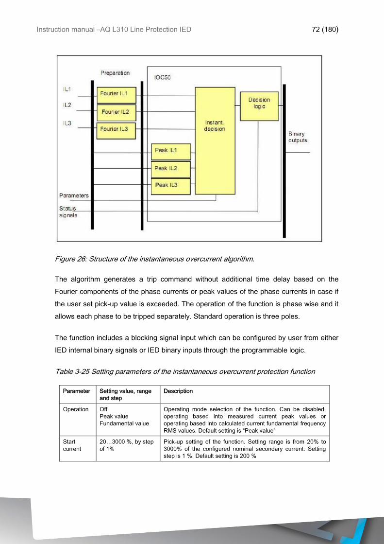
Instruction manual –AQ L310 Line Protection IED 72 (180)
Figure 26: Structure of the instantaneous overcurrent algorithm.
The algorithm generates a trip command without additional time delay based on the
Fourier components of the phase currents or peak values of the phase currents in case if
the user set pick-up value is exceeded. The operation of the function is phase wise and it
allows each phase to be tripped separately. Standard operation is three poles.
The function includes a blocking signal input which can be configured by user from either
IED internal binary signals or IED binary inputs through the programmable logic.
Table 3-25 Setting parameters of the instantaneous overcurrent protection function
Parameter Setting value, range
and step
Description
Operation Off
Peak value
Fundamental value
Operating mode selection of the function. Can be disabled,
operating based into measured current peak values or
operating based into calculated current fundamental frequency
RMS values. Default setting is “Peak value”
Start
current
20…3000 %, by step
of 1%
Pick-up setting of the function. Setting range is from 20% to
3000% of the configured nominal secondary current. Setting
step is 1 %. Default setting is 200 %
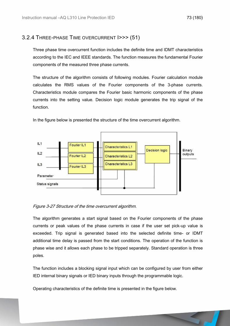
Instruction manual –AQ L310 Line Protection IED 73 (180)
3.2.4 THREE-PHASE TIME OVERCURRENT I>>> (51)
Three phase time overcurrent function includes the definite time and IDMT characteristics
according to the IEC and IEEE standards. The function measures the fundamental Fourier
components of the measured three phase currents.
The structure of the algorithm consists of following modules. Fourier calculation module
calculates the RMS values of the Fourier components of the 3-phase currents.
Characteristics module compares the Fourier basic harmonic components of the phase
currents into the setting value. Decision logic module generates the trip signal of the
function.
In the figure below is presented the structure of the time overcurrent algorithm.
Figure 3-27 Structure of the time overcurrent algorithm.
The algorithm generates a start signal based on the Fourier components of the phase
currents or peak values of the phase currents in case if the user set pick-up value is
exceeded. Trip signal is generated based into the selected definite time- or IDMT
additional time delay is passed from the start conditions. The operation of the function is
phase wise and it allows each phase to be tripped separately. Standard operation is three
poles.
The function includes a blocking signal input which can be configured by user from either
IED internal binary signals or IED binary inputs through the programmable logic.
Operating characteristics of the definite time is presented in the figure below.
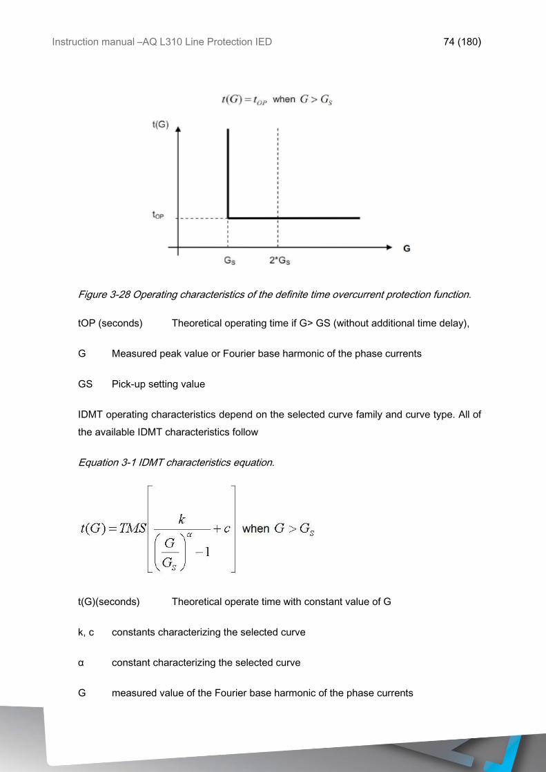
Instruction manual –AQ L310 Line Protection IED 74 (180)
Figure 3-28 Operating characteristics of the definite time overcurrent protection function.
tOP (seconds) Theoretical operating time if G> GS (without additional time delay),
G Measured peak value or Fourier base harmonic of the phase currents
GS Pick-up setting value
IDMT operating characteristics depend on the selected curve family and curve type. All of
the available IDMT characteristics follow
Equation 3-1 IDMT characteristics equation.
t(G)(seconds) Theoretical operate time with constant value of G
k, c constants characterizing the selected curve
α constant characterizing the selected curve
G measured value of the Fourier base harmonic of the phase currents
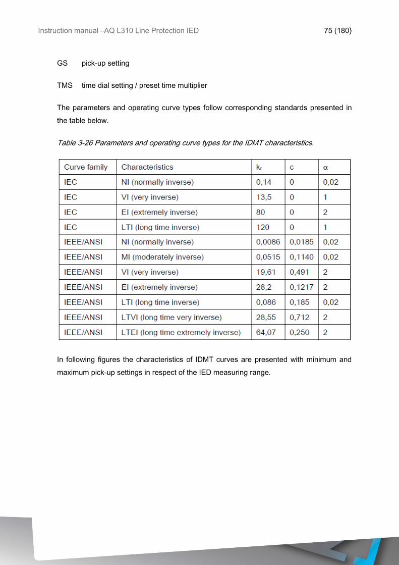
Instruction manual –AQ L310 Line Protection IED 75 (180)
GS pick-up setting
TMS time dial setting / preset time multiplier
The parameters and operating curve types follow corresponding standards presented in
the table below.
Table 3-26 Parameters and operating curve types for the IDMT characteristics.
In following figures the characteristics of IDMT curves are presented with minimum and
maximum pick-up settings in respect of the IED measuring range.
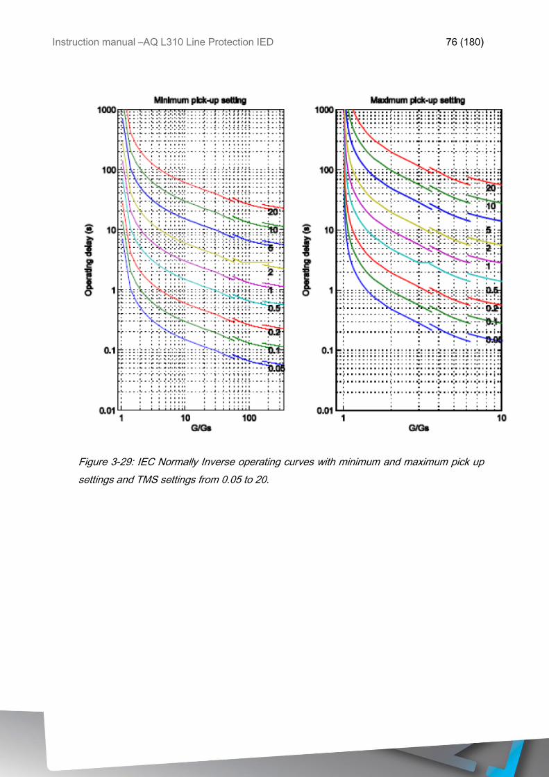
Instruction manual –AQ L310 Line Protection IED 76 (180)
Figure 3-29: IEC Normally Inverse operating curves with minimum and maximum pick up
settings and TMS settings from 0.05 to 20.
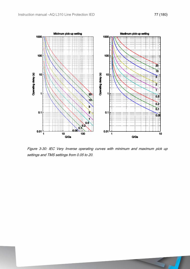
Instruction manual –AQ L310 Line Protection IED 77 (180)
Figure 3-30: IEC Very Inverse operating curves with minimum and maximum pick up
settings and TMS settings from 0.05 to 20.
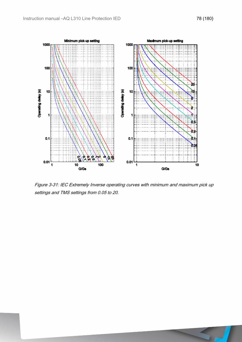
Instruction manual –AQ L310 Line Protection IED 78 (180)
Figure 3-31: IEC Extremely Inverse operating curves with minimum and maximum pick up
settings and TMS settings from 0.05 to 20.
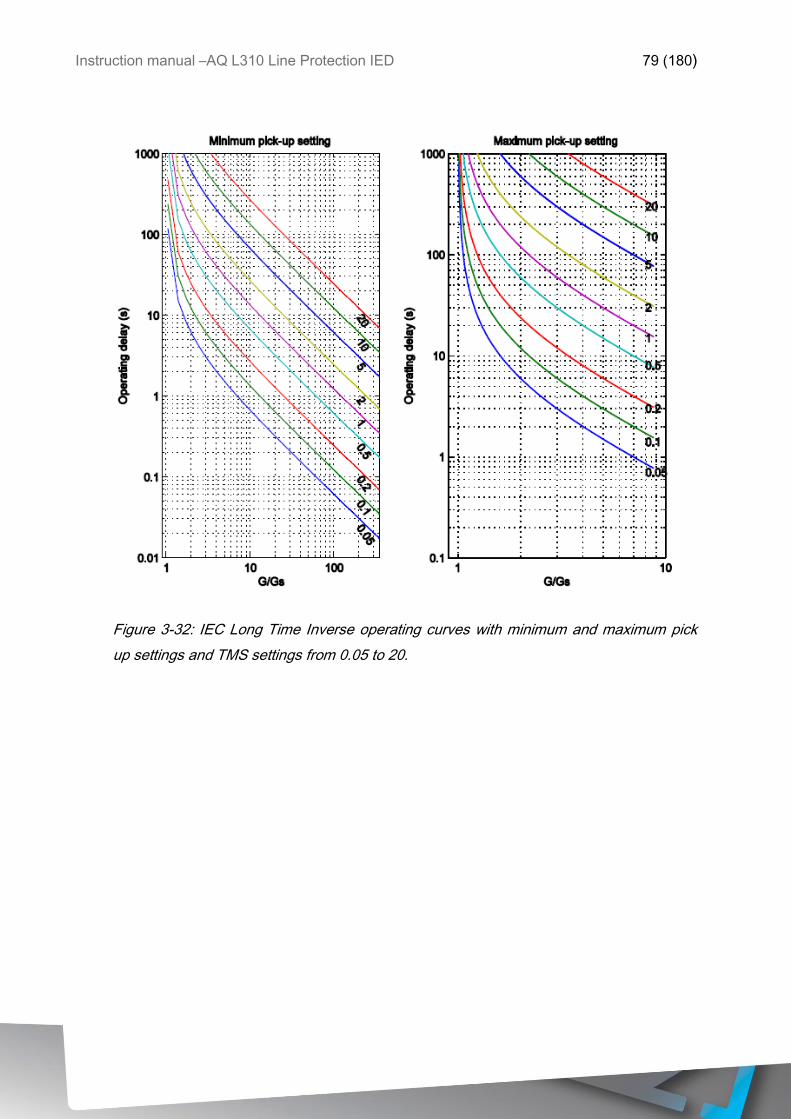
Instruction manual –AQ L310 Line Protection IED 79 (180)
Figure 3-32: IEC Long Time Inverse operating curves with minimum and maximum pick
up settings and TMS settings from 0.05 to 20.
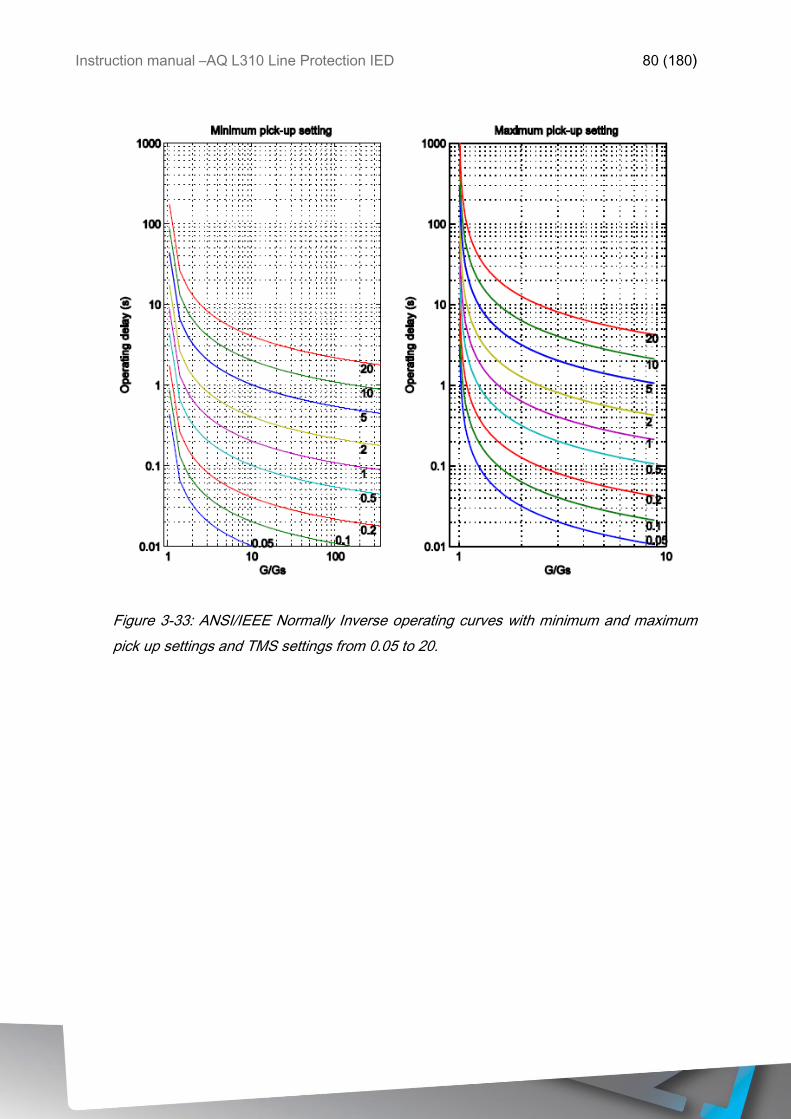
Instruction manual –AQ L310 Line Protection IED 80 (180)
Figure 3-33: ANSI/IEEE Normally Inverse operating curves with minimum and maximum
pick up settings and TMS settings from 0.05 to 20.
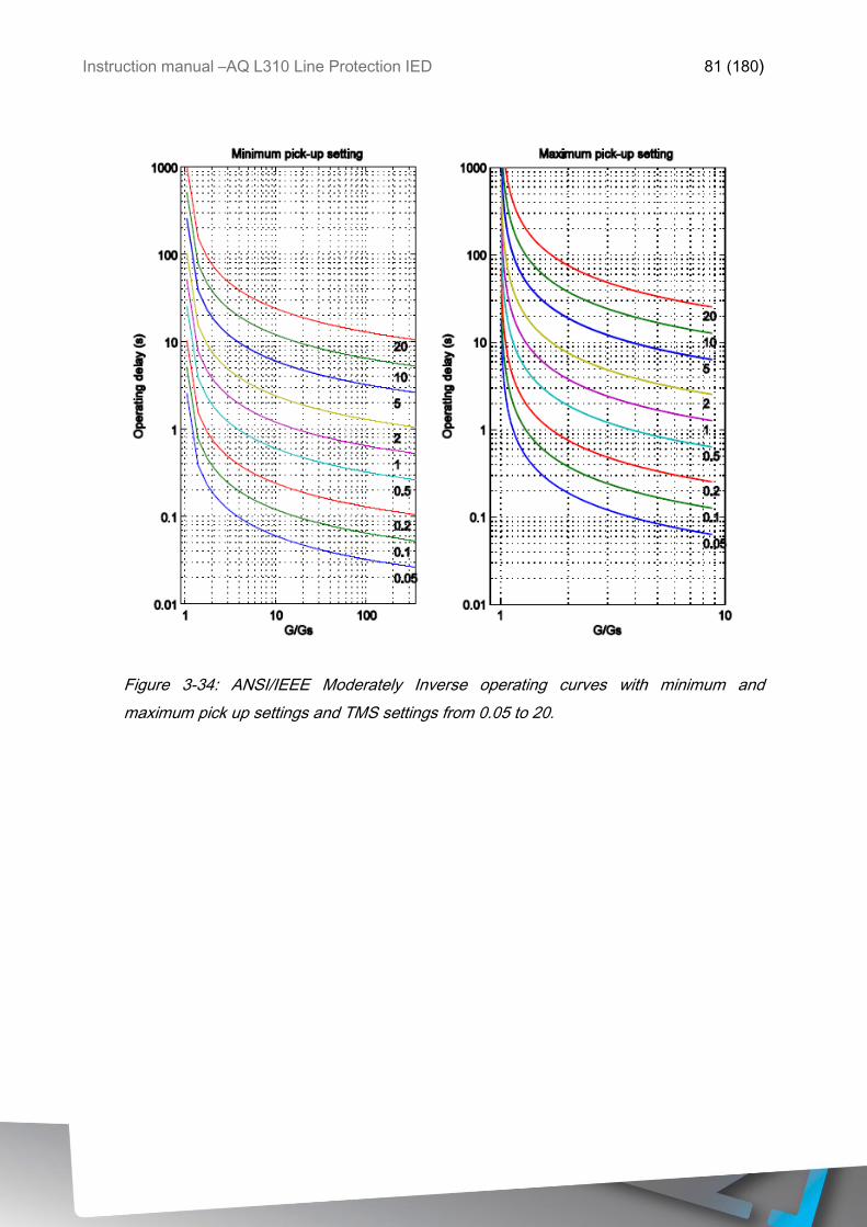
Instruction manual –AQ L310 Line Protection IED 81 (180)
Figure 3-34: ANSI/IEEE Moderately Inverse operating curves with minimum and
maximum pick up settings and TMS settings from 0.05 to 20.
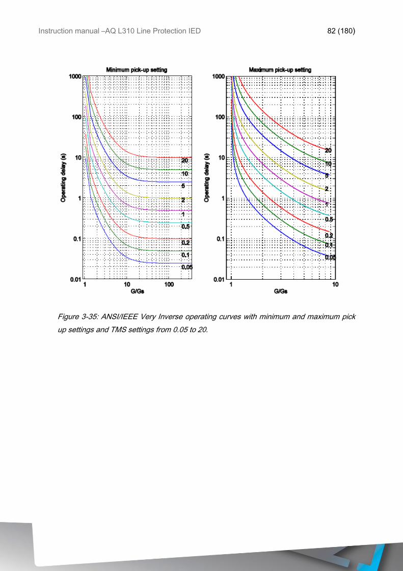
Instruction manual –AQ L310 Line Protection IED 82 (180)
Figure 3-35: ANSI/IEEE Very Inverse operating curves with minimum and maximum pick
up settings and TMS settings from 0.05 to 20.

Instruction manual –AQ L310 Line Protection IED 83 (180)
Figure 3-36: ANSI/IEEE Extremely Inverse operating curves with minimum and maximum
pick up settings and TMS settings from 0.05 to 20.
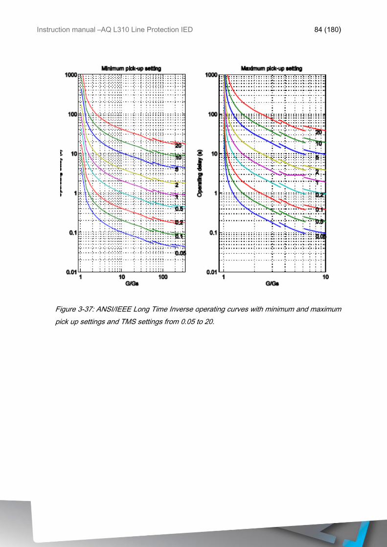
Instruction manual –AQ L310 Line Protection IED 84 (180)
Figure 3-37: ANSI/IEEE Long Time Inverse operating curves with minimum and maximum
pick up settings and TMS settings from 0.05 to 20.
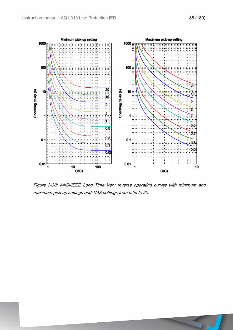
Instruction manual –AQ L310 Line Protection IED 85 (180)
Figure 3-38: ANSI/IEEE Long Time Very Inverse operating curves with minimum and
maximum pick up settings and TMS settings from 0.05 to 20.
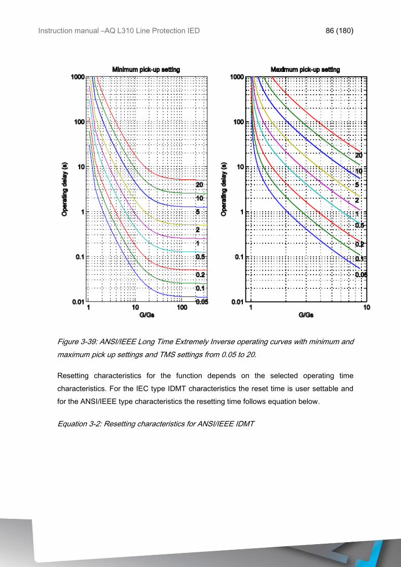
Instruction manual –AQ L310 Line Protection IED 86 (180)
Figure 3-39: ANSI/IEEE Long Time Extremely Inverse operating curves with minimum and
maximum pick up settings and TMS settings from 0.05 to 20.
Resetting characteristics for the function depends on the selected operating time
characteristics. For the IEC type IDMT characteristics the reset time is user settable and
for the ANSI/IEEE type characteristics the resetting time follows equation below.
Equation 3-2: Resetting characteristics for ANSI/IEEE IDMT
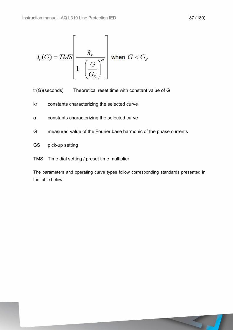
Instruction manual –AQ L310 Line Protection IED 87 (180)
tr(G)(seconds) Theoretical reset time with constant value of G
kr constants characterizing the selected curve
α constants characterizing the selected curve
G measured value of the Fourier base harmonic of the phase currents
GS pick-up setting
TMS Time dial setting / preset time multiplier
The parameters and operating curve types follow corresponding standards presented in
the table below.
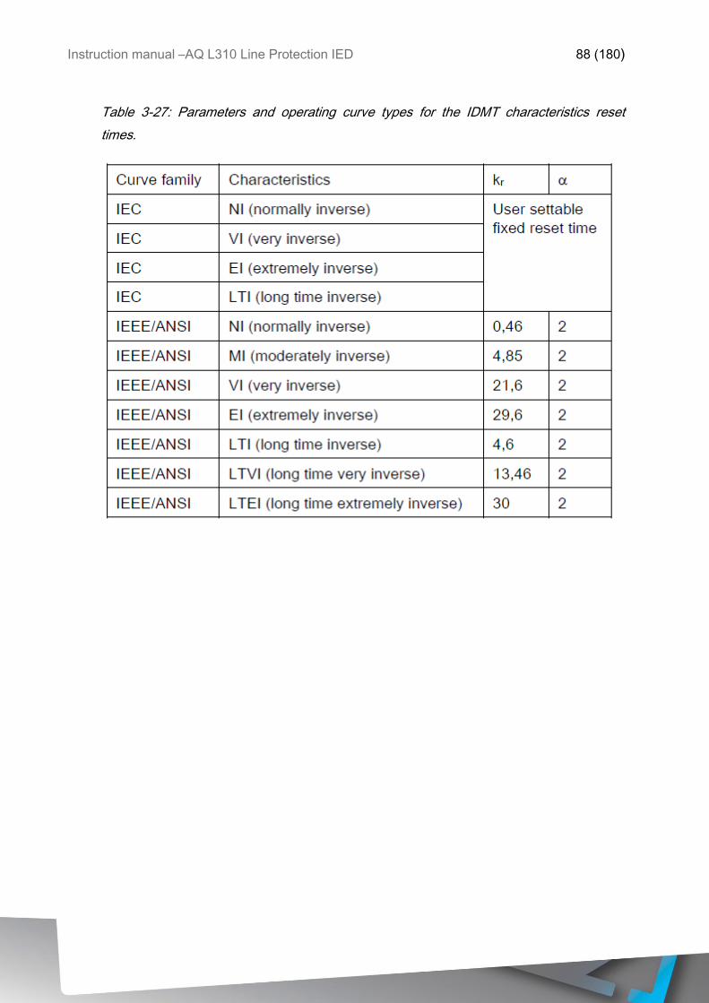
Instruction manual –AQ L310 Line Protection IED 88 (180)
Table 3-27: Parameters and operating curve types for the IDMT characteristics reset
times.
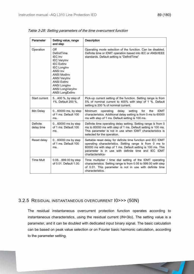
Instruction manual –AQ L310 Line Protection IED 89 (180)
Table 3-28: Setting parameters of the time overcurrent function
Parameter Setting value, range
and step
Description
Operation Off
DefinitTime
IEC Inv
IEC VeryInv
IEC ExtInv
IEC LongInv
ANSI Inv
ANSI ModInv
ANSI VeryInv
ANSI ExtInv
ANSI LongInv
ANSI LongVeryInv
ANSI LongExtInv
Operating mode selection of the function. Can be disabled,
Definite time or IDMT operation based into IEC or ANSI/IEEE
standards. Default setting is “DefinitTime”
Start current 5…400 %, by step of
1%. Default 200 %.
Pick-up current setting of the function. Setting range is from
5% of nominal current to 400% with step of 1 %. Default
setting is 200 % of nominal current.
Min Delay 0…60000 ms, by step
of 1 ms. Default 100
ms.
Minimum operating delay setting for the IDMT
characteristics. Additional delay setting is from 0 ms to 60000
ms with step of 1 ms. Default setting is 100 ms.
Definite
delay time
0…60000 ms by step
of 1 ms. Default 100
ms.
Definite time operating delay setting. Setting range is from 0
ms to 60000 ms with step of 1 ms. Default setting is 100 ms.
This parameter is not in use when IDMT characteristics is
selected for the operation.
Reset delay 0…60000 ms by step
of 1 ms. Default 100
ms.
Settable reset delay for definite time function and IEC IDMT
operating characteristics. Setting range is from 0 ms to
60000 ms with step of 1 ms. Default setting is 100 ms. This
parameter is in use with definite time and IEC IDMT
chartacteristics-
Time Mult 0.05…999.00 by step
of 0.01. Default 1.00.
Time multiplier / time dial setting of the IDMT operating
characteristics. Setting range is from 0.05 to 999.00 with step
of 0.01. This parameter is not in use with definite time
characteristics.
3.2.5 RESIDUAL INSTANTANEOUS OVERCURRENT I0>>> (50N)
The residual instantaneous overcurrent protection function operates according to
instantaneous characteristics, using the residual current (IN=3Io). The setting value is a
parameter, and it can be doubled with dedicated input binary signal. The basic calculation
can be based on peak value selection or on Fourier basic harmonic calculation, according
to the parameter setting.
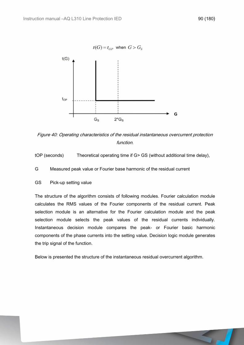
Instruction manual –AQ L310 Line Protection IED 90 (180)
Figure 40: Operating characteristics of the residual instantaneous overcurrent protection
function.
tOP (seconds) Theoretical operating time if G> GS (without additional time delay),
G Measured peak value or Fourier base harmonic of the residual current
GS Pick-up setting value
The structure of the algorithm consists of following modules. Fourier calculation module
calculates the RMS values of the Fourier components of the residual current. Peak
selection module is an alternative for the Fourier calculation module and the peak
selection module selects the peak values of the residual currents individually.
Instantaneous decision module compares the peak- or Fourier basic harmonic
components of the phase currents into the setting value. Decision logic module generates
the trip signal of the function.
Below is presented the structure of the instantaneous residual overcurrent algorithm.
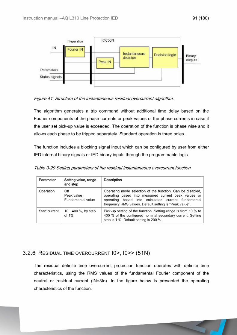
Instruction manual –AQ L310 Line Protection IED 91 (180)
Figure 41: Structure of the instantaneous residual overcurrent algorithm.
The algorithm generates a trip command without additional time delay based on the
Fourier components of the phase currents or peak values of the phase currents in case if
the user set pick-up value is exceeded. The operation of the function is phase wise and it
allows each phase to be tripped separately. Standard operation is three poles.
The function includes a blocking signal input which can be configured by user from either
IED internal binary signals or IED binary inputs through the programmable logic.
Table 3-29 Setting parameters of the residual instantaneous overcurrent function
Parameter Setting value, range
and step
Description
Operation Off
Peak value
Fundamental value
Operating mode selection of the function. Can be disabled,
operating based into measured current peak values or
operating based into calculated current fundamental
frequency RMS values. Default setting is “Peak value”.
Start current 10…400 %, by step
of 1%
Pick-up setting of the function. Setting range is from 10 % to
400 % of the configured nominal secondary current. Setting
step is 1 %. Default setting is 200 %.
3.2.6 RESIDUAL TIME OVERCURRENT I0>, I0>> (51N)
The residual definite time overcurrent protection function operates with definite time
characteristics, using the RMS values of the fundamental Fourier component of the
neutral or residual current (IN=3Io). In the figure below is presented the operating
characteristics of the function.
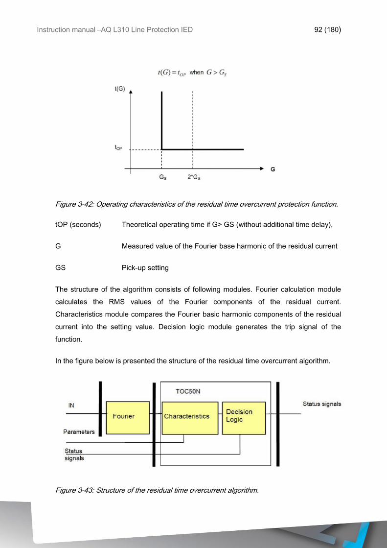
Instruction manual –AQ L310 Line Protection IED 92 (180)
Figure 3-42: Operating characteristics of the residual time overcurrent protection function.
tOP (seconds) Theoretical operating time if G> GS (without additional time delay),
G Measured value of the Fourier base harmonic of the residual current
GS Pick-up setting
The structure of the algorithm consists of following modules. Fourier calculation module
calculates the RMS values of the Fourier components of the residual current.
Characteristics module compares the Fourier basic harmonic components of the residual
current into the setting value. Decision logic module generates the trip signal of the
function.
In the figure below is presented the structure of the residual time overcurrent algorithm.
Figure 3-43: Structure of the residual time overcurrent algorithm.
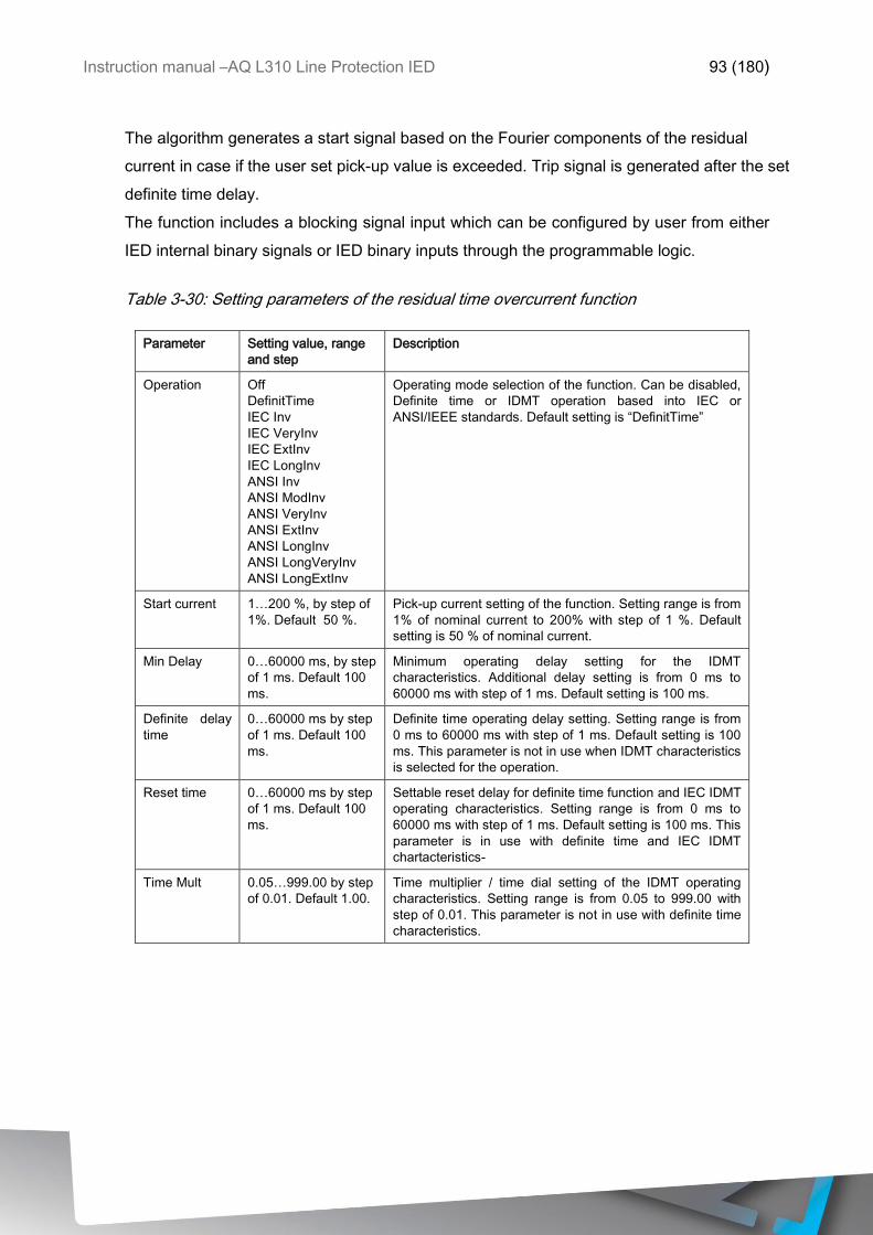
Instruction manual –AQ L310 Line Protection IED 93 (180)
The algorithm generates a start signal based on the Fourier components of the residual
current in case if the user set pick-up value is exceeded. Trip signal is generated after the set
definite time delay.
The function includes a blocking signal input which can be configured by user from either
IED internal binary signals or IED binary inputs through the programmable logic.
Table 3-30: Setting parameters of the residual time overcurrent function
Parameter Setting value, range
and step
Description
Operation Off
DefinitTime
IEC Inv
IEC VeryInv
IEC ExtInv
IEC LongInv
ANSI Inv
ANSI ModInv
ANSI VeryInv
ANSI ExtInv
ANSI LongInv
ANSI LongVeryInv
ANSI LongExtInv
Operating mode selection of the function. Can be disabled,
Definite time or IDMT operation based into IEC or
ANSI/IEEE standards. Default setting is “DefinitTime”
Start current 1…200 %, by step of
1%. Default 50 %.
Pick-up current setting of the function. Setting range is from
1% of nominal current to 200% with step of 1 %. Default
setting is 50 % of nominal current.
Min Delay 0…60000 ms, by step
of 1 ms. Default 100
ms.
Minimum operating delay setting for the IDMT
characteristics. Additional delay setting is from 0 ms to
60000 ms with step of 1 ms. Default setting is 100 ms.
Definite delay
time
0…60000 ms by step
of 1 ms. Default 100
ms.
Definite time operating delay setting. Setting range is from
0 ms to 60000 ms with step of 1 ms. Default setting is 100
ms. This parameter is not in use when IDMT characteristics
is selected for the operation.
Reset time 0…60000 ms by step
of 1 ms. Default 100
ms.
Settable reset delay for definite time function and IEC IDMT
operating characteristics. Setting range is from 0 ms to
60000 ms with step of 1 ms. Default setting is 100 ms. This
parameter is in use with definite time and IEC IDMT
chartacteristics-
Time Mult 0.05…999.00 by step
of 0.01. Default 1.00.
Time multiplier / time dial setting of the IDMT operating
characteristics. Setting range is from 0.05 to 999.00 with
step of 0.01. This parameter is not in use with definite time
characteristics.
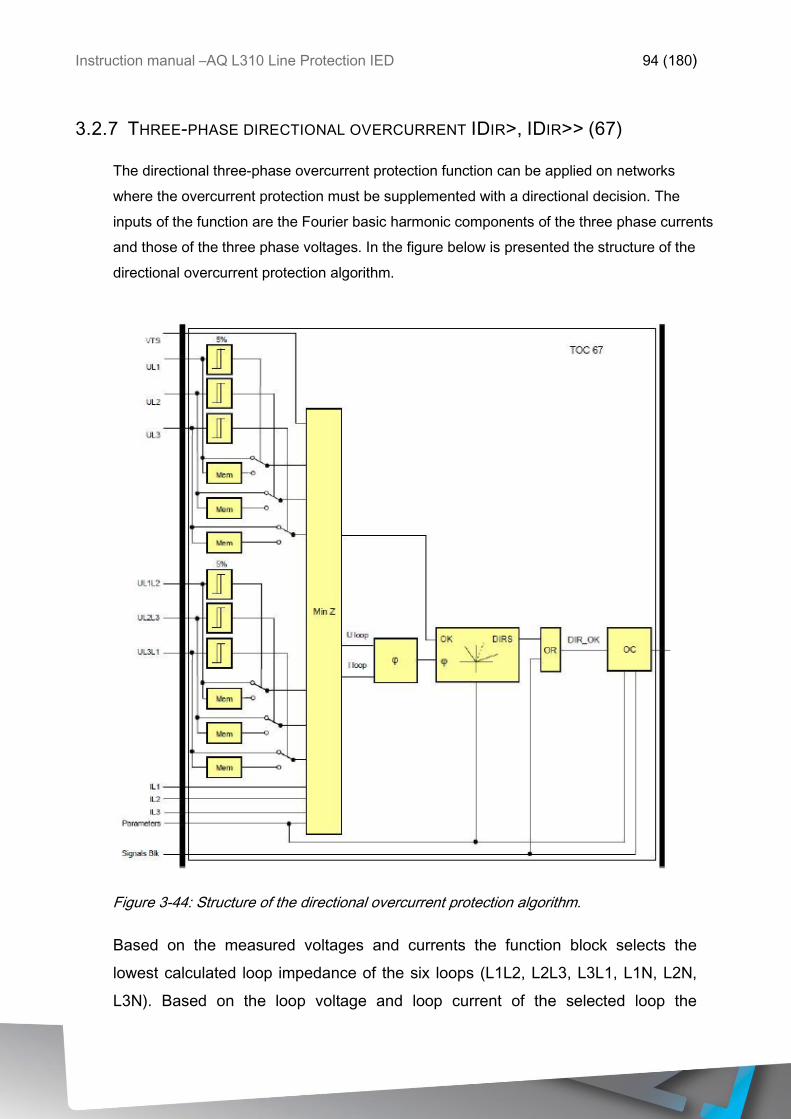
Instruction manual –AQ L310 Line Protection IED 94 (180)
3.2.7 THREE-PHASE DIRECTIONAL OVERCURRENT IDIR>, IDIR>> (67)
The directional three-phase overcurrent protection function can be applied on networks
where the overcurrent protection must be supplemented with a directional decision. The
inputs of the function are the Fourier basic harmonic components of the three phase currents
and those of the three phase voltages. In the figure below is presented the structure of the
directional overcurrent protection algorithm.
Figure 3-44: Structure of the directional overcurrent protection algorithm.
Based on the measured voltages and currents the function block selects the
lowest calculated loop impedance of the six loops (L1L2, L2L3, L3L1, L1N, L2N,
L3N). Based on the loop voltage and loop current of the selected loop the
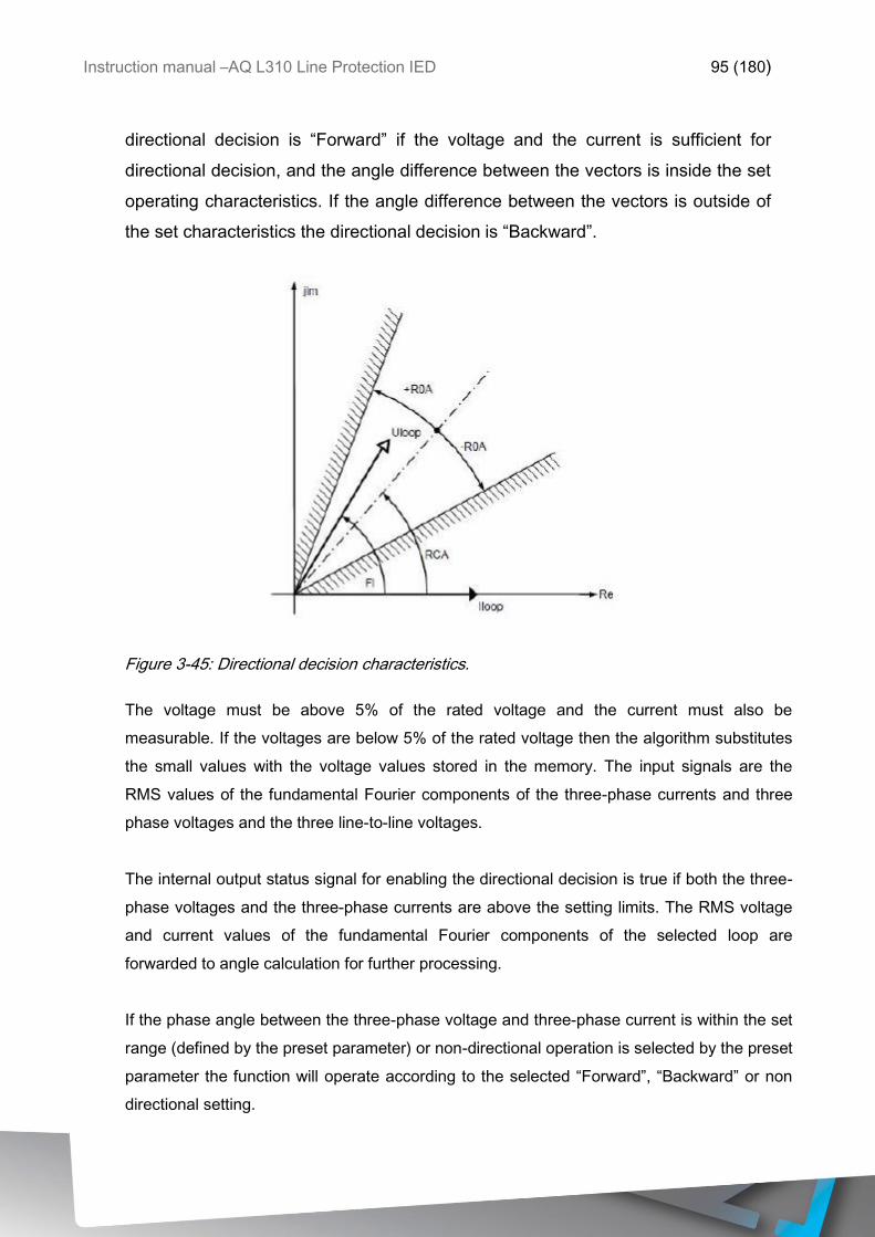
Instruction manual –AQ L310 Line Protection IED 95 (180)
directional decision is “Forward” if the voltage and the current is sufficient for
directional decision, and the angle difference between the vectors is inside the set
operating characteristics. If the angle difference between the vectors is outside of
the set characteristics the directional decision is “Backward”.
Figure 3-45: Directional decision characteristics.
The voltage must be above 5% of the rated voltage and the current must also be
measurable. If the voltages are below 5% of the rated voltage then the algorithm substitutes
the small values with the voltage values stored in the memory. The input signals are the
RMS values of the fundamental Fourier components of the three-phase currents and three
phase voltages and the three line-to-line voltages.
The internal output status signal for enabling the directional decision is true if both the three-
phase voltages and the three-phase currents are above the setting limits. The RMS voltage
and current values of the fundamental Fourier components of the selected loop are
forwarded to angle calculation for further processing.
If the phase angle between the three-phase voltage and three-phase current is within the set
range (defined by the preset parameter) or non-directional operation is selected by the preset
parameter the function will operate according to the selected “Forward”, “Backward” or non
directional setting.
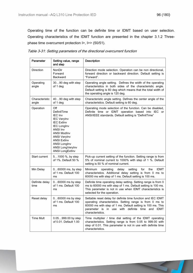
Instruction manual –AQ L310 Line Protection IED 96 (180)
Operating time of the function can be definite time or IDMT based on user selection.
Operating characteristics of the IDMT function are presented in the chapter 3.1.2 Three-
phase time overcurrent protection I>, I>> (50/51).
Table 3-31: Setting parameters of the directional overcurrent function
Parameter Setting value, range
and step
Description
Direction NonDir
Forward
Backward
Direction mode selection. Operation can be non directional,
forward direction or backward direction. Default setting is
“Forward”.
Operating
angle
30…90 deg with step
of 1 deg
Operating angle setting. Defines the width of the operating
characteristics in both sides of the characteristic angle.
Default setting is 60 deg which means that the total width of
the operating angle is 120 deg.
Characteristic
angle
40…90 deg with step
of 1 deg
Characteristic angle setting. Defines the center angle of the
characteristics. Default setting is 60 deg.
Operation Off
DefinitTime
IEC Inv
IEC VeryInv
IEC ExtInv
IEC LongInv
ANSI Inv
ANSI ModInv
ANSI VeryInv
ANSI ExtInv
ANSI LongInv
ANSI LongVeryInv
ANSI LongExtInv
Operating mode selection of the function. Can be disabled,
Definite time or IDMT operation based into IEC or
ANSI/IEEE standards. Default setting is “DefinitTime”
Start current 5…1000 %, by step
of 1%. Default 50 %
Pick-up current setting of the function. Setting range is from
5% of nominal current to 1000% with step of 1 %. Default
setting is 50 % of nominal current.
Min Delay 0…60000 ms, by step
of 1 ms. Default 100
ms
Minimum operating delay setting for the IDMT
characteristics. Additional delay setting is from 0 ms to
60000 ms with step of 1 ms. Default setting is 100 ms.
Definite delay
time
0…60000 ms by step
of 1 ms. Default 100
ms
Definite time operating delay setting. Setting range is from 0
ms to 60000 ms with step of 1 ms. Default setting is 100 ms.
This parameter is not in use when IDMT characteristics is
selected for the operation.
Reset delay 0…60000 ms by step
of 1 ms. Default 100
ms
Settable reset delay for definite time function and IEC IDMT
operating characteristics. Setting range is from 0 ms to
60000 ms with step of 1 ms. Default setting is 100 ms. This
parameter is in use with definite time and IDMT
characteristics.
Time Mult 0.05…999.00 by step
of 0.01. Default 1.00
Time multiplier / time dial setting of the IDMT operating
characteristics. Setting range is from 0.05 to 999.00 with
step of 0.01. This parameter is not in use with definite time
characteristics.
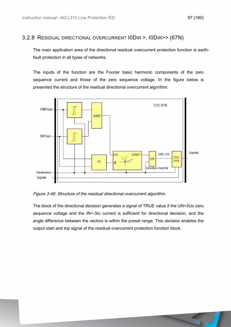
Instruction manual –AQ L310 Line Protection IED 97 (180)
3.2.8 RESIDUAL DIRECTIONAL OVERCURRENT I0DIR >, I0DIR>> (67N)
The main application area of the directional residual overcurrent protection function is earth-
fault protection in all types of networks.
The inputs of the function are the Fourier basic harmonic components of the zero
sequence current and those of the zero sequence voltage. In the figure below is
presented the structure of the residual directional overcurrent algorithm.
Figure 3-46: Structure of the residual directional overcurrent algorithm.
The block of the directional decision generates a signal of TRUE value if the UN=3Uo zero
sequence voltage and the IN=-3Io current is sufficient for directional decision, and the
angle difference between the vectors is within the preset range. This decision enables the
output start and trip signal of the residual overcurrent protection function block.
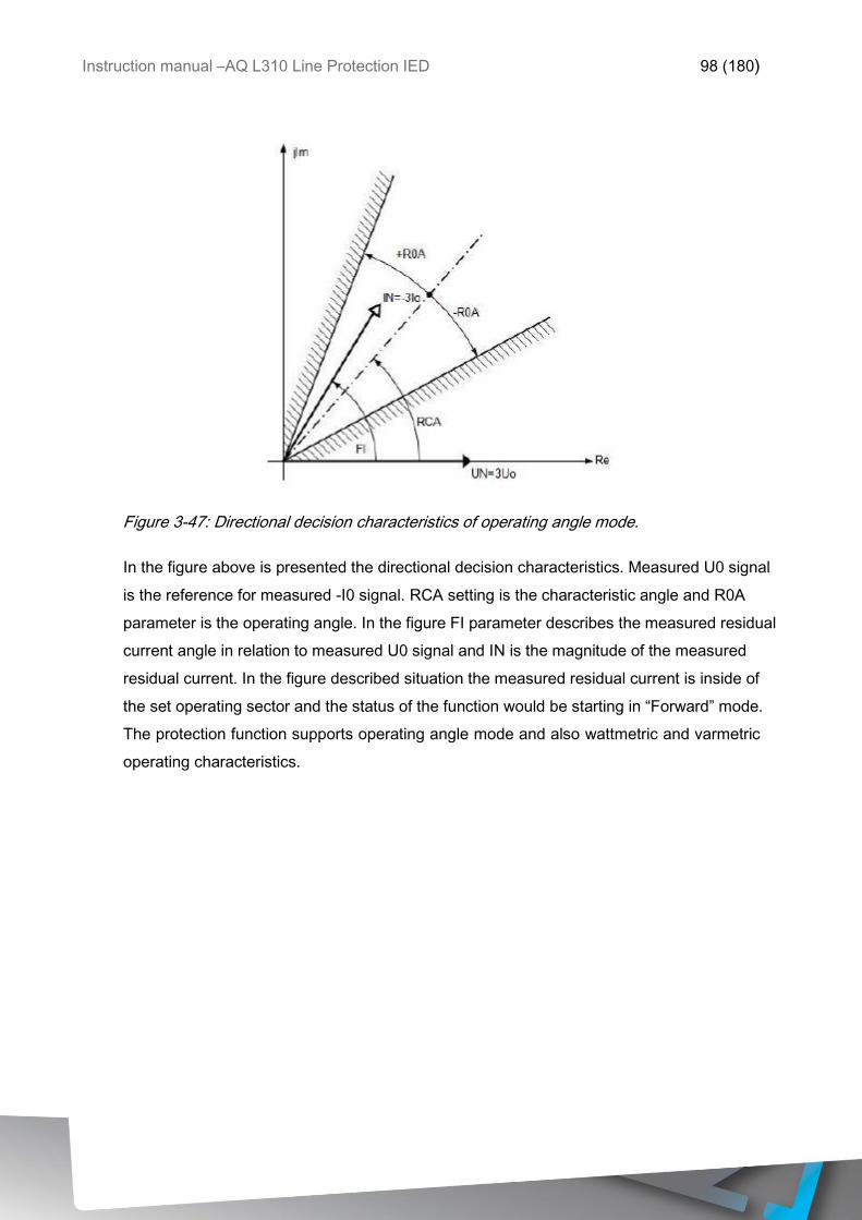
Instruction manual –AQ L310 Line Protection IED 98 (180)
Figure 3-47: Directional decision characteristics of operating angle mode.
In the figure above is presented the directional decision characteristics. Measured U0 signal
is the reference for measured -I0 signal. RCA setting is the characteristic angle and R0A
parameter is the operating angle. In the figure FI parameter describes the measured residual
current angle in relation to measured U0 signal and IN is the magnitude of the measured
residual current. In the figure described situation the measured residual current is inside of
the set operating sector and the status of the function would be starting in “Forward” mode.
The protection function supports operating angle mode and also wattmetric and varmetric
operating characteristics.
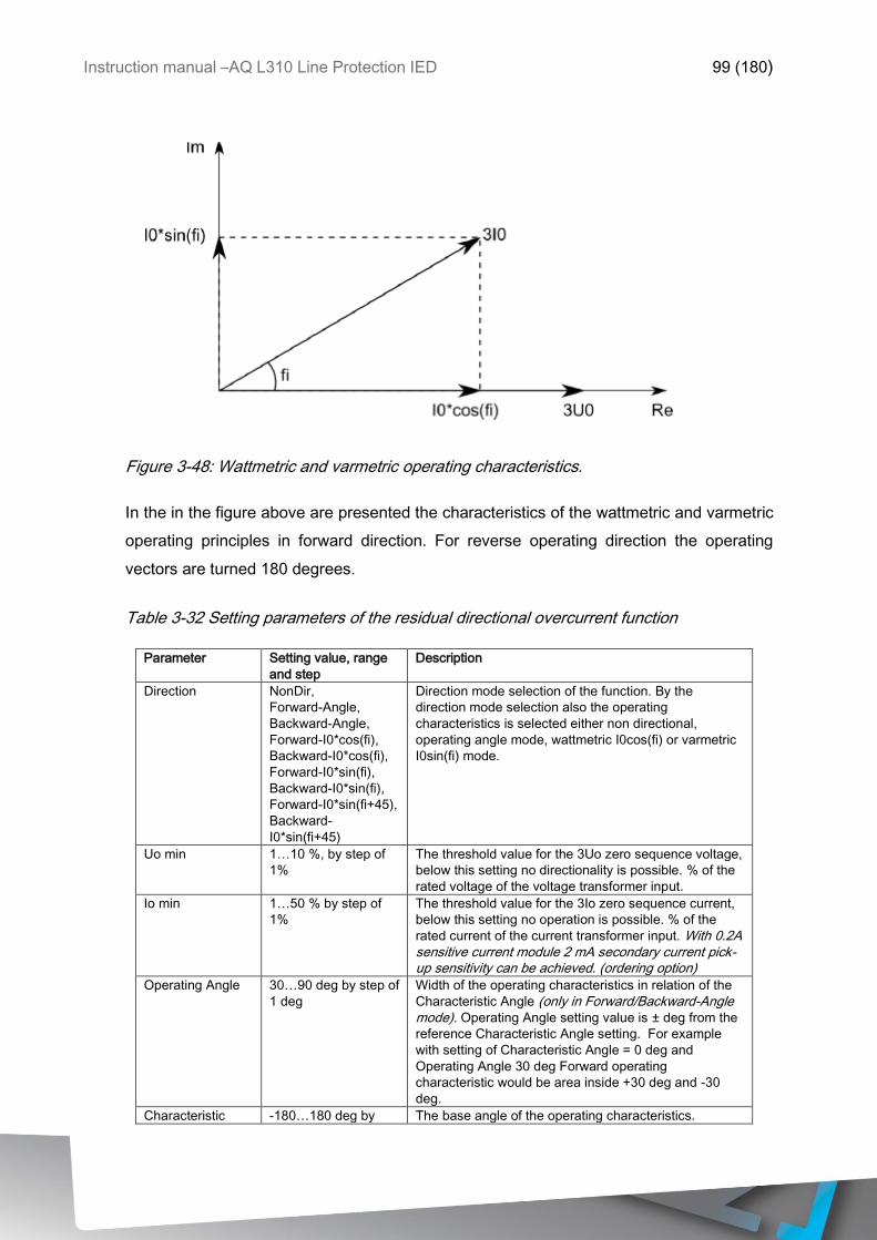
Instruction manual –AQ L310 Line Protection IED 99 (180)
Figure 3-48: Wattmetric and varmetric operating characteristics.
In the in the figure above are presented the characteristics of the wattmetric and varmetric
operating principles in forward direction. For reverse operating direction the operating
vectors are turned 180 degrees.
Table 3-32 Setting parameters of the residual directional overcurrent function
Parameter Setting value, range
and step
Description
Direction NonDir,
Forward-Angle,
Backward-Angle,
Forward-I0*cos(fi),
Backward-I0*cos(fi),
Forward-I0*sin(fi),
Backward-I0*sin(fi),
Forward-I0*sin(fi+45),
Backward-
I0*sin(fi+45)
Direction mode selection of the function. By the
direction mode selection also the operating
characteristics is selected either non directional,
operating angle mode, wattmetric I0cos(fi) or varmetric
I0sin(fi) mode.
Uo min 1…10 %, by step of
1%
The threshold value for the 3Uo zero sequence voltage,
below this setting no directionality is possible. % of the
rated voltage of the voltage transformer input.
Io min 1…50 % by step of
1%
The threshold value for the 3Io zero sequence current,
below this setting no operation is possible. % of the
rated current of the current transformer input. With 0.2A sensitive current module 2 mA secondary current pick-up sensitivity can be achieved. (ordering option)
Operating Angle 30…90 deg by step of
1 deg
Width of the operating characteristics in relation of the
Characteristic Angle (only in Forward/Backward-Angle mode). Operating Angle setting value is ± deg from the
reference Characteristic Angle setting. For example
with setting of Characteristic Angle = 0 deg and
Operating Angle 30 deg Forward operating
characteristic would be area inside +30 deg and -30
deg.
Characteristic -180…180 deg by The base angle of the operating characteristics.
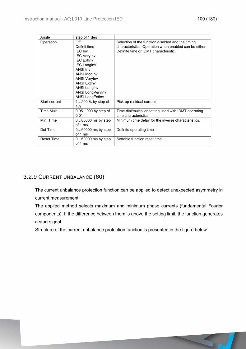
Instruction manual –AQ L310 Line Protection IED 100 (180)
Angle step of 1 deg
Operation Off
Definit time
IEC Inv
IEC VeryInv
IEC ExtInv
IEC LongInv
ANSI Inv
ANSI ModInv
ANSI VeryInv
ANSI ExtInv
ANSI LongInv
ANSI LongVeryInv
ANSI LongExtInv
Selection of the function disabled and the timing
characteristics. Operation when enabled can be either
Definite time or IDMT characteristic.
Start current 1…200 % by step of
1%
Pick-up residual current
Time Mult 0.05…999 by step of
0.01
Time dial/multiplier setting used with IDMT operating
time characteristics.
Min. Time 0…60000 ms by step
of 1 ms
Minimum time delay for the inverse characteristics.
Def Time 0…60000 ms by step
of 1 ms
Definite operating time
Reset Time 0…60000 ms by step
of 1 ms
Settable function reset time
3.2.9 CURRENT UNBALANCE (60)
The current unbalance protection function can be applied to detect unexpected asymmetry in
current measurement.
The applied method selects maximum and minimum phase currents (fundamental Fourier
components). If the difference between them is above the setting limit, the function generates
a start signal.
Structure of the current unbalance protection function is presented in the figure below
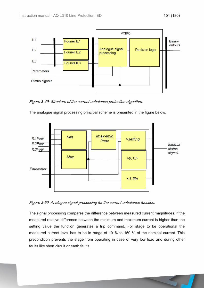
Instruction manual –AQ L310 Line Protection IED 101 (180)
Figure 3-49: Structure of the current unbalance protection algorithm.
The analogue signal processing principal scheme is presented in the figure below.
Figure 3-50: Analogue signal processing for the current unbalance function.
The signal processing compares the difference between measured current magnitudes. If the
measured relative difference between the minimum and maximum current is higher than the
setting value the function generates a trip command. For stage to be operational the
measured current level has to be in range of 10 % to 150 % of the nominal current. This
precondition prevents the stage from operating in case of very low load and during other
faults like short circuit or earth faults.
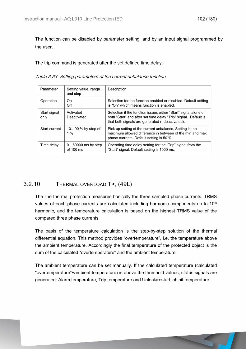
Instruction manual –AQ L310 Line Protection IED 102 (180)
The function can be disabled by parameter setting, and by an input signal programmed by
the user.
The trip command is generated after the set defined time delay.
Table 3-33: Setting parameters of the current unbalance function
Parameter Setting value, range
and step
Description
Operation On
Off
Selection for the function enabled or disabled. Default setting
is “On” which means function is enabled.
Start signal
only
Activated
Deactivated
Selection if the function issues either “Start” signal alone or
both “Start” and after set time delay “Trip” signal. Default is
that both signals are generated (=deactivated).
Start current 10…90 % by step of
1 %
Pick up setting of the current unbalance. Setting is the
maximum allowed difference in between of the min and max
phase currents. Default setting is 50 %.
Time delay 0…60000 ms by step
of 100 ms
Operating time delay setting for the “Trip” signal from the
“Start” signal. Default setting is 1000 ms.
3.2.10 THERMAL OVERLOAD T>, (49L)
The line thermal protection measures basically the three sampled phase currents. TRMS
values of each phase currents are calculated including harmonic components up to 10th
harmonic, and the temperature calculation is based on the highest TRMS value of the
compared three phase currents.
The basis of the temperature calculation is the step-by-step solution of the thermal
differential equation. This method provides “overtemperature”, i.e. the temperature above
the ambient temperature. Accordingly the final temperature of the protected object is the
sum of the calculated “overtemperature” and the ambient temperature.
The ambient temperature can be set manually. If the calculated temperature (calculated
“overtemperature”+ambient temperature) is above the threshold values, status signals are
generated: Alarm temperature, Trip temperature and Unlock/restart inhibit temperature.
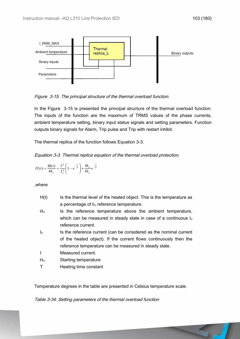
Instruction manual –AQ L310 Line Protection IED 103 (180)
Figure 3-15. The principal structure of the thermal overload function.
In the Figure 3-15 is presented the principal structure of the thermal overload function.
The inputs of the function are the maximum of TRMS values of the phase currents,
ambient temperature setting, binary input status signals and setting parameters. Function
outputs binary signals for Alarm, Trip pulse and Trip with restart inhibit.
The thermal replica of the function follows Equation 3-3.
Equation 3-3. Thermal replica equation of the thermal overload protection.
,where
H(t) Is the thermal level of the heated object. This is the temperature as
a percentage of n reference temperature.
n Is the reference temperature above the ambient temperature,
which can be measured in steady state in case of a continuous In
reference current.
In Is the reference current (can be considered as the nominal current
of the heated object). If the current flows continuously then the
reference temperature can be measured in steady state.
I Measured current.
o Starting temperature
T Heating time constant
Temperature degrees in the table are presented in Celsius temperature scale.
Table 3-34: Setting parameters of the thermal overload function
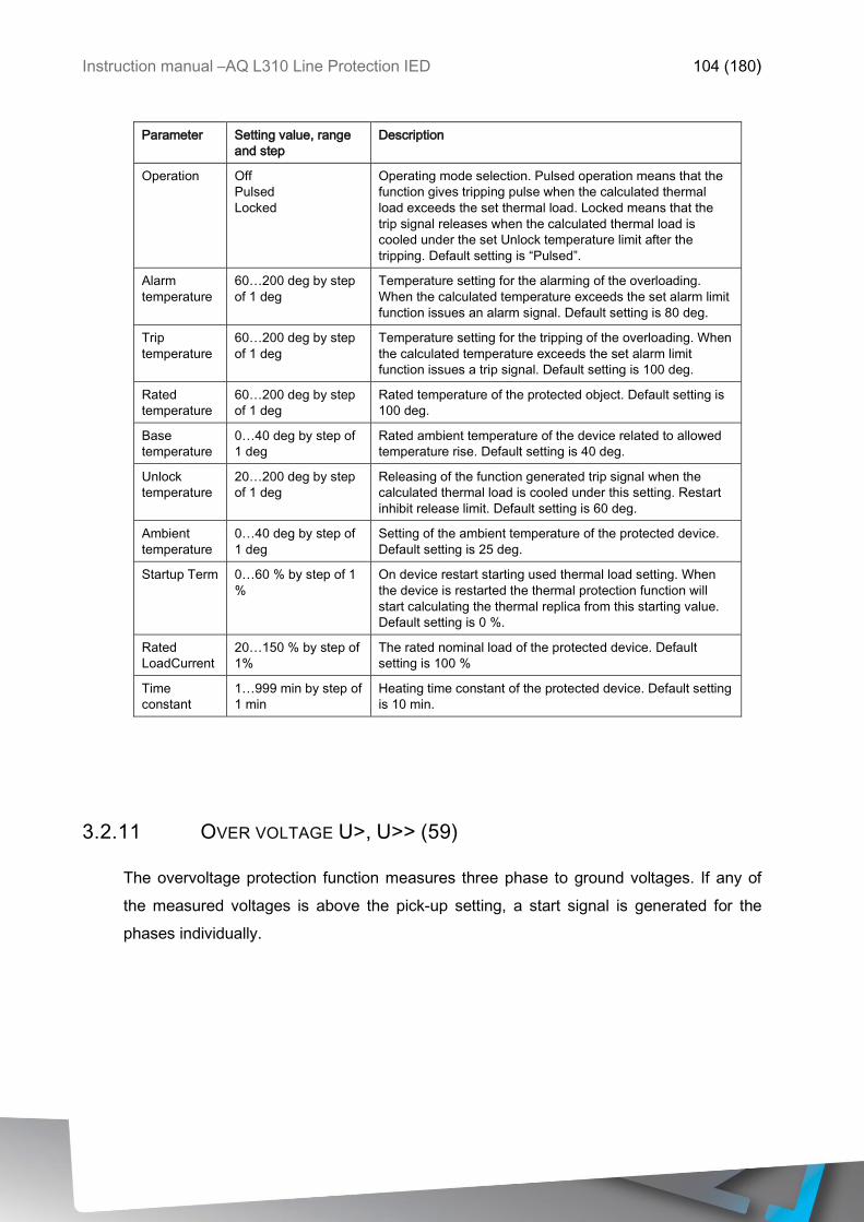
Instruction manual –AQ L310 Line Protection IED 104 (180)
Parameter Setting value, range
and step
Description
Operation Off
Pulsed
Locked
Operating mode selection. Pulsed operation means that the
function gives tripping pulse when the calculated thermal
load exceeds the set thermal load. Locked means that the
trip signal releases when the calculated thermal load is
cooled under the set Unlock temperature limit after the
tripping. Default setting is “Pulsed”.
Alarm
temperature
60…200 deg by step
of 1 deg
Temperature setting for the alarming of the overloading.
When the calculated temperature exceeds the set alarm limit
function issues an alarm signal. Default setting is 80 deg.
Trip
temperature
60…200 deg by step
of 1 deg
Temperature setting for the tripping of the overloading. When
the calculated temperature exceeds the set alarm limit
function issues a trip signal. Default setting is 100 deg.
Rated
temperature
60…200 deg by step
of 1 deg
Rated temperature of the protected object. Default setting is
100 deg.
Base
temperature
0…40 deg by step of
1 deg
Rated ambient temperature of the device related to allowed
temperature rise. Default setting is 40 deg.
Unlock
temperature
20…200 deg by step
of 1 deg
Releasing of the function generated trip signal when the
calculated thermal load is cooled under this setting. Restart
inhibit release limit. Default setting is 60 deg.
Ambient
temperature
0…40 deg by step of
1 deg
Setting of the ambient temperature of the protected device.
Default setting is 25 deg.
Startup Term 0…60 % by step of 1
%
On device restart starting used thermal load setting. When
the device is restarted the thermal protection function will
start calculating the thermal replica from this starting value.
Default setting is 0 %.
Rated
LoadCurrent
20…150 % by step of
1%
The rated nominal load of the protected device. Default
setting is 100 %
Time
constant
1…999 min by step of
1 min
Heating time constant of the protected device. Default setting
is 10 min.
3.2.11 OVER VOLTAGE U>, U>> (59)
The overvoltage protection function measures three phase to ground voltages. If any of
the measured voltages is above the pick-up setting, a start signal is generated for the
phases individually.
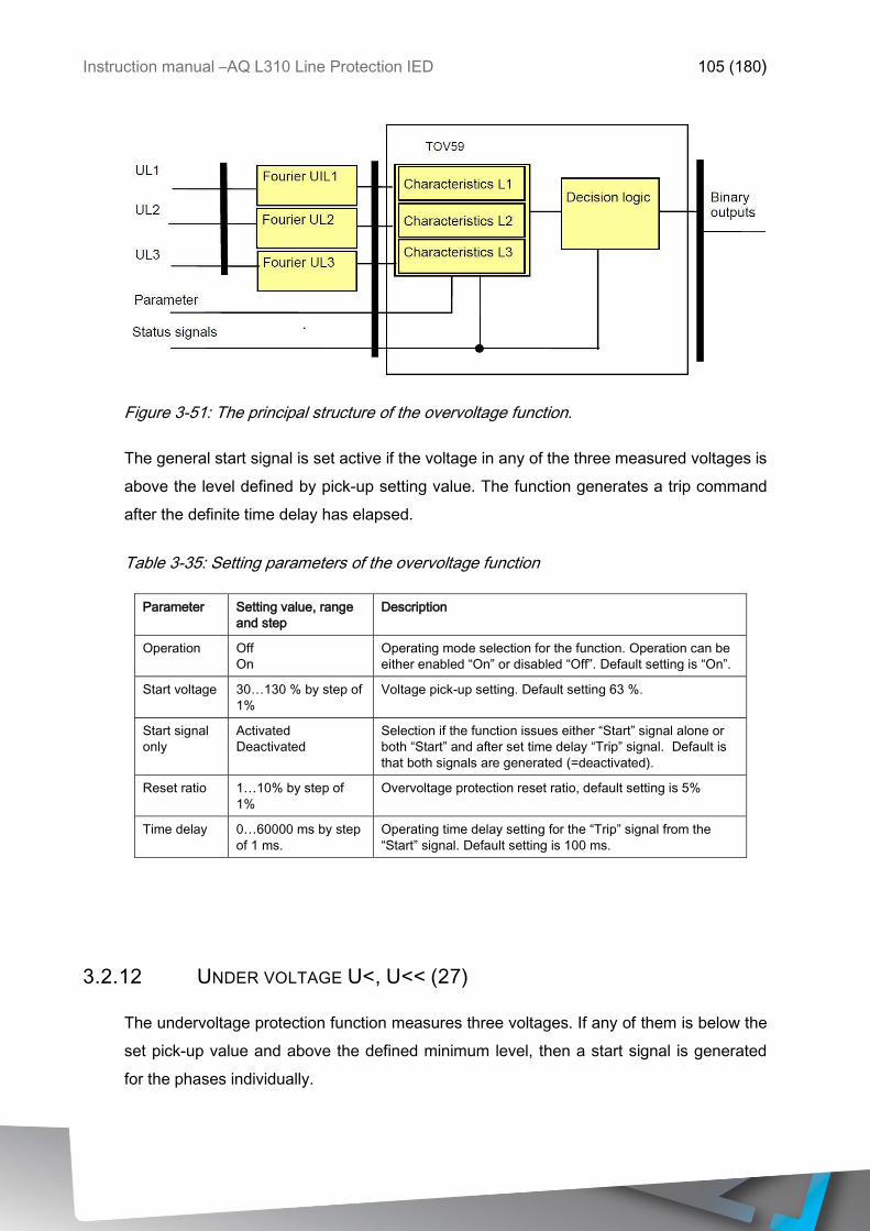
Instruction manual –AQ L310 Line Protection IED 105 (180)
Figure 3-51: The principal structure of the overvoltage function.
The general start signal is set active if the voltage in any of the three measured voltages is
above the level defined by pick-up setting value. The function generates a trip command
after the definite time delay has elapsed.
Table 3-35: Setting parameters of the overvoltage function
Parameter Setting value, range
and step
Description
Operation Off
On
Operating mode selection for the function. Operation can be
either enabled “On” or disabled “Off”. Default setting is “On”.
Start voltage 30…130 % by step of
1%
Voltage pick-up setting. Default setting 63 %.
Start signal
only
Activated
Deactivated
Selection if the function issues either “Start” signal alone or
both “Start” and after set time delay “Trip” signal. Default is
that both signals are generated (=deactivated).
Reset ratio 1…10% by step of
1%
Overvoltage protection reset ratio, default setting is 5%
Time delay 0…60000 ms by step
of 1 ms.
Operating time delay setting for the “Trip” signal from the
“Start” signal. Default setting is 100 ms.
3.2.12 UNDER VOLTAGE U<, U<< (27)
The undervoltage protection function measures three voltages. If any of them is below the
set pick-up value and above the defined minimum level, then a start signal is generated
for the phases individually.
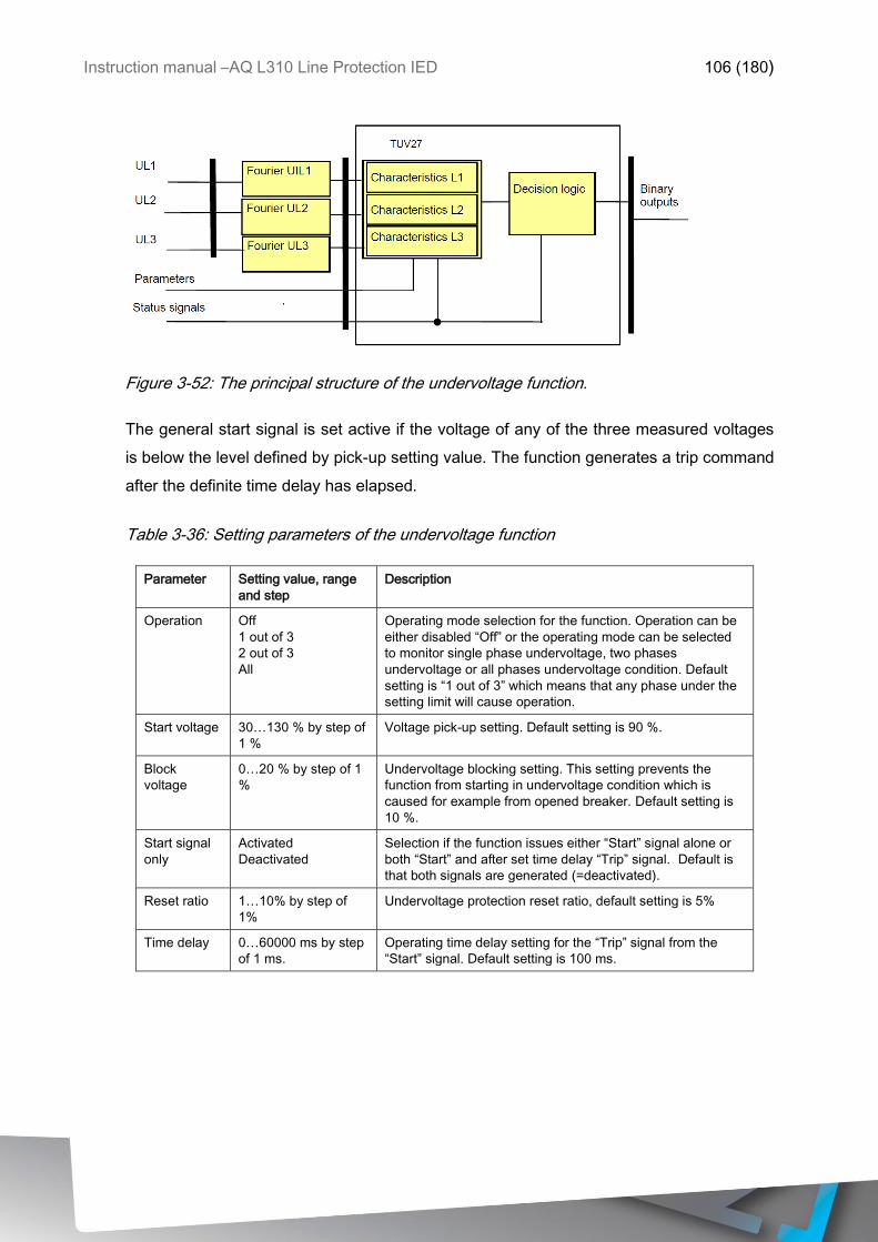
Instruction manual –AQ L310 Line Protection IED 106 (180)
Figure 3-52: The principal structure of the undervoltage function.
The general start signal is set active if the voltage of any of the three measured voltages
is below the level defined by pick-up setting value. The function generates a trip command
after the definite time delay has elapsed.
Table 3-36: Setting parameters of the undervoltage function
Parameter Setting value, range
and step
Description
Operation Off
1 out of 3
2 out of 3
All
Operating mode selection for the function. Operation can be
either disabled “Off” or the operating mode can be selected
to monitor single phase undervoltage, two phases
undervoltage or all phases undervoltage condition. Default
setting is “1 out of 3” which means that any phase under the
setting limit will cause operation.
Start voltage 30…130 % by step of
1 %
Voltage pick-up setting. Default setting is 90 %.
Block
voltage
0…20 % by step of 1
%
Undervoltage blocking setting. This setting prevents the
function from starting in undervoltage condition which is
caused for example from opened breaker. Default setting is
10 %.
Start signal
only
Activated
Deactivated
Selection if the function issues either “Start” signal alone or
both “Start” and after set time delay “Trip” signal. Default is
that both signals are generated (=deactivated).
Reset ratio 1…10% by step of
1%
Undervoltage protection reset ratio, default setting is 5%
Time delay 0…60000 ms by step
of 1 ms.
Operating time delay setting for the “Trip” signal from the
“Start” signal. Default setting is 100 ms.
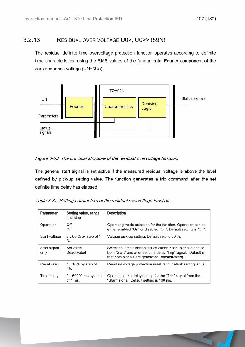
Instruction manual –AQ L310 Line Protection IED 107 (180)
3.2.13 RESIDUAL OVER VOLTAGE U0>, U0>> (59N)
The residual definite time overvoltage protection function operates according to definite
time characteristics, using the RMS values of the fundamental Fourier component of the
zero sequence voltage (UN=3Uo).
Figure 3-53: The principal structure of the residual overvoltage function.
The general start signal is set active if the measured residual voltage is above the level
defined by pick-up setting value. The function generates a trip command after the set
definite time delay has elapsed.
Table 3-37: Setting parameters of the residual overvoltage function
Parameter Setting value, range
and step
Description
Operation Off
On
Operating mode selection for the function. Operation can be
either enabled “On” or disabled “Off”. Default setting is “On”.
Start voltage 2…60 % by step of 1
%
Voltage pick-up setting. Default setting 30 %.
Start signal
only
Activated
Deactivated
Selection if the function issues either “Start” signal alone or
both “Start” and after set time delay “Trip” signal. Default is
that both signals are generated (=deactivated).
Reset ratio 1…10% by step of
1%
Residual voltage protection reset ratio, default setting is 5%
Time delay 0…60000 ms by step
of 1 ms.
Operating time delay setting for the “Trip” signal from the
“Start” signal. Default setting is 100 ms.
Instruction manual –AQ L310 Line Protection IED 108 (180)
3.2.14 OVER FREQUENCY F>, F>>, (81O)
The deviation of the frequency from the rated system frequency indicates unbalance
between the generated power and the load demand. If the available generation is large
compared to the consumption by the load connected to the power system, then the system
frequency is above the rated value.
The over-frequency protection function is usually applied to decrease generation to control
the system frequency. Another possible application is the detection of unintended island
operation of distributed generation and some consumers. In the island, there is low
probability that the power generated is the same as consumption; accordingly, the detection
of high frequency can be an indication of island operation. Accurate frequency measurement
is also the criterion for the synchro-check and synchro-switch functions.
The frequency measurement is based on channel No. 1 (line voltage) or channel No. 4
(busbar voltage) of the voltage input module. In some applications, the frequency is
measured based on the weighted sum of the phase voltages. The accurate frequency
measurement is performed by measuring the time period between two rising edges at zero
crossing of a voltage signal.
For the confirmation of the measured frequency, at least four subsequent identical
measurements are needed. Similarly, four invalid measurements are needed to reset the
measured frequency to zero. The basic criterion is that the evaluated voltage should be
above 30% of the rated voltage value. The over-frequency protection function generates a
start signal if at least five measured frequency values are above the preset level.
Instruction manual –AQ L310 Line Protection IED 109 (180)
Table 3-38 Setting parameters of the over frequency protection function
Parameter Setting value, range
and step
Description
Operation Off
On
Operating mode selection for the function. Operation can be
either disabled “Off” or enabled “On”. Default setting is
enabled.
Start signal
only
Activated
Deactivated
Selection if the function issues either “Start” signal alone or
both “Start” and after set time delay “Trip” signal. Default is
that both signals are generated (=deactivated).
Start
frequency
40.00…60.00 Hz by
step of 0.01 Hz
Pick up setting of the function. When the measured
frequency value exceeds the setting value function initiates
“Start” signal. Default setting is 51 Hz
Time delay 100…60000 ms by
step of 1 ms.
Operating time delay setting for the “Trip” signal from the
“Start” signal. Default setting is 200 ms.
3.2.15 UNDER FREQUENCY F<, F<<, (81L)
The deviation of the frequency from the rated system frequency indicates unbalance
between the generated power and the load demand. If the available generation is small
compared to the consumption by the load connected to the power system, then the system
frequency is below the rated value.
The under-frequency protection function is usually applied to increase generation or for load
shedding to control the system frequency. Another possible application is the detection of
unintended island operation of distributed generation and some consumers. In the island,
there is low probability that the power generated is the same as consumption; accordingly,
the detection of low frequency can be an indication of island operation. Accurate frequency
measurement is also the criterion for the synchro-check and synchro-switch functions.
The frequency measurement is based on channel No. 1 (line voltage) or channel No. 4
(busbar voltage) of the voltage input module. In some applications, the frequency is
measured based on the weighted sum of the phase voltages. The accurate frequency
measurement is performed by measuring the time period between two rising edges at zero
crossing of a voltage signal.
For the confirmation of the measured frequency, at least four subsequent identical
measurements are needed. Similarly, four invalid measurements are needed to reset the
measured frequency to zero. The basic criterion is that the evaluated voltage should be
Instruction manual –AQ L310 Line Protection IED 110 (180)
above 30% of the rated voltage value. The under-frequency protection function generates
a start signal if at least five measured frequency values are below the setting value.
Table 3-39: Setting parameters of the under-frequency function
Parameter Setting value, range
and step
Description
Operation Off
On
Operating mode selection for the function. Operation can be
either disabled “Off” or enabled “On”. Default setting is
enabled.
Start signal
only
Activated
Deactivated
Selection if the function issues either “Start” signal alone or
both “Start” and after set time delay “Trip” signal. Default is
that both signals are generated (=deactivated).
Start
frequency
40.00…60.00 Hz by
step of 0.01 Hz
Pick up setting of the function. When the measured
frequency value exceeds the setting value function initiates
“Start” signal. Default setting is 49 Hz
Time delay 100…60000 ms by
step of 1 ms.
Operating time delay setting for the “Trip” signal from the
“Start” signal. Default setting is 200 ms.
3.2.16 RATE OF CHANGE OF FREQUENCY DF/DT>, DF/DT>> (81R)
The deviation of the frequency from the rated system frequency indicates unbalance
between the generated power and the load demand. If the available generation is small
compared to the consumption by the load connected to the power system, then the system
frequency is below the rated value. If the unbalance is large, then the frequency changes
rapidly. The rate of change of frequency protection function is usually applied to reset the
balance between generation and consumption to control the system frequency. Another
possible application is the detection of unintended island operation of distributed generation
and some consumers. In the island, there is low probability that the power generated is the
same as consumption; accordingly, the detection of a high rate of change of frequency can
be an indication of island operation. Accurate frequency measurement is also the criterion for
the synchro-switch function.
The source for the rate of change of frequency calculation is an accurate frequency
measurement. The frequency measurement is based on channel No. 1 (line voltage) or
channel No. 4 (busbar voltage) of the voltage input module. In some applications, the
frequency is measured based on the weighted sum of the phase voltages. The accurate
frequency measurement is performed by measuring the time period between two rising
edges at zero crossing of a voltage signal.
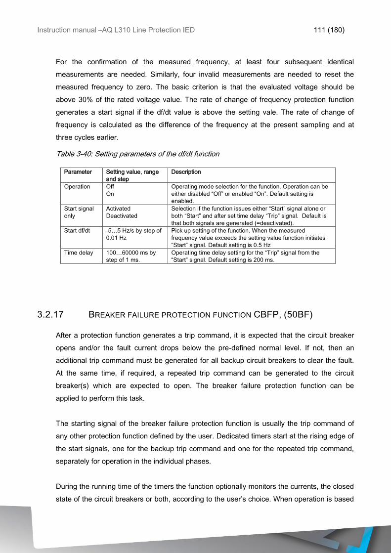
Instruction manual –AQ L310 Line Protection IED 111 (180)
For the confirmation of the measured frequency, at least four subsequent identical
measurements are needed. Similarly, four invalid measurements are needed to reset the
measured frequency to zero. The basic criterion is that the evaluated voltage should be
above 30% of the rated voltage value. The rate of change of frequency protection function
generates a start signal if the df/dt value is above the setting vale. The rate of change of
frequency is calculated as the difference of the frequency at the present sampling and at
three cycles earlier.
Table 3-40: Setting parameters of the df/dt function
Parameter Setting value, range
and step
Description
Operation Off
On
Operating mode selection for the function. Operation can be
either disabled “Off” or enabled “On”. Default setting is
enabled.
Start signal
only
Activated
Deactivated
Selection if the function issues either “Start” signal alone or
both “Start” and after set time delay “Trip” signal. Default is
that both signals are generated (=deactivated).
Start df/dt -5…5 Hz/s by step of
0.01 Hz
Pick up setting of the function. When the measured
frequency value exceeds the setting value function initiates
“Start” signal. Default setting is 0.5 Hz
Time delay 100…60000 ms by
step of 1 ms.
Operating time delay setting for the “Trip” signal from the
“Start” signal. Default setting is 200 ms.
3.2.17 BREAKER FAILURE PROTECTION FUNCTION CBFP, (50BF)
After a protection function generates a trip command, it is expected that the circuit breaker
opens and/or the fault current drops below the pre-defined normal level. If not, then an
additional trip command must be generated for all backup circuit breakers to clear the fault.
At the same time, if required, a repeated trip command can be generated to the circuit
breaker(s) which are expected to open. The breaker failure protection function can be
applied to perform this task.
The starting signal of the breaker failure protection function is usually the trip command of
any other protection function defined by the user. Dedicated timers start at the rising edge of
the start signals, one for the backup trip command and one for the repeated trip command,
separately for operation in the individual phases.
During the running time of the timers the function optionally monitors the currents, the closed
state of the circuit breakers or both, according to the user’s choice. When operation is based
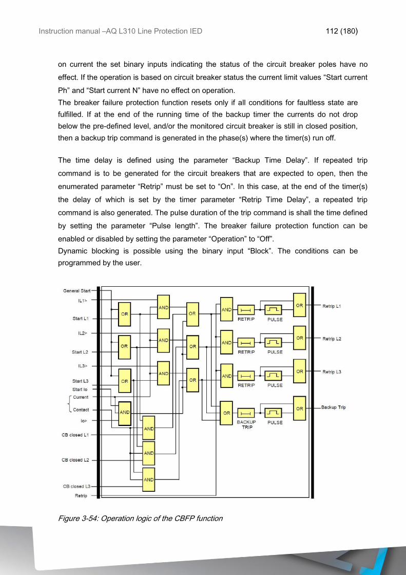
Instruction manual –AQ L310 Line Protection IED 112 (180)
on current the set binary inputs indicating the status of the circuit breaker poles have no
effect. If the operation is based on circuit breaker status the current limit values “Start current
Ph” and “Start current N” have no effect on operation.
The breaker failure protection function resets only if all conditions for faultless state are
fulfilled. If at the end of the running time of the backup timer the currents do not drop
below the pre-defined level, and/or the monitored circuit breaker is still in closed position,
then a backup trip command is generated in the phase(s) where the timer(s) run off.
The time delay is defined using the parameter “Backup Time Delay”. If repeated trip
command is to be generated for the circuit breakers that are expected to open, then the
enumerated parameter “Retrip” must be set to “On”. In this case, at the end of the timer(s)
the delay of which is set by the timer parameter “Retrip Time Delay”, a repeated trip
command is also generated. The pulse duration of the trip command is shall the time defined
by setting the parameter “Pulse length”. The breaker failure protection function can be
enabled or disabled by setting the parameter “Operation” to “Off”.
Dynamic blocking is possible using the binary input “Block”. The conditions can be
programmed by the user.
Figure 3-54: Operation logic of the CBFP function
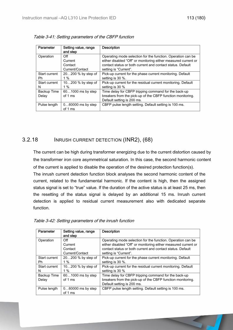
Instruction manual –AQ L310 Line Protection IED 113 (180)
Table 3-41: Setting parameters of the CBFP function
Parameter Setting value, range
and step
Description
Operation Off
Current
Contact
Current/Contact
Operating mode selection for the function. Operation can be
either disabled “Off” or monitoring either measured current or
contact status or both current and contact status. Default
setting is “Current”.
Start current
Ph
20…200 % by step of
1 %
Pick-up current for the phase current monitoring. Default
setting is 30 %.
Start current
N
10…200 % by step of
1 %
Pick-up current for the residual current monitoring. Default
setting is 30 %
Backup Time
Delay
60…1000 ms by step
of 1 ms
Time delay for CBFP tripping command for the back-up
breakers from the pick-up of the CBFP function monitoring.
Default setting is 200 ms.
Pulse length 0…60000 ms by step
of 1 ms
CBFP pulse length setting. Default setting is 100 ms.
3.2.18 INRUSH CURRENT DETECTION (INR2), (68)
The current can be high during transformer energizing due to the current distortion caused by
the transformer iron core asymmetrical saturation. In this case, the second harmonic content
of the current is applied to disable the operation of the desired protection function(s).
The inrush current detection function block analyses the second harmonic content of the
current, related to the fundamental harmonic. If the content is high, then the assigned
status signal is set to “true” value. If the duration of the active status is at least 25 ms, then
the resetting of the status signal is delayed by an additional 15 ms. Inrush current
detection is applied to residual current measurement also with dedicated separate
function.
Table 3-42: Setting parameters of the inrush function
Parameter Setting value, range
and step
Description
Operation Off
Current
Contact
Current/Contact
Operating mode selection for the function. Operation can be
either disabled “Off” or monitoring either measured current or
contact status or both current and contact status. Default
setting is “Current”.
Start current
Ph
20…200 % by step of
1 %
Pick-up current for the phase current monitoring. Default
setting is 30 %.
Start current
N
10…200 % by step of
1 %
Pick-up current for the residual current monitoring. Default
setting is 30 %
Backup Time
Delay
60…1000 ms by step
of 1 ms
Time delay for CBFP tripping command for the back-up
breakers from the pick-up of the CBFP function monitoring.
Default setting is 200 ms.
Pulse length 0…60000 ms by step
of 1 ms
CBFP pulse length setting. Default setting is 100 ms.
Instruction manual –AQ L310 Line Protection IED 114 (180)
3.3 CONTROL AND MONITORING FUNCTIONS
3.3.1 COMMON-FUNCTION
The AQ300 series devices – independently of the configured protection functions – have
some common functionality. The Common function block enables certain kind of extension
this common functionality:
1. The WARNING signal of the device
The AQ300 series devices have several LED-s on the front panel. The upper left LED
indicates the state of the device:
Green means normal operation
Yellow means WARNING state
The device is booting while the protection functions are operable
No time synchron signal is received
There are some setting errors such as the rated frequency setting does
not correspond to the measured frequency, mismatch in vector group
setting in case of transformer with three voltage levels, etc.
Wrong phase-voltage v.s. line-to-line voltage assignment
No frequency source is assigned for frequency related functions
The device is switched off from normal mode to Blocked or Test or Off
mode, • the device is in simulation mode
There is some mismatch in setting the rated values of the analog inputs.
Red means ERROR state. (This state is indicated also by the dedicated binary
output of the power supply module.)
The list of the sources of the WARNING state can be extended using the Common function
block. This additional signal is programmed by the user with the help of the graphic logic
editor.
2. The latched LED signals
The latched LED signals can be reset:
By the dedicated push button below the LED-s on the front panel of the device
Using the computer connection and generating a LED reset command
Via SCADA system, if it is configured

Instruction manual –AQ L310 Line Protection IED 115 (180)
The list of the sources of the LED reset commands can be extended using
the Common function block. This additional signal is programmed by the
user with the help of the graphic logic editor.
The list of the sources of the LED reset commands can be extended using the Common
function block. This additional signal is programmed by the user with the help of the graphic
logic editor.
3. The Local/Remote state for generating command to or via the device
The Local/Remote state of the device can be toggled:
From the local front-panel touch-screen of the device
The Local/Remote selection can be extended using the Common function block. There is
possibility to apply up to 4 groups, the Local/Remote states of which can be set separately.
These additional signals are programmed by the user with the help of the graphic logic editor
4. AckButton output of the common function block generates a signal whenever the “X”
button in the front panel of the relay has been pressed.
5. FixFalse/True can be used to write continuous 0 or 1 into an input of a function block or a
logic gate.
The Common function block has binary input signals. The conditions are defined by the user
applying the graphic logic editor.
Figure 3-55: The function block of the Common function block
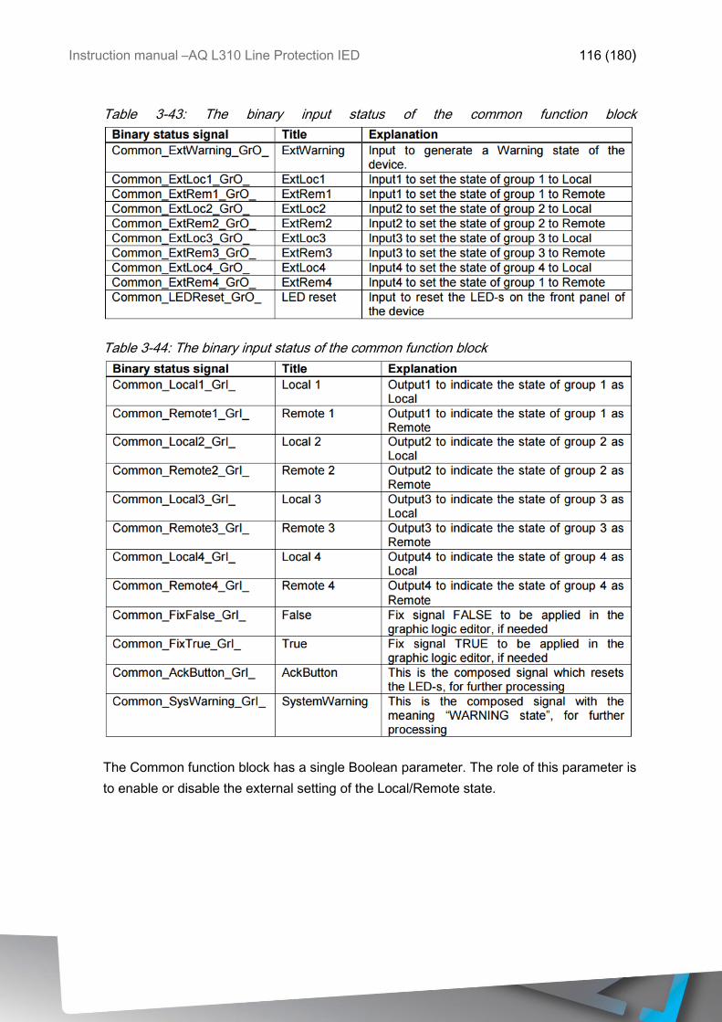
Instruction manual –AQ L310 Line Protection IED 116 (180)
Table 3-43: The binary input status of the common function block
Table 3-44: The binary input status of the common function block
The Common function block has a single Boolean parameter. The role of this parameter is
to enable or disable the external setting of the Local/Remote state.
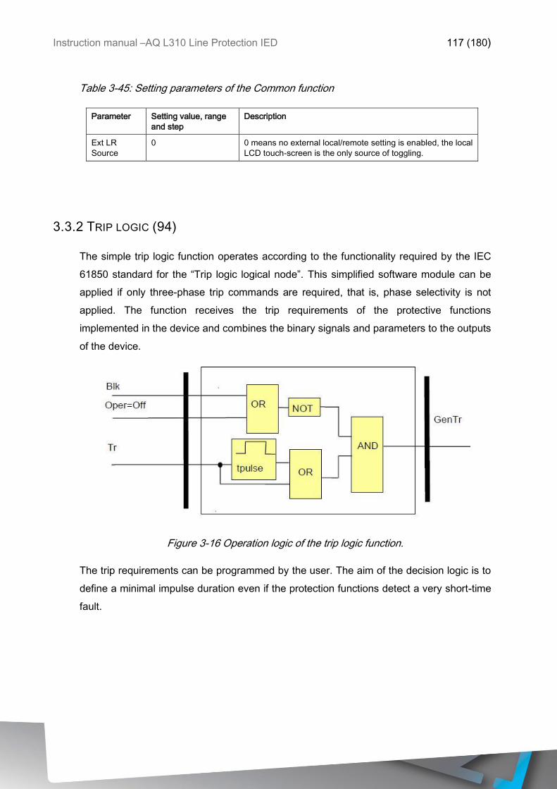
Instruction manual –AQ L310 Line Protection IED 117 (180)
Table 3-45: Setting parameters of the Common function
Parameter Setting value, range
and step
Description
Ext LR
Source
0 0 means no external local/remote setting is enabled, the local
LCD touch-screen is the only source of toggling.
3.3.2 TRIP LOGIC (94)
The simple trip logic function operates according to the functionality required by the IEC
61850 standard for the “Trip logic logical node”. This simplified software module can be
applied if only three-phase trip commands are required, that is, phase selectivity is not
applied. The function receives the trip requirements of the protective functions
implemented in the device and combines the binary signals and parameters to the outputs
of the device.
Figure 3-16 Operation logic of the trip logic function.
The trip requirements can be programmed by the user. The aim of the decision logic is to
define a minimal impulse duration even if the protection functions detect a very short-time
fault.
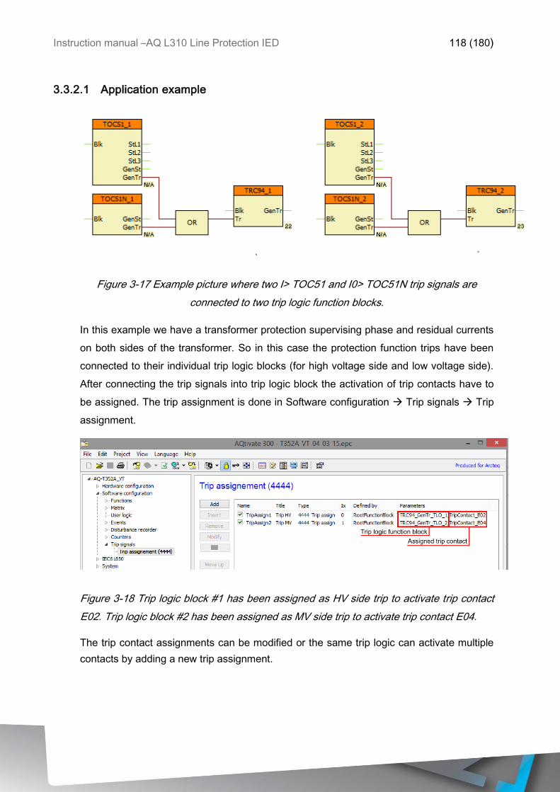
Instruction manual –AQ L310 Line Protection IED 118 (180)
3.3.2.1 Application example
Figure 3-17 Example picture where two I> TOC51 and I0> TOC51N trip signals are
connected to two trip logic function blocks.
In this example we have a transformer protection supervising phase and residual currents
on both sides of the transformer. So in this case the protection function trips have been
connected to their individual trip logic blocks (for high voltage side and low voltage side).
After connecting the trip signals into trip logic block the activation of trip contacts have to
be assigned. The trip assignment is done in Software configuration Trip signals Trip
assignment.
Figure 3-18 Trip logic block #1 has been assigned as HV side trip to activate trip contact
E02. Trip logic block #2 has been assigned as MV side trip to activate trip contact E04.
The trip contact assignments can be modified or the same trip logic can activate multiple
contacts by adding a new trip assignment.
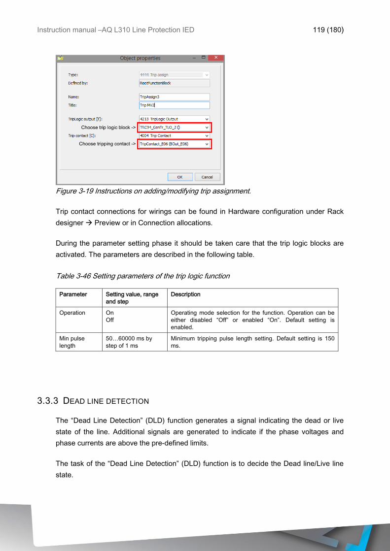
Instruction manual –AQ L310 Line Protection IED 119 (180)
Figure 3-19 Instructions on adding/modifying trip assignment.
Trip contact connections for wirings can be found in Hardware configuration under Rack
designer Preview or in Connection allocations.
During the parameter setting phase it should be taken care that the trip logic blocks are
activated. The parameters are described in the following table.
Table 3-46 Setting parameters of the trip logic function
Parameter Setting value, range
and step
Description
Operation On
Off
Operating mode selection for the function. Operation can be
either disabled “Off” or enabled “On”. Default setting is
enabled.
Min pulse
length
50…60000 ms by
step of 1 ms
Minimum tripping pulse length setting. Default setting is 150
ms.
3.3.3 DEAD LINE DETECTION
The “Dead Line Detection” (DLD) function generates a signal indicating the dead or live
state of the line. Additional signals are generated to indicate if the phase voltages and
phase currents are above the pre-defined limits.
The task of the “Dead Line Detection” (DLD) function is to decide the Dead line/Live line
state.
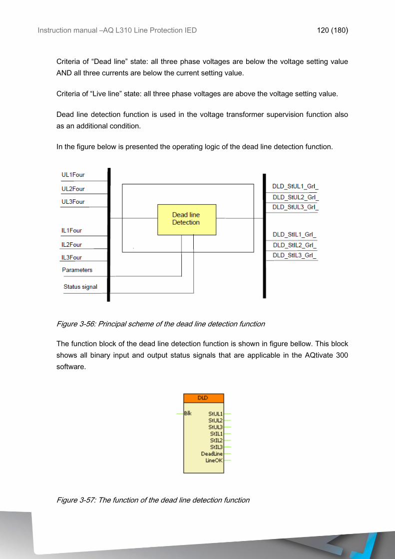
Instruction manual –AQ L310 Line Protection IED 120 (180)
Criteria of “Dead line” state: all three phase voltages are below the voltage setting value
AND all three currents are below the current setting value.
Criteria of “Live line” state: all three phase voltages are above the voltage setting value.
Dead line detection function is used in the voltage transformer supervision function also
as an additional condition.
In the figure below is presented the operating logic of the dead line detection function.
Figure 3-56: Principal scheme of the dead line detection function
The function block of the dead line detection function is shown in figure bellow. This block
shows all binary input and output status signals that are applicable in the AQtivate 300
software.
Figure 3-57: The function of the dead line detection function
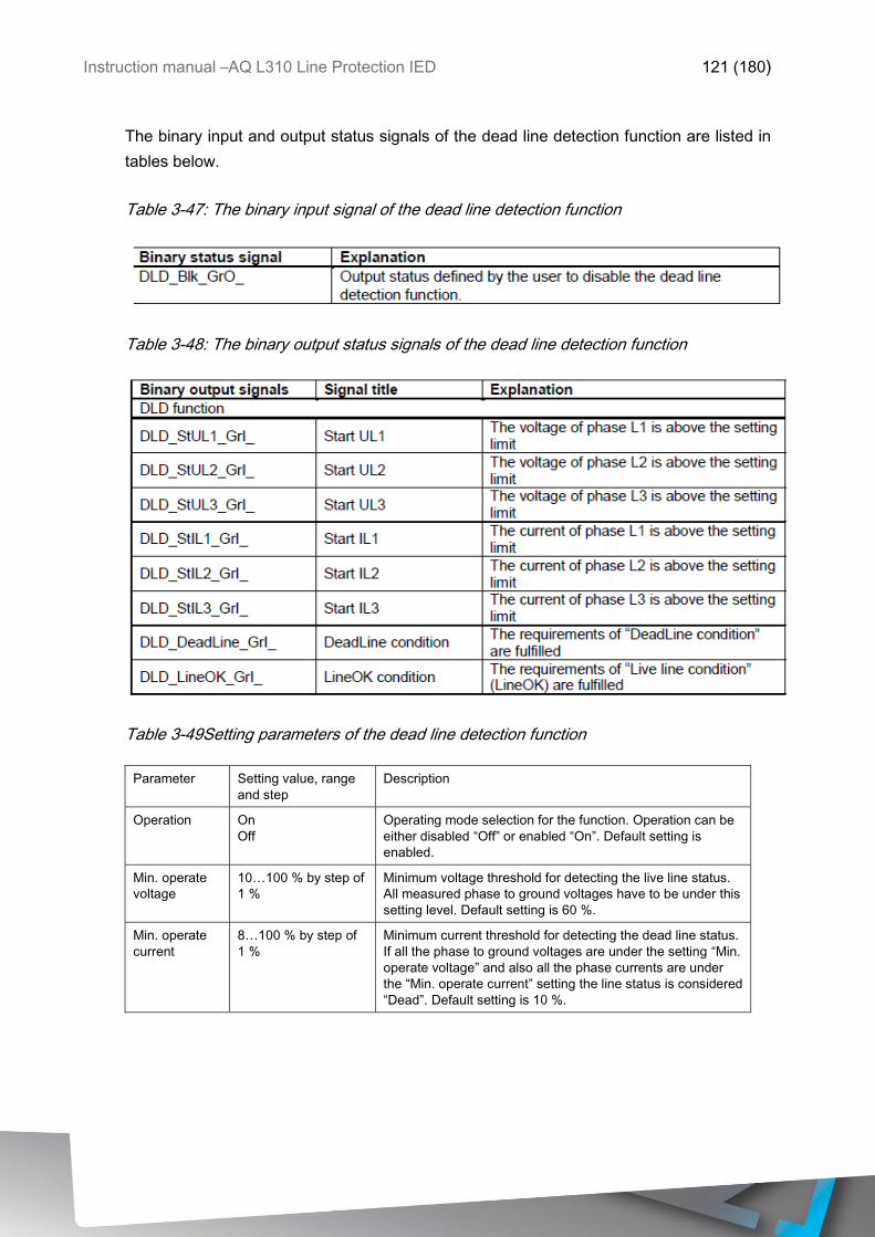
Instruction manual –AQ L310 Line Protection IED 121 (180)
The binary input and output status signals of the dead line detection function are listed in
tables below.
Table 3-47: The binary input signal of the dead line detection function
Table 3-48: The binary output status signals of the dead line detection function
Table 3-49Setting parameters of the dead line detection function
Parameter Setting value, range
and step
Description
Operation On
Off
Operating mode selection for the function. Operation can be
either disabled “Off” or enabled “On”. Default setting is
enabled.
Min. operate
voltage
10…100 % by step of
1 %
Minimum voltage threshold for detecting the live line status.
All measured phase to ground voltages have to be under this
setting level. Default setting is 60 %.
Min. operate
current
8…100 % by step of
1 %
Minimum current threshold for detecting the dead line status.
If all the phase to ground voltages are under the setting “Min.
operate voltage” and also all the phase currents are under
the “Min. operate current” setting the line status is considered
“Dead”. Default setting is 10 %.
Instruction manual –AQ L310 Line Protection IED 122 (180)
3.3.4 VOLTAGE TRANSFORMER SUPERVISION (VTS)
The voltage transformer supervision function generates a signal to indicate an error in the
voltage transformer secondary circuit. This signal can serve, for example, a warning,
indicating disturbances in the measurement, or it can disable the operation of the distance
protection function if appropriate measured voltage signals are not available for a distance
decision.
The voltage transformer supervision function is designed to detect faulty asymmetrical
states of the voltage transformer circuit caused, for example, by a broken conductor in the
secondary circuit. The voltage transformer supervision function can be used for either
tripping or alarming purposes.
The voltage transformer supervision function can be used in three different modes of
application:
Zero sequence detection (for typical applications in systems with grounded neutral): “VT
failure” signal is generated if the residual voltage (3Uo) is above the preset voltage value
AND the residual current (3Io) is below the preset current value
Negative sequence detection (for typical applications in systems with isolated or resonant
grounded (Petersen) neutral): “VT failure” signal is generated if the negative sequence
voltage component (U2) is above the preset voltage value AND the negative sequence
current component (I2) is below the preset current value.
Special application: “VT failure” signal is generated if the residual voltage (3Uo) is above
the preset voltage value AND the residual current (3Io) AND the negative sequence
current component (I2) are below the preset current values.
The voltage transformer supervision function can be triggered if “Live line” status is
detected for at least 200 ms. The purpose of this delay is to avoid mal-operation at line
energizing if the poles of the circuit breaker make contact with a time delay. The function
is set to be inactive if “Dead line” status is detected. If the conditions specified by the
selected mode of operation are fulfilled then the voltage transformer supervision function
is triggered and the operation signal is generated. When the conditions for operation are
no longer fulfilled, the resetting of the function depends on the mode of operation of the
primary circuit:
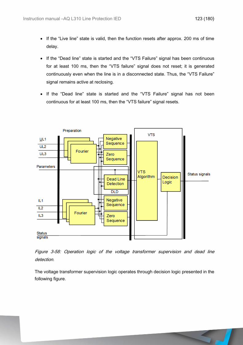
Instruction manual –AQ L310 Line Protection IED 123 (180)
If the “Live line” state is valid, then the function resets after approx. 200 ms of time
delay.
If the “Dead line” state is started and the “VTS Failure” signal has been continuous
for at least 100 ms, then the “VTS failure” signal does not reset; it is generated
continuously even when the line is in a disconnected state. Thus, the “VTS Failure”
signal remains active at reclosing.
If the “Dead line” state is started and the “VTS Failure” signal has not been
continuous for at least 100 ms, then the “VTS failure” signal resets.
Figure 3-58: Operation logic of the voltage transformer supervision and dead line
detection.
The voltage transformer supervision logic operates through decision logic presented in the
following figure.
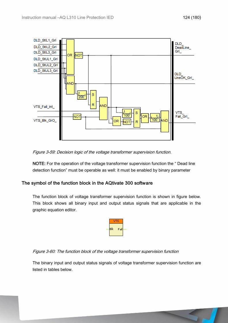
Instruction manual –AQ L310 Line Protection IED 124 (180)
Figure 3-59: Decision logic of the voltage transformer supervision function.
NOTE: For the operation of the voltage transformer supervision function the “ Dead line
detection function” must be operable as well: it must be enabled by binary parameter
The symbol of the function block in the AQtivate 300 software
The function block of voltage transformer supervision function is shown in figure below.
This block shows all binary input and output status signals that are applicable in the
graphic equation editor.
Figure 3-60: The function block of the voltage transformer supervision function
The binary input and output status signals of voltage transformer supervision function are
listed in tables below.
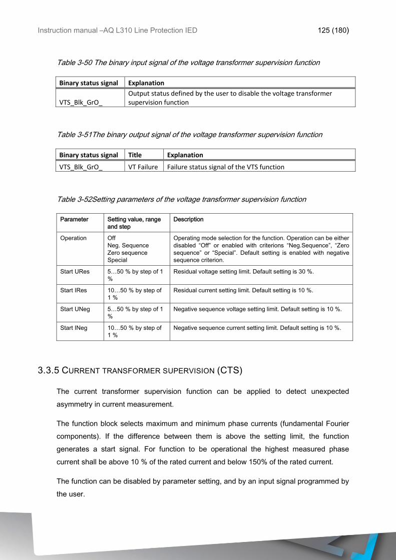
Instruction manual –AQ L310 Line Protection IED 125 (180)
Table 3-50 The binary input signal of the voltage transformer supervision function
Binary status signal Explanation
VTS_Blk_GrO_ Output status defined by the user to disable the voltage transformer supervision function
Table 3-51The binary output signal of the voltage transformer supervision function
Binary status signal Title Explanation
VTS_Blk_GrO_ VT Failure Failure status signal of the VTS function
Table 3-52Setting parameters of the voltage transformer supervision function
Parameter Setting value, range
and step
Description
Operation Off
Neg. Sequence
Zero sequence
Special
Operating mode selection for the function. Operation can be either
disabled “Off” or enabled with criterions “Neg.Sequence”, “Zero
sequence” or “Special”. Default setting is enabled with negative
sequence criterion.
Start URes 5…50 % by step of 1
%
Residual voltage setting limit. Default setting is 30 %.
Start IRes 10…50 % by step of
1 %
Residual current setting limit. Default setting is 10 %.
Start UNeg 5…50 % by step of 1
%
Negative sequence voltage setting limit. Default setting is 10 %.
Start INeg 10…50 % by step of
1 %
Negative sequence current setting limit. Default setting is 10 %.
3.3.5 CURRENT TRANSFORMER SUPERVISION (CTS)
The current transformer supervision function can be applied to detect unexpected
asymmetry in current measurement.
The function block selects maximum and minimum phase currents (fundamental Fourier
components). If the difference between them is above the setting limit, the function
generates a start signal. For function to be operational the highest measured phase
current shall be above 10 % of the rated current and below 150% of the rated current.
The function can be disabled by parameter setting, and by an input signal programmed by
the user.
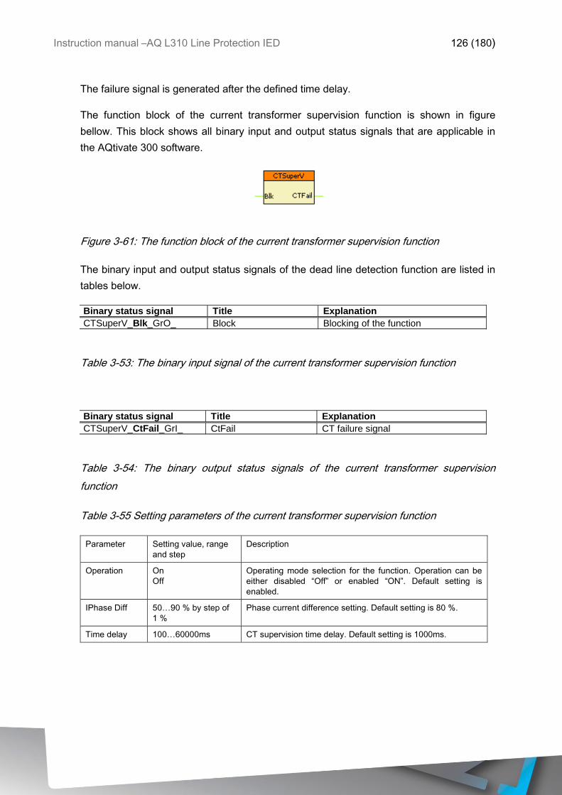
Instruction manual –AQ L310 Line Protection IED 126 (180)
The failure signal is generated after the defined time delay.
The function block of the current transformer supervision function is shown in figure
bellow. This block shows all binary input and output status signals that are applicable in
the AQtivate 300 software.
Figure 3-61: The function block of the current transformer supervision function
The binary input and output status signals of the dead line detection function are listed in
tables below.
Binary status signal Title Explanation
CTSuperV_Blk_GrO_ Block Blocking of the function
Table 3-53: The binary input signal of the current transformer supervision function
Binary status signal Title Explanation
CTSuperV_CtFail_GrI_ CtFail CT failure signal
Table 3-54: The binary output status signals of the current transformer supervision
function
Table 3-55 Setting parameters of the current transformer supervision function
Parameter Setting value, range
and step
Description
Operation On
Off
Operating mode selection for the function. Operation can be
either disabled “Off” or enabled “ON”. Default setting is
enabled.
IPhase Diff 50…90 % by step of
1 %
Phase current difference setting. Default setting is 80 %.
Time delay 100…60000ms CT supervision time delay. Default setting is 1000ms.

Instruction manual –AQ L310 Line Protection IED 127 (180)
3.3.6 AUTORECLOSING (79)
The automatic reclosing function for medium-voltage networks can perform up to four
shots of reclosing. The dead time can be set individually for each reclosing and separately
for earth faults and for multi-phase faults.
The starting signal of the cycles can be generated by any combination of the protection
functions or external signals of the binary inputs defined by user.
The automatic reclosing function is triggered if as a consequence of a fault a protection
function generates a trip command to the circuit breaker and the protection function resets
because the fault current drops to zero and/or the circuit breakers auxiliary contact signals
open state. According to the preset parameter values, either of these two conditions starts
counting the dead time, at the end of which the automatic reclosing function generates a
close command. If the fault still exist or reappears, then within the "Reclaim time”
(according to parameter setting, started at the close command) the auto-reclose function
picks up again and the subsequent cycle is started. If no pickup is detected within this
time, then the automatic reclosing function resets and a new fault will start the procedure
with the first cycle again.
Following additional requirements apply to performing automatic reclosing:
The automatic reclosing function can be blocked with any available signal or
combination of signals defined by user.
After a pickup of the protection function, a timer starts to measure the “Action time”
(the duration depends on parameter setting (Action time)). The trip command must
be generated within this time to start reclosing cycles, or else the automatic function
enters blocked state.
At the moment of generating the close command, the circuit breaker must be ready
for operation, which is signaled via binary input (CB Ready). The preset parameter
value (CB Supervision time) decides how long the automatic reclosing function is
allowed to wait at the end of the dead time for this signal. If the signal is not received
during this dead time extension, then the automatic reclosing function terminates
and after a “dynamic blocking time” (depending on the preset parameter value
(Dynamic Blocking time)) the function resets.
Instruction manual –AQ L310 Line Protection IED 128 (180)
In case of a manual close command (which is assigned to the logic variable (Manual
Close) using equation programming), a preset parameter value decides how long the MV
autorecloser function should be disabled after the manual close command.
The duration of the close command depends on preset parameter value (Close command
time), but the close command terminates if any of the protection functions issues a trip
command.
The automatic reclosing function can control up to four reclosing cycles, separately for
earth faults and for multi-phase faults. Depending on the preset parameter values
(EarthFaults Rec,Cycle) and (PhaseFaults Rec,Cycle), there are different modes of
operation, both for earth faults and for multi-phase faults:
Disabled No automatic reclosing is selected,
1. Enabled Only one automatic reclosing cycle is selected,
1.2. Enabled Two automatic reclosing cycles are activated,
1.2.3. Enabled Three automatic reclosing cycles are activated,
1.2.3.4. Enabled All automatic reclosing cycles are activated.
The MV automatic reclosing function enters into the dynamic blocking state:
If the parameter selection for (Reclosing started by) is “Trip reset” and the trip impulse
is too long
If the parameter selected for (Reclosing started by) is “CB open”, then during the
runtime of the timer CB open signal is received)
The start of dead time counter of any reclosing cycle can be delayed. The delay is
activated if the value of the (Dead Time St.Delay) status signal is TRUE. This delay is
defined by the timer parameter (DeadTime Max.Delay).
For all four reclosing cycles, separate dead times can be defined for line-to-line faults and
for earth faults.
The timer parameters for line-to-line faults are:
1. Dead Time Ph
2. Dead Time Ph
3. Dead Time Ph
4. Dead Time Ph
Instruction manual –AQ L310 Line Protection IED 129 (180)
The timer parameters for earth faults are:
1. Dead Time EF
2. Dead Time EF
3. Dead Time EF
4. Dead Time EF
In case of evolving faults, the dead times depend on the first fault detection.
The automatic reclosing function is prepared to generate three-phase trip commands only.
The applied dead time setting depends on the first detected fault type indicated by the
input signal (EarthFaultTrip NoPhF). (This signal is TRUE in case of an earth fault.) The
subsequent cycles do not change this decision.
If the circuit breaker is not ready, the controller function waits for a pre-programmed time
for this state. The waiting time is defined by the user as parameter value (CB Supervision
time). If circuit breaker ready signal does not activate during the waiting time, then the
automatic reclosing function enters into “Dynamic blocked” state.
Reclosing is possible only if the conditions required by the “synchro-check” function are
fulfilled. This state is signaled by the binary variable (SYNC Release). The automatic
reclosing function waits for a pre-programmed time for this signal. This time is defined by
the user as parameter value (Sync-check Max.Tim). If the “SYNC Release” signal is not
received during the running time of this timer, then the “synchronous switch” operation is
started and the signal (CloseRequ.SynSwitch) is generated.
If the conditions of the synchronous state are not fulfilled, another timer starts. The waiting
time is defined by the user as parameter value (Sync-switch Max.Tim). This separate
function controls the generation of the close command in case of relatively rotating voltage
vectors for the circuit breaker to make contact at the synchronous state of the rotating
vectors. For this calculation, the closing time of the circuit breaker must be defined. This
mode of operation is indicated by the output variable (CloseRequ. SynSwitch)If no
switching is possible during the running time of this timer, then the automatic reclosing
function enters “Dynamic blocked” state and resets.When the close command is
generated, a timer is started to measure the “Reclaim time”. The duration is defined by
the parameter value (Reclaim time), but it is prolonged up to the reset of the close
command (if the close command duration is longer than the reclaim time set). If the fault is
detected again during this time, then the sequence of the automatic reclosing cycles
Instruction manual –AQ L310 Line Protection IED 130 (180)
continues. If no fault is detected, then at the expiry of the reclaim time the reclosing is
considered successful and the function resets. If fault is detected after the expiry of this
timer, then the cycles restart with the first reclosing cycle.
If the user programmed the status variable (Protection Start) and it gets TRUE during the
Reclaim time, then the automatic reclosing function continues even if the trip command is
received after the expiry of the Reclaim time.
After a manual close command, the automatic reclosing function enters “Not Ready” state
for the time period defined by parameter (Block after Man.Close). If the manual close
command is received during the running time of any of the cycles, then the automatic
reclosing function enters into “Dynamic blocked” state and resets.
If the fault still exists at the end of the last cycle, the automatic reclosing function trips and
generates the signal for final trip: (Final Trip). The same final trip signal is generated in
case of an evolving fault if “Block Reclosing” is selected. After final trip, the automatic
reclosing function enters “Dynamic blocked” state. A final trip command is also generated
if, after a multi-phase fault, a fault is detected again during the dead time.
There are several conditions to cause dynamic blocked state of the automatic reclosing
function. This state becomes valid if any of the conditions of the dynamic blocking
changes to active during the running time of any of the reclosing cycles. At the time of the
change a timer is started. Timer duration is defined by the time parameter (Dynamic
Blocking time). During this time, no reclosing command is generated.
The conditions to start the dynamic blocked state are:
There is no trip command during the “Action time”
The duration of the starting impulse for the MV automatic reclosing function is too long
If no “CB ready” signal is received at the intended time of reclosing command
The dead time is prolonged further then the preset parameter value (DeadTime
Max.Delay)
The waiting time for the “SYNC Release” signal is too long
After the final trip command
In case of a manual close command or a manual open command (if the status variable
(CB OPEN single-pole) gets TRUE without (AutoReclosing Start)).
In case of a general block (the device is blocked)
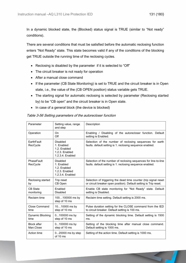
Instruction manual –AQ L310 Line Protection IED 131 (180)
In a dynamic blocked state, the (Blocked) status signal is TRUE (similar to “Not ready”
conditions).
There are several conditions that must be satisfied before the automatic reclosing function
enters “Not Ready” state. This state becomes valid if any of the conditions of the blocking
get TRUE outside the running time of the reclosing cycles.
Reclosing is disabled by the parameter if it is selected to “Off”
The circuit breaker is not ready for operation
After a manual close command
If the parameter (CB State Monitoring) is set to TRUE and the circuit breaker is in Open
state, i.e., the value of the (CB OPEN position) status variable gets TRUE.
The starting signal for automatic reclosing is selected by parameter (Reclosing started
by) to be “CB open” and the circuit breaker is in Open state.
In case of a general block (the device is blocked)
Table 3-56 Setting parameters of the autorecloser function
Parameter Setting value, range
and step
Description
Operation On
Off
Enabling / Disabling of the autorecloser function. Default
setting is Enabled.
EarthFault
RecCycle
Disabled
1. Enabled
1.2. Enabled
1.2.3. Enabled
1.2.3.4. Enabled
Selection of the number of reclosing sequences for earth
faults. default setting is 1. reclosing sequence enabled.
PhaseFault
RecCycle
Disabled
1. Enabled
1.2. Enabled
1.2.3. Enabled
1.2.3.4. Enabled
Selection of the number of reclosing sequences for line-to-line
faults. default setting is 1. reclosing sequence enabled.
Reclosing started
by
Trip reset
CB Open
Selection of triggering the dead time counter (trip signal reset
or circuit breaker open position). Default setting is Trip reset.
CB State
monitoring
Enabled
Disabled
Enable CB state monitoring for “Not Ready” state. Default
setting is Disabled.
Reclaim time 100…100000 ms by
step of 10 ms
Reclaim time setting. Default setting is 2000 ms.
Close Command
time
10…10000 ms by
step of 10 ms
Pulse duration setting for the CLOSE command from the IED
to circuit breaker. Default setting is 100 ms.
Dynamic Blocking
time
0...100000 ms by
step of 10 ms
Setting of the dynamic blocking time. Default setting is 1500
ms.
Block after
Man.Close
0...100000 ms by
step of 10 ms
Setting of the blocking time after manual close command.
Default setting is 1000 ms.
Action time 0...20000 ms by step
of 10 ms
Setting of the action time. Default setting is 1000 ms.

Instruction manual –AQ L310 Line Protection IED 132 (180)
Start-signal
Max.Tim
0...10000 ms by step
of 10 ms
Time limitation of the starting signal. Default setting is 1000
ms.
DeadTime
Max.Delay
0...1000000 ms by
step of 10 ms
Delaying the start of the dead-time counter. Default setting is
3000 ms.
CB Supervision
Time
10...100000 ms by
step of 10 ms
Waiting time for circuit breaker ready signal. Default setting is
1000 ms.
Sync-check
Max.Tim
500...100000 ms by
step of 10 ms
Waiting time for synchronous state signal. Default setting is
10000 ms.
Sync-switch
Max.Tim
500...100000 ms by
step of 10 ms
Waiting time for synchronous switching. Default setting is
10000 ms.
1.Dead Time Ph 0...100000 ms by
step of 10 ms
Dead time setting for the first reclosing cycle for line-to-line
fault. Default setting is 500 ms.
2.Dead Time Ph 10...100000 ms by
step of 10 ms
Dead time setting for the second reclosing cycle for line-to-line
fault. Default setting is 600 ms.
3.Dead Time Ph 10...100000 ms by
step of 10 ms
Dead time setting for the third reclosing cycle for line-to-line
fault. Default setting is 700 ms.
4.Dead Time Ph 10...100000 ms by
step of 10 ms
Dead time setting for the fourth reclosing cycle for line-to-line
fault. Default setting is 800 ms.
1.Dead Time Ef 0...100000 ms by
step of 10 ms
Dead time setting for the first reclosing cycle for earth fault.
Default setting is 1000 ms.
2.Dead Time Ef 10...100000 ms by
step of 10 ms
Dead time setting for the second reclosing cycle for earth fault.
Default setting is 2000 ms.
3.Dead Time Ef 10...100000 ms by
step of 10 ms
Dead time setting for the third reclosing cycle for earth fault.
Default setting is 3000 ms.
4.Dead Time Ef 10...100000 ms by
step of 10 ms
Dead time setting for the fourth reclosing cycle for earth fault.
Default setting is 4000 ms.
Accelerate 1. Trip Enabled
Disabled
Acceleration of the 1st reclosing cycle trip command. Default
setting is Disabled.
Accelerate 2. Trip Enabled
Disabled
Acceleration of the 2nd reclosing cycle trip command. Default
setting is Disabled.
Accelerate 3. Trip Enabled
Disabled
Acceleration of the 3rd reclosing cycle trip command. Default
setting is Disabled.
Accelerate 4. Trip Enabled
Disabled
Acceleration of the 4th reclosing cycle trip command. Default
setting is Disabled.
Accelerate final
Trip
Enabled
Disabled
Acceleration of the final trip command. Default setting is
Disabled.
3.3.7 SWITCH ON TO FAULT LOGIC
Some protection functions, e.g. distance protection, directional overcurrent protection, etc.
need to decide the direction of the fault. This decision is based on the angle between the
voltage and the current. In case of close-in faults, however, the voltage of the faulty loop is
near zero: it is not sufficient for a directional decision. If there are no healthy phases, then
the voltage samples stored in the memory are applied to decide if the fault is forward or
reverse.
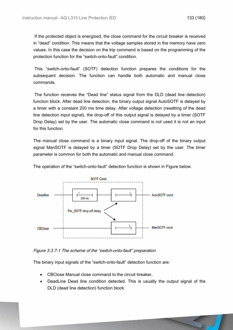
Instruction manual –AQ L310 Line Protection IED 133 (180)
If the protected object is energized, the close command for the circuit breaker is received
in “dead” condition. This means that the voltage samples stored in the memory have zero
values. In this case the decision on the trip command is based on the programming of the
protection function for the “switch-onto-fault” condition.
This “switch-onto-fault” (SOTF) detection function prepares the conditions for the
subsequent decision. The function can handle both automatic and manual close
commands.
The function receives the “Dead line” status signal from the DLD (dead line detection)
function block. After dead line detection, the binary output signal AutoSOTF is delayed by
a timer with a constant 200 ms time delay. After voltage detection (resetting of the dead
line detection input signal), the drop-off of this output signal is delayed by a timer (SOTF
Drop Delay) set by the user. The automatic close command is not used it is not an input
for this function.
The manual close command is a binary input signal. The drop-off of the binary output
signal ManSOTF is delayed by a timer (SOTF Drop Delay) set by the user. The timer
parameter is common for both the automatic and manual close command.
The operation of the “switch-onto-fault” detection function is shown in Figure below.
Figure 3.3.7-1 The scheme of the “switch-onto-fault” preparation
The binary input signals of the “switch-onto-fault” detection function are:
CBClose Manual close command to the circuit breaker,
DeadLine Dead line condition detected. This is usually the output signal of the
DLD (dead line detection) function block.
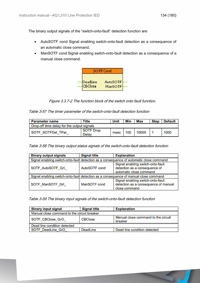
Instruction manual –AQ L310 Line Protection IED 134 (180)
The binary output signals of the “switch-onto-fault” detection function are:
AutoSOTF cond Signal enabling switch-onto-fault detection as a consequence of
an automatic close command,
ManSOTF cond Signal enabling switch-onto-fault detection as a consequence of a
manual close command.
Figure 3.3.7-2 The function block of the switch onto fault function.
Table 3-57 The timer parameter of the switch-onto-fault detection function
Table 3-58 The binary output status signals of the switch-onto-fault detection function
Table 3-59 The binary input signals of the switch-onto-fault detection function
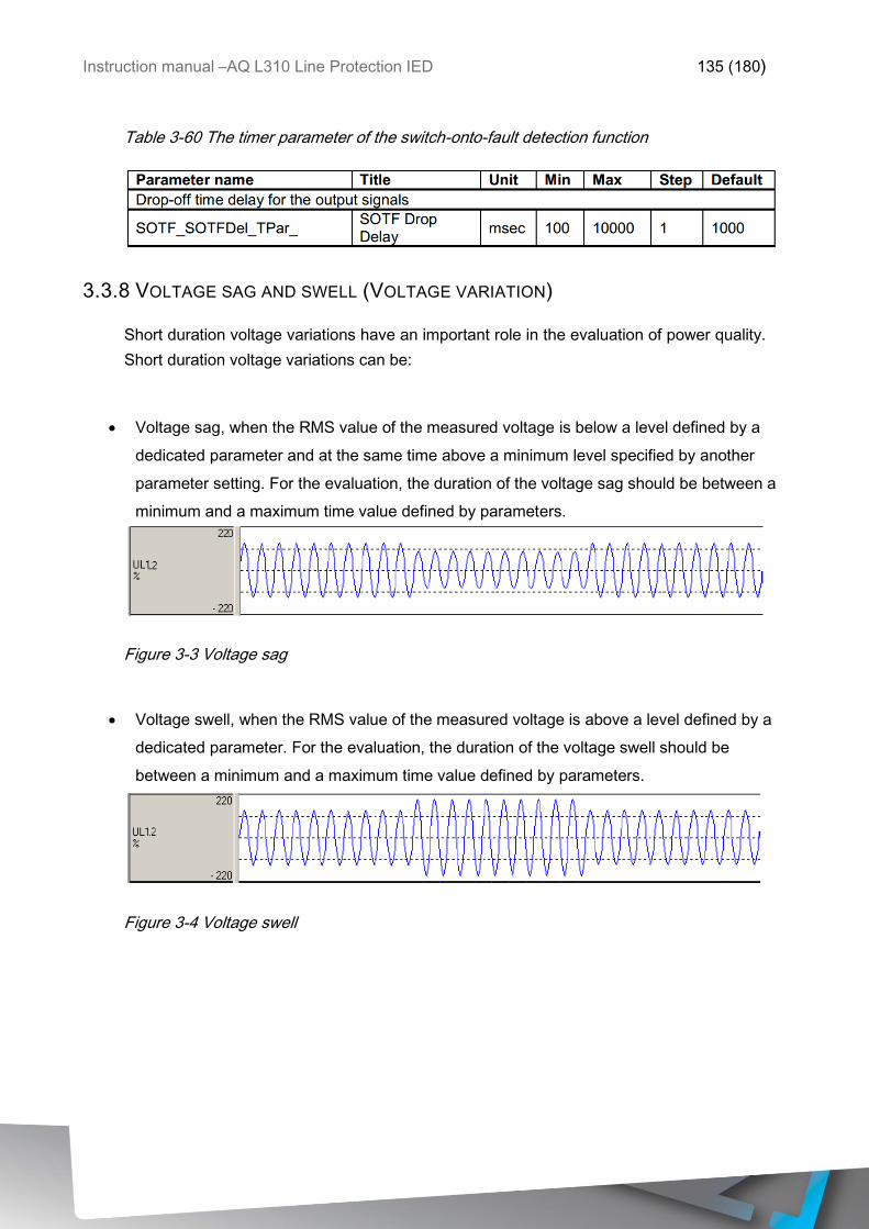
Instruction manual –AQ L310 Line Protection IED 135 (180)
Table 3-60 The timer parameter of the switch-onto-fault detection function
3.3.8 VOLTAGE SAG AND SWELL (VOLTAGE VARIATION)
Short duration voltage variations have an important role in the evaluation of power quality.
Short duration voltage variations can be:
Voltage sag, when the RMS value of the measured voltage is below a level defined by a
dedicated parameter and at the same time above a minimum level specified by another
parameter setting. For the evaluation, the duration of the voltage sag should be between a
minimum and a maximum time value defined by parameters.
Figure 3-3 Voltage sag
Voltage swell, when the RMS value of the measured voltage is above a level defined by a
dedicated parameter. For the evaluation, the duration of the voltage swell should be
between a minimum and a maximum time value defined by parameters.
Figure 3-4 Voltage swell
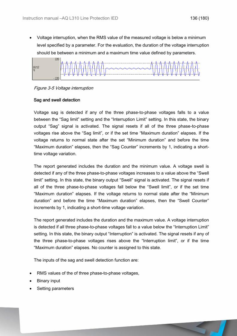
Instruction manual –AQ L310 Line Protection IED 136 (180)
Voltage interruption, when the RMS value of the measured voltage is below a minimum
level specified by a parameter. For the evaluation, the duration of the voltage interruption
should be between a minimum and a maximum time value defined by parameters.
Figure 3-5 Voltage interruption
Sag and swell detection
Voltage sag is detected if any of the three phase-to-phase voltages falls to a value
between the “Sag limit” setting and the “Interruption Limit” setting. In this state, the binary
output “Sag” signal is activated. The signal resets if all of the three phase-to-phase
voltages rise above the “Sag limit”, or if the set time “Maximum duration” elapses. If the
voltage returns to normal state after the set “Minimum duration” and before the time
“Maximum duration” elapses, then the “Sag Counter” increments by 1, indicating a short-
time voltage variation.
The report generated includes the duration and the minimum value. A voltage swell is
detected if any of the three phase-to-phase voltages increases to a value above the “Swell
limit” setting. In this state, the binary output “Swell” signal is activated. The signal resets if
all of the three phase-to-phase voltages fall below the “Swell limit”, or if the set time
“Maximum duration” elapses. If the voltage returns to normal state after the “Minimum
duration” and before the time “Maximum duration” elapses, then the “Swell Counter”
increments by 1, indicating a short-time voltage variation.
The report generated includes the duration and the maximum value. A voltage interruption
is detected if all three phase-to-phase voltages fall to a value below the “Interruption Limit”
setting. In this state, the binary output “Interruption” is activated. The signal resets if any of
the three phase-to-phase voltages rises above the “Interruption limit”, or if the time
“Maximum duration” elapses. No counter is assigned to this state.
The inputs of the sag and swell detection function are:
RMS values of the of three phase-to-phase voltages,
Binary input
Setting parameters
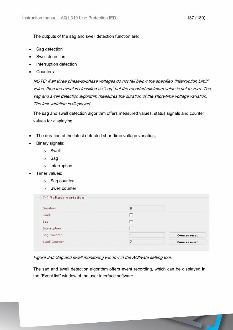
Instruction manual –AQ L310 Line Protection IED 137 (180)
The outputs of the sag and swell detection function are:
Sag detection
Swell detection
Interruption detection
Counters
NOTE: if all three phase-to-phase voltages do not fall below the specified “Interruption Limit”
value, then the event is classified as “sag” but the reported minimum value is set to zero. The
sag and swell detection algorithm measures the duration of the short-time voltage variation.
The last variation is displayed.
The sag and swell detection algorithm offers measured values, status signals and counter
values for displaying:
The duration of the latest detected short-time voltage variation,
Binary signals:
o Swell
o Sag
o Interruption
Timer values:
o Sag counter
o Swell counter
Figure 3-6: Sag and swell monitoring window in the AQtivate setting tool.
The sag and swell detection algorithm offers event recording, which can be displayed in
the “Event list” window of the user interface software.
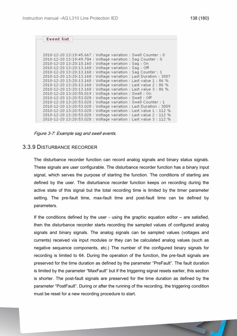
Instruction manual –AQ L310 Line Protection IED 138 (180)
Figure 3-7: Example sag and swell events.
3.3.9 DISTURBANCE RECORDER
The disturbance recorder function can record analog signals and binary status signals.
These signals are user configurable. The disturbance recorder function has a binary input
signal, which serves the purpose of starting the function. The conditions of starting are
defined by the user. The disturbance recorder function keeps on recording during the
active state of this signal but the total recording time is limited by the timer parameter
setting. The pre-fault time, max-fault time and post-fault time can be defined by
parameters.
If the conditions defined by the user - using the graphic equation editor – are satisfied,
then the disturbance recorder starts recording the sampled values of configured analog
signals and binary signals. The analog signals can be sampled values (voltages and
currents) received via input modules or they can be calculated analog values (such as
negative sequence components, etc.) The number of the configured binary signals for
recording is limited to 64. During the operation of the function, the pre-fault signals are
preserved for the time duration as defined by the parameter “PreFault”. The fault duration
is limited by the parameter “MaxFault” but if the triggering signal resets earlier, this section
is shorter. The post-fault signals are preserved for the time duration as defined by the
parameter “PostFault”. During or after the running of the recording, the triggering condition
must be reset for a new recording procedure to start.
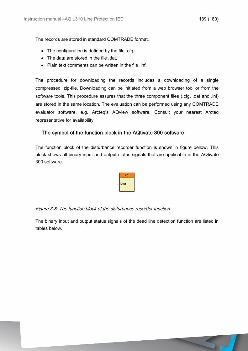
Instruction manual –AQ L310 Line Protection IED 139 (180)
The records are stored in standard COMTRADE format.
The configuration is defined by the file .cfg,
The data are stored in the file .dat,
Plain text comments can be written in the file .inf.
The procedure for downloading the records includes a downloading of a single
compressed .zip-file. Downloading can be initiated from a web browser tool or from the
software tools. This procedure assures that the three component files (.cfg, .dat and .inf)
are stored in the same location. The evaluation can be performed using any COMTRADE
evaluator software, e.g. Arcteq’s AQview software. Consult your nearest Arcteq
representative for availability.
The symbol of the function block in the AQtivate 300 software
The function block of the disturbance recorder function is shown in figure bellow. This
block shows all binary input and output status signals that are applicable in the AQtivate
300 software.
Figure 3-8: The function block of the disturbance recorder function
The binary input and output status signals of the dead line detection function are listed in
tables below.
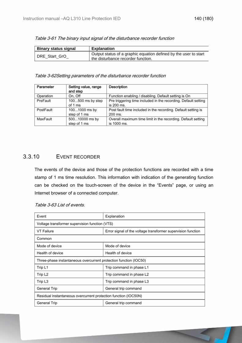
Instruction manual –AQ L310 Line Protection IED 140 (180)
Table 3-61 The binary input signal of the disturbance recorder function
Binary status signal Explanation
DRE_Start_GrO_ Output status of a graphic equation defined by the user to start the disturbance recorder function.
Table 3-62Setting parameters of the disturbance recorder function
Parameter Setting value, range
and step
Description
Operation On, Off Function enabling / disabling. Default setting is On
PreFault 100...500 ms by step
of 1 ms
Pre triggering time included in the recording. Default setting
is 200 ms.
PostFault 100...1000 ms by
step of 1 ms
Post fault time included in the recording. Default setting is
200 ms.
MaxFault 500...10000 ms by
step of 1 ms
Overall maximum time limit in the recording. Default setting
is 1000 ms.
3.3.10 EVENT RECORDER
The events of the device and those of the protection functions are recorded with a time
stamp of 1 ms time resolution. This information with indication of the generating function
can be checked on the touch-screen of the device in the “Events” page, or using an
Internet browser of a connected computer.
Table 3-63 List of events.
Event Explanation
Voltage transformer supervision function (VTS)
VT Failure Error signal of the voltage transformer supervision function
Common
Mode of device Mode of device
Health of device Health of device
Three-phase instantaneous overcurrent protection function (IOC50)
Trip L1 Trip command in phase L1
Trip L2 Trip command in phase L2
Trip L3 Trip command in phase L3
General Trip General trip command
Residual instantaneous overcurrent protection function (IOC50N)
General Trip General trip command
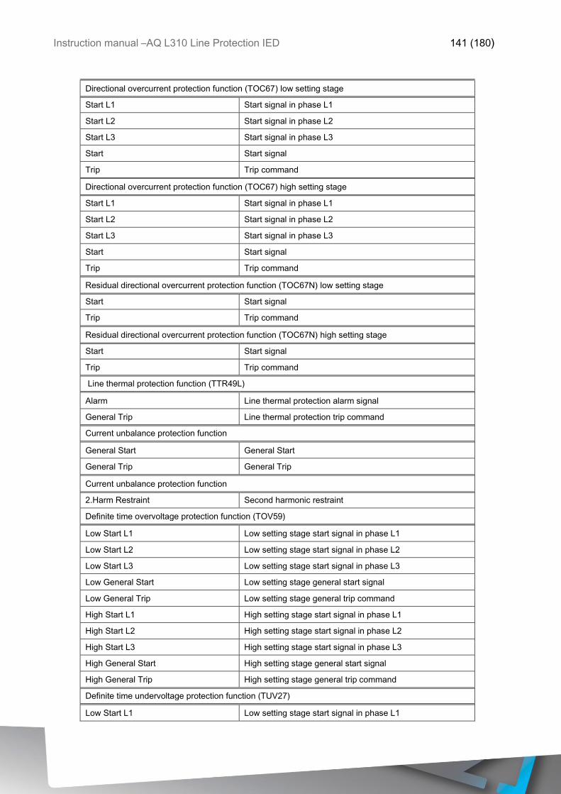
Instruction manual –AQ L310 Line Protection IED 141 (180)
Directional overcurrent protection function (TOC67) low setting stage
Start L1 Start signal in phase L1
Start L2 Start signal in phase L2
Start L3 Start signal in phase L3
Start Start signal
Trip Trip command
Directional overcurrent protection function (TOC67) high setting stage
Start L1 Start signal in phase L1
Start L2 Start signal in phase L2
Start L3 Start signal in phase L3
Start Start signal
Trip Trip command
Residual directional overcurrent protection function (TOC67N) low setting stage
Start Start signal
Trip Trip command
Residual directional overcurrent protection function (TOC67N) high setting stage
Start Start signal
Trip Trip command
Line thermal protection function (TTR49L)
Alarm Line thermal protection alarm signal
General Trip Line thermal protection trip command
Current unbalance protection function
General Start General Start
General Trip General Trip
Current unbalance protection function
2.Harm Restraint Second harmonic restraint
Definite time overvoltage protection function (TOV59)
Low Start L1 Low setting stage start signal in phase L1
Low Start L2 Low setting stage start signal in phase L2
Low Start L3 Low setting stage start signal in phase L3
Low General Start Low setting stage general start signal
Low General Trip Low setting stage general trip command
High Start L1 High setting stage start signal in phase L1
High Start L2 High setting stage start signal in phase L2
High Start L3 High setting stage start signal in phase L3
High General Start High setting stage general start signal
High General Trip High setting stage general trip command
Definite time undervoltage protection function (TUV27)
Low Start L1 Low setting stage start signal in phase L1
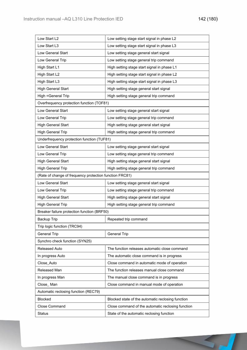
Instruction manual –AQ L310 Line Protection IED 142 (180)
Low Start L2 Low setting stage start signal in phase L2
Low Start L3 Low setting stage start signal in phase L3
Low General Start Low setting stage general start signal
Low General Trip Low setting stage general trip command
High Start L1 High setting stage start signal in phase L1
High Start L2 High setting stage start signal in phase L2
High Start L3 High setting stage start signal in phase L3
High General Start High setting stage general start signal
High =General Trip High setting stage general trip command
Overfrequency protection function (TOF81)
Low General Start Low setting stage general start signal
Low General Trip Low setting stage general trip command
High General Start High setting stage general start signal
High General Trip High setting stage general trip command
Underfrequency protection function (TUF81)
Low General Start Low setting stage general start signal
Low General Trip Low setting stage general trip command
High General Start High setting stage general start signal
High General Trip High setting stage general trip command
(Rate of change of frequency protection function FRC81)
Low General Start Low setting stage general start signal
Low General Trip Low setting stage general trip command
High General Start High setting stage general start signal
High General Trip High setting stage general trip command
Breaker failure protection function (BRF50)
Backup Trip Repeated trip command
Trip logic function (TRC94)
General Trip General Trip
Synchro check function (SYN25)
Released Auto The function releases automatic close command
In progress Auto The automatic close command is in progress
Close_Auto Close command in automatic mode of operation
Released Man The function releases manual close command
In progress Man The manual close command is in progress
Close_ Man Close command in manual mode of operation
Automatic reclosing function (REC79)
Blocked Blocked state of the automatic reclosing function
Close Command Close command of the automatic reclosing function
Status State of the automatic reclosing function
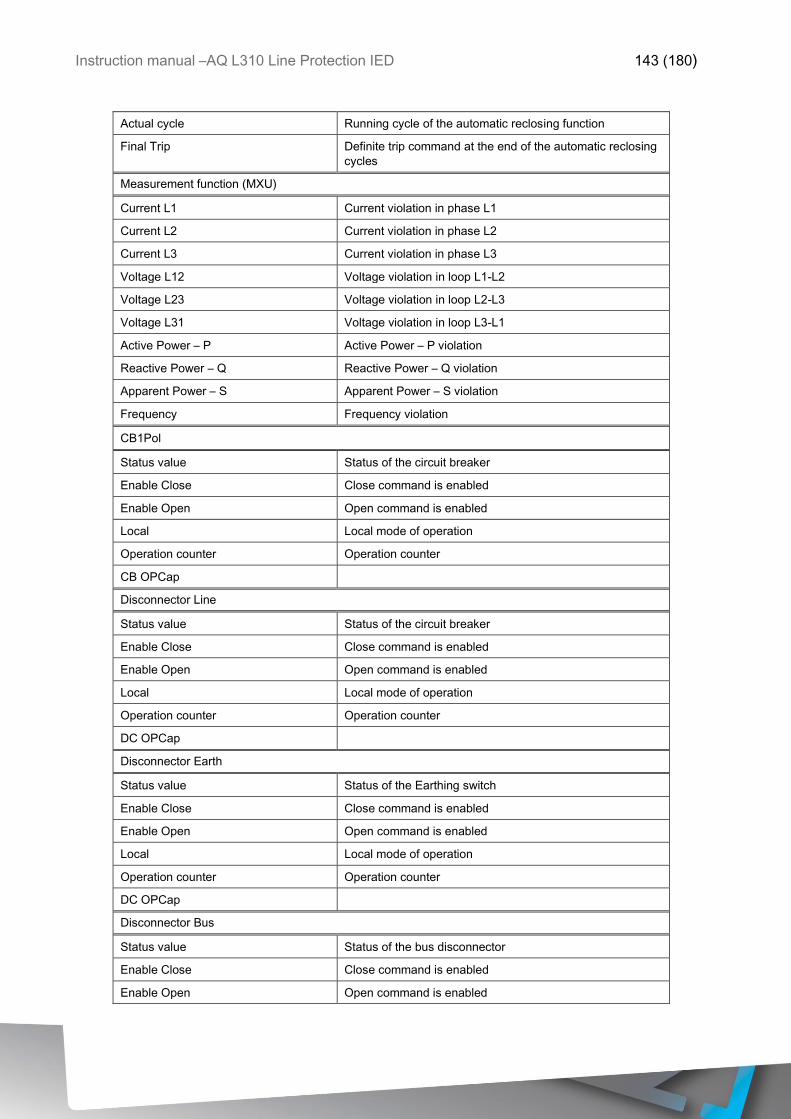
Instruction manual –AQ L310 Line Protection IED 143 (180)
Actual cycle Running cycle of the automatic reclosing function
Final Trip Definite trip command at the end of the automatic reclosing
cycles
Measurement function (MXU)
Current L1 Current violation in phase L1
Current L2 Current violation in phase L2
Current L3 Current violation in phase L3
Voltage L12 Voltage violation in loop L1-L2
Voltage L23 Voltage violation in loop L2-L3
Voltage L31 Voltage violation in loop L3-L1
Active Power – P Active Power – P violation
Reactive Power – Q Reactive Power – Q violation
Apparent Power – S Apparent Power – S violation
Frequency Frequency violation
CB1Pol
Status value Status of the circuit breaker
Enable Close Close command is enabled
Enable Open Open command is enabled
Local Local mode of operation
Operation counter Operation counter
CB OPCap
Disconnector Line
Status value Status of the circuit breaker
Enable Close Close command is enabled
Enable Open Open command is enabled
Local Local mode of operation
Operation counter Operation counter
DC OPCap
Disconnector Earth
Status value Status of the Earthing switch
Enable Close Close command is enabled
Enable Open Open command is enabled
Local Local mode of operation
Operation counter Operation counter
DC OPCap
Disconnector Bus
Status value Status of the bus disconnector
Enable Close Close command is enabled
Enable Open Open command is enabled
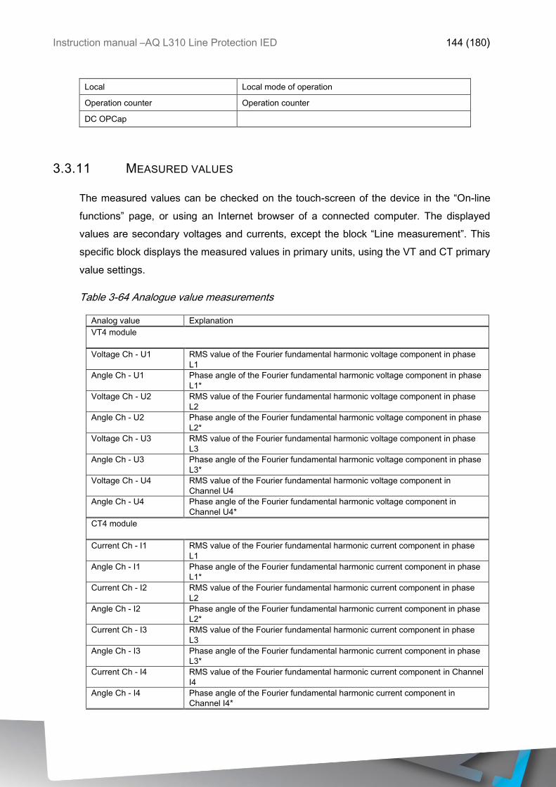
Instruction manual –AQ L310 Line Protection IED 144 (180)
Local Local mode of operation
Operation counter Operation counter
DC OPCap
3.3.11 MEASURED VALUES
The measured values can be checked on the touch-screen of the device in the “On-line
functions” page, or using an Internet browser of a connected computer. The displayed
values are secondary voltages and currents, except the block “Line measurement”. This
specific block displays the measured values in primary units, using the VT and CT primary
value settings.
Table 3-64 Analogue value measurements
Analog value Explanation
VT4 module
Voltage Ch - U1 RMS value of the Fourier fundamental harmonic voltage component in phase
L1
Angle Ch - U1 Phase angle of the Fourier fundamental harmonic voltage component in phase
L1*
Voltage Ch - U2 RMS value of the Fourier fundamental harmonic voltage component in phase
L2
Angle Ch - U2 Phase angle of the Fourier fundamental harmonic voltage component in phase
L2*
Voltage Ch - U3 RMS value of the Fourier fundamental harmonic voltage component in phase
L3
Angle Ch - U3 Phase angle of the Fourier fundamental harmonic voltage component in phase
L3*
Voltage Ch - U4 RMS value of the Fourier fundamental harmonic voltage component in
Channel U4
Angle Ch - U4 Phase angle of the Fourier fundamental harmonic voltage component in
Channel U4*
CT4 module
Current Ch - I1 RMS value of the Fourier fundamental harmonic current component in phase
L1
Angle Ch - I1 Phase angle of the Fourier fundamental harmonic current component in phase
L1*
Current Ch - I2 RMS value of the Fourier fundamental harmonic current component in phase
L2
Angle Ch - I2 Phase angle of the Fourier fundamental harmonic current component in phase
L2*
Current Ch - I3 RMS value of the Fourier fundamental harmonic current component in phase
L3
Angle Ch - I3 Phase angle of the Fourier fundamental harmonic current component in phase
L3*
Current Ch - I4 RMS value of the Fourier fundamental harmonic current component in Channel
I4
Angle Ch - I4 Phase angle of the Fourier fundamental harmonic current component in
Channel I4*
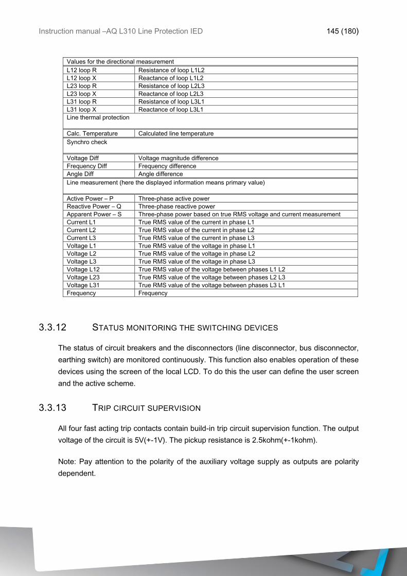
Instruction manual –AQ L310 Line Protection IED 145 (180)
Values for the directional measurement
L12 loop R Resistance of loop L1L2
L12 loop X Reactance of loop L1L2
L23 loop R Resistance of loop L2L3
L23 loop X Reactance of loop L2L3
L31 loop R Resistance of loop L3L1
L31 loop X Reactance of loop L3L1
Line thermal protection
Calc. Temperature Calculated line temperature
Synchro check
Voltage Diff Voltage magnitude difference
Frequency Diff Frequency difference
Angle Diff Angle difference
Line measurement (here the displayed information means primary value)
Active Power – P Three-phase active power
Reactive Power – Q Three-phase reactive power
Apparent Power – S Three-phase power based on true RMS voltage and current measurement
Current L1 True RMS value of the current in phase L1
Current L2 True RMS value of the current in phase L2
Current L3 True RMS value of the current in phase L3
Voltage L1 True RMS value of the voltage in phase L1
Voltage L2 True RMS value of the voltage in phase L2
Voltage L3 True RMS value of the voltage in phase L3
Voltage L12 True RMS value of the voltage between phases L1 L2
Voltage L23 True RMS value of the voltage between phases L2 L3
Voltage L31 True RMS value of the voltage between phases L3 L1
Frequency Frequency
3.3.12 STATUS MONITORING THE SWITCHING DEVICES
The status of circuit breakers and the disconnectors (line disconnector, bus disconnector,
earthing switch) are monitored continuously. This function also enables operation of these
devices using the screen of the local LCD. To do this the user can define the user screen
and the active scheme.
3.3.13 TRIP CIRCUIT SUPERVISION
All four fast acting trip contacts contain build-in trip circuit supervision function. The output
voltage of the circuit is 5V(+-1V). The pickup resistance is 2.5kohm(+-1kohm).
Note: Pay attention to the polarity of the auxiliary voltage supply as outputs are polarity
dependent.
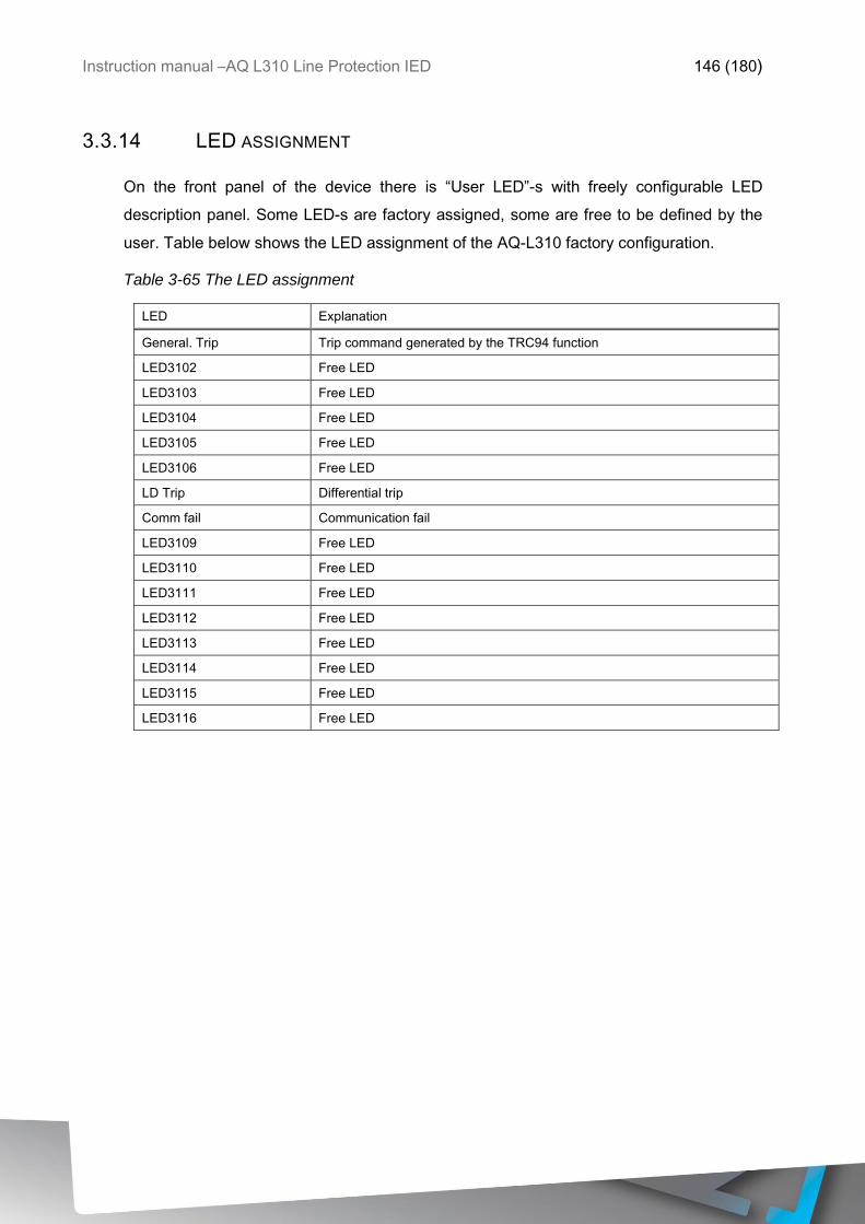
Instruction manual –AQ L310 Line Protection IED 146 (180)
3.3.14 LED ASSIGNMENT
On the front panel of the device there is “User LED”-s with freely configurable LED
description panel. Some LED-s are factory assigned, some are free to be defined by the
user. Table below shows the LED assignment of the AQ-L310 factory configuration.
Table 3-65 The LED assignment
LED Explanation
General. Trip Trip command generated by the TRC94 function
LED3102 Free LED
LED3103 Free LED
LED3104 Free LED
LED3105 Free LED
LED3106 Free LED
LD Trip Differential trip
Comm fail Communication fail
LED3109 Free LED
LED3110 Free LED
LED3111 Free LED
LED3112 Free LED
LED3113 Free LED
LED3114 Free LED
LED3115 Free LED
LED3116 Free LED
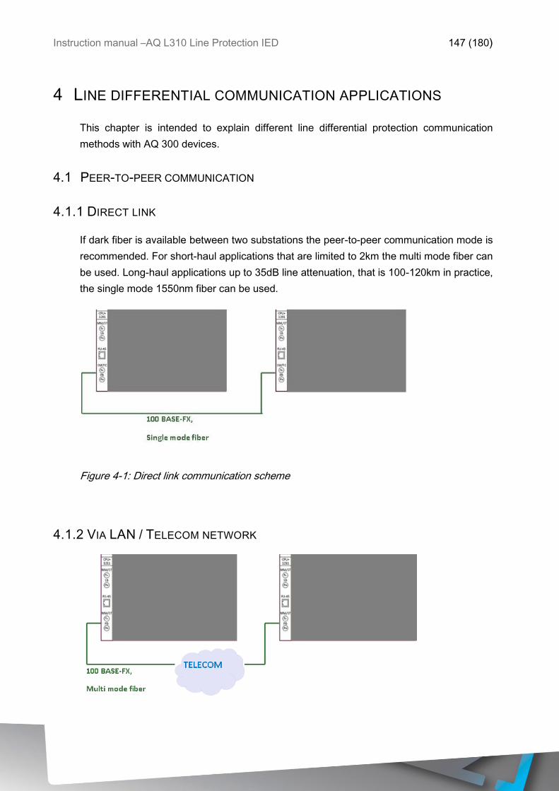
Instruction manual –AQ L310 Line Protection IED 147 (180)
4 LINE DIFFERENTIAL COMMUNICATION APPLICATIONS
This chapter is intended to explain different line differential protection communication
methods with AQ 300 devices.
4.1 PEER-TO-PEER COMMUNICATION
4.1.1 DIRECT LINK
If dark fiber is available between two substations the peer-to-peer communication mode is
recommended. For short-haul applications that are limited to 2km the multi mode fiber can
be used. Long-haul applications up to 35dB line attenuation, that is 100-120km in practice,
the single mode 1550nm fiber can be used.
Figure 4-1: Direct link communication scheme
4.1.2 VIA LAN / TELECOM NETWORK
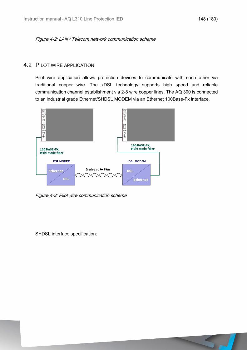
Instruction manual –AQ L310 Line Protection IED 148 (180)
Figure 4-2: LAN / Telecom network communication scheme
4.2 PILOT WIRE APPLICATION
Pilot wire application allows protection devices to communicate with each other via
traditional copper wire. The xDSL technology supports high speed and reliable
communication channel establishment via 2-8 wire copper lines. The AQ 300 is connected
to an industrial grade Ethernet/SHDSL MODEM via an Ethernet 100Base-Fx interface.
Figure 4-3: Pilot wire communication scheme
SHDSL interface specification:
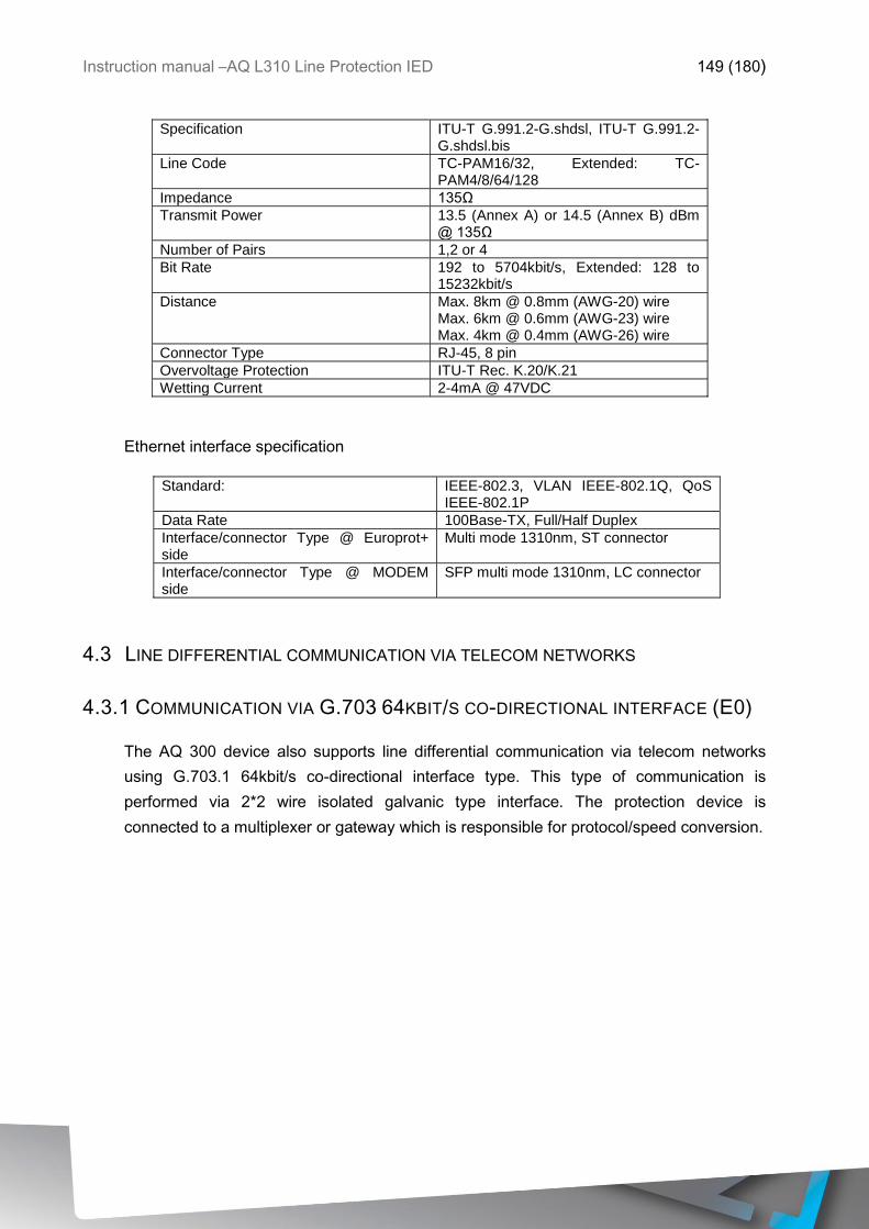
Instruction manual –AQ L310 Line Protection IED 149 (180)
Specification ITU-T G.991.2-G.shdsl, ITU-T G.991.2-G.shdsl.bis
Line Code TC-PAM16/32, Extended: TC-PAM4/8/64/128
Impedance 135Ω
Transmit Power 13.5 (Annex A) or 14.5 (Annex B) dBm @ 135Ω
Number of Pairs 1,2 or 4
Bit Rate 192 to 5704kbit/s, Extended: 128 to 15232kbit/s
Distance Max. 8km @ 0.8mm (AWG-20) wire Max. 6km @ 0.6mm (AWG-23) wire Max. 4km @ 0.4mm (AWG-26) wire
Connector Type RJ-45, 8 pin
Overvoltage Protection ITU-T Rec. K.20/K.21
Wetting Current 2-4mA @ 47VDC
Ethernet interface specification
Standard: IEEE-802.3, VLAN IEEE-802.1Q, QoS IEEE-802.1P
Data Rate 100Base-TX, Full/Half Duplex
Interface/connector Type @ Europrot+ side
Multi mode 1310nm, ST connector
Interface/connector Type @ MODEM side
SFP multi mode 1310nm, LC connector
4.3 LINE DIFFERENTIAL COMMUNICATION VIA TELECOM NETWORKS
4.3.1 COMMUNICATION VIA G.703 64KBIT/S CO-DIRECTIONAL INTERFACE (E0)
The AQ 300 device also supports line differential communication via telecom networks
using G.703.1 64kbit/s co-directional interface type. This type of communication is
performed via 2*2 wire isolated galvanic type interface. The protection device is
connected to a multiplexer or gateway which is responsible for protocol/speed conversion.
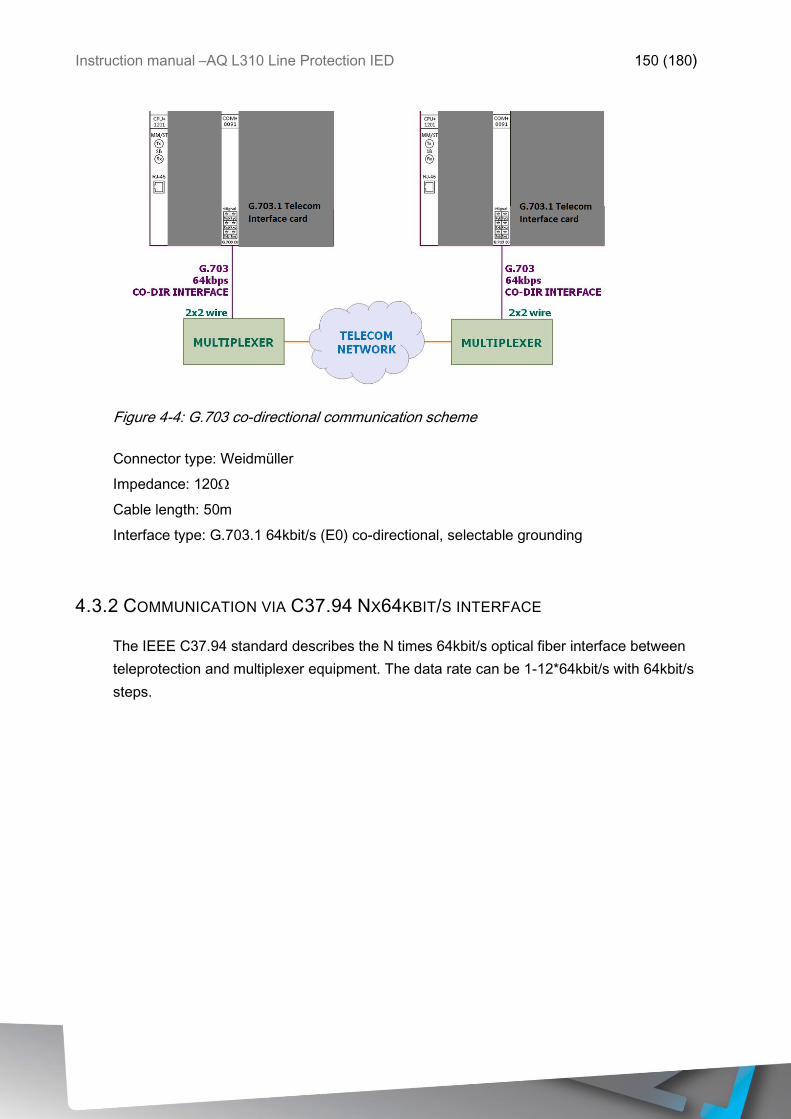
Instruction manual –AQ L310 Line Protection IED 150 (180)
Figure 4-4: G.703 co-directional communication scheme
Connector type: Weidmüller
Impedance: 120Ω
Cable length: 50m
Interface type: G.703.1 64kbit/s (E0) co-directional, selectable grounding
4.3.2 COMMUNICATION VIA C37.94 NX64KBIT/S INTERFACE
The IEEE C37.94 standard describes the N times 64kbit/s optical fiber interface between
teleprotection and multiplexer equipment. The data rate can be 1-12*64kbit/s with 64kbit/s
steps.
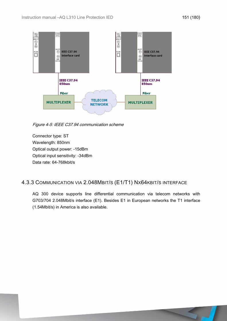
Instruction manual –AQ L310 Line Protection IED 151 (180)
Figure 4-5: IEEE C37.94 communication scheme
Connector type: ST
Wavelength: 850nm
Optical output power: -15dBm
Optical input sensitivity: -34dBm
Data rate: 64-768kbit/s
4.3.3 COMMUNICATION VIA 2.048MBIT/S (E1/T1) NX64KBIT/S INTERFACE
AQ 300 device supports line differential communication via telecom networks with
G703/704 2.048Mbit/s interface (E1). Besides E1 in European networks the T1 interface
(1.54Mbit/s) in America is also available.
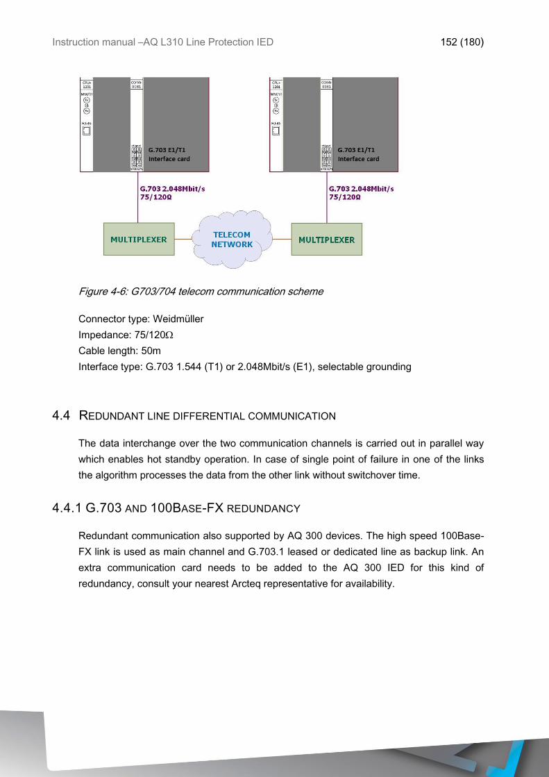
Instruction manual –AQ L310 Line Protection IED 152 (180)
Figure 4-6: G703/704 telecom communication scheme
Connector type: Weidmüller
Impedance: 75/120Ω
Cable length: 50m
Interface type: G.703 1.544 (T1) or 2.048Mbit/s (E1), selectable grounding
4.4 REDUNDANT LINE DIFFERENTIAL COMMUNICATION
The data interchange over the two communication channels is carried out in parallel way
which enables hot standby operation. In case of single point of failure in one of the links
the algorithm processes the data from the other link without switchover time.
4.4.1 G.703 AND 100BASE-FX REDUNDANCY
Redundant communication also supported by AQ 300 devices. The high speed 100Base-
FX link is used as main channel and G.703.1 leased or dedicated line as backup link. An
extra communication card needs to be added to the AQ 300 IED for this kind of
redundancy, consult your nearest Arcteq representative for availability.
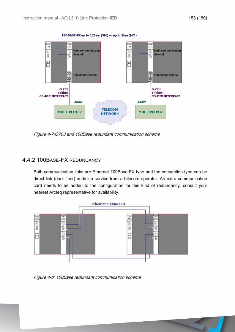
Instruction manual –AQ L310 Line Protection IED 153 (180)
Figure 4-7:G703 and 100Base redundant communication scheme
4.4.2 100BASE-FX REDUNDANCY
Both communication links are Ethernet 100Base-FX type and the connection type can be
direct link (dark fiber) and/or a service from a telecom operator. An extra communication
card needs to be added to the configuration for this kind of redundancy, consult your
nearest Arcteq representative for availability.
Figure 4-8: 100Base redundant communication scheme
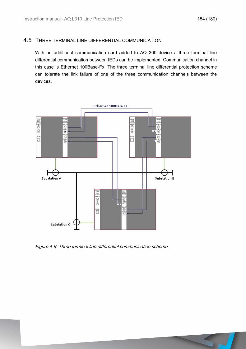
Instruction manual –AQ L310 Line Protection IED 154 (180)
4.5 THREE TERMINAL LINE DIFFERENTIAL COMMUNICATION
With an additional communication card added to AQ 300 device a three terminal line
differential communication between IEDs can be implemented. Communication channel in
this case is Ethernet 100Base-Fx. The three terminal line differential protection scheme
can tolerate the link failure of one of the three communication channels between the
devices.
Figure 4-9: Three terminal line differential communication scheme
Instruction manual –AQ L310 Line Protection IED 155 (180)
5 SYSTEM INTEGRATION
The AQ L310 contains two ports for communicating to upper level supervisory system and
one for process bus communication. The physical media or the ports can be either serial
fiber optic or RJ 45 or Ethernet fiber optic. Communication ports are always in the CPU
module of the device.
The AQ L310 line protection IED communicates using IEC 61850, IEC 101, IEC 103, IEC
104, Modbus RTU, DNP3.0 and SPA protocols. For details of each protocol refer to
respective interoperability lists.
For IRIG-B time synchronization binary input module O12 channel 1 can be used.
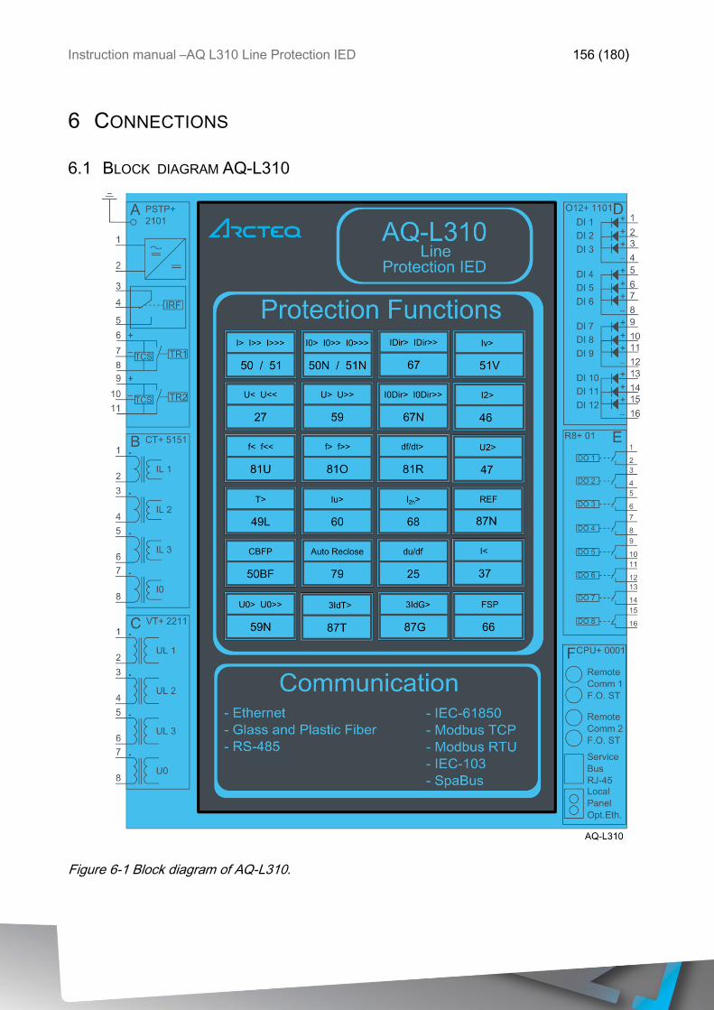
Instruction manual –AQ L310 Line Protection IED 156 (180)
6 CONNECTIONS
6.1 BLOCK DIAGRAM AQ-L310
Figure 6-1 Block diagram of AQ-L310.
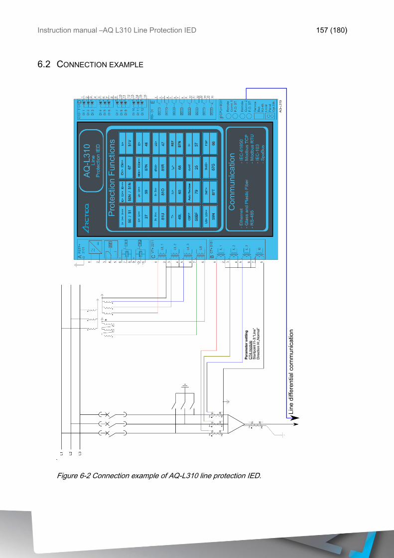
Instruction manual –AQ L310 Line Protection IED 157 (180)
6.2 CONNECTION EXAMPLE
Figure 6-2 Connection example of AQ-L310 line protection IED.
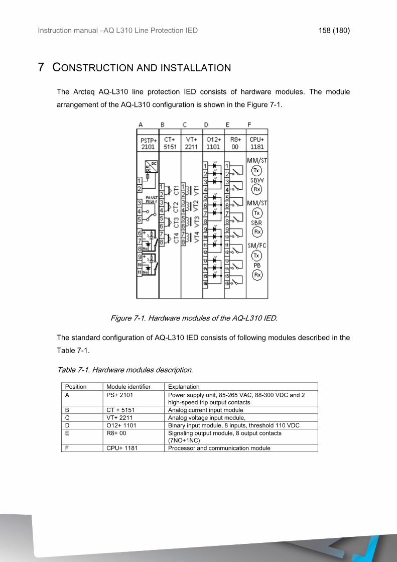
Instruction manual –AQ L310 Line Protection IED 158 (180)
7 CONSTRUCTION AND INSTALLATION
The Arcteq AQ-L310 line protection IED consists of hardware modules. The module
arrangement of the AQ-L310 configuration is shown in the Figure 7-1.
Figure 7-1. Hardware modules of the AQ-L310 IED.
The standard configuration of AQ-L310 IED consists of following modules described in the
Table 7-1.
Table 7-1. Hardware modules description.
Position Module identifier Explanation
A PS+ 2101 Power supply unit, 85-265 VAC, 88-300 VDC and 2
high-speed trip output contacts
B CT + 5151 Analog current input module
C VT+ 2211 Analog voltage input module,
D O12+ 1101 Binary input module, 8 inputs, threshold 110 VDC
E R8+ 00 Signaling output module, 8 output contacts
(7NO+1NC)
F CPU+ 1181 Processor and communication module

Instruction manual –AQ L310 Line Protection IED 159 (180)
7.1 CPU MODULE
The CPU module contains all the protection, control and communication functions of the
AQ 3xx device. Dual 500 MHz high- performance Analog Devices Blackfin processors
separates relay functions (RDSP) from communication and HMI functions (CDSP).
Reliable communication between processors is performed via high- speed synchronous
serial internal bus (SPORT).
Each processor has its own operative memory such as SDRAM and flash memories for
configuration, parameter and firmware storage. CDSP’s operating system (uClinux)
utilizes a robust JFFS flash file system, which enables fail-safe operation and the storage
of, disturbance record files, configuration and parameters.
After power-up the RDSP processor starts -up with the previously saved configuration and
parameters. Generally, the power-up procedure for the RDSP and relay functions takes
approx. 1 sec. That is to say, it is ready to trip within this time. CDSP’s start-up procedure
is longer, because its operating system needs time to build its file system, initializing user
applications such as HMI functions and the IEC61850 software stack.
The built-in 5- port Ethernet switch allows AQ 3xx device to connect to IP/Ethernet- based
networks. The following Ethernet ports are available:
Station bus (100Base-FX Ethernet)
Redundant Station bus (100Base-FX Ethernet)
Process bus (100Base-FX Ethernet)
EOB (Ethernet over Board) user interface
Optional 100Base-Tx port via RJ-45 connector
Other communication
RS422/RS485/RS232 interfaces
Plastic or glass fiber interfaces to support legacy protocols
Process-bus communication controller on COM+ card
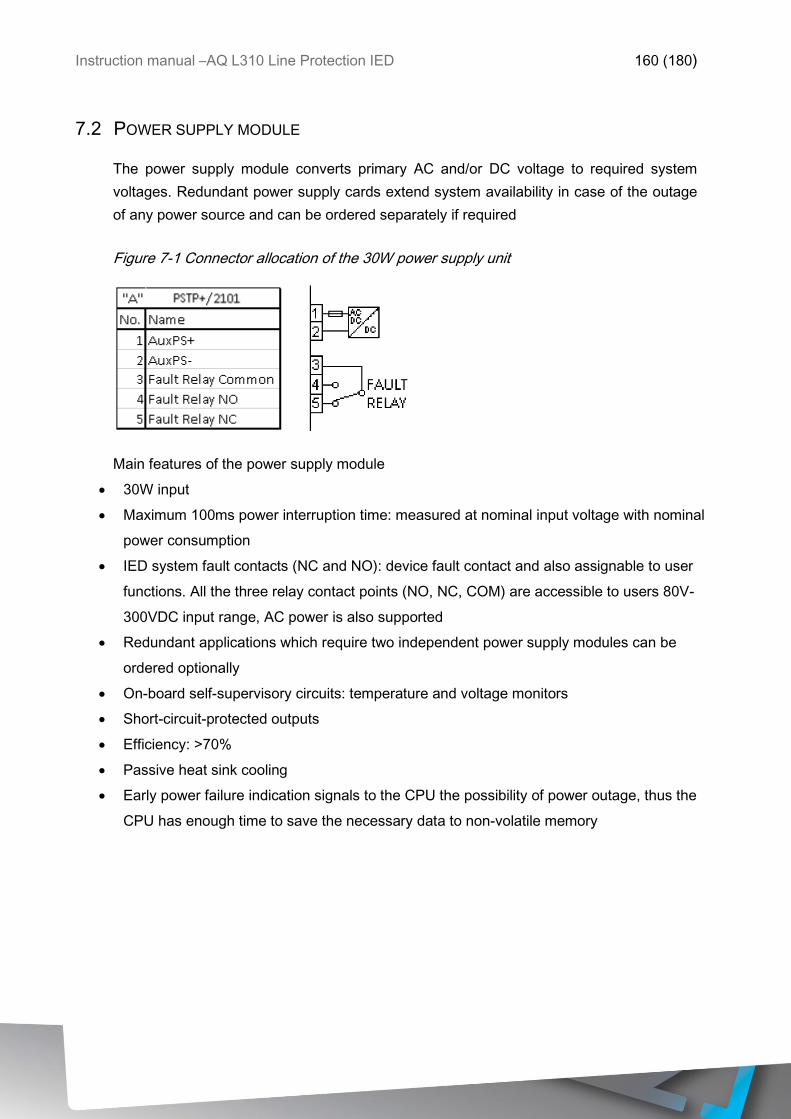
Instruction manual –AQ L310 Line Protection IED 160 (180)
7.2 POWER SUPPLY MODULE
The power supply module converts primary AC and/or DC voltage to required system
voltages. Redundant power supply cards extend system availability in case of the outage
of any power source and can be ordered separately if required
Figure 7-1 Connector allocation of the 30W power supply unit
Main features of the power supply module
30W input
Maximum 100ms power interruption time: measured at nominal input voltage with nominal
power consumption
IED system fault contacts (NC and NO): device fault contact and also assignable to user
functions. All the three relay contact points (NO, NC, COM) are accessible to users 80V-
300VDC input range, AC power is also supported
Redundant applications which require two independent power supply modules can be
ordered optionally
On-board self-supervisory circuits: temperature and voltage monitors
Short-circuit-protected outputs
Efficiency: >70%
Passive heat sink cooling
Early power failure indication signals to the CPU the possibility of power outage, thus the
CPU has enough time to save the necessary data to non-volatile memory
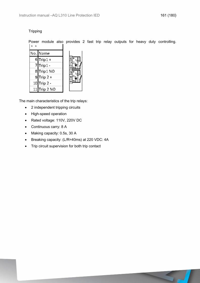
Instruction manual –AQ L310 Line Protection IED 161 (180)
Tripping
Power module also provides 2 fast trip relay outputs for heavy duty controlling.
The main characteristics of the trip relays:
2 independent tripping circuits
High-speed operation
Rated voltage: 110V, 220V DC
Continuous carry: 8 A
Making capacity: 0.5s, 30 A
Breaking capacity: (L/R=40ms) at 220 VDC: 4A
Trip circuit supervision for both trip contact
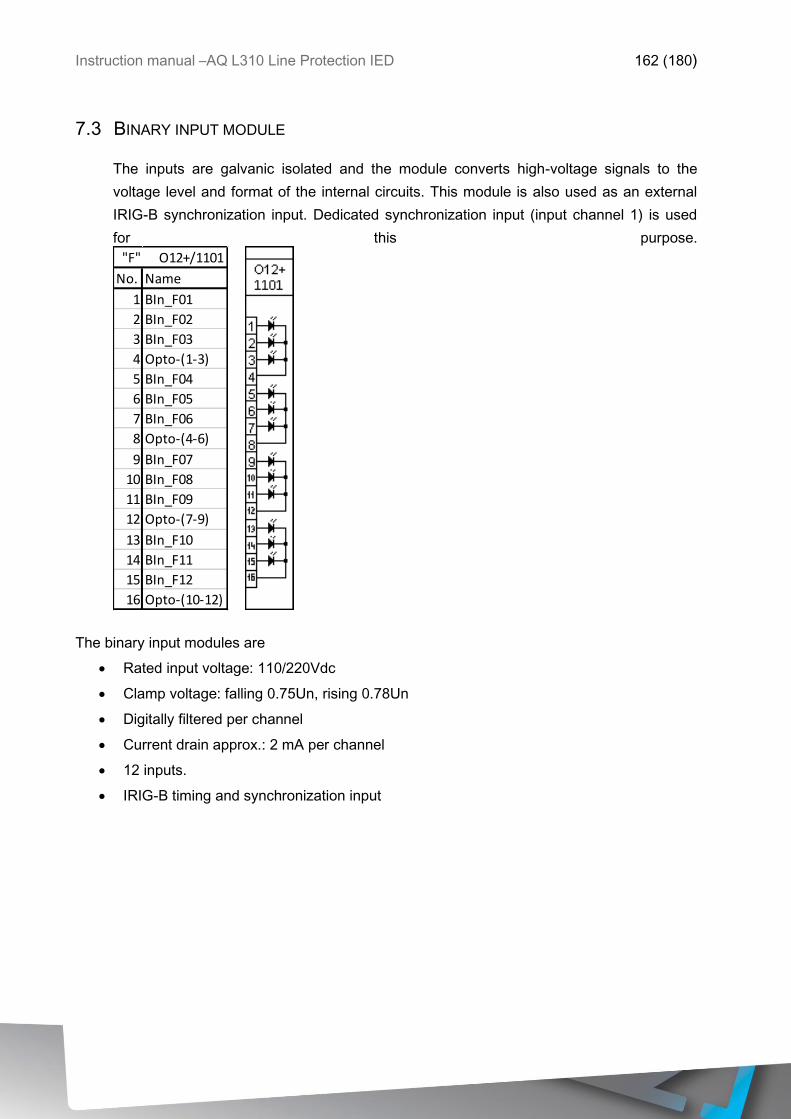
Instruction manual –AQ L310 Line Protection IED 162 (180)
7.3 BINARY INPUT MODULE
The inputs are galvanic isolated and the module converts high-voltage signals to the
voltage level and format of the internal circuits. This module is also used as an external
IRIG-B synchronization input. Dedicated synchronization input (input channel 1) is used
for this purpose.
The binary input modules are
Rated input voltage: 110/220Vdc
Clamp voltage: falling 0.75Un, rising 0.78Un
Digitally filtered per channel
Current drain approx.: 2 mA per channel
12 inputs.
IRIG-B timing and synchronization input
No. Name
1 BIn_F01
2 BIn_F02
3 BIn_F03
4 Opto-(1-3)
5 BIn_F04
6 BIn_F05
7 BIn_F06
8 Opto-(4-6)
9 BIn_F07
10 BIn_F08
11 BIn_F09
12 Opto-(7-9)
13 BIn_F10
14 BIn_F11
15 BIn_F12
16 Opto-(10-12)
"F" O12+/1101
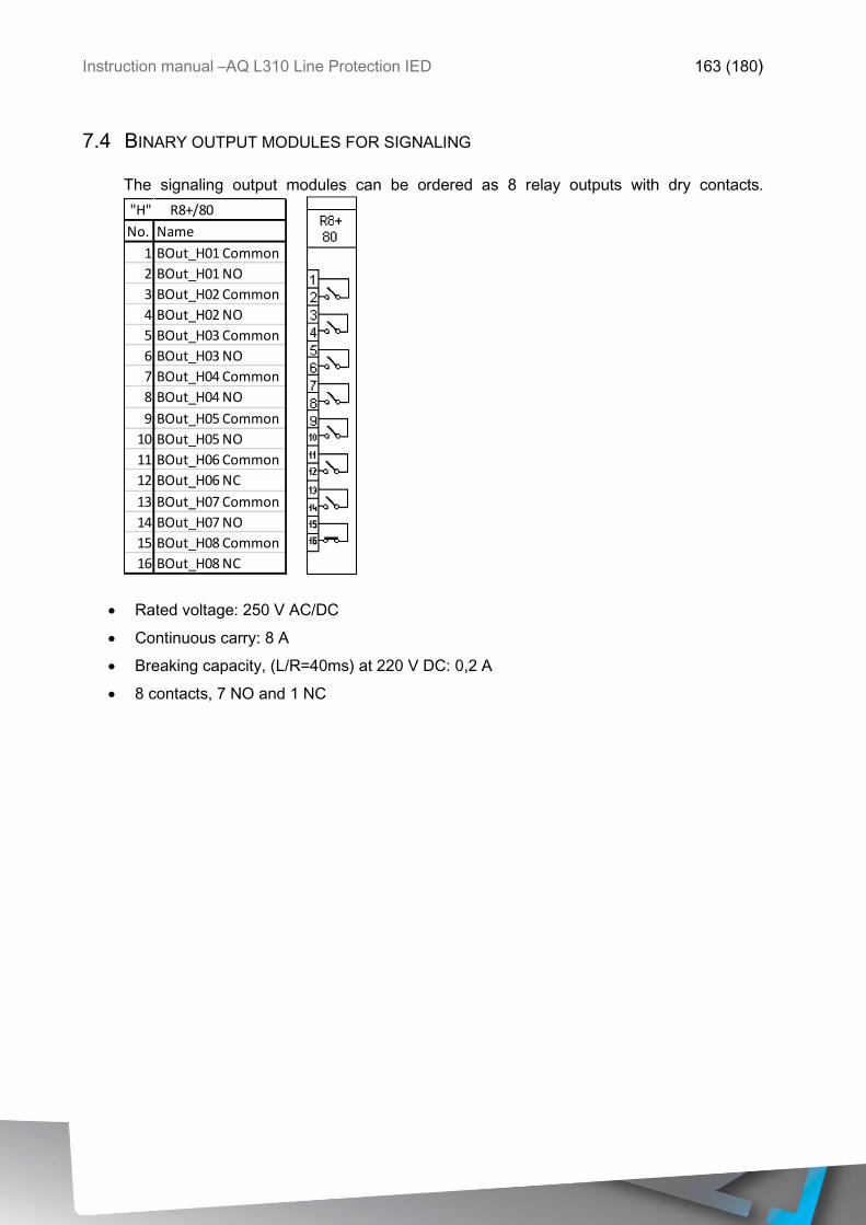
Instruction manual –AQ L310 Line Protection IED 163 (180)
7.4 BINARY OUTPUT MODULES FOR SIGNALING
The signaling output modules can be ordered as 8 relay outputs with dry contacts.
Rated voltage: 250 V AC/DC
Continuous carry: 8 A
Breaking capacity, (L/R=40ms) at 220 V DC: 0,2 A
8 contacts, 7 NO and 1 NC
No. Name
1 BOut_H01 Common
2 BOut_H01 NO
3 BOut_H02 Common
4 BOut_H02 NO
5 BOut_H03 Common
6 BOut_H03 NO
7 BOut_H04 Common
8 BOut_H04 NO
9 BOut_H05 Common
10 BOut_H05 NO
11 BOut_H06 Common
12 BOut_H06 NC
13 BOut_H07 Common
14 BOut_H07 NO
15 BOut_H08 Common
16 BOut_H08 NC
"H" R8+/80
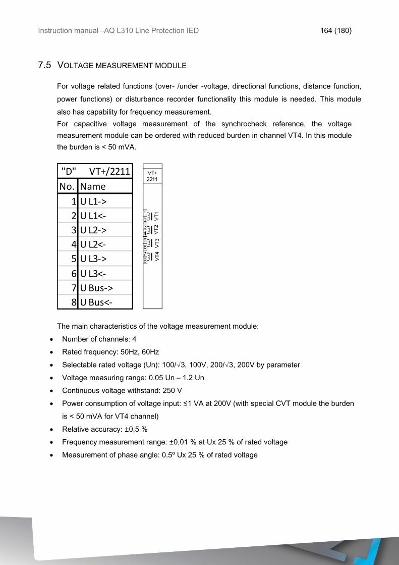
Instruction manual –AQ L310 Line Protection IED 164 (180)
7.5 VOLTAGE MEASUREMENT MODULE
For voltage related functions (over- /under -voltage, directional functions, distance function,
power functions) or disturbance recorder functionality this module is needed. This module
also has capability for frequency measurement.
For capacitive voltage measurement of the synchrocheck reference, the voltage
measurement module can be ordered with reduced burden in channel VT4. In this module
the burden is < 50 mVA.
The main characteristics of the voltage measurement module:
Number of channels: 4
Rated frequency: 50Hz, 60Hz
Selectable rated voltage (Un): 100/√3, 100V, 200/√3, 200V by parameter
Voltage measuring range: 0.05 Un – 1.2 Un
Continuous voltage withstand: 250 V
Power consumption of voltage input: ≤1 VA at 200V (with special CVT module the burden
is < 50 mVA for VT4 channel)
Relative accuracy: ±0,5 %
Frequency measurement range: ±0,01 % at Ux 25 % of rated voltage
Measurement of phase angle: 0.5º Ux 25 % of rated voltage
No. Name
1 U L1->
2 U L1<-
3 U L2->
4 U L2<-
5 U L3->
6 U L3<-
7 U Bus->
8 U Bus<-
"D" VT+/2211
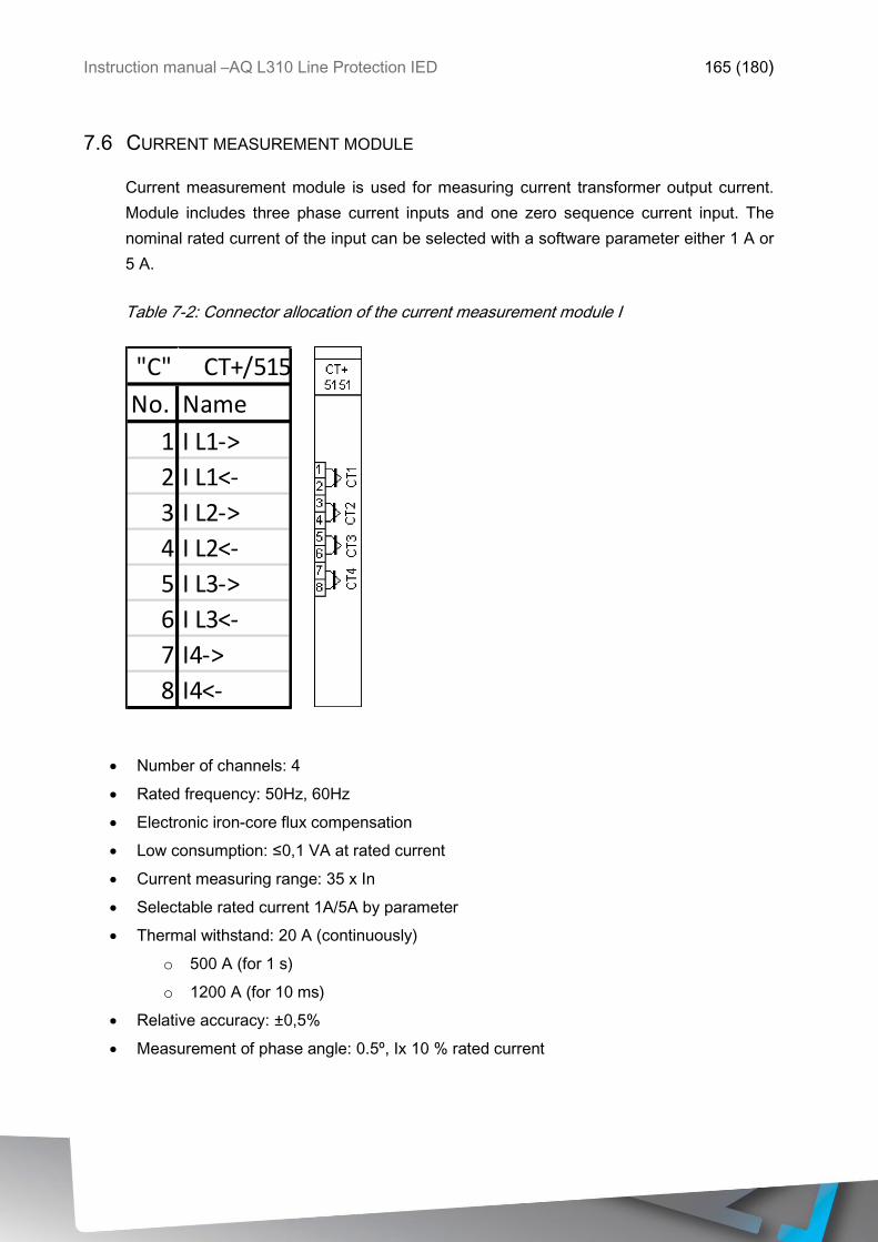
Instruction manual –AQ L310 Line Protection IED 165 (180)
7.6 CURRENT MEASUREMENT MODULE
Current measurement module is used for measuring current transformer output current.
Module includes three phase current inputs and one zero sequence current input. The
nominal rated current of the input can be selected with a software parameter either 1 A or
5 A.
Table 7-2: Connector allocation of the current measurement module I
Number of channels: 4
Rated frequency: 50Hz, 60Hz
Electronic iron-core flux compensation
Low consumption: ≤0,1 VA at rated current
Current measuring range: 35 x In
Selectable rated current 1A/5A by parameter
Thermal withstand: 20 A (continuously)
o 500 A (for 1 s)
o 1200 A (for 10 ms)
Relative accuracy: ±0,5%
Measurement of phase angle: 0.5º, Ix 10 % rated current
No. Name
1 I L1->
2 I L1<-
3 I L2->
4 I L2<-
5 I L3->
6 I L3<-
7 I4->
8 I4<-
"C" CT+/5151
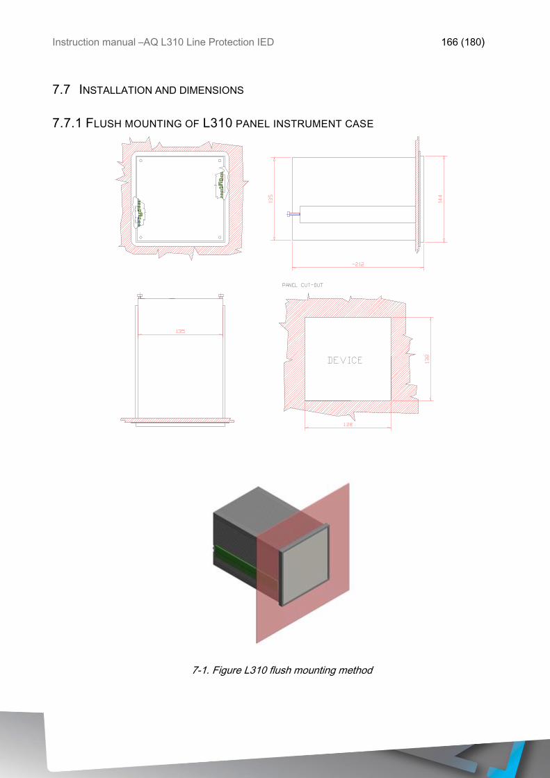
Instruction manual –AQ L310 Line Protection IED 166 (180)
7.7 INSTALLATION AND DIMENSIONS
7.7.1 FLUSH MOUNTING OF L310 PANEL INSTRUMENT CASE
7-1. Figure L310 flush mounting method
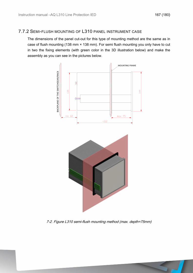
Instruction manual –AQ L310 Line Protection IED 167 (180)
7.7.2 SEMI-FLUSH MOUNTING OF L310 PANEL INSTRUMENT CASE
The dimensions of the panel cut-out for this type of mounting method are the same as in
case of flush mounting (138 mm × 138 mm). For semi flush mounting you only have to cut
in two the fixing elements (with green color in the 3D illustration below) and make the
assembly as you can see in the pictures below.
7-2. Figure L310 semi-flush mounting method (max. depth=75mm)
MOUNTING FRAME
BA
CK
PLA
NE
OF
THE
SWIT
CH
GEA
R/R
AC
K
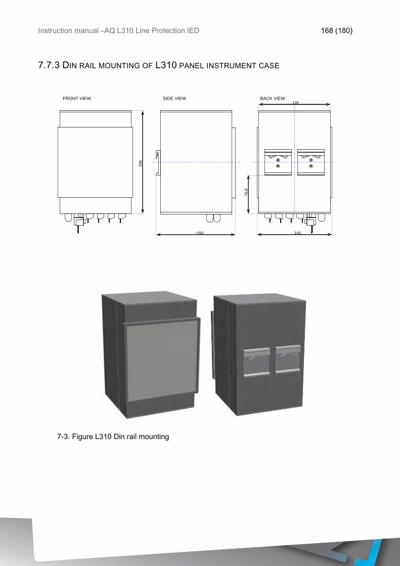
Instruction manual –AQ L310 Line Protection IED 168 (180)
7.7.3 DIN RAIL MOUNTING OF L310 PANEL INSTRUMENT CASE
7-3. Figure L310 Din rail mounting
FRONT VIEW SIDE VIEW
20
6
~150
76
,8
141
135 BACK VIEW
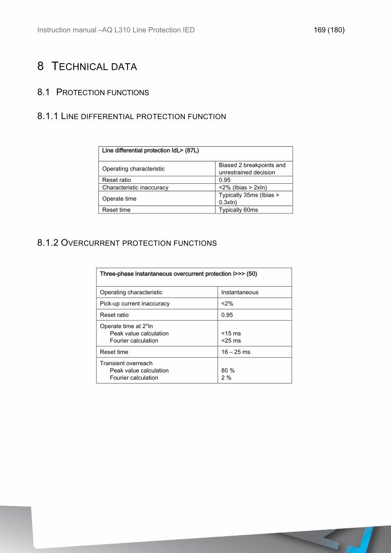
Instruction manual –AQ L310 Line Protection IED 169 (180)
8 TECHNICAL DATA
8.1 PROTECTION FUNCTIONS
8.1.1 LINE DIFFERENTIAL PROTECTION FUNCTION
Line differential protection IdL> (87L)
Operating characteristic Biased 2 breakpoints and
unrestrained decision
Reset ratio 0.95
Characteristic inaccuracy <2% (Ibias > 2xIn)
Operate time Typically 35ms (Ibias >
0.3xIn)
Reset time Typically 60ms
8.1.2 OVERCURRENT PROTECTION FUNCTIONS
Three-phase instantaneous overcurrent protection I>>> (50)
Operating characteristic Instantaneous
Pick-up current inaccuracy <2%
Reset ratio 0.95
Operate time at 2*In
Peak value calculation
Fourier calculation
<15 ms
<25 ms
Reset time 16 – 25 ms
Transient overreach
Peak value calculation
Fourier calculation
80 %
2 %
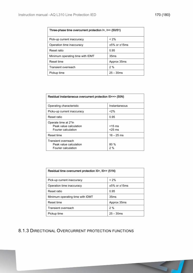
Instruction manual –AQ L310 Line Protection IED 170 (180)
Three-phase time overcurrent protection I>, I>> (50/51)
Pick-up current inaccuracy < 2%
Operation time inaccuracy ±5% or ±15ms
Reset ratio 0.95
Minimum operating time with IDMT 35ms
Reset time Approx 35ms
Transient overreach 2 %
Pickup time 25 – 30ms
Residual instantaneous overcurrent protection I0>>> (50N)
Operating characteristic Instantaneous
Picku-up current inaccuracy <2%
Reset ratio 0.95
Operate time at 2*In
Peak value calculation
Fourier calculation
<15 ms
<25 ms
Reset time 16 – 25 ms
Transient overreach
Peak value calculation
Fourier calculation
80 %
2 %
Residual time overcurrent protection I0>, I0>> (51N)
Pick-up current inaccuracy < 2%
Operation time inaccuracy ±5% or ±15ms
Reset ratio 0.95
Minimum operating time with IDMT 35ms
Reset time Approx 35ms
Transient overreach 2 %
Pickup time 25 – 30ms
8.1.3 DIRECTIONAL OVERCURRENT PROTECTION FUNCTIONS
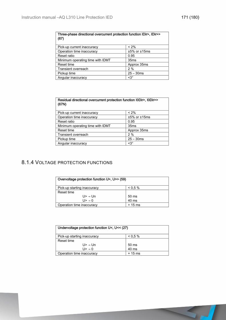
Instruction manual –AQ L310 Line Protection IED 171 (180)
Three-phase directional overcurrent protection function IDir>, IDir>>
(67)
Pick-up current inaccuracy < 2%
Operation time inaccuracy ±5% or ±15ms
Reset ratio 0.95
Minimum operating time with IDMT 35ms
Reset time Approx 35ms
Transient overreach 2 %
Pickup time 25 – 30ms
Angular inaccuracy <3°
Residual directional overcurrent protection function I0Dir>, I0Dir>>
(67N)
Pick-up current inaccuracy < 2%
Operation time inaccuracy ±5% or ±15ms
Reset ratio 0.95
Minimum operating time with IDMT 35ms
Reset time Approx 35ms
Transient overreach 2 %
Pickup time 25 – 30ms
Angular inaccuracy <3°
8.1.4 VOLTAGE PROTECTION FUNCTIONS
Overvoltage protection function U>, U>> (59)
Pick-up starting inaccuracy < 0,5 %
Reset time
U> → Un
U> → 0
50 ms
40 ms
Operation time inaccuracy + 15 ms
Undervoltage protection function U<, U<< (27)
Pick-up starting inaccuracy < 0,5 %
Reset time
U> → Un
U> → 0
50 ms
40 ms
Operation time inaccuracy + 15 ms
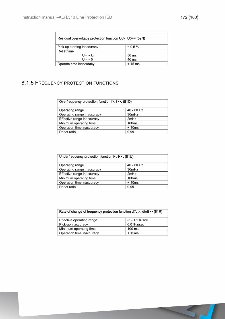
Instruction manual –AQ L310 Line Protection IED 172 (180)
Residual overvoltage protection function U0>, U0>> (59N)
Pick-up starting inaccuracy < 0,5 %
Reset time
U> → Un
U> → 0
50 ms
40 ms
Operate time inaccuracy + 15 ms
8.1.5 FREQUENCY PROTECTION FUNCTIONS
Overfrequency protection function f>, f>>, (81O)
Operating range 40 - 60 Hz
Operating range inaccuracy 30mHz
Effective range inaccuracy 2mHz
Minimum operating time 100ms
Operation time inaccuracy + 10ms
Reset ratio 0,99
Underfrequency protection function f<, f<<, (81U)
Operating range 40 - 60 Hz
Operating range inaccuracy 30mHz
Effective range inaccuracy 2mHz
Minimum operating time 100ms
Operation time inaccuracy + 10ms
Reset ratio 0,99
Rate of change of frequency protection function df/dt>, df/dt>> (81R)
Effective operating range -5 - +5Hz/sec
Pick-up inaccuracy 0,01Hz/sec
Minimum operating time 100 ms
Operation time inaccuracy + 15ms
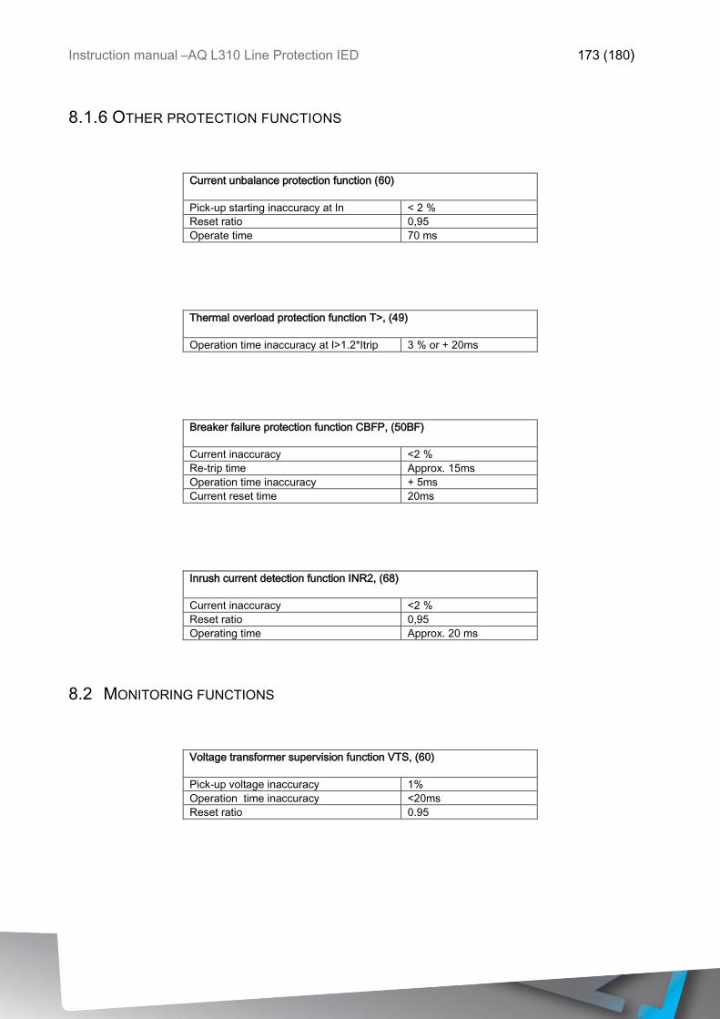
Instruction manual –AQ L310 Line Protection IED 173 (180)
8.1.6 OTHER PROTECTION FUNCTIONS
Current unbalance protection function (60)
Pick-up starting inaccuracy at In < 2 %
Reset ratio 0,95
Operate time 70 ms
Thermal overload protection function T>, (49)
Operation time inaccuracy at I>1.2*Itrip 3 % or + 20ms
Breaker failure protection function CBFP, (50BF)
Current inaccuracy <2 %
Re-trip time Approx. 15ms
Operation time inaccuracy + 5ms
Current reset time 20ms
Inrush current detection function INR2, (68)
Current inaccuracy <2 %
Reset ratio 0,95
Operating time Approx. 20 ms
8.2 MONITORING FUNCTIONS
Voltage transformer supervision function VTS, (60)
Pick-up voltage inaccuracy 1%
Operation time inaccuracy <20ms
Reset ratio 0.95
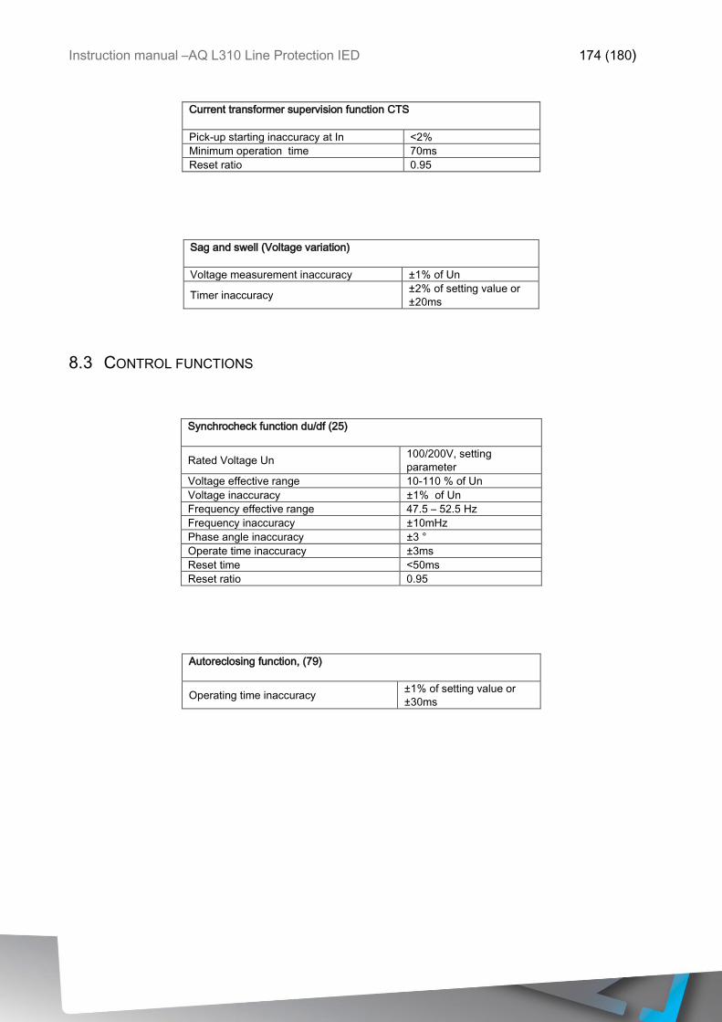
Instruction manual –AQ L310 Line Protection IED 174 (180)
Current transformer supervision function CTS
Pick-up starting inaccuracy at In <2%
Minimum operation time 70ms
Reset ratio 0.95
Sag and swell (Voltage variation)
Voltage measurement inaccuracy ±1% of Un
Timer inaccuracy ±2% of setting value or
±20ms
8.3 CONTROL FUNCTIONS
Synchrocheck function du/df (25)
Rated Voltage Un 100/200V, setting
parameter
Voltage effective range 10-110 % of Un
Voltage inaccuracy ±1% of Un
Frequency effective range 47.5 – 52.5 Hz
Frequency inaccuracy ±10mHz
Phase angle inaccuracy ±3 °
Operate time inaccuracy ±3ms
Reset time <50ms
Reset ratio 0.95
Autoreclosing function, (79)
Operating time inaccuracy ±1% of setting value or
±30ms
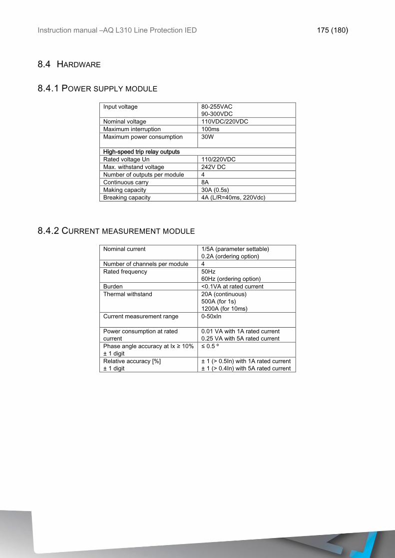
Instruction manual –AQ L310 Line Protection IED 175 (180)
8.4 HARDWARE
8.4.1 POWER SUPPLY MODULE
Input voltage 80-255VAC
90-300VDC
Nominal voltage 110VDC/220VDC
Maximum interruption 100ms
Maximum power consumption
30W
High-speed trip relay outputs
Rated voltage Un 110/220VDC
Max. withstand voltage 242V DC
Number of outputs per module 4
Continuous carry 8A
Making capacity 30A (0.5s)
Breaking capacity 4A (L/R=40ms, 220Vdc)
8.4.2 CURRENT MEASUREMENT MODULE
Nominal current 1/5A (parameter settable)
0.2A (ordering option)
Number of channels per module 4
Rated frequency 50Hz
60Hz (ordering option)
Burden <0.1VA at rated current
Thermal withstand 20A (continuous)
500A (for 1s)
1200A (for 10ms)
Current measurement range 0-50xIn
Power consumption at rated
current
0.01 VA with 1A rated current
0.25 VA with 5A rated current
Phase angle accuracy at Ix ≥ 10%
± 1 digit
≤ 0.5 º
Relative accuracy [%]
± 1 digit
± 1 (> 0.5In) with 1A rated current
± 1 (> 0.4In) with 5A rated current
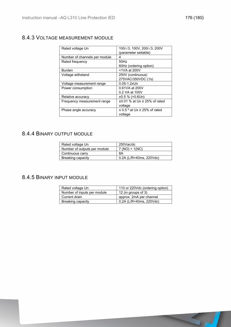
Instruction manual –AQ L310 Line Protection IED 176 (180)
8.4.3 VOLTAGE MEASUREMENT MODULE
Rated voltage Un 100/√3, 100V, 200/√3, 200V
(parameter settable)
Number of channels per module 4
Rated frequency 50Hz
60Hz (ordering option)
Burden <1VA at 200V
Voltage withstand 250V (continuous)
275VAC/350VDC (1s)
Voltage measurement range 0.05-1.2xUn
Power consumption 0.61VA at 200V
0.2 VA at 100V
Relative accuracy ±0.5 % (>0.6Un)
Frequency measurement range ±0.01 % at Ux ≥ 25% of rated
voltage
Phase angle accuracy ≤ 0.5 º at Ux ≥ 25% of rated
voltage
8.4.4 BINARY OUTPUT MODULE
Rated voltage Un 250Vac/dc
Number of outputs per module 7 (NO) + 1(NC)
Continuous carry 8A
Breaking capacity 0.2A (L/R=40ms, 220Vdc)
8.4.5 BINARY INPUT MODULE
Rated voltage Un 110 or 220Vdc (ordering option)
Number of inputs per module 12 (in groups of 3)
Current drain approx. 2mA per channel
Breaking capacity 0.2A (L/R=40ms, 220Vdc)
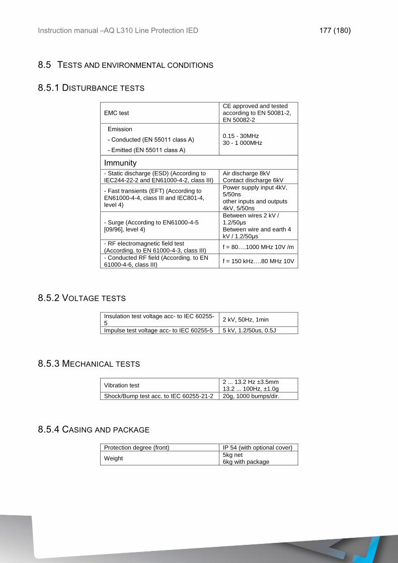
Instruction manual –AQ L310 Line Protection IED 177 (180)
8.5 TESTS AND ENVIRONMENTAL CONDITIONS
8.5.1 DISTURBANCE TESTS
EMC test CE approved and tested according to EN 50081-2, EN 50082-2
Emission
- Conducted (EN 55011 class A)
- Emitted (EN 55011 class A)
0.15 - 30MHz 30 - 1 000MHz
Immunity
- Static discharge (ESD) (According to IEC244-22-2 and EN61000-4-2, class III)
Air discharge 8kV Contact discharge 6kV
- Fast transients (EFT) (According to EN61000-4-4, class III and IEC801-4, level 4)
Power supply input 4kV, 5/50ns other inputs and outputs 4kV, 5/50ns
- Surge (According to EN61000-4-5 [09/96], level 4)
Between wires 2 kV / 1.2/50μs Between wire and earth 4 kV / 1.2/50μs
- RF electromagnetic field test (According. to EN 61000-4-3, class III)
f = 80….1000 MHz 10V /m
- Conducted RF field (According. to EN 61000-4-6, class III)
f = 150 kHz….80 MHz 10V
8.5.2 VOLTAGE TESTS
Insulation test voltage acc- to IEC 60255-5
2 kV, 50Hz, 1min
Impulse test voltage acc- to IEC 60255-5 5 kV, 1.2/50us, 0.5J
8.5.3 MECHANICAL TESTS
Vibration test 2 ... 13.2 Hz ±3.5mm 13.2 ... 100Hz, ±1.0g
Shock/Bump test acc. to IEC 60255-21-2 20g, 1000 bumps/dir.
8.5.4 CASING AND PACKAGE
Protection degree (front) IP 54 (with optional cover)
Weight 5kg net 6kg with package

Instruction manual –AQ L310 Line Protection IED 178 (180)
8.5.5 ENVIRONMENTAL CONDITIONS
Specified ambient service temp. range -10…+55°C
Transport and storage temp. range -40…+70°C
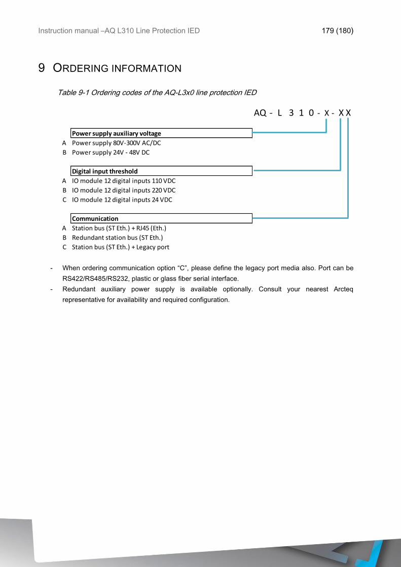
Instruction manual –AQ L310 Line Protection IED 179 (180)
9 ORDERING INFORMATION
Table 9-1 Ordering codes of the AQ-L3x0 line protection IED
- When ordering communication option “C”, please define the legacy port media also. Port can be
RS422/RS485/RS232, plastic or glass fiber serial interface.
- Redundant auxiliary power supply is available optionally. Consult your nearest Arcteq
representative for availability and required configuration.
AQ - L 3 1 0 - X - X X
Power supply auxiliary voltage
A Power supply 80V-300V AC/DC
B Power supply 24V - 48V DC
Digital input threshold
A IO module 12 digital inputs 110 VDC
B IO module 12 digital inputs 220 VDC
C IO module 12 digital inputs 24 VDC
Communication
A Station bus (ST Eth.) + RJ45 (Eth.)
B Redundant station bus (ST Eth.)
C Station bus (ST Eth.) + Legacy port

Instruction manual –AQ L310 Line Protection IED 180 (180)
10 REFERENCE INFORMATION
Manufacturer information:
Arcteq Ltd. Finland
Visiting and postal address:
Wolffintie 36 F 11
65200 Vaasa, Finland
Contacts:
Phone, general and commercial issues (office hours GMT +2): +358 10 3221 370
Fax: +358 10 3221 389
url: www.arcteq.fi
email sales: [email protected]
email technical support: [email protected]